a theoretical study on the heat transfer process in diesel ... · a theoretical study on the heat...
TRANSCRIPT
A theoretical study on the heat transfer processin diesel engines
H. Fridriksson1, B. Sunden1 & S. Hajireza2
1 Department of Energy Sciences, Lund University, Sweden2 Thermal and Combustion Technology, Sweden
Abstract
The current and future emissions regulations and demands on internal combustionengines have increased the need for improvement of the thermal design and engineefficiency. This paper reports an initial investigation concerning in-cylinder heattransfer. In addition, a literature review in this field is presented. It was foundthat no extensive application studies have been performed on full cylinder heattransfer by taking the effect of combustion and gas exchange into the account.The available literature is mainly focused on individual component studies andsub-model improvements.
Furthermore, a simple parameter study is performed in order to estimate thecontribution of each parameter on the in-cylinder engine heat transfer. This is doneby setting up an engine segment, using the commercial CFD tool AVL FIRE andthe automatic mesh generator AVL Ese Diesel. Engine segment simulations aremade for the period between IVC (intake valve closing) and EVO (exhaust valveopening). The parameter study revealed that most of the parameters selected doin-fact significantly affect the in-cylinder heat transfer. However, the effects on theindicated mean effective pressure, or indicated power output, are different.Keywords: engine heat transfer, CFD, AVL FIRE, Parameter study.
1 Introduction
With todays strict requirements on internal combustion (IC) engine performance,with regards to emissions, it becomes more important to obtain optimized enginedesign, using computational fluid dynamics (CFDs) tools. The latest developmentsin IC engine design are leading towards smaller, more compact and efficientengines, which prove to be quite demanding on the combustion control and engine
www.witpress.com, ISSN 1743-3533 (on-line) WIT Transactions on Engineering Sciences, Vol 68, © 2010 WIT Press
Advanced Computational Methods and Experiments in Heat Transfer XI 177
doi:10.2495/HT100161
cooling. The major limitation to achieving higher efficiency of the modern ICengine is its thermodynamic cycle, i.e., the conversion of chemically released heat,through combustion, to mechanical work. With modern combustion schemes, theheat flux to the walls is highly transient, where the heat flux to a single wallcan vary from zero to as much as 10 MW/m2 and back to zero again within 10ms. Additionally, two locations on the wall separated by only 1 cm can receivepeaks in heat flux differing in magnitude of up to 5 MW/m2. These loads arealso subject to considerable cycle-to-cycle variations [1, 2]. Predicting the spatialthermal distribution inside the engine cylinder during one engine cycle has provento be a difficult task. Therefore, researchers often focus on one specific enginecomponent, using somewhat simplified boundary conditions.
The combustion process of the diesel engine is a relatively well documentedprocess, as described in [3–5], among others. Since the early days of combustionengine development, various experimental data have been used to foster the knowl-edge on the different phenomena occurring in the engine. This is, however, notalways a feasible option, since the piston engine is not easily accessible for exper-imental measurements, and the probes and other apparatus used for experimentsinterfere with the natural flow field in the engine. Furthermore, in some experimen-tal applications the material strength of the engine cylinder components has to becompromised for better visualization, e.g., quartz glass windows for optical mea-surements. This underlines the value of computational “experiments”, e.g., in theform of CFD simulations for the combustion engine development. As CFD is a rel-atively new field within combustion engines, it is constantly being developed as thecomputational power is increased. The predecessor to modern computational sim-ulations in engine heat transfer applications are the one dimensional steady stateevaluations of the heat transfer coefficient. Borman and Nishiwaki [1] describethe transition of these heat transfer coefficient correlations from the empiricalcorrelation presented by Nusselt in 1923 [6] and the more widely used empiricalcorrelations presented by Eichelberg in 1939, towards the most commonly knowncorrelations, based on the similarity law of steady turbulent heat transfer. The mostwidely known correlations of this form are the ones presented by Annand andMa [7] and Woschni [8]. The historical use of the Woschni equation is exemplifiedby experimental situations, such as [9], and modified versions of the equation havebeen used in so-called “one-zone” models, as described by [10]. Today a rangeof one-dimensional simulation codes, often referred to as gas-exchange codes,make use of a modified version of the Woschni equation in the heat transferassessment. Attempts have been made to contribute with new correlations for theheat transfer coefficient for 1-D codes, both for specific types of engines [11–13]and for specific parts of the engine [14]. Sanli et al. [15], presented a summary ofthe available correlations for SI-engines, as well as an evaluation of these, showingthat they do in fact differ quite a bit in their predictions of heat flux and heat transfercoefficients.
In three-dimensional studies these gas-exchange codes are frequently used inorder to provide starting values and/or boundary conditions for the simulations.This is especially true for the calculation of the temperature distribution in solid
www.witpress.com, ISSN 1743-3533 (on-line) WIT Transactions on Engineering Sciences, Vol 68, © 2010 WIT Press
178 Advanced Computational Methods and Experiments in Heat Transfer XI

components of the engine, where the heat transfer coefficient is one of theboundary conditions, such as in [2]. Other studies, such as [16], use the one-dimensional codes in order to obtain wall temperatures as boundary conditions,in order to simplify the computational domain. Along with more computationalpower, more and more researchers have included both the bulk gas and the solidregions in the computational domain, which means that the wall temperatures areresolved in the CFD simulation [17–23].
The development of CFD models for diesel engine application is an ongoingprocess. Reitz and Rutland [24] list a few of the models needed in order tosuccessfully simulate a diesel engine cycle, as well as their development until1995. Since then, there have been vast improvements, such as the formulationof temperature wall functions [25] and near wall treatment for turbulence incombination with conjugate heat transfer [26], to name a few.
In the work presented here, the effects of heat transfer from the variation ofdifferent geometrical and operational parameters are studied by using the CFDtools AVL FIRE and AVL ESE Diesel.
2 Problem statement
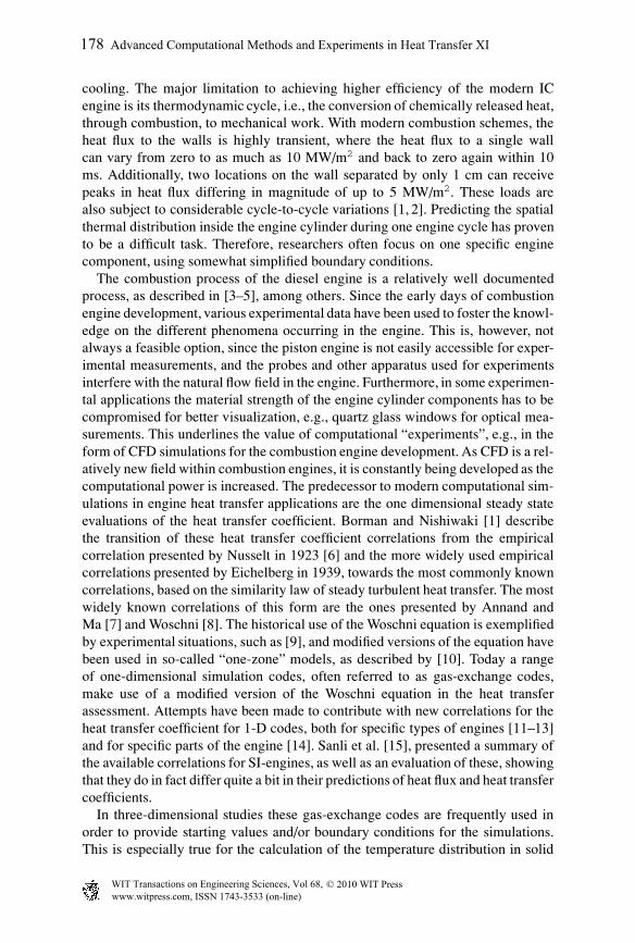
In order to determine the in-cylinder heat transfer for the different simulationcases presented in the next section, a segment of an engine cylinder was createdusing AVL ESE Diesel, and this is used throughout the simulation process. Theengine geometrical parameters used in this work are specified in Table 1. Themain computational grid consists of an average cell size ranging from 0.75 to 1.00mm. At the wall boundaries there are two layers, 0.20 mm in thickness, whichare supposed to capture the phenomena occurring in the thermal boundary layer.The simulated segment only encloses a fuel spray from one orifice of the injectionnozzle and the assumption of a cyclic symmetry is made. The number of angularsubdivisions in this segment is 17, i.e., there are 17 computational cells in theangular direction. These specifications lead to grid densities of 35.000 and 62.000computational cells at TDC and BDC, respectively. The computational mesh ofthe combustion bowl at TDC is shown in Figure 1.
The governing equations for unsteady, compressible turbulent flow along withthe energy equation and species transport were solved from IVC to EVO, by the
Table 1: Engine specifications.
Bore [mm] 105
Stroke [mm] 120
Conn.rod length [mm] 200
Piston pin offset [mm] 0
Compression ratio 16:1
No. of nozzle orifices 7
www.witpress.com, ISSN 1743-3533 (on-line) WIT Transactions on Engineering Sciences, Vol 68, © 2010 WIT Press
Advanced Computational Methods and Experiments in Heat Transfer XI 179
Figure 1: Mesh of the combustion bowl at TDC.
commercial CFD code AVL FIRE [27]. The turbulent flow field is modeled withthe k-zeta-f model, using hybrid wall treatment and standard wall functions forthe wall heat transfer. The combustion model used is the so-called ECFM-3Zversion of the coherent flame model. Other physical phenomena accounted forin the simulation are evaporation and breakup, described by the Dukowitz andWave models, respectively, while soot and NO formation are predicted by the LundFlamelet model and the extended Zeldovich mechanism, respectively. All modelsused are described and referenced in the AVL FIRE v2009 user manual [27]. Allinitial and boundary conditions used in this work, and presented in the next section,were provided by a 1D gas exchange code simulation.
3 Boundary conditions
The duration time of the simulation is kept constant for all cases, i.e., the valvetimings are not changed. The inlet valve is closed at 160 CAD before TDC(BTDC), while the exhaust valve opens at 130 CAD after TCD (ATDC). Theengine cylinder was initialized every simulation run with the pressure of 4.35 bar,temperature of 411 K and the swirl number of 1.5. The fuel used in the simulationswas AVL’s predefined diesel fuel and the EGR level at IVC was set to a massfraction of 28%. Out of these parameters, the swirl number and EGR level will bechanged in the parameter sweep, presented in Table 2.
The total amount of fuel used in the whole cylinder is 98.32 mg, which meansthat the amount of fuel in the engine segment of the baseline case is roughly 14mg (one seventh). The nozzle hole diameter, which is 0.169 mm, determines thesize of the biggest droplets inside the computational domain. The injection of fuelis started at the top most position of the piston (TDC) and as seen in Table 2 itsduration varies from 30 to 34 CAD. The table even shows the variation in thespray angle, which varies from 140 to 160◦, and engine speed, which varies from2000 to 3000 RPM. Other parameters altered during the simulations are EGR level,
www.witpress.com, ISSN 1743-3533 (on-line) WIT Transactions on Engineering Sciences, Vol 68, © 2010 WIT Press
180 Advanced Computational Methods and Experiments in Heat Transfer XI

Table 2: Values of the parameter sweep.
Parameter Lower value Baseline Higher value
Engine speed [RPM] 2000 2500 3000
EGR [-] 0.25 0.28 0.35
Injection dur. [CAD] 30 32 34
Swirl [-] 1.4 1.5 1.8
Spray angle [deg] 140 160 180
No. of inj. orifices [-] 6 7 8
swirl level and the number of injector holes, which calls for computational grids ofdifferent sizes since the computational domain only encloses one spray. The totalnumber of simulation runs performed was therefore 1 + 12 = 13 runs.
As for the thermal boundary conditions at the wall regions, all walls have beenassigned constant temperatures. The piston wall and the cylinder head have bothbeen assigned a temperature of 550K and the cylinder liner has been assigned atemperature of 460K.
4 Results
In this section the result from the simulations will be presented in the form of heatflux to boundary walls and the corresponding heat transfer coefficients (HTC).In order to estimate the effect on the indicated engine output for each simulationrun, the mean pressure trace will be used to evaluate the indicated mean effectivepressure of the combustion stroke (IMEP co). This value is not to be confusedwith the conventional engine IMEP, which is normally an estimation of the wholecycle, including the gas exchange part. Furthermore, to observe if the combustionitself will be affected in the simulation run, the rate of heat release (RoHR) isexamined as a function of crank angle degree.
4.1 Baseline case
The heat flux values of the baseline case can be found in the first row of Table 3as well as the solid lines of all the plots in Figure 2, where the rate of heat release,with the units [J/CAD] is plotted as a function of crank angle degree. The rate ofheat release curve presented here is typical for a diesel combustion, where thereis a short peak in heat release shortly after injection (∼5 CAD), followed by abroader, longer peak. The shorter peak is representative for the premixed part ofthe combustion, while the larger, more dominant part, is representative for thediffusion flame. It is worth mentioning that the heat release curves presented hereare scaled up to the full cylinder, i.e., the result for a 1/7 segment of the engine have
www.witpress.com, ISSN 1743-3533 (on-line) WIT Transactions on Engineering Sciences, Vol 68, © 2010 WIT Press
Advanced Computational Methods and Experiments in Heat Transfer XI 181

Table 3: Heat transfer and indicated mean pressure results for all cases.
Heat flux [W] HTC [W/m2K] IMEPco
Head Liner Piston Head Liner Piston
Baseline 862 418 1098 1432 1587 1523 15.79
Engine speed [RPM]
2000 707 355 892 1225 1331 1297 15.58
3000 1027 495 1286 1638 1835 1739 15.92
EGR mass fraction [-]
25% 872 431 1095 1434 1586 1521 15.79
35% 856 430 1084 1432 1586 1523 15.71
Swirl number [-]
1.4 872 442 1083 1420 1565 1506 15.74
1.8 842 393 1108 1489 1662 1567 15.77
Spray angle [deg]
140 746 344 1244 1456 1594 1561 16.04
180 562 238 1125 1447 1574 1683 9.24
Injection duration [CAD]
30 922 411 1133 1443 1596 1536 16.04
34 815 438 1052 1429 1577 1508 14.48
Number of injection holes [-]
6 1183 545 1348 1461 1600 1546 15.99
8 666 341 906 1438 1576 1506 15.39
been multiplied by 7 in order to obtain the total rate of heat release for the cylinder.As mentioned above, Table 3 includes values for the IMEP of the combustion,which is around 15.79 bar for the baseline case. The values for the heat flux andthe heat transfer coefficient for each wall, presented in the table, are the integratedvalues for the entire wall surface and therefore have the unit [W]. The results showthat in this case the total heat transfer during the combustion phase is highest atthe piston surface.
4.2 Engine speed
From the heat release curve, at the top left corner of Figure 2, it can be seen thatthe effects of engine speed are most clearly visible in the “premixed” part of thecombustion process, during the first five crank angle degrees. The effects of engine
www.witpress.com, ISSN 1743-3533 (on-line) WIT Transactions on Engineering Sciences, Vol 68, © 2010 WIT Press
182 Advanced Computational Methods and Experiments in Heat Transfer XI

0 10 20 30 40 50 60 70CAD [deg]
0
20
40
60
80
100
120
140R
oHR
[J/d
eg]
2000 RPM2500 RPM (ref)3000 RPM
Rate of Heat Releasefor different engine speeds
0 10 20 30 40 50 60 70CAD [deg]
0
20
40
60
80
100
120
140
RoH
R[J
/deg
]
25% EGR28% EGR (ref)35% EGR
Rate of Heat Releasefor different EGR values
0 10 20 30 40 50 60 70CAD [deg]
0
20
40
60
80
100
120
140
RoH
R[J
/deg
]
Sw nr 1.4Sw nr 1.5Sw nr 1.8
Rate of Heat Releasefor different swirl numbers
0 10 20 30 40 50 60 70CAD [deg]
0
20
40
60
80
100
120
140
RoH
R[J
/deg
]
140 deg160 deg180 deg
Rate of Heat Releasefor different spray angles
0 10 20 30 40 50 60 70CAD [deg]
0
20
40
60
80
100
120
140
RoH
R[J
/deg
]
30 deg32 deg34 deg
Rate of Heat Releasefor different injection durations
0 10 20 30 40 50 60 70CAD [deg]
0
20
40
60
80
100
120
140
RoH
R[J
/deg
]
6 holes7 holes8 holes
Rate of Heat Releasefor different number of injection holes
Figure 2: Rate of heat release for all the simulation runs.
speed, however, seem to be less on the diffusion flame, which occurs later in theexpansion stroke of the engine. When examining the values in Table 3, it can befound that without considerable change in the output effect (IMEPco), the heattransfer characteristic shows a considerable change with variable engine speeds.It is evident that with doubled engine speed, the heat transfer rate to the wallsis roughly doubled. This is somewhat expected, since the gas velocity inside theengine cylinder scales with piston speed and therefore, the heat transfer also scalesalmost linearly with the piston speed.
www.witpress.com, ISSN 1743-3533 (on-line) WIT Transactions on Engineering Sciences, Vol 68, © 2010 WIT Press
Advanced Computational Methods and Experiments in Heat Transfer XI 183

4.3 EGR
The effects of EGR level variation on the rate of heat release are shown at the topright corner of Figure 2. Changing the EGR mass fraction from 0.25 to 0.35 doesnot seem to effect the heat release rate. This might indicate that there is enoughamount of oxidants in the system to completely combust the fuel in the cylinder,even though combustion products are recirculated into the combustion event. Thevalues from the table show that the effects on wall heat transfer are minimal, butthe trend in the effect output show a small decrease in IMEPco with a higher EGRmass fraction. Normally EGR is used in combustion engines in order to lowerthe combustion temperature for the purpose of emission control. This is usuallyfollowed by a penalty in the output effect, shown here by the decreasing trend ofthe IMEPco variable.
4.4 Swirl
The heat transfer results for swirl in Table 3 show no significant change in thewall heat flux for the piston and head surfaces, but a slight decrease (∼ 11%) inliner heat flux was discovered with an elevated swirl number from 1.4 to 1.8. Thevalues for the integrated heat transfer coefficient are a bit more sensitive to thechange in swirl level. The values for the IMEPco show a minimal increase withthe higher swirl number. The effects on the heat release rate, shown in the middleleft part of Figure 2, are almost non-existent. The swirl level normally enhancesthe mixing of fuel and air in the combustion bowl and the almost non-existentchange in effect and heat transfer characteristics indicate that this swirl level doesnot severely effect the fuel-air mixing inside the current combustion bowl shape.
4.5 Spray angle
The effects on the heat release rate from variable spray angle are shown in themiddle left part of Figure 2. The heat release rate seems to be extremely sensitiveto the angle with which the fuel is injected at. Each combustion bowl shape hasits optimal injection angle, for the best possible fuel-air mixing process. For thisparticular bowl shape, the 140◦ injection angle seems to provide the best fuel-air mixing, as well as the highest IMEPco. This, however, comes with the price ofhigher heat fluxes to all wall surfaces. The extremely poor combustion for the 180◦
angle can be explained by the fact that the fuel is injected along the cylinder headand most likely straight into the squish area. This will lead to poor fuel-air mixingand poor combustion, leading to low peak temperatures and low mechanical workoutput.
4.6 Injection duration
Changing the duration time of the fuel injection, keeping the total fuel mass con-stant, clearly effects both the heat release rate and the wall heat transfer, as shown
www.witpress.com, ISSN 1743-3533 (on-line) WIT Transactions on Engineering Sciences, Vol 68, © 2010 WIT Press
184 Advanced Computational Methods and Experiments in Heat Transfer XI

in the bottom left corner of Figure 2 and Table 3. Furthermore, increasing theduration of 4 CAD lowers the IMEPco from ∼16 bar to ∼14.5 bar. It is clear thatwith a shorter injection duration, more fuel is injected at each crank angle degreeand assuming that there is enough oxygen for complete combustion, the shorterinjection duration should increase the heat release rate during the injection. In thiscase it seems to be so.
4.7 Number of injection holes
With the number of injection holes changed from six to eight, seven being thereference case, there seems to be a significant impact on the heat release rate andthe wall heat transfer, without significant changes in the combustion IMEP. Thisis the only case in this 12+1 simulation runs which has required the generationof new meshes for each parameter, i.e., the size of the three engine segmentmeshes here is not the same (1/6, 1/7 and 1/8). This means that the computationalvolume has changed, however, the total amount of fuel injected in the segmentwas adjusted accordingly. Since the volume has changed, the segment includingthe smaller volume might encounter stronger interactions with the adjacent spray,i.e., the cyclic symmetry assumption might be somewhat questionable for a toosmall volume.
5 Discussion
The literature study included in the introduction shows that the knowledge onthe heat transfer processes in the combustion engine is a vital subject for theoptimized operation of the engine. Today there are few investigations that havefocused on the cylinder as a whole when it comes to heat transfer applications,whereas most researchers have chosen, for various reasons, to focus on individualengine components or improvements on individual models. The combination ofthose should, however, be used in an application study in order to quantify theeffect of heat transfer at various load points and configurations.
From the engine segment simulation parameter study, it can be assumed that forthe given combustion bowl the injection properties, i.e., spray angle and injectionduration etc., are critical when it comes to wall heat transfer. This is mostlydue to the fact that these parameters determine the quality of the combustion,and therefore the peak temperature achieved in the combustion phase. Otherparameters that significantly effect wall heat transfer for the given combustionbowl shape showed to be engine speed and number of injection nozzles. It is clearthat for any combustion bowl shape, the heat transfer coefficient and, therefore,wall heat fluxes will scale with the bulk gas velocity, which scales linearly with thepiston speed. However, the observed effects from the number of injection nozzleson the wall heat transfer are somewhat unexpected and need further investigation.
The fact that the EGR mass fraction did not effect the wall heat fluxes more thanobserved, was not really expected. This might, however, be explained by the factthat the load point selected in this case, i.e., amount of fuel used etc., cancels out
www.witpress.com, ISSN 1743-3533 (on-line) WIT Transactions on Engineering Sciences, Vol 68, © 2010 WIT Press
Advanced Computational Methods and Experiments in Heat Transfer XI 185
the expected cooling effects of an elevated EGR mass fraction. In this moderate,as it seems, load point, the fuel is fully consumed even though more EGR is used,indicating sufficient oxygen levels in the mixture at all times.
No significant changes in wall heat transfer were observed for the variation ofswirl levels. The values chosen were obviously not far enough apart to effect thecombustion and heat transfer processes, since the load point was not a full load one.This should in fact be examined with a full load case for more detailed evaluation,since at a full load point the fuel-air mixing should be more sensitive to variationin swirl levels.
6 Conclusions
Further knowledge on the temperature distribution inside an engine cylinder aswell as the heat transfer process is critical in order to produce engines withhigher specific power output, as well as lower emissions. In theory, the theoreticalefficiency of the diesel thermodynamic cycle is proportional to the ratio of thepeak temperature and the ambient inlet temperature in the system. This posesrequirements on the material side which have no solutions, so in order to raisethe efficiency of the engine, a detailed knowledge of the thermodynamic behaviorof the system is required. This work is a first step on the way towards deeperunderstanding of this phenomenon, and the parameter study included in this paperhighlights briefly how some parameters can affect the in-cylinder heat transfer.This study should be extended to include more parameters and evaluation of theindividual models used to obtain the current results.
Acknowledgement
The Swedish Energy Agency financially supports this project.
References
[1] Borman, G. & Nishiwaki, K., Internal-combustion engine heat transfer.Progress in energy and combustion science, 13(1), pp. 1–46, 1987.
[2] Liu, Z., Jiang, Y., Dong, Z., Pi, B. & Liu, Y., 3-D Numerical Simulationof Transient Heat Transfer among Multi-Component Coupling System inInternal Combustion Chamber. SAE International, 2008. 2008-01-1818.
[3] Heywood, J., Internal Combustion Engine Fundamentals. McGraw-Hill:New York, NY, 1988.
[4] Kamimoto, T. & Kobayashi, H., Combustion processes in diesel engines.Progress in Energy and Combustion Science, 17(2), pp. 163–189, 1991.
[5] Johansson, B., Forbranningsmotorer. Lund University: Lund, Sweden, 2006.(in Swedish).
[6] Nusselt, W., Der Warmeubergang in der Verbrennungskraftmaschine. Z VerDt Ing, 67, p. 692, 1923.
www.witpress.com, ISSN 1743-3533 (on-line) WIT Transactions on Engineering Sciences, Vol 68, © 2010 WIT Press
186 Advanced Computational Methods and Experiments in Heat Transfer XI

[7] Annand, W. & Ma, T., Instantaneous heat transfer rates to the cylinder headsurface of a small compression-ignition engine. Proceedings of the Institutionof Mechanical Engineers, 185, pp. 976–987, 1970.
[8] Woschni, G., Universally applicable equation for the instantaneous heattransfer coefficient in the internal combustion engine. SAE International,1967. 670931.
[9] Torregrosa, A., Olmeda, P., Degraeuwe, B. & Reyes, M., A concise walltemperature model for DI diesel engines. Applied Thermal Engineering,26(11-12), pp. 1320–1327, 2006.
[10] Descieux, D. & Feidt, M., One zone thermodynamic model simulationof an ignition compression engine. Applied Thermal Engineering, 27(8-9),pp. 1457–1466, 2007.
[11] Beary, A., Study on Heat Transfer Correlations in IC Engines. SAE Interna-tional, 2008. 2008-01-1816.
[12] Galindo, J., Lujan, J., Serrano, J., Dolz, V. & Guilain, S., Description of aheat transfer model suitable to calculate transient processes of turbochargeddiesel engines with one-dimensional gas-dynamic codes. Applied ThermalEngineering, 26(1), pp. 66–76, 2006.
[13] Soyhan, H., Yasar, H., Walmsley, H., Head, B., Kalghatgi, G. & Sorusbay, C.,Evaluation of heat transfer correlations for HCCI engine modeling. AppliedThermal Engineering, 29(2-3), pp. 541–549, 2009.
[14] Depcik, C. & Assanis, D., A universal heat transfer correlation for intakeand exhaust flows in an spark-ignition internal combustion engine. SAEInternational, 111(3), pp. 734–740, 2002.
[15] Sanli, A., Sayin, C., Gumus, M., Kilicaslan, I. & Canakci, M., NumericalEvaluation by Models of Load and Spark Timing Effects on the In-CylinderHeat Transfer of a SI Engine. Numerical Heat Transfer, Part A: Applications,56(5), pp. 444–458, 2009.
[16] Hajireza, S., Regner, G., Christie, A., Egert, M. & Mittermaier, H., Applica-tion of CFD Modeling in Combustion Bowl Assessment of Diesel Enginesusing DoE Methodology. SAE International, 2006. 2006-01-3330.
[17] Liu, Y. & Reitz, R., Modeling of heat conduction within chamber wallsfor multidimensional internal combustion engine simulations. InternationalJournal of Heat and Mass Transfer, 41(6-7), pp. 859–869, 1998.
[18] Kojima, T. & Nishiwaki, K., Numerical analysis of heat transfer in heatinsulated diesel engines. JSAE Review, 15(2), pp. 133–140, 1994.
[19] Kajiwara, H., Fujioka, Y., Suzuki, T. & Negishi, H., An Analytical Approachfor Prediction of Piston Temperature Distribution in Diesel Engines. Pro-ceedings JSAE Annual Congress, pp. 9–12, 2002.
[20] Urip, E., Liew, K., Yang, S. & Arici, O., Numerical Investigation of HeatConduction with Unsteady Thermal Boundary Conditions for Internal Com-bustion Engine Application. Proceedings of IMECE04 2004 ASME Inter-national Mechanical Engineering Congress and Exposition, IMECE2004-59860, 2004.
www.witpress.com, ISSN 1743-3533 (on-line) WIT Transactions on Engineering Sciences, Vol 68, © 2010 WIT Press
Advanced Computational Methods and Experiments in Heat Transfer XI 187

[21] Urip, E., Liew, K. & Yang, S., Modeling IC Engine Conjugate Heat TransferUsing the KIVA Code. Numerical Heat Transfer Part A: Applications, 52(1),pp. 1–23, 2007.
[22] Noori, A. & Rashidi, M., Computational Fluid Dynamics Study of HeatTransfer in a Spark-Ignition Engine Combustion Chamber. Journal of HeatTransfer, 129, p. 609, 2007.
[23] Mohammadi, A., Yaghoubi, M. & Rashidi, M., Analysis of local convectiveheat transfer in a spark ignition engine. International Communications inHeat and Mass Transfer, 35(2), pp. 215–224, 2008.
[24] Reitz, R. & Rutland, C., Development and Testing of Diesel Engine CFDModels. Progress Energy Combustion Science, 21, pp. 173–196, 1995.
[25] Han, Z. & Reitz, R., A temperature wall function formulation for variable-density turbulent flows with application to engine convective heat transfermodeling. International Journal of Heat and Mass Transfer, 40(3), pp. 613–625, 1997.
[26] Nuutinen, M., Kaario, O. & Larmi, M., Conjugate Heat Transfer in CI EngineCFD Simulations. SAE International, 2008. 2008-01-0973.
[27] Avl fire v2009 user manual., 2009.
www.witpress.com, ISSN 1743-3533 (on-line) WIT Transactions on Engineering Sciences, Vol 68, © 2010 WIT Press
188 Advanced Computational Methods and Experiments in Heat Transfer XI