heat transfer enhancement of spray cooling with ammonia by microcavity surfaces
TRANSCRIPT

at SciVerse ScienceDirect
Applied Thermal Engineering 50 (2013) 245e250
Contents lists available
Applied Thermal Engineering
journal homepage: www.elsevier .com/locate/apthermeng
Heat transfer enhancement of spray cooling with ammoniaby microcavity surfaces
B.H. Yang a,b, H. Wang a,b,*, X. Zhu a,b, Q. Liao a,b, Y.D. Ding a,b, R. Chen a,b
aKey Laboratory of Low-grade Energy Utilization Technologies and Systems, Ministry of Education, Chongqing University, Shazheng Street Shapingba District,Chongqing 400030, Chinab Institute of Engineering Thermophysics, Chongqing University, Chongqing 400030, China
h i g h l i g h t s
< Heat sinks with microcavity surface were structured for spray cooling.< Microcavity surfaces gained higher heat transfer coefficient.< Microcavity surfaces ensured low surface temperature with uniform distribution.< Low Bo number is preferred to enhancement of spray cooling performance.
a r t i c l e i n f o
Article history:Received 6 April 2012Accepted 12 June 2012Available online 20 June 2012
Keywords:Spray coolingMicrocavity surfacesAmmoniaSurface temperature
* Corresponding author. Key Laboratory of Low-grnologies and Systems, Ministry of Education, ChonStreet Shapingba District, Chongqing 400030, China.
E-mail address: [email protected] (H. Wang
1359-4311/$ e see front matter � 2012 Elsevier Ltd.http://dx.doi.org/10.1016/j.applthermaleng.2012.06.02
a b s t r a c t
In the present work, spray cooling heat transfer performances with ammonia as coolant were experi-mentally investigated on three self-manufactured microcavity surfaces and the enhancement of heattransfer over that of flat surface was also examined. The experimental results showed that almost thesame heat transfer performance was obtained at low surface superheats for different heat transfersurfaces due to the fact that the single phase convection dominated the heat transfer process. Themicrocavity surfaces exhibited uniform temperature distribution and higher heat transfer coefficientthan that on the flat surface at high surface superheats once the heat transfer was dominated by thenucleate boiling. This was because that the capillary effect induced by the microcavity structure results indramatic reduction in heat transfer resistance and then enhancement of the nucleate boiling. It was alsofound that the microcavity surface with the lowest Bo number of 0.1004 yielded the maximum heattransfer coefficient of 148,245 W/m2$K at the heat flux of 451 W/cm2 as a result of the strongest capillaryeffect. In the meantime, low surface temperature of below 0 �C and uniform temperature distributionwith deviation below �1.5 �C at the heat flux of 420 W/cm2 was simultaneously achieved.
� 2012 Elsevier Ltd. All rights reserved.
1. Introduction
The devices, such as Insulated Gate Bipolar Transistor (IGBT)modules, high power lasers, advanced metallurgical processes andelectronics components, have been getting more powerful andcompact, resulting in urgent need for enhancing heat dissipation. Asexpected, the highheat-fluxcooling techniques, that notonlyenablea large amount of heat dissipation but also maintain a low surfacetemperature, have received ever-increasing attention in recentyears. Several newly efficient cooling techniques have been
ade Energy Utilization Tech-gqing University, Shazheng
).
All rights reserved.9
proposed, includingmicro channel cooling and jet impingement etc.However, one of the critical drawbacks in these techniques is theintrinsic non-uniform temperature distribution on the heatingsurface, holding their widespread application. Recently emergingspray cooling technique has been found to be able to resolve thisproblem due to its unique features. First of all, the spray cooling canensure a low surface temperature with high uniformity [1e5].Secondly, it can be operated with relatively low coolant flow rates,which enables a lightweight design and portable thermal manage-ment applications [6]. Because of these advantages, the spray cool-ing technique has become the focus in the high heat-flux cooling.
In the spray cooling process, liquid coolant is sprayed ontoa heating surface to form a cohesive or ruptured thin liquid film andthen is evaporated with heat removal. Obviously, the spray coolingprocess covers an extremely complicated heat and mass transfer

Nomenclature
V voltage of the heating power, VI current of the heating power, Aq" heat flux of the spray surface, W/cm2
A the project area of the heat sinks, cm2
h heat transfer coefficient, W/m2$KTw temperature of the spray surface, �CTsat saturation temperature of ammonia, �CTsub superheat of the spray surface, �CT1, T2, T3 surface temperature of MC1, �CR radius of microcavities, mmg surface tension of ammonia, N/mrl density of liquid ammonia, kg/m3
rv density of ammonia gas, kg/m3
g gravitational constant, N/kgBo Bo number of the heat sink
B.H. Yang et al. / Applied Thermal Engineering 50 (2013) 245e250246
process [6,8,9], which is dependent of the coolant, the velocity anddiameter of sprayed droplets, the pressure in spray chamber, thespray angle and the surface characteristics etc. To improve the spraycooling performance for the purpose of high heat-flux cooling, it isessential to shed light on the coupled heat and mass transfermechanism as well as the key influencing factors. There have beenconsiderable efforts devoted to this area, making a significantprogress on the understanding of the heat transfer mechanism[3,4,8e13]. It has been known that in the spray cooling process heatcan be dissipated in the ways of film evaporation, forced convec-tion, nucleate boiling and second nucleation corresponding to thesurface superheats [7e11]. At low surface superheats, the heatdissipation is mainly contributed by the forced convection and theevaporation from the free surface of the thin liquid film [8,9,12e15].In this case, the thin liquid film is the main heat transfer resistance,and the heat flux at a given surface superheat increases withdecreasing film thickness so that a thinner liquid film is verydesirable. Unlike the operation at low surface superheats, the thinliquid film is broken to form liquid blocks at high surface super-heats, as evidenced by Horacek’s work [10]. As such, instead ofsingle-phase convection, nucleate boiling becomes the mainmechanism of heat transfer in the spray cooling at high surfacesuperheats. Under such a condition, how to enhance the nucleateboiling in the spray cooling, which highly depends on the surfaceproperties, becomes critically important. Hence, the developmentof novel heat transfer surfaces is crucial for the enhancement of thespray cooling performance.
Over the past decade, extensive researches have been directedat exploring the effects of coolant and its flow rate, spray charac-teristics and angle as well as liquid subcooling etc. [6,8,9,16e22]. onheat transfer performance, only a little attention was paid to therole of the heat transfer surface. In the present work, threemicrocavity surfaces were proposed to enhance the spray coolingperformance, which is expected to increase the heat transfer areaand to provide an extra driving force facilitating awell spread of theliquid coolant. The heat transfer enhancement of spray cooling withammonia by the microcavity surfaces was demonstrated bycomparing with that of the flat surface.
2. Experimental system and procedure
2.1. Experimental set up
The experimental system of spray cooling, as schematicallyshown in Fig. 1, consisted of a modular cooling component,
a coolant supply system, a coolant disposal system, and a dataacquisition and processing unit. Ammonia was chosen as thecoolant in the present study.
The modular cooling component consisted of a spray chamber,a nozzle array and a heat sink. The spray chamber made of stainlesssteel was 26 mm in width, 28 mm in length and 43 mm in height.Two pressure nozzles were bolted in the spray chamber with10 mm far from the heating surface, which could guarantee thewhole heating surface to be sprayed. An exit was designed at thebottom of the chamber to discharge the exhausted ammonia. Theheat sink with the microcavity surface was made of copper witha project area of 2.5 cm � 1.2 cm. A thin film resistor that acted asthe heat source was installed at the backside of the heat sink.
The coolant supply system consisted of an ammonia cylinder,a gaseliquid separator and a subcooler. Liquid ammonia was storedin the ammonia cylinder. Considering the partial evaporation, priorto the spraying, ammonia from the cylinder first flowed into thegaseliquid separator, which not only guaranteed pure liquidammonia flowing to the nozzle but alsowell controlled theworkingpressure of liquid ammonia. In addition, to further ensure ammoniain liquid phase during the entire experimental process, fresh liquidammonia also passed through the subcooler to be slightly sub-cooled liquid. Then, the subcooled liquid ammonia was sprayedonto the heating surface for the evaporation cooling. The exhaustedammonia with low temperature from the spray chamber wasreturned to the subcooler for cooling the fresh liquid ammonia andthen was drained into the disposal system.
The coolant disposal system consisted of several tanks withwater supply. During the experiment, the liquid ammonia andammonia vapour were drained from the gaseliquid separator andthe subcooler into the tanks, respectively, and sufficient fresh waterwas continuously supplied to the tanks to adsorb, dilute the dis-charged ammonia. The data acquisition and processing unitincluded several pressure sensors (CYG1102), a mass flowmeter(DMF-1-A) and a data collection instrument (Agilent34970A) witha PC. All the data including temperature, pressure and flow ratewere monitored and recorded by software.
2.2. Heat sinks with microcavity surface
As schematically shown in Fig. 2, heat sinks with three types ofmicrocavity surfacewere designed and fabricated in thiswork,whichwere represented by MC1, MC2 and MC3, respectively. The thicknessof the heat sink, which is defined as the distance from the top surfaceto the bottom of the heat sink, was 3 mm. For the design of MC1 andMC2, the radii of the microcavity were set as 0.26 mm and 0.34 mm,respectively, and the depth was 0.5 mm. The centre distance ofmicrocavities wasmaintained at 1.0mm for both cases. ForMC3, twotypes of microcavity were designed: large cavity with the radius of0.48 mm and small cavity with the radius of 0.15 mm. The centredistancewaskept1.0mmandthedepthwas0.5mmforboth the largecavities and small cavities. To demonstrate the heat transferenhancement by designed microcavities, a heat sink with the flatsurfacewas also fabricated for comparison. It is obvious that since themicrocavities were built in the heat sink, the total heat transfer areawas dramatically increased as compared to the conventionalflat heattransfer surface. As illustrated in Table 1, surface MC2 exhibited thelargest total heat transfer area of 940.6mm2, whichwas increased by214% over the flat heat transfer surface.
2.3. Experimental procedure
During the experiments in the present study, the inlet pressureand the back pressure of the nozzle were kept at 0.664 MPa and0.1 MPa, respectively, and thus, the coolant flow rate through the

Fig. 1. Schematic of the spray cooling experimental system.
B.H. Yang et al. / Applied Thermal Engineering 50 (2013) 245e250 247
nozzles was maintained at 16.2 kg/h. The velocity and diameter ofdropletsproducedbythenozzleswas fairlyuniform,about42m/sand32mm,respectively. Theheatingpowerwasregulatedbyadjusting theinput voltageV andcurrent I. During the testing, theheat loss fromtheside wall of the heat sink was neglected and all heat was removedfromthemicrocavity surfacebyspraycooling.Asa result, theheatfluxwas directly determined by measuring the applied current andvoltage, q’’¼ V$I/A, inwhichA is a nominal heat transfer area, that is,the project area of the heat sink. Subsequently, the heat transfercoefficient can be obtained by h ¼ q"/(Tw�Tsat), where Tw and Tsatstand for the surface temperature and the saturation temperature ofammonia. Three K-type thermocouples with 0.2 mm in diameter,named as T1, T2 and T3, were evenly distributed and then wereembedded inside the heat sink with the same depth. The surfacetemperature of the heat sink was calculated by Fourier law with thetemperatures measured by the thermocouples. Prior to the experi-ments, the thermocouples were calibrated with the measurementerror of less than �0.5 �C using constant temperature bath method.The saturation temperature of ammonia could be obtained accordingto the pressure inside the spraying chamber. It should be noted thatfor a pressure nozzle, the atomized droplets’ size, spray cone angleand liquid flow rate depends on the inlet pressure and the backpressure. Considering the under controlled inlet pressure and backpressure in the present experiments, one can expect that the differ-ence in the achievedheat transfer coefficientwill be resulted from thedesign of heat transfer surface only.
3. Results and discussion
3.1. Heat transfer performance
The heat transfer coefficients of the spray cooling on threemicrocavity heating surfaces under different surface superheats are
Fig. 2. Schematic of the heat sin
shown in Fig. 3, where the performance of the flat heating surface isalso presented for comparison. Clearly, similar heat transferperformances were obtained for all the microcavity surfaces andthe flat surface at low surface superheat region (Tsub < 17 �C). Thiscan be attributed to slow evaporation rate of ammonia at lowsuperheats, and the most likely scenario is that the spraying liquidammonia not only fully fills themicrocavities but also forms a liquidfilm inundating the entire nominal surface area, that is, the heatsink surface is flooded by the liquid ammonia. Therefore, thebenefit from the increased heat transfer area is minimized and theresulting capillary force effect automatically disappears [9]. For thiscondition, the heat transfer on the heat sink surface is dominatedby the single phase convection, which mainly depends on thenominal heat transfer area. Since all the three microcavity surfacesand the flat surface had the same nominal heat transfer area, notsurprisedly, almost the same performances were resulted.
As the surface superheat was increased, the evaporation rate ofammonia was accelerated. As shown in Fig. 3, for the flat surface,the growth rate in heat flux was kept till the surface superheatreached 28 �C and then it showed a slight increase with increasingsurface superheat. This inferred that the mechanism of heattransfer gradually shifted from the single phase convection to thenucleate boiling [9]. However, with regard to the microcavitysurfaces, a significant increase in heat flux with increasing surfacesuperheat was observed when the surface superheat was higherthan 20 �C. It indicated that the nucleate boiling heat transferoccurred earlier, hence significantly improving their heat transferperformances. This can be expected that during the nucleateboiling, wholly actual surface of the microcavities plays the role ofheat transfer area for ammonia evaporation and the capillary effectpresents in the microcavities due to the presence of gas bubbles.Therefore, on one hand, the extended surface due to the addition ofmicrocavities significantly improves the heat transfer area; on the
ks with microcavity surface.
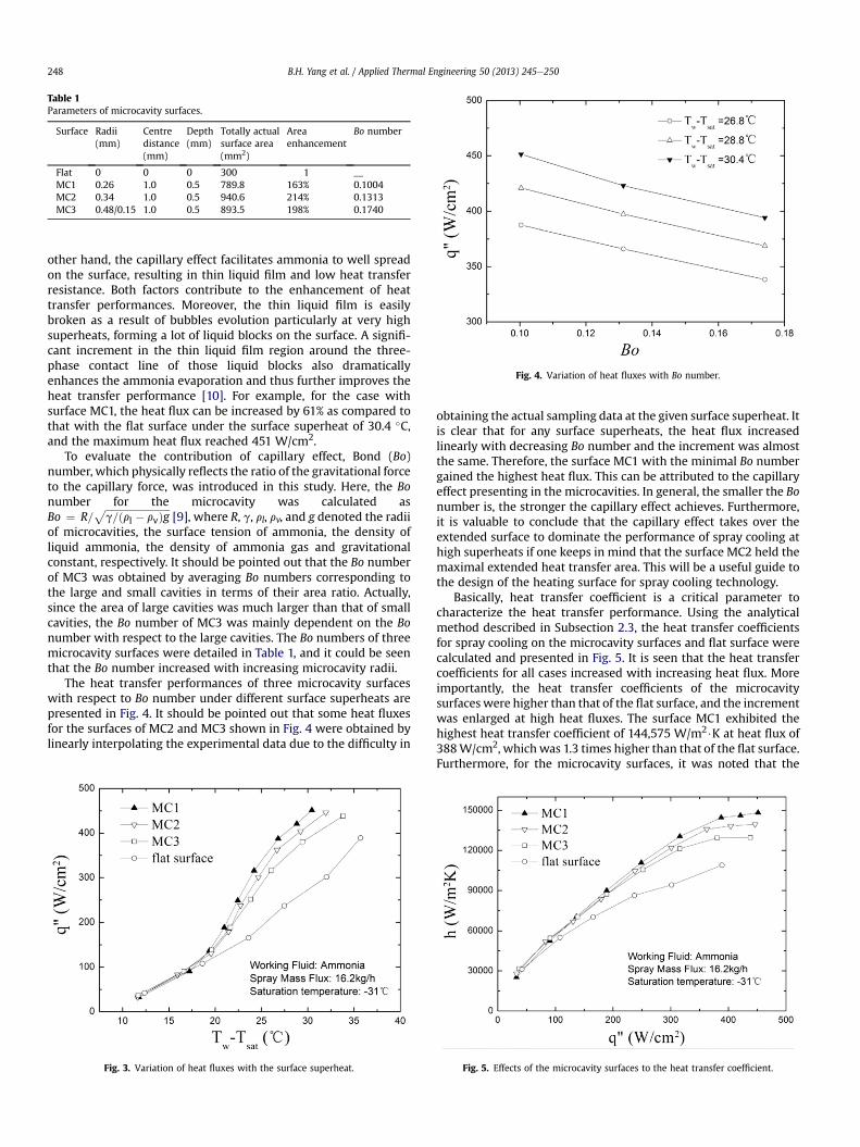
Table 1Parameters of microcavity surfaces.
Surface Radii(mm)
Centredistance(mm)
Depth(mm)
Totally actualsurface area(mm2)
Areaenhancement
Bo number
Flat 0 0 0 300 1 __MC1 0.26 1.0 0.5 789.8 163% 0.1004MC2 0.34 1.0 0.5 940.6 214% 0.1313MC3 0.48/0.15 1.0 0.5 893.5 198% 0.1740
Fig. 4. Variation of heat fluxes with Bo number.
B.H. Yang et al. / Applied Thermal Engineering 50 (2013) 245e250248
other hand, the capillary effect facilitates ammonia to well spreadon the surface, resulting in thin liquid film and low heat transferresistance. Both factors contribute to the enhancement of heattransfer performances. Moreover, the thin liquid film is easilybroken as a result of bubbles evolution particularly at very highsuperheats, forming a lot of liquid blocks on the surface. A signifi-cant increment in the thin liquid film region around the three-phase contact line of those liquid blocks also dramaticallyenhances the ammonia evaporation and thus further improves theheat transfer performance [10]. For example, for the case withsurface MC1, the heat flux can be increased by 61% as compared tothat with the flat surface under the surface superheat of 30.4 �C,and the maximum heat flux reached 451 W/cm2.
To evaluate the contribution of capillary effect, Bond (Bo)number, which physically reflects the ratio of the gravitational forceto the capillary force, was introduced in this study. Here, the Bonumber for the microcavity was calculated asBo ¼ R=
ffiffiffiffiffiffiffiffiffiffiffiffiffiffiffiffiffiffiffiffiffiffiffiffiffiffig=ðrl � rvÞg
p[9], where R, g, rl, rv, and g denoted the radii
of microcavities, the surface tension of ammonia, the density ofliquid ammonia, the density of ammonia gas and gravitationalconstant, respectively. It should be pointed out that the Bo numberof MC3 was obtained by averaging Bo numbers corresponding tothe large and small cavities in terms of their area ratio. Actually,since the area of large cavities was much larger than that of smallcavities, the Bo number of MC3 was mainly dependent on the Bonumber with respect to the large cavities. The Bo numbers of threemicrocavity surfaces were detailed in Table 1, and it could be seenthat the Bo number increased with increasing microcavity radii.
The heat transfer performances of three microcavity surfaceswith respect to Bo number under different surface superheats arepresented in Fig. 4. It should be pointed out that some heat fluxesfor the surfaces of MC2 and MC3 shown in Fig. 4 were obtained bylinearly interpolating the experimental data due to the difficulty in
Fig. 3. Variation of heat fluxes with the surface superheat.
obtaining the actual sampling data at the given surface superheat. Itis clear that for any surface superheats, the heat flux increasedlinearly with decreasing Bo number and the increment was almostthe same. Therefore, the surface MC1 with the minimal Bo numbergained the highest heat flux. This can be attributed to the capillaryeffect presenting in the microcavities. In general, the smaller the Bonumber is, the stronger the capillary effect achieves. Furthermore,it is valuable to conclude that the capillary effect takes over theextended surface to dominate the performance of spray cooling athigh superheats if one keeps in mind that the surface MC2 held themaximal extended heat transfer area. This will be a useful guide tothe design of the heating surface for spray cooling technology.
Basically, heat transfer coefficient is a critical parameter tocharacterize the heat transfer performance. Using the analyticalmethod described in Subsection 2.3, the heat transfer coefficientsfor spray cooling on the microcavity surfaces and flat surface werecalculated and presented in Fig. 5. It is seen that the heat transfercoefficients for all cases increased with increasing heat flux. Moreimportantly, the heat transfer coefficients of the microcavitysurfaces were higher than that of the flat surface, and the incrementwas enlarged at high heat fluxes. The surface MC1 exhibited thehighest heat transfer coefficient of 144,575 W/m2$K at heat flux of388W/cm2, which was 1.3 times higher than that of the flat surface.Furthermore, for the microcavity surfaces, it was noted that the
Fig. 5. Effects of the microcavity surfaces to the heat transfer coefficient.

Fig. 7. The surface temperature distribution over the MC1.
B.H. Yang et al. / Applied Thermal Engineering 50 (2013) 245e250 249
heat transfer coefficients were almost the same when the heat fluxwas below 200W/cm2. This is because the single-phase convectionstill dominates the whole heat transfer process at low and middleheat fluxes although the nucleate boiling starts to affect the heattransfer. However, with further increase in the heat flux, the heattransfer coefficient of the surface MC1 with the minimal micro-cavity radii gained the highest value of 148,245W/m2$K, whichwasabout 14% higher than that of the surface MC3 at the heat flux of451 W/cm2. As analyzed above, this is because that the nucleateboiling dominates the heat transfer in spray cooling process at highheat flux and the stronger capillary effect presenting in the smallermicrocavities enhances the heat transfer performance. The lowerthe Bo number, the higher the heat transfer coefficient. In summary,for the design of enhanced heat transfer surface with microcavitiesfor spray cooling at high heat flux, low Bo number is preferred tothe enhancement of spray cooling performance since the inducedcapillary effect plays a vital role in the heat transfer process.
3.2. Surface temperature of heat sinks
In the applications of high heat flux cooling techniques, not onlythe high heat flux must be ensured, but also a low surfacetemperature is required to ensure a stable operation of compo-nents. Fig. 6 shows the variation of surface temperature of differentheat sinks with the heat flux. Contrary to the flat surface on whichthe surface temperature increased rapidly with increasing heatflux, all the microcavity surfaces exhibited much lower surfacetemperatures. Even at a especially high heat flux of 400W/cm2, thesurface temperatures of all the microcavity surfaces were stillmaintained below 0 �C while the surface temperature of the flatsurface reached about 5 �C. This further proved that the addition ofmicrocavities to the heat sink significantly enhanced the spraycooling performance due to the extended surface and the capillaryeffect. Furthermore, it was also found that three microcavitysurfaces yielded almost the same surface temperature and thetemperatures increased quickly under lower heat fluxes (below100 W/cm2). While the growth in surface temperature was sloweddown once the heat transfer gradually changed from the single-phase convection to the nucleate boiling under high heat fluxes.Moreover, the temperature difference among three microcavitysurfaces was also increased with increasing heat flux, indicatingthat the capillary effect is more obvious at high heat fluxes. As
Fig. 6. Variation of surface temperatures with the heat flux.
a result, the surface MC1 with the lowest Bo number obtained thelowest surface temperature under high heat fluxes.
In addition to the requirements for high heat transfer coefficientand low surface temperature, the temperature uniformity of theheating surface is another critically important criterion to evaluatethe spray cooling performance. Uniform distribution of the surfacetemperature is beneficial to avoiding the occurrence of hot spot. Inthe present study, three temperature monitoring points, asdescribed in Subsection 2.3, were set in the heat sink to examine thetemperature distribution. As a representative, the temperaturedistribution on the surface MC1 under different heat fluxes wasgiven in Fig. 7. Clearly, a perfectly uniform temperature distributionwas shownwhen the heat flux was below 300 W/cm2, while a tinydeviation was presented at high heat flux. The reason can beattributed to the well-distributed microcavities along with inducedhigh heat transfer coefficient, resulting in uniformly spreading thinliquid film and enhanced heat transfer performance, hence theuniform temperature distribution. The temperature deviationshould be as a consequence of the instability resulting from thenucleate boiling at high heat fluxes. Nevertheless, the temperaturedeviation was still kept below �1.5 �C even at the high heat flux of420 W/cm2. Such temperature distribution is satisfactory for realapplications. Therefore, it can be concluded that the microcavitysurface can yield a high heat transfer coefficient and low surfacetemperaturewith uniformdistribution, revealing that suchdesign isone of the efficientmethods to boost the spraycooling performance.
4. Conclusion
Three microcavity surfaces were designed and fabricated toenhance the spray cooling performance with ammonia as coolant inthe present study. Experimental results showed that at low surfacesuperheats the microcavity surfaces output almost the same heattransfer performance as that on theflat surface since the heat transferwas mainly contributed by the single phase convection. The signifi-cant superiority of the microcavity surfaces over the flat surface wasexhibited at high surface superheats once the heat transfer wasdominated by the nucleate boiling, resulting in high heat transfercoefficient and uniform temperature distribution. Considering thatthe capillary effect resulted from themicrocavity structure played animportant role during the nucleate boiling, the effect ofBonumber onthe heat transfer was discussed for three microcavity surfaces. It isshown that a significant enhancement of the heat transfer perfor-mance was obtained at lower Bo number. The surface MC1 with thelowest Bo number of 0.1004 yielded the highest heat transfer coeffi-cient of 148,245 W/m2$K at the heat flux of 451 W/cm2 while it stillkept the surface temperature below 0 �C. Furthermore, a uniform

B.H. Yang et al. / Applied Thermal Engineering 50 (2013) 245e250250
temperature distribution was achieved on surface MC1 with devia-tion below �1.5 �C at the heat flux of 420 W/cm2.
Acknowledgements
Authors are grateful for the financial support of National Naturaland Science Foundation of China (No. 50906102); Nature ScienceFoundation of Chongqing(No. CSTC2011jjA90015); the ThirdStage of “211 Project”, Chongqing University (No.S-09101); theFundamental Research Funds for the Central Universities(CDJRC10150002),SRF for ROCS, SEM([2010]1561).
References
[1] M. Ghodbane, J.P. Holman, Experimental-study of spray cooling with Freon-113, Int. J. Heat Mass Transfer 34 (1991) 1163e1174.
[2] J.D. Yang, M.R. Pais, L.C. Chow, Critical heat flux limits in secondary gasatomized liquid spray cooling, Exp. Heat Transf. 6 (1993) 55e67.
[3] D.P. Rini, R.H. Chen, L.C. Chow, Bubble behavior and nucleate boiling heat transferin saturated FC-72 spray cooling, J. Heat Transf.-Trans. ASME 124 (2002) 63e72.
[4] M. Visaria, I. Mudawar, Theoretical and experimental study of the effects ofspray inclination on two-phase spray cooling and critical heat flux, Int. J. HeatMass Transfer 51 (2008) 2398e2410.
[5] L. Lin, R. Ponnappan, Heat transfer characteristics of spray cooling in a closedloop, Int. J. Heat Mass Transfer 46 (2003) 3737e3746.
[6] H. Bostanci, B.A. Saarloos, D.P. Rini, J.P. Kizito, L.C. Chow, Spray cooling withammonia on micro-structured surfaces, in: 2008 11th IEEE IntersocietyConference on Thermal and Thermomechanical Phenomena in ElectronicSystems, Vols. 1e3, IEEE, New York, 2008, pp. 290e295.
[7] J.S. Coursey, J.G. Kim, K.T. Kiger, Spray cooling of high aspect ratio openmicrochannels, J. Heat Transf.-Trans. ASME 129 (2007) 1052e1059.
[8] J. Yang, L.C. Chow, M.R. Pais, Nucleate boiling heat transfer in spray cooling,J. Heat Transfer 118 (1996) 668e671.
[9] C.C. Hsieh, S.C. Yao, Evaporative heat transfer characteristics of awater spray onmicro-structured silicon surfaces, Int. J. HeatMass Transfer 49 (2006) 962e974.
[10] B. Horacek, K.T. Kiger, J. Kim, Single nozzle spray cooling heat transfermechanisms, Int. J. Heat Mass Transfer 48 (2005) 1425e1438.
[11] J. Wendelstorf, K.H. Spitzer, R. Wendelstorf, Spray water cooling heat transferat high temperatures and liquid mass fluxes, Int. J. Heat Mass Transfer 51(2008) 4902e4910.
[12] M.R. Pais, L.C. Chow, E.T. Mahefkey, Surface-roughness and its effects on theheat-transfer mechanism in spray cooling, J. Heat Transf.-Trans. ASME 114(1992) 211e219.
[13] S. Toda, A study of mist cooling. II. Theory of mist cooling and its fundamentalexperiments, Heat Transf. Jpn. Res. 3 (1974) 1e4444.
[14] C. Bonacina, S. Del Giudice, G. Comini, Dropwise evaporation, J. Heat Transfer101 (1979) 441e446.
[15] L.C. Chow, M.S. Sehmbey, M.R. Pais, High Heat Flux Spray Cooling, vol. 8,Begell House, 1997, pp. 291e318.
[16] K.A. Estes, I. Mudawar, Comparison of two-phase electronic cooling using freejets and sprays, Trans. ASME J. Electron. Packag. 117 (1995) 323e332332.
[17] K.A. Estes, I. Mudawar, Correlation of Sauter mean diameter and critical heat-flux for spray cooling of small surfaces, Int. J. Heat Mass Transf. 38 (1995)2985e2996.
[18] B. Horacek, J. Kim, K.T. Kiger, Spray cooling using multiple nozzles: visuali-zation and wall heat transfer measurements, IEEE Trans. Device Mater. Reliab.4 (2004) 614e625.
[19] D.E. Tilton, C.L. Tilton, M.R. Pais, M.J. Morgan, High-flux Spray Cooling ina Simulated Multichip Module, vol. 206-2, Publ by ASME, San Diego, CA, USA,1992, pp. 73e79.
[20] L. Ortiz, J.E. Gonzalez, Experiments on steady-state high heat fluxes usingspray cooling, Exp. Heat Transf. 12 (1999) 215e233.
[21] C.M. Kendall, J.P. Holman, Spray Cooling Heat-transfer with Subcooled Tri-chlorotrifluoroethane (Freon-113) forVertical ConstantHeat FluxSurfaces (1996).
[22] R.H. Chen, L.C. Chow, J.E. Navedo, Effects of spray characteristics on criticalheat flux in subcooled water spray cooling, Int. J. Heat Mass Transf. 45 (2002)4033e4043.