heat exchanger accessories temperature control - series … accessories.pdf · heat exchanger...
TRANSCRIPT

54 55
Heat exchanger accessoriesTEMPErATUrE CONTrOL - SErIES 123W
May be used directly to control small electric motors etc using SINGLE phase power supply to maximum of 6 amps. Also for low volt (12 or 24) DC power supplies to maximum of 6 amps, thereafter a relay is required. For THREE phase power supplies a kit including a junction box with suitable relay is available.
The thermoswitches use an Australian made reliable “snap” action bimetallic disk type switch which is sealed for life inside a brass bulb well. Switch contacts are normally open and gold plated to provide long service life when operated in range specified. Lead is 32-1 cable with earth wire grounded to red brass bulb. Bulb has male 3/4” BSPP thread with O ring and retaining ring. Made to order thermoswitches with normally closed and / or longer cable and / or other temperatures available on request.
Switches are fixed temperature (not adjustable). Closing temperature is +/-2°C from close temp. Switch reopens at 8 to 10°C below close temp. Thermoswitch has enclosure rating IP66. Pressure rated 17 Bar.
Basic 123W sWitcHorder code Closing Temperature17/12463WNO 46°C17/12553WNO 55°C17/12653WNO 65°C
DYNACOOL
OILIN
OILOUT
AuxiliaryPort
23.1
38 75
3/4" BSPPO-Ring Connection
1 1/4" AFHexagon
37mm Swing
Cable Length1.4 metres
Enclosure IP65 To IEC 5298To DIN 40050
For three phase power supplies, the thermoswitches must be used in conjunction with a relay. The thermoswitches may be purchased with a junction box as a kit as listed below. The junction box has a relay and three position switch all preassembled for fast easy site installation by a certified electrician. A wiring diagram is provided on inside of junction box lid. Junction box enclosure rating is IP55. Use is limited to motors that take a maximum current of 6 Amps, from 3 phase 400/415 VAC 50/60Hz power supply. Contactor relay control coil is 240VAC, and current draw 125mA.
KIT with 123W SWITCH and JUNCTION BOX order code Closing Temperature 17/JB/123W/46 46°C 17/JB/123W/55 55°C 17/JB/123W/65 65°C
DYNACOOL AIr COOLED HEAT EXCHANGErAuxiliary Port Details for thermostat mounting
Heat Exchanger Auxiliary Reducer Model Port Size Bush (RYCO) VC4,5,6,7 & 8 3/4” BSPP None req DC31 & DC32 1 1/4” BSPP S102-2012 DC32S 3/4” BSPP None req DC33 & DC35 3/4” BSPP None req
Heat exchanger accessories3 PHASE THErMOSTATIC CONTrOL
All dimensions in mm unless noted otherwise 0-50 are ± 1. 50-1500 are ± 3.
acce
sso
ries

54 55
Heat exchanger accessoriesLOW VOLTAGE TEMPErATUrE CONTrOL - 12V AND 24V DC
General DescriPtion Used on 12 and 24 volt DC coolers. A self contained thermostatically controlled electric switch mounted in a steel bulb well for immersion in the hot process fluid. The bulb has a 1/2” BSPP external thread. The miniature differential switch is of the snap action type actuated at preset temperature by a bimetallic disk placed in close proximity to the end of the bulb well. The switch contacts are gold plated to ensure maximum capacity and long life. The switch is usually supplied with normally open contacts but is available to special order in normally closed configuration. A relay is required to prevent damage to switch contacts if current is more than 6 amps.
sPeciFications DC Current. 12 & 24 Volts 6 Amps.Temperature Range (Standard). Contacts close at 55°C +/-2°C temperature and have a differential of 8 to 10°C.Port Entry Nozzle requirements. Thread 1/2” BSPP to ISO 228/1-1982 or equivalent. Flat machined sealing face required.Pressure rating. 17 Bar (250 PSI).Bulb Material. Zinc plated steel. Rubber boot supplied
Thermoswitch OnlyPart number Description17/Dc55/Wno 1/2”BSPP Wet thermoswitch contacts close at 55°C17/Dc65/Wno 1/2”BSPP Wet thermoswitch contacts close at 65°C
relay Harness KitsPart number Cooler Model Description039.8.06142 Vc2,4,5,6 & 7 17/DC55/WNO switch, 24V relay and harness kit039.8.06143 Vc2,4,5,6 & 7 17/DC65/WNO switch, 24V relay and harness kit039.8.06172 Vc2,4,5,6 & 7 17/DC55/WNO switch, 12V relay and harness kit039.8.06173 Vc2,4,5,6 & 7 17/DC65/WNO switch, 12V relay and harness kit039.8.06369 Vc8 17/DC55/WNO switch, 24V relay and harness kit039.8.06370 Vc8 17/DC65/WNO switch, 24V relay and harness kit039.8.06371 Vc8 17/DC55/WNO switch, 12V relay and harness kit039.8.06372 Vc8 17/DC65/WNO switch, 12V relay and harness kitKits include a fuse, fuse holder, port adaptor, relay, wiring and fitting instructions.
13 40
1/2" BSPP
1 1/8" AF Hexagon32mm Swing
Rubber Boot
Fibrewasher
Wires aprox,220mm long
DYNACOOL HEAT EXCHANGErAuxiliary Port Details for thermostat
Model Auxiliary Reducer Port Size Bush (RYCO) TM20, TM40 1/2” BSPP None req VC2 1/2” BSPP None req VC4,5,6,7 & 8 3/4” BSPP S102-1208 DFM11, 12 & 22 3/4” BSPP S102-1208 DC31Y, DC32Y 1 1/4” BSPP S102-2012 DC32S 3/4” BSPP S102-1208
All dimensions in mm unless noted otherwise 0-50 are ± 1. 50-1500 are ± 3.
accessories
56 57
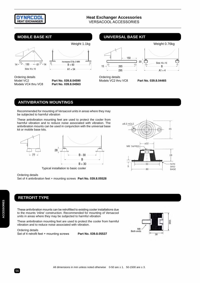
Heat exchanger accessoriesVErSACOOL ACCESSOrIES
B + 60130
A1 + 54Slots 16 x 10
Increases E By 3 MM14 1461
20
BA1 + 4
Slots 16 x 10
295
150
26515
moBile Base Kit UniVersal Base Kit
Ordering detailsModel VC2 Part no. 039.8.04590Models VC4 thru VC8 Part no. 039.8.04563
Ordering detailsModels VC2 thru VC8 Part no. 039.8.04465
Weight 1.1kg Weight 0.76kg
Recommended for mounting of Versacool units in areas where they may be subjected to harmful vibration
These antivibration mounting feet are used to protect the cooler from harmful vibration and to reduce noise associated with vibration. The antivibration mounts can be used in conjunction with the universal base kit or mobile base kits.
antiViBration moUntinGs
28
B - 30B
77
B + 30Typical installation to basic cooler
Ordering detailsSet of 4 antivibration feet + mounting screws Part no. 039.8.05528
These antivibration mounts can be retrofitted to existing cooler installations due to the mounts ‘inline’ construction. Recommended for mounting of Versacool units in areas where they may be subjected to harmful vibration
These antivibration mounting feet are used to protect the cooler from harmful vibration and to reduce noise associated with vibration.
Ordering detailsSet of 4 retrofit feet + mounting screws Part no. 039.8.05537
retroFit tYPe
All dimensions in mm unless noted otherwise 0-50 are ± 1. 50-1500 are ± 3.
acce
sso
ries

56 57
Heat exchanger accessoriesTHErMAL BYPASS ASSEMBLY
This thermal bypass valve is ideally suited for hydro-static drive circuits which require fast warm-up, control-led fluid temperature, and low return line back pressure. When installed in the return line of a hydraulic circuit that employs an oil cooler, this device will modulate fluid temperature by either shifting return line flow through the cooler, or bypassing directly to the reservoir. In ad-dition, a built-in pressure relief function automatically relieves excess pressure to the reservoir should the cooler become restricted and resultant pressure drop become too high for the cooler circuit.
Part no Shift temperature Part no Shift temperature 65/65654 38°C (100°F) 65/65656 60°C (140°F) 65/65655 49°C (120°F) 65/65657 71°C (160°F)
Dimensions - thermal Bypass PressUre DroP
moDe examPles
Based on Mobile DTE 26 oilNote: Pressure drop shown is added to relief valve crack pressure for total pressure drop.
orDerinG inFormation
Graphic SymbolCoolerReservoir
INLET
A A
INLET
10.7 (0.42" Dia2 Mounting holes
#16 SAE1 5/16-12UN-2B"O" ring Port(3 Places)
Tank Port
Cooler Port(CLR)
VIEW A-A
TANK
72.9(2.87")
47.8(1.88") 66.5
(2.62")137.4(5.41")
89.4(3.52")
0 10 20 30 40 50 60
80
60
40
20
FLOW - GPM
PSID
INLET PORT THRU TANK PORT@ 38C (100F) (300 SUS)
0 10 20 30 40 50 60
16
12
8
4
FLOW - GPM
PSID
INLET PORT THRU COOLER PORT@ 63C (145F) (110 SUS)
0 10 20 30 40 50 60
160
120
80
40
FLOW - GPM
INLET PORT OVERINTEGRAL RELIEF VALVE
@ 77C (170F) (78 SUS)
PSID
All dimensions in mm unless noted otherwise 0-50 are ± 1. 50-1500 are ± 3.
FeatUres:1. Operating Characteristics: A. Mode #1: At temperatures below the shift temperature oil flows from
inlet to tank port. B. Mode #2: At temperatures between the start of shift & full shift the
flow from the inlet port is divided between the cooler & tank ports. C. Mode #3: At temperatures above the full shift temperature inlet flow
is through cooler port. D. Mode #4: At temperatures above the full shift temperature the excess
pressure is relieved through the tank port.2. Standard Shift Temperatures: 100°F(38°C). 120°F (49°C) 140°F (60°C)
and 160°F (71 °C)3. Full Shift (Cooler Port Open) Temperature: Shift temp plus 25°F (14°C)4. Relief valve setting: 65 psi (4.5 bar). Consult factory for other settings.5. Maximum Operating Pressure: 250 psi (17 bar)6. Proof Pressure: 300 psi (21 bar)7. Minimum Burst Pressure: A. Up to the full shift temperature: 325 psi (22 bar) B. Above the full shift temperature: 600 psi (41 bar)8. Minimum Operating Temperature: -30°F (-34°C)9. Maximum Operating Temperature: Shift temperature plus 75°F (42°C)10. Maximum Flow Rating: 60 gpm (227 I/m)11. Leakage @ 250 psi (17 Bar) and 60 gpm (227 l/min) Inlet Flow: A. Cooler Port: 1. 0.5 gpm (2 I/m) maximum up to 5°F (3°C) before shift temp. 2. 1.0 gpm (4 I/m) maximum from 5°F (3°C) before shift to shift. B. Tank Port: 0.10 gpm (0.4 I/m) maximum12. Operating Fluid: Mineral base hydraulic fluids13. Construction: Aluminium die-cast housing.
accessories

58 59
• No external power source required.
• Opening point setting is simply adjusted by rotating screw on top of valve housing.
• Turning the valve clockwise will decrease the opening temperature.
• Turning the shaft counter clockwise will increase the opening temperature.
• Valves must be adjusted correctly after installation and whilst equipment is operating under normal conditions. Factory does not preset these valves.
• Opening point is adjustable within standard range shown, other ranges also available.
• Closing point is 2-3 degrees below opening point. Differential temp is not adjustable.
• Maximum recommended working pressure is 150 PSI (10 BAR).
• Not suitable for use in saltwater service.
• Bulb well recommended & available upon request as optional extra.
aPPlication: These water modulating valves regulate the flow of water to the heat exchanger. The valve opens when the temperature increases at the sensing bulb. Cooling rate is automatically varied to allow optimum oil temperature to be maintained. Water is conserved by reducing / stopping flow when minimal or no cooling is required
Heat exchanger accessoriesMODULATING WATEr VALVES AND BULB WELLS
Part Number Pipe Opening point Max. Flow Bulb Weight Sensing includes size# temp. range* temp. Max. size approx. Bulb Valve & Sensor (NPT) Min-Max (°C) limit (°C) (L/m) L x dia (mm) (Kg) Number
65/65293 1/2” 46 - 71 93 95 83x17.5 2.0 65/65293S 65/65127 3/4” 46 - 71 93 150 83x17.5 2.7 65/65293S 65/65128 1” 46 - 71 93 200 153x17.5 4.6 65/65128S 65/65146 1 1/4” 46 - 71 93 280 153x17.5 5.5 65/65128S
Recommended bulb well part number is 65/65141 for all above valves. A slightly shorter length pocket is available for the 83mm long bulbs, part number is 65/65140. Factory recommends the longer bulb well to provide additional protection. # See form DC 107 for larger size valves. * Lower opening point range available if necessary (24 - 57 deg C). Valve is fully open 20°C above opening point.
sPeciFications
oriFice PlUG.All valves are supplied with a drilled & tapped female by-pass hole inside the regulator body. A solid plug is installed in this hole for 100% shut off. Each valve is also supplied with a drilled orifice plug, packed in a envelope for field installation, if continuous minimum flow is required. The 1/2” & 3/4” valves use a plug with a 1.6mm orifice diameter, the 1’ & 1 1/4” valves have a plug with a 2.4mm diameter.
acce
sso
ries

58 59
Heat exchanger accessoriesMODULATING WATEr VALVES AND BULB WELLS
materials of constrUction.VALVE - Body ....................3/8”, 1/2” and 3/4” - Cast Brass 1” through 2 1/2” - Cast Iron Valve disk.............Buna N Disk holder ...........Brass Valve seat ............Aluminium Bronze Diaphragms .........Nylon Reinforced Buna NCAPILLArY TUBE ..............Copper in Brass sheathSENSING BULB ..................CopperBULB WELL ........................Brass or brass & copper
A
B
C
D
E
F
L
NM
32
1/2" NPT InternalThread
Armoured capillary tube is 1.83 meters longwith outside diameter of 6mm
3/4" BSPP ExternalThread
¯21
¯17SENSING BULB
BULB WELL
1/2" NPT
All dimensions in millimetres. Tolerance +/- 0.5 mm
NOT TO SCALE
All dimensions in mm unless noted otherwise 0-50 are ± 1. 50-1500 are ± 3.
ValVe POrTS A B C D E F L BUlB Well m N Part no. NPT Part No
65/65293 1/2” 83 178 86 47 38 10 83 65/65141 185 160 65/65127 3/4” 90 189 96 52 44 10 83 65/65140 115 88-90 65/65128 1” 123 259 139 67 51 13 15 Approx. weight 0.5kgs 65/65146 1 1/4” 124 269 119 67 60 13 152
accessories

• Flows up to 490 L/min
• Standard Ports 2” NPT (Opt. 1/2”, 3/4”, 1” & 1 1/2”)
• Flanged Ports Optional 3”, 4” & 6”
• Opening Temp range from 21° to 102° C.• Max. Operating Pressure of 8 Bar (115 PSI).
97
248
90 73
By-pass port
Heat exchanger port
Inlet Port
B
HeatSource
Pump
AB
C
DYNACOOLHeat Exchanger
HeatSource
Pump
AB
C
C
A
2” NPT All ports female thread.Warning: 0.5 Bar (7 PSI) ∆P across valve Ports
General Description Three way thermostatic valves use the principle of expanding wax. A self contained power ele-ment activates a stainless steel sliding valve which provides a positive three way action. All temperature settings are factory set. Elements are field replaceable, hence valves can be altered to operate at a different temperature range or refitted with new elements of the same setting.During cold start up, total flow is through the by-pass port. Once the fluid temperature reaches the opening point, the valve begins to open and flow to the heat exchanger supply port begins. As the temperature rises the valve shifts further allowing more flow through the heat exchanger supply port and less to the by-pass port. When the fully shifted tem-perature is reached the valve is fully stroked and all flow is directed to the heat exchanger port.Valves can be used for oil or fresh water serviceHousing - Cast Iron (optional steel or bronze)
o-rings - Viton (optional, Buna N)Valve - Alloy steel.applications Three way thermostatic valves may be in-stalled for either “mixing” or “diverting” modes of operation and can be mounted in any plane and with port orientated in any direction.When installing in mixing mode, the valve must be located on the cold side of the application. Hot liquid will be mixed with cooled fluid to discharge liquid at proper temperature. Select a valve with opening point at, or just above, the minimum desired oil operating temperature.For diverting mode, the valve must be installed on the hot side of the application. Cold liquid will be bypassed until the system warms up, then flow is directed to the heat ex-changer. Select a valve with full shift point at, or just below, the maximum desired oil operating temperature.
Code Part Type 66041 Complete valve 67818 Element only
tHree - WaY orDerinG coDes65/ 66041 / 43/54
Heat exchanger accessoriesTHrEE - WAY THErMOSTATIC VALVE
MIXING Applications DIVERTING Applications
PrESSUrE DrOP TABLE (Bar) Flow Oil Viscosity (cSt) L/min 255 180 115 85 water 190 0.12 0.12 0.10 0.08 0.07 285 0.24 0.21 0.17 0.15 0.13 380 0.42 0.38 0.33 0.30 0.26 475 - - - - 0.44max. flow (l/min) 405 425 445 465 490
Code Opening Fully Point °C Shifted °C 21/24 21 24 29/41 29 41 38/47 38 47 43/54* 43 54 51/60 51 60 57/66* 57 66 63/71 63 71 66/74 66 74 68/78 68 78 71/79 71 79 74/82 74 82 79/88* 79 88 87/98 87 98 93/102 93 102
* common stocked settings
2” NPT model weights 9 kg
60 61
acce
sso
ries