hdkbr info 2013., broj 9
TRANSCRIPT
NDT WEEK in ZAGREB
Godina / Year 2013 ZAGREB Svibanj/ May Broj / No 9
7-12 October 2013.
Izdavač: HDKBR Hrvatsko društvo za kontrolu bez razaranjaPublisher: CrSNDT Th e Croatian Society for Non Destructive TestingDirektor / Director: mr.sc. Miro Džapo
Tajništvo/Secretariat:HIS, Petra Berislavića 6. 10000 Zagreb, RHTel: +385 (01) .....Fax:+385 (01).....E-mail: [email protected], Website: www.hdkbr.hr Kontakt/Contact: Tijana Gadža
Urednik / Editor-in-chif:prof.dr.sc.Vjera KrsteljBerislavićeva 6HR-10000 Zagreb, CroatiaTel: + 385 1 48 80 985Email: [email protected]
Uredništvo, tehn/Editorial, tech.mr. sc. Irena Leljak mr.sc. Ivan Smiljanić
Lektor / LectorMarina Manucci, prof. Davor Nikolić, prof.
Priprema za tisak/Production:Sandro Bura
Sadržaj / Content
Poruka predsjednice /A Message from the President Ivana Banjad Pečur: PRIMJENA NERAZORNIH ISPITIVANJA u GRAĐEVINARSTVU
Radovi održani na savjetovanju MATEST 2011:Biljana TANATAREC,Nenad NIKOLIĆ;AKREDITACIJA LABORATORIJA, NORME, ZAKONI i PROPISI EUROPSKE UNIJE José P. SOUSA, Francisco DEMONY, Nuno PEDROSA,Telmo G. SANTOS, Pedro VILAÇA, Luísa QUINTINO;DEVELOPMENT of AUTOMATIC SYSTEMS for NDT INSPECTION of WHEELS and PROPELLER BLADES of AIRPLANES Predstavljamo vam:Intervju: Goran SofronićSiegfried VogelbacherPREVENTIVE MAINTENANCE: FUNCTION and ADDED VALUE of PREVENTIVE THERMOGRAPHIC MEASUREMENTS in the FRAMEWORK of INDUSTRIAL MAINTENANCE
NDT WEEK in ZAGREB
Th e Preliminary Program: CERTIFICATION 2013 HDKBR Centar za obrazovanje HDKBR Centar za certifi kaciju
Seminar: Upravljanje rizikom & kontrola kvalitete temeljena na procjeni rizika
Pročitali smo za vas ToFD ISPITIVANJE FAZNIM SONDAMA
HDKBR Info izlazi četiri puta godišnje/ distribucija 300 kom/broj CrSNDT journal is published four times a year/circulation 300 each journal Godišnja pretplata 300 kn 4 issues per year 40 Euro Časopis je besplatan za članove HDKBR-a Th e yournal is free for CrSNDT members HDKBR Info možete pratiti na www.hdkbr.hrAn online version is available
DOSTAVA PRILOGAHDKBR poziva članove i sve koji imaju materijale interesantne čitateljima ovog časopisa da ponude priloge. Znanstveni i stručni radovi će biti recenzirani od strane međunarodno priznatih eksperata. Za reprodukciju publiciranih radova i izvadaka treba osigurati dozvolu. Tekstovi i mišljenja autora u časopisu ne moraju biti u suglasju sa stavovima HDKBR-a i uredništva. Uredništvo ne nosi odgovornost za pogreške i propuste autora radova.
PAPER SUBMISSIONCrSNDT invites contributions that will be interesting for readers of HDKBR info Journal. Technical papers submitted are peer-reviewed by an Internationaly recog-nised experts. Permition should be obtained for reproduction of individual artlices and extracts.the Articles and views expressed in the publication are not necessarily in line with CrSNDT, editor and editorial. No liability is accepted for errors or omis-sion. OGLAŠAVANJE/ADVERTISEMENTCijena oglašavanja/Th e cost for advertising is:
Stranica/Page in yournal Cijena za 4 broja /Cost for 4 numbers per year
Zadnja/Th e last page(cover page A4 size)
8000 kn 1080 Euro or 1380 $ (US)
Unutarnja/Inside pages (A4 size) 4000 kn 540 Euro or 690 $ (US)
Unutarnja/Inside pages(A4/2 size; half page)
2000 kn 270 Euro or 395 $ (US)
Cijena oglasa u samo jednom broju iznosi pola cijene godišnjeg oglašavanja. Th e price of advertisement published (in only one journal number) is half of the yearly cost.
1
2-6
7-9
11-18
19-21
29
32
22-24
25
30-31
28
Prof. Vjera Krstelj, Ph.D.
HDKBR Info izlazi četiri puta godišnje/ distribucija 300 kom/broj CrSNDT journal is published four times a year/circulation 300 each journal Godišnja pretplata 300 kn 4 issues per year 40 Euro Časopis je besplatan za članove HDKBR-a Th e yournal is free for CrSNDT members HDKBR Info možete pratiti na www.hdkbr.hrAn online version is available
DOSTAVA PRILOGAHDKBR poziva članove i sve koji imaju materijale interesantne čitateljima ovog časopisa da ponude priloge. Znanstveni i stručni radovi će biti recenzirani od strane međunarodno priznatih eksperata. Za reprodukciju publiciranih radova i izvadaka treba osigurati dozvolu. Tekstovi i mišljenja autora u časopisu ne moraju biti u suglasju sa stavovima HDKBR-a i uredništva. Uredništvo ne nosi odgovornost za pogreške i propuste autora radova.
PAPER SUBMISSIONCrSNDT invites contributions that will be interesting for readers of HDKBR info Journal. Technical papers submitted are peer-reviewed by an Internationaly recog-nised experts. Permition should be obtained for reproduction of individual artlices and extracts.the Articles and views expressed in the publication are not necessarily in line with CrSNDT, editor and editorial. No liability is accepted for errors or omis-sion. OGLAŠAVANJE/ADVERTISEMENTCijena oglašavanja/Th e cost for advertising is:
Stranica/Page in yournal Cijena za 4 broja /Cost for 4 numbers per year
Zadnja/Th e last page(cover page A4 size)
8000 kn 1080 Euro or 1380 $ (US)
Unutarnja/Inside pages (A4 size) 4000 kn 540 Euro or 690 $ (US)
Unutarnja/Inside pages(A4/2 size; half page)
2000 kn 270 Euro or 395 $ (US)
Cijena oglasa u samo jednom broju iznosi pola cijene godišnjeg oglašavanja. Th e price of advertisement published (in only one journal number) is half of the yearly cost.
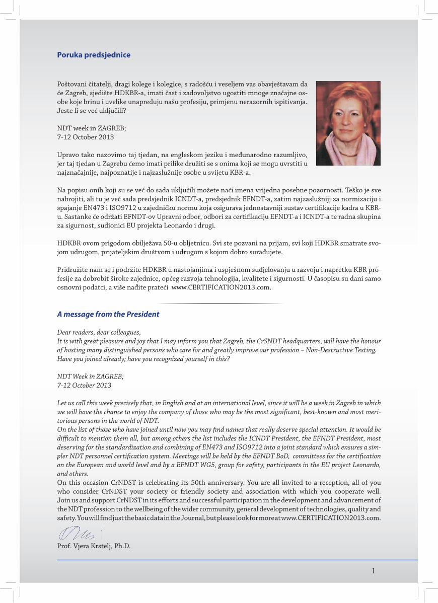
Poštovani čitatelji, dragi kolege i kolegice, s radošću i veseljem vas obavještavam da će Zagreb, sjedište HDKBR-a, imati čast i zadovoljstvo ugostiti mnoge značajne os-obe koje brinu i uvelike unapređuju našu profesiju, primjenu nerazornih ispitivanja.Jeste li se već uključili?
NDT week in ZAGREB;7-12 October 2013
Upravo tako nazovimo taj tjedan, na engleskom jeziku i međunarodno razumljivo, jer taj tjedan u Zagrebu ćemo imati prilike družiti se s onima koji se mogu uvrstiti u najznačajnije, najpoznatije i najzaslužnije osobe u svijetu KBR-a.
Na popisu onih koji su se već do sada uključili možete naći imena vrijedna posebne pozornosti. Teško je sve nabrojiti, ali tu je već sada predsjednik ICNDT-a, predsjednik EFNDT-a, zatim najzaslužniji za normizaciju i spajanje EN473 i ISO9712 u zajedničku normu koja osigurava jednostavniji sustav certifi kacije kadra u KBR-u. Sastanke će održati EFNDT-ov Upravni odbor, odbori za certifi kaciju EFNDT-a i ICNDT-a te radna skupina za sigurnost, sudionici EU projekta Leonardo i drugi.
HDKBR ovom prigodom obilježava 50-u obljetnicu. Svi ste pozvani na prijam, svi koji HDKBR smatrate svo-jom udrugom, prijateljskim društvom i udrugom s kojom dobro surađujete.
Pridružite nam se i podržite HDKBR u nastojanjima i uspješnom sudjelovanju u razvoju i napretku KBR pro-fesije za dobrobit široke zajednice, općeg razvoja tehnologija, kvalitete i sigurnosti. U časopisu su dani samo osnovni podatci, a više nađite prateći www.CERTIFICATION2013.com.
A message from the President
Dear readers, dear colleagues,It is with great pleasure and joy that I may inform you that Zagreb, the CrSNDT headquarters, will have the honour of hosting many distinguished persons who care for and greatly improve our profession – Non-Destructive Testing.Have you joined already; have you recognized yourself in this?
NDT Week in ZAGREB;7-12 October 2013
Let us call this week precisely that, in English and at an international level, since it will be a week in Zagreb in which we will have the chance to enjoy the company of those who may be the most signifi cant, best-known and most meri-torious persons in the world of NDT.On the list of those who have joined until now you may fi nd names that really deserve special attention. It would be diffi cult to mention them all, but among others the list includes the ICNDT President, the EFNDT President, most deserving for the standardization and combining of EN473 and ISO9712 into a joint standard which ensures a sim-pler NDT personnel certifi cation system. Meetings will be held by the EFNDT BoD, committees for the certifi cation on the European and world level and by a EFNDT WG5, group for safety, participants in the EU project Leonardo, and others.On this occasion CrNDST is celebrating its 50th anniversary. You are all invited to a reception, all of you who consider CrNDST your society or friendly society and association with which you cooperate well.Join us and support CrNDST in its eff orts and successful participation in the development and advancement of the NDT profession to the wellbeing of the wider community, general development of technologies, quality and safety. You will fi nd just the basic data in the Journal, but please look for more at www.CERTIFICATION2013.com.
Poruka predsjednice
1
2
PRIM
JEN
A N
ERAZ
ORN
IH IS
PITI
VAN
JA U
GRA
ĐEV
INAR
STVU
PRIMJENA NERAZORNIH ISPITIVANJA U GRAĐEVINARSTVU
prof.dr.sc.Ivana Banjad Pečur
APPLICATION OF NON-DESTRUCTIVE TESTING IN CIVIL ENGINEERING
Summary
Testing properties of materials and structures using non-destructive testing today it is an everyday necessity in modern the construction industry. Mostcommonly used methods of non-destructive test-ing of reinforced concrete structures are presented in the paper. Some of these methods are: visual inspection, Schmidt hammer, ultrasound, rebar detection system, galvanostatic pulse measurements technique and air permeability. For each method are given the main features and the possibility to use a certainmethod to determine the specific properties of materials and structures.
Key words: non-destructive testing, visual inspection, Schmidt hammer,ultrasound, properties of durability
1. UVOD
Poput ostalih tehničkih područja građevinarstvo ko-risti ispitivanja kako bi se došlo do novih spoznaja o građevinama i materijalima od kojih su te građevine izrađene. Rezultati tih ispitivanja osim što služe kao izvor novih spoznaja, koriste se kao kontrola postig-nute kvalitete tijekom izvedbe građevine, te kao kontrola promjene svojstava tijekom uporabnog vijeka. Sama ispitivanja prema načinu djelovanja na materijal/konstrukciju mogu biti s razaranjem, polurazaranjem i nerazorna. Nerazorna ispitivanja imaju višestruke prednosti u odnosu na ona s razaranjem: moguće je ponavljanje ispitivanja na istom uzorku ili mjestu konstrukcije, ispitivanja istog uzorka tijekom uporabnog vijeka, ispitivanje većeg broja uzoraka odnosno veći broj mjernih mjesta na konstrukciji, ispitivanje istog uzorka ili istog mjernog mjesta na konstrukciji s više različitih metoda. Ovo posljednje iznimno je važno kod kompozitnih materijala (kao što je be-ton) u svrhu kontrole kvalitete rezultata. Nedosta-tak nerazornih ispitivanja jest u tome što je za in-terpretaciju rezultata ispitivanja potrebno iskustvo te je potrebno stručno i iskusno osoblje.U građevinarstvu se nerazorna ispitivanja koriste više desetljeća, a neka suvremenija ispitivanja trajnos-nih svojstava materijala razvijena su u posljednjih
20-30 godina. Svrha provođenja ovih ispitivanja: znanstvena istraživanja, kontrolna ispitivanja ti-jekom proizvodnje i kontrolna ispitivanja tijekom eksploatacije.
U ovom članku biti će prikazana nerazorna ispi-tivanja koja se koriste kod pregleda armiranobe-tonskih građevina. Najčešća svrha tih ispitivanja jest određivanje stanja betona i čelične armature ugrađenih u konstrukciju u različitim starostima građevine. Uz to, nerazorna ispitivanja se koriste i u svrhu kontrole kvalitete materijala tijekom izvedbe konstrukcije.
2. VIZUALNI PREGLED
Prva i osnovna metoda koja se koristi kod pregleda armiranobetonskih (AB) građevina ili za kontrolu građevnih proizvoda kod ugradnje jest vizualni pregled. U normama i specifikacijama za betonske radove navedeno je da se dodatna ispitivanja svo-jstava rade ako je uočeno ili se sumnja u zadovoljen-je pojedinih zahtjeva kvalitete. Za postojeće veće AB - građevine, kao što su na primjer mostovi, prop-isani su obvezni periodički pregledi. Tako se redovni pregled mostova radi svakih 5 godina, a taj pregled
3
PRIM
JEN
A N
ERAZ
ORN
IH IS
PITI
VAN
JA U
GRA
ĐEV
INAR
STVU
uključuje vizualni pregled kao nužnu metodu za otkrivanje nedostataka i oštećenja na površini AB - elemenata konstrukcije. Vizualnim pregledom određuju se mjesta na konstrukciji s različitim vrsta-ma oštećenja kao što su mjesta segregacije betona, zračnih pora na površini betona, pojava pukotina (s bilježenjem širine pukotine), boja hrđe na površini, izluživanje betona, mrvljenje i odlamanje betona, otpadanje zaštitnog sloja betona do armature. Na temelju snimanja oštećenja radi se vizualna kat-egorizacija na način da se za svaki pojedini element konstrukcije kategorizira odnosno da se odrede postoci oštećene površine pojedinog elementa koji spadaju u određenu kategoriju u odnosu na uku-pnu površinu elementa. Kod nas je uobičajeno da se kategorizacija radi prema DIN 1076, smjernice RI-EBW-Pruf 88, a u Tablici 1 prikazana je kategori-zacija oštećenja.
K a te g o r i j e oštećenja Opis
0 Nema oštećenja
1 Manja oštećenja kao posljedica izvedbe
2 Manja oštećenja kao posljedica eksploatacije
3Oštećenja koja dugoročno
smanjuju trajnost građevine i potreban je popravak
4
Oštećenja koja u dogledno vrijeme mogu smanjiti
pouzdanost građevine i popravak je odmah potreban
5
Oštećenja koja predstavljaju veću opasnost za sigurnost građevine. Potrebna je hitna intervencija, a
prema potrebi i ograničenje i zatvaranje prometa.
Tablica 1. Kategorizacija oštećenja površine betona
Uz tablicu u kojoj su dani postoci oštećenja u pojedi-noj kategoriji za sve elemente konstrukcije daju se još i nacrti s razvijenim površinama svih elemenata s ucrtanim mjestima oštećenja prema vrsti oštećenja (npr. segregacija, boja hrđe, pukotine, odlamanja, ...). Prilikom provođenja vizualnog pregleda koriste se i druga pomagala za lakše uočavanje oštećenja: fotoaparat (za izradu fotodokumentacije), defek-toskop za pregled teže dostupnih mjesta (npr. kod ležajeva na stupovima ili upornjacima), čekić za otkrivanje odlamanja ili postojanje šupljina is-pod površine betona, mikroskop i povećalo za određivanje širine pukotina. Za preglede elemenata pod vodom koriste se roboti s daljinskim upravljan-jem i kamerom za podvodno snimanje.
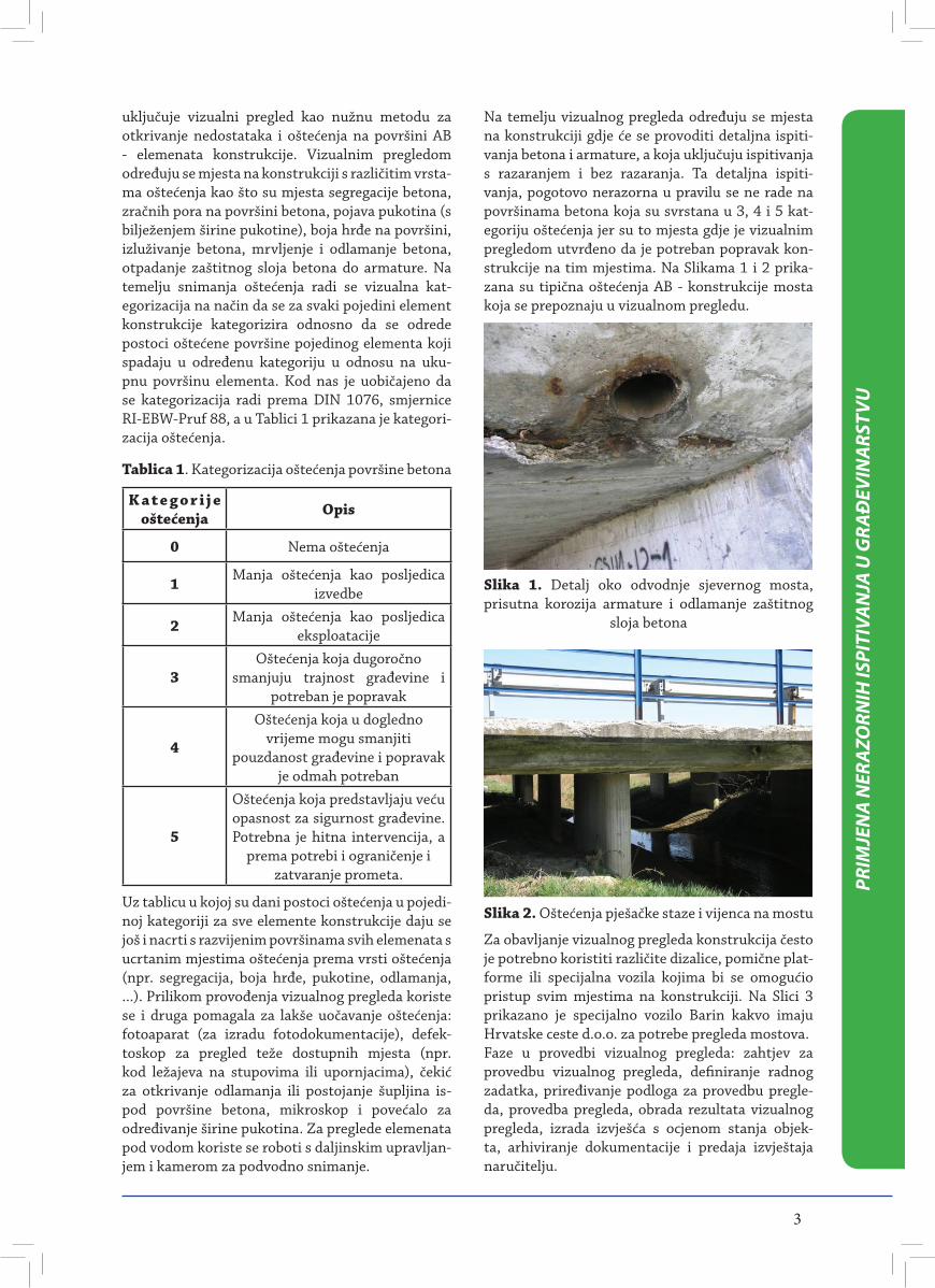
Na temelju vizualnog pregleda određuju se mjesta na konstrukciji gdje će se provoditi detaljna ispiti-vanja betona i armature, a koja uključuju ispitivanja s razaranjem i bez razaranja. Ta detaljna ispiti-vanja, pogotovo nerazorna u pravilu se ne rade na površinama betona koja su svrstana u 3, 4 i 5 kat-egoriju oštećenja jer su to mjesta gdje je vizualnim pregledom utvrđeno da je potreban popravak kon-strukcije na tim mjestima. Na Slikama 1 i 2 prika-zana su tipična oštećenja AB - konstrukcije mosta koja se prepoznaju u vizualnom pregledu.
Slika 1. Detalj oko odvodnje sjevernog mosta, prisutna korozija armature i odlamanje zaštitnog
sloja betona
Slika 2. Oštećenja pješačke staze i vijenca na mostu
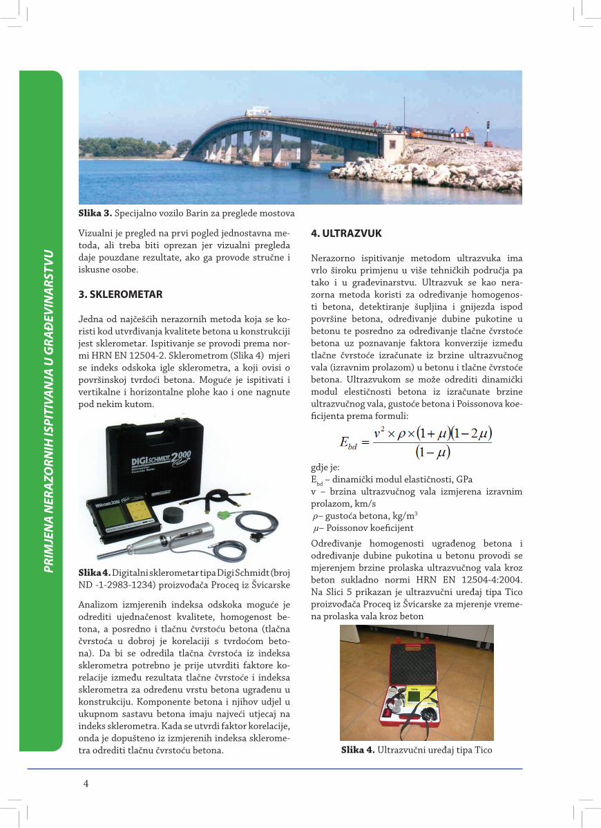
Za obavljanje vizualnog pregleda konstrukcija često je potrebno koristiti različite dizalice, pomične plat-forme ili specijalna vozila kojima bi se omogućio pristup svim mjestima na konstrukciji. Na Slici 3 prikazano je specijalno vozilo Barin kakvo imaju Hrvatske ceste d.o.o. za potrebe pregleda mostova.Faze u provedbi vizualnog pregleda: zahtjev za provedbu vizualnog pregleda, definiranje radnog zadatka, priređivanje podloga za provedbu pregle-da, provedba pregleda, obrada rezultata vizualnog pregleda, izrada izvješća s ocjenom stanja objek-ta, arhiviranje dokumentacije i predaja izvještaja naručitelju.
4
PRIM
JEN
A N
ERAZ
ORN
IH IS
PITI
VAN
JA U
GRA
ĐEV
INAR
STVU
Vizualni je pregled na prvi pogled jednostavna me-toda, ali treba biti oprezan jer vizualni pregleda daje pouzdane rezultate, ako ga provode stručne i iskusne osobe.
3. SKLEROMETAR
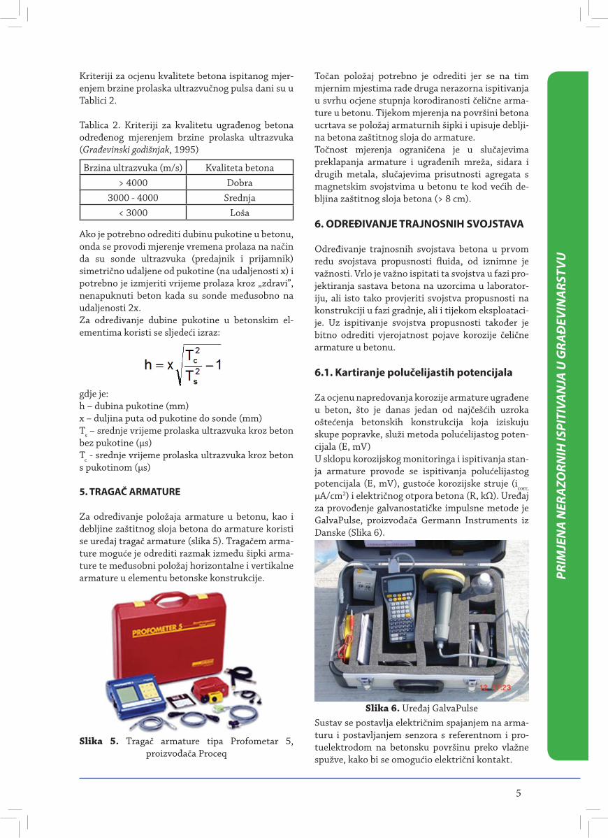
Jedna od najčešćih nerazornih metoda koja se ko-risti kod utvrđivanja kvalitete betona u konstrukciji jest sklerometar. Ispitivanje se provodi prema nor-mi HRN EN 12504-2. Sklerometrom (Slika 4) mjeri se indeks odskoka igle sklerometra, a koji ovisi o površinskoj tvrdoći betona. Moguće je ispitivati i vertikalne i horizontalne plohe kao i one nagnute pod nekim kutom.
Slika 3. Specijalno vozilo Barin za preglede mostova
Slika 4. Digitalni sklerometar tipa Digi Schmidt (broj ND -1-2983-1234) proizvođača Proceq iz Švicarske
4. ULTRAZVUK
Nerazorno ispitivanje metodom ultrazvuka ima vrlo široku primjenu u više tehničkih područja pa tako i u građevinarstvu. Ultrazvuk se kao nera-zorna metoda koristi za određivanje homogenos-ti betona, detektiranje šupljina i gnijezda ispod površine betona, određivanje dubine pukotine u betonu te posredno za određivanje tlačne čvrstoće betona uz poznavanje faktora konverzije između tlačne čvrstoće izračunate iz brzine ultrazvučnog vala (izravnim prolazom) u betonu i tlačne čvrstoće betona. Ultrazvukom se može odrediti dinamički modul elestičnosti betona iz izračunate brzine ultrazvučnog vala, gustoće betona i Poissonova koe-ficijenta prema formuli:
Analizom izmjerenih indeksa odskoka moguće je odrediti ujednačenost kvalitete, homogenost be-tona, a posredno i tlačnu čvrstoću betona (tlačna čvrstoća u dobroj je korelaciji s tvrdoćom beto-na). Da bi se odredila tlačna čvrstoća iz indeksa sklerometra potrebno je prije utvrditi faktore ko-relacije između rezultata tlačne čvrstoće i indeksa sklerometra za određenu vrstu betona ugrađenu u konstrukciju. Komponente betona i njihov udjel u ukupnom sastavu betona imaju najveći utjecaj na indeks sklerometra. Kada se utvrdi faktor korelacije, onda je dopušteno iz izmjerenih indeksa sklerome-tra odrediti tlačnu čvrstoću betona.
gdje je:Ebd – dinamički modul elastičnosti, GPav – brzina ultrazvučnog vala izmjerena izravnim prolazom, km/s ρ– gustoća betona, kg/m3
µ– Poissonov koeficijent
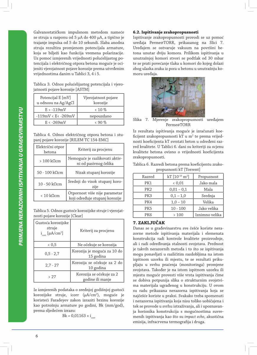
Određivanje homogenosti ugrađenog betona i određivanje dubine pukotina u betonu provodi se mjerenjem brzine prolaska ultrazvučnog vala kroz beton sukladno normi HRN EN 12504-4:2004. Na Slici 5 prikazan je ultrazvučni uređaj tipa Tico proizvođača Proceq iz Švicarske za mjerenje vreme-na prolaska vala kroz beton
Slika 4. Ultrazvučni uređaj tipa Tico
5
PRIM
JEN
A N
ERAZ
ORN
IH IS
PITI
VAN
JA U
GRA
ĐEV
INAR
STVU
Kriteriji za ocjenu kvalitete betona ispitanog mjer-enjem brzine prolaska ultrazvučnog pulsa dani su u Tablici 2.
Tablica 2. Kriteriji za kvalitetu ugrađenog betona određenog mjerenjem brzine prolaska ultrazvuka (Građevinski godišnjak, 1995)
Brzina ultrazvuka (m/s) Kvaliteta betona> 4000 Dobra
3000 - 4000 Srednja< 3000 Loša
Ako je potrebno odrediti dubinu pukotine u betonu, onda se provodi mjerenje vremena prolaza na način da su sonde ultrazvuka (predajnik i prijamnik) simetrično udaljene od pukotine (na udaljenosti x) i potrebno je izmjeriti vrijeme prolaza kroz „zdravi”, nenapuknuti beton kada su sonde međusobno na udaljenosti 2x.Za određivanje dubine pukotine u betonskim el-ementima koristi se sljedeći izraz:
gdje je:h – dubina pukotine (mm)x – duljina puta od pukotine do sonde (mm)Ts – srednje vrijeme prolaska ultrazvuka kroz beton bez pukotine (μs)Tc - srednje vrijeme prolaska ultrazvuka kroz beton s pukotinom (μs)
5. TRAGAČ ARMATURE
Za određivanje položaja armature u betonu, kao i debljine zaštitnog sloja betona do armature koristi se uređaj tragač armature (slika 5). Tragačem arma-ture moguće je odrediti razmak između šipki arma-ture te međusobni položaj horizontalne i vertikalne armature u elementu betonske konstrukcije.
Slika 5. Tragač armature tipa Profometar 5, proizvođača Proceq
Točan položaj potrebno je odrediti jer se na tim mjernim mjestima rade druga nerazorna ispitivanja u svrhu ocjene stupnja korodiranosti čelične arma-ture u betonu. Tijekom mjerenja na površini betona ucrtava se položaj armaturnih šipki i upisuje deblji-na betona zaštitnog sloja do armature.Točnost mjerenja ograničena je u slučajevima preklapanja armature i ugrađenih mreža, sidara i drugih metala, slučajevima prisutnosti agregata s magnetskim svojstvima u betonu te kod većih de-bljina zaštitnog sloja betona (> 8 cm).
6. ODREĐIVANJE TRAJNOSNIH SVOJSTAVA
Određivanje trajnosnih svojstava betona u prvom redu svojstava propusnosti fluida, od iznimne je važnosti. Vrlo je važno ispitati ta svojstva u fazi pro-jektiranja sastava betona na uzorcima u laborator-iju, ali isto tako provjeriti svojstva propusnosti na konstrukciji u fazi gradnje, ali i tijekom eksploataci-je. Uz ispitivanje svojstva propusnosti također je bitno odrediti vjerojatnost pojave korozije čelične armature u betonu.
6.1. Kartiranje polučelijastih potencijala
Za ocjenu napredovanja korozije armature ugrađene u beton, što je danas jedan od najčešćih uzroka oštećenja betonskih konstrukcija koja iziskuju skupe popravke, služi metoda polućelijastog poten-cijala (E, mV)U sklopu korozijskog monitoringa i ispitivanja stan-ja armature provode se ispitivanja polućelijastog potencijala (E, mV), gustoće korozijske struje (icorr, μA/cm2) i električnog otpora betona (R, kΩ). Uređaj za provođenje galvanostatičke impulsne metode je GalvaPulse, proizvođača Germann Instruments iz Danske (Slika 6).
Slika 6. Uređaj GalvaPulseSustav se postavlja električnim spajanjem na arma-turu i postavljanjem senzora s referentnom i pro-tuelektrodom na betonsku površinu preko vlažne spužve, kako bi se omogućio električni kontakt.
6
PRIM
JEN
A N
ERAZ
ORN
IH IS
PITI
VAN
JA U
GRA
ĐEV
INAR
STVU
Galvanostatičkom impulsnom metodom nameće se struja u rasponu od 5 μA do 400 μA, a tipično je trajanje impulsa od 5 do 10 sekundi. Slaba anodna struja rezultira promjenom potencijala armature, koja se bilježi kao funkcija vremena polarizacije. Uz pomoć izmjerenih vrijednosti polućelijastog po-tencijala i električnog otpora betona moguće je oci-jeniti vjerojatnost pojave korozije prema utvrđenim vrijednostima danim u Tablici 3, 4 i 5.
Tablica 3. Odnos polućelijastog potencijala i vjero-jatnosti pojave korozije [ASTM]
Potencijal E [mV]u odnosu na Ag/AgCl
Vjerojatnost pojave korozije
E > -119mV < 10 %-119mV < E< -269mV nepouzdano
E < -269mV < 90 %
Tablica 4. Odnos električnog otpora betona i stu-panj pojave korozije [RILEM TC 154-EMC]
Električni otpor betona
Kriterij za procjenu
> 100 kΩcmNemoguće je razlikovati aktiv-
ni od pasivnog čelika
50 - 100 kΩcm Nizak stupanj korozije
10 - 50 kΩcmSrednji do visok stupanj koro-
zije
< 10 kΩcmOtpornost više nije parametar koji određuje stupanj korozije
Tablica 5. Odnos gustoće korozijske struje i vjerojat-nosti pojave korozije [Clear]
Gustoća korozijske struje
icorr [µA/cm2]Kriterij za procjenu
< 0,5 Ne očekuje se korozija
0,5 - 2,7Korozija je moguća za 10 do
15 godina
2,7 - 27Korozija se očekuje za 2 do
10 godina
> 27Korozija se očekuje za 2
godine ili manje
Iz izmjerenih podataka o srednjoj godišnjoj gustoći korozijske struje, icorr (μA/cm2), moguće je koristeći Faradeyev zakon izraziti brzinu korozije kao potrošnju armature po godini, Bk (mm/god), prema sljedećem izrazu:
Bk = 0,01163 × icorr
6.2. Ispitivanje zrakopropusnostiIspitivanje zrakopropusnosti provodi se uz pomoć uređaja Perme@TORR, prikazanog na Slici 7. Uređajem se ostvaruje vakuum na površini be-tona unutar dviju komora. Prilikom ispitivanja u unutrašnjoj komori stvori se podtlak od 30 mbar te se prati povećanje tlaka u komori do kojeg dolazi zbog ulaska zraka iz pora u betonu u unutrašnju ko-moru uređaja.
Slika 7. Mjerenje zrakopropusnosti uređajem Perme@TORR
Razred kT [10-16 m2] PropusnostPK1 < 0,01 Jako malaPK2 0,01 – 0,1 MalaPK3 0,1 – 1,0 SrednjaPK4 1,0 – 10 VelikaPK5 10 - 100 Jako velikaPK6 > 100 Iznimno velika
7. ZAKLJUČAKDanas se u građevinarstvu sve češće koriste nera-zorne metode ispitivanja materijala i elemenata konstrukcija radi kontrole kvalitete proizvodnje, ali i radi određivanja stalnosti svojstava. Prednost je takvih nerazornih metoda i to što se ispitivanja mogu ponavljati u različitim razdobljima na istom ispitnom uzorku ili mjestu, te se rezultati priku-pljaju u svrhu praćenja (monitoringa) promjene svojstava. Također je na istom ispitnom uzorku ili mjestu moguće provesti više vrsta ispitivanja čime se dobiva potpunija slika o strukturnim svojstvi-ma materijala ugrađenog u konstrukciju. U ovom su radu prikazana nerazorna ispitivanja koja se najčešće koriste u praksi. Svakako treba spomenuti i nerazorna ispitivanja koja nisu toliko uobičajena i tek se provode u svrhu istraživanja, ali i upoznavan-ja korisnika konstrukcija s mogućnostima suvre-menih ispitivanja kao što su impact echo, akustična emisija, infracrvena termografija i druga.
Iz rezultata ispitivanja moguće je izračunati koe-ficijent zrakopropusnosti kT u m2 te prema vrijed-nosti koeficijenta kT svrstati beton u određeni raz-red kvalitete. U Tablici 6. dani su kriteriji za ocjenu kvalitete betona ovisno o vrijednosti koeficijenta zrakopropusnosti.
Tablica 6. Razredi betona prema koeficijentu zrako-propusnosti kT [Torrent]
AKREDITACIJA LABORATORIJA, NORME, ZAKONI I PROPISI EUROPSKE UNIJE
Biljana TANATAREC, DORON NET d.o.o., Zagreb, HRVATSKA, [email protected] NIKOLIĆ, HRVATSKI ZAVOD ZA NORME, Zagreb, HRVATSKA, [email protected]
SAŽETAK - Mandat M/451 EN europskim organizacijama CEN-u, CENELEC-u i ETSI-ju u okviru kojeg bi se uredilo područje akreditacije laboratorija dodijeljen je od strane Europske unije krajem 2007. godine. Eu-ropske normizacijske organizacije CEN, CENELEC i ETSI su taj mandat prihvatile i u radu su opisani daljnji postupci tih organizacija na izradi normi u okviru dodijeljenog mandata kao i novi zakonski propisi Europske unije koji reguliraju to područje. U radu su prikazane i najnovije izmjene popisa normi koje ulaze u mandat M/451 EN koje se očekuju krajem 2011. godine.
Ključne riječi: normizacija, akreditacija, laboratorij, novi pravni okvir, mandat M/417 EN
ACCREDITATION OF LABORATORIES, STANDARDS AND SUPPORTED LEGISLATION IN EUROPEAN UNION
Biljana TANATAREC, DORON NET d.o.o., Zagreb, CROATIA, [email protected] NIKOLIĆ, HRVATSKI ZAVOD ZA NORME, Zagreb, CROATIA, [email protected]
ABSTRACT – Mandate M/451 EN was assigned to the European organizations CEN, CENELEC and ETSI , under which the field of laboratory accreditation would be regulated, was assigned by the European Union at the and of year 2007. European organizations CEN, CENELEC and ETSI have accepted the mandate and this paper describes their work on the development of standards under the assigned mandate and the legal regulations governing the area. The most recent amendments to the list of standards covered by the M/451 EN mandate expected to be made by the end of year 2011 are presented as well.
Key words: standardisation, accreditation, laboratory, new legal framework, mandate M/417 EN
1. UVOD
Prilikom revizije strategije Novog pristupa [1] u veljači 2007.godine Europska komisija je prihvatila cijeli paket mjera pomoću kojih će se uspostaviti i podržati novi strategijski sustav propisa i zakona nazvan New Legislative Framework (Novi zakonski okvir - NZO) za stavljanje proizvoda na tržište Eu-ropske unije. Kada je taj strategijski sustav zakona i propisa u tom području prihvaćen krajem 2008. godine od strane Savjeta Europske unije i Skupštine Europske unije ukazala se potreba za usklađivanje starih i izradu novih normi u području akreditaci-je, ocjenjivanja sukladnosti, sustava upravljanja kvalitetom i drugih kako bi se omogućila neposredna primjena tog strategijskog sustava zakona i propisa.
Pored toga, direktive sustava Novog pristupa (New Approach) koje su na snazi kao i Globalnog pristupa (Global Approach) također koriste neke od normi iz tih područja. Istovremeno, različita područja poput zaštite okoliša [2] upotrebljavaju također norme koje su po svojoj strukturi i namjeni vrlo slične nor-mama iz sustava NZO pa bi i njih trebalo vremenom osuvremeniti i međusobno uskladiti u okviru jedin-stvenog sustava.
2. MANDAT EUROPSKE KOMISIJE M/417 EN
Krajem 2007. godine a u okviru priprema za reali-zaciju sustava NZO objavljen je mandat M/417 EN Europske komisije europskim organizacijama CEN-u, CENELEC-u i ETSI-ju [3]. U okviru tog mandata bi se uredilo, između ostalog, područje akreditacije laboratorija. Europske organizacije CEN, CENELEC i ETSI su taj mandat prihvatile.
Bez rezultata laboratorijskih ispitivanja, među ko-jima značajno mjesto zauzimaju ispitivanja bez razaranja, nema niti adekvatne zaštite tržišta, rad-nika, kupaca i korisnika. Uočilo se da dosadašnji mehanizmi nisu dovoljno učinkoviti kako bi se na velikom području kako proizvoda i usluga tako i ve-likih zemljopisnih i populacijskih razmjera ostvari-la učinkovita zaštita života i zdravlja ljudi, zaštita okoliša ili održivog razvoja. Stoga se u jednu ruku potiču normizacijske organizacije na daljnji razvoj nužno potrebnih normi dok se u drugu ruku sve više pooštravaju zakonski uvjeti kako bi se te norme što šire primjenjivale u sve većem broju slučajeva. Na neki način se iskazuje sve dublja zainteresiranost Europske unije da se primjena normi i akreditacija organizacija za određene poslove sve više koristi kao
7
MAT
EST
2011
MAT
EST
2011
sredstvo za poboljšanje stanja kvalitete i sigurnosti proizvoda na europskom tržištu. Tome se pridaje još veći značaj izravnim upućivanjem na norme bilo unutar pojedinih zakonskih propisa bilo u njihovim dodacima i prilozima.
U trenutku dodjele mandata postojala je ovakva sit-uacija:
Dio međunarodnih normi iz područja od interesa bio je već prihvaćen kao europske norme ali nisu bile harmonizirane, tj. nisu implementirane u sus-tave članica niti su povučene oprečne nacionalne norme i propisi koji se na njih pozivaju.
Dio potrebnih međunarodnih normi iz područja od interesa nije uopće bio prihvaćen u europsku normi-zaciju i potrebno ih je što prije prihvatiti.
Područja od interesa u okviru ovog mandata su:1. Norme iz područja akreditacije2. Norme iz područja ocjenjivanja sukladnosti3. Norme iz područja osiguravanja kvalitete4. Opće norme5. Norme iz područja zaštite okoliša
3. UREDBA O AKREDITACIJI
Europska komisija je uočila da u ovim važnim područjima postoji veliki nesrazmjer od države do države u implementaciji tih važnih normi unutar propisa i zakona. Odlučeno je da se te norme uključe u niz harmoniziranih normi kako bi se na jednak način upotrebljavale kao stručni materijal za posti-zanje učinkovitosti zakonskih odredbi u pojedinom području. Ovog puta harmonizacija bi se postigla putem uredbe uz koju bi bio objavljen popis normi na koje se ta uredba odnosi.
Objavljena je 9. srpnja 2008. temeljna uredba pod nazivom Regulation (EC) No 765/2008 of the Eu-ropean Parliament and of the Council [4] kojom se uređuju zahtjevi u području akreditacije i nadzora nad tržištem. Popis harmoniziranih normi uz tu uredbu objavljen je u Official Journal of the Euro-pean Union 2009 C/136/08 [5].
4. USKLAĐIVANJE POPISA NORMI
Nakon objave sredinom 2009. godine prvog popisa normi koje bi trebalo harmonizirati u područjima od interesa, pojavile su se neke nove norme, zatim neke su norme zastarjele a pojavila se i potreba da se područje od interesa na neki način proširi
normativnim dokumentima iz područja zaštite okoliša i medicine. Tako je Europska komisija u svo-jem dokumentu iz 2010. godine Certif 2010–03, Follow up of mandate M 417 for the use of harmo-nised standards in support of the New Legal Frame-work and ECO-Management and Audit Scheme (EMAS) – Update of the list of standards [6] kao i u svojem dopisu istog naziva europskim normi-zacijskim organizacijama predložila europskim or-ganizacijama za normizaciju dodatne norme koje bi se mogle uvrstiti u popis harmoniziranih normi iz 2009. godine.
5. KOJE SE NOVE NORME OČEKUJU?
Europske normizacijske organizacije su odgovorile Europskoj komisiji [7] kakve izmjene predlažu u popisu normi iz 2009. godine.
Prema njihovom mišljenju potrebno je dodati slijedeće normizacijske dokumente, ispravke normi:
• EN ISO 9001:2008/AC:2009 “Quality manage ment systems - Requirements (ISO 9001:2008/Cor 1:2009)”• EN ISO 14001:2004/AC:2009 “Environmental management systems -Requirements with guid-ance for use (ISO 14001:2004/Cor 1:2009)”
Također treba zamijeniti s novijom verzijom:• EN ISO/IEC 17050-1:2004 s EN ISO/IEC 17050-1:2010 “Conformity assessment - Suppli-er’s declaration of conformity - Part 1: General requirements (ISO/IEC 17050-1:2004, corrected version 2007-06-15)”
Potrebno je dodati u popis normi iz 2009. godine slijedeće norme:
• EN ISO 14004:2010 “Environmental man-agement systems - General guidelines on prin-ciples, systems and support techniques (ISO 14004:2004)”• EN ISO 14015:2010 “Environmental manage-ment - Environmental assessment of sites and organizations (EASO) (ISO 14015:2001)• EN ISO 14050:2010 “Environmental manage-ment - Vocabulary (ISO 14050:2009)• EN ISO 14063:2010 “Environmental manage-ment - Environmental communication - Guide-lines and examples (ISO 14063:2006)”• EN ISO 13485:2000 “Quality systems - Medi-cal devices – Particular requirements for the application of EN ISO 9001 (revision of EN 46001:1996) (identical to ISO 13485:1996)”
8
MAT
EST
2011
• EN ISO 13485:2000/AC:2009 “Medical devices - Quality management systems - Requirements for regulatory purposes (ISO 13485:2003/Cor 1:2009)”• EN ISO 15189:2007 “Medical laboratories - Particular requirements for quality and compe-tence (ISO 15189:2007)”• EN ISO 15195:2003 “Laboratory medicine - Requirements for reference measurement labo-ratories (ISO 15195:2003)”• EN ISO 22870:2006 ‘Point-of-care testing (POCT) - Requirements for quality and compe-tence (ISO 22870:2006)”
Iz popisa treba izbaciti normu EN 45503:1996 koja je povučena na europskoj razini. U popis bi trebalo, prema mišljenju europskih normizacijskih organi-zacija u njihovom odgovoru s početka 2010. godine, uključiti i norme slijedom kako budu prihvaćane na europskoj razini: već kako se očekivalo tije-kom te 2010. godine ISO/IEC 17021-2, ISO/IEC 17043:2010 i ISO/IEC 17065, kao i ISO 14064-1:2006, ISO 14064-2:2006, ISO 14064-3, ISO 14065:2007 nakon što završi postupak prihvaćanja na europskoj razini početkom ili tijekom 2011. go-dine.
Za ostale dokumente, kao što su prEN ISO 14005 treba vidjeti kako će završiti postupak prihvaćanja zbog negativnog rezultata glasovanja na konačni nacrt te norme, za ISDO/TS 22003:2007 u ovom trenutku izgleda kako je stav CEN-a (Europskog odbora za normizaciju) da je ta tehnička specifi-kacija zastarjela, a kod ISO Guide 34 trenutno ne postoji namjera rada na prihvaćanju kao europske norme.
6. ZAKLJUČAK
U najskorije vrijeme očekuje se objavljivanje poboljšane verzije popisa normi koji slijedi man-dat M417 u službenim novinama Europske unije. U okviru ovog mandata razvijen je sustav normi koje bi trebale pomoći svima koji se bave ispitivanjima, od akreditiranih multidisciplinarnih laboratorija pa sve do pojedinačnog tehničara na terenu. Taj sus-tav je izuzetno važan za živote i zdravlje građana, korisnika i uposlenika, zatim za zaštitu okoliša i održivi razvoj. Sustav se neprekidno razvija, a Re-publika Hrvatska je obvezna primjenjivati ga u svo-jim zakonskim rješenjima. Potrebno ga je što bolje upoznati i prilagoditi sustave upravljanja unutar or-ganizacija ovom europskom sustavu zakona i normi u području akreditacije i certifikacije.
7. POPIS LITERATURE
[1] http://ec.europa.eu/enterprise/newap proach/review_en.htm
[2] http://ec.europa.eu/environment/emas/index_en.htm
[3] M/417 EN, Standardisation mandate ad-dressed to CEN, CENELEC and ETSI for the use of harmonised standards in support of the New Legal Framework and Sectoral Certification Schemes, Brussels, 4th December 2007
[4] REGULATION (EC) No 765/2008 OF THE EUROPEAN PARLIAMENT AND OF THE COUN-CIL of 9 July 2008 setting out the requirements for accreditation and market surveillance relating
[5] Official Journal of the European Union 2009 C/136/08 http://eurlex.europa.eu/JOIndex.do?year=2009&serie=C&textfield2=136&Submit=Search&ihmlang=en
[6] http://ec.europa.eu/enterprise/policies/single-market-goods/files/accreditation/doc 2010/sogs_n621_certif_2010_03_new_elements_for_m417_en.pdf
[7] BT N 8557 (Draft Resolution BT C142/2010), Issue date : 2010-12-20
9
MAT
EST
2011
MAT
EST
2011
10
11
MAT
EST
2011
MAT
EST
2011
DEVELOPMENT of AUTOMATIC SYSTEMS for NDT INSPECTION of WHEELS and PROPELLER BLADES of AIRPLANES
José P., SOUSA, IST/UTL, Lisboa, PORTUGAL, [email protected], DEMONY, FCT/UNL, Lisboa, PORTUGAL, [email protected]
Nuno, PEDROSA, ISQ,Lisboa, PORTUGAL, [email protected] G., SANTOS, FCT/UNL, Lisboa, PORTUGAL,[email protected]
Pedro, VILAÇA, SchoolofEngineering, AaltoUniversity, FINLAND, [email protected]ísa, QUINTINO, IST/UTL, Lisboa, PORTUGAL, [email protected]
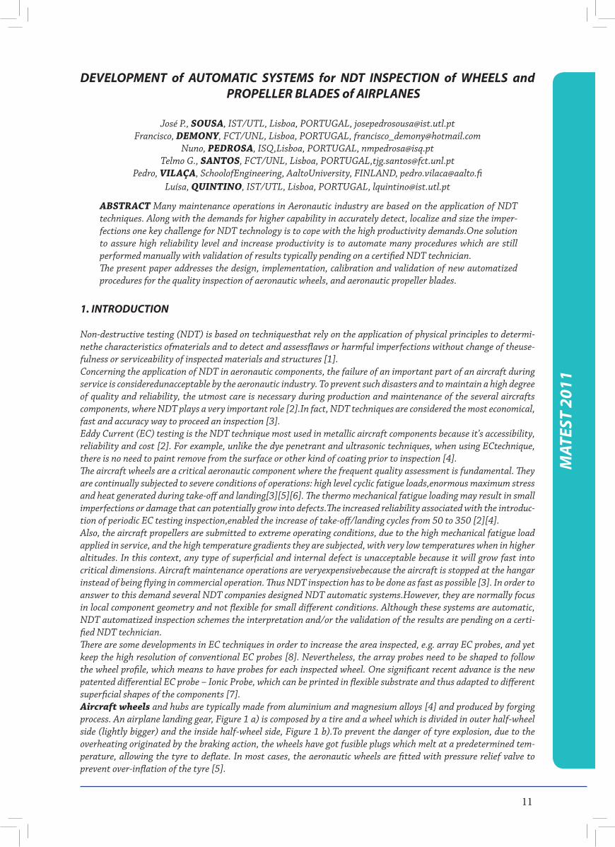
ABSTRACT Many maintenance operations in Aeronautic industry are based on the application of NDT techniques. Along with the demands for higher capability in accurately detect, localize and size the imper-fections one key challenge for NDT technology is to cope with the high productivity demands.One solution to assure high reliability level and increase productivity is to automate many procedures which are still performed manually with validation of results typically pending on a certified NDT technician.The present paper addresses the design, implementation, calibration and validation of new automatized procedures for the quality inspection of aeronautic wheels, and aeronautic propeller blades.
1. INTRODUCTION
Non-destructive testing (NDT) is based on techniquesthat rely on the application of physical principles to determi-nethe characteristics ofmaterials and to detect and assessflaws or harmful imperfections without change of theuse-fulness or serviceability of inspected materials and structures [1].Concerning the application of NDT in aeronautic components, the failure of an important part of an aircraft during service is consideredunacceptable by the aeronautic industry. To prevent such disasters and to maintain a high degree of quality and reliability, the utmost care is necessary during production and maintenance of the several aircrafts components, where NDT plays a very important role [2].In fact, NDT techniques are considered the most economical, fast and accuracy way to proceed an inspection [3].Eddy Current (EC) testing is the NDT technique most used in metallic aircraft components because it’s accessibility, reliability and cost [2]. For example, unlike the dye penetrant and ultrasonic techniques, when using ECtechnique, there is no need to paint remove from the surface or other kind of coating prior to inspection [4].The aircraft wheels are a critical aeronautic component where the frequent quality assessment is fundamental. They are continually subjected to severe conditions of operations: high level cyclic fatigue loads,enormous maximum stress and heat generated during take-off and landing[3][5][6]. The thermo mechanical fatigue loading may result in small imperfections or damage that can potentially grow into defects.The increased reliability associated with the introduc-tion of periodic EC testing inspection,enabled the increase of take-off/landing cycles from 50 to 350 [2][4].Also, the aircraft propellers are submitted to extreme operating conditions, due to the high mechanical fatigue load applied in service, and the high temperature gradients they are subjected, with very low temperatures when in higher altitudes. In this context, any type of superficial and internal defect is unacceptable because it will grow fast into critical dimensions. Aircraft maintenance operations are veryexpensivebecause the aircraft is stopped at the hangar instead of being flying in commercial operation. Thus NDT inspection has to be done as fast as possible [3]. In order to answer to this demand several NDT companies designed NDT automatic systems.However, they are normally focus in local component geometry and not flexible for small different conditions. Although these systems are automatic, NDT automatized inspection schemes the interpretation and/or the validation of the results are pending on a certi-fied NDT technician.There are some developments in EC techniques in order to increase the area inspected, e.g. array EC probes, and yet keep the high resolution of conventional EC probes [8]. Nevertheless, the array probes need to be shaped to follow the wheel profile, which means to have probes for each inspected wheel. One significant recent advance is the new patented differential EC probe – Ionic Probe, which can be printed in flexible substrate and thus adapted to different superficial shapes of the components [7].Aircraft wheels and hubs are typically made from aluminium and magnesium alloys [4] and produced by forging process. An airplane landing gear, Figure 1 a) is composed by a tire and a wheel which is divided in outer half-wheel side (lightly bigger) and the inside half-wheel side, Figure 1 b).To prevent the danger of tyre explosion, due to the overheating originated by the braking action, the wheels have got fusible plugs which melt at a predetermined tem-perature, allowing the tyre to deflate. In most cases, the aeronautic wheels are fitted with pressure relief valve to prevent over-inflation of the tyre [5].
12
MAT
EST
2011
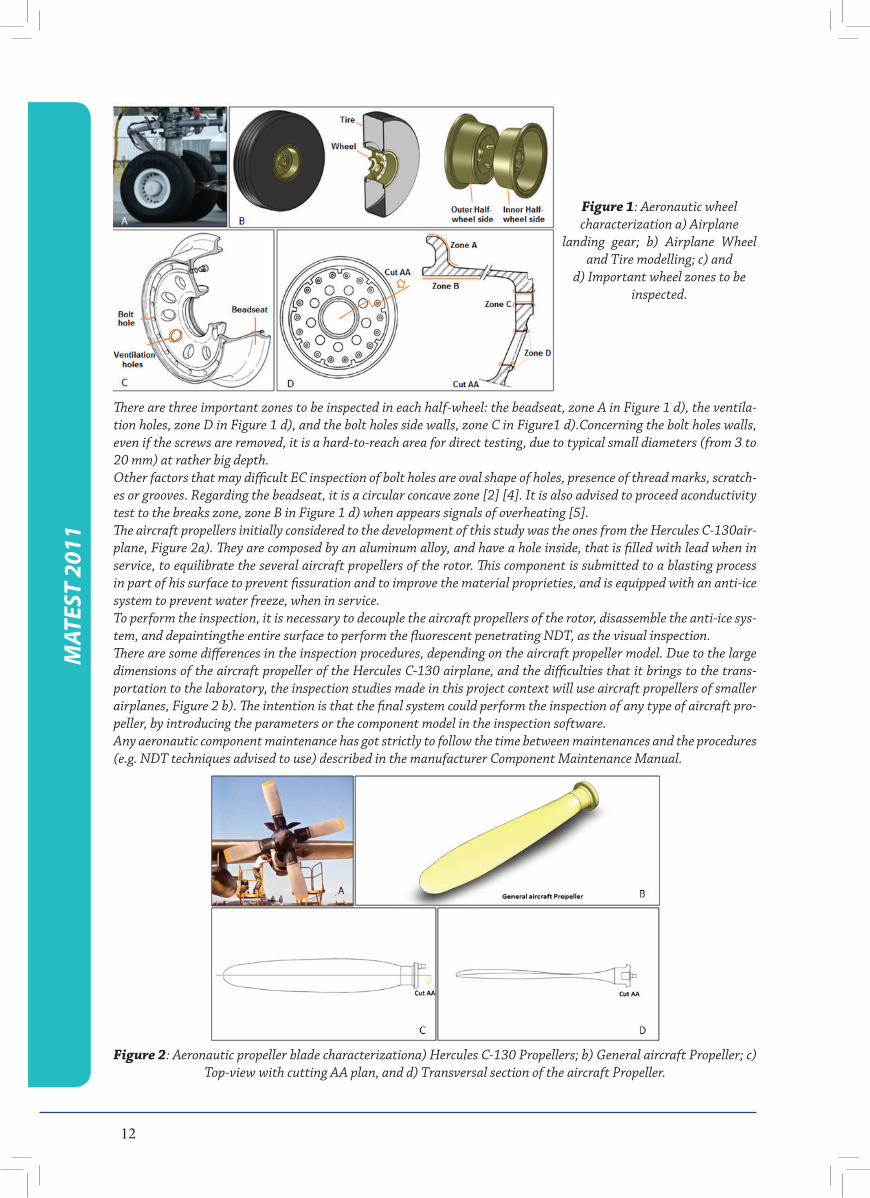
Figure 1: Aeronautic wheel characterization a) Airplane
landing gear; b) Airplane Wheel and Tire modelling; c) and
d) Important wheel zones to be inspected.
There are three important zones to be inspected in each half-wheel: the beadseat, zone A in Figure 1 d), the ventila-tion holes, zone D in Figure 1 d), and the bolt holes side walls, zone C in Figure1 d).Concerning the bolt holes walls, even if the screws are removed, it is a hard-to-reach area for direct testing, due to typical small diameters (from 3 to 20 mm) at rather big depth.Other factors that may difficult EC inspection of bolt holes are oval shape of holes, presence of thread marks, scratch-es or grooves. Regarding the beadseat, it is a circular concave zone [2] [4]. It is also advised to proceed aconductivity test to the breaks zone, zone B in Figure 1 d) when appears signals of overheating [5].The aircraft propellers initially considered to the development of this study was the ones from the Hercules C-130air-plane, Figure 2a). They are composed by an aluminum alloy, and have a hole inside, that is filled with lead when in service, to equilibrate the several aircraft propellers of the rotor. This component is submitted to a blasting process in part of his surface to prevent fissuration and to improve the material proprieties, and is equipped with an anti-ice system to prevent water freeze, when in service.To perform the inspection, it is necessary to decouple the aircraft propellers of the rotor, disassemble the anti-ice sys-tem, and depaintingthe entire surface to perform the fluorescent penetrating NDT, as the visual inspection.There are some differences in the inspection procedures, depending on the aircraft propeller model. Due to the large dimensions of the aircraft propeller of the Hercules C-130 airplane, and the difficulties that it brings to the trans-portation to the laboratory, the inspection studies made in this project context will use aircraft propellers of smaller airplanes, Figure 2 b). The intention is that the final system could perform the inspection of any type of aircraft pro-peller, by introducing the parameters or the component model in the inspection software.Any aeronautic component maintenance has got strictly to follow the time between maintenances and the procedures (e.g. NDT techniques advised to use) described in the manufacturer Component Maintenance Manual.
Figure 2: Aeronautic propeller blade characterizationa) Hercules C-130 Propellers; b) General aircraft Propeller; c) Top-view with cutting AA plan, and d) Transversal section of the aircraft Propeller.
13
MAT
EST
2011
In aircraft wheels maintenance, there are two types of inspections: tire replacement inspection and overhaul. The first inspection occurs every time the tire is changed, normally after 300 landings, and it´s advised to make EC testing in the beadseat zone [5]. The overhaul occurs after five times tire replacement inspection, where all wheel is inspected by Eddy Current and Fluorescent Penetrant testing.Although a superficial inspection may be carried out with the wheel installed on the aircraft, the main wheel mainte-nance is made when it is removed to replacement inspection or overhaul [3]. To enable the wheel inspection, the tire must be removed from the wheel after disassembly the two half-wheel sides. It is made a metal-part, non metal-part and bearing cone cleaning following by the NDT and dimensional inspections.Depending on the wheel damage, we can repair parts that are worn, distorted or damage. In any case a part that is cracked can be repaired. The inspection of the aircraft propellers uses the fluorescent penetrating testing in the entire surface and in the con-nection to the rotor, to detect any possible fissure in the material. The component is submitted to an Eddy Current NDT to ensure that there is no possibility of a fissure in the material, superficial or even sub-superficial, creating a redundancy between the two NDT processes applied, increasing the probability of defects detection. The component is also submitted to a visual inspection inside, using an endoscope, allowing to analyse a zoom of this region (difficult access is the principal restriction to apply other NDT).
2. AUTOMATED SYSTEMS DEVELOPMENT
Main motivation for the prototype’sconception and design are theimprovement of NDT inspection speed, resolution, reliability and easy operation. The operator is then free to focus on the probe signals overcoming problems such as lift-off effect due to loss of perpendicularity of the EC probe to the surface,during manual manipulation. Recording the NDT inspection results is one more added feature.Following it is presented a descriptionof the two NDT automated systems developed, for aircraft wheels and propellers inspection.
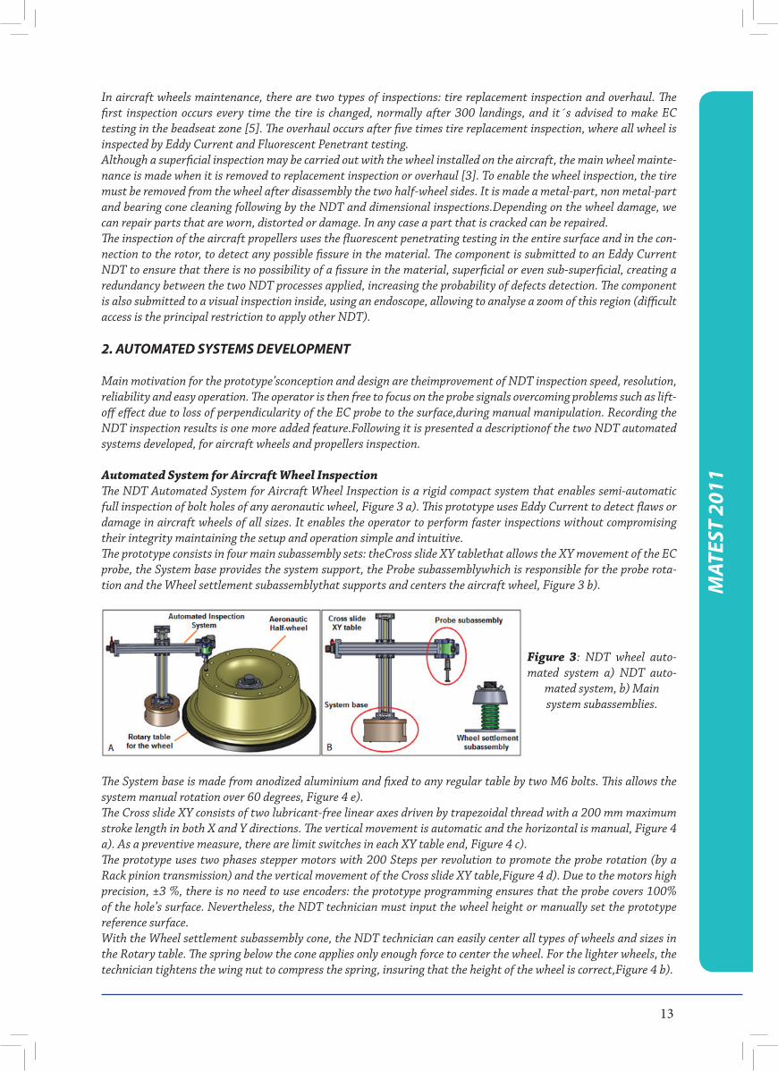
Automated System for Aircraft Wheel InspectionThe NDT Automated System for Aircraft Wheel Inspection is a rigid compact system that enables semi-automatic full inspection of bolt holes of any aeronautic wheel, Figure 3 a). This prototype uses Eddy Current to detect flaws or damage in aircraft wheels of all sizes. It enables the operator to perform faster inspections without compromising their integrity maintaining the setup and operation simple and intuitive. The prototype consists in four main subassembly sets: theCross slide XY tablethat allows the XY movement of the EC probe, the System base provides the system support, the Probe subassemblywhich is responsible for the probe rota-tion and the Wheel settlement subassemblythat supports and centers the aircraft wheel, Figure 3 b).
Figure 3: NDT wheel auto-mated system a) NDT auto-
mated system, b) Main system subassemblies.
The System base is made from anodized aluminium and fixed to any regular table by two M6 bolts. This allows the system manual rotation over 60 degrees, Figure 4 e).The Cross slide XY consists of two lubricant-free linear axes driven by trapezoidal thread with a 200 mm maximum stroke length in both X and Y directions. The vertical movement is automatic and the horizontal is manual, Figure 4 a). As a preventive measure, there are limit switches in each XY table end, Figure 4 c).The prototype uses two phases stepper motors with 200 Steps per revolution to promote the probe rotation (by a Rack pinion transmission) and the vertical movement of the Cross slide XY table,Figure 4 d). Due to the motors high precision, ±3 %, there is no need to use encoders: the prototype programming ensures that the probe covers 100% of the hole’s surface. Nevertheless, the NDT technician must input the wheel height or manually set the prototype reference surface.With the Wheel settlement subassembly cone, the NDT technician can easily center all types of wheels and sizes in the Rotary table. The spring below the cone applies only enough force to center the wheel. For the lighter wheels, the technician tightens the wing nut to compress the spring, insuring that the height of the wheel is correct,Figure 4 b).
14
MAT
EST
2011
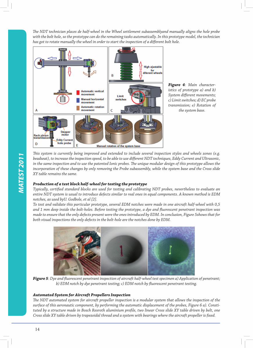
The NDT technician places de half-wheel in the Wheel settlement subassemblyand manually aligns the hole probe with the bolt hole, so the prototype can do the remaining tasks automatically. In this prototype model, the technician has got to rotate manually the wheel in order to start the inspection of a different bolt hole.
Figure 4: Main character-istics of prototype a) and b) System different movements; c) Limit switches; d) EC probe transmission; e) Rotation of
the system base.
This system is currently being improved and extended to include several inspection styles and wheels zones (e.g. beadseat), to increase the inspection speed, to be able to use different NDT techniques, Eddy Current and Ultrasonic, in the same inspection and to use the patented Ionic probes. The unique modular design of this prototype allows the incorporation of these changes by only removing the Probe subassembly, while the system base and the Cross slide XY table remains the same.
Production of a test block half-wheel for testing the prototypeTypically, certified standard blocks are used for testing and calibrating NDT probes, nevertheless to evaluate an entire NDT system is usual to introduce defects similar to real ones in equal components. A known method is EDM notches, as used byU. Godbole, et al [2].To test and validate this particular prototype, several EDM notches were made in one aircraft half-wheel with 0,5 and 1 mm deep inside the bolt-holes. Before testing the prototype, a dye and fluorescent penetrant inspection was made to ensure that the only defects present were the ones introduced by EDM. In conclusion, Figure 5shows that for both visual inspections the only defects in the bolt-hole are the notches done by EDM.
Figure 5: Dye and fluorescent penetrant inspection of aircraft half-wheel test specimen a) Application of penetrant; b) EDM notch by dye penetrant testing; c) EDM notch by fluorescent penetrant testing.
Automated System for Aircraft Propellers InspectionThe NDT automated system for aircraft propeller inspection is a modular system that allows the inspection of the surface of this aeronautic component, by performing the automatic displacement of the probes, Figure 6 a). Consti-tuted by a structure made in Bosch Rexroth aluminium profile, two linear Cross slide XY table driven by belt, one Cross slide XY table driven by trapezoidal thread and a system with bearings where the aircraft propeller is fixed.
15
MAT
EST
2011
Figure 6: NDT propeller blades automated systema) System different movements; b) and c) coupling probes and
stepper motors.
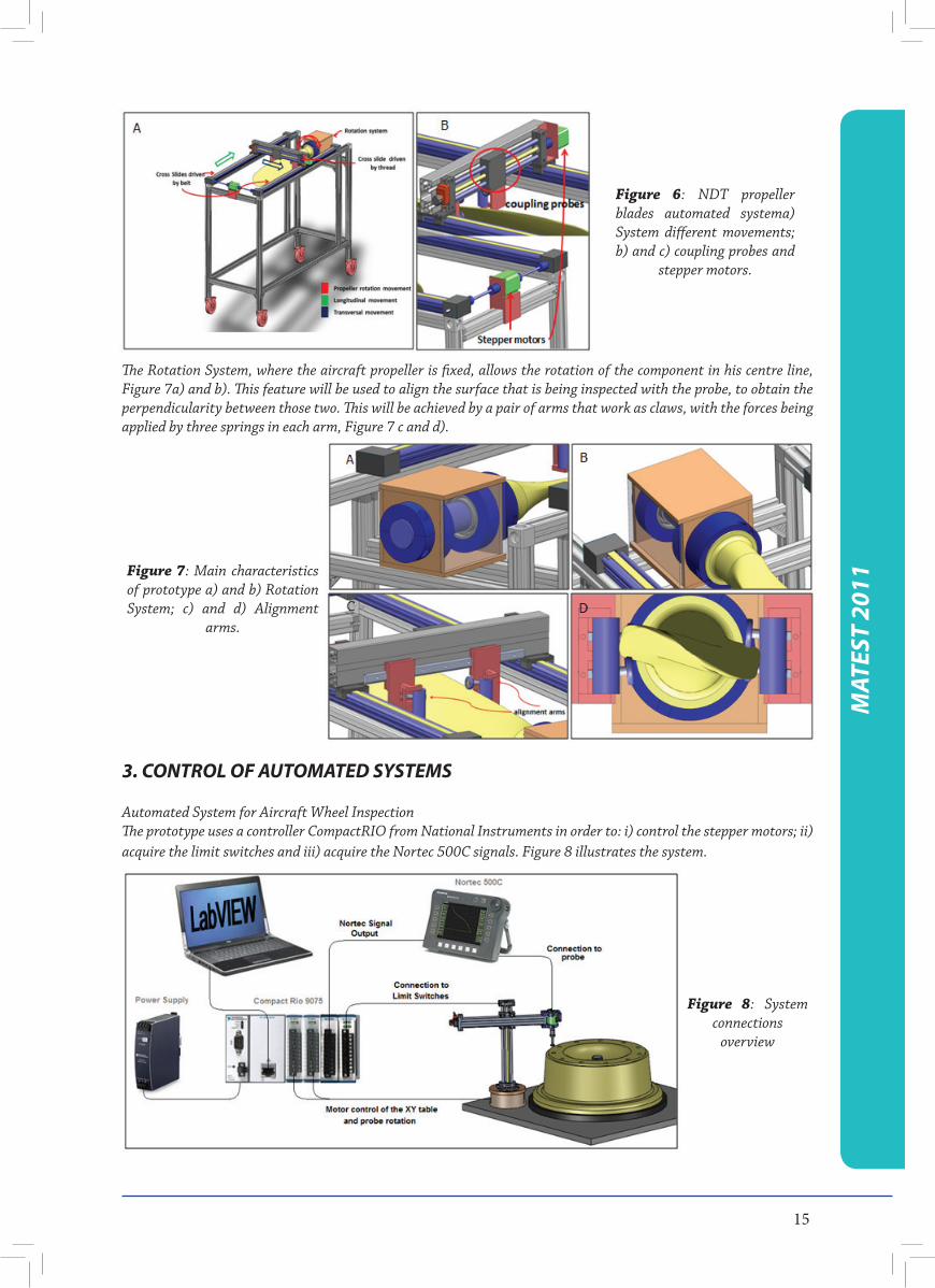
The Rotation System, where the aircraft propeller is fixed, allows the rotation of the component in his centre line, Figure 7a) and b). This feature will be used to align the surface that is being inspected with the probe, to obtain the perpendicularity between those two. This will be achieved by a pair of arms that work as claws, with the forces being applied by three springs in each arm, Figure 7 c and d).
Figure 7: Main characteristics of prototype a) and b) Rotation System; c) and d) Alignment
arms.
3. CONTROL OF AUTOMATED SYSTEMS
Automated System for Aircraft Wheel InspectionThe prototype uses a controller CompactRIO from National Instruments in order to: i) control the stepper motors; ii) acquire the limit switches and iii) acquire the Nortec 500C signals. Figure 8 illustrates the system.
Figure 8: System connections
overview
16
MAT
EST
2011
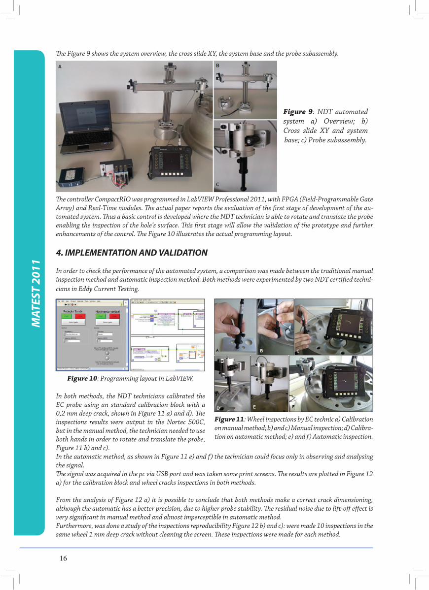
The Figure 9 shows the system overview, the cross slide XY, the system base and the probe subassembly.
Figure 9: NDT automated system a) Overview; b) Cross slide XY and system base; c) Probe subassembly.
The controller CompactRIO was programmed in LabVIEW Professional 2011, with FPGA (Field-Programmable Gate Array) and Real-Time modules. The actual paper reports the evaluation of the first stage of development of the au-tomated system. Thus a basic control is developed where the NDT technician is able to rotate and translate the probe enabling the inspection of the hole’s surface. This first stage will allow the validation of the prototype and further enhancements of the control. The Figure 10 illustrates the actual programming layout.
4. IMPLEMENTATION AND VALIDATION
In order to check the performance of the automated system, a comparison was made between the traditional manual inspection method and automatic inspection method. Both methods were experimented by two NDT certified techni-cians in Eddy Current Testing.
Figure 10: Programming layout in LabVIEW.
Figure 11: Wheel inspections by EC technic a) Calibration on manual method; b) and c) Manual inspection; d) Calibra-tion on automatic method; e) and f) Automatic inspection.
In both methods, the NDT technicians calibrated the EC probe using an standard calibration block with a 0,2 mm deep crack, shown in Figure 11 a) and d). The inspections results were output in the Nortec 500C, but in the manual method, the technician needed to use both hands in order to rotate and translate the probe, Figure 11 b) and c). In the automatic method, as shown in Figure 11 e) and f) the technician could focus only in observing and analysing the signal. The signal was acquired in the pc via USB port and was taken some print screens. The results are plotted in Figure 12 a) for the calibration block and wheel cracks inspections in both methods.
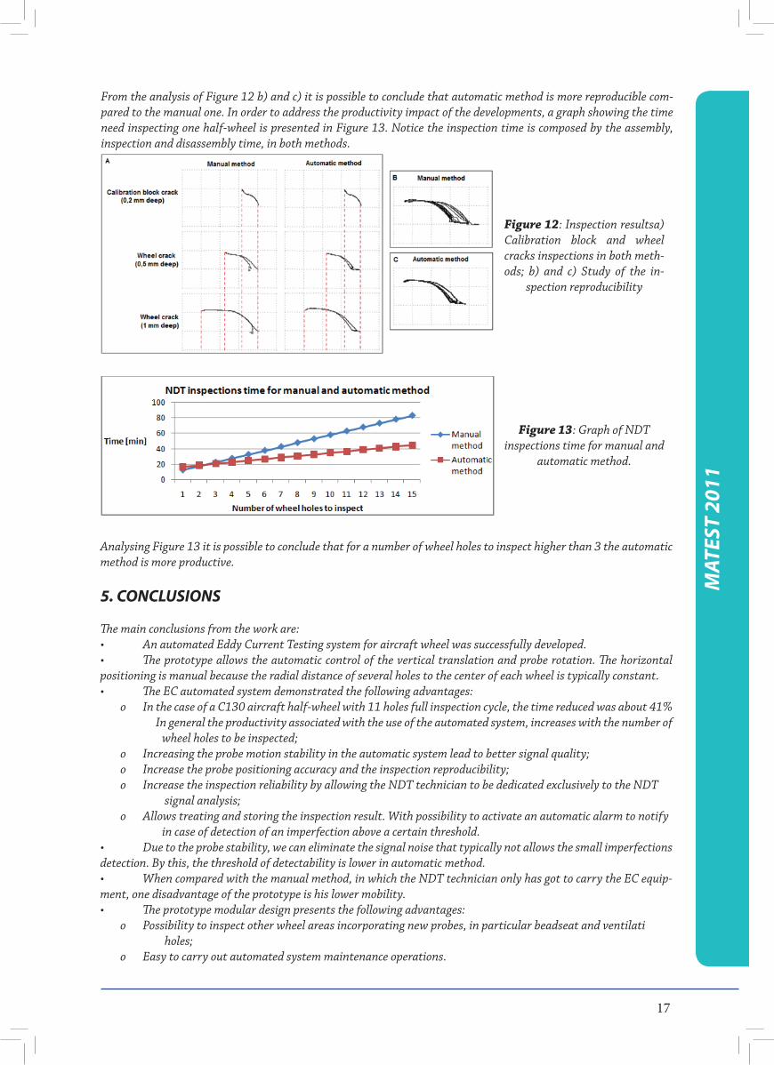
From the analysis of Figure 12 a) it is possible to conclude that both methods make a correct crack dimensioning, although the automatic has a better precision, due to higher probe stability. The residual noise due to lift-off effect is very significant in manual method and almost imperceptible in automatic method.Furthermore, was done a study of the inspections reproducibility Figure 12 b) and c): were made 10 inspections in the same wheel 1 mm deep crack without cleaning the screen. These inspections were made for each method.
17
From the analysis of Figure 12 b) and c) it is possible to conclude that automatic method is more reproducible com-pared to the manual one. In order to address the productivity impact of the developments, a graph showing the time need inspecting one half-wheel is presented in Figure 13. Notice the inspection time is composed by the assembly, inspection and disassembly time, in both methods.
Analysing Figure 13 it is possible to conclude that for a number of wheel holes to inspect higher than 3 the automatic method is more productive.
5. CONCLUSIONS
The main conclusions from the work are:• AnautomatedEddyCurrentTestingsystemforaircraftwheelwassuccessfullydeveloped.• Theprototypeallowstheautomaticcontroloftheverticaltranslationandproberotation.Thehorizontalpositioning is manual because the radial distance of several holes to the center of each wheel is typically constant.• TheECautomatedsystemdemonstratedthefollowingadvantages:
o In the case of a C130 aircraft half-wheel with 11 holes full inspection cycle, the time reduced was about 41% In general the productivity associated with the use of the automated system, increases with the number of wheel holes to be inspected;o Increasing the probe motion stability in the automatic system lead to better signal quality;o Increase the probe positioning accuracy and the inspection reproducibility;o Increase the inspection reliability by allowing the NDT technician to be dedicated exclusively to the NDT signal analysis;o Allows treating and storing the inspection result. With possibility to activate an automatic alarm to notify in case of detection of an imperfection above a certain threshold.
• Duetotheprobestability,wecaneliminatethesignalnoisethattypicallynotallowsthesmallimperfectionsdetection. By this, the threshold of detectability is lower in automatic method.• Whencomparedwiththemanualmethod,inwhichtheNDTtechnicianonlyhasgottocarrytheECequip-ment, one disadvantage of the prototype is his lower mobility.• Theprototypemodulardesignpresentsthefollowingadvantages:
o Possibility to inspect other wheel areas incorporating new probes, in particular beadseat and ventilati holes;o Easy to carry out automated system maintenance operations.
Figure 12: Inspection resultsa) Calibration block and wheel cracks inspections in both meth-ods; b) and c) Study of the in-
spection reproducibility
Figure 13: Graph of NDT inspections time for manual and
automatic method.
MAT
EST
2011
18
MAT
EST
2011
6. REFERENCES
1. T. G. Santos, P. Vilaça, R. M. Miranda, “Electrical conductivity fi eld analysis for evaluation of FSW joints in AA6013 and AA7075 alloys”. Journal of Materials Processing Technology. Volume 211, Issue 2, Pages 174-180. doi:10.1016/j.jmatprotec.2010.08.030. February 2011.2. GODBOLE, U., GOKHALE, A.; Eddy Current Inspection in Aircraft Industry; Proc. National Seminar on Non-Destructive Evaluation; 7 – 9 Dezembro 2006, Hyderabad; http://www.ndt.net/article/nde-india2006/fi les/tp-59-pap.pdf.3. KHAN, Md. AlahiUddin;Non-destructive Testing Applications in Commercial Aircraft Maintenance; 7th European Conference on Non-destructive Testing – ECNDT; 26-29 May 1998, Copenhaga; http://www.ndt.net/article/ecndt98/aero/031/031.htm.4. TurnKey NDT; VD3-71 universal eddy current fl aw detector application for fi eld inspection of aeronautical engineering;http://www.ndt.com.ua/en/articles/2_tools.html.5. CIVIL AVIATION AUTHORITY, U.K.; Civil Aircraft Inspection Procedure, Systems And Equipment – Wheels and Brakes – Chapter AL/3-19, 1973.6. KRAUSE, H.;HOHMANN, R.;GRüNEKLEE, M.; MAUS, M.; ZHANG, Y.; LOMPARSKI, D.; SOLTNER, H.; WOLF, W.; BANZET, M.; SCHUBERT, J.; ZANDER, W.; BOUSACK, H.; BRAGINSKI,A.I.;Aircraft Wheel and Fuse-lage Testing with Eddy Current and SQUID; 7th European Conference on Non-destructive Testing – ECNDT; 26-29 May 1998, Copenhaga; http://www.ndt.net/article/ecndt98/aero/043/043.htm.7. Luís Rosado, Telmo G. Santos, MoisésPiedade, Pedro Ramos, Pedro Vilaça, “Advanced technique for non-destructive testing of friction stir welding of metals”, Measurement (ISSN: 0263-2241), Volume 43, Issue 8, Pages 1021-1030. doi:10.1016/j.measurement.2010.02.006. 2010.8. LECLERC, Rémi, SAMSON, Rock; Eddy Current Array Probes for Aircraft Applications; 15th World Con-ference on Non-Destructive Testing; 15-21 October 2000, Rome;http://www.ndt.net/article/wcndt00/papers/idn514/idn514.htm.
AUTHORS wish to acknowledge to QREN - ADI via project “Aeroinspect”; contract n. 11518, co-supported by FEDER.
19
Za Srpsko društvo za ispitivanje bez razaranja SDIBRGoran Sofronić, dipl. ing.
Poštovani, molim Vas predstavite se našim čitateljima.
Kolega, Davor Gruber i ja, Goran Sofronić dolazimo iz Zavoda za zavarivanje AD - Beograd, firmi koju su osnovali ondašnji vizionari zavarivanja, još davne 1958. godine. Davor je diplomirani inženjer zaštite na radu, operater nivoa 3 (za UT i VT) i neko ko iza sebe ima veoma veliko iskustvo u IBR-u, kako na domaćem tako i na inostranom polju. Ono u čemu je lider u našoj firmi je svakako ultrazvučno ispiti-vanje zbog čega je imenovan za ocenjivača u našem sertifikacionom telu, Zavod CertPers-u. Takođe je i neko ko sve novine u ultrazvučnom ispitivanju im-plementira u našoj firmi. Naš je predstavnik u Insti-tutu za standardizaciju Srbije i član Srpskog društva za ispitivanje bez razaranja (SDIBR).
Ja sam diplomirani inženjer elektrotehnike i tre-nutno obavljam funkciju generalnog direktora Za-voda u kome sam prošao put od pripravnika, preko rukovodioca IBR-a i direktora laboratorije. Dodatna školovanja su svakako bila u oblasti zavarivanja (ev-ropski inženjer zavarivanja-EWE, međunarodni ins-pektor zavarivanja-IWI, operater nivoa 3 za MT i PT) i kvaliteta (vodeći ocenjivač u TUV SUD za ISO 9001 posle završene TUV-ove akademije). Podpredsednik sam SDIBR-a i dugogodičnji član upravnog odbora.
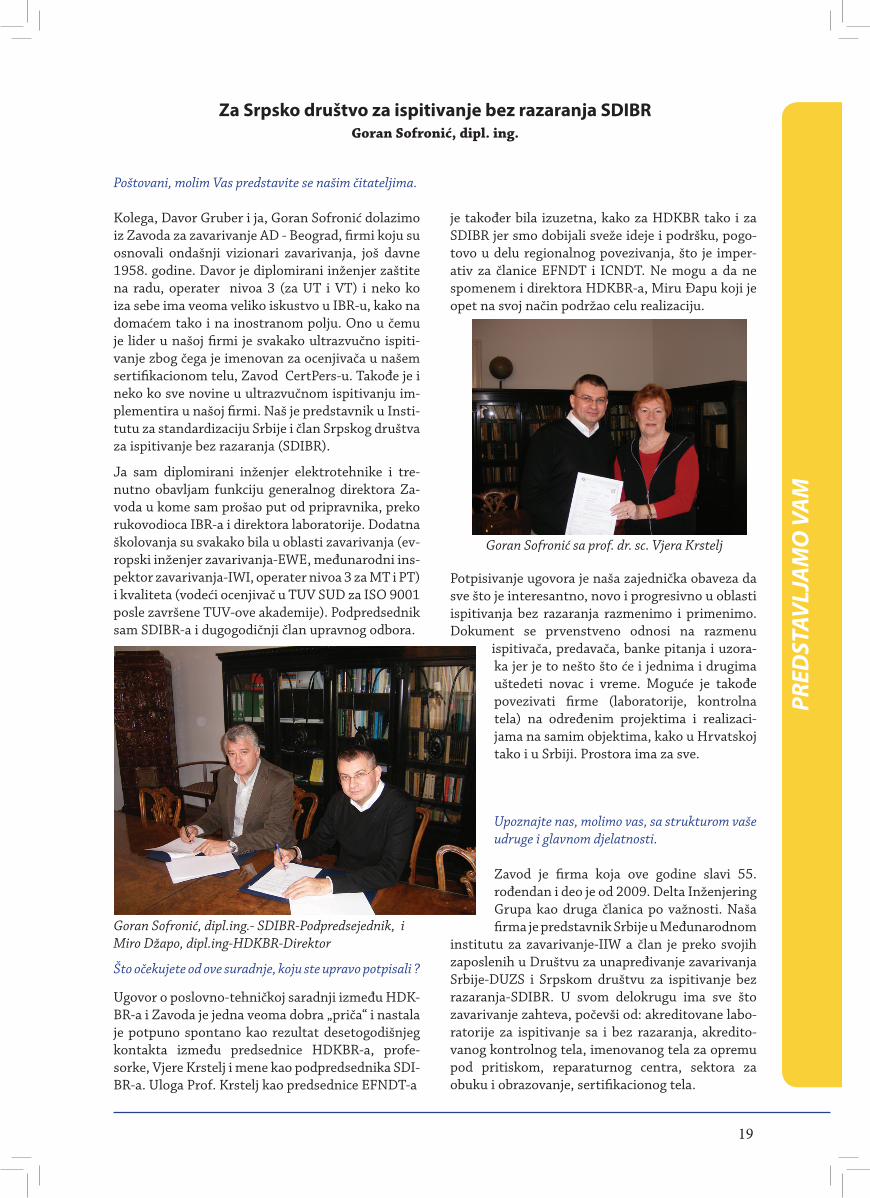
Goran Sofronić, dipl.ing.- SDIBR-Podpredsejednik, i Miro Džapo, dipl.ing-HDKBR-Direktor
Što očekujete od ove suradnje, koju ste upravo potpisali ?
Ugovor o poslovno-tehničkoj saradnji između HDK-BR-a i Zavoda je jedna veoma dobra „priča“ i nastala je potpuno spontano kao rezultat desetogodišnjeg kontakta između predsednice HDKBR-a, profe-sorke, Vjere Krstelj i mene kao podpredsednika SDI-BR-a. Uloga Prof. Krstelj kao predsednice EFNDT-a
je također bila izuzetna, kako za HDKBR tako i za SDIBR jer smo dobijali sveže ideje i podršku, pogo-tovo u delu regionalnog povezivanja, što je imper-ativ za članice EFNDT i ICNDT. Ne mogu a da ne spomenem i direktora HDKBR-a, Miru Đapu koji je opet na svoj način podržao celu realizaciju.
Potpisivanje ugovora je naša zajednička obaveza da sve što je interesantno, novo i progresivno u oblasti ispitivanja bez razaranja razmenimo i primenimo. Dokument se prvenstveno odnosi na razmenu
ispitivača, predavača, banke pitanja i uzora-ka jer je to nešto što će i jednima i drugima uštedeti novac i vreme. Moguće je takođe povezivati firme (laboratorije, kontrolna tela) na određenim projektima i realizaci-jama na samim objektima, kako u Hrvatskoj tako i u Srbiji. Prostora ima za sve.
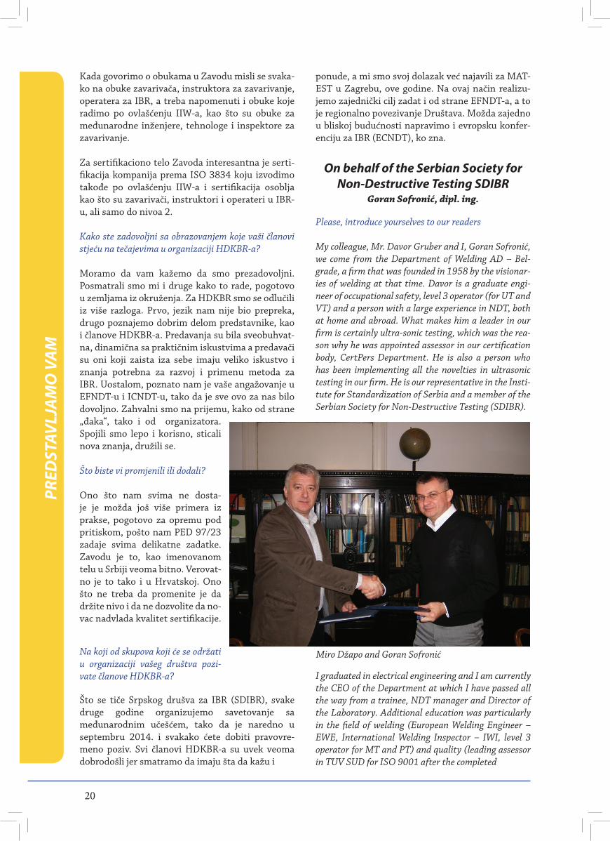
Goran Sofronić sa prof. dr. sc. Vjera Krstelj
Upoznajte nas, molimo vas, sa strukturom vaše udruge i glavnom djelatnosti.
Zavod je firma koja ove godine slavi 55. rođendan i deo je od 2009. Delta Inženjering Grupa kao druga članica po važnosti. Naša firma je predstavnik Srbije u Međunarodnom
institutu za zavarivanje-IIW a član je preko svojih zaposlenih u Društvu za unapređivanje zavarivanja Srbije-DUZS i Srpskom društvu za ispitivanje bez razaranja-SDIBR. U svom delokrugu ima sve što zavarivanje zahteva, počevši od: akreditovane labo-ratorije za ispitivanje sa i bez razaranja, akredito-vanog kontrolnog tela, imenovanog tela za opremu pod pritiskom, reparaturnog centra, sektora za obuku i obrazovanje, sertifikacionog tela.
PRED
STAV
LJAM
O V
AM
20
Kada govorimo o obukama u Zavodu misli se svaka-ko na obuke zavarivača, instruktora za zavarivanje, operatera za IBR, a treba napomenuti i obuke koje radimo po ovlašćenju IIW-a, kao što su obuke za međunarodne inženjere, tehnologe i inspektore za zavarivanje.
Za sertifikaciono telo Zavoda interesantna je serti-fikacija kompanija prema ISO 3834 koju izvodimo takođe po ovlašćenju IIW-a i sertifikacija osoblja kao što su zavarivači, instruktori i operateri u IBR-u, ali samo do nivoa 2.
Kako ste zadovoljni sa obrazovanjem koje vaši članovi stjeću na tečajevima u organizaciji HDKBR-a?
Moramo da vam kažemo da smo prezadovoljni. Posmatrali smo mi i druge kako to rade, pogotovo u zemljama iz okruženja. Za HDKBR smo se odlučili iz više razloga. Prvo, jezik nam nije bio prepreka, drugo poznajemo dobrim delom predstavnike, kao i članove HDKBR-a. Predavanja su bila sveobuhvat-na, dinamična sa praktičnim iskustvima a predavači su oni koji zaista iza sebe imaju veliko iskustvo i znanja potrebna za razvoj i primenu metoda za IBR. Uostalom, poznato nam je vaše angažovanje u EFNDT-u i ICNDT-u, tako da je sve ovo za nas bilo dovoljno. Zahvalni smo na prijemu, kako od strane „đaka“, tako i od organizatora. Spojili smo lepo i korisno, sticali nova znanja, družili se.
Što biste vi promjenili ili dodali?
Ono što nam svima ne dosta-je je možda još više primera iz prakse, pogotovo za opremu pod pritiskom, pošto nam PED 97/23 zadaje svima delikatne zadatke. Zavodu je to, kao imenovanom telu u Srbiji veoma bitno. Verovat-no je to tako i u Hrvatskoj. Ono što ne treba da promenite je da držite nivo i da ne dozvolite da no-vac nadvlada kvalitet sertifikacije.
Na koji od skupova koji će se održati u organizaciji vašeg društva pozi-vate članove HDKBR-a?
Što se tiče Srpskog drušva za IBR (SDIBR), svake druge godine organizujemo savetovanje sa međunarodnim učešćem, tako da je naredno u septembru 2014. i svakako ćete dobiti pravovre-meno poziv. Svi članovi HDKBR-a su uvek veoma dobrodošli jer smatramo da imaju šta da kažu i
ponude, a mi smo svoj dolazak već najavili za MAT-EST u Zagrebu, ove godine. Na ovaj način realizu-jemo zajednički cilj zadat i od strane EFNDT-a, a to je regionalno povezivanje Društava. Možda zajedno u bliskoj budućnosti napravimo i evropsku konfer-enciju za IBR (ECNDT), ko zna.
On behalf of the Serbian Society for Non-Destructive Testing SDIBR
Goran Sofronić, dipl. ing.
Please, introduce yourselves to our readers My colleague, Mr. Davor Gruber and I, Goran Sofronić, we come from the Department of Welding AD – Bel-grade, a firm that was founded in 1958 by the visionar-ies of welding at that time. Davor is a graduate engi-neer of occupational safety, level 3 operator (for UT and VT) and a person with a large experience in NDT, both at home and abroad. What makes him a leader in our firm is certainly ultra-sonic testing, which was the rea-son why he was appointed assessor in our certification body, CertPers Department. He is also a person who has been implementing all the novelties in ultrasonic testing in our firm. He is our representative in the Insti-tute for Standardization of Serbia and a member of the Serbian Society for Non-Destructive Testing (SDIBR).
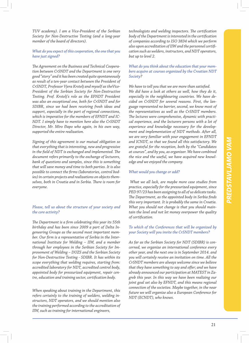
Miro Džapo and Goran Sofronić
PRED
STAV
LJAM
O V
AM
I graduated in electrical engineering and I am currently the CEO of the Department at which I have passed all the way from a trainee, NDT manager and Director of the Laboratory. Additional education was particularly in the field of welding (European Welding Engineer – EWE, International Welding Inspector – IWI, level 3 operator for MT and PT) and quality (leading assessor in TUV SUD for ISO 9001 after the completed
21
TUV academy). I am a Vice-President of the Serbian Society for Non-Destructive Testing (and a long-year member of the board of directors).
What do you expect of this cooperation, the one that you have just signed?
The Agreement on the Business and Technical Coopera-tion between CrSNDT and the Department is one very good “story” and it has been created quite spontaneously as result of a ten-year contact between the President of CrSNDT, Professor Vjera Krstelj and myself as theVice-President of the Serbian Society for Non-Destructive Testing. Prof. Krstelj’s role as the EFNDT President was also an exceptional one, both for CrSNDT and for SDIBR, since we had been receiving fresh ideas and support, especially in the part of regional connections, which is imperative for the members of EFNDT and IC-NDT. I simply have to mention here also the CrSNDT Director, Mr. Miro Đapo who again, in his own way, supported the entire realization.
Signing of this agreement is our mutual obligation so that everything that is interesting, new and progressive in the field of NDT is exchanged and implemented. The document refers primarily to the exchange of lecturers, bank of questions and samples, since this is something that will save money and time to both parties. It is also possible to connect the firms (laboratories, control bod-ies) in certain projects and realizations on objects them-selves, both in Croatia and in Serbia. There is room for everyone.
Please, tell us about the structure of your society and the core activity?
The Department is a firm celebrating this year its 55th birthday and has been since 2009 a part of Delta In-geneering Groups as the second most important mem-ber. Our firm is a representative of Serbia in the Inter-national Institute for Welding – IIW, and a member through her employees in the Serbian Society for Im-provement of Welding – DUZS and the Serbian Society for Non-Destructive Testing - SDIBR. It has within its scope everything that welding requires, starting from: accredited laboratory for NDT, accredited control body, appointed body for pressurized equipment, repair cen-tre, education and training sector, certification body.
When speaking about training in the Department, this refers certainly to the training of welders, welding in-structors, NDT operators, and we should mention also the training performed according to the accreditation of IIW, such as training for international engineers,
technologists and welding inspectors. The certification body of the Department is interested in the certification of companies according to ISO 3834 which we perform also upon accreditation of IIW and the personnel certifi-cation such as welders, instructors, and NDT operators, but up to level 2.
What do you think about the education that your mem-bers acquire at courses organized by the Croatian NDT Society?
We have to tell you that we are more than satisfied. We did have a look at others as well, how they do it, especially in the neighbouring countries. We have de-cided on CrSNDT for several reasons. First, the lan-guage represented no barrier, second, we know most of the representatives as well as the CrSNDT members. The lectures were comprehensive, dynamic with practi-cal experience, and the lecturers persons with a lot of experience and knowledge necessary for the develop-ment and implementation of NDT methods. After all, we are very familiar with your engagement in EFNDT and ICNDT, so that we found all this satisfactory. We are grateful for the reception, both by the “Candidates at cources”, and by you, as organizer. We have combined the nice and the useful, we have acquired new knowl-edge and we enjoyed the company.
What would you change or add?
What we all lack, are maybe more case studies from practice, especially for the pressurized equipment, since PED 97/23 has been assigning to all of us delicate tasks. The Department, as the appointed body in Serbia finds this very important. It is probably the same in Croatia. What you should not change is that you should main-tain the level and not let money overpower the quality of certification.
To which of the Conferences that will be organized by your Society will you invite the CrSNDT members? As far as the Serbian Society for NDT (SDIBR) is con-cerned, we organize an international conference every other year, and the next one is in September 2014. and you will certainly receive an invitation on time. All the CrSNDT members are always welcome since we believe that they have something to say and offer; and we have already announced our participation at MATEST in Za-greb this year. In this way we have been realizing our joint goal set also by EFNDT, and this means regional connection of the societies. Maybe together, in the near future we will organize also a European Conference for NDT (ECNDT), who knows.
PRED
STAV
LJAM
O V
AM
22
Preventive maintenance: Function and added value of preventive thermographic measurements in the framework of industrial maintenance
Siegfried Vogelbacher TESTO; Senior Manager
Testo AG, headquartered in Lenzkirch in South-West Germany, is a world leader in the manufacture of portable and stationary measurement technology. About 2400 employees in 31 international subsidiaries research, develop, produce and market for Testo with one aim: to create innovative measurement solutions, e. g. for the sectors climate, health, food, building technology and emission control. In 2012 Testo achieved a turnover of 221 Million Euro. Roughly 10 percent of the annual turnover is invested in Research & De-velopment
A core expertise of Testo AG is the development and production of thermal imagers. The company offers a broad spectrum of high-quality instruments “Made in Germany”, whose resolutions ranging from 160 x 120 pixels via 320 x 240 pixels to 640 x 480 pixels fulfil all demands. With the SuperResolution technology, the infrared im-age quality of all Testo thermal imagers can even be im-proved by one class at the touch of a button. Four times more measurement values and a geometric resolution of the infrared image improved by a factor of 1.6 mean for the customer even higher-resolution thermal images and even more security in the measurement.
In maintenance work, the high-resolution testo 885 not only allows dangerous fire risks to be minimized and production downtimes to be avoided. Using the patent-pending SiteRecognition technology, extremely efficient inspection route management for mechanical and electrical applications is also possible.
If machines fail or if production has to be interrupted because of defective components in a system, this has far-reaching financial consequences for a company, be-cause unexpected downtimes cause a drop in the pro-ductivity and profitability of the company. If overload or other damage causes a fire, then the staff in a produc-tion site are also placed in danger. For these reasons, preventive maintenance and the regular servicing of machines are of central significance in industrial main-tenance. Reliable and fast servicing methods are indis-pensible with regard to this.
Thermography provides an economically attractive method of maintenance. Damaged or endangered elec-trical and mechanical components can be diagnosed by their thermal properties. If a conductor, a cable or a fuse is defective, or if individual components fail, an increased resistance is created, causing an atypical heat development. Friction, incorrect adjustment, play in the components or lack of symmetry also lead to an
increased heat development. Conspicuous changes in the thermal quality of individual components function as indicators for potential or actual defects. Not only existing faults, but also potential sources of error and danger can be directly and accurately diagnosed using thermography. This way, potential sources of error can be diagnosed before failures or fires can occur. Finally, thermographic images provide a reliable, visual possi-bility for the documentation of faults, as well as a long-term timeline comparison of the status of a system.
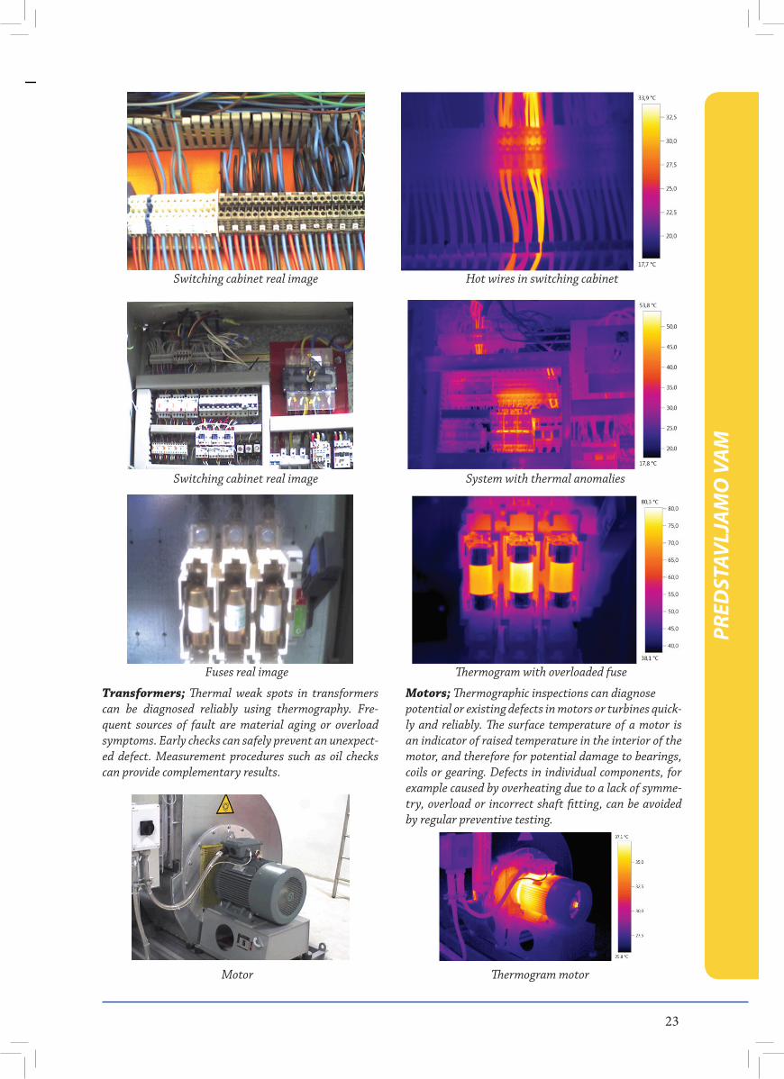
Thermographic measurement methods are used in many different areas of application. In electrical sys-tems, infrared measurements are possible at all voltage levels. For example, switch boxes, distributors, cables and wires, fuses, motors and other components in low voltage systems can be tested using the thermographic measurement procedure, but also means of production in medium, high or highest voltage systems (outdoor switchgear). The diagnosis of defective wiring or fuses, loose screw or clamp connections, overloaded switches or defective insulation in a switching cabinet is directly and accurately possible.
Electrical switchgear
Overloaded condensers, overheated wires or circuit breakers, loose clamps, damaged insulation or defec-tive screw connections are only a few of the components which can lead to damage or failure of a system. Faults on individual components are sufficient to risk failure or fire in the entire system. Roughly 35 percent of all fires in industrial businesses can be traced to extreme overheating in electrical components.1 Thermographic inspections ensure fast and precise maintenance of a system, preventing the danger of failure or fire. The sec-ond thermographic inspection of a system already low-ers the risk of failure by about 80 percent.2
1 Instandhaltung (06/2007): Der Kampf mit den Hot Spots. S. 41.2 Instandhaltung (06/2007): Der Kampf mit den Hot Spots. S. 41.
PRED
STAV
LJAM
O V
AM
23
Switching cabinet real image Hot wires in switching cabinet
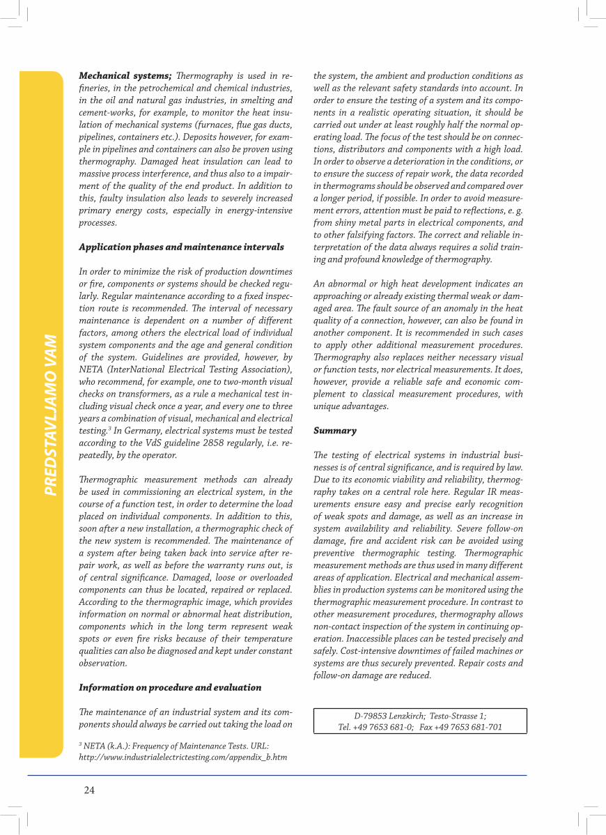
Switching cabinet real image System with thermal anomalies
Fuses real image Thermogram with overloaded fuse
Transformers; Thermal weak spots in transformers can be diagnosed reliably using thermography. Fre-quent sources of fault are material aging or overload symptoms. Early checks can safely prevent an unexpect-ed defect. Measurement procedures such as oil checks can provide complementary results.
Motors; Thermographic inspections can diagnose potential or existing defects in motors or turbines quick-ly and reliably. The surface temperature of a motor is an indicator of raised temperature in the interior of the motor, and therefore for potential damage to bearings, coils or gearing. Defects in individual components, for example caused by overheating due to a lack of symme-try, overload or incorrect shaft fitting, can be avoided by regular preventive testing.
Motor Thermogram motor
PRED
STAV
LJAM
O V
AM
24
Mechanical systems; Thermography is used in re-fineries, in the petrochemical and chemical industries, in the oil and natural gas industries, in smelting and cement-works, for example, to monitor the heat insu-lation of mechanical systems (furnaces, flue gas ducts, pipelines, containers etc.). Deposits however, for exam-ple in pipelines and containers can also be proven using thermography. Damaged heat insulation can lead to massive process interference, and thus also to a impair-ment of the quality of the end product. In addition to this, faulty insulation also leads to severely increased primary energy costs, especially in energy-intensive processes.
Application phases and maintenance intervals
In order to minimize the risk of production downtimes or fire, components or systems should be checked regu-larly. Regular maintenance according to a fixed inspec-tion route is recommended. The interval of necessary maintenance is dependent on a number of different factors, among others the electrical load of individual system components and the age and general condition of the system. Guidelines are provided, however, by NETA (InterNational Electrical Testing Association), who recommend, for example, one to two-month visual checks on transformers, as a rule a mechanical test in-cluding visual check once a year, and every one to three years a combination of visual, mechanical and electrical testing.3 In Germany, electrical systems must be tested according to the VdS guideline 2858 regularly, i.e. re-peatedly, by the operator.
Thermographic measurement methods can already be used in commissioning an electrical system, in the course of a function test, in order to determine the load placed on individual components. In addition to this, soon after a new installation, a thermographic check of the new system is recommended. The maintenance of a system after being taken back into service after re-pair work, as well as before the warranty runs out, is of central significance. Damaged, loose or overloaded components can thus be located, repaired or replaced. According to the thermographic image, which provides information on normal or abnormal heat distribution, components which in the long term represent weak spots or even fire risks because of their temperature qualities can also be diagnosed and kept under constant observation.
Information on procedure and evaluation
The maintenance of an industrial system and its com-ponents should always be carried out taking the load on
the system, the ambient and production conditions as well as the relevant safety standards into account. In order to ensure the testing of a system and its compo-nents in a realistic operating situation, it should be carried out under at least roughly half the normal op-erating load. The focus of the test should be on connec-tions, distributors and components with a high load. In order to observe a deterioration in the conditions, or to ensure the success of repair work, the data recorded in thermograms should be observed and compared over a longer period, if possible. In order to avoid measure-ment errors, attention must be paid to reflections, e. g. from shiny metal parts in electrical components, and to other falsifying factors. The correct and reliable in-terpretation of the data always requires a solid train-ing and profound knowledge of thermography.
An abnormal or high heat development indicates an approaching or already existing thermal weak or dam-aged area. The fault source of an anomaly in the heat quality of a connection, however, can also be found in another component. It is recommended in such cases to apply other additional measurement procedures. Thermography also replaces neither necessary visual or function tests, nor electrical measurements. It does, however, provide a reliable safe and economic com-plement to classical measurement procedures, with unique advantages.
Summary
The testing of electrical systems in industrial busi-nesses is of central significance, and is required by law. Due to its economic viability and reliability, thermog-raphy takes on a central role here. Regular IR meas-urements ensure easy and precise early recognition of weak spots and damage, as well as an increase in system availability and reliability. Severe follow-on damage, fire and accident risk can be avoided using preventive thermographic testing. Thermographic measurement methods are thus used in many different areas of application. Electrical and mechanical assem-blies in production systems can be monitored using the thermographic measurement procedure. In contrast to other measurement procedures, thermography allows non-contact inspection of the system in continuing op-eration. Inaccessible places can be tested precisely and safely. Cost-intensive downtimes of failed machines or systems are thus securely prevented. Repair costs and follow-on damage are reduced.
3 NETA (k.A.): Frequency of Maintenance Tests. URL: http://www.industrialelectrictesting.com/appendix_b.htm
D-79853 Lenzkirch; Testo-Strasse 1;Tel. +49 7653 681-0; Fax +49 7653 681-701
PRED
STAV
LJAM
O V
AM
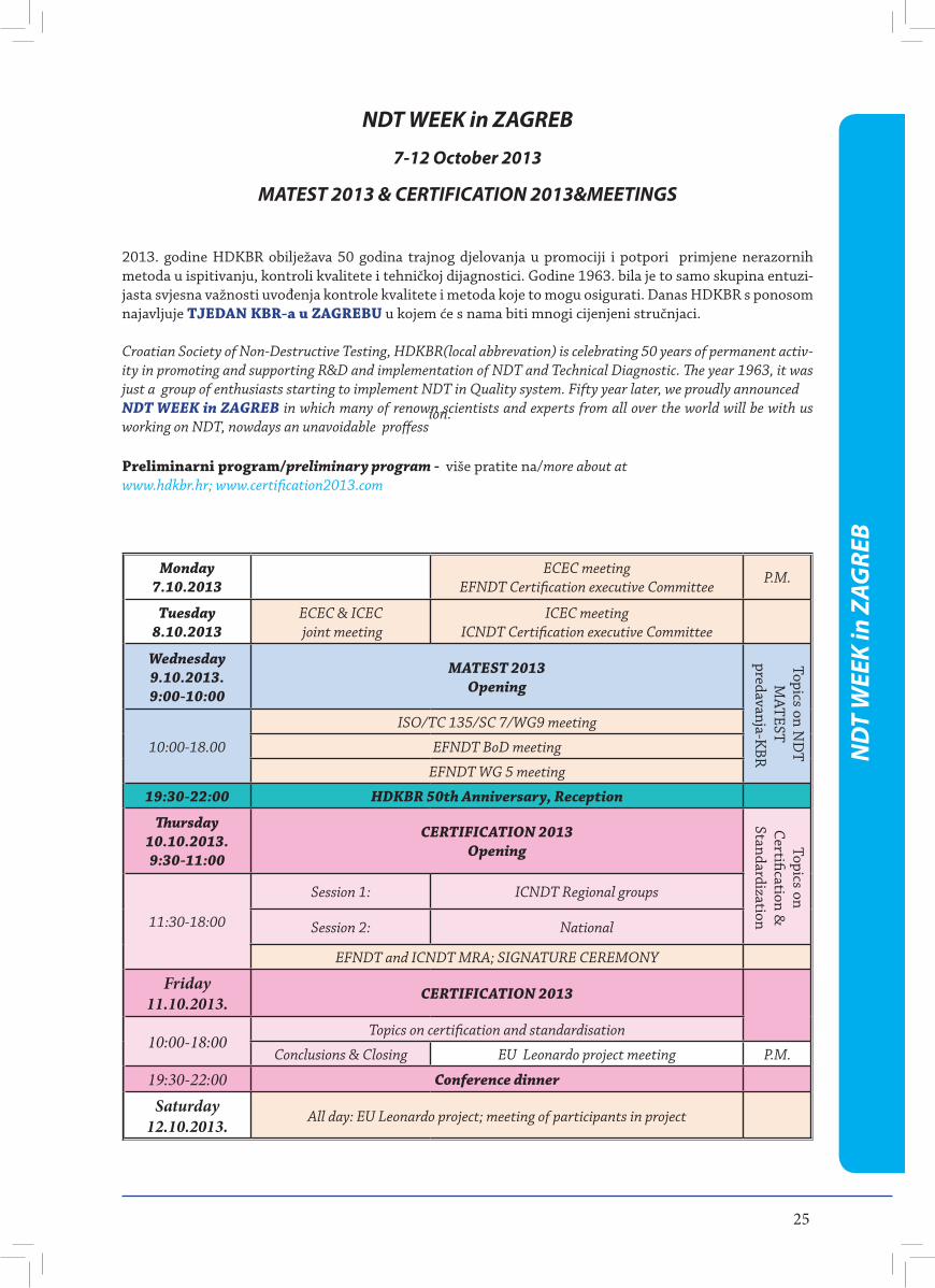
25
NDT WEEK in ZAGREB
7-12 October 2013
MATEST 2013 & CERTIFICATION 2013&MEETINGS
2013. godine HDKBR obilježava 50 godina trajnog djelovanja u promociji i potpori primjene nerazornih metoda u ispitivanju, kontroli kvalitete i tehničkoj dijagnostici. Godine 1963. bila je to samo skupina entuzi-jasta svjesna važnosti uvođenja kontrole kvalitete i metoda koje to mogu osigurati. Danas HDKBR s ponosom najavljuje TJEDAN KBR-a u ZAGREBU u kojem će s nama biti mnogi cijenjeni stručnjaci.
Croatian Society of Non-Destructive Testing, HDKBR(local abbrevation) is celebrating 50 years of permanent activ-ity in promoting and supporting R&D and implementation of NDT and Technical Diagnostic. The year 1963, it was just a group of enthusiasts starting to implement NDT in Quality system. Fifty year later, we proudly announced NDT WEEK in ZAGREB in which many of renown scientists and experts from all over the world will be with us working on NDT, nowdays an unavoidable proffess
ion.
Preliminarni program/preliminary program - više pratite na/more about at www.hdkbr.hr; www.certification2013.com
ND
T W
EEK
in Z
AGRE
B
Monday7.10.2013
ECEC meetingEFNDT Certification executive Committee
P.M.
Tuesday8.10.2013
ECEC & ICEC joint meeting
ICEC meetingICNDT Certification executive Committee
Wednesday9.10.2013.9:00-10:00
MATEST 2013 Opening
10:00-18.00
ISO/TC 135/SC 7/WG9 meeting
EFNDT BoD meeting
EFNDT WG 5 meeting
19:30-22:00 HDKBR 50th Anniversary, Reception
Thursday10.10.2013.9:30-11:00
CERTIFICATION 2013 Opening
11:30-18:00
Session 1: ICNDT Regional groups
Session 2: National
EFNDT and ICNDT MRA; SIGNATURE CEREMONY
Friday11.10.2013. CERTIFICATION 2013
10:00-18:00Topics on certification and standardisation
Conclusions & Closing EU Leonardo project meeting P.M.
19:30-22:00 Conference dinner
Saturday12.10.2013. All day: EU Leonardo project; meeting of participants in project
Topics on ND
TM
ATEST predavanja-K
BR
Topics on Certification &
Standardization
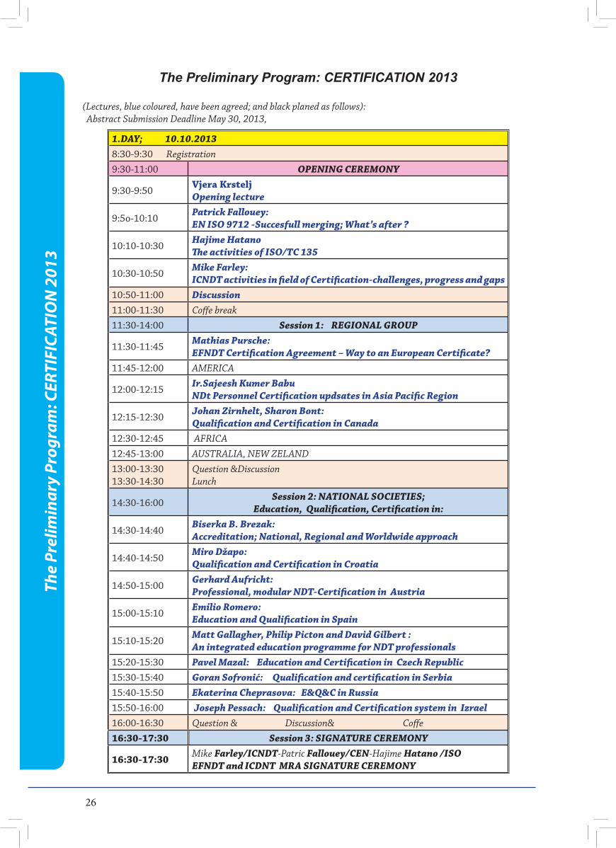
26
1.DAY; 10.10.20138:30-9:30 Registration9:30-11:00 OPENING CEREMONY
9:30-9:50Vjera KrsteljOpening lecture
9:5o-10:10Patrick Fallouey: EN ISO 9712 -Succesfull merging; What’s after ?
10:10-10:30Hajime HatanoThe activities of ISO/TC 135
10:30-10:50Mike Farley:ICNDT activities in field of Certification-challenges, progress and gaps
10:50-11:00 Discussion11:00-11:30 Coffe break11:30-14:00 Session 1: REGIONAL GROUP
11:30-11:45Mathias Pursche:EFNDT Certification Agreement – Way to an European Certificate?
11:45-12:00 AMERICA
12:00-12:15Ir.Sajeesh Kumer BabuNDt Personnel Certification updsates in Asia Pacific Region
12:15-12:30Johan Zirnhelt, Sharon Bont: Qualification and Certification in Canada
12:30-12:45 AFRICA12:45-13:00 AUSTRALIA, NEW ZELAND13:00-13:3013:30-14:30
Question &DiscussionLunch
14:30-16:00Session 2: NATIONAL SOCIETIES;
Education, Qualification, Certification in:
14:30-14:40Biserka B. Brezak:Accreditation; National, Regional and Worldwide approach
14:40-14:50Miro Džapo: Qualification and Certification in Croatia
14:50-15:00Gerhard Aufricht: Professional, modular NDT-Certification in Austria
15:00-15:10Emilio Romero: Education and Qualification in Spain
15:10-15:20Matt Gallagher, Philip Picton and David Gilbert :An integrated education programme for NDT professionals
15:20-15:30 Pavel Mazal: Education and Certification in Czech Republic 15:30-15:40 Goran Sofronić: Qualification and certification in Serbia15:40-15:50 Ekaterina Cheprasova: E&Q&C in Russia15:50-16:00 Joseph Pessach: Qualification and Certification system in Izrael 16:00-16:30 Question & Discussion& Coffe16:30-17:30 Session 3: SIGNATURE CEREMONY
16:30-17:30 Mike Farley/ICNDT-Patric Fallouey/CEN-Hajime Hatano /ISO EFNDT and ICDNT MRA SIGNATURE CEREMONY
The Preliminary Program: CERTIFICATION 2013
(Lectures, blue coloured, have been agreed; and black planed as follows): Abstract Submission Deadline May 30, 2013,
The
Prel
imin
ary
Prog
ram
: CER
TIFI
CATI
ON
201
3
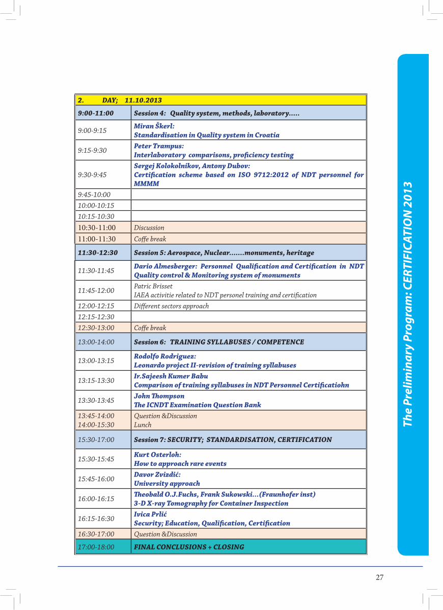
27
2. DAY; 11.10.2013
9:00-11:00 Session 4: Quality system, methods, laboratory.....
9:00-9:15Miran Škerl:Standardisation in Quality system in Croatia
9:15-9:30Peter Trampus:Interlaboratory comparisons, proficiency testing
9:30-9:45Sergej Kolokolnikov, Antony Dubov: Certification scheme based on ISO 9712:2012 of NDT personnel for MMMM
9:45-10:0010:00-10:1510:15-10:30
10:30-11:00 Discussion
11:00-11:30 Coffe break
11:30-12:30 Session 5: Aerospace, Nuclear.......monuments, heritage
11:30-11:45Dario Almesberger: Personnel Qualification and Certification in NDT Quality control & Monitoring system of monuments
11:45-12:00Patric BrissetIAEA activitie related to NDT personel training and certification
12:00-12:15 Different sectors approach12:15-12:3012:30-13:00 Coffe break
13:00-14:00 Session 6: TRAINING SYLLABUSES / COMPETENCE
13:00-13:15Rodolfo Rodriguez:Leonardo project II-revision of training syllabuses
13:15-13:30Ir.Sajeesh Kumer BabuComparison of training syllabuses in NDT Personnel Certificatiohn
13:30-13:45John ThompsonThe ICNDT Examination Question Bank
13:45-14:0014:00-15:30
Question &DiscussionLunch
15:30-17:00 Session 7: SECURITY; STANDARDISATION, CERTIFICATION
15:30-15:45Kurt Osterloh:How to approach rare events
15:45-16:00Davor Zvizdić:University approach
16:00-16:15Theobald O.J.Fuchs, Frank Sukowski...(Fraunhofer inst)3-D X-ray Tomography for Container Inspection
16:15-16:30Ivica PrlićSecurity; Education, Qualification, Certification
16:30-17:00 Question &Discussion
17:00-18:00 FINAL CONCLUSIONS + CLOSING
The
Prel
imin
ary
Prog
ram
: CER
TIFI
CATI
ON
201
3
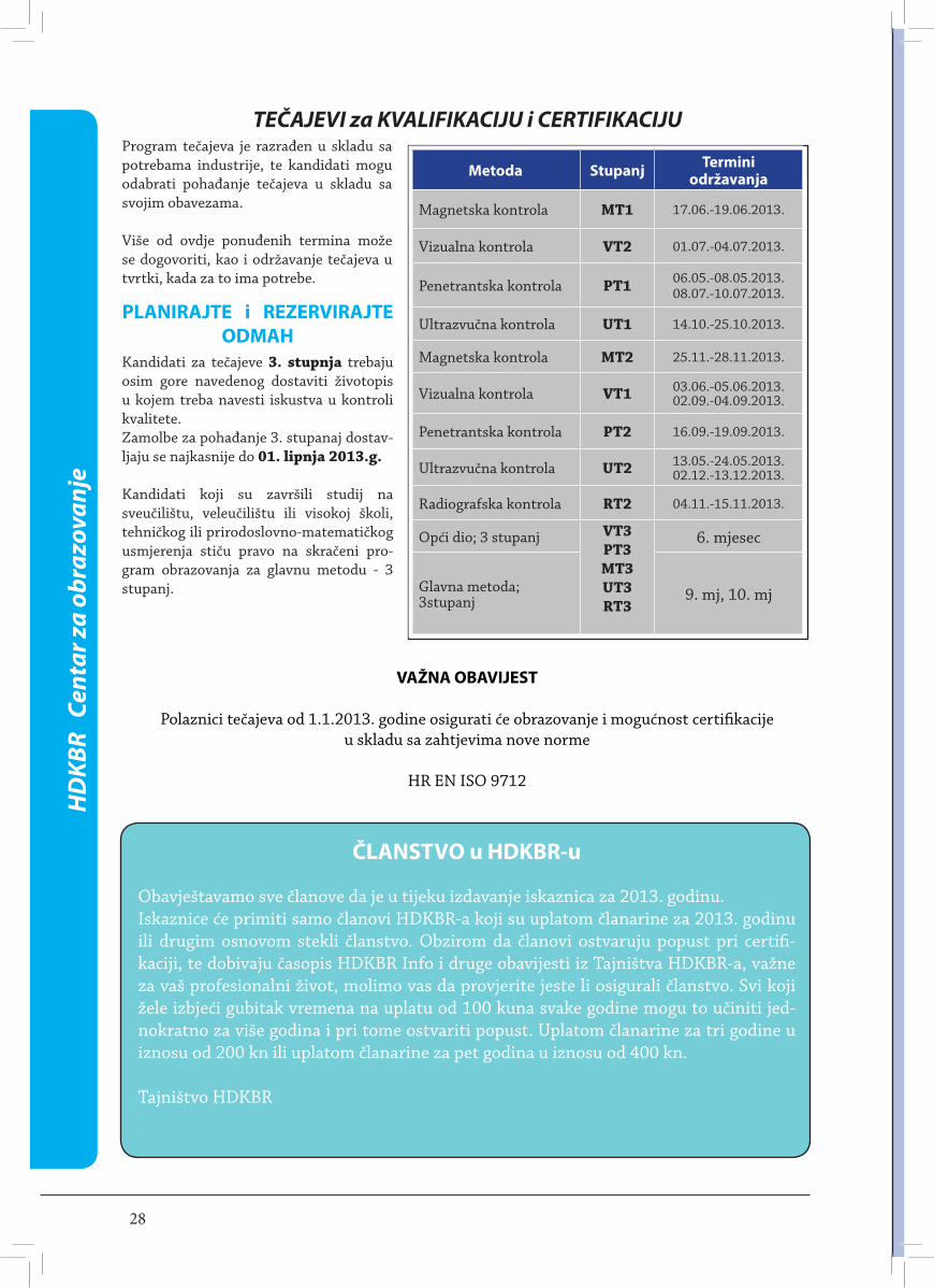
TEČAJEVI za KVALIFIKACIJU i CERTIFIKACIJU
Metoda Stupanj Termini održavanja
Magnetska kontrola MT1 17.06.-19.06.2013.
Vizualna kontrola VT2 01.07.-04.07.2013.
Penetrantska kontrola PT1 06.05.-08.05.2013.08.07.-10.07.2013.
Ultrazvučna kontrola UT1 14.10.-25.10.2013.
Magnetska kontrola MT2 25.11.-28.11.2013.
Vizualna kontrola VT1 03.06.-05.06.2013.02.09.-04.09.2013.
Penetrantska kontrola PT2 16.09.-19.09.2013.
Ultrazvučna kontrola UT2 13.05.-24.05.2013.02.12.-13.12.2013.
Radiografska kontrola RT2 04.11.-15.11.2013.
Opći dio; 3 stupanj VT3PT3MT3UT3RT3
6. mjesec
Glavna metoda; 3stupanj 9. mj, 10. mj
28
HD
KBR
Cen
tar z
a ob
razo
vanj
e
VAŽNA OBAVIJEST
Polaznici tečajeva od 1.1.2013. godine osigurati će obrazovanje i mogućnost certifikacije u skladu sa zahtjevima nove norme
HR EN ISO 9712
Kandidati za tečajeve 3. stupnja trebaju osim gore navedenog dostaviti životopis u kojem treba navesti iskustva u kontroli kvalitete.Zamolbe za pohađanje 3. stupanaj dostav-ljaju se najkasnije do 01. lipnja 2013.g.
Kandidati koji su završili studij na sveučilištu, veleučilištu ili visokoj školi, tehničkog ili prirodoslovno-matematičkog usmjerenja stiču pravo na skračeni pro-gram obrazovanja za glavnu metodu - 3 stupanj.
Program tečajeva je razrađen u skladu sa potrebama industrije, te kandidati mogu odabrati pohađanje tečajeva u skladu sa svojim obavezama.
Više od ovdje ponuđenih termina može se dogovoriti, kao i održavanje tečajeva u tvrtki, kada za to ima potrebe.
PLANIRAJTE i REZERVIRAJTE ODMAH
ČLANSTVO u HDKBR-u
Obavještavamo sve članove da je u tijeku izdavanje iskaznica za 2013. godinu.Iskaznice će primiti samo članovi HDKBR-a koji su uplatom članarine za 2013. godinu ili drugim osnovom stekli članstvo. Obzirom da članovi ostvaruju popust pri certifi-kaciji, te dobivaju časopis HDKBR Info i druge obavijesti iz Tajništva HDKBR-a, važne za vaš profesionalni život, molimo vas da provjerite jeste li osigurali članstvo. Svi koji žele izbjeći gubitak vremena na uplatu od 100 kuna svake godine mogu to učiniti jed-nokratno za više godina i pri tome ostvariti popust. Uplatom članarine za tri godine u iznosu od 200 kn ili uplatom članarine za pet godina u iznosu od 400 kn.
Tajništvo HDKBR
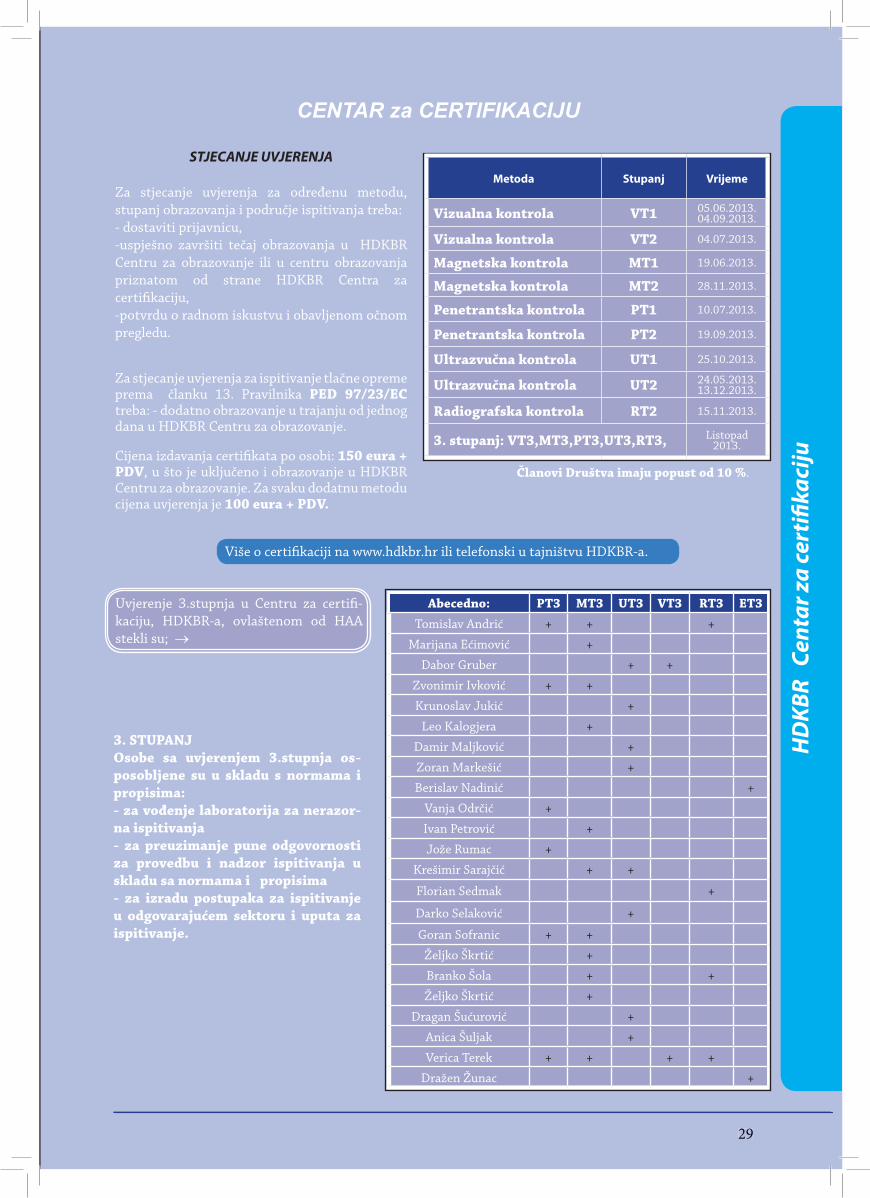
2929
CENTAR za CERTIFIKACIJU
Više o certifi kaciji na www.hdkbr.hr ili telefonski u tajništvu HDKBR-a.
Metoda Stupanj Vrijeme
Vizualna kontrola VT1 05.06.2013.04.09.2013.
Vizualna kontrola VT2 04.07.2013.
Magnetska kontrola MT1 19.06.2013.
Magnetska kontrola MT2 28.11.2013.
Penetrantska kontrola PT1 10.07.2013.
Penetrantska kontrola PT2 19.09.2013.
Ultrazvučna kontrola UT1 25.10.2013.
Ultrazvučna kontrola UT2 24.05.2013.13.12.2013.
Radiografska kontrola RT2 15.11.2013.
3. stupanj: VT3,MT3,PT3,UT3,RT3, Listopad 2013.
STJECANJE UVJERENJA
Za stjecanje uvjerenja za određenu metodu, stupanj obrazovanja i područje ispitivanja treba: - dostaviti prijavnicu, -uspješno završiti tečaj obrazovanja u HDKBR Centru za obrazovanje ili u centru obrazovanja priznatom od strane HDKBR Centra za certifi kaciju,-potvrdu o radnom iskustvu i obavljenom očnom pregledu.
Za stjecanje uvjerenja za ispitivanje tlačne opreme prema članku 13. Pravilnika PED 97/23/EC treba: - dodatno obrazovanje u trajanju od jednog dana u HDKBR Centru za obrazovanje.
Cijena izdavanja certifi kata po osobi: 150 eura + PDV, u što je uključeno i obrazovanje u HDKBR Centru za obrazovanje. Za svaku dodatnu metodu cijena uvjerenja je 100 eura + PDV.
Članovi Društva imaju popust od 10 %.
HD
KBR
Cen
tar z
a ce
rtifi
kaci
ju
Abecedno: PT3 MT3 UT3 VT3 RT3 ET3Tomislav Andrić + + +
Marijana Ećimović +
Dabor Gruber + +
Zvonimir Ivković + +
Krunoslav Jukić +
Leo Kalogjera +
Damir Maljković +
Zoran Markešić +
Berislav Nadinić +
Vanja Odrčić +
Ivan Petrović +
Jože Rumac +
Krešimir Sarajčić + +
Florian Sedmak +
Darko Selaković +
Goran Sofranic + +
Željko Škrtić +
Branko Šola + +
Željko Škrtić +
Dragan Šućurović +
Anica Šuljak +
Verica Terek + + + +
Dražen Žunac +
3. STUPANJOsobe sa uvjerenjem 3.stupnja os-posobljene su u skladu s normama i propisima: - za vođenje laboratorija za nerazor-na ispitivanja- za preuzimanje pune odgovornosti za provedbu i nadzor ispitivanja u skladu sa normama i propisima- za izradu postupaka za ispitivanje u odgovarajućem sektoru i uputa za ispitivanje.
Uvjerenje 3.stupnja u Centru za certifi -kaciju, HDKBR-a, ovlaštenom od HAA stekli su; →
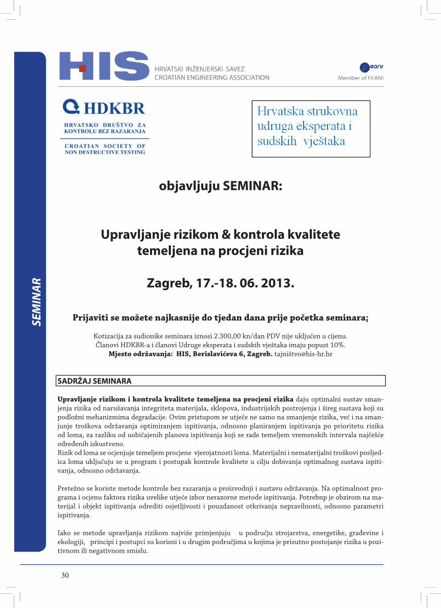
30
SEM
INAR
objavljuju SEMINAR:
Upravljanje rizikom & kontrola kvalitete temeljena na procjeni rizika
Zagreb, 17.-18. 06. 2013.
Prijaviti se možete najkasnije do tjedan dana prije početka seminara;
Kotizacija za sudionike seminara iznosi 2.300,00 kn/dan PDV nije uključen u cijenu.Članovi HDKBR-a i članovi Udruge eksperata i sudskih vještaka imaju popust 10%.
Mjesto održavanja: HIS, Berislavićeva 6, Zagreb. tajniš[email protected]
SADRŽAJ SEMINARA
Upravljanje rizikom i kontrola kvalitete temeljena na procjeni rizika daju optimalni sustav sman-jenja rizika od narušavanja integriteta materijala, sklopova, industrijskih postrojenja i šireg sustava koji su podložni mehanizmima degradacije. Ovim pristupom se utječe ne samo na smanjenje rizika, već i na sman-junje troškova održavanja optimiranjem ispitivanja, odnosno planiranjem ispitivanja po prioritetu rizika od loma, za razliku od uobičajenih planova ispitivanja koji se rade temeljem vremenskih intervala najčešće određenih iskustveno.Rizik od loma se ocjenjuje temeljem procjene vjerojatnosti loma. Materijalni i nematerijalni troškovi posljed-ica loma uključuju se u program i postupak kontrole kvalitete u cilju dobivanja optimalnog sustava ispiti-vanja, odnosno održavanja.
Pretežno se koriste metode kontrole bez razaranja u proizvodnji i sustavu održavanja. Na optimalnost pro-grama i ocjenu faktora rizika uvelike utjeće izbor nerazorne metode ispitivanja. Potrebnp je obzirom na ma-terijal i objekt ispitivanja odrediti osjetljivosti i pouzdanost otkrivanja nepravilnosti, odnosno parametri ispitivanja.
Iako se metode upravljanja rizikom najviše primjenjuju u području strojarstva, energetike, građevine i ekologiji, principi i postupci su korisni i u drugim područjima u kojima je prisutno postojanje rizika u pozi-tivnom ili negativnom smislu.
31
SEM
INAR
SEMINAR JE NAMJENJEN
Osobama odgovornim za sigurnost proizvoda, te koje rade na prilagodbi normi i legislative prema EUPredstavnicima industrijskih objekata i voditeljima ispitivanja i kontrole kvalitete, Osobama koje provode kontrolu kvalitete metodama nerazornih ispitivanja, Svima koji sudjeluju u sustavu osiguravanja kvalitete i sigurnosti tehničkih proizvoda, projektantima tlačnih posuda i konstrukcija povećanog rizika (spremnici, liftovi, žičare, saobraćaj....)Svima koji dolaze u susret sa potrebom ocjene rizika u industriji. Naročito je važno poznavanje principa up-ravljanja rizikom na razini upravnih tijela i rukovodećih kadrova u gospodarstvu radi uvida u mogućnosti i ocjenu odgovornosti, te kadrova koji nose odgovornost pokrivanja rizika i eventualnih posljedica uslijed krivih procjena.
PREDAVAČI
1.mr.sc. Predrag Dukić, dis Matkonerg, Stručnjak za rizik sa 30 g. Iskustva u energetici i naftnoj indus-triji, Certificitan za RBI na TWI Cambridge, UK, Član tehničkog odbora Pressure and process Plant (TG5) TWI Cambridge, UK. 2.Dr.sc. Aco Šikanić,dis Brodarski institut, voditelj odjela obnovljivi stalni sudski vještak za in-dustriju.3. Ines Dukić, dipl.inž.fizike, stručnjak sa dugogodišnjim iskustvom na NDT ispitivanju energet-skih i naftnih postrojenja 4. Silvester Jeršić, tehnički direktor HESS (hihroelektrane na donjoj savi – SLO)5. mr.sc.Rajko Orlić, dis, Generali osiguranje, voditelj sektora osiguranja industrijskih objekata
PROGRAM
1 dan: 8:30-9:00 Prijava sudionika9:00-10:30 Upravljanje rizikom10:30-11:00 odmor 11:00-12:30 Određivanje mehanizma degradacije12:30-13:30 odmor za ručak13:30-15:00 Vjerojatnost loma, određivanje rizika15:00-15:30 Radni odmor-diskusija-pitanja 15:30-17:00 Uloge, odgovornosti, kvalifikacija17:00-18:00 Primjena u EU, RH i šire
2.dan:9:00-10:30 Nerazorne metode u programu upravljanja rizikom10:30-11:00 odmor11:00-12:30 Osjetljivost, pouzdanost, mjerna nesigurnost 12:30-13:30 odmor za ručak13:30-15:00 Demonstracija metoda i primjena 15:00-15:30 Radni odmor-diskusija-pitanja 15:30-17:00 Korištenje rezultata kontrole u izradi programa upravljanja rizikom17:00-18:00 Tretman rizika na sudu i kod osiguravajućih društava
Učesnici seminara će dobiti potrebne materijale koji im omogućavaju praćenje seminara i za kasnije korištenje u primjeni upravljanja rizikom
Po završetku seminara učesnici dobivaju potvrdu o prisustvovanju seminaru.
32
PRO
ČITA
LI S
MO
ZA
VAS
ToFD ISPITIVANJE FAZNIM SONDAMA
Pripremila za INFO: Mr.sc. Irena Leljak
Intoduction
Phased arrays (PA) are mostly used in Pulse Echo mode of ultrasonic inspection i.e. they are very seldom considered as probes for detection of diffrated signals, wheather in for-ward diffraction as in ToFD technique or backward. The con-sideration thus is given to appearance of only three articles at two WCNDT in which the innovative approach is explained consisting of employing PA probes for diffraction techniques The main topics of articles named in references , are present-ed herein.
Uvod
Fazne sonde (PA) u pravilu se koriste za ultrazvučno ispitivanje metodom odjeka i ponekad za tandemsku tehniku, a vrlo se rijetko upotrebljavaju u ToFD tehnici ispitivanja (tehnici ispitivanja difrakcijom ToFD -Time-of-flight diffraction), stoga je vrlo zanimljivo i važno obra-titi pozornost na inovativni pristup korištenja PA u ToFD tehnici. U ovom osvrtu biti će iznesene glavne postavke ToFD tehnike s PA - sondama što se nalaze u trima člancima navedenima u referencijama. Valja naglasiti da spome-nuta tri članka nisu odabrana između ostalih članaka s istom temom, već su to jedina tri članka pronađena na dvije posljednje svjetske NDT konferencije. Prikaz ovih članaka uvršten je u INFO zbog pravovremenog sagledavanja potrebnog ulaganja u novu mogućnost ultrazvučnog ispitivanja, koja sigurno znatno doprinosi unapređenju pouzdanosti ispitivanja.
Referencije - prikazani radovi:
1. C. Brillon1 , T. Armitt 2 i O. Dupuis1 “ToFD Inspection with Phased Arrays“ 17th WCNDT , Oct. 2008, Shanghai. 1Olympus NDT Inc., Canada, 2Lavender International NDT,
2. UK.M. Moles1 i S. Labbé1 “ A complete solution for weld inspection – Phased ar-rays and Diffraction sizing“ 17th WCNDT , Oct. 2008, Shanghai. 1Olympus NDT Inc., Canada
3. F. Laprise1, J.Berlanger1, G.Maes1 “ Sectorial scan PA combined with ToFD - A robust weld inspection“ 18th WCNDT, April 2012, Durban.1 Zetec Québec, Canada.
Sažeti prikaz navedenih radova
Osnovna prednost ToFD tehnike s obzirom na ultrazvučno ispitivanje metodom odjeka jest mogućnost
otkrivanja pukotina neovisno o njihovoj orijentaciji.Ta je značajka neupitno važna u kontroli te se ulažu veliki napori da se umanje ili izbjegnu glavni nedostaci ToFD tehnike koji jesu:
• povećavanje pogreške procjenjivanja vremenaprijma difrakcijskog signala povećanjem ulaznog kuta ultrazvučnog snopa u objekt ispitivanja • dužina mrtve zone površinskog vala koja zastire difrakcijske signale pristigle unutar te zone • pogrešna procjena položaja nepravilnosti kada se nepravilnost u objektu ne nalazi u presjeku polo-vine razmaka između sondi
Navedeni nedostaci ToFD tehnike ispitivanja rješavaju se višestrukim različitim pretraživanjima jednog područja, što je vrlo dugotrajan i zahtjevan postupak obzirom na potrebu primjene različitih razmaka između sondi, različitih ulaznih kutova ultrazvučnog vala u objekt ispitivanja, kao i različitih oblika ultrazvučnog snopa. Paralelno, znatno razvijena tehnologija ultrazvučnog ispitivanja s PA ponukala je autore navedenih radova da pristupe realizaciji ideje o provedbi ToFD s PA - sondama.
Elektronsko oblikovanje izlaznog snopa fazne sonde postignutog interferencijom ultrazvučnih valova s po-jedinih neovisnih pretvornika fazne sonde obuhvaća promjenu izlazne točke snopa, promjenu smjera, širine, fokusa i dometa snopa, te se višestruko pretraživanje određenog područja provodi bez fizičkog premještanja ispitnog sklopa. To peterostruko ubrzava ispitivanje s PA s obzirom na do sada već konvencionalno ToFD ispiti-vanje. Može se reći da je jedino brzina ultrazvučnog vala parametar koji ograničava brzinu ispitivanja s PA.
Programska podrška za ToFD s PA - sondama sadrži sve segmente ispitivanja. Započinje od pripreme ispitivanja do sinteze mnoštva podataka koji se pohranjuju br-zinom od 10 Mb/s u datoteke kapaciteta od čak 20 GB, što omogućava brzu interpretaciju rezultata ispitivanja koji se dobivaju u zornim prikazima i raznim potrebnim projekcijama.
Od velikog je interesa i korištenje PA - sondi za prihvaćanje povratnog difrakcijskog signala. U tom se slučaju koristi jedna sonda, a tehnika se primjenjuje za specifično ispitivanje površinskih pukotina; registrira se značajno povećanje omjera signal/šum od čak 20 dB.
Na temelju navedenih radova može se ustanoviti da se tehnika ToFD s PA - sondama razvija vrlo brzo i to in-strumentalno i programski te se očekuje da će se tehnika vrlo brzo prihvatiti u industriji, temeljem mogućnosti ot-krivanja nepravilnosti, brzine i pouzdanosti ispitivanja.
Završni komentar
Objavljivanjem postavki triju navedenih inovativnih članaka u HDKBR-info, željelo se ukazati na dodatni razvoj ToFD ispitivanja upotrebom PA - sondi, potak-nuti na praćenje razvoja ove tehnike i na uključivanje u istraživanje mogućnosti ove nove i obećavajuće tehnike ultrazvučnog ispitivanja.
33
With the thermal imager testo 885 you identify thermal abnormalitieseven more precisely and effectively.• SuperResolution thermal images with 640 x 480 pixels (320 x 240 pixel detector)• Flexible handling thanks to ergonomic rotatable handle and display• SiteRecognition technology: Measurement site recognition withautomatic image management www.testo.com/885
Uninterruptedproduction.