hci theory of operations v1 - netapp.com · hci solution, eliminates performance variance in the...
TRANSCRIPT
White Paper
NetApp HCI Theory of Operations Version 1.3
Aaron Patten, NetApp
June 2018 | WP-7261
Abstract
Hyper converged infrastructure (HCI) has promised the industry simplicity of deployment, ease
of operation, and scale. However, the inherent design of most modern HCI systems limits their
ability to deliver on one or more of these promises.
This white paper describes how the NetApp HCI system brings simplicity of configuration,
efficiency of operation, and elasticity of scale together in a single product.

2 NetApp HCI Theory of Operations © 2018 NetApp, Inc. All rights reserved.
TABLE OF CONTENTS
1 HCI and the Theory of Everything ....................................................................................................... 4
1.1 Performance Guarantee ................................................................................................................................. 4
1.2 Enterprise Scale .............................................................................................................................................. 4
1.3 Streamline Operations .................................................................................................................................... 4
1.4 Configuration ................................................................................................................................................... 5
2 System Design and Architecture ........................................................................................................ 6
2.1 Overview ......................................................................................................................................................... 6
2.2 Networking ...................................................................................................................................................... 6
2.3 Storage Components ...................................................................................................................................... 8
2.4 vSphere Components ................................................................................................................................... 12
3 Expanding NetApp HCI ...................................................................................................................... 21
3.1 EasyScale ..................................................................................................................................................... 21
4 Mixed Workloads ................................................................................................................................ 23
4.1 Test Configuration ......................................................................................................................................... 23
4.2 Results .......................................................................................................................................................... 25
5 Extending NetApp HCI ....................................................................................................................... 26
5.1 NetApp ONTAP Select .................................................................................................................................. 26
5.2 NetApp SnapMirror ....................................................................................................................................... 27
5.3 vRealize Orchestrator Plug-In ....................................................................................................................... 28
5.4 External Host Access .................................................................................................................................... 29
5.5 HCICollector Project ..................................................................................................................................... 29
Conclusion ................................................................................................................................................ 30
Where to Find Additional Information .................................................................................................... 31
Version History ......................................................................................................................................... 31
LIST OF TABLES
Table 1) NetApp HCI configuration storage nodes. ........................................................................................................ 5
Table 2) NetApp HCI configuration compute nodes. ...................................................................................................... 5
Table 3) Node interface requirements. ........................................................................................................................... 7
Table 4) vSphere components. .................................................................................................................................... 12
Table 5) Mongo replica set cluster VMs. ...................................................................................................................... 24
Table 6) Yahoo! Cloud Serving Benchmark (YCSB) client-server VM. ........................................................................ 24
3 NetApp HCI Theory of Operations © 2018 NetApp, Inc. All rights reserved.
Table 7) SQL VMs. ....................................................................................................................................................... 24
Table 8) VDI VMs. ........................................................................................................................................................ 24
LIST OF FIGURES
Figure 1) Minimum configuration. ................................................................................................................................... 5
Figure 2) HCI components. ............................................................................................................................................ 6
Figure 3) ZeroConf. ........................................................................................................................................................ 8
Figure 4) NetApp vCenter Plug-in for HCI. ..................................................................................................................... 9
Figure 5) NMA options.................................................................................................................................................. 10
Figure 6) NetApp Monitoring Agent. ............................................................................................................................. 11
Figure 7) Active IQ capacity forecasting. ...................................................................................................................... 11
Figure 8) Active IQ vCenter reporting. .......................................................................................................................... 12
Figure 9) Compute node physical to logical port map (VSS). ....................................................................................... 13
Figure 10) VMkernel binding. ....................................................................................................................................... 14
Figure 11) Management port groups configuration on VMware standard switches. ..................................................... 14
Figure 12) vMotion and VM_Network configuration on VMware standard switches. .................................................... 15
Figure 13) iSCSI-A and iSCSI-B configuration on VMware standard switches. ............................................................ 15
Figure 14) VDS uplink names. ...................................................................................................................................... 16
Figure 15) Compute node physical to logical port map (VDS). ..................................................................................... 16
Figure 16) Management port groups configuration on VMware distributed switches. .................................................. 17
Figure 17) vMotion and VM_Network configuration on VMware distributed switches. ................................................. 17
Figure 18) iSCSI-A configuration on VMware distributed switches. .............................................................................. 18
Figure 19) iSCSI-B configuration on VMware distributed switches. .............................................................................. 18
Figure 20) Host IQN: iSCSI name. ............................................................................................................................... 18
Figure 21) Volume Access Group. ............................................................................................................................... 19
Figure 22) Default datastores. ...................................................................................................................................... 20
Figure 23) Create datastore. ........................................................................................................................................ 20
Figure 24) Adding nodes with EasyScale. .................................................................................................................... 22
Figure 25) Mixed workloads. ........................................................................................................................................ 23
Figure 26) VDI boot storm with QoS disabled. ............................................................................................................. 25
Figure 27) VDI boot storm with QoS enabled. .............................................................................................................. 26
Figure 28) Data Fabric—ONTAP Select. ...................................................................................................................... 27
Figure 29) ONTAP Select on HCI. ................................................................................................................................ 27
Figure 30) SnapMirror. ................................................................................................................................................. 28
Figure 31) vRO workflows. ........................................................................................................................................... 28
Figure 32) External host access. .................................................................................................................................. 29
Figure 33) HCICollector interface. ................................................................................................................................ 30
4 NetApp HCI Theory of Operations © 2018 NetApp, Inc. All rights reserved.
1 HCI and the Theory of Everything
NetApp® HCI is an enterprise-scale hyper converged infrastructure solution that is ideally suited for
customers who are looking to break free from first-generation HCI limitations.
NetApp HCI customers can run multiple applications with guaranteed performance to confidently deploy
resources across your entire data center. This architecture allows you to deploy your infrastructure by
simplifying management and independently scaling both compute and storage resources. NetApp HCI is
Data Fabric ready out of the box for easy access to all your data across any public, private, or hybrid
cloud. By moving to NetApp HCI, IT organizations can transform their data center, driving operational
efficiencies and reducing costs.
The Data Fabric is a software-defined approach from NetApp for data management that enables
businesses to connect disparate data management and storage resources. NetApp HCI can streamline
data management between on-premises and cloud storage for enhanced data portability, visibility, and
protection.
1.1 Performance Guarantee
A common challenge for a data center is delivering predictable performance, a goal complicated by
running multiple applications that share the same infrastructure. An application interfering with other
applications creates performance degradations, causing IT administrators to spend valuable time
troubleshooting the environment. Mainstream applications, such as virtual desktop infrastructure (VDI)
and database applications, have unique I/O patterns that can affect one another’s performance during
normal operations when they are deployed in a shared environment.
The NetApp HCI quality of service (QoS) feature enables fine-grained control of performance for every
application, eliminating noisy neighbors, meeting unique performance needs, allowing higher utilization of
infrastructure, and satisfying performance SLAs. The storage architecture, which is part of the NetApp
HCI solution, eliminates performance variance in the context of data locality because the data is
distributed across all the nodes in the HCI cluster.
1.2 Enterprise Scale
Unlike previous generations of HCI, which have fixed resource ratios, NetApp HCI scales compute and
storage resources independently. Independent scaling avoids costly and inefficient overprovisioning and
simplifies capacity and performance planning. NetApp HCI is an enterprise-scale hyper converged
infrastructure solution that runs on innovative NetApp SolidFire® Element® OS technology and is delivered
on an architecture designed by NetApp. NetApp HCI comes in 2RU x 4-node building blocks (chassis) in
small, medium, and large storage and compute configurations that can be mixed and matched. HCI can
be scaled so that you can rapidly meet changing business needs on your terms.
1.3 Streamline Operations
A common goal of IT organizations is to automate all routine tasks and eliminate the risk of user errors
associated with manual operations. Automation allows you to focus valuable resources on higher value
priorities that drive business efficiencies. The NetApp Deployment Engine (NDE) streamlines day zero
installation from hours to minutes. Centralized management through the vCenter Plug-in gives you full
control over your infrastructure with an intuitive UI. A robust suite of APIs allows you to seamlessly
integrate higher-level management, orchestration, backup, and disaster-recovery tools.

5 NetApp HCI Theory of Operations © 2018 NetApp, Inc. All rights reserved.
1.4 Configuration
NetApp HCI is available with small, medium, or large configuration options for both compute and storage.
The nodes are similar to a small blade that sits inside a chassis. A minimum starting configuration must
have four storage nodes and two compute nodes.
Figure 1) Minimum configuration.
As shown in the configuration information in Table 1, each storage node can deploy 5.5TB to 44TB of
effective capacity. From a compute node perspective, 16 to 36 CPU cores and 384GB to 768GB of RAM
are available, as shown in Table 2.
Table 1) NetApp HCI configuration storage nodes.
Small Medium Large
RU 1RU, half-width 1RU, half-width 1RU, half-width
CPU E5-2620 v4: 8C at 2.1GHz E5-2650 v4: 12C at 2.2GHz E5-2695 v4: 18C at 2.1GHz
Boot device 1 x 240GB MLC 1 x 240GB MLC 1 x 240GB MLC
Base networking
2 25/10GbE SFP28 /SFP+
2 1GbE RJ45
2 25/10GbE SFP28 /SFP+
2 1GbE RJ45
2 25/10GbE SFP28 /SFP+
2 1GbE RJ45
SSD 6 480GB 6 960GB 6 1.9TB
Effective block capacity
5.5TB–11TB 11TB–22TB 22TB–44TB
Table 2) NetApp HCI configuration compute nodes.
Small Medium Large
RU 1RU, half-width 1RU, half-width 1RU, half-width
Cores for VMs 16 24 36
CPU E5-2620 v4: 8C at 2.1GHz E5-2650 v4: 12C at 2.2GHz E5-2695 v4: 18C at 2.1GHz
Memory 384GB 512GB 768GB
Boot device 1 240GB MLC 1 240GB MLC 1 240GB MLC
6 NetApp HCI Theory of Operations © 2018 NetApp, Inc. All rights reserved.
Small Medium Large
Base networking
4 25/10GbE SFP28 /SFP+
2 1GbE RJ45
4 25/10GbE SFP28 /SFP+
2 1GbE RJ45
4 25/10GbE SFP28 /SFP+
2 1GbE RJ45
For example, for a minimum-size starting solution, a configuration with two small compute nodes and four
small storage nodes could have 32 cores with 768GB of memory and from 22TB to 44TB of effective
capacity. As requirements change, you can add more compute or storage nodes of any size to the
chassis independently of each other. The flexibility to add only compute or storage nodes provides unique
scalability options for building an efficient and agile cloud in your data center for various use cases.
2 System Design and Architecture
2.1 Overview
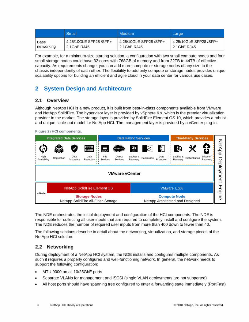
Although NetApp HCI is a new product, it is built from best-in-class components available from VMware
and NetApp SolidFire. The hypervisor layer is provided by vSphere 6.x, which is the premier virtualization
provider in the market. The storage layer is provided by SolidFire Element OS 10, which provides a robust
and unique scale-out model for NetApp HCI. The management layer is provided by a vCenter plug-in.
Figure 2) HCI components.
The NDE orchestrates the initial deployment and configuration of the HCI components. The NDE is
responsible for collecting all user inputs that are required to completely install and configure the system.
The NDE reduces the number of required user inputs from more than 400 down to fewer than 40.
The following sections describe in detail about the networking, virtualization, and storage pieces of the
NetApp HCI solution.
2.2 Networking
During deployment of a NetApp HCI system, the NDE installs and configures multiple components. As
such it requires a properly configured and well-functioning network. In general, the network needs to
support the following configuration:
• MTU 9000 on all 10/25GbE ports
• Separate VLANs for management and iSCSI (single VLAN deployments are not supported)
• All host ports should have spanning tree configured to enter a forwarding state immediately (PortFast)
NetApp SolidFire Element OS VMware ESXi
Storage Nodes
NetApp SolidFire All-Flash Storage
Compute Node
NetApp Architected and Designed
mNode
VMware vCenter
Integrated Data Services Data Fabric Services Third-Party Services
High
Availability
Backup &
RecoveryReplication
Data
Assurance
Data
Reduction
File
Services
Object
Services
Backup &
RecoveryReplication
Data
ProtectionOrchestration
Disaster
Recovery
NetA
pp D
eplo
ymen
t En
gin
e
7 NetApp HCI Theory of Operations © 2018 NetApp, Inc. All rights reserved.
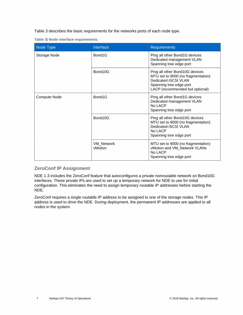
Table 3 describes the basic requirements for the networks ports of each node type.
Table 3) Node interface requirements.
Node Type Interface Requirements
Storage Node Bond1G Ping all other Bond1G devices Dedicated management VLAN Spanning tree edge port
Bond10G Ping all other Bond10G devices MTU set to 9000 (no fragmentation) Dedicated iSCSI VLAN Spanning tree edge port LACP (recommended but optional)
Compute Node Bond1G Ping all other Bond1G devices Dedicated management VLAN No LACP Spanning tree edge port
Bond10G Ping all other Bond10G devices MTU set to 9000 (no fragmentation) Dedicated iSCSI VLAN No LACP Spanning tree edge port
VM_Network vMotion
MTU set to 9000 (no fragmentation) vMotion and VM_Network VLANs No LACP Spanning tree edge port
ZeroConf IP Assignment
NDE 1.3 includes the ZeroConf feature that autoconfigures a private nonroutable network on Bond10G
interfaces. These private IPs are used to set up a temporary network for NDE to use for initial
configuration. This eliminates the need to assign temporary routable IP addresses before starting the
NDE.
ZeroConf requires a single routable IP address to be assigned to one of the storage nodes. This IP
address is used to drive the NDE. During deployment, the permanent IP addresses are applied to all
nodes in the system.
8 NetApp HCI Theory of Operations © 2018 NetApp, Inc. All rights reserved.
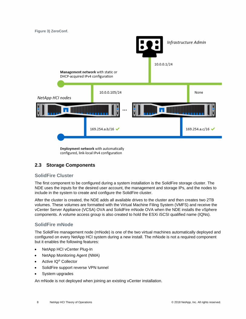
Figure 3) ZeroConf.
2.3 Storage Components
SolidFire Cluster
The first component to be configured during a system installation is the SolidFire storage cluster. The
NDE uses the inputs for the desired user account, the management and storage IPs, and the nodes to
include in the system to create and configure the SolidFire cluster.
After the cluster is created, the NDE adds all available drives to the cluster and then creates two 2TB
volumes. These volumes are formatted with the Virtual Machine Filing System (VMFS) and receive the
vCenter Server Appliance (VCSA) OVA and SolidFire mNode OVA when the NDE installs the vSphere
components. A volume access group is also created to hold the ESXi iSCSI qualified name (IQNs).
SolidFire mNode
The SolidFire management node (mNode) is one of the two virtual machines automatically deployed and
configured on every NetApp HCI system during a new install. The mNode is not a required component
but it enables the following features:
• NetApp HCI vCenter Plug-In
• NetApp Monitoring Agent (NMA)
• Active IQ® Collector
• SolidFire support reverse VPN tunnel
• System upgrades
An mNode is not deployed when joining an existing vCenter installation.

9 NetApp HCI Theory of Operations © 2018 NetApp, Inc. All rights reserved.
NetApp vCenter Plug-In for HCI
The NetApp vCenter Plug-In (VCP) is the management focal point for the HCI system. It brings day-to-
day storage management tasks into vCenter and enables the NetApp Monitoring Agent.
Figure 4) NetApp vCenter Plug-in for HCI.
All common day-to-day storage management tasks are available in the VCP. The VCP has five sections
related to SolidFire integration with vCenter:
• Reporting. Includes system overview, event logs, alerts, and running tasks on the SolidFire cluster.
• Management. Tasks for creating, deleting, and managing datastores and SolidFire volumes, accounts, access groups, and ESXi initiators. QoS policies can also be configured here.
• Data protection. Management of SolidFire snapshots, group snapshots, and snapshot schedules.
• Cluster. Tasks for adding and removing SolidFire nodes to and from the cluster as well as managing virtual networks.
• VMware Virtual Volumes (VVols). Reporting and management of VVols, storage containers, and protocol endpoints. The VVols feature is not enabled by default. For information about enabling and configuring VVols, see TR-4642: NetApp SolidFire VMware vSphere Virtual Volumes for SolidFire Storage Configuration Guide.

10 NetApp HCI Theory of Operations © 2018 NetApp, Inc. All rights reserved.
NetApp Monitoring Agent
The NMA is a component of the VCP and consolidates the events from the compute and storage
components into a single view that can easily be consumed in vCenter. NMA features can be enabled or
disabled from the SolidFire management node (mNode) interface.
Figure 5) NMA options.
The NMA includes the following options:
• Run alert monitor tests. Tests the functionality of the NMA agent.
• Collect alerts. Toggles the collection of all alerts. Must be turned on to enable any of the alert collection options. Enabled by default.
• Collect best practice alerts. Enables reporting of best practice alerts from the SolidFire cluster to vCenter. This reporting includes network misconfigurations and other issues that are indicative of a suboptimal configuration. Disabled by default.
• Send support data to Active IQ. Sends vCenter alarms to Active IQ. Required for SolidFire to proactively engage support issues. Enabled by default.
• Send compute node data to Active IQ. Sends vCenter telemetry data and logs to Active IQ. This option enables Active IQ to collect support bundles and provide reporting specific to vCenter in Active IQ. Enabled by default.
11 NetApp HCI Theory of Operations © 2018 NetApp, Inc. All rights reserved.
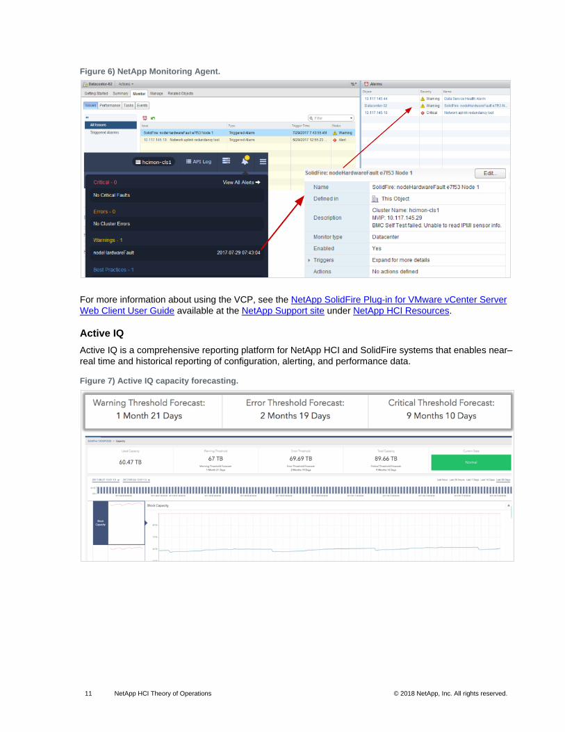
Figure 6) NetApp Monitoring Agent.
For more information about using the VCP, see the NetApp SolidFire Plug-in for VMware vCenter Server
Web Client User Guide available at the NetApp Support site under NetApp HCI Resources.
Active IQ
Active IQ is a comprehensive reporting platform for NetApp HCI and SolidFire systems that enables near–
real time and historical reporting of configuration, alerting, and performance data.
Figure 7) Active IQ capacity forecasting.

12 NetApp HCI Theory of Operations © 2018 NetApp, Inc. All rights reserved.
Figure 8) Active IQ vCenter reporting.
More information about using Active IQ is available online at Active IQ Help.
2.4 vSphere Components
The NDE completely automates the installation and configuration of vSphere components and prepares
the system according to established best practices. The current supported vCenter versions are 6.0U3a
and 6.5U1.
Note: These versions do not contain the required patches for Spectre or Meltdown. For more information, see the following VMware KB article: https://kb.vmware.com/s/article/52245.
Table 4) vSphere components.
Component Automation Tasks
ESXi 1. Install ESXi 6.0 U3a or ESXi 6.5 U1
2. Create vSwitches and port groups
3. Enable software iSCSI adapter
4. Configure VMkernel ports for vMotion and iSCSI
5. Configure VMkernel port binding for iSCSI
6. Add dynamic discovery address for SolidFire storage virtual IP (SVIP) address
7. Add ESXi iSCSI IQN to SolidFire volume access group
8. Provision two VMFS datastores for vCenter and the SolidFire mNode
vCenter 1. Deploy vCenter VCSA 6.0.0-5202527 or 6.5.0-5973321
2. Create default data center and cluster objects
3. Enable and configure Distributed Resource Scheduler (DRS) and high availability (HA)
4. Install and register the vCenter HCI plug-in
5. Register the SolidFire system with the vCenter plug-in
6. Configure NetApp Monitoring and Alerting (NMA)
The NDE can deploy with either VMware distributed switches (VDS) or VMware standard switches (VSS).
13 NetApp HCI Theory of Operations © 2018 NetApp, Inc. All rights reserved.
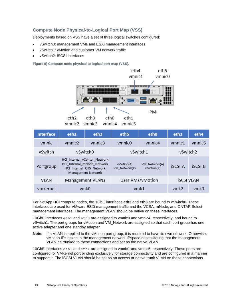
Compute Node Physical-to-Logical Port Map (VSS)
Deployments based on VSS have a set of three logical switches configured:
• vSwitch0: management VMs and ESXi management interfaces
• vSwitch1: vMotion and customer VM network traffic
• vSwitch2: iSCSI interfaces
Figure 9) Compute node physical to logical port map (VSS).
For NetApp HCI compute nodes, the 1GbE interfaces eth2 and eth3 are bound to vSwitch0. These
interfaces are used for VMware ESXi management traffic and the VCSA, mNode, and ONTAP Select
management interfaces. The management VLAN should be native on these interfaces.
10GbE interfaces eth5 and eth0 are assigned to vmnic0 and vmnic4, respectively, and bound to
vSwitch1. The port groups for vMotion and VM_Network are assigned so that each port group has one
active adapter and one standby adapter.
Note: If a VLAN is applied to the vMotion port group, it is required to have its own network. Otherwise, vMotion IPs reside in the management network IPspace necessitating that the management VLAN be trunked to these connections and set as the native VLAN.
10GbE interfaces eth1 and eth4 are assigned to vmnic1 and vmnic5, respectively. These ports are
configured for VMkernel port binding exclusively for storage connectivity and are configured in a manner
to support it. The iSCSI VLAN should be set as an access or native trunk VLAN on these connections.

14 NetApp HCI Theory of Operations © 2018 NetApp, Inc. All rights reserved.
Figure 10) VMkernel binding.
Any additional customer VMs that require direct access to iSCSI storage hosted on the storage nodes
should have their network ports mapped to this vSwitch through an additional virtual machine port group.
The following figures show the NetApp HCI compute node virtual switch configuration when using
VMware standard switches.
Figure 11) Management port groups configuration on VMware standard switches.

15 NetApp HCI Theory of Operations © 2018 NetApp, Inc. All rights reserved.
Figure 12) vMotion and VM_Network configuration on VMware standard switches.
Figure 13) iSCSI-A and iSCSI-B configuration on VMware standard switches.
16 NetApp HCI Theory of Operations © 2018 NetApp, Inc. All rights reserved.
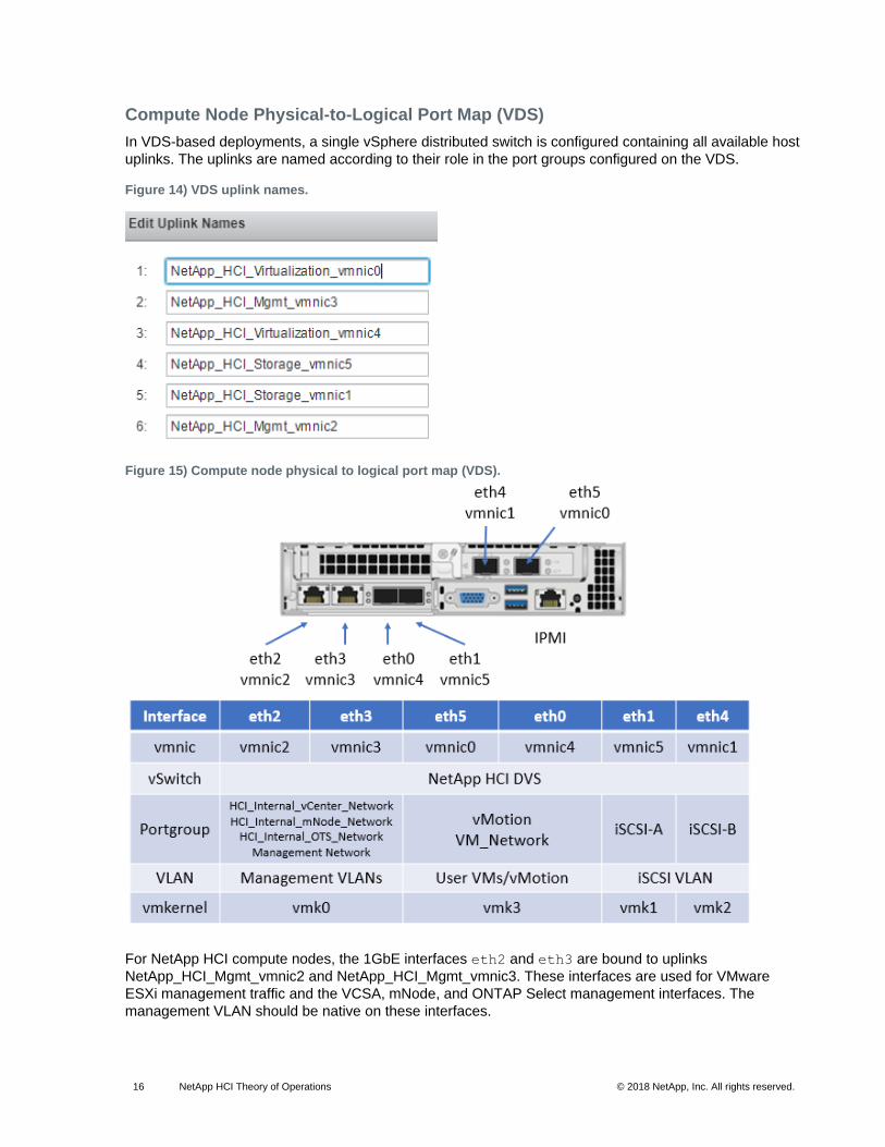
Compute Node Physical-to-Logical Port Map (VDS)
In VDS-based deployments, a single vSphere distributed switch is configured containing all available host
uplinks. The uplinks are named according to their role in the port groups configured on the VDS.
Figure 14) VDS uplink names.
Figure 15) Compute node physical to logical port map (VDS).
For NetApp HCI compute nodes, the 1GbE interfaces eth2 and eth3 are bound to uplinks
NetApp_HCI_Mgmt_vmnic2 and NetApp_HCI_Mgmt_vmnic3. These interfaces are used for VMware
ESXi management traffic and the VCSA, mNode, and ONTAP Select management interfaces. The
management VLAN should be native on these interfaces.
17 NetApp HCI Theory of Operations © 2018 NetApp, Inc. All rights reserved.
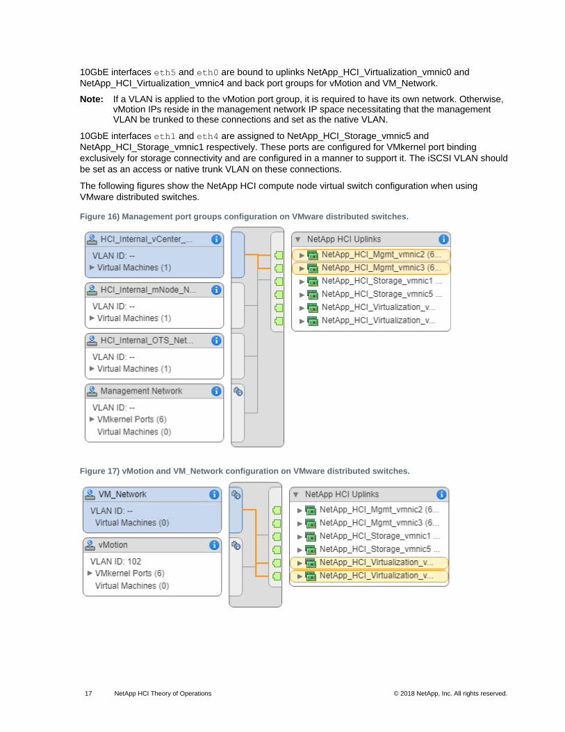
10GbE interfaces eth5 and eth0 are bound to uplinks NetApp_HCI_Virtualization_vmnic0 and
NetApp_HCI_Virtualization_vmnic4 and back port groups for vMotion and VM_Network.
Note: If a VLAN is applied to the vMotion port group, it is required to have its own network. Otherwise, vMotion IPs reside in the management network IP space necessitating that the management VLAN be trunked to these connections and set as the native VLAN.
10GbE interfaces eth1 and eth4 are assigned to NetApp_HCI_Storage_vmnic5 and
NetApp_HCI_Storage_vmnic1 respectively. These ports are configured for VMkernel port binding
exclusively for storage connectivity and are configured in a manner to support it. The iSCSI VLAN should
be set as an access or native trunk VLAN on these connections.
The following figures show the NetApp HCI compute node virtual switch configuration when using
VMware distributed switches.
Figure 16) Management port groups configuration on VMware distributed switches.
Figure 17) vMotion and VM_Network configuration on VMware distributed switches.
18 NetApp HCI Theory of Operations © 2018 NetApp, Inc. All rights reserved.
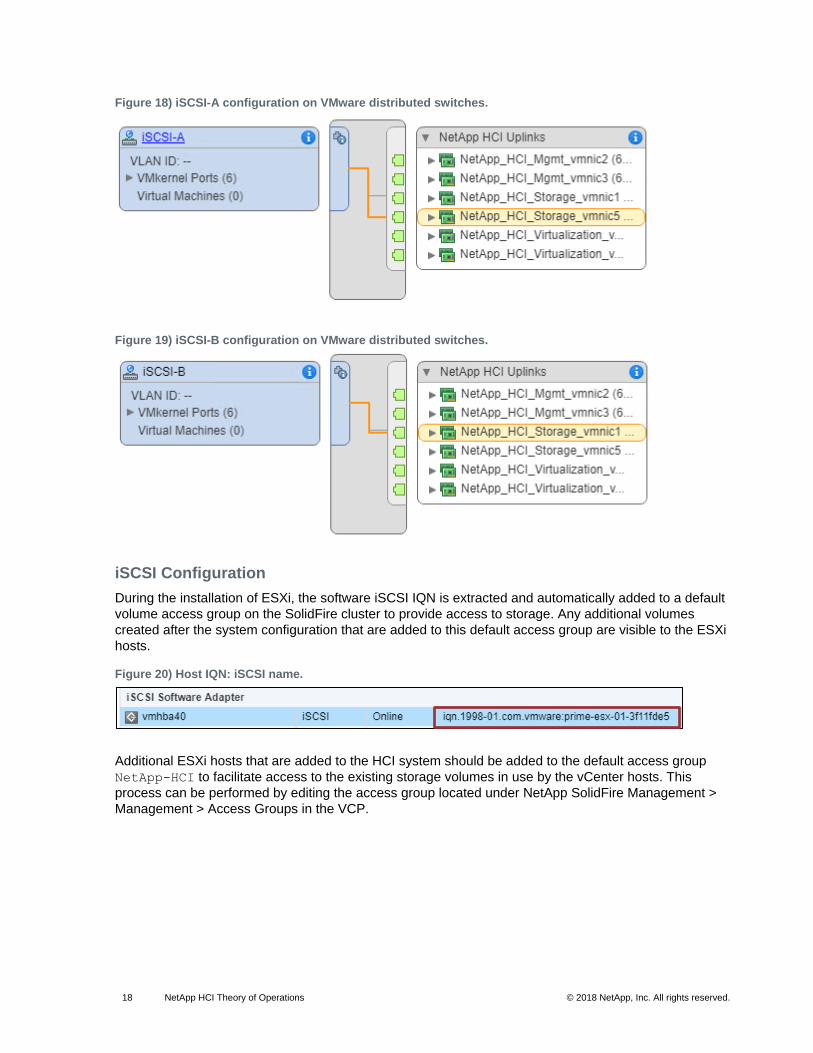
Figure 18) iSCSI-A configuration on VMware distributed switches.
Figure 19) iSCSI-B configuration on VMware distributed switches.
iSCSI Configuration
During the installation of ESXi, the software iSCSI IQN is extracted and automatically added to a default
volume access group on the SolidFire cluster to provide access to storage. Any additional volumes
created after the system configuration that are added to this default access group are visible to the ESXi
hosts.
Figure 20) Host IQN: iSCSI name.
Additional ESXi hosts that are added to the HCI system should be added to the default access group
NetApp-HCI to facilitate access to the existing storage volumes in use by the vCenter hosts. This
process can be performed by editing the access group located under NetApp SolidFire Management >
Management > Access Groups in the VCP.
19 NetApp HCI Theory of Operations © 2018 NetApp, Inc. All rights reserved.
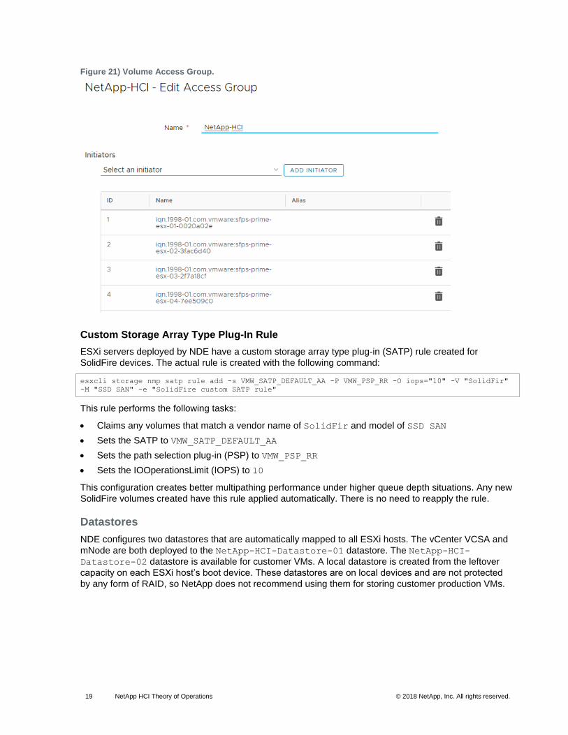
Figure 21) Volume Access Group.
Custom Storage Array Type Plug-In Rule
ESXi servers deployed by NDE have a custom storage array type plug-in (SATP) rule created for
SolidFire devices. The actual rule is created with the following command:
esxcli storage nmp satp rule add -s VMW_SATP_DEFAULT_AA -P VMW_PSP_RR -O iops="10" -V "SolidFir"
-M "SSD SAN" -e "SolidFire custom SATP rule"
This rule performs the following tasks:
• Claims any volumes that match a vendor name of SolidFir and model of SSD SAN
• Sets the SATP to VMW_SATP_DEFAULT_AA
• Sets the path selection plug-in (PSP) to VMW_PSP_RR
• Sets the IOOperationsLimit (IOPS) to 10
This configuration creates better multipathing performance under higher queue depth situations. Any new
SolidFire volumes created have this rule applied automatically. There is no need to reapply the rule.
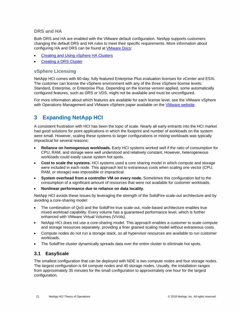
Datastores
NDE configures two datastores that are automatically mapped to all ESXi hosts. The vCenter VCSA and
mNode are both deployed to the NetApp-HCI-Datastore-01 datastore. The NetApp-HCI-
Datastore-02 datastore is available for customer VMs. A local datastore is created from the leftover
capacity on each ESXi host’s boot device. These datastores are on local devices and are not protected
by any form of RAID, so NetApp does not recommend using them for storing customer production VMs.
20 NetApp HCI Theory of Operations © 2018 NetApp, Inc. All rights reserved.
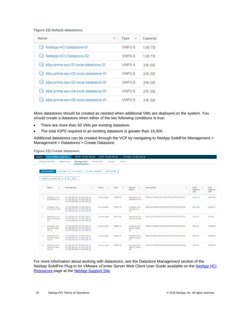
Figure 22) Default datastores.
More datastores should be created as needed when additional VMs are deployed on the system. You
should create a datastore when either of the two following conditions is true:
• There are more than 50 VMs per existing datastore.
• The total IOPS required in an existing datastore is greater than 15,000.
Additional datastores can be created through the VCP by navigating to NetApp SolidFire Management >
Management > Datastores > Create Datastore.
Figure 23) Create datastore.
For more information about working with datastores, see the Datastore Management section of the
NetApp SolidFire Plug-in for VMware vCenter Server Web Client User Guide available on the NetApp HCI
Resources page at the NetApp Support Site.
21 NetApp HCI Theory of Operations © 2018 NetApp, Inc. All rights reserved.
DRS and HA
Both DRS and HA are enabled with the VMware default configuration. NetApp supports customers
changing the default DRS and HA rules to meet their specific requirements. More information about
configuring HA and DRS can be found at VMware Docs:
• Creating and Using vSphere HA Clusters
• Creating a DRS Cluster
vSphere Licensing
NetApp HCI comes with 60-day, fully featured Enterprise Plus evaluation licenses for vCenter and ESXi.
The customer can license the vSphere environment with any of the three vSphere license levels:
Standard, Enterprise, or Enterprise Plus. Depending on the license version applied, some automatically
configured features, such as DRS or VDS, might not be available and must be unconfigured.
For more information about which features are available for each license level, see the VMware vSphere
with Operations Management and VMware vSphere paper available on the VMware website.
3 Expanding NetApp HCI
A consistent frustration with HCI has been the topic of scale. Nearly all early entrants into the HCI market
had good solutions for point applications in which the footprint and number of workloads on the system
were small. However, scaling these systems to larger configurations or mixing workloads was typically
impractical for several reasons:
• Reliance on homogenous workloads. Early HCI systems worked well if the ratio of consumption for CPU, RAM, and storage were well understood and relatively constant. However, heterogeneous workloads could easily cause system hot spots.
• Cost to scale the systems. HCI systems used a core sharing model in which compute and storage were included in each node. This approach led to extraneous costs when scaling one vector (CPU, RAM, or storage) was impossible or impractical.
• System overhead from a controller VM on every node. Sometimes this configuration led to the consumption of a significant amount of resources that were not available for customer workloads.
• Nonlinear performance due to reliance on data locality.
NetApp HCI avoids these issues by leveraging the strength of the SolidFire scale-out architecture and by
avoiding a core-sharing model:
• The combination of QoS and the SolidFire true scale-out, node-based architecture enables true mixed workload capability. Every volume has a guaranteed performance level, which is further enhanced with VMware Virtual Volumes (VVols).
• NetApp HCI does not use a core-sharing model. This approach enables a customer to scale compute and storage resources separately, providing a finer grained scaling model without extraneous costs.
• Compute nodes do not run a storage stack, so all hypervisor resources are available to run customer workloads.
• The SolidFire cluster dynamically spreads data over the entire cluster to eliminate hot spots.
3.1 EasyScale
The smallest configuration that can be deployed with NDE is two compute nodes and four storage nodes.
The largest configuration is 64 compute nodes and 40 storage nodes. Usually, the installation ranges
from approximately 35 minutes for the small configuration to approximately one hour for the largest
configuration.

22 NetApp HCI Theory of Operations © 2018 NetApp, Inc. All rights reserved.
The EasyScale feature enables expanding your NetApp HCI system by adding compute and/or storage
nodes to the cluster up to the maximum configuration using any combination of compute and storage
nodes if basic requirements are met.
EasyScale can be accessed by navigating to http://<storage node IP>:442/scale where <storage node
IP> is the management IP (MIP) for any of the storage nodes in the existing HCI system.
Adding Nodes
Before adding new nodes to the cluster, the nodes must be configured with management and storage
IPs, which are reachable from the existing cluster. You can then add the node to the HCI system through
EasyScale as shown in Figure 24.
Figure 24) Adding nodes with EasyScale.
The number of compute nodes can be expanded from the minimum configuration to a maximum of 64
nodes.
The number of storage nodes can be expanded from the minimum to a maximum of 40 nodes. Mixing
storage node types is supported if a single node does not compose more than one-third of the available
capacity of the cluster.
For example, consider an initial system built with four H300S (small) storage nodes, each of which has a
capacity of 2.4TB. The total cluster capacity is 9.6TB (2.4TB * 4). We want to expand the cluster with
H700S storage nodes with a capacity of 9.6TB per node.
Example 1
Adding a single H700S (large) storage node with a capacity of 9.6TB would cause an invalid
configuration.
4x H300S and 1x H700S:
• Total cluster capacity = (2.4TB * 4) + 9.6TB = 19.2TB

23 NetApp HCI Theory of Operations © 2018 NetApp, Inc. All rights reserved.
• H300S = 2.4TB => ~13% of cluster capacity per node
• H700S = 9.6TB => ~50% of cluster capacity per node (not valid)
Example 2
Adding two H700S nodes results in a valid configuration.
4x H300S and 2x H700S:
• Total cluster capacity = (2.4TB * 4) + (9.6TB * 2) = 28.8TB
• H300S = 2.4TB => ~8% of cluster capacity per node
• H700S = 9.6TB => ~33% of cluster capacity per node (valid configuration)
4 Mixed Workloads
One of the core strengths of the NetApp HCI platform is the ability to run true mixed workloads in
production on the same system. Mixed workloads are enabled by the QoS and scale-out features of
SolidFire systems.
An application interfering with other applications creates performance degradation, causing IT
administrators to spend valuable time troubleshooting the environment. Mainstream applications, such as
VDI and database applications, have unique I/O patterns that can affect one another’s performance when
deployed in a shared environment during normal operations. The NetApp HCI QoS feature allows fine-
grained control of performance for every application, eliminating noisy neighbors, meeting unique
performance needs, enabling higher utilization of infrastructure, and satisfying performance SLAs.
4.1 Test Configuration
As an example, a mixed workload test was conducted using Microsoft SQL Server, MongoDB, and VDI
desktops running on a single HCI system.
Figure 25) Mixed workloads.
24 NetApp HCI Theory of Operations © 2018 NetApp, Inc. All rights reserved.
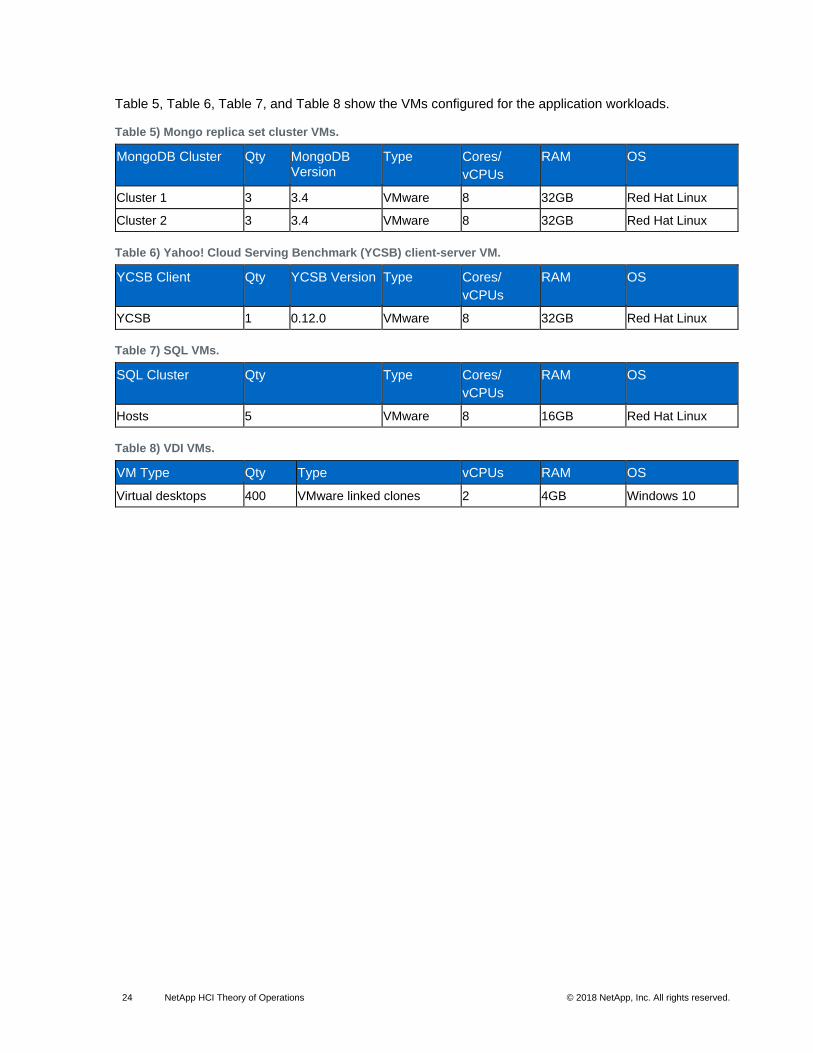
Table 5, Table 6, Table 7, and Table 8 show the VMs configured for the application workloads.
Table 5) Mongo replica set cluster VMs.
MongoDB Cluster Qty MongoDB Version
Type Cores/
vCPUs
RAM OS
Cluster 1 3 3.4 VMware 8 32GB Red Hat Linux
Cluster 2 3 3.4 VMware 8 32GB Red Hat Linux
Table 6) Yahoo! Cloud Serving Benchmark (YCSB) client-server VM.
YCSB Client Qty YCSB Version Type Cores/
vCPUs
RAM OS
YCSB 1 0.12.0 VMware 8 32GB Red Hat Linux
Table 7) SQL VMs.
SQL Cluster Qty Type Cores/
vCPUs
RAM OS
Hosts 5 VMware 8 16GB Red Hat Linux
Table 8) VDI VMs.
VM Type Qty Type vCPUs RAM OS
Virtual desktops 400 VMware linked clones 2 4GB Windows 10
25 NetApp HCI Theory of Operations © 2018 NetApp, Inc. All rights reserved.
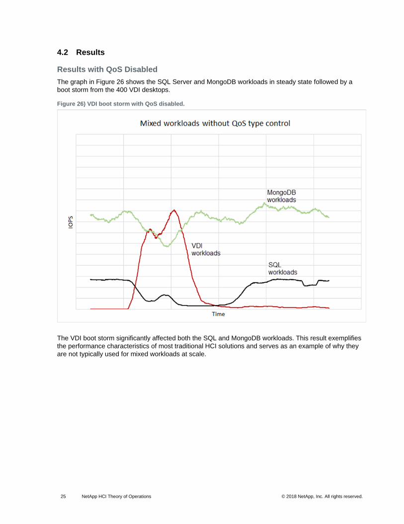
4.2 Results
Results with QoS Disabled
The graph in Figure 26 shows the SQL Server and MongoDB workloads in steady state followed by a
boot storm from the 400 VDI desktops.
Figure 26) VDI boot storm with QoS disabled.
The VDI boot storm significantly affected both the SQL and MongoDB workloads. This result exemplifies
the performance characteristics of most traditional HCI solutions and serves as an example of why they
are not typically used for mixed workloads at scale.

26 NetApp HCI Theory of Operations © 2018 NetApp, Inc. All rights reserved.
Results with QoS Enabled
The graph in Figure 27 shows the same workload, this time with QoS enabled.
Figure 27) VDI boot storm with QoS enabled.
The VDI boot storm had no impact on the SQL and MongoDB workloads on the system. This example
shows the strength of the QoS capabilities of the platform. QoS controls enable true mixed workload
applications for NetApp HCI.
More detailed information for the mixed workload testing can be found in TR-4632: NetApp HCI QoS and
Mixed Workloads.
5 Extending NetApp HCI
5.1 NetApp ONTAP Select
The SolidFire platform provides an enterprise-grade scalable architecture for NetApp HCI. However,
SolidFire is a block-only solution. NetApp ONTAP® Select 9.3 or higher can be installed by NDE to
provide a rich set of file services to the NetApp HCI platform.
ONTAP Select can be deployed at system setup as an optional component by the NDE or as a customer
installed feature after system installation.

27 NetApp HCI Theory of Operations © 2018 NetApp, Inc. All rights reserved.
Figure 28) Data Fabric—ONTAP Select.
For more information about configuring ONTAP Select for NetApp HCI systems, see TR-4669: HCI File
Services Powered by ONTAP.
Figure 29) ONTAP Select on HCI.
5.2 NetApp SnapMirror
The release of Element OS version 10.1 and NetApp ONTAP 9.3 brings NetApp SnapMirror® support to
the NetApp HCI system. For the initial release, replication from HCI to FAS is supported, as is restore
from FAS to HCI. The primary use case is replication of HCI systems to FAS. SnapMirror relationships
are managed through the Element OS UI at initial release.
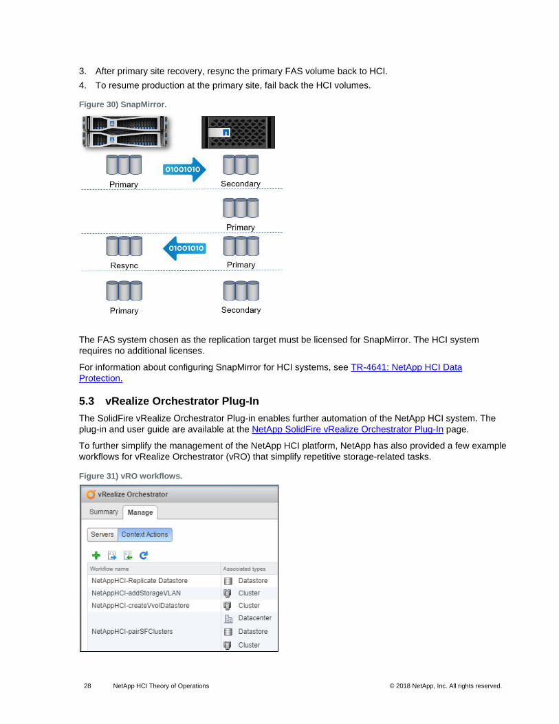
Replication and restoration of volumes are a four-step process:
1. Replicate HCI volumes to a FAS system licensed for SnapMirror.
2. In a disaster recovery scenario, promote the FAS target volume to primary and run production.
28 NetApp HCI Theory of Operations © 2018 NetApp, Inc. All rights reserved.
3. After primary site recovery, resync the primary FAS volume back to HCI.
4. To resume production at the primary site, fail back the HCI volumes.
Figure 30) SnapMirror.
The FAS system chosen as the replication target must be licensed for SnapMirror. The HCI system
requires no additional licenses.
For information about configuring SnapMirror for HCI systems, see TR-4641: NetApp HCI Data
Protection.
5.3 vRealize Orchestrator Plug-In
The SolidFire vRealize Orchestrator Plug-in enables further automation of the NetApp HCI system. The
plug-in and user guide are available at the NetApp SolidFire vRealize Orchestrator Plug-In page.
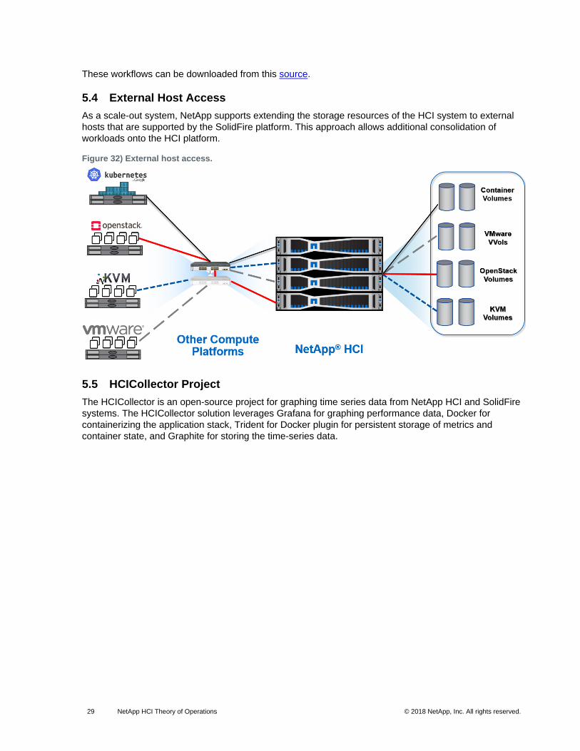
To further simplify the management of the NetApp HCI platform, NetApp has also provided a few example
workflows for vRealize Orchestrator (vRO) that simplify repetitive storage-related tasks.
Figure 31) vRO workflows.
29 NetApp HCI Theory of Operations © 2018 NetApp, Inc. All rights reserved.
These workflows can be downloaded from this source.
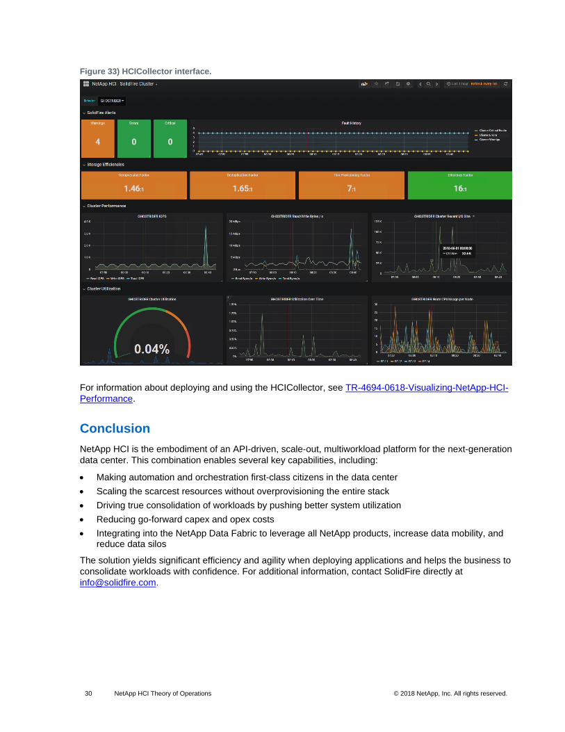
5.4 External Host Access
As a scale-out system, NetApp supports extending the storage resources of the HCI system to external
hosts that are supported by the SolidFire platform. This approach allows additional consolidation of
workloads onto the HCI platform.
Figure 32) External host access.
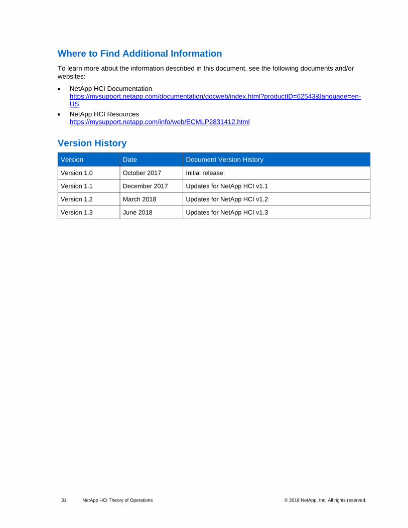
5.5 HCICollector Project
The HCICollector is an open-source project for graphing time series data from NetApp HCI and SolidFire
systems. The HCICollector solution leverages Grafana for graphing performance data, Docker for
containerizing the application stack, Trident for Docker plugin for persistent storage of metrics and
container state, and Graphite for storing the time-series data.
30 NetApp HCI Theory of Operations © 2018 NetApp, Inc. All rights reserved.
Figure 33) HCICollector interface.
For information about deploying and using the HCICollector, see TR-4694-0618-Visualizing-NetApp-HCI-
Performance.
Conclusion
NetApp HCI is the embodiment of an API-driven, scale-out, multiworkload platform for the next-generation
data center. This combination enables several key capabilities, including:
• Making automation and orchestration first-class citizens in the data center
• Scaling the scarcest resources without overprovisioning the entire stack
• Driving true consolidation of workloads by pushing better system utilization
• Reducing go-forward capex and opex costs
• Integrating into the NetApp Data Fabric to leverage all NetApp products, increase data mobility, and reduce data silos
The solution yields significant efficiency and agility when deploying applications and helps the business to
consolidate workloads with confidence. For additional information, contact SolidFire directly at
31 NetApp HCI Theory of Operations © 2018 NetApp, Inc. All rights reserved.
Where to Find Additional Information
To learn more about the information described in this document, see the following documents and/or
websites:
• NetApp HCI Documentation https://mysupport.netapp.com/documentation/docweb/index.html?productID=62543&language=en-US
• NetApp HCI Resources https://mysupport.netapp.com/info/web/ECMLP2831412.html
Version History
Version Date Document Version History
Version 1.0 October 2017 Initial release.
Version 1.1 December 2017 Updates for NetApp HCI v1.1
Version 1.2 March 2018 Updates for NetApp HCI v1.2
Version 1.3 June 2018 Updates for NetApp HCI v1.3

32 NetApp HCI Theory of Operations © 2018 NetApp, Inc. All rights reserved.
Refer to the Interoperability Matrix Tool (IMT) on the NetApp Support site to validate that the exact product and feature versions described in this document are supported for your specific environment. The NetApp IMT defines the product components and versions that can be used to construct configurations that are supported by NetApp. Specific results depend on each customer’s installation in accordance with published specifications.
Copyright Information
Copyright © 2018 NetApp, Inc. All rights reserved. Printed in the U.S. No part of this document covered by copyright may be reproduced in any form or by any means—graphic, electronic, or mechanical, including photocopying, recording, taping, or storage in an electronic retrieval system—without prior written permission of the copyright owner.
Software derived from copyrighted NetApp material is subject to the following license and disclaimer:
THIS SOFTWARE IS PROVIDED BY NETAPP “AS IS” AND WITHOUT ANY EXPRESS OR IMPLIED WARRANTIES, INCLUDING, BUT NOT LIMITED TO, THE IMPLIED WARRANTIES OF MERCHANTABILITY AND FITNESS FOR A PARTICULAR PURPOSE, WHICH ARE HEREBY DISCLAIMED. IN NO EVENT SHALL NETAPP BE LIABLE FOR ANY DIRECT, INDIRECT, INCIDENTAL, SPECIAL, EXEMPLARY, OR CONSEQUENTIAL DAMAGES (INCLUDING, BUT NOT LIMITED TO, PROCUREMENT OF SUBSTITUTE GOODS OR SERVICES; LOSS OF USE, DATA, OR PROFITS; OR BUSINESS INTERRUPTION) HOWEVER CAUSED AND ON ANY THEORY OF LIABILITY, WHETHER IN CONTRACT, STRICT LIABILITY, OR TORT (INCLUDING NEGLIGENCE OR OTHERWISE) ARISING IN ANY WAY OUT OF THE USE OF THIS SOFTWARE, EVEN IF ADVISED OF THE POSSIBILITY OF SUCH DAMAGE.
NetApp reserves the right to change any products described herein at any time, and without notice. NetApp assumes no responsibility or liability arising from the use of products described herein, except as expressly agreed to in writing by NetApp. The use or purchase of this product does not convey a license under any patent rights, trademark rights, or any other intellectual property rights of NetApp.
The product described in this manual may be protected by one or more U.S. patents, foreign patents, or pending applications.
RESTRICTED RIGHTS LEGEND: Use, duplication, or disclosure by the government is subject to restrictions as set forth in subparagraph (c)(1)(ii) of the Rights in Technical Data and Computer Software clause at DFARS 252.277-7103 (October 1988) and FAR 52-227-19 (June 1987).
Trademark Information
NETAPP, the NETAPP logo, and the marks listed at http://www.netapp.com/TM are trademarks of NetApp, Inc. Other company and product names may be trademarks of their respective owners.