hazards and risk assessment - major projects
TRANSCRIPT

Appendix B
Hazards and Risk Assessment


Prepared by: Karin Nilsson
4 November 2014
Prepared for: URS Australia Limited Document Number: URS\26-B388 Revision 0
PO Box 1497 Lane Cove NSW 2066
Telephone: [02] 9427 7851 Email: [email protected]
www.planager.com.au
HAZARD AND RISK ANALYSIS OF THE
PROPOSED CALTEX KURNELL
REFINERY DEMOLITION WORKS

C:\URS\26-B388\PHA Caltex Kurnell Demolition Project Rev 0 FINAL (2).Doc Revision 0 24 November, 2014 Hazard And Risk Analysis Of The Proposed Caltex Kurnell Refinery Demolition Works
Acknowledgment
The author would like to thank Dr Jos Kusters (Caltex) and Rachel O’Hara (URS Australia) for their assistance in preparing this report.
Disclaimer
This report was prepared by Planager Pty Ltd (Planager) as an account of work for URS Australia Pty Ltd. The material in it reflects Planager's best judgement in the light of the information available to it at the time of preparation. However, as Planager cannot control the conditions under which this report may be used, Planager and its related corporations will not be responsible for damages of any nature resulting from use of or reliance upon this report. Planager's responsibility for advice given is subject to the terms of engagement with URS Australia Pty Ltd.
Hazard and Risk Analysis of the Proposed Caltex
Kurnell Refinery Demolition Works
Rev Date Description Prepared By Reviewed By Authorised By
0 4/11/2014 Final Report Karin Nilsson Anne Lewis Karin Nilsson

C:\URS\26-B388\PHA Caltex Kurnell Demolition Project Rev 0 FINAL (2).Doc Revision 0 24 November, 2014 Hazard And Risk Analysis Of The Proposed Caltex Kurnell Refinery Demolition Works
CONTENTS EXECUTIVE SUMMARY ............................................................................................ I
GLOSSARY ........................................................................................................... IV
1 INTRODUCTION .............................................................................................. 5
1.1 Background...................................................................................... 5
1.2 Scope and Aim of the Demolition Works....................................... 6
1.3 Scope and Aim of the Hazard and Risk Assessment ................... 6
2 SITE AND PROJECT DESCRIPTION ................................................................... 8
2.1 Project Location .............................................................................. 8
2.2 Site Operations ................................................................................ 8
2.3 Demolition Works .......................................................................... 10
3 STUDY METHODOLOGY ................................................................................ 13
3.1 Hazard Identification ..................................................................... 13
3.2 Risk Analysis ................................................................................. 14
3.3 Risk Reduction and Comparison with Risk Tolerability Criteria 17
3.3.1 Qualitative Risk Assessment ........................................................... 17
3.3.2 Quantitative Risk Assessment ......................................................... 18
A. Individual Risk of Fatality ...................................................................................................... 18
B. Individual Risk of Injury ......................................................................................................... 18
C. Societal Risk of Fatality .......................................................................................................... 19
D. Risk of Property Damage and Accidental Propagation ............................................................. 19
E. Biophysical Risk .................................................................................................................... 20
4 HAZARD IDENTIFICATION AND CONTROLS ...................................................... 21
4.1 Hazardous Incident Scenarios ..................................................... 21
4.2 Detailed Consideration of All Hazards and Associated Controls .. ........................................................................................................ 33
4.2.1 Process Safety Related Hazards ..................................................... 33

C:\URS\26-B388\PHA Caltex Kurnell Demolition Project Rev 0 FINAL (2).Doc Revision 0 24 November, 2014 Hazard And Risk Analysis Of The Proposed Caltex Kurnell Refinery Demolition Works
A. Damage to Plant and Equipment or Cutting into Live Pipes...................................................... 33
B. Introduction of Ignition Sources into a Hazardous Area ........................................................... 34
4.2.2 General Health and Safety Related Hazards ................................... 34
A. Crushing, Impact, Falling, Drowning, Trapped or Subsidence .................................................. 34
B. Exposure to Hazardous Material or Dusts ................................................................................ 35
C. Damage to Overhead Power Lines........................................................................................... 35
4.2.3 Loss of Amenity to Workforce and Community ................................ 36
4.2.4 Other Risk to the Biophysical Environment...................................... 37
A. Incorrect Classification of Waste ............................................................................................. 37
B. Hazardous Interaction Between Public and Demolition Heavy Vehicle Traffic ......................... 37
C. Rain Event Re-contaminates Opened Pipework ....................................................................... 37
5 RISK ANALYSIS ........................................................................................... 38
5.1 Qualitative Risk Analysis .............................................................. 38
5.1.1 Risk Levels 1 to 5 ............................................................................ 38
5.1.2 Risk Level 6 ..................................................................................... 38
5.1.3 Risk Levels 7, 8, 9 and 10 ............................................................... 38
5.2 Quantitative Risk Analysis............................................................ 42
5.2.1 QRA Conducted for the Operating Terminal .................................... 42
A. Hazardous Release Scenarios .................................................................................................. 42
B. Consequence Assessment........................................................................................................ 42
C. Likelihood Estimation............................................................................................................. 42
D. Risk Assessment ..................................................................................................................... 43
5.2.2 Impact of Demolition Activities on Terminal QRA ............................ 43
A. Hazardous Release Scenarios .................................................................................................. 43
B. Consequence Assessment........................................................................................................ 43
C. Likelihood Estimation............................................................................................................. 44
D. Risk Assessment ..................................................................................................................... 46
6 DISCUSSIONS AND CONCLUSION ................................................................... 47
6.1 Demolition Hazards ....................................................................... 47

C:\URS\26-B388\PHA Caltex Kurnell Demolition Project Rev 0 FINAL (2).Doc Revision 0 24 November, 2014 Hazard And Risk Analysis Of The Proposed Caltex Kurnell Refinery Demolition Works
6.2 Overarching Control – Underlying Assumptions ....................... 47
6.3 Overall Conclusion ........................................................................ 49
6.4 Additional Recommended Actions and Notes of Caution ......... 49
7 REFERENCES .............................................................................................. 52
LIST OF FIGURES Figure 1 – Project Location ................................................................................. 9
Figure 2 – Proposed Demolition Works ............................................................ 11
Figure 3 - Chevron Integrated Risk Prioritization Matrix ................................... 15
LIST OF TABLES Table 1 – Hazard Identification Team ............................................................... 13
Table 2 – Likelihood Interpretation ................................................................... 16
Table 3 - Summary of Identified Hazards ......................................................... 21
Table 4 – Hazard Identification Word Diagram ................................................. 23
Table 5 – Risk Profile During Demolition .......................................................... 39
Table 6 – Risk Profile of Terminal .................................................................... 39

C:\URS\63-B388\PHA Caltex Kurnell Demolition Project Rev 0 FINAL (2).Doc Revision 0 24 November, 2014 i Hazard And Risk Analysis Of The Proposed Caltex Kurnell Refinery Demolition Works
EXECUTIVE SUMMARY E1 Introduction
Caltex Refineries (NSW) Pty Ltd (hereafter referred to as Caltex) announced in July 2012 that it would progress with converting the Kurnell Refinery (the Site) to a viable and sustainable terminal to receive and distribute refined petroleum product (the Project).
In accordance with the Department of Planning and Environment (DP&E) Director General’s Requirements for the Project, a Preliminary Hazard Analysis (PHA, Ref 1) was prepared for inclusion in the Environmental Impact Statement for SSD 5544. The PHA was prepared with reference to the State Environment Planning Policy (SEPP) No 33 – Hazardous and Offensive Development (Ref 2) and in accordance with the DP&I Hazardous Industry Planning Advisory Papers (HIPAP) Number 4 - Risk Criteria (Ref 3) and HIPAP Number 6 - Hazard Analysis (Ref 4).
The PHA for the Project concluded that the risk levels calculated for the proposed finished product terminal satisfy the criteria specified in HIPAP4 and that, when compared to the refinery operations, the off-site risk profile would be considerably reduced. The works to convert the refinery to a finished product terminal and the operation of the terminal (i.e. the Project) were approved as SSD 5544.
The works for which Caltex are seeking a modification to development consent SSD 5544 relate to the demolition, dismantling and removal of refinery process units, redundant tanks, redundant pipelines, redundant services and redundant buildings as well as associated minor civil works and waste management activities (the demolition works).
A hazards and risk assessment has been prepared by Planager Pty Ltd for the demolition works. This assessment has been completed in accordance with the DP&E Secretary’s Environmental Assessment Requirements (SEARs) for the demolition works, as follows:
Hazards and risks – including a Hazards in Demolition (HAZDEM) study that identified all significant demolition related hazards, and the assessment of the risks associated with these hazards. The analysis shall cover all phases of the proposed modification (i.e. demolition / removal of redundant assets and infrastructure), and include all components and stages (e.g. demolition of refinery process units, tanks, pipelines etc.). The demolition hazards and risk assessment shall particularly examine the following:
- The potential risk impacts from the proposed demolition works onto the existing simultaneous terminal operations;

C:\URS\63-B388\PHA Caltex Kurnell Demolition Project Rev 0 FINAL (2).Doc Revision 0 24 November, 2014 ii Hazard And Risk Analysis Of The Proposed Caltex Kurnell Refinery Demolition Works
- The potential for any of the identified demolition related risks to alter during the proposed works associated with the modification, individually or through interaction with existing operations, the offsite risk profile of the facility as assessed in the PHA report for SSD-554.
The results of the hazards and risk assessment for the demolition works are summarised in this report, which forms an appendix to the Statement of Environmental Effects for the modification application.
The report has been prepared with reference to SEPP No 33 and in accordance with the HIPAP4 - Risk Criteria and HIPAP6 - Hazard Analysis.
The demolition works comprise the demolition, dismantling or removal of the following principal components:
refinery process units and associated infrastructure; redundant tanks and associated infrastructure; redundant pipeways and underground pipelines; and redundant buildings and services.
As well as:
associated civil works with works outlined; waste management activities including concrete crushing; and returning the works areas to ground level.
Following the demolition works, the Site would operate as a finished product terminal as approved by SSD 5544.
E2 Results
The demolition works would be subject to rigorous scrutiny by Caltex and by the company contracted to carry out the demolition works. All parties would be responsible for safeguarding delivery and operation of the demolition works in a manner that minimises the risk to workers, contractors and the community.
The significant demolition related hazards have been identified. Their associated risk would be minimised through the implementation of a hierarchy of controls in accordance with the requirements under the NSW Work Health and Safety Act and associated Regulations, 2011 (WHS Regulations, Ref 5). The management of activities associated with the demolition work would ensure that the probability of an incident happening is minimised and that, should an incident occur, its consequences would be managed.
This hazard and risk assessment of the demolition works has found that the levels of risks to the biophysical environment and to the safety of the public, staff and contractors are reduced to So Far As Is Reasonably Practicable (SFAIRP) levels (as required by NSW WHS Regulations). This conclusion is based on:

C:\URS\63-B388\PHA Caltex Kurnell Demolition Project Rev 0 FINAL (2).Doc Revision 0 24 November, 2014 iii Hazard And Risk Analysis Of The Proposed Caltex Kurnell Refinery Demolition Works
Caltex continuing to implement a number of established processes for managing the Site;
the demolition contractors undertaking the demolition works in general accordance with Demolition Code of Practice (2013) and relevant Australian Standards; and
the recommendations formulated through the hazard and risk assessment process being implemented.
The present hazard and risk assessment has shown that the overall risk associated with the demolition works is low and does not introduce an excessive additional risk to the Site or to the community surrounding the Site.
Further, the hazard and risk assessment has shown that the risk profile, determined in the Preliminary Hazard Analysis for the Project (as reported in the Environmental Impact Assessment for the approved Project SSD 5544), remains valid during the demolition works. As such, the risk levels for the Site continue to satisfy the risk criteria specified in HIPAP 4 during demolition works.

C:\URS\63-B388\PHA Caltex Kurnell Demolition Project Rev 0 FINAL (2).Doc Revision 0 24 November, 2014 iv Hazard And Risk Analysis Of The Proposed Caltex Kurnell Refinery Demolition Works
GLOSSARY ALARP As Low As Reasonably Practicable
C Consequence
CHAIR Construction Hazard Assessment and Implication Review
DGRs Director-General’s Requirements
DPE Department of Planning and Environment
ESD Emergency Shutdown
HAZDEM Hazards in Demolition Study
HAZID Hazard Identification
HIPAP Hazardous Industry Planning Advisory Paper
JHA Job Hazard Analysis
JSA Job Safety Analysis
L Likelihood
mbgl metres below ground level
MHF Major Hazard Facility
OH&S Occupational Health and Safety
OPCO Operating Company
PHA Preliminary Hazard Analysis
PPE Personal Protective Equipment
PTW Permit to Work
SEARs Secretary’s Environmental Assessment Requirements
SEE Statement of Environment Effects
SFAIRP So Far As Is Reasonable Practicable
SSD State Significant Development
SWMS Safe Work Method Statements
T&I Turnaround and Inspection

C:\URS\26-B388\PHA Caltex Kurnell Demolition Project Rev 0 FINAL (2).Doc Revision 0 24 November, 2014 5
Hazard And Risk Analysis Of The Proposed Caltex Kurnell Refinery Demolition Works
REPORT 1 INTRODUCTION
1.1 BACKGROUND
Caltex announced in July 2012 that it would progress with converting the Kurnell Refinery (the Site) to a viable and sustainable finished product terminal to receive and distribute refined petroleum product (the Project).
In accordance with the DP&E Director General’s Requirements for the Project, a Preliminary Hazard Analysis (PHA, Ref 1) was prepared for inclusion in the Environmental Impact Statement for SSD 5544. The PHA was prepared with reference to the State Environment Planning Policy (SEPP) No 33 – Hazardous and Offensive Development (Ref 2) and in accordance with the DP&I Hazardous Industry Planning Advisory Papers (HIPAP) Number 4 - Risk Criteria (Ref 3) and HIPAP Number 6 - Hazard Analysis (Ref 4).
The PHA for the Project concluded that the risk levels calculated for the proposed finished product terminal satisfy the criteria specified in HIPAP4 and that, when compared to the refinery operations, the off-site risk profile would be considerably reduced.
The works to convert the refinery to a finished product terminal (i.e. the Project) were approved as SSD 5544 in January 2014.
The works for which Caltex are seeking a modification to development consent SSD 5544 relate to the demolition, dismantling and removal of refinery process units, redundant tanks, redundant pipelines, redundant services and redundant buildings as well as associated minor civil works and waste management activities (the demolition works).
A hazards and risk assessment has been prepared by Planager Pty Ltd for the demolition works. This assessment has been completed in accordance with the DP&E Secretary’s Environmental Assessment Requirements (SEARs) for the demolition works. For the Hazards and Risks assessment the SEARs request:
Hazards and risks – including a Hazards in Demolition (HAZDEM) study that identified all significant demolition related hazards, and the assessment of the risks associated with these hazards. The analysis shall cover all phases of the proposed modification (i.e. demolition / removal of redundant assets and infrastructure), and include all components and stages (e.g. demolition of refinery process units, tanks, pipelines etc.). The demolition hazards and risk assessment shall particularly examine the following:

C:\URS\26-B388\PHA Caltex Kurnell Demolition Project Rev 0 FINAL (2).Doc Revision 0 24 November, 2014 6
Hazard And Risk Analysis Of The Proposed Caltex Kurnell Refinery Demolition Works
- The potential risk impacts from the proposed demolition works onto the existing simultaneous terminal operations;
- The potential for any of the identified demolition related risks to alter during the proposed works associated with the modification, individually or through interaction with existing operations, the offsite risk profile of the facility as assessed in the PHA report for SSD-554.
The results of the hazards and risk assessment for the demolition works are summarised in this report which is appended to the Statement of Environmental Effects for the modification application.
The assessment has been prepared with reference to the SEPP No 33, and HIPAPs Numbers 4 (Risk Criteria, Ref 3) and 6 (Hazard Analysis, Ref 4).
1.2 SCOPE AND AIM OF THE DEMOLITION WORKS
The demolition works comprise the demolition, dismantling or removal of the following principal components:
refinery process units and associated infrastructure; redundant tanks and associated infrastructure; redundant pipeways and underground pipelines; and redundant buildings and services.
As well as:
associated civil works with works outlined; waste management activities including concrete crushing; and returning the works areas to ground level.
Following the demolition works, the Site would operate as a finished product terminal. The demolition works would support the operation of Site as a finished product import terminal, as approved by SSD 5544.
The Site would not be remediated as part of the demolition works.
1.3 SCOPE AND AIM OF THE HAZARD AND RISK ASSESSMENT
This hazard and risk assessment identifies and assesses hazards and risks associated with the following aspects of the demolition works:
demolition of process plant, equipment, pipelines and buildings; removal of demolished material; storage on site prior to disposal off-site; loading onto trucks; and transport off-site.
In line with the requirements in the SEARs, this hazards and risks assessment assesses the potential for demolition activities to:

C:\URS\26-B388\PHA Caltex Kurnell Demolition Project Rev 0 FINAL (2).Doc Revision 0 24 November, 2014 7
Hazard And Risk Analysis Of The Proposed Caltex Kurnell Refinery Demolition Works
impact on the tanks, interconnecting pipes and pipelines; impact the existing simultaneous terminal operations; and alter the offsite risk profile of the facility as assessed in the PHA for the
terminal (Ref 1) during the demolition works, both individually or through interaction with the terminal operation.
As per the methodology (Ref 4), the assessment focusses on potential high consequence – low likelihood incidents.
The following risks are assessed as part of this assessment:
risk from flammable material; environmental risk from spills; health and safety risks to staff and to contractors; and health and safety risk to the community.
The following activities are outside of the scope of the analysis as they do not form part of the demolition works:
Shutdown of process plant, pipes, conduits and tanks; and Decommissioning, cleaning and purging of all units.
The aim of the hazard and risk assessment is to:
provide an assessment of the hazards and risks associated with the demolition works;
determine the incremental change (increase or decrease) in the risk levels associated with the operating terminal during demolition activities;
evaluate the resulting risk levels against So Far As Is Reasonably Practicable (SFAIRP) principles in accordance with the WHS Regulations (Ref 5); and
assess the potential for any of the identified demolition related hazards and risks to alter the offsite risk profile of the facility, as assessed in the PHA for the terminal (Ref 1) during the demolition works, individually or through interaction with the terminal operation.
The risk associated with the demolition works is assessed qualitatively using the Caltex risk assessment process and risk matrix. The incremental impact on the off-site risk profile, as determined in the PHA for the terminal (Ref 1), is assessed quantitatively.
Note that the aim of this assessment is to inform the SEE for the demolition works. This assessment does not constitute a task based hazards and risk assessment and does not replace any of the hazard identification or risk assessment activities normally expected to be carried out by the demolition contractor in compliance with the legislative requirements as a minimum.

C:\URS\26-B388\PHA Caltex Kurnell Demolition Project Rev 0 FINAL (2).Doc Revision 0 24 November, 2014 8
Hazard And Risk Analysis Of The Proposed Caltex Kurnell Refinery Demolition Works
2 SITE AND PROJECT DESCRIPTION 2.1 PROJECT LOCATION
The Kurnell Refinery is located on the Kurnell Peninsula within Sutherland Shire Local Government Area (LGA), approximately 15 km south of Sydney’s CBD, as shown Figure 1 below.
Land uses surrounding the Site are as follows:
to the east and south of the Site is the southern portion of the Kamay Botany Bay National Park;
to the north-west of the Site, is the village of Kurnell; to the west of the Site is Quibray Bay; and land to the south west has the following landuse zonings:
- General Industrial; - Light Industrial; - Special Industrial; and - Special development.
The Site is immediately to the south of the Kurnell Village and the Kurnell Village lies immediately to the south of Botany Bay.
The Kurnell Peninsula is serviced by Captain Cook Drive. Captain Cook Drive has one lane for the majority of its length, travelling in each direction and is the only route of access and egress from the peninsula.
2.2 SITE OPERATIONS When operating as a refinery, the Kurnell Refinery was the largest oil refinery in NSW and the second largest of the seven oil refineries in Australia, based on crude oil processing capacity. As approved in SSD 5544, the Site is currently being converted to a terminal. Refinery operations will cease in the fourth quarter of 2014.
Once the conversion works are complete, Caltex will only import finished products (gasoline, jet fuel, diesel and fuel oil) through the two fixed berths at the existing wharf and the additional sub berth located in Botany Bay. These products will be stored in existing and converted tanks. The Site will have a nominal maximum storage capacity of 925 megalitres (ML) of fuel products and by products.

C:\URS\26-B388\PHA Caltex Kurnell Demolition Project Rev 0 FINAL (2).Doc Revision 0 24 November, 2014 9
Hazard And Risk Analysis Of The Proposed Caltex Kurnell Refinery Demolition Works
Figure 1 – Project Location

C:\URS\26-B388\PHA Caltex Kurnell Demolition Project Rev 0 FINAL (2).Doc Revision 0 24 November, 2014 10
Hazard And Risk Analysis Of The Proposed Caltex Kurnell Refinery Demolition Works
2.3 DEMOLITION WORKS
A summary of demolition works is provided below. Chapter 4 in the SEE provides further details on these works.
The demolition works would involve the demolition, dismantling or removal of refinery process units, redundant tanks, redundant pipelines, redundant services and redundant buildings as well as associated minor civil works and waste management activities. These works are planned to commence in mid-2015 and be completed by the end of 2017. The areas proposed for demolition (the proposed modification area) are shown in Figure 2.
Major demolition activities are listed below:
Refinery Process Units and Associated Infrastructure - disconnection and removal of pipelines from the process units area; - removal of insulation, corrosion protection materials and other
building materials prior to demolition taking place; - demolition of the refinery process units by lowering to a level where
they can be more easily cut up using heavy machinery; - intermediate storage of demolished material within the demolition
works area, as required prior to disposal, recycling or divestment; - removal of the foundations and slabs below the process units; and - removal of redundant cabling and some underground services
including the Oily Water Sewer from the area beneath the refinery process units.
These demolition works would require excavation work which may extend down to 2 metres below ground level (mbgl).
Tanks and Associated Infrastructure - disconnection and removal of a number of tanks and vessels from
both the eastern and western tank areas; - demolition of the tanks using heavy machinery to cut them up; - intermediate storage of the demolished material within the demolition
works area, prior to disposal or recycling; and - removal of redundant infrastructure associated with the tanks (such
as water draw equipment and pipelines). These demolition works may require excavation work which may extend down to 1 mbgl. The bunds associated with the demolished tanks would remain intact and in situ. Bund drainage would be by manual drain valve actuation.

C:\URS\26-B388\PHA Caltex Kurnell Demolition Project Rev 0 FINAL (2).Doc Revision 0 24 November, 2014 11
Hazard And Risk Analysis Of The Proposed Caltex Kurnell Refinery Demolition Works
Figure 2 – Proposed Demolition Works

C:\URS\26-B388\PHA Caltex Kurnell Demolition Project Rev 0 FINAL (2).Doc Revision 0 24 November, 2014 12
Hazard And Risk Analysis Of The Proposed Caltex Kurnell Refinery Demolition Works
Pipelines: the demolition work would also include the removal of seven underground pipelines, as follows: - the cooling water outlet line running from the refinery through the
Western right-of-way; - two cooling water intake lines running through the Eastern right-of-
way; - three redundant product lines running through the Eastern right-of-
way; and - the Continental Carbon pipeline running south from the Site.
The depth of excavation required for the removal of pipelines would be approximately 2 mbgl.
Interconnecting pipes: some pipes within the refinery process area would also need to be removed.
Buildings: - the demolition and removal of a number of redundant buildings on
Site related to the operation of the refinery; - demolition would be undertaken using heavy machinery such as
bulldozers and hydraulic excavators; - intermediate storage of the demolished material within the demolition
works area prior to disposal or recycling; and - removal of foundations and services associated with the redundant
buildings. These demolition works may require excavation work which may extend down to 1 mbgl.
Services: Removal of redundant cabling and underground services from within the refinery process area and buildings across the Site. These services would include: - connection points and underground pipes to the Oily Water Sewer
beneath the refinery process units; and - redundant sewer lines and cabling from redundant buildings that
included amenities.

C:\URS\26-B388\PHA Caltex Kurnell Demolition Project Rev 0 FINAL (2).Doc Revision 0 24 November, 2014 13
Hazard And Risk Analysis Of The Proposed Caltex Kurnell Refinery Demolition Works
3 STUDY METHODOLOGY The methodology for the hazards and risk assessments is well established in Australia. This assessment has been carried as per the Department of Planning’s HIPAP No 4 (Risk Criteria for Land Use Planning, Ref 3) and HIPAP No 6 (Guidelines for Hazard Analysis, Ref 4).
3.1 HAZARD IDENTIFICATION
The hazard identification process includes a review of potential hazards associated with demolition activities. It includes a comprehensive identification of possible causes of potential incidents and their consequences to public safety and the biophysical environment. It also outlines the proposed operational and organisational safety controls required to mitigate the likelihood of hazardous events occurring.
This process involved a two-day workshop where relevant data and information was reviewed and discussed in a multi-disciplinary team environment to highlight specific areas of potential concern and points of discussion. The team involved in the hazard identification workshop is listed in Table 1 below.
Table 1 – Hazard Identification Team
Name Title and Company Day 1 Day 2
Jos Kusters HSE Technical Superintendent for Decommissioning and Demolition, Caltex X
Rick Rech Demolition HSE Consultant X X
Clinton Dick Demolition Operations Engineer X
Craig Collard Demolition Project Manager, Caltex X X
Steve Whitwell Project Coordinator, Caltex X X
Alex Mann EHS Specialist, Caltex X X
Nicole Brewer Environment, URS Australia X X
Rachel O'Hara Environment, URS Australia X X
Karin Nilsson CHAIR Leader, Planager X X
Anne Lewis Risk management specialist and minute taker, Planager X X
During the hazard identification workshop, a preliminary hazard identification (HAZID) word diagram was prepared. This word diagram is provided in Section 4.

C:\URS\26-B388\PHA Caltex Kurnell Demolition Project Rev 0 FINAL (2).Doc Revision 0 24 November, 2014 14
Hazard And Risk Analysis Of The Proposed Caltex Kurnell Refinery Demolition Works
The HAZDEM methodology employed the Construction Hazard Assessment and Implication Review (CHAIR) safety in design tool (Ref 6), developed by NSW WorkCover.
The aim of the workshop was to identify and assess hazards and risks during construction and demolition activities. CHAIR is usually performed in three stages, with Stages 1 and 2 being relevant for the early design phase and Stage 3 generally being run later during the project phase. Hence, the hazard identification methodology for the demolition works used a combination of CHAIR Stages 1 and 2.
The review takes into account both random and systematic errors, and gives emphasis not only to technical requirements, but also to the management of the safety activities and the required competence of people involved.
3.2 RISK ANALYSIS
The risk associated with each incident scenario was evaluated in turn for:
the situation during the demolition works; and
the situation after the demolition works.
This evaluation used the Chevron Integrated Risk Prioritization Matrix, presented in Figure 3 below.
In performing the qualitative risk priority ranking, each cause-consequence scenario has been evaluated based on the severity of potential consequences and how probable it is that these consequences might fully develop (likelihood) with safeguards in place, according to:
Risk = Consequence x Frequency
The consequence ranking (1 to 6) and likelihood ranking (1 to 6) have been combined in the matrix to provide a risk priority ranking (1 to 10). Risk rankings are documented with “C” representing consequence, “L” representing likelihood, and “Risk” representing risk priority levels. While the Chevron risk matrix above is qualitative, a quantitative interpretation of the likelihood ranking must be made to allow assessment of the effect of the demolition hazards on the terminal risk profile, as determined in the PHA for the Project (Ref 1). The table below shows Planager’s quantitative interpretation of the likelihood indices and descriptions provided in the Chevron risk matrix. This interpretation is based on ISO31000 (Risk Management – Principles and guidelines, Ref 7), AS3931 (Risk analysis of technological systems – Application guide, Ref 8), discussion during the demolition workshops and risk engineering judgment.

Event can reasonably be expected to occur in life of
facility1 Likely 6 5 4 3 2 1
Conditions may allow the event to occur at the facility during its
lifetime, or the event has occurred within the Business
Unit
2 Occasional 7 6 5 4 3 2
Exceptional conditions may allowconsequences to occur within
the facility lifetime, or has occurred within the OPCO
3 Seldom 8 7 6 5 4 3Reasonable to expect that the
event will not occur at this facility. Has occurred several
times in the industry, but not in the OPCO
4 Unlikely 9 8 7 6 5 4
Has occurred once or twice within industry 5 Remote 10 9 8 7 6 5
Rare or unheard of 6 Rare 10 10 9 8 7 6
6 5 4 3 2 1
Incidental Minor Moderate Major Severe Catastrophic
Workforce: Minor injury such as a first-aid.
ANDPublic: No impact
Workforce: One or more injuries, not severe.
ORPublic: One or more minor injuries such as a first-aid.
Workforce: One or more severe injuries including permanently disabling
injuries.OR
Public: One or more injuries,not severe.
Workforce: (1-4) Fatalities OR
Public: One or more severe injuries including
permanently disabling injuries.
Workforce: Multiple fatalities(5-50)OR
Public: multiple fatalities (1-10)
Workforce: Multiple fatalities(>50)OR
Public: multiple fatalities (>10)
Workforce: Minor illness or effect with limited or no
impacts on ability to function and treatment is very limited
or not necessaryAND
Public: No impact
Workforce: Mild to moderateillness or effect with some treatment and/or functional impairment but is medically
managableOR
Public: Illness or adverse effect with limited or no
impacts on ability to function and medical treatment is limited or not necessary.
Workforce: Serious illness or severe adverse health
effect requiring a high level omedical treatment or
managementOR
Public: Illness or adverse effects with mild to moderate
functional impairment requring medical treatment.
Workforce (1-4): Serious illness or chronic exposure
resulting in fatality or significant life shortening
effectsOR
Public: Serious illness or severe adverse health effect
requiring a high level of medical treatment or
management.
Workforce (5-50): Serious illness or chronic exposure
resulting in fatality or significant life shortening
effectsOR
Public (1-10): Seriousillness or chronic exposure
resulting in fatality or significant life shortening
effects.
Workforce (>50): Serious illness or chronic exposure
resulting in fatality or significant life shortening
effectsOR
Public (>10): Serious illness or chronic exposure resulting
in fatality or significant life shortening effects.
Impacts such as localized or short term effects on habitat,
species or environmental media.
Impacts such as localized, long term degradation of
sensitive habitat or widespread, short-term
impacts to habitat, species orenvironmental media
Impacts such as localized but irreversible habitat loss or
widespread, long-term effects on habitat, species or
environmental media
Impacts such as significant, widespread and persistant changes in habitat, species
or environmental media (e.g. widespread habitat
degradation) .
Impacts such as persistent reduction in ecosystem function on a landscape
scale or significant disruptionof a sensitive species.
Loss of a significant portion of a valued species or loss ofeffective ecosystem function
on a landscape scale.
6 5 4 3 2 1
Incidental Minor Moderate Major Severe Catastrophic
Con
sequ
ence
D
escr
iptio
ns
Minimal damage. Negligible down time or asset loss.
Costs < $100,000.
Some asset loss, damage and/or downtime. Costs $100,000 to $1 Million.
Serious asset loss, damage to facility and/or downtime.
Costs of $1-10Million.
Major asset loss, damage to facility and/or downtime.
Cost >$10 Million but <$100 Million.
Severe asset loss or damageto facility. Significant
downtime, with appreciable economic impact. Cost >$100MM but <$1billion.
Total destruction or damage.Potential for permanent loss
of production. Costs >$1billion
Likelihood Indices
Assets(Facility Damage, Business
Interruption, Loss of Product)
Con
sequ
ence
Des
crip
tions
Environment
Consequence Indices
This matrix is endorsed for use across the Company. It is not a substitute for, and does not override any relevant legal obligations.
Under no circumstances should any part of this matrix be changed or modified, adapted or customized. This matrix identifies health, safety, environmental and asset risks and is to be used only by qualified and competent personnel.
Where applicable it is to be used within the Riskman2 structure and governance of an OE Risk Management Process. If applied outside of these Processes, it is also mandatory to manage identified intolerable risks and comply with the Risk Mitigation Closure Guidelines.
6 - Risk is tolerable if reasonable safeguards / management systems are confirmed to be in place and consistent with relevant requirements of the Risk Mitigation Closure Guidelines.
Con
sequ
ence
D
escr
iptio
ns &
Inde
x(w
ithou
t saf
egua
rds)
Safety
The above legend applies only to HES risks, where risk levels 1-6 are actionable and mandatory. For risks that may result in facility damage, business interruption, loss of product, the "Assets" category below should be used.
Asset risk reduction is at the discretion of management. Under no circumstances may a direct or indirect translation of Asset loss to HES consequences, or between any discrete categories of HES consequences be inferred.
ConsequenceIndices
Con
sequ
ence
Des
crip
tions
& In
dex
(with
out s
afeg
uard
s)
Health(Adverse effects resulting from chronic chemical or
physical exposures or exposure to biological
agents)
Decreasing Consequence/Impact
Chevron Integrated Risk Prioritization MatrixFor the Assessment of HES & Asset Risks from Event or Activity
Dec
reas
ing
Like
lihoo
dLikelihood
Descriptions
5 - Additional long term risk reduction required. If no further action can be reasonably taken, SBU management approval must be sought to continue the activity.Legend
Likelihood Descriptions & Index(with confirmed safeguards)
Legend applies to identified HES risks(see guidance documents for additional explanations) 1, 2 , 3, 4 - Short-term, interim risk reduction required. Long term risk reduction plan must be developed and implemented.
7, 8, 9, 10 - Manage risk. No further risk reduction required. Risk reduction at management / team discretion.
© 2005 Chevron Corporation

C:\URS\26-B388\PHA Caltex Kurnell Demolition Project Rev 0 FINAL (2).Doc Revision 0 24 November, 2014 16
Hazard And Risk Analysis Of The Proposed Caltex Kurnell Refinery Demolition Works
Table 2 – Likelihood Interpretation
Chevron Risk Matrix Planager Interpretation to Allow Comparison with Terminal Risk Profile (Ref 9)
Likelihood Descriptions Likelihood Indices
Likelihood Interpretation Quantitative Estimate
Consequences can reasonably be expected to occur in the life of the facility
1 Likely You may have heard of (or could well imagine) it happening at the plant since it started up
1 / 10 years
Conditions may allow the consequences to occur at the facility during its lifetime, or the event has occurred within the Business Unit
2 Occasional You may have heard of it happening at a similar plant somewhere in the world (if one plant life time is approximately 30-50 years, then this corresponds to 2 or 3 plant lives)
1 / 100 years
Exceptional conditions may allow the consequences to occur within facility lifetime, or the event has occurred within the Operating Company (OPCO)
3 Seldom You may not have heard of this happening at a similar plant but you can imagine that it could, in exceptional circumstances
1 / 1,000 years
Reasonable to expect that the consequences will not occur at this facility. Has occurred several times in the industry but not within the OPCO
4 Unlikely Most people have not heard of this event but it is not too difficult to imagine that it could happen somewhere in industry. Difficult to imagine that it would happen here.
1 / 10,000 years
Has occurred once or twice within industry
5 Remote You have probably not heard of this happening at any plants that you are aware of, but it is not an impossible event for industry, and you could imagine it happening elsewhere
1 / 100,000 years
Rare or unheard of 6 Rare Very slight probability, almost impossible / non credible (but not quite)
1 / 1,000,000 years

C:\URS\26-B388\PHA Caltex Kurnell Demolition Project Rev 0 FINAL (2).Doc Revision 0 24 November, 2014 17
Hazard And Risk Analysis Of The Proposed Caltex Kurnell Refinery Demolition Works
3.3 RISK REDUCTION AND COMPARISON WITH RISK TOLERABILITY CRITERIA
3.3.1 Qualitative Risk Assessment
The Chevron Integrated Risk Prioritization Matrix rankings are numbered and aligned with associated required actions for health, environment and safety risks, as listed below.
In accordance with the Chevron risk management rules, risk reduction requirements depend on the level of risk, as follows:
Risk levels 1, 2, 3, 4 – Short-term, interim risk reduction required. Long term risk reduction plan must be developed and implemented.
Risk level 5 – Additional long term risk reduction required. If no further action can be practicably taken, Strategic Business Unit (SBU) management approval must be sought to continue the activity.
Risk level 6 – Risk is tolerable if reasonable safeguards / management systems are confirmed to be in place and consistent with relevant Risk Reduction Procedure and Closure Guidelines.
Risk levels 7, 8, 9, 10 – No further risk reduction required if risk level is As Low As Reasonably Practicable (ALARP).
In the Caltex Safety Case regime, recommendations are provided for risk priority rankings 5 and above, as well as for events or conditions with low likelihood and high consequence that may require further risk evaluation. Recommendations are also provided for risks where they would eliminate or mitigate the potential causes and / or consequences predicted for the scenario.
The Integrated Risk Prioritization Matrix and associated required actions are used consistently by Caltex when developing the Safety Case for the refinery and associated facilities, as part of the requirements under the Major Hazard Facility requirements.
To ensure that the risk is managed in accordance with SFAIRP principles (in accordance with NSW Work Health and Safety Act and Regulations 2011), and to ensure that the risk profile for the Site during the demolition works does not exceed that of the terminal (as defined in the risk profile reported in the PHA for the Project (Ref 1)), the risk of each potential hazardous scenario has been minimised, regardless of it’s risk level. This is done through the assessment of existing (proposed) risk management controls and by recommending further controls where the risk is not deemed to follow SFAIRP principles. Particular attention has been paid to areas where potential existed for a risk profile of the Site to be affected by a hazardous scenario.

C:\URS\26-B388\PHA Caltex Kurnell Demolition Project Rev 0 FINAL (2).Doc Revision 0 24 November, 2014 18
Hazard And Risk Analysis Of The Proposed Caltex Kurnell Refinery Demolition Works
3.3.2 Quantitative Risk Assessment
The tolerability of the calculated risk is assessed by comparison with an appropriate risk target or criterion. The risk criteria used to make this assessment are specified in HIPAP4 (Ref 3). The risk criteria are detailed below.
A. Individual Risk of Fatality
The individual risk of fatality criteria described in HIPAP4 that are applicable to proposed hazardous developments are as follows:
Hospitals, schools, child-care facilities and old age housing development should not be exposed to individual fatality risk levels in excess of half in one million per year (0.5 x 10⁻⁶ per year).
Residential developments and places of continuous occupancy, such as hotels and tourist resorts, should not be exposed to individual fatality risk levels in excess of one in a million per year (1 x 10⁻⁶ per year).
Commercial developments, including offices, retail centres, warehouses with showrooms, restaurants and entertainment centres, should not be exposed to individual fatality risk levels in excess of five in a million per year (5 x 10⁻⁶ per year).
Sporting complexes and active open space areas should not be exposed to individual fatality risk levels in excess of ten in a million per year (10 x 10-6 per year).
Industrial sites should not be exposed to individual risk levels in excess of 50 in a million per year (50 x 10-6 per year) and, as a target, this risk level should be contained within the boundaries of the site where applicable.
These criteria were developed based on a principle that if the risk from a potentially hazardous installation is less than most risks being experienced by the community (e.g. voluntary risks, transportation risks), then that risk may be tolerated. This principle is consistent with the basis of risk criteria adopted by most authorities internationally.
The criterion for residential areas is demonstrably very low in relation to the background risk. It is considered conservative, as it assumed an individual is present and exposed for 24 hours per day, 365 days per year.
B. Individual Risk of Injury
HIPAP4 also outlines risk criteria for effects that may cause injury to people but will not necessarily cause fatality. The injury risk criteria are separated based on
C:\URS\26-B388\PHA Caltex Kurnell Demolition Project Rev 0 FINAL (2).Doc Revision 0 24 November, 2014 19
Hazard And Risk Analysis Of The Proposed Caltex Kurnell Refinery Demolition Works
the different effect types, i.e., heat radiation, explosion overpressure and toxic exposure. HIPAP 4 sets the following injury risk criteria:
Heat flux radiation at residential and sensitive use areas should not exceed 4.7 kW/m2 at a frequency of more than 50 x 10-6 per year.
Explosion overpressure at residential and sensitive use areas should not exceed 7 kPa at frequencies of more than 50 x 10-6 per year.
Toxic concentrations at residential and sensitive use areas should not exceed a level which would be seriously injurious to sensitive members of the community following a relatively short period of exposure at a maximum frequency of 10 x 10-6 per year.
C. Societal Risk of Fatality
The NSW DP&E has adopted indicative criteria to assess the off-site societal risk. The criteria take into account the fact that society is particularly intolerant of accidents, which although infrequent, have the potential to cause multiple fatalities. The criteria define three risk regions as follows (Ref 3):
Intolerable: above the “intolerable” line, the activity is considered undesirable, even if individual risk criteria are met.
ALARP (“as low as reasonable practicable”): within the ALARP region, the emphasis should be on reducing risk as far as possible towards the “negligible” line (i.e. ensuring that risks have been reduced to as low as reasonably practicable). Provided other quantitative and qualitative criteria of HIPAP4 are met, the risks from the activity may be considered tolerable within the ALARP region as long as all “reasonably practical” risk reduction measures have been implemented.
Negligible: below the “negligible” line the societal risk is not considered significant, provided other individual risk criteria are met.
D. Risk of Property Damage and Accidental Propagation
HIPAP4 sets risk criteria that reflect the potential for property damage and accident propagation. Assessment against the criteria provides an indication of the risk that an accident at the facility may cause damage to buildings and / or propagate to involve neighbouring industrial operations, causing further hazardous incidents, i.e. the so-called 'domino effect'. HIPAP4 sets the following criteria for risk of damage to property and accident propagation:
Heat flux radiation at neighbouring potentially hazardous installations, or at land zoned to accommodate such installations, should not exceed a risk of 50 x 10-6 per year for the 23 kW/m2 heat flux level.

C:\URS\26-B388\PHA Caltex Kurnell Demolition Project Rev 0 FINAL (2).Doc Revision 0 24 November, 2014 20
Hazard And Risk Analysis Of The Proposed Caltex Kurnell Refinery Demolition Works
Explosion overpressure at neighbouring potentially hazardous installations, at land zoned to accommodate such installations or at nearest public buildings should not exceed a risk of 50 x 10-6 per year for the 14 kPa explosion overpressure level.
E. Biophysical Risk
HIPAP 4 (Ref 3) outlines risk criteria addressing the risk from accidental releases to biophysical environment. The criteria focuses on the potential acute and chronic toxic impacts that an accidental release may have on whole systems and populations, rather than individual plants or animals. HIPAP4 expresses the criteria as follows:
Industrial developments should not be sited in proximity to sensitive natural environmental areas where the effects (consequences) of the more likely accidental emissions may threaten the long-term viability of the ecosystem or any species within it.
Industrial developments should not be sited in proximity to sensitive natural environmental areas where the likelihood (probability) of impacts that may threaten the long-term viability of the ecosystem or any species within it is not substantially lower than the background level of threat to the ecosystem.

C:\URS\26-B388\PHA Caltex Kurnell Demolition Project Rev 0 FINAL (2).Doc Revision 0 24 November, 2014 21
Hazard And Risk Analysis Of The Proposed Caltex Kurnell Refinery Demolition Works
4 HAZARD IDENTIFICATION AND CONTROLS
4.1 HAZARDOUS INCIDENT SCENARIOS
A list of the hazards associated with the demolition works is listed in Table 3 below.
A detailed Hazard Identification Word Diagram has been prepared for the demolition works and is presented in Table 4, in line with the requirements for hazard analysis (Ref 4). It includes initiating causes, consequences and proposed / existing safeguards to minimise the consequences or likelihood of an incident.
Further discussion and evaluation of safeguards is provided in Section 4.2.
This Hazard Identification Word Diagram draws from the potential incident scenarios identified during the hazard identification exercise that was undertaken (and detailed in Ref 9), as well as Planager experience.
A total of 20 hazards were identified, five (5) of these were associated with process safety related hazards; ten (10) with general health and safety hazards; and five (5) with loss of amenity and risks to the biophysical environment (not previously covered under other headings).
Table 3 - Summary of Identified Hazards
Hazard
Process Safety Related Hazards
Scenario 1: Damage to adjacent plant or equipment due to uncontrolled and/or unplanned falling of structure, object or crane collapse Scenario 2: Damage to live pipework during removal or inadvertent cutting into live pipe or pipeline
Scenario 3: Failure to isolate process equipment
Scenario 4: Damage to underground cables and/or oily water sewer
Scenario 5: Introduction of ignition sources in area classified as Hazardous Area
General Health and Safety Related Hazards
Scenario 6: Crushing or impact injuries
Scenario 7: Fall from heights
Scenario 8: Working over water with a potential for drowning
Scenario 9: Worker trapped (at end of wharf, at height etc.)
Scenario 10: Subsidence and collapse/fall into excavation
Scenario 11: Public and traffic hazardous interaction on public roads or footpath
Scenario 12: Loss of material in transit leading to traffic incident and potential injury

C:\URS\26-B388\PHA Caltex Kurnell Demolition Project Rev 0 FINAL (2).Doc Revision 0 24 November, 2014 22
Hazard And Risk Analysis Of The Proposed Caltex Kurnell Refinery Demolition Works
Hazard
Scenario 13: Exposure to airborne hazardous material, or skin contact with such material (heavy metals, asbestos etc.)
Scenario 14: Damage to overhead power lines
Scenario 15: Injury during diving operations
Loss of Amenity to Workforce and Community
Scenario 16: Discomfort from odour associated with removal and disposal of cooling water pipelines (smell – no health hazard) Scenario 17: Offensive odour and community complaints from mercaptan
Scenario 18: Noise generation (no health risk to community)
Other Risk to the Biophysical Environment Scenario 19: Incorrect classification of waste leading to contamination of trucks and potential delivery to wrong landfill location Scenario 20: Re-contamination of opened pipework
C:\URS\26-B388\PHA Caltex Kurnell Demolition Project Rev 0 FINAL (2).Doc Revision 0 24 November, 2014 23
Hazard And Risk Analysis Of The Proposed Caltex Kurnell Refinery Demolition Works
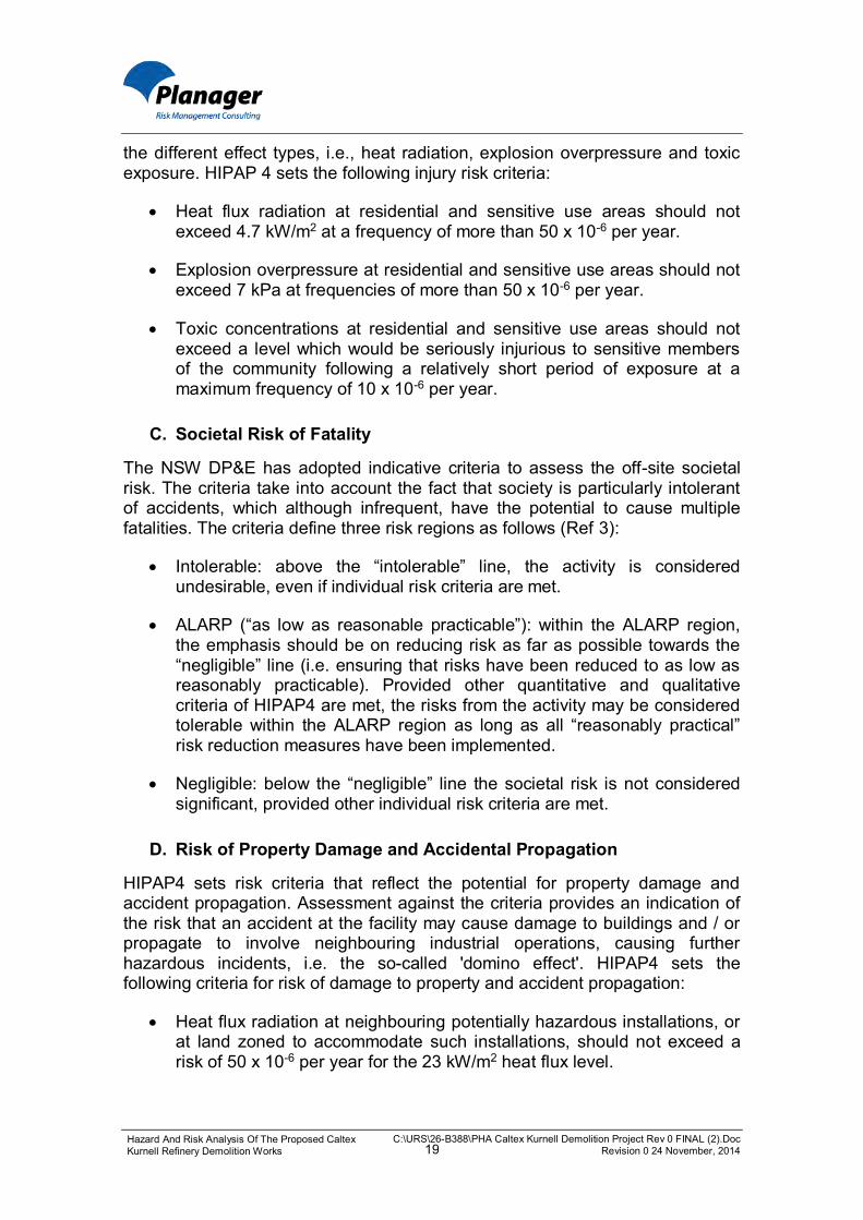
Table 4 – Hazard Identification Word Diagram
No Hazard Safeguards Residual Risk for Operating
Site
Residual Risk During
Demolition
Increase / Decrease of Risk Level Decrease Increase No change
Process Safety Related Hazards
1
Damage to adjacent (potentially in-service) tank, pipelines, utility, building or machinery due to: uncontrolled and/or
unplanned falling of structure/object;
crane collapse leads to process safety incident with potential for loss of containment, fire and explosion.
Prevention: Exclusion distances (workers/heavy machinery), access control. Separation distance between most tanks containing product and demolition activities. Caltex & contractor Permit to Work (PTW) systems. Safe Work Method Statements (SWMS) & Job Hazard Analysis (JHA) for all activities as per with Caltex Risk Management Framework (RMF). Top down deconstruction of tanks and buildings to maintain structural integrity and limit debris zone. Pre-start checks of vehicles and machinery. Specific for cranes: Crane operation and lifts to be carried out under Caltex Safe Work Standard Use of Lifting Equipment which sets stringent requirements for inspection of ground, site preparation and concrete slab / pavement thickness where crane outriggers are to be located. Lifting study to be certified/approved by competent person. Crane driver licence. Detection and communication: Supervision during all demolition activities; radio communication with control room. Protection: Bund to contain the spill should an adjacent tank containing product be damage. Leak detection & ESD (automatic and remote activated) in case of damage to pipelines. ESD of electrical system. Splashes outside bund, or leaks from unbunded pipes, captured in the secondary (site) containment and treatment. Closure of sluice gates as per ERP. Recommendations: 1. Demolition activities to be coordinated with terminal activities.
Where high risk demolition activities are to occur (e.g. where there is a risk of damage to terminal operations), an assessment needs to be completed in conjunction with terminal operations to formulate a hazard control plan specific to the high risk activity. This may include, but not limited to: a) timing the activity such that alternative product transfer options are available from other tanks / lines; b) changing the work methodology to lower the risk of equipment damage; or c)
Conseq.: 3 Likelihood:6
Risk: 8
Tank farm area: Conseq.: 3 Likelihood:5
Risk: 7
All other areas: Conseq.: 3 Likelihood:6
Risk: 8
The risk is marginally increased in the tank farm area during demolition activities due to the increased work with heavy machinery adjacent to
(potentially in-service) tanks. The risk in other areas would,
provided the recommendations are implemented, remain identical to the
risk for the operating terminal. Existing and recommended controls
considered to align with SFAIRP principles.
C:\URS\26-B388\PHA Caltex Kurnell Demolition Project Rev 0 FINAL (2).Doc Revision 0 24 November, 2014 24
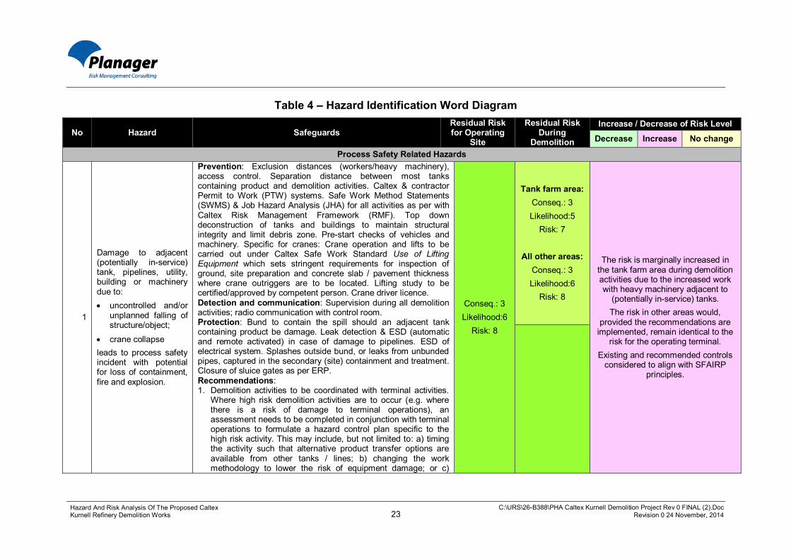
Hazard And Risk Analysis Of The Proposed Caltex Kurnell Refinery Demolition Works
No Hazard Safeguards Residual Risk for Operating
Site
Residual Risk During
Demolition
Increase / Decrease of Risk Level Decrease Increase No change
developing a product supply contingency plan. 2. Demolition works plan to include framework for considering the
demolition of individual tanks in shared tank farm areas (sequence activities for max space around in-service tanks).
3. Develop access control plan for the demolition area that reflects demolition operator having limited visibility when using heavy machinery / vehicles.
4. Determine requirements for evacuating buildings and blocking roadways during felling of tall structures.

C:\URS\26-B388\PHA Caltex Kurnell Demolition Project Rev 0 FINAL (2).Doc Revision 0 24 November, 2014 25
Hazard And Risk Analysis Of The Proposed Caltex Kurnell Refinery Demolition Works
No Hazard Safeguards Residual Risk for Operating
Site
Residual Risk During
Demolition
Increase / Decrease of Risk Level Decrease Increase No change
2
Damage to live pipework during removal of adjacent redundant pipe or pipeline, or inadvertent cutting into live pipework causing loss of containment of flammable liquid. Environmental damage if not contained and fire/explosion if ignition source present. Interruption to terminal and airport refuelling operations (if Banksmeadow jet fuel pipeline is damaged)
Prevention: Identification and marking of live and redundant lines. Open drains and vent lines on redundant pipework. PTW, SWMS, coordination (pre-start) meeting. Pipelines in rights of way: Pipelines to be unearthed prior to removal; cooling water lines are easily identified (vastly different diameters). Detection and communication: Gas testing. Manned activity allows manual ESD and communication with control room. Leak detection initiates ESD (tank farm and interconnecting pipes). Protection: In the case of work at tank farm and interconnecting pipes, Loss of Containment (LOC) will be contained on site in bunding and secondary (site) containment and treatment; ERP and fire water systems available; closure of sluice gates; oil spill response capability. Recommendation: As above regarding coordination of demolition activities and cessation of transfer operations during high risk demolition work. 5. Determine additional requirements for work on
interconnecting pipework adjacent to live pipes (e.g. cold cutting and controlled removal; protective barriers).
6. Increase surveillance (use spotters) for work adjacent to (within 1 meters of) live pipes / pipelines.
Conseq.: 3 Likelihood:6
Risk: 8
Conseq.: 3 Likelihood:6
Risk: 8
Provided recommendations are implemented, the risk remains the same during demolition activities
compared with that for an operating site (potentially in-service) pipes or
pipelines. Existing and recommended controls
align with SFAIRP principles.

C:\URS\26-B388\PHA Caltex Kurnell Demolition Project Rev 0 FINAL (2).Doc Revision 0 24 November, 2014 26
Hazard And Risk Analysis Of The Proposed Caltex Kurnell Refinery Demolition Works
No Hazard Safeguards Residual Risk for Operating
Site
Residual Risk During
Demolition
Increase / Decrease of Risk Level Decrease Increase No change
3
Failure to isolate process equipment (tank, piping etc.) results in LOC of flammable liquids, fire/explosion or exposure to high voltage electricity; environmental pollution and worker injury.
Prevention: Purging and cleaning of process equipment, tanks etc. prior to demolition works by competent, experienced Caltex personnel. Provision of positive isolation. Drains and vent lines opened on redundant pipework. Caltex SMP (minimum standard) used by contractor. Caltex reviews contractor SMP. PTW) including JHA. SWMS, communication and supervision. Pre-start review(s). Gas testing as part of PTW process. Independent verification of cleaning process carried out by demolition contractor, as per Demolition Code. Detection and communication: Supervision during all demolition activities; radio communication with control room. Protection: Bunding around tanks (able to contain 100% of contents). Leak detection with ESD system (automatic and remote activated) in case of damage to pipelines. Automatic shutdown of electrical system. LOCs outside the bund captured in secondary (site) containment and treatment. Closure of sluice gates as per ERP. Radio communication with control room. Recommendations: 7. Caltex to check contractor capability for independent
verification carried out by contractor (refer Demolition Code of Practice, Ref 10).
8. Investigate additional precautions required for floating roof tanks where pontoons may entrap flammable material which may not be detected during normal gas testing.
Conseq.: 3 Likelihood:5
Risk: 7
Conseq.: 3 Likelihood:5
Risk: 7
The risk also exists at an operating site (refinery or terminal) and may in
fact be marginally reduced during demolition activities due to the
systems in place. Proposed and recommended controls make for very
robust risk management of this potential hazard, in particular the
positive isolation and the independent verification (Caltex and contractor). SFAIRP principles are
adhered to.
C:\URS\26-B388\PHA Caltex Kurnell Demolition Project Rev 0 FINAL (2).Doc Revision 0 24 November, 2014 27
Hazard And Risk Analysis Of The Proposed Caltex Kurnell Refinery Demolition Works
No Hazard Safeguards Residual Risk for Operating
Site
Residual Risk During
Demolition
Increase / Decrease of Risk Level Decrease Increase No change
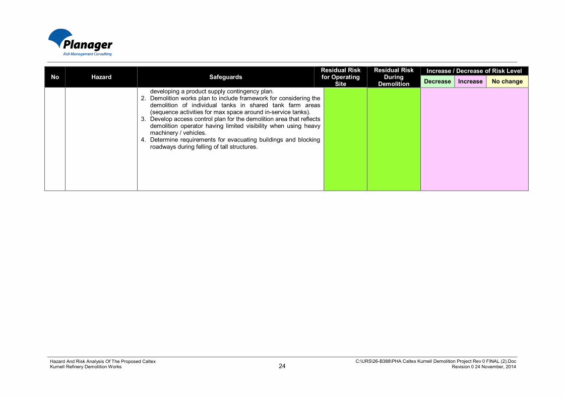
4
Damage to underground cables and/or oily water sewer in tank bunds and process area, due to compression/ slewing/ vibration, results in loss of containment of environmentally polluting material or short-circuiting of electrical connection
Prevention: Drawings show locations of cables and underground pipes. Procedure for work with heavy machinery including laying of protective plates. Use special tool (wanding tool) to locate electrical cables. Protection: Emergency Response Procedures (ERP) and Fire Water systems available. Closure of sluice gates as per ERP. Oil spill response capability.
Conseq.: 6 Likelihood:4
Risk: 9
Conseq.: 6 Likelihood:4
Risk: 9
Heavy machinery is used on the Site. No significant change to the risk
level. SFAIRP principles are maintained.
5
Introduction of ignition sources in area classified as Hazardous Area under Australian Standard
Prevention: Hazardous Area Classification and equipment rated in accordance with requirements. Plans and drawings show Hazardous Area zones.
Protection: ERP, fire water. Recommendation:
9. Review and update Hazardous Area classification drawings for demolition works, particularly in areas where demolition activities are to take place in parallel with an operating terminal. Particular attention should be paid to the fact that demolition contractors may not be well versed with the requirements for control of ignition sources at the Site.
Conseq.: 3 Likelihood:5
Risk: 7
Conseq.: 3 Likelihood:5
Risk: 7
The risk of unplanned / uncontrolled introduction of ignition sources into a Hazardous Area is well known and
understood by Caltex plant personnel and is relevant also for the operating
site. The safeguards are well established and the risk adheres to
SFAIRP principles.

C:\URS\26-B388\PHA Caltex Kurnell Demolition Project Rev 0 FINAL (2).Doc Revision 0 24 November, 2014 28
Hazard And Risk Analysis Of The Proposed Caltex Kurnell Refinery Demolition Works
No Hazard Safeguards Residual Risk for Operating
Site
Residual Risk During
Demolition
Increase / Decrease of Risk Level Decrease Increase No change
General Health and Safety Related Hazards
6
Crushing or impact injuries, e.g. from: vehicle toppling on
ramp; instability of sphere
or bullet during lay down;
crane toppling over; collapse of
uncontrolled movement of building;
truck driver crushed during loading operation
leading to injury or fatality of workforce.
Prevention: Induction, PTW, SWMS, JHA. Exclusion zone during demolition activities. Pre-start checklist for machinery. Use of ramps minimised and ramps designed and constructed by competent persons. Traffic management plan. Bullets are cut up in situ; spheres are collapsed and restricted from movement (chocked) prior to cutting. Lifting study for heavy lifting machinery (including cranes); competent person certifies/approves lifting study; high risk licenced crane workforce. Truck driver is supervised at all times on site; driver is required to move to a safe area. Caltex Operating Procedures and work methods, in relation to the integrity of access and egress points for heavy vehicles into bunds, set requirements for inspection by competent person prior to heavy vehicle entering the bund.
Protection: ERP, injury management. Recommendations: 10. Where ever possible, construct ramps away from
operational pipework.
Conseq.: 3 Likelihood:6
Risk: 8
Conseq.: 3 Likelihood:5
Risk: 7
There will be an increase in the risk of health and safety related hazards associated with the demolition works
due to the very nature of these activities. The hazards are well
known and understood by Caltex and contractors. The safeguards
established for these activities are heavily regulated and proceduralised. Detailed safeguards for each task will
be developed in due course to ensure adherence to generally
accepted SFAIRP principles for this type of industry.
7
Working at heights, e.g. to remove roofing material from building, results in fall and injury
Prevention: PTW and SWMS. Working at heights standards and codes of practice Protection: Working at heights training and rescue procedures. ERP.
Conseq.: 3 Likelihood:5
Risk: 7
Conseq.: 3 Likelihood:4
Risk: 6
As there will be more work at heights during demolition works the risk is considered to increase. Hazards
associated with work at heights are well known and understood by Caltex
and contractors. The safeguards established for these activities are
heavily regulated and proceduralised. Detailed safeguards for each task will
be developed in due course to ensure adherence to generally
accepted SFAIRP principles for this type of industry.

C:\URS\26-B388\PHA Caltex Kurnell Demolition Project Rev 0 FINAL (2).Doc Revision 0 24 November, 2014 29
Hazard And Risk Analysis Of The Proposed Caltex Kurnell Refinery Demolition Works
No Hazard Safeguards Residual Risk for Operating
Site
Residual Risk During
Demolition
Increase / Decrease of Risk Level Decrease Increase No change
8 Working over water results in drowning
Prevention: Wharf is fully hand railed. Provision of working platform with appropriate safety provisions. PTW and Safe Work Method Statement. Protection: Caltex procedures include wearing of self-inflating vests outside the hand railed area. ERP, injury management, first aid training.
Conseq.: 3 Likelihood:5
Risk: 7
Conseq.: 3 Likelihood:5
Risk: 7
There is no expected change to the risk level of this activity. The
safeguards are well established and adhere to SFAIRP principles.
9
Worker trapped in case of an external incident, e.g. at end of wharf, at height etc.
Prevention: Procedure for working at height or on wharf. Protection: Emergency response procedures including muster points and communications, rescue procedures.
Conseq.: 3 Likelihood:5
Risk: 7
Conseq.: 3 Likelihood:5
Risk: 7
No expected change in risk level. The safeguards are well established and the proposed controls adhere to
SFAIRP principles.
10
Subsidence and collapse/fall into excavation (of equipment, machinery, substation / building adjacent to right-of-way, person) due to sandy substrate with shallow angle of repose
Prevention: Exclusion zone and fencing. Excavation Code of Practice (2014). Procedure is to 'go wide or shore'. PTW (includes excavation hazards and controls) and SWMSs, JHA. Protection: ERP, injury management. Recommendation: 11. Minimise the risk of subsidence of the substation and
potentially of the nearby residential dwelling both of which are in very close proximity to the pipelines being removed within the eastern right-of-way.
Conseq.: 3 Likelihood:4
Risk: 6
Conseq.: 3 Likelihood:4
Risk: 6
There is no expected change to the risk level of this activity. The
safeguards are well established and the proposed controls adhere to
SFAIRP principles.
11
Public and traffic interaction on public roads and footpath causing vehicle or pedestrian accidents and injury
Prevention: Rights of way are fenced and gated. Traffic management plan (including traffic controllers). Traffic rules. Licenced HV drivers.
Conseq.: 4 Likelihood:4
Risk: 7
Conseq.: 4 Likelihood:4
Risk: 7
The potential for traffic incidents is in general well known and understood
by people in the vicinity of heavy vehicles (HVs). There will be an increase in the number of HVs
entering and leaving the Site during demolition activities and hence there will be an equal increase in risk. The
risk level will however remain unchanged. The safeguards are well
established and the proposed controls adhere to SFAIRP
principles.

C:\URS\26-B388\PHA Caltex Kurnell Demolition Project Rev 0 FINAL (2).Doc Revision 0 24 November, 2014 30
Hazard And Risk Analysis Of The Proposed Caltex Kurnell Refinery Demolition Works
No Hazard Safeguards Residual Risk for Operating
Site
Residual Risk During
Demolition
Increase / Decrease of Risk Level Decrease Increase No change
12
Loss of material in transit leading to traffic incident and potential injury
Prevention: Available truck checklist includes items related to keeping load secure. Trained and licenced truck drivers and loaders. Load sequencing (lighter gauge material loaded first). Penalties for inappropriate behaviour/activities is a deterrent. Protection: RMS guidelines for covering of loads. Weighbridge allows detection of an overloaded truck, allowing rectification prior to leaving the Site. Recommendations: 12. Implement Caltex inspection program to include truck
loading activities (e.g. use Tipper Truck Loading / Unloading Safety Inspection Checklist FORM 4.00.03.027)
Conseq.: 4 Likelihood: 5
Risk: 8
Conseq.: 4 Likelihood: 5
Risk: 8
There is no expected change to the risk level of this activity. The
safeguards are well established and the proposed controls adhere to
SFAIRP principles.
13
Exposure to airborne hazardous material or skin contact with such material during demolition activities, including to: Chromium or lead
from paint released during hot work of pipes;
Contaminated soil (asbestos, hydrocarbons, heavy metals
Asbestos (lagging etc.)
Prevention: Site is split into contamination management zones; a contamination management plan will be prepared as part of DEMP. Asbestos Containing Material Control Program, focussing on each zone. Handling procedures will be prepared. Training programs (awareness and induction) will be delivered to the workforce. Demolition contractor to have asbestos removal licence (Class A) and must comply with AS 2601-2001 and Safe Removal of Asbestos Code of Practice (2005). Managed disposal of asbestos containing material as per regulation. Testing for lead and chromium prior to hotwork - if lead/chromium is present paint will first be removed or material will be cold cut. Protection: Monitoring/observation/testing for contaminants during the demolition works. Dust control requirements (procedural and hardware) to be included in Safety Management Plan and Demolition Environment Management Plan.
Workforce and Community Conseq.: 3
Likelihood: 6 Risk: 8
Workforce Conseq.: 3 Likelihood:5
Risk: 7
Workforce The risk is currently present on Site,
but the risk to the workforce may increase due to the extent of the
demolition works. However the works will be staged, the safeguards are well established and the proposed
controls adhere to SFAIRP principles.
Community Conseq.: 3
Likelihood: 6 Risk: 8
Community The risk is present on the operating
Site. The safeguards are well established and the proposed
controls adhere to SFAIRP principles.

C:\URS\26-B388\PHA Caltex Kurnell Demolition Project Rev 0 FINAL (2).Doc Revision 0 24 November, 2014 31
Hazard And Risk Analysis Of The Proposed Caltex Kurnell Refinery Demolition Works
No Hazard Safeguards Residual Risk for Operating
Site
Residual Risk During
Demolition
Increase / Decrease of Risk Level Decrease Increase No change
14
Damage to overhead power lines leading to: - loss of power to community - damage to equipment - electrocution of demolition contractor
Prevention: Compliance with WorkCover Work Near Overhead Power Lines Code of Practice (2006). Signage. Caltex procedure for work near overhead power lines. PTW, SWMS. Tip-over axel trucks are not allowed on the Site (Caltex land, including rights-of-way). Protection: ERP, injury management. Recommendation: 13. Determine the requirements for isolation and/or installation
of protective barriers at the overhead power lines (in the rights-of-way), and notify the energy authorities prior to work being undertaken.
Conseq.: 3 Likelihood:5
Risk: 7
Conseq.: 3 Likelihood:5
Risk: 7
The risk of damage to the power lines is well known and understood by plant personnel and is relevant also for the operating site. With the
controls in place the level of risk should remain unchanged compared with that from the operating site or possibly slightly reduced. The risk
adheres to SFAIRP principles.
15 Injury during diving operations
Prevention: Training; use of buddy system; SOPs, limited depth of water.
Protection: Emergency response procedures and rescue plan.
Conseq.: 4 Likelihood: 5
Risk: 8
Conseq.: 4 Likelihood: 5
Risk: 8
There is no expected change to the risk level of this activity. The
safeguards are well established and the proposed controls adhere to
SFAIRP principles. Loss of Amenity to Workforce and Community
16
Discomfort (neighbours, workforce) from odour associated with removal and disposal of cooling water intake pipelines in eastern right of way (smell – no health hazard)
Prevention: Safe work method statements, PTW. Pipeline shutdown/removal schedule allows time for smell to dissipate. Cut-up cooling water pipework is to be removed from the area in a timely fashion.
- - This is not considered a major hazard and is not ranked in the
Caltex risk matrix
17
Offensive odour and community complaints if demolition rubble from the small mercaptan building contains contamination from mercaptan. Need to follow contaminated waste requirements.
Prevention: All mercaptan containing equipment/ canisters have already been removed. Building is to be emptied and aired prior to demolition. Protection: PPE used by workforce. Recommendations: 14. Determine chemical cleaning requirements to remove
contamination prior to removal. 15. Determine waste disposal requirements for mercaptan
building rubble.
Workforce Conseq.:6
Likelihood:4 Risk: 9
Workforce Conseq.:6
Likelihood:4 Risk: 9
The risk will decrease from that of the operating refinery. It will temporarily remain on-site during the demolition
activities, after which it will have been eliminated.
Community None
Community None
This is not considered a major hazard and is not ranked in the
Caltex risk matrix

C:\URS\26-B388\PHA Caltex Kurnell Demolition Project Rev 0 FINAL (2).Doc Revision 0 24 November, 2014 32
Hazard And Risk Analysis Of The Proposed Caltex Kurnell Refinery Demolition Works
No Hazard Safeguards Residual Risk for Operating
Site
Residual Risk During
Demolition
Increase / Decrease of Risk Level Decrease Increase No change
18
Community and workforce discomfort and generating complaints due to excessive noise generation. No health risk to community.
Prevention: Traffic management plan. Defined laydown and scrap processing areas located away from community. Scheduling of noisy demolition works during daylight hours. PPE for persons in immediate proximity, as determined in PTW and Safe Work Method Statements. Noise impact assessment as part of SEE. The HAZDEM workshop recommended that a noise assessment be undertaken in line with relevant NSW guidance to identify and mitigate potential noise impacts on the local community from the demolition works. This noise assessment has been completed and is provided in Appendix E of the SEE for the demolition works. Protection: Community consultation/ hotline for complaints. Recommendations: 16. High noise generating demolition works would be confined
to less sensitive times of the day and not outside the hours of 7.00 am to 6.00 pm Monday to Saturday.
Workforce Conseq.: 5
Likelihood: 3 Risk: 7
Workforce Conseq.: 5
Likelihood: 3 Risk: 7
Workforce Risk is well known and understood and will be assessed for each task
(SWMS, PTW, JHA). The safeguards will be established based on SFAIRP
principles.
Community Risk: none
Community Risk: none
Community This is not considered a major
hazard to the community and is not associated with any health hazards. As such it is not ranked in the Caltex
risk matrix.
Other Risk to the Biophysical Environment
19
Incorrect classification of waste leading to contamination of trucks and delivery to wrong landfill location.
Prevention: Waste is classified, streamed and stored in designated and signed locations in accordance with Waste Classification Guidelines (DECCW). Inspection of soil to identify potential contamination. Testing of potentially contaminated soil which is stored independently until results received. Disposal at appropriately licensed facilities. Protection: Lining of trucks and bins as required.
Conseq.:5 Likelihood: 4
Risk: 8
Conseq.:5 Likelihood: 4
Risk: 8
No expected change in risk level. The safeguards are well established and the proposed controls adhere to
SFAIRP principles.
20
Rain event re-contaminates opened pipework leading to environmental contamination in work area.
Prevention: Scheduling of work to minimise open pipework. Weather monitoring through, for example, the BOM website. Protection: de-contamination process prior to removal off site.
Conseq.:5 Likelihood:4
Risk:8
Conseq.:5 Likelihood:3
Risk:7
Some increase in risk due to increased activities associated with
opening up pipework and equipment. The risk is well known and
understood and the methods available ensures risk adheres to
SFAIRP principles

C:\URS\26-B388\PHA Caltex Kurnell Demolition Project Rev 0 FINAL (2).Doc Revision 0 24 November, 2014 33
Hazard And Risk Analysis Of The Proposed Caltex Kurnell Refinery Demolition Works
4.2 DETAILED CONSIDERATION OF ALL HAZARDS AND ASSOCIATED CONTROLS
The Hazard Identification Word Diagram in Table 4 above lists the control mechanisms for each identified hazard associated with the demolition works. Further details on these controls are provided below.
4.2.1 Process Safety Related Hazards
The following hazards and controls are identified for the demolition activities adjacent to operating facilities, plant and equipment (including interconnecting pipes and pipelines). Where the controls were not deemed as sufficient to reduce the risk level to SFAIRP, further safeguards have been recommended.
A. Damage to Plant and Equipment or Cutting into Live Pipes
(Scenarios 1, 2, 3 and 4)
Following damage to process plant, equipment and pipelines, or inadvertent cutting into live pipework, there is potential for loss of containment of process fluids which may result in a fire, an explosion, or a pollution event if the spill is not contained.
This hazard already exists at the Site and will continue to exist during the operation of the terminal, well after the demolition works have ceased.
The risk may be somewhat increased during demolition works within the tank farm area, compared with that for an operating site, due to the increased work with high structures and with heavy machinery adjacent to (potentially in-service) tanks. In other areas the risk is believed to remain as per the operating site.
A number of well-established controls apply to manage this hazard, including establishment of exclusion and separation distances; purging and cleaning processes (with independent verification); and isolation processes, including the requirement to prove positive isolation to process fluids. Further, the tank bunds will continue to provide protection should an adjacent (full) tank be damaged, allowing 100% of the tank’s contents to be contained within the bund.
Where damage occurs to interconnecting pipes on Site but outside of the bunds, the leak detection system, with automatic and remote activated Emergency Shut Down (ESD) system will limit the size of the spill to that between isolation valves. The secondary (site) containment and treatment system (including the ability to close sluice gates) will ensure that the spill remains on Site.
In the case of pipelines in the rights of way, these would be uncovered prior to removal to ensure identification.

C:\URS\26-B388\PHA Caltex Kurnell Demolition Project Rev 0 FINAL (2).Doc Revision 0 24 November, 2014 34
Hazard And Risk Analysis Of The Proposed Caltex Kurnell Refinery Demolition Works
As the management of this process safety hazard is key to ensuring that the risk profile of the Site remains unchanged from that of the terminal, as assessed in the PHA (Ref 1), a number of additional recommendations have been made (refer to Section 6). These recommendations include coordination between demolition and terminal activities; additional requirements for work on interconnecting pipework adjacent to live pipes; and increase surveillance for work adjacent to live pipes / pipelines.
B. Introduction of Ignition Sources into a Hazardous Area
(Scenario 5)
The hazard associated with an inadvertent and/or uncontrolled introduction of ignition sources into a Hazardous Area is well known and understood by Caltex plant personnel and is relevant for the refinery, the conversion works and ongoing operation of the terminal.
The controls available to manage such risks are well established and currently implemented by Caltex at the Site. These controls include Permit to Work (PTW) system, Safe Work Method Statements (SWMS) and Job Hazard Analysis (JHA) as well as Hazardous Area Classification drawings and equipment rated in accordance with zoning requirements that follow the Australian Standard for Hazardous Areas.
To maintain the level of rigour in the control of this hazard during the demolition works it is recommended that the Hazardous Area Classification drawings be updated to account for the demolition activities, particularly in areas where demolition activities are to take place in parallel with the operating terminal. Particular attention should be paid to the fact that demolition contractors may not be well versed with the requirements to control ignition sources at the Site.
4.2.2 General Health and Safety Related Hazards
A. Crushing, Impact, Falling, Drowning, Trapped or Subsidence
(Scenarios 6 to 10 and 15)
Demolition works are associated with a number of inherent health and safety risks due to the very nature of the activities likely to be carried out. Such activities include work at heights, work adjacent to heavy machinery and work with heavy loads. Caltex would work with the demolition contractor to ensure that these risks are well known and understood by the contractors licenced to carry out such activities and relevant Caltex employees.
The safeguards established for demolition activities are heavily regulated and proceduralised in Australia. Safeguards include training and induction; the use of standards and codes of practice, PTW systems, SWMS and JHA. The establishment of exclusion zones during demolition activities to separate people from machinery and overhanging objects and structures is critical.

C:\URS\26-B388\PHA Caltex Kurnell Demolition Project Rev 0 FINAL (2).Doc Revision 0 24 November, 2014 35
Hazard And Risk Analysis Of The Proposed Caltex Kurnell Refinery Demolition Works
Subsidence hazards are managed in accordance with the Excavation Code of Practice (2014, Ref 10).
Detailed safeguards would be developed prior to demolition works commencing to ensure adherence to SFAIRP principles for each task.
Further, a competent person would verify / inspect access ramps to bunds, ramps would be constructed away from operating pipework wherever possible; and the risk of subsidence of the substation and potentially also of the residential building in very close proximity to the right of way pipelines would be minimised.
B. Exposure to Hazardous Material or Dusts
Certain buildings and soils contain materials which could be harmful to humans if they are not managed appropriately. Potentially harmful material include asbestos (e.g. from old lagging), paints (containing heavy metals e.g. chromium, lead) and contaminated soil.
While this hazard is already present on the Site it is believed that it will be somewhat increased during demolition activities in contaminated areas or during works involving potentially harmful material.
Caltex has undertaken previous assessments of the Site and identified contaminated areas (Coffey, 2007). The Contamination Management Plan as part of the Demolition Environmental Management Plan (DEMP) would set up the framework for the management of contaminated soil during the demolition works. It would include procedures for monitoring soils as they are excavated, measures for handling and storing the contaminated soil (including loading and disposal), measures to avoid potential impacts on workforce and community, and general management requirements. The Contamination Management Plan would refer to the EPL for the Site, Contaminated Land Management Act 1997 and the NSW (2009) Waste Classification Guidelines and its Regulations (refer to Chapter 9 Soils, Groundwater and Contamination of the SEE). Caltex is committed to following all requirements provided in these documents. Such steps would include preparation of handling procedures and delivery of training programs. Further, the demolition contractor would have an asbestos removal licence (Class A) and their work must comply with AS 2601(The demolition of structures (Ref 11)) and Safe Removal of Asbestos Code of Practice (Ref 12).
C. Damage to Overhead Power Lines
Work in the right-of-ways would be in close proximity to overhead power lines. If the demolition works within the right of ways are not managed correctly, there is a risk that these power lines maybe damaged. Damage could lead to loss of power to the community, damage to equipment and electrocution of demolition personnel.
The Work Near Overhead Power Lines Code of Practice (Ref 13) provides the framework for establishing the controls during these activities. Further, Caltex

C:\URS\26-B388\PHA Caltex Kurnell Demolition Project Rev 0 FINAL (2).Doc Revision 0 24 November, 2014 36
Hazard And Risk Analysis Of The Proposed Caltex Kurnell Refinery Demolition Works
has established procedure for work near the overhead power lines, which include PTW, SWMS and the fact that tip-over axle trucks are not allowed on the main refinery/terminal site, land owned by Caltex, the rights-of-way or the Kurnell Wharf.
It is recommended that the requirements for isolation and/or installation of protective barriers at the overhead power lines (in the rights-of-way) be determined in consultation with energy authorities.
4.2.3 Loss of Amenity to Workforce and Community
(Scenarios 16, 17 and 18)
Both the community and the workforce may suffer a temporary reduction in amenity as a result of odour impacts associated with removal and disposal of cooling water intake pipelines from the eastern right of way, or during movement of demolition rubble from the small mercaptan building should it be contaminated with mercaptan. There may also be noise generated from the demolition activities carried out on Site which would be audible at certain residential receptors.
A Traffic Management Plan will be put in place to manage traffic generated during demolition activities. Further, defined laydown and scrap processing areas would be located away from community in the southern part of the Site and demolition works would be scheduled during daylight hours.
Controls to manage offensive odours include the use of SWMS and PTW; following the pipeline shutdown/removal schedule; removing cooling water intake pipework from the right of way in a timely fashion; and removing all mercaptan containing equipment/ canisters well ahead of demolition and the building being emptied and aired.
It is further recommended that chemical cleaning requirements to remove mercaptan contamination (from the mercaptan building) be determined prior to removal.
The risk to the community from the loss of amenity is very low as these events are not considered a major hazard and, as such, are not ranked in the Caltex risk matrix. There is some risk to the workforce from excessive noise and exposure to mercaptan.
Noise and traffic management is further discussed in Chapters 13 and 15 respectively of the SEE.

C:\URS\26-B388\PHA Caltex Kurnell Demolition Project Rev 0 FINAL (2).Doc Revision 0 24 November, 2014 37
Hazard And Risk Analysis Of The Proposed Caltex Kurnell Refinery Demolition Works
4.2.4 Other Risk to the Biophysical Environment
A. Incorrect Classification of Waste
(Scenario 19)
Incorrect classification of waste may lead to contamination of trucks and potential delivery of material to the wrong landfill location.
The Waste Classification Guidelines (Ref 14) sets the framework for managing potentially contaminated wastes. The key control includes the classification, screening and storage of wastes in designated and signed locations in accordance with these guidelines. Further, inspection and testing programs would be established, prior to disposal in appropriately licensed facilities.
B. Hazardous Interaction Between Public and Demolition Heavy Vehicle Traffic
(Scenarios 9 and 10)
The hazardous interaction of the public and traffic generated by the demolition works on public roads and footpaths may result in vehicle or pedestrian accidents and injury. Controls are well established in Australia and include following traffic rules, the use of licenced drivers and loaders, covering loads and the fact that inappropriate behaviour/activities are penalised (which acts as a deterrent).
Further site-specific controls include the rights of way remaining fenced and gated; the establishment of a Traffic Management Plan as part of the DEMP which includes traffic controls; and the use of checklist and processes (including load sequencing). In addition, trucks are required to use the weighbridge prior to leaving the Site. Trucks that are overloaded with material are identified at this point and are returned to Site to allow the issue to be rectified.
It is further recommended that the Caltex audit program be implemented to include truck loading activities.
C. Rain Event Re-contaminates Opened Pipework
Rain events may re-contaminate previously opened pipework leading to potential for environmental contamination in the demolition works area. This risk can be prevented by planning work to minimise open pipework, by covering open pipework and by monitoring the weather and managing the works accordingly.

C:\URS\26-B388\PHA Caltex Kurnell Demolition Project Rev 0 FINAL (2).Doc Revision 0 24 November, 2014 38
Hazard And Risk Analysis Of The Proposed Caltex Kurnell Refinery Demolition Works
5 RISK ANALYSIS
5.1 QUALITATIVE RISK ANALYSIS
As discussed above, the qualitative risk assessment has been prepared on the basis of the risk matrix and associated consequence and likelihood scoring tables in Section 3.2, and based on the hazardous incident identification exercise summarised in Table 4 above.
The risk profile of the Site during the demolition works is presented in Table 5. In comparison, the risk profile of the terminal is presented in Table 6. Note that, as per the risk matrix, a low number represents a high risk while a high number represents a low risk.
5.1.1 Risk Levels 1 to 5
No scenarios with risk levels 1 to 5 were identified for the operating terminal or for the terminal during the demolition works.
5.1.2 Risk Level 6
According to the risk criteria for risk level 6 scenarios (refer to Chevron’s risk matrix criteria detailed in Section 3.3.1): Risk is tolerable if reasonable safeguards / management systems are confirmed to be in place and consistent with relevant Risk Reduction Procedure and Closure Guidelines.
The following hazards were ranked as risk level 6 for the terminal during the proposed work:
Scenario 7: Working at heights Scenario 10: Subsidence and collapse/fall into excavation
The hazards associated with Scenarios 7 and 10 are typical for demolition activities and are well known and understood by plant personnel and demolition contractors. The safeguards established for these activities are heavily regulated and proceduralised. Detailed safeguards for each task would be developed in due course to ensure adherence to generally accepted SFAIRP principles for this type of industry and for these types of activities.
5.1.3 Risk Levels 7, 8, 9 and 10
According to the risk criteria for scenarios ranked with risk levels 7, 8, 9, and 10 (refer to Chevron’s risk matrix criteria detailed in Section 3.3.1): No further risk reduction required if risk level is As Low As Reasonably Practicable (ALARP).

C:\URS\26-B388\PHA Caltex Kurnell Demolition Project Rev 0 FINAL (2).Doc Revision 0 24 November, 2014 39
Hazard And Risk Analysis Of The Proposed Caltex Kurnell Refinery Demolition Works
Table 5 – Risk Profile During Demolition Table 6 – Risk Profile of Terminal

C:\URS\26-B388\PHA Caltex Kurnell Demolition Project Rev 0 FINAL (2).Doc Revision 0 24 November, 2014 40
Hazard And Risk Analysis Of The Proposed Caltex Kurnell Refinery Demolition Works
The majority of scenarios are ranked as risk levels 7 or 8, both for the operating terminal and for the terminal during the demolition works.
The list below shows the scenarios which are ranked as risk level 7 during the demolition works:
Scenario 1 (tank farms): Damage to adjacent plant or equipment due to uncontrolled and/or unplanned falling of structure, object or crane collapse (this scenario is ranked as risk level 8 for the operating terminal).
Scenario 3: Failure to isolate process equipment. Scenario 5: Introduction of ignition source in area classified as a
Hazardous Area. Scenario 6: Crushing or impact injuries (this scenario is ranked as risk
level 8 for the operating terminal). Scenario 8: Working over water results in drowning. Scenario 9: Worker trapped in case of an external incident. Scenario 11: Hazardous public and traffic interaction on public roads and
footpaths. Scenario 13 (workforce): Exposure to hazardous material or dust (this
scenario is ranked as risk level 8 for the operating terminal). Scenario 14: Damage to overhead power line. Scenario 18: Noise generation (no health risk to community). Scenario 20: Rain event re-contaminates opened pipework (this scenario
is ranked as risk level 8 for the operating terminal). The following hazards were ranked as risk level 8 during the demolition works:
Scenario 1 (non-tank farm areas): Damage to adjacent plant or equipment due to uncontrolled and/or unplanned falling of structure, object or crane collapse this scenario is ranked as risk level 8 for the operating terminal).
Scenario 2: Damage to live pipework during removal or inadvertent cutting into live pipe or pipeline.
Scenario 12: Loss of material in transit leading to traffic incident. Scenario 13 (community): Exposure to hazardous material or dust (this
scenario is not considered credible for the operating terminal). Scenario 15: Injury during diving operations. Scenario 19: Incorrect classification of waste.
The following scenarios were ranked as risk level 9:
Scenario 4: Damage to underground cables and/or oily water sewer. Scenario 17 (workforce): Offensive odour and community complaints
from mercaptan (this scenario is not considered credible for the operating terminal as the mercaptan would have been removed from the Site).
No scenarios were ranked as of level 10 as this hazard and risk assessment focussed on high consequence – low likelihood accidents.

C:\URS\26-B388\PHA Caltex Kurnell Demolition Project Rev 0 FINAL (2).Doc Revision 0 24 November, 2014 41
Hazard And Risk Analysis Of The Proposed Caltex Kurnell Refinery Demolition Works
Note that Scenario 16: Discomfort from odour associated with removal and disposal of cooling water intake pipelines, is not considered a major hazard and is not discussed further in this risk assessment.

C:\URS\26-B388\PHA Caltex Kurnell Demolition Project Rev 0 FINAL (2).Doc Revision 0 24 November, 2014 42
Hazard And Risk Analysis Of The Proposed Caltex Kurnell Refinery Demolition Works
5.2 QUANTITATIVE RISK ANALYSIS
5.2.1 QRA Conducted for the Operating Terminal
A quantitative risk analysis was conducted as part of the EIS for the new terminal and reported in the PHA, in Appendix C of the EIS (Ref 1).
A. Hazardous Release Scenarios
The PHA developed a number of hazardous LOC scenarios to represent the range of possible failures associated with each isolatable section of the terminal. These failure modes were represented as releases from selected hole sizes. The isolable sections were defined depending on a number of factors including:
Material; Process conditions (e.g. temperature and pressure); State (i.e. vapour or liquid); Inventory; Flow rate; and Utilisation (i.e. percentage of the time in use).
B. Consequence Assessment
The hazardous LOC scenarios in the PHA mostly relate to a loss of containment event of flammable or combustible liquids with a subsequent ignition and fire or explosion.
For each hazardous LOC scenario, consequence modelling was conducted as part of the PHA, for a range of hole sizes. The consequence modelling determined the area impacted by each consequence event. The consequence modelling in the PHA was conducted using the software package PHAST-RISK. The consequence impact distances for each effect type was assumed to depend on the following conditions:
Release conditions (temperature, pressure, hole size and duration); Release source (elevation, orientation); Chemical properties; and Atmospheric conditions (wind speed).
The frequency assessment used available historical failure rate data from a number of public sources, all relevant to an operating industrial site similar to the proposed terminal.
C. Likelihood Estimation
The failure rate data obtained from public sources was used in the QRA without modification. No specific characteristics, such as environmental factors, were identified that would require the failure data to be modified. For example, no

C:\URS\26-B388\PHA Caltex Kurnell Demolition Project Rev 0 FINAL (2).Doc Revision 0 24 November, 2014 43
Hazard And Risk Analysis Of The Proposed Caltex Kurnell Refinery Demolition Works
unusually harsh conditions are experienced at the Site that would cause failure modes, such as corrosion, to occur at significantly higher rates than those typical across industry. Additionally, in terminal operations, Caltex will continue to use its established integrity management processes, which are largely-based on industry standards. It is expected that these established processes will serve to maintain integrity management performance at a level that is at least equal to the performance reflected within the failure rate data used in the QRA model. Caltex also has established processes for corporate audits, insurance engineering surveys and external audits.
D. Risk Assessment
The PHA assessed the consequences and likelihoods of each hazardous LOC scenario in turn and then combined the individual scenario risks to generate the risk profile for the operating terminal. Both pool fires and vapour cloud explosions were considered.
The PHA was largely quantitative and determined a risk profile for the Project, using quantitative risk analysis (QRA). The risk profile for the terminal was shown to adhere to all risk criteria, as presented within the NSW Department of Planning’s guideline for risk criteria in landuse planning (HIPAP4, Ref 3).
5.2.2 Impact of Demolition Activities on Terminal QRA
A. Hazardous Release Scenarios
The Site operations would, during demolition activities, resemble closely those of the operating terminal. The difference would be the simultaneous demolition activities which have the potential to affect the terminal operation and hence it’s associated risk profile.
All of the hazardous LOC scenarios that were determined for the operating terminal, as defined in the PHA, would also be relevant for the Site during demolition phase. No additional LOC scenarios, which could affect the risk profile for the terminal, have been identified during the demolition phase, (note that the scenarios identified during demolition have a potential to trigger a LOC scenario).
B. Consequence Assessment
The consequence of each hazardous LOC scenario would remain unchanged. This is particularly so as the main process safety related controls would also remain active during demolition activities. For example, bunds and other methods of retaining a spill, detection and emergency shutdown systems to minimise the duration of the spill, and emergency response, including fire fighting capabilities, would remain active during the demolition phase as well as during the operation of the terminal.
C:\URS\26-B388\PHA Caltex Kurnell Demolition Project Rev 0 FINAL (2).Doc Revision 0 24 November, 2014 44
Hazard And Risk Analysis Of The Proposed Caltex Kurnell Refinery Demolition Works
C. Likelihood Estimation
It is the likelihood of the flammable event that requires further scrutiny, both from a point of view of the demolition activities affecting the likelihood of a LOC event and the probability of an ignition of a flammable or combustible release. A discussion as to the effect on the likelihood of the flammable events is provided below.
The PHA provided a quantitative estimate of the likelihood of a LOC of flammable of combustible material for each scenario, as follows:
Storage tanks: LOC frequency in the order of 10-3 per year per tank (for small leaks), to 10-4 per year per tank (for very large leaks) and 10-5 per year per tank (for rupture leaks);
Process piping and transfer pipes (such as the pipelines): LOC frequency in the order of 10-5 per meter per year (for small leaks), to 10-7 per meter per year (for rupture leaks);
Pumps: LOC frequency in the order of 10-3 to 10-5 per year per pump;
Flanges: LOC frequency in the order of 10-5 per year per flange; and
Valves: LOC frequency in the order of 10-5 to 10-6 per valve.
The initiating (trigger) events for each type of LOC scenario include impact events (including uncontrolled and/or unplanned falling of structure or object); failure during maintenance or repair (e.g. failure to isolate, or inadvertent cutting into live pipework); corrosion, failure to maintain; operating conditions being exceeded (e.g. overpressure, overflow) etc. The individual frequency of each one of these trigger events makes up the total likelihood for the LOC scenario.
Further, the PHA used a probability of ignition of 1% for small LOCs and up to 8% for very large LOCs. The ignition on an industrial facility such as the terminal could occur from a failure to manage hot work in Hazardous Areas; introduction of un-rated or damaged equipment and instruments into flammable atmospheres etc., and the individual probability of each type of ignition makes up the total probability of ignition assumed in the PHA (Ref 1).
The hazard identification in Section 4 of this Report determined that the following four (4) potentially hazardous scenarios have a potential to impact on the risk profile of the terminal site1:
1 Note that potentially hazardous scenario #4 relates to smaller pipes and would result in underground leaks which are unlikely to contribute to the offsite risk profile, and were hence not included in the PHA for the operating terminal.

C:\URS\26-B388\PHA Caltex Kurnell Demolition Project Rev 0 FINAL (2).Doc Revision 0 24 November, 2014 45
Hazard And Risk Analysis Of The Proposed Caltex Kurnell Refinery Demolition Works
Scenario 1: Damage to adjacent plant or equipment due to uncontrolled and/or unplanned falling of structure, object or crane collapse.
Scenario 2: Damage to live pipework during removal or inadvertent cutting into live pipe or pipeline.
Scenario 3: Failure to isolate process equipment.
Scenario 5: Introduction of ignition source in areas classified as a Hazardous Area.
Scenarios 1, 2 and 3 would potentially affect the likelihood of the initiating event, e.g. a LOC, while scenario 5 would affect the probability of ignition.
Each one of these potentially hazardous scenarios have a potential to affect the hazardous release scenarios identified in the PHA, and provides a potential incremental addition to the failure rate data used in the PHA.
The hazard identification (summarized in Section 4.1 of this Report) determined that the likelihood of tank damage in the tank farm areas may increase during demolition activities due to an uncontrolled and/or unplanned falling of structure/object. None of the other demolition related hazards were deemed to result in an increase in the likelihood of a trigger event.
The incremental increase was estimated to be about one order of magnitude, going from a Rare occurrence for an operating terminal to a Remote occurrence for the Site during the demolition works.
Interpreting Rare and Remote as 1 / 1,000,000 years (or 1 x 10⁻⁶ per year) and 1 / 100,000 years (or 1 x 10⁻⁵ per year) respectively, it is inferred that the likelihood of a damage of a tank (any tank) in the tank farm areas is increased by approximately 1 x 10⁻⁵ per year due to demolition works.
With an estimated 43 tanks in operation at the terminal, the additional trigger event frequency relating to demolition activities would be <10-6 or about 10-7 per tank.
The PHA (Ref 1) estimate that the LOC frequency per tank in the tank farm area (all trigger events) ranges from 10-3 to 10-5 per year, this incremental increase in LOC frequency is very low and would have very little impact on the overall risk of a flammable event from the Site.
The ignition probabilities assumed in the PHA are relevant for an operating facility where large maintenance crews, often from contracting companies, would periodically access the Site. These crews and their potential to initiate an ignition are not dissimilar to the demolition works crews. Provided the recommendations from this hazard and risk assessment are implemented it is considered that the probability of ignition would remain the same as that assumed in the PHA.

C:\URS\26-B388\PHA Caltex Kurnell Demolition Project Rev 0 FINAL (2).Doc Revision 0 24 November, 2014 46
Hazard And Risk Analysis Of The Proposed Caltex Kurnell Refinery Demolition Works
D. Risk Assessment
The small incremental risk of a flammable event in the tank farm has very little to no impact on the overall risk profile of the Site.

C:\URS\26-B388\PHA Caltex Kurnell Demolition Project Rev 0 FINAL (2).Doc Revision 0 24 November, 2014 47
Hazard And Risk Analysis Of The Proposed Caltex Kurnell Refinery Demolition Works
6 DISCUSSIONS AND CONCLUSION
6.1 DEMOLITION HAZARDS
The hazard and risk assessment determined that the main hazards associated with the demolition works relate to general health and safety type events, including the hazard associated with working from heights and that associated with subsidence and collapse during excavation.
Five hazards have potential to initiate a process safety incident which could lead to environmental pollution or safety concerns involving personnel from Caltex and/or the demolition contractors. These hazards relate to the potential to damage plant, equipment, pipes and tanks during demolition activities or the potential to introduce ignition sources into classified areas. These hazards will also be relevant for the operating terminal and have been adequately assessed in the PHA prepared for the EIS for the Project (Ref 1).
The hazards identified for the demolition works are all well-known and understood by Caltex staff. The safeguards associated with controlling the hazards have been largely established.
6.2 OVERARCHING CONTROL – UNDERLYING ASSUMPTIONS
Caltex have a commitment to Occupational Health and Safety (OH&S) and have numerous policies and procedures to achieve a safe workplace. Specific procedures have been and would continue to be developed to safely manage the future demolition works and protect the local environment. These procedures would build on Caltex’s existing measures and would be incorporated into the safety management system.
The demolition activities would comply with current, relevant codes and statutory requirements with respect to work conditions and activities, in particular work would be undertaken by an unrestricted demolition licence holder and in general accordance with Demolition Code of Practice (2013, Ref 10) and relevant Australian Standards.
There would be no changes to existing precautions implemented at the Site (including the right-of-ways and the wharf). In particular, standards and requirements would be maintained for the terminal operation, for the loading and unloading of materials from/to ships and for the storage and transfer of liquids to/from tanks on-site by the operations and maintenance teams. All personnel required to work with these substances are trained in their safe use and handling, and are provided with all the relevant safety equipment.
Emergency procedures have been developed for the terminal operations. These would be aligned to the demolition works and would be reviewed as the demolition works progresses. Emergency procedures during the demolition works would

C:\URS\26-B388\PHA Caltex Kurnell Demolition Project Rev 0 FINAL (2).Doc Revision 0 24 November, 2014 48
Hazard And Risk Analysis Of The Proposed Caltex Kurnell Refinery Demolition Works
include responses to emergency evacuation, injury, major operating asset damage or failure, critical failures, spillages, major fire, and threats.
The Demolition Project Manager would have overall responsibility for safety during the demolition works. This individual would be supported by experienced personnel trained in the operation of the plant and associated facilities, including the wharf and berths, during the demolition works.
A PTW system, including Hot Work Permit, is in use at the Site, and the demolition contractor would be required to follow the requirements under these systems.
Injury and incident management is proceduralised and the workforce are trained in how to report incidents. An incident reporting and response mechanism is established and operates 24 hour a day. This system would remain in place during the demolition works.
As discussed above, the shut down, depressurisation, emptying, isolating and cleaning of the plant, equipment and tanks do not form part of the demolition works and is a process that occurs as part of the Turnaround and Inspection (T&I) program on a continuous rotating basis as part of the maintenance program for the Site. Methods used for purging of pipes, vessels and other plant items, including those containing heavier petroleum gas products, are extensively documented in procedures which are used routinely during T&I activities.
Process safety measures would continue to be incorporated into the operation of the Project, many of which would have bearing on risk management during demolition activities, including flammable vapour detectors within the bunds; triple infrared scanners on tank roofs; and CCTV in conjunction with infrared cameras as a confirmation for alarms.
In addition, in the unlikely event of a spill, the Site has significant contingency arrangements, including tertiary containment capacity available within the oily wastewater system, as well as sluice gates in the stormwater system which can be closed, ensuring that a spill is contained within the Site. In the unlikely event of a fire, the Site’s firefighting system would continue to operate, complete with fire water ring main, hydrants and monitors, fire water tanks and pumps etc.
Protective systems associated with the operating plant would continue to be tested to ensure they are in a good working order and function reliably when required to do so. This would include scheduled testing of trips, alarms, detectors, relief devices and other protection systems.
Protective systems associated with machinery used during demolition works would also be tested, by the demolition contractors, including by using pre-start checklists for major machinery and vehicles.
All persons involved in the demolition works are provided with appropriate personal protective equipment suitable for use with the specific hazard.

C:\URS\26-B388\PHA Caltex Kurnell Demolition Project Rev 0 FINAL (2).Doc Revision 0 24 November, 2014 49
Hazard And Risk Analysis Of The Proposed Caltex Kurnell Refinery Demolition Works
At least one person is trained in first aid at the Site at any one time and a list of persons trained in, and designated as being responsible for the administering of, first aid will be shown on noticeboards across the Site.
6.3 OVERALL CONCLUSION
The activities associated with demolition will be subject to rigorous scrutiny by Caltex and by the demolition contractor, safeguarding delivery and operation of the Project in a manner that minimises the risk to workers, contractors and the community.
The potential for incidents is well understood and the management of demolition activities will minimise the probability of an incident happening and mitigating an incident if it did occur.
The hazard and risk assessment of demolition works has found that the levels of risks to the biophysical environment and to the safety of the public, staff and contractors are reduced to SFAIRP levels following the consideration of the established processes that Caltex have and the contractors would be required to have (including the recommendations in Section 6.4).
The present risk assessment has shown that the overall risk associated with the demolition works is low and does not introduce an excessive additional risk to the surrounding landuse as identified in the PHA for the Project (Ref 1).
6.4 ADDITIONAL RECOMMENDED ACTIONS AND NOTES OF CAUTION
Throughout the course of the analysis, risk reduction measures have been identified in the form of recommendations that would be incorporated into the demolition works plans. These recommendations are as follows:
1. Demolition activities to be coordinated with terminal activities. Where high risk demolition activities are to occur (e.g. where there is a risk of damage to terminal operations), an assessment needs to be completed in conjunction with terminal operations to formulate a hazard control plan specific to the high risk activity. This may include, but not be limited to: a) timing the activity such that alternative product transfer options are available from other tanks / lines; b) changing the work methodology to lower the risk of equipment damage; or c) developing a product supply contingency plan.
2. Demolition works plan to include framework for considering the demolition of individual tanks in shared tank farm areas (sequence activities for max space around in-service tanks).
3. Develop access control plan for the demolition area that reflects demolition operator having limited visibility when using heavy machinery / vehicles.

C:\URS\26-B388\PHA Caltex Kurnell Demolition Project Rev 0 FINAL (2).Doc Revision 0 24 November, 2014 50
Hazard And Risk Analysis Of The Proposed Caltex Kurnell Refinery Demolition Works
4. Determine requirements for evacuating buildings and blocking roadways during felling of tall structures.
5. Determine additional requirements for work on interconnecting pipework adjacent to live pipes (e.g. cold cutting and controlled removal; protective barriers).
6. Increase surveillance (use spotters) for work adjacent to (within 1 meters of) live pipes / pipelines.
7. Caltex to check contractor capability for independent verification carried out by contractor (refer Demolition Code of Practice).
8. Investigate additional precautions required for floating roof tanks where pontoons may entrap flammable material which may not be detected during normal gas testing.
9. Review and update Hazardous Area classification drawings for demolition works, particularly in areas where demolition activities are to take place in parallel with an operating terminal. Particular attention should be paid to the fact that demolition contractors may not be well versed with the requirements for control of ignition sources at the Site.
10. Where ever possible, construct ramps away from operational pipework.
11. Minimise the risk of subsidence of the substation and potentially of the nearby residential dwelling both of which are in very close proximity to the pipelines being removed within the right-of-way.
12. Implement Caltex inspection program to include truck loading activities (e.g. use Tipper Truck Loading / Unloading Safety Inspection Checklist FORM 4.00.03.027).
13. Determine the requirements for isolation and/or installation of protective barriers at the overhead power lines (in the rights-of-way), and notify the energy authorities prior to work being undertaken.
14. Determine chemical cleaning requirements to remove contamination prior to removal.
15. Determine waste disposal requirements for mercaptan building rubble.
16. High noise generating demolition works would be confined to less sensitive times of the day and not outside the hours of 7.00 am to 6.00 pm Monday to Saturday.
The HAZDEM workshop recommended that a noise assessment be undertaken in line with relevant NSW guidance to identify and mitigate potential noise impacts on the local community from the demolition works. This noise

C:\URS\26-B388\PHA Caltex Kurnell Demolition Project Rev 0 FINAL (2).Doc Revision 0 24 November, 2014 51
Hazard And Risk Analysis Of The Proposed Caltex Kurnell Refinery Demolition Works
assessment has been completed and is provided in Appendix E of the SEE for the demolition works.

C:\URS\26-B388\PHA Caltex Kurnell Demolition Project Rev 0 FINAL (2).Doc Revision 0 24 November, 2014 52 Hazard And Risk Analysis Of The Proposed Caltex Kurnell Refinery Demolition Works
7 REFERENCES
1 Dreher L, Proposed Kurnell Product Terminal Preliminary Hazard Analysis (SSD-5544), R4 Risk, 15 May 2013
2 State Environment Planning Policy No 33 – Hazardous and Offensive Development, published in Gazette No 36 of 13/03/1992, p. 1754
3 Hazardous Industry Planning Advisory Papers Number 4 - Risk Criteria for Land Use Planning, Department of Planning, January 2011
4 Hazardous Industry Planning Advisory Papers Number 6 - Hazard Analysis, Department of Planning, January 2011
5 NSW Work Health and Safety Regulation 2011
6 CHAIR Safety in Design Tool, WorkCover New South Wales, 2001
7 ISO31000-2010, Risk Management – Principles and guidelines
8 AS/NZS 3931:1998, Risk analysis of technological systems—Application guide
9 Nilsson K, HAZDEM Workshop Results, Planager Pty Ltd, September 2014
10 Demolition work code of practice, NSW WorkCover, July 2014
11 AS 2601-2001 The demolition of structures
12 How to safely remove asbestos: Code of practice, NSW WorkCover, January 2012
13 Work Near Overhead Power Lines – Code of Practice, NSW WorkCover, 2006
14 Waste Classification Guidelines, Department of Environment, Climate Change and Water NSW, December 2009


Appendix C
Human Health & Ecological Risk Assessment


a
Statement of Environmental Effects Appendix C HHRA and ERA
Appendix C - Human Health and Ecological Qualitative Risk Assessment ('HHRA' and 'ERA')
October 2014 43177915/001/002
Prepared for: Caltex Refineries (NSW) Pty Ltd
Prepared by URS Australia Pty Ltd
AUSTRALIA


43177915/001/002 J:\SYD\43177915\5 Works\Draft SEE\02_Master SEE Document\02_Appendices\C - Human Health and Ecological Risk\Appendix C - HHRA and ERA_DRAFT FINAL_04.11.14.docx
DOCUMENT PRODUCTION / APPROVAL RECORD
Issue No. Name Signature Date Position Title
Prepared by
Róisín Smit 20.10.14 Senior Human Health Risk Assesssor
Approved by
Victoria Lazenby 20.10.14 Senior Human Health Risk Assesssor
Statement of Environmental Effects Name: Appendix C HHRA and ERA Sub Title: Appendix C - Human Health and Ecological Qualitative Risk Assessment ('HHRA' and 'ERA') Statement of Environmental Effects No. 43177915/001/002 Status: Draft Final Client Contact Details: Dr Jos Kusters Caltex Refineries (NSW) Pty Ltd 2 Solander Street Kurnell
DOCUMENT REVISION RECORD
Issue No. Date Details of Revisions
1 28.08.14 Initial Draft
2 20.10.14 Revised Draft
Issued by: URS Australia Pty Ltd Level 4, 407 Pacific Highway Artarmon NSW 2064 Australia T: +61 2 8925 5500 F: +61 2 8925 5555 © Document copyright of URS Australia Pty Limited. No use of the contents, concepts, designs, drawings, specifications, plans etc. included in this report is permitted unless and until they are the subject of a written contract between URS Australia and the addressee of this report. URS Australia accepts no liability of any kind for any unauthorised use of the contents of this report and URS Australia reserves the right to seek compensation for any such unauthorised use. Document Delivery. URS Australia provides this document in either printed format, electronic format or both. URS Australia considers the printed version to be binding. The electronic format is provided for the client’s convenience and URS Australia requests that the client ensures the integrity of this electronic information is maintained. Storage of this electronic information should at a minimum comply with the requirements of the Electronic Transactions Act 2000 (Cth).


43177915/001/002
TABLE OF CONTENTS EXECUTIVE SUMMARY .................................................................................................................................. III
1 INTRODUCTION ............................................................................................................................. 1
1.1 General ........................................................................................................................................... 1
1.2 Objective and Scope of Work ...................................................................................................... 11.3 Site Description ............................................................................................................................. 3
1.4 Demolition Works .......................................................................................................................... 3
1.5 Geological and Hydrogeological Setting .................................................................................... 4
2 APPROACH TO HHRA AND ERA ................................................................................................. 5
2.1 Risk Assessment Methodology ................................................................................................... 52.2 Regulatory Framework ................................................................................................................. 5
2.2.1 Commonwealth.............................................................................................................................. 52.2.2 NSW Legislation and Policy ......................................................................................................... 62.2.3 Other Jurisdictions ....................................................................................................................... 7
3 SITE CHARACTERISATION .......................................................................................................... 8
3.1 Environmental Information Sources ........................................................................................... 8
3.2 Contaminants of Potential Concern ............................................................................................ 9
3.3 Screening Criteria ....................................................................................................................... 103.4 Extent of Impacts across the Demolition Works Area ............................................................ 12
3.5 Data Gaps ..................................................................................................................................... 15
3.6 Conclusion ................................................................................................................................... 164 QUALITATIVE HUMAN HEALTH RISK ASSESSMENT............................................................. 17
4.1 Introduction ................................................................................................................................. 17
4.2 Potential Sources of Contamination ......................................................................................... 174.3 Pathways of Exposure ................................................................................................................ 18
4.4 Potential Human Health Receptors ........................................................................................... 19
4.4.1 On-site Receptors ....................................................................................................................... 194.4.2 Off-site Receptors – Soil, Dust, Storm Water and Vapour ...................................................... 194.4.3 Off-site Receptors - Groundwater ............................................................................................. 194.4.4 On-site and Off-site Receptor Conclusion ............................................................................... 204.5 Assessment and Management of Potential Risk to Human Health Receptors ..................... 20
5 QUALITATIVE ECOLOGICAL RISK ASSESSMENT.................................................................. 23
5.1 Introduction ................................................................................................................................. 235.2 Additional Regulatory Framework............................................................................................. 23
5.2.1 Commonwealth............................................................................................................................ 235.2.2 State and Local Government ..................................................................................................... 245.3 Data Review ................................................................................................................................. 24
5.3.1 Ecology Impact Assessment ..................................................................................................... 24

43177915/001/002
5.3.2 Marine Ecology Assessment ..................................................................................................... 245.3.3 Coastal Processes Assessment ................................................................................................ 245.4 Ecological Site Setting ............................................................................................................... 25
5.4.1 Site Context ................................................................................................................................. 255.4.2 Aquatic Habitat ............................................................................................................................ 265.4.3 Ecological Receptors .................................................................................................................. 265.5 Potential Sources of Contamination ......................................................................................... 29
5.5.1 Potentially Contaminated Groundwater ................................................................................... 295.5.2 Potential Acid Sulfate Soils (PASS) .......................................................................................... 305.5.3 Potential Sediment-bound Contaminants ................................................................................ 305.6 Pathways of Exposure ................................................................................................................ 30
5.6.1 Sources and Pathways Assessment ......................................................................................... 305.6.2 Potential Impacts; Ecological Receptors ................................................................................. 325.7 Conclusions ................................................................................................................................. 34
6 OVERALL CONCLUSIONS AND RECOMMENDATIONS .......................................................... 37
6.1 Summary of Outcomes ............................................................................................................... 37
6.2 Specific mitigation measures .................................................................................................... 37
6.2.1 HHRA Recommendations ........................................................................................................... 386.2.2 ERA Recommendations ............................................................................................................. 40
7 REFERENCES .............................................................................................................................. 43
8 LIMITATIONS ............................................................................................................................... 45
43177915/001/002
EXECUTIVE SUMMARY
This assessment provides a qualitative assessment of the potential risks posed to human health and the environment from the demolition works associated with the conversion of the Kurnell Refinery (the ‘Site’) to a finished product terminal. The Site is located on the Kurnell Peninsula, on the southern side of Botany Bay, Sydney, Australia. This report has been prepared in response to the New South Wales (NSW) Department of Planning & Environment Secretary’s Environmental Assessment Requirements (SEARs).
The demolition works, are the next phase in the process of establishing a viable, safe, reliable and sustainable finished product import terminal at the Site.
The demolition works would involve the demolition, dismantling or removal of refinery process units, redundant tanks, redundant pipelines, redundant services and redundant buildings as well as associated minor civil works and waste management activities. These works are planned to commence in mid-2015 and be completed by the end of 2017.
As described within Chapter 4 Proposed Modification Description, the demolition works would include the following ground disturbing works:
demolition, dismantling or removal of:
– refinery process units and associated infrastructure;
– redundant tanks and associated infrastructure;
– redundant pipeways and underground pipelines (within the Eastern and Western Rights of Way (ROW), the cooling water outlet from under Silver Beach, the cooling water inlets from the Kurnell Wharf and the Continental Carbon Pipeline); and
– redundant buildings and services.
An estimated 150,000 tonnes of soil would likely require excavation for the demolition works from within the areas of potential disturbance shown in Figure 9-4 of Chapter 9 Soils, Groundwater and Contamination of the SEE. The depth of excavation required across the Site varies from 1 m to 2 m.
The Site is adjacent to various sensitive receptors (refer to Figure 1-1) including residential areas and sensitive environmental sites including:
the Kamay Botany Bay National Park which falls on the eastern boundary of the Site;
Towra Point Nature Reserve, a designated Ramsar wetland (603.7 hectares) located approximately 1.5 km to the west of the Site;
Towra Point Aquatic Reserve which is adjacent to the Towra Point Nature Reserve and covers the majority of Quibray Bay; and
areas prioritised for Aquaculture (oysters) in Quibray Bay and Botany Bay.
The Site is not considered to provide any significant habitat for threatened or endangered organisms.
A qualitative Human Health Risk Assessment (HHRA) and a qualitative Ecological Risk Assessment (ERA) was prepared for the conversion works (URS, 2013).
43177915/001/002
To address the potential changes to impacts from the demolition works, URS undertook a qualitative HHRA and a qualitative ERA to address the SEARs for the demolition works which included the requirement for the consideration of contamination; specifically “how ecological
and human health risks posed by contaminants on the site would be mitigated and managed”. The SEARs also specify that potential impacts on the surrounding Kamay Botany Bay National Park, Towra Point Nature Reserve, Towra Point Aquatic Reserve watercourses, riparian land, wetlands and groundwater dependant ecosystems be considered.
In carrying out the assessment, URS identified sources, pathways and sensitive receptors which may be impacted by the demolition works. A number of site specific factors were considered as part of the assessment such as:
the extent of excavation, both lateral and vertical;
the extent of impacts noted in soil and groundwater at and surrounding the demolition works area; and
the presence or absence of endangered and threatened species within the study area.
The assessment concluded that, while the demolition works are unlikely to increase the mobility of contaminants known to occur on the Site, the demolition works must be controlled so that the sources are managed appropriately to minimise and/or mitigate any potential impacts that may otherwise affect nearby receptors. Some specific recommendations are presented in the Section 6 of this Report.
Providing the works are conducted in accord with the recommendations, which would be incorporated into the Demolition Environmental Management Plan (DEMP) for the demolition works, the nature of the intrusive works would not be expected to have any significant impact on the surrounding environment.

43177915/001/002 1
1 INTRODUCTION
1.1 General
Caltex Refineries (NSW) Ltd (Caltex) is currently converting Kurnell Refinery (the “Site”) to a finished fuel terminal. These conversion works were granted development consent under SSD-5544. Caltex is subsequently seeking a modification to this consent to allow a number of related demolition works (SSD-5544 MOD 1) to be completed.
The demolition work involves: the demolition, dismantling and / or removal of redundant infrastructure; associated minor civil works; and returning the work areas to ground level.
The New South Wales (NSW) Department of Planning & Environment issued Secretary’s Environmental Assessment Requirements (SEARs) for this modification dated 23 July 2014. These SEARs identify key aspects that must be addressed, including:
“Contamination – including:
- How ecological and human health risks posed by contaminants on the site would be mitigated and managed; and
- A description of the measures that would be used to identify, capture, treat, remediate and/or dispose of contaminated soil (including acid sulphate soil) and water that is encountered.”
In response to these requirements, URS Australia Pty Ltd (URS) has been commissioned by Caltex to undertake a qualitative Human Health Risk Assessment and Ecological Risk Assessment (HHRA and ERA) for the areas on and surrounding the land which is the subject of demolition works, i.e. “the demolition works area”. The demolition works area is shown on Figure 1-1.
1.2 Objective and Scope of Work
The overall objective of this technical appendix, in line with the SEARs, is to describe how human health and ecological risks posed by contaminants within the demolition works area would be mitigated and managed.
To achieve this overall objective, the HHRA and ERA comprise the following scope of work:
identification of key Contaminants of Potential Concern (COPC) that may be exposed / released as a result of the demolition works;
receptor identification;
pathway identification, and assessment as to whether the pathways are complete;
qualitative assessment of the risks posed; and
measures recommended to mitigate identified unacceptable risks.

THE SITE
MartonPark
Towra PointNature Reserve
Captain CooksLanding Place
ParkKamay
Botany BayNational Park
Bonna Point Reserve
KamayBotany Bay
National Park
KURNELL
Kurnell Refinery
Botany Bay
Kurnell Wharf
Bate Bay
QuibrayBay
Captain Cook Dr
Figure:
Rev. A4
1-1
KURNELL REFINERY CONVERSION MODIFICATIONCALTEX
REFINERIES(NSW) PTY LTD SITE LOCATION
This
draw
ing is
subje
ct to
COPY
RIGH
T.
/
A
0 250 500 750 1,000125Metres
Datum: GDA94Grid: MGA Zone 56
File No: 43177915.014.mxd Drawn: SB Approved: RO Date: 16/10/2014
Whilst every care is taken by URS to ensure the accuracy of the digital data, URS makes no representation or warranties about its accuracy, reliabil ity, completeness, suitability for any particular purpose and disclaims all responsibilityand liability (including without limitation, l iability in negligence) for any expenses, losses, damages (including indirect or consequential damage) and costs which may be incurred as a result of data being inaccurate in any way for any reason. Electronic files are provided for information only. The data in these fi les is not controlled or subject to automatic updates for users outside of URS.
THE SITE
SYDNEY
BotanyBay
Source: Aerial Imagery from Nearmap 20141 Office of Environment and Heritage (OEH)
2NSW DPI 2008Map compiled using MapInfo StreetPro data. © 2011 MapInfo Australia Pty Ltd and PSMA Australia Ltd. URS Australia, MapInfo Australia or PSMA Australia do not warrant the accuracy or completeness of information in this publication and any person using
or rely ing upon such information does so on the basis that these companies shall bear no responsibility or liabil ity whatsoever for any errors, faults, defects or omissions in the information.
LegendCaptain Cook Drive
Demolition Works Area
Caltex Land Ownership
The Site
Silver Beach Aquaculture
Towra Point Aquatic Reserve1
National Park
Towra Point Nature Reserve
Seagrass Communities2
Tasman Sea
Service Layer Credits: Source: Esri, DigitalGlobe, GeoEye, i-cubed, Earthstar Geographics, CNES/Airbus DS, USDA, USGS,AEX, Getmapping, Aerogrid, IGN, IGP, swisstopo, and the GIS

43177915/001/002 3
1.3 Site Description
The Site (Figure 1-1) is located on the Kurnell Peninsula, approximately 15 km south of Sydney’s central business district (CBD). The Site covers approximately 187 ha and is zoned ‘Special Industrial (Oil Refining)’. Caltex also owns two parcels of land adjacent to the Site shown as Caltex Land Ownership in Figure 1-1. The demolition works area mainly located within Caltex’s land ownership, however works are required on parts of the road reserves in Kurnell (managed by Sutherland Shire Council) and under a small part of Silver Beach and Botany Bay (managed by NSW Roads and Maritime). The surrounding land uses include:
North: Kurnell Village (zoned as ‘Residential’) and Botany Bay (zoned as ‘Public Recreation (Existing)’, ’Waterways’ under the area covered by the Kurnell Peninsula State Environmental Planning Policy 1989 (SEPP (Kurnell Peninsula));
East: Kamay Botany Bay National Park (zoned as ‘Public Recreation (Existing)’ and ‘National Parks and Reserves’);
South and south west: the decommissioned former Continental Carbon facility, the Sydney Desalination Plant and industrial developments (zoned as ‘General Industrial’, ‘Special Industrial’ and ‘Special Development’); and
West: Electricity Generation (zoned as ‘Special Uses (Electricity)’) and Quibray Bay (zoned as ‘Regional Open Space’, ‘Public Recreation’, and ‘Waterways'). Quibray Bay includes the Towra Point Nature Reserve and Towra Point Aquatic Reserve. This area is a sensitive natural environment with mud flats, mangroves and a designated oyster growing industry.
The demolition works area also falls within the:
Sydney Basin Bioregion;
Hawkesbury-Nepean Catchment Management Authority (CMA); and
The Sutherland Shire Council Local Government Area.
1.4 Demolition Works
As presented within Chapter 4 Proposed Modification of the SEE, the proposed demolition works would broadly comprise the following:
demolition, dismantling or removal of:
– refinery process units and associated infrastructure;
– redundant tanks and associated infrastructure;
– redundant pipeways and underground pipelines; and
– redundant buildings and services.
associated civil works;
waste management activities including concrete crushing; and
returning the works areas to ground level.

43177915/001/002 4
Figure 9-4 of Chapter 9 Soil, Groundwater and Contamination of the SEE shows where ground disturbance may occur during the demolition works, along with the anticipated maximum depth of excavation and the approach to the management and / or disposal of this soil during excavation.
1.5 Geological and Hydrogeological Setting
The Kurnell Peninsula is located on a plateau of Hawkesbury Sandstone (medium- to coarse-grained), and overlain by Quaternary medium- to fine-grained marine quartz sand. The demolition works area was originally a low lying sandy / swampy area that was levelled and filled prior to the refinery construction by excavating and spreading local sand dunes across the Site and supplementing this material with a significant quantity of sediment from Botany Bay.
Coffey (2007) reports that the depth to bedrock beneath the demolition works area varies between 2 m to 20 m. An unconfined aquifer of variable yield is located within the quaternary sands beneath the Site, with the depth to groundwater generally reported as being approximately 2 – 2.5 m below ground level (mbgl). Although the groundwater is generally found at this depth, groundwater monitoring (Coffey 2011, Caltex 2013a) indicates there is variable depth to groundwater across the Site, ranging from approximately 1 mbgl in the north-western area of the Site, to 15 mbgl in the south eastern area of the Site. Within the demolition works area, the groundwater depth ranges from approximately 1 – 4 mbgl, but is generally encountered within 2 to 2.5 mbgl.
The interpreted groundwater flow is generally in a northwest and west and is influenced by the underlying bedrock. Groundwater divides will generally be found where the bedrock is close to the ground surface and the quaternary deposits are thin. A groundwater divide is known to exist immediately north of the CLOR area (in the south-western corner of the Site), trending approximately east to west. To the north of the divide, the inferred groundwater direction is towards Botany Bay, while to the south, groundwater is expected to flow towards a stormwater drain located about 20 m south west of the Site boundary, which ultimately flows into Botany Bay (Caltex, 2013b). Figure 9-1 in Chapter 9 Soils, Groundwater and Contamination of the SEE illustrates the groundwater flow direction beneath the Site.
There are several surface water bodies and swampy areas in the southern area of the Site. There is also a shallow surface water body present to the north of Solander Street (Caltex, 2013a).It is noted that there is a stormwater management plan (SMP) prepared for the Site under a previous EPL PRP condition (PRP U24.1).

43177915/001/002 5
2 APPROACH TO HHRA AND ERA
2.1 Risk Assessment Methodology
The fundamental concept underpinning the risk assessment methodology for both HHRA and ERA is the Conceptual Site Model (CSM), based on the source-pathway-receptor linkage concept. The CSM includes:
source of COPC – impacted soil and groundwater resulting from recent or historic leaks or spills;
transport media – migration of COPC in soil, surface water, groundwater, sediments, soil vapour or air. Groundwater transport includes dissolved phase and free phase liquids (also known as light non-aqueous phase liquids or LNAPL) such as gasoline and other liquid hydrocarbon fuels;
exposure point/s – human and ecological receptors such as flora and fauna that may be adversely affected by impacts; and
exposure route –pathway of contact with impacts (e.g. dermal contact, ingestion, inhalation and bioaccumulation).
If any one of these steps (source, transport media, exposure point or route) is absent, then the exposure pathway is incomplete and, hence, further assessment of risks is not required.
Where exposure pathways are complete, or have the potential to be complete, then the pathways can be considered as “significant”. The significance of the exposure pathway depends on the nature of the impact present, and the likely exposure concentrations that may be associated with the pathway.
The qualitative HHRA and ERA have been completed following the above approach in general accordance with the relevant legislation and guidance for risk assessment in Australia, as discussed below.
2.2 Regulatory Framework
The relevant guidelines for undertaking Human Health and Ecological Risk Assessments are discussed below. Where relevant, these have been applied to this assessment.
2.2.1 Commonwealth
Amended National Environment Protection (Assessment of Site Contamination) Measure (NEPM)
The primary national framework for assessing risk on potentially contaminated sites is provided in the amended National Environment Protection (Assessment of Site Contamination) Measure (Amended ASC NEPM) 1999 (NEPC 2013). The Measure has been adopted by all Australian jurisdictions and comprises two schedules; A and B with Schedule B containing a number of sub schedules; B1 to B7.
It contains guidelines on Investigation Levels (ILs) for soil and groundwater (Schedule B1), Health Risk Assessment Methodology (Schedule B4), Ecological Risk Assessment (Schedule B5) and derivation of the Health-Based ILs (Schedule B7). As applied within the Amended

43177915/001/002 6
ASC NEPM and also considered within this report, the assessment of risk consists of four main phases:
1 data collection and evaluation; 2 toxicity assessment; 3 exposure assessment; and 4 risk characterisation.
Phases 2 and 3 are often conducted concurrently.
The most common approach to risk assessment is a simple comparison of the site analytical data with the relevant ILs. In most cases, if the contaminants are below the adopted ILs, the site is considered to be low risk and acceptable for the intended use. If the contaminants exceed the adopted ILs, then further evaluation is usually required.
A range of ILs for Australia are assigned in the Amended ASC NEPM, including Health Investigation Levels (HILs), Health Screening Levels (HSLs) for petroleum hydrocarbons, Ecological Investigation Levels (EILs), Ecological Screening Levels (ESLs) for petroleum hydrocarbons, Management Limits (MLs) for petroleum hydrocarbons and Groundwater Investigation Levels (GILs).
2.2.2 NSW Legislation and Policy
The following environmental planning instruments are relevant to the demolition works.
State Environmental Planning Policy No. 55 – Remediation of Land (SEPP 55)
State Environmental Planning Policy No. 55 - Remediation of Land (SEPP 55) provides a State wide planning approach to the remediation of contaminated land. SEPP 55 aims to promote the remediation of contaminated land with the objective of reducing the risk of harm to human health or other aspects of the environment. Section 7 of the SEPP specifies that:
‘A consent authority must not consent to the carrying out of any development on land unless:
1. it has considered whether the land is contaminated, and 2. if the land is contaminated, it is satisfied that the land is suitable in its contaminated state
(or will be suitable, after remediation) for the purpose for which the development is
proposed to be carried out, and 3. if the land requires remediation to be made suitable for the purpose for which the
development is proposed to be carried out, it is satisfied that the land will be remediated before the land is used for that purpose.‘
Contaminated Land Management Act 1997 and Amendment Act 2008
The primary objective of the Contaminated Land Management Act 1997 (CLM Act) is to establish a process for investigating and remediating land where contamination presents a significant risk of harm to human health or another aspect of the environment.

43177915/001/002 7
2.2.3 Other Jurisdictions
Various State and local regulations, policies and guidelines have been applied within the HHRA and ERA. These guidelines are discussed under the separate risk assessments within Section 4 and Section 5 respectively.
Where no Australian Commonwealth, State or local guidelines exist for a particular contaminant and exposure scenario, international guidelines have been used where relevant.

43177915/001/002 8
3 SITE CHARACTERISATION
The Site has been the subject of numerous investigations over the past two decades. This section considers the key findings from these investigations and presents an summary of how the demolition works area has been characterised and delineated. This information provides the basis for the qualitative assessments for human health and ecological risk presented in Section 4 and Section 5 respectively.
3.1 Environmental Information Sources
The background data used in the identification of potential contamination sources for the HHRA and ERA are based on a review of the following reports:
Soil and Groundwater Contamination Assessment, Classification and Risk Ranking Report (Coffey 2007);
Soil and Water Contamination Data Review – Caltex Refinery, Kurnell (Caltex 2013a);
Contamination Data Gap Assessment – Caltex Refinery, Kurnell (Caltex 2013b); and
Contamination Data Gap Investigation Plan – Caltex Refinery, Kurnell (Caltex 2014).
The Caltex 2013a, 2013b and 2014 reports were issued pursuant to Environmental Protection Licence 837 – Preliminary Investigation Order 20131001 issued by NSW Environmental Protection Agency (EPA).
The following assessments that form part of this SEE were also utilised:
Chapter 9 Soil, Groundwater and Contamination;
Chapter 14 Air Quality and Odour;
Appendix G1 Ecology Impact Assessment (prepared by Biosis, 2014);
Appendix G2 Marine Ecology Impact Assessment (prepared by Cardno, 2014); and
Appendix H Coastal Processes (prepared by Cardno, 2014).
Coffey (2007) reports that various remedial works have been undertaken on the demolition works area, including bioventing and contaminant recovery from groundwater. Such works are expected to have improved the general contamination status of the demolition works area since the 2007 report. In addition, some of the organic contaminants may have undergone natural attenuation, especially in the near-surface layers. More specifically it is noted that remediation works are being undertaken in the following zones (Caltex, 2013b):
Zone F – LNAPL extraction and bioventing;
Zone I and T - LNAPL extraction and vertical barrier wall; and
Zone O - encapsulation of Limestone Pits and phytoremediation.
This assessment is largely based on soil and groundwater data primarily collected between 1998 and 2013. It is also supplemented by the results of the quarterly groundwater monitoring program. As such the assessment should be considered in conjunction with the limitations presented in the documents noted above. Notwithstanding the limitations of relying on

43177915/001/002 9
existing data, the use of these documents is appropriate given the limited scope and duration of the demolition works and the purpose of this SEE.
3.2 Contaminants of Potential Concern
Based on the historical land use and reported activities carried out across the demolition works area, investigations have been conducted to determine primary COPC for the area (Coffey 2007, Coffey 2011, Caltex 2013a, Caltex 2013b and Caltex 2014). These studies have identified the following primary COPC:
TPH – associated with diesel fuel, gasoline, heating oil, jet fuel, other petroleum-based products and wastes;
Benzene, toluene, ethylbenzene, xylene (BTEX);
Polycyclic aromatic hydrocarbons (PAH);
Phenols;
Lead; and
Asbestos.
The COPC identified are generally related to fuels and related products stored or used within the demolition works area. The fuel-based COPC are composed of a range of mixtures of organic compounds, including a range of volatile and semi-volatile organic compounds (VOC and SVOC) that have potentially adverse impacts on human health and the environment.
In addition, Caltex has noted that ammonia concentrations are generally elevated across the Site and throughout the Kurnell area including residential areas to the north (Caltex 2013a). Numerous exceedances of ammonia, phosphate, phosphorous, copper and iron have been measured in both in-bound and boundary monitoring wells (Caltex, 2013a) and groundwater wells that are considered to be hydraulically up-gradient of the Site. The distribution of these compounds does not suggest a point source on the Site but rather that these analytes could be considered representative of wide-spread groundwater quality in Kurnell and are not related specifically to the refinery (Caltex 2013a). Therefore these compounds have not been considered as site-specific COPC.
URS has considered additional COPC that may be potentially relevant to the demolition works area, based on knowledge of general refining processes and based on isolated detections across some portions of the Site (Caltex 2013b). These additional COPC include:
metals (in addition to lead) such as chromium, mercury;
cyanide;
fluoride;
furfural;
monoethanolamine (MEA);
Methyl ethyl ketone (MEK);
mercaptan;

43177915/001/002 10
polychlorinated biphenyls (PCBs);
perchloroethene (PCE);
various pesticides;
phosphorous and phosphate;
tetrachloroethylene;
trimethylbenzene (TMB)
Dimethyl disulphide (DMDS); and
perfluorocarbons (PFCs).
There is little or limited site data available for many of these COPC since they do not appear to be widespread across the demolition works area. However, given that the potential exposure routes are common with the primary COPC, this assessment and the recommended management and mitigation measures also address the additional COPC listed above.
3.3 Screening Criteria
The demolition works includes soil excavation up to a depth of 2 mbgl. The proposed soil disturbance works (as outlined in Figure 9-4, Chapter 9 Soils, Groundwater and Contamination of the SEE) would occur in sections of the demolition works area as follows:
Eastern and Western Tank Areas, excavation up to 1 mbgl; and
Refinery Process Units, Western right of way (ROW), north of the Western ROW for the removal of the Cooling Water Outlet to 20 m beyond the low tide mark, Eastern ROW, and Continental Carbon Pipeline excavation up to 2 mbgl.
The depth to groundwater varies across the demolition works area varies but is generally encountered within 2 to 2.5 mbgl. Therefore deeper excavations may encounter groundwater (refer to Section 1.5).
To identify the COPC across the demolition works area the reports referenced in Section 3-1 applied screening criteria from various sources. The relevant criteria, as applied during the intrusive investigations and sampling events, are summarised below.
Soil
Health Investigation Levels (HILs) for non-volatile and semi-volatile chemicals – based primarily on physical contact (soil and dust ingestion/dermal contact); selected for receptors on an industrial site (generally, workers on-site).
Health Screening Levels (HSLs) for volatile petroleum chemicals - based on vapour risk and the potential for a contaminant to volatilise and percolate upwards through the soil. HSLs are intended to protect receptors at the surface (above an impact) and were derived for exposure scenarios of people spending time in an enclosed space above a volatile contaminant.
For many of the petroleum-based COPC, the HSL is denoted as ‘NL’ or ‘Non-limiting’, which indicates that the physical properties of the chemical lead to the vapour reaching saturation point and unable to increase further to a level that would result in an unacceptable health risk.

43177915/001/002 11
NSW EPA Service Station Guidelines for petroleum compounds. Prior to the HSLs the values provided within these guidelines were used to assess the potential impacts associated with fuel distribution outlets.
This technical note outlines industry best practice in the assessment of service station sites in consideration of relevant legislation and policies. This technical note is relevant to the Site as is describes the assessment steps for sites where fuel storage systems are present that are similar to above ground tanks, fuel lines, and dispensers.
Ecological Investigation Levels (EILs) and Ecological Screening Levels (ESLs) for various settings / land uses. The Amended ASC NEPM EILs and ESLs have been developed for selected metals and organic substances and are applicable for assessing risk to terrestrial ecosystems. EILs depend on specific soil physicochemical properties whereas ESLs do not. Both are relevant to land use scenarios and apply to the top two metres of soil. EILs take into account soil texture and age of the impacts, whereas ESLs account only for soil texture.
Management Limits. The Amended ASC NEPM also allows for Management Limits due to policy considerations which reflect the following potential properties of petroleum hydrocarbons:
formation of observable light non-aqueous phase liquids (LNAPL);
fire and explosive hazards; and
effects on buried infrastructure, e.g. penetration of, or damage to, in-ground services by hydrocarbons.
The Amended ASC NEPM also notes that these limits are less relevant at operating industrial sites which have no or limited sensitive receptors in the area of impact. .
Groundwater
Groundwater Investigation Levels (various) – GILs are generally based on protection of the nearest receiving environment (usually surface water). It is not essential to meet the criteria in the aquifer; however the first step in assessing groundwater risk to surrounding ecosystems is to compare contaminant levels in groundwater with the GIL.
GILs are outlined in the Amended ASC NEPM and are primarily based on screening criteria in the Australian and New Zealand Guidelines for Fresh and Marine Water Quality (ANZECC/ARMCANZ 2000). These Guidelines provide a range of criteria for each contaminant, and offer different levels of protection for species in fresh and marine waters depending on the value of that ecosystem. These protection levels are:
99% species protection for pristine aquatic environments (high ecological value systems);
95% protection for slightly modified environments (slightly to moderately disturbed ecosystems); and
90% or 80% species protection for highly disturbed ecosystems.
Groundwater Health Screening Levels – similarly to Soil Health Screening Levels, Groundwater HSLs are based on vapour risk and the potential for a contaminant in groundwater to volatilise and percolate upwards through the soil. HSLs are intended to

43177915/001/002 12
protect receptors at the surface above the impact. They are derived for exposure scenarios of people spending time in an enclosed space above a volatile contaminant present in the groundwater.
3.4 Extent of Impacts across the Demolition Works Area
In considering the extent of impacts across the demolition works area, the lateral and vertical extent of excavations is initially considered. The lateral extent of impacts is defined by each CMZ identified in Figure 9-3 and Table 9-1 in Chapter 9 Soils, Groundwater and Contamination of the SEE, with the vertical extent further discussed in this section. By identifying the lateral and vertical extent of impacts in the demolition works area, and considering the timeframe of the works, the COPC within each zone and their associated exposure pathways (i.e. the potential for direct contact, or inhalation of a COPC) can be further assessed.
As part of the demolition works, foundations, redundant slabs and redundant infrastructure (e.g. the oily water sewer) associated with the refinery process units would be removed. Removal of this infrastructure would require excavation work which may extend down to 2 mbgl. This work would be staged across a 2 year period. At the end of this process, the refinery process units area would be levelled and crushed concrete would be spread across the area.
Ground disturbance associated with the removal of tanks would extend to a maximum of 1 mbgl. This ground disturbance would be minimal and would mostly entail the removal of small pipelines/infrastructure within the tank bund. The hardstand below each of the tanks would remain intact. This work would be staged across a 2.5 year period.
Ground disturbance associated with infrastructure and building demolition would extend to a maximum of 1 mbgl. It is understood that this work would be staged across a 1.5 year period.
Ground disturbance associated with removal of the pipelines in the Eastern and Western ROW in the north of the Site would be approximately 2.0 m deep (refer to Figure 9-4). Within the Continental Carbon Pipeline easement, excavation to approximately 2 mbgl would be required to remove this pipeline. This work would be staged across a 2 year period.
The Site is divided into 22 CMZs (Zone A to Zone V) (refer to Figure 9-3 of Chapter 9 Soils, Groundwater and Contamination of the SEE). Each individual CMZ is a portion of the Site associated with a particular activity and with an identifiable and limited group of potential contaminants associated with that activity. The demolition works would be conducted in Zones A, B, C, D, E, F, G, H, I, J, K, L, M, P, S, T and V and it is the identified contamination in these CMZ only that have been considered within this assessment. In addition, there may be impacts due to movement of contaminants from other sections of the refinery (for example, oily water overflow from the sewer system during intense rainfall periods).
As noted above, a summary of potential contamination across the Site, focusing on the demolition works area, characterised by the relevant CMZ is presented in Table 9-1 of Chapter 9 Soils, Groundwater and Contamination of the SEE. Table C-1 presents a summary of the potential sources and types of contaminants by CMZ. CMZs that are outside the demolition works area, or do not have any excavation occurring within them (i.e. the works to be undertaken on Kurnell Wharf) were not summarised in the table.

43177915/001/002 13
Table C-1 Potential Sources and Types of Contaminants by Site CMZ (Contamination Management Zone)
CMZ 1 Contaminants of Concern Zone A TPH, PAHs, BTEX, MEK and Furfural
Potential asbestos associated with the insulation of some pipes.
Zone B TPH, PAHs, BTEX Additional potential contaminants: Asbestos from building wastes noted in temporary soil
stockpiles, and contaminants from other Site areas transported by oily water sewer system and
stormwater network.
Zone C TPH, PAHs, BTEX Additional potential contaminants:
PCBs from previous substation use, metals (Cr) and contaminants from other areas of Site
transported by oily water sewer system and stormwater network.
Zone D TPH, PAHs, BTEX Additional potential contaminants: mercaptan (organic sulphur compounds) and Lead (Pb) (and
possibly TEL) and contaminants from other areas of Site transported by oily water sewer system
and stormwater network.
Zone E TPH, PAHs, BTEX, lead (tetraethyl lead and inorganic lead).
Zone F TPH, PAHs, BTEX, Lead (tetraethyl lead and inorganic lead).
Zone G TPH, PAHs, BTEX, MEA, PCE, DMDS, Phenol, Ammonia and Metals (Hg, Cr, Pb). Potentially fluoride and MEA. Potential asbestos associated with the insulation of some pipes and equipment.
Zone H TPH, BTEX, PAHs. Metals (Al) from the FCCU’s. Possible asbestos associated with the insulation of some pipes and equipment.
Zone I TPH, PAHs, BTEX, Additional potential contaminants: Asbestos, Metals, and contaminants from other areas of Site
transported by oily water sewer system and stormwater network.
Zone J TPH, PAHs, BTEX, Additional potential contaminants: Asbestos, Metals, PCBs and contaminants from other areas of
Site transported by oily water sewer system and stormwater network.
Zone K TPH, PAHs, BTEX, Phenols, lead and asbestos
Zone L TPH, BTEX, PAHs, Phenols, lead and asbestos. Potentially contaminants from off-site transported by the OWSS and stormwater network
Zone M TPH, PAHs, BTEX Additional potential contaminants: Metals and contaminants from other areas of Site transported by
oily water sewer system and stormwater network.
Zone P TPH, BTEX, PAHs and Asbestos
Zone S TPH, BTEX, PAHs Potentially Ammonia Phosphate Tetrachloroethylene Pesticides associated with chemical storage. Possibly contaminants from products derived from other zones connected via the oily water sewer system and stormwater network.
Zone T TPH, naphthalene, BTEX
Zone V Salinity
1 CMZ = Contamination Management Zone = a portion of the Site associated with a particular activity and with an identifiable and limited group of contaminants associated with that activity. The entire Site is divided into 22 separate CMZs (Zone A to Zone V).

43177915/001/002 14
Groundwater Considerations
Historically, monitoring wells PWM25 and PMW27 were reported as displaying an increasing trend in hydrocarbon contamination. Equally some monitoring wells in CMZ B and CMZ C were also reported as displaying an increasing trend in hydrocarbon contamination in 2007-2008. This increase is likely to relate to some spills or leaks around 2007-2008 or soon after the Coffey 2007 report was compiled. In both instances the converse is now noted with these same locations generally showing a decrease in contamination indicating that natural bioattenuation is likely to be occurring.
TPH fractions were also identified in boundary wells in the north west of the Site, although no NSW recognised screening levels are available for environmental receptors.
Asbestos
Asbestos is noted to be present across various zones including A, B, G, H, I, J, K, L, O, and P. Coffey (2007) reports that an asbestos investigation was undertaken in 2006 during a remediation program for some product transfer pipeways (above ground pipes) in Zone L. The investigation reports that a total of 103 out of 140 samples of sand bedding material collected from the pipeways contained asbestos. The asbestos contamination was considered most likely to have been sourced from break-up of asbestos insulation covering some pipes during maintenance/removal works on the pipeways, or as a result of the “water hammer” that occurs in the pipework when stormwater fills up to pipe level and enters the sheathing.
The northern end of Zone L contained widely distributed asbestos so the whole of this portion of the pipeway was considered asbestos contaminated for the purposes of access or remediation. The assessment indicates that the asbestos contamination was in the form of fibres.
No asbestos investigations were reported to have been conducted in other CMZs, but Coffey (2007) noted that the results of the Zone L assessment are relevant to other zones with similar above-ground pipeways (in particular Zones I and K).
In addition, some asbestos was noted in waste material stockpiled in Zone B. Considering the nature and age of the pipes and other infrastructure across the demolition works area and the likely waste products, it is possible that asbestos is dispersed across the Site.
Caltex (2013a) reports a 2011 investigation that identified asbestos fibres (AF) in two of 41 locations in Zone P. Asbestos cement material (ACM) and asbestos in gaskets were identified at nine of these locations.
A soil contamination assessment/characterisation was undertaken by AECOM (2013) for waste classification purposes within the pipeways (Zone K and L) and within the CLOR (Zone A). This identified that although asbestos is a COPC for Zone A, K and L, out of the 84 samples undertaken, only 17 were above criteria in the surface layers, and five were above criteria in the subsurface layer.

43177915/001/002 15
Acid Sulfate Soils
The probability of occurrence of acid sulfate soils across the demolition works area is considered to be low according to available Acid Sulfate Soil Mapping (refer to Chapter 9 Section 9.5.2). Environmental impacts associated with these soil types can occur as a result of development works which expose soil with the potential to undergo oxidation reactions on contact with oxygen and water. The result of the oxidation reactions typically produces low pH runoff which in turn acidifies soil, groundwater and surface waters.
Acid sulfate soils have been recorded and classified by Sutherland Shire Council2 across the demolition works area. These maps show the demolition works area extends across land classified as Class 4 (the main Site) and Class 3 (Eastern and Western ROWs) with respect to Potential Acid Sulfate Soils (PASS). Works to the north of the in the Western Right of Way and the Eastern Right of Way would extend into a Class 5 area. Measures to manage acid sulphate soils have been provided in Section 9.7 of Chapter 9 Soils Groundwater and Contamination of the SEE.
Other Hazardous Materials
Hazardous materials may exist within the existing infrastructure and could include, but not be limited to, asbestos, PCBs, and the contents of tanks and associated pipework. These materials have not been considered in this assessment, but recommendations are made to minimise further impacts to soil or groundwater during demolition works.
Acute Risks and Aesthetic Considerations
In addition to health and ecological risks, volatile COPC or their degradation products may pose acute risks to on-site workers through explosive or asphyxiating atmospheres in excavations or below ground services. These risks can be addressed by implementing existing refinery practices and this is noted in the recommendations.
The COPC may also be associated with visual or odour impacts to soil or groundwater. In view of the industrial nature of the Site, these have not been considered further.
3.5 Data Gaps
Data gaps are discussed in Section 9 Soil, Groundwater, Contamination of the SEE and Caltex 2013b. It is further noted that Caltex has provided NSW EPA with a plan to address these data gaps (Caltex 2014).
The data gaps mainly relate to limited sampling in the areas of potential or known contamination, due to the presence of structures and/or limited coverage of the site boundaries adjacent to sensitive off-site receptors.
There are a number of detections of COPC in groundwater at the boundary of the Site. While a groundwater well network is present, there are a number of potential contamination source zones (including the former CLOR) that could warrant further assessment.
2 http://www.sutherlandshire.nsw.gov.au/General/Shire_maps

43177915/001/002 16
Dependant on the approval of this modification application, and subsequent demolition of redundant areas of the Site, further assessments of certain data gaps could be completed once access to these areas is available.
3.6 Conclusion
Taking all the available information into account, including site history, contamination incident reporting and the groundwater monitoring program over nearly 20 years, and considering the nature and scale of the proposed demolition works, it is considered that the Site is sufficiently characterised to enable a qualitative assessment of the risks.

43177915/001/002 17
4 QUALITATIVE HUMAN HEALTH RISK ASSESSMENT
4.1 Introduction
This chapter assesses the potential risks to human health from the demolition works at the Site and is based on the information provided in Sections 1 - 3.
The assessment addresses the SEARs for the SEE and includes the requirement for consideration of contamination, specifically “how ecological and human health risks posed by contaminants on the site would be mitigated and managed”.
Given that the demolition works are planned to proceed only following the deinventory, depressurisation and cleaning of redundant plant, it is expected that only minor amounts of hydrocarbon residues would potentially be present prior to the demolition works occurring. Caltex and its contractors would follow strict protocols to prevent such occurrences and to protect health, safety and environment and therefore this HHRA does not address any potential additional contamination that may occur during the demolition works.
To assess the health risk from existing contamination, URS considered that a source – pathway – receptor (SPR) model to understand the potential for exposure was appropriate, based on a review of information (refer to Section 3) and a general understanding of the refining process, the Site, the demolition works area, and of the proposed demolition works. For a risk to be realised, there must be a source of risk, a receptor that could be impacted, and a pathway for the source to impact the receptor. This SPR model looks at the potential for a complete pathway by analysing these three elements.
4.2 Potential Sources of Contamination
Following the review of the available data, primary COPC for impacts to human health have been identified (refer to Section 3). These include TPH, BTEX, PAHs, phenols, lead, and asbestos. Based on the previous reports the COPC exceed Tier 1 screening levels across most areas where excavation and demolition would occur. A number of additional COPC were identified in isolated locations, given that the exposure routes are common with the primary COPC, management and mitigation measures have also addressed the additional COPC identified herein.
These COPCs may be encountered in soils or groundwater during excavations. These COPC are a combination of both volatile and non-volatile compounds.
During demolition works there is the potential for additional sources of contamination to be identified (e.g. beneath and around infrastructure). These materials have not been considered further, but recommendations are made to ensure that additional contaminated materials are not placed in excavations in Section 6.2.1.

43177915/001/002 18
4.3 Pathways of Exposure
This Section presents the relevant exposure pathways for human health receptors for the demolition works.
Contaminated Soils
Potentially complete pathways for human health receptors during the demolition works include:
direct contact with exposed soil on-site while working;
incidental ingestion of soil and dust on-site while working;
inhalation of vapour on-site from VOCs in the soil;
inhalation of dust on- and off-site;
inhalation of asbestos fibres in the soil, if present in a friable form or in a form that can produce fibres;
contact with soil impacted stormwater run-off by workers on-site or members of the public off-site; and
contact with dust or inhalation of vapours by members of the public in close vicinity to work areas.
Recommendations have been made to minimise and monitor these impacts in Section 6.2.1
Contaminated Groundwater
Potentially complete pathways for human health receptors during the demolition works include:
direct contact with groundwater on-site while working;
inhalation of vapour on-site from VOCs in the groundwater;
contact with groundwater impacted stormwater run-off by workers on-site or members of the public off-site; and
inhalation of groundwater vapours by members of the public in close vicinity to work areas.
It is noted that disturbance of soils during infrastructure removal has the potential to unearth contaminated soils, which if exposed may result in the impacted soil/sediment contaminant leaching or migrating to groundwater. Recommendations have been made to minimise and monitor these impacts in Section 6.2.1.
On-going risks to Site workers and adjacent residents following the demolition works are considered to be lower than during the works as many of the residual sources of impact (e.g. redundant pipework) on the Site would be removed.
Excavations would be returned to grade with excavated natural material (ENM), virgin excavated natural material (VENM), or appropriately remediated material.

43177915/001/002 19
The migration of groundwater off-site would be managed in accordance with the existing procedures (Section 6.2.1). The mitigation and management recommendations proposed in Section 6.2.1 are considered appropriate for the post-demolition phase (i.e. once the demolition works have been completed at the end of 2017).
Therefore, risks in the post-demolition phase are not considered further.
4.4 Potential Human Health Receptors
4.4.1 On-site Receptors
On-site human health receptors include workers conducting demolition works (including excavations), other site workers involved with terminal operations, and site visitors. Site workers or visitors may be exposed to dust and vapours. Additionally, demolition workers may have direct contact with impacted soil or groundwater. Recommendations to minimise and monitor these impacts have been made in Section 6.2.1.
4.4.2 Off-site Receptors – Soil, Dust, Storm Water and Vapour
There is a low risk of contaminated soil and dust moving off-site onto residential areas. The Site is generally surrounded by bushland and vegetated areas, which would provide a buffer to residents against dust deposition. The exceptions include areas at the north-western boundaries, along Cook St (adjacent to Zone F) and along Tasman St and Bridges St (adjacent to Zone C). Excavations within the rights-of-way and road reserves within residential areas may pose an increased risk to adjacent residential receptors.
The meteorological dataset prepared for Section 9.5 of the SEE shows that winds are reasonably distributed in all directions, with a slight accentuation of north easterly sea breezes, south-south westerly and north-westerly winds, as common to the coastal areas of Sydney. This indicates that the majority of winds blow in a direction away from the north and north-west residential areas, i.e. the wind appears to blow from the coast via the residential areas and then onto the Site.
Additionally, off-site human health receptors may be exposed via direct contact should impacted stormwater run-off leave the Site.
Recommendations have been made to minimise and monitor these impacts in Section 6.2.1.
4.4.3 Off-site Receptors - Groundwater
Based on a series of groundwater sampling monitoring programs of off-site private bores from 1994, 2001 and 2008, Caltex 2013a reported that there is no evidence of groundwater contamination from the refinery impacting off-site receptors.
Groundwater in the area is too saline to be potable but the salinity levels may be suitable for irrigation or potentially for filling swimming pools. A number of Kurnell residents have groundwater bores generally used for watering gardens. During the community groundwater monitoring conducted in relation to the Site’s voluntary investigation agreement with NSW EPA, Coffey (2003) reported that “The community groundwater monitoring did not show evidence of migration of contaminated groundwater from the Refinery.” Caltex has noted that ammonia concentrations are generally elevated across the Site above the screening levels

43177915/001/002 20
and throughout the Kurnell area including residential areas to the north (Caltex 2013a). The wells at the Site boundary are part of the monitoring that Caltex are undertaking for their preliminary investigation order (PIO) (Caltex, 2014). The distribution of ammonia concentrations does not suggest a point source but rather Caltex suggest the concentrations are indicative of a broader area of elevated ammonia.
There is an on-going PIO from NSW EPA to manage contamination across the Site. This includes measures to address data gaps, commence an on-going monitoring program and install new monitoring wells. This program would provide further information that would inform the requirements for any further monitoring and / or management of potential off-site impacts. Based on the current data, groundwater impacts to off-site human receptors are not considered further in this report, but recommendations are made to ensure that additional potential groundwater impacts from demolition works are minimised.
4.4.4 On-site and Off-site Receptor Conclusion
Based on the relevant exposure pathways for contaminated soil and groundwater, the likely complete source – pathway – receptors that are present are:
On-site Workers – general staff, and Project-specific staff during the preparation for and completion of the demolition works;
On-site Visitors – due to the shorter exposure duration, this group of receptors are less likely to be at risk from the contamination associated with the demolition works compared to on-site workers, and
Off-site Residents – potentially exposed to dusts, vapours and run-off from nearby excavations.
Off-site ingestion of groundwater is considered unlikely based on the information provided in Caltex 2013a, as discussed in Section 4.4.3. Therefore this issue has not been assessed further.
4.5 Assessment and Management of Potential Risk to Human Health Receptors
Based on the primary COPCs exceeding soil or groundwater investigation limits in historical reports, potentially complete exposure pathways, and identified human health receptors, the following risks are considered to require management:
Site demolition workers exposed to direct contact with:
– soils impacted by asbestos and/or COPCs; or
– groundwater impacted by LNAPL or dissolved phase COPC;
Site workers or visitors exposed to dust, vapours or impacted run-off from the above; and
Off-site residents exposed to dust, vapours or impacted run-off.
In order to manage these risks, the Demolition Environment Management Plan (DEMP) for the demolition works should include:
A plan to stage (where possible) the removal of redundant infrastructure in order to minimise soil disturbance;

43177915/001/002 21
Measures to monitor air quality where demolition works are occurring and at the site boundary for the relevant COPCs to assess the potential for COPC and / or odour impacts;
A description of the appropriate PPE for workers involved in the demolition works;
Measures outlining the appropriate management and disposal of waste;
Measures to manage stormwater run-off from stockpiles or disturbed areas; and
Measures to manage impacted groundwater if encountered, and treat prior to disposal if removed.
Additional recommendations have been made regarding: acute risks due to explosive or asphyxiating atmospheres; management of hazardous material in existing infrastructure; on-site recycling of concrete; and import of backfill material in Section 6.2.1.

43177915/001/002 23
5 QUALITATIVE ECOLOGICAL RISK ASSESSMENT
5.1 Introduction
This assessment presents the potential risks posed to the environment from the demolition works and is based on the information provided in Sections 1 to 3.
This assessment addresses the SEARs for the SEE which included the requirement for consideration of contamination, specifically “how ecological and human health risks posed by contaminants on the site would be mitigated and managed”. The SEARs also specify that potential impacts on the surrounding Botany Bay National Park, Towra Point Nature Reserve, Towra Point Aquatic Reserve, watercourses, riparian land, wetlands and groundwater dependant ecosystems be considered.
Given that the proposed demolition works are planned to proceed only following the deinventory, depressurisation and cleaning of redundant plant etc., it is expected that only minor amounts of hydrocarbon residues would potentially be present in redundant infrastructure prior to the demolition works occurring. Therefore, the demolition works do not increase the likelihood of spills and leaks to occur from redundant infrastructure and therefore would not increase the risk of contamination on the Site or off-Site. Caltex and its contractors would follow strict protocols to prevent such occurrences and to protect health, safety and environment.
5.2 Additional Regulatory Framework
In addition to the legislation, policy and guidance discussed in Section 2.2, the following legislation and policy was reviewed to help guide the completion of the Qualitative ERA.
5.2.1 Commonwealth
Environment Protection and Biodiversity Conservation Act 1999
The EPBC Act applies to actions that have the potential to significantly impact on Matters of National Environmental Significance (NES) protected under the Act. The EPBC Act policy statements published by the Australian Government provide guidance on the practical application of the EPBC Act, and include consideration of the following:
World Heritage properties;
National Heritage places;
Wetlands of international importance (including Ramsar Wetlands);
Listed threatened species and ecological communities;
Listed migratory species protected under international agreements (e.g. CAMBA and JAMBA);
Protection of the environment from nuclear actions; and
Commonwealth marine areas.
Where relevant, the ERA has considered ecological values listed above.

43177915/001/002 24
5.2.2 State and Local Government
The following key pieces of biodiversity legislation and policy were reviewed and the implications for the demolition works were assessed accordingly:
Environmental Planning and Assessment Act 1979 (EP&A Act), including:
– State Environmental Planning Policy No. 14 – Coastal Wetlands (SEPP 14);
– State Environmental Planning Policy No. 17 (Kurnell Peninsula) 1989;
Threatened Species Conservation Act 1995 (TSC Act);
Fisheries Management Act 1994 (FM Act);
Native Vegetation Act 2003 (NV Act);
Noxious Weeds Act 1993 (NW Act); and
Sutherland Shire Local Environment Plan, 2006 (Sutherland Shire LEP).
5.3 Data Review
The following information was reviewed as a part of this ERA.
5.3.1 Ecology Impact Assessment
The terrestrial Ecology Impact Assessment for the demolition works was prepared by Biosis Pty Ltd (Biosis, 2014). This assessment is provided in full in Appendix G1 Ecology Impact Assessment of this SEE. This assessment has been used to inform this ERA. Biosis undertook their assessment within the ‘study area’ as defined on Figure 1 of Appendix G1 Ecology Impact Assessment.
5.3.2 Marine Ecology Assessment
The Marine Ecology Impact Assessment for the demolition works was prepared by Carndo Pty Ltd (Cardno 2014a) and is provided in full in Appendix G2 Marine Ecology Impact Assessment of this SEE. This assessment focused on the potential impacts associated with the removal of the cooling water outlet pipeline from beneath Silver Beach and from a small part of Botany Bay. As a part of this assessment, Cardno reviewed seagrass and seaweed distributions in the vicinity of the pipeline, provided advice on mitigation measures to minimise disturbance associated with the demolition of the pipeline, and provided a qualitative assessment of the likelihood of impacts of the proposed removal of the pipeline on other protected species in Botany Bay.
5.3.3 Coastal Processes Assessment
Cardno also reviewed and reported on the potential impacts of removing the pipeline on coastal processes and dune stability (Cardno, 2014b). This assessment is provided in Appendix H Coastal Processes of this SEE. This report describes the data, methods of investigation, outcomes and mitigation advice related to the removal of the cooling water outfall pipeline from under Silver Beach and part of Botany Bay.

43177915/001/002 25
5.4 Ecological Site Setting
The Site is in close proximity to several areas of significant ecological value including:
Botany Bay;
Towra Point Nature Reserve (Ramsar wetland);
Towra Point Aquatic Reserve;
Marton Park Wetland; and
Kamay Botany Bay National Park.
The following sections describe the terrestrial and aquatic environment on and around the site in more detail.
5.4.1 Site Context
The Site is located on land that was originally a low-lying sandy / swampy area. Prior to the construction of the refinery, the Site was levelled and filled by excavating and spreading local sand dunes across the Site, and supplementing this fill with a significant quantity of dredged sediment from Botany Bay.
The Site is surrounded by and includes coastal dunes, wetlands and heath, and the surrounding environment includes areas of high ecological significance. Past studies (referenced by Biosis, 2014) found that while no threatened flora or fauna were found across the demolition works area, areas off-site provide some habitats of high ecological value. These are described in more detail below.
5.4.1.1 Terrestrial Habitat
The majority of the demolition works area is devoid of vegetation and associated habitat due to the highly modified nature of the Site. The exceptions to this are the Eastern ROW, the Western ROW, the continental carbon pipeline easement and the Silver Beach foreshore. Outside of the areas mentioned, the vegetation that remains on the Site is significantly degraded, providing limited value for native fauna. Across these portions of the Site amongst the tanks and bunded areas, hard stand areas, roads and pipeline easements a range of weeds and exotic grasses exist. Biosis (2014) specifically noted that
the Eastern and Western ROWs comprise exotic grasslands; and
the easement for the continental carbon pipeline comprises exotic grasslands and native regeneration with a number of noxious weeds.
Biosis (2014) reported that 113 flora species were recorded within their study area (which is largely contiguous with the demolition works area), including 54 native species and 59 exotic species, of which four were classed as noxious weeds. No threatened flora species, ecological communities or Rare or Threatened Australian Plants (ROTAP) were recorded. A total of 40 fauna species were recorded within the study area comprising 37 bird species, two amphibians and one reptile. One threatened species and one migratory species were recorded. Three of the recorded birds were introduced species.
The Biosis study area supports one patch of vegetation - Silver Beach foreshore vegetation.

43177915/001/002 26
The study area also supports three exotic patches of vegetation within the ROWs and easements (Biosis, 2014). As these three patches consist of only exotic grasses and groundcover, they will not be considered further in this assessment.
5.4.2 Aquatic Habitat
Several surface water features comprising both shallow water bodies and swampy areas exist in the southern part of the Site. Marton Park Wetland is adjacent to the northern boundary of the Site (shown in Figures 9-1, Chapter 9 Soils, Groundwater and Contamination) and is classified as a Groundwater Dependent Ecosystem. This vegetation community is a freshwater wetland, which includes fringing Swamp Oak Floodplain Forest.
The waters offshore from Silver Beach contain the largest beds of seagrass in Botany Bay (Cardno, 2014a). The largest of these is located 500 m to the west of the proposed demolition works. Patches of three species of seagrass occur approximately 21.5 m seaward of the point at which the cooling water outlet pipeline is proposed to be removed, including an endangered ecological community containing the strapweed Posidonia australis (Cardno, 2014a). Posidonia australis in Botany Bay was listed as an ecologically endangered community in 2010 (NSW Fisheries 2010). Refer to Section 4 in Appendix G2 Marine Ecology Impact AssessmentCardno (2014a) for further detail.
5.4.3 Ecological Receptors
5.4.3.1 On-Site Receptors
While most of the study area is covered with roads, hard stand areas and infrastructure etc., it also supports one patch of native vegetation, namely the Silver Beach foreshore vegetation. This vegetation patch forms the primary fauna habitat in the demolition works area. Other potential fauna habitat or foraging related assets include; perch structures (i.e. tower infrastructure), for birds of prey, and debris, such as concrete blocks in areas around the edges of the demolition works area providing sheltering sites for common reptiles and potentially amphibians.
Within the main refinery Site, aquatic habitat was limited to a single reservoir of water occurring at Chisholm Drive at the western extent of the study area near Captain Cook Drive. This reservoir has sheer exposed sides, negligible aquatic habitat and does not provide culvert roosting opportunities for organisms such as microbats that may use these features. Other water bodies include concrete stormwater drainage channels and pipelines (Biosis, 2014).
As described in Section 5.4.2, aquatic receptors are located at Silver Beach.
The following habitat resources were searched for during the fauna survey, however were not found within the Biosis study area:
hollow bearing trees;
caves and culverts;
coarse woody debris;
ephemeral and intermittent water bodies / wetlands; and
rock outcrops.

43177915/001/002 27
In general, the Site has been substantially modified and is of negligible habitat value except for common native and introduced fauna species. There is limited connectivity across the study area; however given that the Kamay Botany Bay National Park surrounds a large portion of Site, some dispersal across the Site is possible.
5.4.3.2 Off-site receptors
Potential off-site ecological receptors include (refer to Figure 1-1):
Botany Bay;
Towra Point Nature Reserve (which includes Ramsar and SEPP 14 wetlands);
Towra Point Aquatic Reserve;
Kamay Botany Bay National Park;Marton Park Wetland (a Groundwater Dependent Ecosystem); and
EPBC Act & TSC Act listed species.
These off-site receptors are described in more detail below.
Botany Bay
Botany Bay is to the north of the Site and is a shallow bay covering 4,600 ha. It is used to access Sydney’s main commercial port (Port Botany). There are a number of competing economic, recreational and ecological interests related to the aquatic environment within the Bay, including aquatic ecosystems, primary industries such as aquaculture, recreation and aesthetics interests.
An inactive aquaculture lease is located adjacent to Kurnell Wharf. The Site remains leased but unfarmed.
Oyster farming has also been prioritised in Botany Bay and Quibray Bay by the NSW Oyster Industry Sustainable Aquaculture Strategy.
Towra Point Nature Reserve
Towra Point Nature Reserve is the site of a Ramsar-listed wetland managed by NSW Office of Environment and Heritage (OEH). The reserve is located approximately to the west of the Site and extends for approximately 6 km around Quibray Bay, covering a total area of 603 hectares. It is the largest wetland of its type in the Sydney Basin. Together with Towra Point Aquatic Reserve, the nature reserve provides critical habitat for threatened bird, fish and shellfish species in the region and is a vital link in the global chain of habitats used by many migratory waders and shorebirds.
Towra Point Aquatic Reserve
Towra Point Aquatic Reserve surrounds Towra Point and covers an area of approximately 1,400 ha. The reserve is managed by the NSW Department of Primary Industries (DPI). The reserve is considered to support high levels of aquatic biodiversity.

43177915/001/002 28
Marton Park Wetland
The online Groundwater Dependent Ecosystems Atlas (funded by National Water Commission and hosted by the Bureau of Meteorology) notes a vegetation related GDE located adjacent to the demolition works area. This GDE is the Marton Park Wetland, a freshwater wetland which includes fringing TSC Act listed Swamp Oak Floodplain Forest. According to the Marton Park Wetland Management Plan (Molino Stewart Pty Ltd, 2009), the wetland is currently a freshwater wetland with limited tidal influence. The wetland plays an important role in the drainage of the surrounding area, including the eastern portion of Kurnell, part of the Site and the Kamay Botany Bay National Park. Surface runoff from some of the non-industrial components of the refinery (e.g. the administration centre and car parks) flows into this wetland.
Kamay Botany Bay National Park
Kamay Botany Bay National Park (KBBNP) covers an area of 456 ha and includes land on both the northern and southern entrances of Botany Bay. It supports a diverse range of natural resources including threatened species and ecological communities, and is recognised for its significant cultural heritage values.
EPBC Act & TSC Act listed species
Appendix G1 Ecology Impact Assessment and G2 Marine Ecology Impact Assessment of the SEE list significant species recorded or predicted to occur within 5 km of the study area. This study also includes an assessment of the likelihood of these species occurring in the Biosis study area. A summary of those terrestrial species recorded or with a moderate or higher likelihood of occurring in the study area is provided in Appendix G1 of this SEE. Biosis note that the Senecio spathulatus (Coast Groundsel) is the only TSC with a moderate likelihood of occurring within the study area.
Appendix G2 Marine Ecology Impact Assessment investigated the likelihood of EPBC and TSCs listed species in the marine environment in the vicinity of the cooling water outlet pipe on Silver Beach, and found that the endangered ecological community of the strapweed Posidonia australis occurs approximately 21 m beyond the demolition works area (refer to Section 4 in G2 Marine Ecology Impact Assessment for further detail).
Database searches have indicated that no known threatened freshwater fish species listed under the Fisheries Management Act and/or EPBC Act have been recorded within the Sydney Metropolitan Catchment Management Authority(SMCMA) (DPI Fisheries Database). Database searches indicate that threatened marine fish species listed under the EPBC Act are known to occur in Botany Bay (Biosis, 2014).

43177915/001/002 29
Key Flora and Fauna considered in this Ecological Risk Assessment.
Appendix G1 Ecology Impact Assessment and G2 Marine Ecology Impact Assessment of the SEE contain a summary of the flora and fauna considered during the development of this ERA. Several key species were identified as organisms that may be found in the Biosis study area and may also be potentially impacted by the demolition works.
Flora that have been considered include the vegetation associated with the stormwater receiving environments, including wetlands that connect with the Towra Point Nature Reserve and Towra Point Aquatic Reserve, a stormwater outlet that discharges on Silver Beach near the Silver Beach Aquaculture, and seagrasses and seaweeds that may be impacted by the removal of the cooling water pipeline (Figure 1-1).
While the Site is highly modified, threatened fauna that may potentially disperse across the Site and become trapped in excavations include the Green and Golden Bell Frog and the Wallum Froglet. The Green and Golden Bell Frog is listed as Vulnerable under the EPBC Act and Endangered under the TSC Act. The Wallum Froglet is listed a Vulnerable under the TSC Act. These species may be mobile during the demolition works.
5.5 Potential Sources of Contamination
Following a review of the available data, the primary COPC for impacts to ecological environment have been identified. These COPC are presented in Section 3.2.
5.5.1 Potentially Contaminated Groundwater
Coffey (2007) notes that groundwater beneath the Site is currently impacted by elevated nutrients. Of particular note is the presence of phosphorous and phosphate, which were elevated across the Site including the demolition works area (with the source located in CMZ O). Coffey (2007), in reference to the potential impacts that elevated nutrients may have on nearby aquatic habitats, states that “The effects of nutrient abundance may not threaten
the viability of the habitat, but may result in excessive plant growth and other symptoms of nutrient abundance.” Coffey also state that the limestone pits have recently been closed with the impacted waste excavated and remediated before being encapsulated on the Site, and “as
a result of this the phosphorous concentrations in groundwater are anticipated to decrease”. This has been demonstrated by the results of the 2011 groundwater monitoring, which showed that no significant phosphorus or phosphate concentrations were detected in the monitoring wells on the Site (Coffey, 2011). A phyto remedial system, planting 700 trees over the groundwater plume, has also been established to address groundwater impacts.
In addition, there is non-aqueous phase liquid (NAPL) present in the groundwater in monitoring well PMW20 (Zone I), which may pose a potential risk to off-site sensitive areas and a vapour risk to burrowing animals if extensive off-site plumes of LNAPL are present. Monitoring well PMW20 is approximately 270 m from the down-gradient (north-eastern) Site boundary. A LNAPL remediation system was designed to recover LNAPL and also to exert hydraulic controls on the plume and has been operational since 2009. There is also a vertical barrier wall installed downgradient of the plume as an additional contingency measure, so in the short-term the risk of off-site migration is low.

43177915/001/002 30
5.5.2 Potential Acid Sulfate Soils (PASS)
Environmental problems associated with PASS occur as a result of development works which expose soil with the potential to undergo oxidation reactions on contact with oxygen and water. The result of the oxidation reactions typically produces low pH runoff which in turn acidifies soil, groundwater and surface waters.
Acid sulfate soils have been recorded and classified by Sutherland Shire Council3 across the demolition works area. These maps show the demolition works area extends across land classified as Class 4 (the main Site) and Class 3 (Eastern and Western ROWs) with respect to PASS. Works to the north of the in the Western Right of Way and the Eastern Right of Way would extend into a Class 5 area. Measures to manage acid sulphate soils have been provided in Section 9.7 of Chapter 9 Soils, Groundwater and Contamination of the SEE.
The sand close to shore near the cooling water pipeline demolition area is classified in the low risk category (Class 5). This is due to the mobile nature of these recently deposited sediments which have low potential to cause significant acidification of estuarine waters, and hence little to no potential to damage seagrass or fish in the area (Cardno, 2014a).
5.5.3 Potential Sediment-bound Contaminants
Although no information is available for the presence of other contaminants of concern on Silver Beach, contamination data is available for the area surrounding the fixed berths at the end of Kurnell Wharf (refer to Zone N in Caltex, 2013a and URS, 2012). Concentrations of BTEX, pesticides, PCBs and volatile compounds were below the analytical limits of reporting (LOR) in all samples collected within the area surrounding the fixed berths at the end of Kurnell Wharf (URS, 2012). Hydrocarbons and heavy metals were detected within sediment samples. However, the 95% upper confidence level of each was below the guideline limits set for waste classification, contamination and toxicity for all but one analyte, namely tributyltin (TBT) (URS, 2012).
5.6 Pathways of Exposure
5.6.1 Sources and Pathways Assessment
An assessment of potentially complete exposure pathways is discussed below. The area outside the Site (and study area) is the area that may be impacted by the demolition works now or, in the case of contaminant migration, in the future.
Where pathways are partial or complete, appropriate management procedures would be required to minimise the potential for COPC to mobilise. Also, where practicable, measures should be put in place to reduce or eliminate the possibility that organisms known to be found in the area would come into contact with these contaminants. These management measures are outlined in more detail in Section 6.
3 http://www.sutherlandshire.nsw.gov.au/General/Shire_maps

43177915/001/002 31
Table C-3 Assessment of ecological receptors and exposure pathways
Source Receptor Pathway/s Complete / Incomplete?
Contaminated Soils
Flora present in study area
Direct contact Active uptake
Incomplete: one parcel of vegetation is present in the study area (refer to Section 5.4.2.1). The sand beneath this vegetation is not likely to have been impacted by historic activities. Therefore this pathway has been excluded.
Contaminated Soils
Fauna present in study area
Direct contact Ingestion of COPC Vapour inhalation Bioaccumulation
Incomplete: no fauna are expected to come into contact with the contaminated soils (provided adequate measures are put in place (refer to Section 6).
Contaminated Soils
Flora present outside study area
Mobility of COPC (from the Site via stormwater runoff, leading to (further) contamination of / deposition of contaminants onto soils outside the zone.
Partial
Contaminated Soils
Fauna present outside study area
Direct contact with soils during periods of migration (e.g. frogs being exposed to COPC in trenched areas while moving across the study area)
Partial
Contaminated Groundwater
Flora present in study area
Active uptake (especially by deep-rooted species). VOC damage to root systems.
Partial: one parcel of vegetation is present in the study area.
Contaminated Groundwater
Fauna present in study area
Vapour inhalation by burrowing animals
Partial
Contaminated Groundwater
Flora present outside study area
Active uptake (especially by deep-rooted species). VOC damage to root systems.
Partial
Contaminated Groundwater
Fauna present outside study area
Vapour inhalation by burrowing animals.
Partial
Contaminated Sediment
Aquatic flora and fauna
Direct discharge of impacted sediment to surface water.
Partial: demolition works disturbing contaminated material could release it into the surrounding environment. Available data suggests that the sand and sediment at Silver Beach are not likely to be significantly contaminated, so this potential pathway has been excluded.
Increased turbidity
Aquatic flora and fauna
Reduction in light reaching aquatic plants and smothering of aquatic plants with sediments.
Complete
Discharge of contaminated surface water to surface water bodies
Aquatic flora and fauna
Direct discharge of impacted groundwater or stormwater to surface water.
Potentially Complete
Physical excavation / disturbance of habitat
Terrestrial Fauna
Potential hazards posed by trenching works to mobile organisms
Potentially Complete
43177915/001/002 32
The ecological pathway model developed has been based on information from the reports listed in Section 3.1, the Flora and Fauna Assessments (refer to Appendix G1 Ecology Impact Assessment and G2 Marine Ecology Impact Assessment of the SEE) and Appendix H Coastal Processes of the SEE and a general understanding of the refining process and the chemicals used.
The extent of the demolition works (refer to Section 1.4) has been considered in the preparation of this ecological pathway model.
5.6.2 Potential Impacts; Ecological Receptors
Chemical Impacts – Terrestrial Receptors
Soils would be excavated across the demolition works area to a maximum depth of 2 mbgl. Approximately 150,000 tonnes of soil is expected to be disturbed during the works. Mobilisation of contaminants within the demolition works area may occur as a result of the removal of concrete and the increased potential for rainfall infiltration, over the short-term to the subsurface. Other potentially complete pathways include surface water run-off, surface water ingress and the mobilisation of contaminants via leaching.
While impacts within the demolition works area are generally quite well understood, less certainty exists around the nature and extent of existing off-site impacts, and the stability of these off-site impacts. It is possible that activities associated with the demolition works could increase the mobilisation of COPC that may potentially have a negative impact on sensitive ecological receptors that are in close proximity to the Site. Care must therefore be taken to minimise surface disturbances where practicable, and to back-fill excavations and holes as soon as possible after excavation.
Several management procedures have been identified to minimise this risk in Section 6.
Chemical Impacts – Aquatic Receptors
Coffey (2007, 2011) reported identified COPC in the soil and groundwater within and nearby to the areas where excavations are proposed to occur. During demolition works the main pathway of concern in these areas involve rain events potentially mobilising COPC through the infiltration of rainwater through impacted soil followed by the mobilisation of contaminants via leaching and potential discharge of contaminated groundwater to aquatic receptors (e.g. the Towra Point Nature Reserve, Towra Point Aquatic Reserve, Marton Park Wetland and the Aquaculture in Quibray and Botany Bay). In addition, direct surface water and sediment run-off from the demolition works may also provide a potentially complete pathway.
If excavation works were to occur during a rain event there may be a limited window of time when exposed soils may provide a pathway for impact to ecological receptors from increased infiltration of rainwater and potential mobilisation of COPC.
Sutherland Shire Council provide acid sulphate soils maps for the whole of the local government area including the demolition works area, including the area where the cooling water outlet is being removed from Silver Beach and Botany Bay (refer to G2 Marine Ecology Impact Assessment). The sand close to shore is classified in the low risk category (Class 5). This is due to the mobile nature of these recently deposited sediments which have low

43177915/001/002 33
potential to cause significant acidification of estuarine waters, and hence little to no potential to damage seagrass or fish in the area.
Recent investigations of TBT in sediments near the Kurnell Wharf have identified hotspots in their concentration, consistent with the areas used by large vessels, but none or very low levels in the nearshore environment, (URS 2013). The suspension of nearshore sediments as a result of the cooling water outlet pipeline removal works in Botany Bay, together with the use of silt curtains present little to no likelihood of impacts on oysters and marine snails in the intertidal and shallow subtidal zones due to dispersion of TBT.
Several management procedures have been identified to minimise this risk in Section 6.
Physical Disturbances - Terrestrial Fauna
Protected species that may potentially be directly impacted by the demolition works, in particular in the Continental Carbon Pipeline works area, are the Green and Golden Bell Frog and the Wallum Froglet. A total of 36 records of Wallum Froglet are located within the 5 km locality of the study area, the majority of which are within 2 km of the study area and within KBBNP. Although a significant population is known to occur in close proximity to the study area, only limited potential habitat for Wallum Froglet was identified within the Biosis study area and therefore along the Continental Carbon Pipeline. It is possible that the boundary of the study area may be used by individuals moving between habitat pockets within both KBBNP and the greater Kurnell Peninsula; however it is unlikely that they would enter the majority of the study area given the lack of breeding or foraging habitat present. Given the demolition works would impact on only very small areas of marginal breeding or foraging habitats along the Continental Carbon Pipeline it is considered unlikely that the removal of this pipeline would impact on the lifecycle of the species (Biosis, 2014).
Excavation works may be hazardous to wildlife that cross the Site; particularly amphibians and reptiles. Several management procedures have been identified to minimise the risk posed to amphibians and reptiles. These are summarised in Section 6.
Physical Disturbances - Terrestrial Flora
A number of vegetated areas on the Site have been excluded from the demolition works area and are not located in areas where there would be ground-disturbance activities. Therefore, the demolition works are unlikely to pose an unacceptable risk to remnant vegetation on-site. In addition, no threatened plant species would be removed as a part of the demolition works (Biosis, 2014).
The vegetation within the Continental Carbon Pipeline corridor is predominantly comprised of exotic grasses and groundcovers with limited native regeneration along the boundary fence, to a total area of 1.90 ha (Biosis, 2014). The linear nature of the Continental Carbon Pipeline easement and its location within a large area or remanent native vegetation means that its original construction did fragment habitat for the threatened ecological community (TEC) (Freshwater Wetlands habitat). The demolition works would be confined to the existing easement and therefore would not further fragment or isolate Freshwater Wetlands habitat beyond the current state (Biosis, 2014).
Loss of the dune vegetation at Silver Beach during the excavation and removal of the cooling water outlet pipeline may result in increased dune erosion. As winds are common in Botany

43177915/001/002 34
Bay, it is highly likely that during the removal of the cooling water outlet pipeline and subsequent rehabilitation works, un-vegetated dune sands would be subject to erosive winds for extended periods (possibly up to two weeks). A management procedure has been identified to manage this risk. This measure is summarised in Section 6.
Physical Disturbances - Marine Flora
Increased turbidity is known to impact seagrass beds two ways; firstly by reducing photosynthetic capacity and secondly by smothering. Disturbance and suspension of sediments within the water of Botany Bay would be associated with the excavation, cutting, extraction and lifting of the cooling water outlet pipeline for up to 20 m seaward from the low tide mark into Botany Bay; and the emplacement of material to to backfill and rehabilitate the area.
Cardno undertook an assessment of the likely extent of suspended sediment plumes that may be created during the backfilling of the trench (Appendix H Coastal Processes). Physical disturbances in the vicinity of the works have potential to impact seagrass beds if elevated levels of turbidity caused by the proposed pipe removal persist for long periods of time (greater than two months during growing season). While the removal of the cooling water outlet pipeline will be over a period of days / weeks rather than months, additional management measures have been recommended to minimise the disturbance associated with this activity. These are summarised in Section 6.
5.7 Conclusions
Within the terrestrial environment, the proposed demolition works present a low and acceptable risk to the environment as there are limited on-site receptors, and appropriate management measures would be put in place to mitigate risks to mobile and off-site receptors (refer to Section 6 for more detail).
Within the aquatic environment the proposed removal of the cooling water outlet pipeline is considered to present a low to negligible risk to protected habitats, communities and species for the following reasons:
The proposed pipeline removal works would be in very shallow water with sandy substratum making the habitat unlikely for the vast majority of protected species such as seabirds, whales, dolphins, sharks etc.;
The works would be of short duration, with the expected demolition period of two weeks unlikely to disrupt breeding migrations, block access to significant feeding grounds or fragment populations of migratory species;
The works would be staged from land, eliminating potential spills and leaks from boats;
Short-term disturbance to protected shorebirds using the groynes as foraging or roosting habitat would be limited to groynes 2 and 3 and alternative, suitable habitat occurs along Silver Beach (other groynes) and along the intertidal zone of Kamay Botany Bay National Park to the east of Kurnell Wharf; and
Formal assessment of potential impacts on protected areas, species and communities undertaken for works of greater duration and involving higher levels of sediment and shoreline disturbance have concluded that impacts on these protected ecological components were unlikely. Subsequent monitoring of such works have demonstrated no

43177915/001/002 35
impacts to protected species and communities associated with much larger projects of longer duration (URS 2013, Cardno Ecology Lab 2014).
The demolition works would be conducted in a manner that would minimise and/or mitigate potential impacts that may otherwise affect nearby ecological receptors.


43177915/001/002 37
6 OVERALL CONCLUSIONS AND RECOMMENDATIONS
6.1 Summary of Outcomes
The demolition works would occur close to a number of sensitive areas, including residential areas and sensitive environmental receptors, including Botany Bay and the Ramsar-listed Towra Point Nature Reserve. The demolition works area is not considered to provide any significant habitat for threatened or endangered biota.
URS assessed the potential exposure pathways for human and ecological receptors from soil and groundwater contamination during the demolition works. The assessment was based on a review of previous investigations including site assessments, groundwater modelling assessments, flora and fauna assessments, air quality assessments and stormwater/wastewater management assessments.
Key contaminants of concern for human health and the environment currently present on the Site include the ‘primary’ Contaminants of Concern expected on a petroleum-based site: TPH, BTEX, Phenols and lead. Some asbestos is also present in soil, mainly from old pipes and wastes. Additional COPC may also be present. A preliminary review found that these chemicals do not warrant specific assessment, as the scope of works is not likely to increase the potential mobilisation of contamination on the Site.
Some primary COPC (refer to Section 3.3) have been identified at levels that have potential to impact on off-site ecosystems if the contaminants migrate off-site. While the demolition works are unlikely to increase the mobility of these contaminants, the works must be controlled to ensure that these sources are managed appropriately and to minimise and/or mitigate any potential impacts that may otherwise affect nearby receptors. Some specific recommendations are presented in Section 6.2.
The physical disturbance caused by the demolition of the cooling water outlet pipeline may have some short-term impacts on the terrestrial and aquatic environment at Silver Beach. Management measures to minimise these disturbances are presented in Section 6.2.
As discussed, the proposed demolition works would be controlled to minimise and / or mitigate potential impacts that may otherwise affect nearby receptors. Where relevant the measures and recommendations presented in this assessment and summarised in Section 6.2 would be incorporated and expanded on in the DEMP for the demolition works.
Overall, with the appropriate mitigation measures in place the potential impacts from the demolition works would also be limited and would not be expected to have any significant adverse impact on the surrounding environment. Due to the removal of the redundant infrastructure, the demolition works would likely result in a reduction of risk.
6.2 Specific mitigation measures
Caltex would perform the demolition works in accordance with a DEMP. The following management and mitigation measures should be incorporated into the DEMP.

43177915/001/002 38
6.2.1 HHRA Recommendations
Demolition, Dismantling and Removal Works
Hazardous materials within the redundant infrastructure and the contents of tanks and associated pipework, should be identified prior to demolition, dismantling and removal works. The demolition, dismantling and removal works should be conducted to minimise further release of hazardous materials. The area should be assessed to ensure that these works would not create an explosive environment.
Residual material should be cleaned from pipelines in such a way to minimise the release of impacts to the ground surface.
Excavation Works
Acid Sulfate Soils (ASS) may be encountered in the demolition works area. As there is the potential for ASS in Zone F, ROWs, Silver Beach and Botany Bay, an ASS Management Plan would be prepared in accordance with the ASS Manual (ASS Management Advisory Committee 1998) to manage ASS if encountered. This ASS management plan would include management and disposal options for acid sulphate soils and, if necessary, monitoring surface water discharges from the Site to ensure stormwater discharge has not been affected.
Excavation works should have a monitoring plan in place to assess the air space within the work zone and at the boundary for off-site receptors.This would be used to verify that the concentrations of volatile compounds within the ambient air and breathing zones would not present an unacceptable risk to on-site or off-site receptors.
Odours and /or dust may be generated during excavation activities and from stockpiles. Measures to manage and monitor dust and odour impacts should be included with the DEMP and implemented as required.
As outlined in Chapter 6 Consultation of the SEE, there are existing procedures in place for locals / members of the public to direct complaints should the generation of odour and dust be such that they have a concern.
If the depth to excavation is likely to extend beyond the depth identified in Figure 9-4 of the SEE there is the potential for additional contamination to exist. Therefore the DEMP should outline what should be done in the unlikely event that excavation works are required to be deeper than 2 mbgl.
Material imported to Site to fill to existing ground levels should be certified as VENM, ENM or appropriately remediated material.
Stockpiles should be managed to reduce the risk of vapours and erosion from stormwater run-off.
Soil disturbance should be minimised to reduce potential impacts to groundwater. Works should be planned to minimise the length of time excavations remain open.
Soil and Waste Management
Classify waste soil and other wastes, and store, treat and dispose correctly (according to local relevant legislation/policy).

43177915/001/002 39
Minimise stockpiling and control erosion and other transport of soil, dust and sediment from the Site.
Concrete to be retained on-site should be appropriately cleaned (if required) prior to crushing to remove cross contamination if reused on-site.
Groundwater and wastewater management
Excavations may interact with groundwater. If groundwater is encountered and dewatering is required, it should be managed and disposed of through the on-site wastewater treatment plant.
Surface water management – surface water accumulated through rainfall or other runoff should be prevented from accumulating in excavations or have other access to ingress to the sub-surface profile. It should be collected and directed to the wastewater treatment facilities.
Groundwater monitoring should continue during the demolition works, and a plan for corrective action implemented should an unexpected increase in COPC be observed. This plan would be documented within the DEMP.
LNAPL
There is reference to the presence of LNAPL in some areas of the Site. The intrusive works proposed under the demolition works may encounter LNAPL; therefore Site personnel must be made aware of it and appropriate plans be developed for managing LNAPL when or if encountered. If it is present in test pits, bores, or when excavating it can have serious consequences for health, environment, fire and explosive risk if not managed appropriately.
OH&S
The location of potentially contaminated areas should be noted and provided to demolition personnel (especially with regard to certain specific contaminants such as asbestos, and potentially explosive or asphyxiating conditions in excavations and below ground services). Safety training should be provided and appropriate Personal Protective Equipment (PPE) used.
If demolition workers are likely to work or come in contact with potentially contaminated soil, their Site induction should include an outline of the measures they can use to limit unnecessary disturbance (e.g. dust generation, asbestos fibre liberation, contaminant mobility and volatilisation etc.).
Safety training, including information on Caltex’s existing and demolition specific PPE requirements, should be provided to demolition staff. Where relevant, Site personnel will continue to work under the ‘permit to work’ system which includes the current practices described in Chapter 9 Soils, Groundwater and Contamination of the main report.

43177915/001/002 40
6.2.2 ERA Recommendations
The following recommendations have been made to minimise potential impacts on ecological values (also refer to Chapter 17 Ecology of the SEE).
Ecological management
Fence the vegetation patches on the border of the demolition works areas to prevent access or damage to these areas by construction personnel, equipment, and/or vehicles.
Control recognised Class 4 noxious weeds that were identified on or near the Site.
‘Stop work’ procedures must be implemented on the chance encounter of dispersing threatened frogs during works, should any be encountered.
All trenches would be inspected prior to works each morning. If frogs become trapped within trenches and are injured they would be assessed by a suitably qualified Ecologist or wildlife veterinarian. If frogs become trapped and they are uninjured they would released into the nearest suitable habitat.
Demolition workers on-site should be educated on appropriate management processes and provided with threatened frog recognition sheets.
An inspection of suitable tall tower structures must be undertaken to determine presence of nesting raptors, prior to demolition.
Appropriate noise control procedures should be adhered to when relevant.
Care should be taken by plant accessing the demolition works area to avoid impacting areas outlined in Figure 4 of Appendix G1 Ecological Impact Assessment.
A trained professional (e.g. a licensed zoologist or wildlife veterinarian) is to be called in if wildlife is injured or killed during works.
Injury or death of a threatened species as a result of the demolition works should be reported to the appropriate authority.
Silt curtains are to be installed seaward of the approximate extent of the cooling water outlet pipeline removal works to protect the nearby seagrass communities.
Works would should be timed such that they do not coincide with high-tide conditions or when there is significant wave action. Optimal timing for filling activities below the low tide mark on Silver Beach would be during spring tide phases when low tide occurs late morning to early afternoon.
Measures should be taken to ensure that demolition equipment used in the water column is appropriately prepared, checked and cleaned to avoid potential pollution impacts / introduction of marine pests.
Removal of the cooling water outlet pipeline from beneath the dune and sub-aerial beach would require excavation and stockpiling of the overburden sand. Once the pipeline has been removed this sand should be used to backfill the resulting trench together with additional sand to account for the pipeline volume. The additional sand should be of a similar grain size as the existing sand to allow for it to have a similar response to the wind and wave processes as the existing sand. The use of similar sized sand would also allow for consistent moisture retention properties for re-vegetation of the dune area.
43177915/001/002 41
Once the pipe has been removed and the trench back-filled and appropriately graded, the dune area should be re-vegetated. The existing vegetation is limited to grasses, with no woody vegetation. The area should ideally be re-planted with similar grass species in a manner that ensures minimal loss of wind-blown sand from the dune while the area is re-vegetating (refer also to Appendix G1 Ecology Impact Assessment in this SEE).
The most suitable options for achieving rehabilitation include the use of liquid sprays or geotextiles. These options are outlined in Appendix H Coastal Processes).
Stormwater and surface water management
Potential impacts on stormwater runoff quality during the demolition works would be managed in accordance with a DEMP, which would include implementation of management measures outlined in the SMP undertaken as part of PRP 24. Surface water is to be collected and managed on-site prior to discharge.
Temporary containment bunds would be constructed to collect spilt construction material.
Soil Erosion and Sediment Control
All demolition works to be undertaken in a manner to minimise the potential for soil erosion and sedimentation and in accordance with the measures outlined in the Managing Urban Stormwater – Soils and Construction Volume 1 (NSW Department of Housing, 2004) (commonly referred to as the Blue Book guidelines). Areas which are disturbed should be managed with appropriate erosion and sedimentation control devices installed and maintained in line with the Blue Book guidelines. This may include limiting slope length, the installation of sediment filters and the construction of a sedimentation basin downstream of the construction area. These devices would remain in place until the surface is restored. These devices would also capture any gross pollutants.
Waste
Waste collection areas to be designated and appropriate containers to be provided.
Waste collection and disposal to be undertaken by licensed contractors.
General
All vehicle and equipment maintenance and washing to be undertaken in the Site truck wash area.


43177915/001/002 43
7 REFERENCES
ASSMAC (1998). Acid Sulphate Soils Assessment Guidelines, NSW Acid Sulphate Soils Management Advisory Committee.
ANZECC (1992) Australian and New Zealand Guidelines for the Assessment and Management of Contaminated Sites. Australian and New Zealand Environment Conservation Council and National Health and Medical Research Council.
ANZECC (2000) Australian and New Zealand Guidelines for Fresh and Marine Water Quality. Australian and New Zealand Environment and Conservation Council / Agriculture and Resource Management Council of Australia and New Zealand.
Biosis (2014). Flora and Fauna Assessment - Caltex Refineries (NSW) Pty Ltd - Kurnell Refinery Demolition. Report for URS Australia Pty Ltd. Authors: Jane Murray and Carl Corden, Biosis Pty. Ltd., Sydney
Caltex Refineries (NSW) Pty Ltd, 2013 (Caltex, 2013a). Caltex Refinery Kurnell Preliminary Investigation Order 20131001. Soil and Water Contamination Data Review – Caltex Refinery, Kurnell. 30 September 2013.
Caltex Refineries (NSW) Pty Ltd, 2013 (Caltex, 2013b). Caltex Refinery Kurnell Preliminary Investigation Order 20131001. Contamination Data Gap Assessment – Caltex Refinery, Kurnell. 28 November 2013.
Caltex Refineries (NSW) Pty Ltd, 2014 (Caltex, 2014). Caltex Refinery Kurnell Preliminary Investigation Order 20131001. Contamination Data Gap Investigation Plan – Caltex Refinery, Kurnell. 15 April 2014.
Cardno (2014a). Kurnell Refinery – Proposed Demolition. Cooling Water Outlet Demolition – Marine Ecology Assessment. 8 October 2014.
Cardno (2014b). Kurnell Refinery – Proposed Demolition. Cooling Water Outlet Demolition –Coastal Processes Assessment. 8 October 2014.
Coffey (2007) Soils and Groundwater Contamination Assessment, Classification and Risk Ranking Report, Coffey Environments, Sydney
Coffey (2011) Annual Groundwater Monitoring, Fourth Quarter, November 2011 Caltex Refinery Kurnell NSW. Coffey Environments, Sydney
CRC CARE (2011) Health Screening Levels for petroleum hydrocarbons in soil and groundwater, CRC CARE Technical Report No. 10, Cooperative Research Centre for Contamination Assessment and Remediation of the Environment, Adelaide, Australia
Department of Sustainability, Environment, Water, Population and Communities. Australian Government Website (2012) EPBC Act (1999)
National Environment Protection Council (NEPC,2013). 1999 National Environment Protection Measure (Assessment of Site Contamination) amended 2013.

43177915/001/002 44
NHMRC, NRMMC (2011). Australian Drinking Water Guidelines - 6. National Water Quality Management Strategy. National Health and Medical Research Council, National Resource Management Ministerial Council, Commonwealth of Australia, Canberra
NSW Department of Housing (2004) Managing Urban Stormwater – Soils and Construction Vol 1 NSW Department of Housing

43177915/001/002 45
8 LIMITATIONS
URS Australia Pty Ltd (URS) has prepared this report in accordance with the usual care and thoroughness of the consulting profession for the use of Caltex Refineries (NSW) Pty Ltd and only those third parties who have been authorised in writing by URS to rely on this Report.
It is based on generally accepted practices and standards at the time it was prepared. No other warranty, expressed or implied, is made as to the professional advice included in this Report.
It is prepared in accordance with the scope of work and for the purpose outlined in the contract dated 25 July 2012.
Where this Report indicates that information has been provided to URS by third parties, URS has made no independent verification of this information except as expressly stated in the Report. URS assumes no liability for any inaccuracies in or omissions to that information.
This Report was prepared between 16 June 2014 and 19 October 2014 and is based on the conditions encountered and information reviewed at the time of preparation. URS disclaims responsibility for any changes that may have occurred after this time.
This Report should be read in full. No responsibility is accepted for use of any part of this report in any other context or for any other purpose or by third parties. This Report does not purport to give legal advice. Legal advice can only be given by qualified legal practitioners.
Except as required by law, no third party may use or rely on this Report unless otherwise agreed by URS in writing. Where such agreement is provided, URS will provide a letter of reliance to the agreed third party in the form required by URS.
To the extent permitted by law, URS expressly disclaims and excludes liability for any loss, damage, cost or expenses suffered by any third party relating to or resulting from the use of, or reliance on, any information contained in this Report. URS does not admit that any action, liability or claim may exist or be available to any third party.
Any estimates of potential costs which have been provided are presented as estimates only as at the date of the Report. Any cost estimates that have been provided may therefore vary from actual costs at the time of expenditure.

47
G O V E R N M E N T O I L & G A S I N F R A S T R U C T U R E P O W E R I N D U S T R I A L
URS is a leading provider of engineering, construction, technical and environmental services for public agencies and private sector companies around the world. We offer a full range of program management; planning, design and engineering; systems engineering and technical assistance; construction and construction management; operations and maintenance; and decommissioning and closure services for power, infrastructure, industrial and commercial, and government projects and programs. © 2014 URS
URS Australia Pty Ltd Level 4, 407 Pacific Highway Artarmon NSW 2064 Australia T: +61 2 8925 5500 F: +61 2 8925 5555
www.urs.com.au

Appendix D
Water Management Report


a
Statement of Environmental Impacts Appendix D - Water Management Report
Appendix D - Water Management Report
October 2014 43177915/001/002
Prepared for: Caltex Refineries (NSW) Pty Ltd
Prepared by URS Australia Pty Ltd
AUSTRALIA


43177915/001/002 J:\SYD\43177915\5 Works\Draft SEE\02_Master SEE Document\02_Appendices\D - Water Management Report\Appendix D Water Management Report_draftfinal_v4_04.11.14.docx
DOCUMENT PRODUCTION / APPROVAL RECORD
Issue No. Name Signature Date Position Title
Prepared by
Timothy Routley 28.10.14 Senior Principal Chemical Engineer
Checked by
Dr Harry Grynberg 28.10.14 Senior Principal Chemical Engineer
Approved by
Suanna Harvey 28.10.14 Principal Environmental Chemist
ReportName: Statement of Environmental Impacts Appendix D - Water Management Report Sub Title: Appendix D - Water Management Report ReportNo. 43177915/001/002 Status: Drfat Final Client Contact Details: Dr Jos Kusters Caltex Refineries (NSW) Pty Ltd 2 Solander Street, Kurnell
DOCUMENT REVISION RECORD
Issue No. Date Details of Revisions
1 28.10.14 Draft Final
Issued by: URS Australia Pty Ltd Level 4, 407 Pacific Highway Artarmon NSW 2064 Australia T: +61 2 8925 5500 F: +61 2 8925 5555 © Document copyright of URS Australia Pty Limited. No use of the contents, concepts, designs, drawings, specifications, plans etc. included in this report is permitted unless and until they are the subject of a written contract between URS Australia and the addressee of this report. URS Australia accepts no liability of any kind for any unauthorised use of the contents of this report and URS Australia reserves the right to seek compensation for any such unauthorised use. Document Delivery. URS Australia provides this document in either printed format, electronic format or both. URS Australia considers the printed version to be binding. The electronic format is provided for the client’s convenience and URS Australia requests that the client ensures the integrity of this electronic information is maintained. Storage of this electronic information should at a minimum comply with the requirements of the Electronic Transactions Act 2000 (Cth).


43177915/001/002
TABLE OF CONTENTS 1 INTRODUCTION ............................................................................................................................. 1
1.1 Background ................................................................................................................................... 1
1.2 Scope of Works ............................................................................................................................. 1
1.3 Secretary’s Environmental Assessment Requirements (SEARs) ............................................ 32 ENVIRONMENTAL SETTING ........................................................................................................ 5
2.1 Location ......................................................................................................................................... 5
2.2 Site Overview ................................................................................................................................. 52.3 Site Environment Protection Licence (EPL) ............................................................................... 6
2.4 Surface Water Setting ................................................................................................................... 7
2.4.1 Introduction ................................................................................................................................... 72.4.2 Catchment ...................................................................................................................................... 82.4.3 Surface Waters and Environmental Values .............................................................................. 112.4.4 Environmental Water Quality Objectives .................................................................................. 143 STORMWATER ............................................................................................................................ 17
3.1 Introduction ................................................................................................................................. 17
3.2 Existing Environment ................................................................................................................. 17
3.2.1 Overview ...................................................................................................................................... 173.2.2 Site Catchments .......................................................................................................................... 183.2.3 Stormwater System Description ................................................................................................ 193.2.4 Stormwater Quality ..................................................................................................................... 223.2.5 Stormwater Discharge ................................................................................................................ 233.2.6 Further Stormwater System Assessment and Improvement ................................................. 243.2.7 Offsite Stormwater Interceptions and Groundwater Interaction ............................................ 253.3 Impact Assessment .................................................................................................................... 26
3.3.1 Demolition Works ........................................................................................................................ 263.3.2 Post Demolition Phase ............................................................................................................... 293.3.3 Offsite Stormwater Interceptions and Groundwater Interaction ............................................ 304 FLOOD RISK ................................................................................................................................ 314.1 Introduction ................................................................................................................................. 31
4.2 Existing Environment ................................................................................................................. 31
4.2.1 Introduction ................................................................................................................................. 314.2.2 Rain Event and Tidal Flooding ................................................................................................... 314.2.3 Tsunamis ...................................................................................................................................... 434.3 Impact Assessment .................................................................................................................... 46
4.3.1 Demolition and Post Demolition Phases .................................................................................. 464.3.2 Climate Change ........................................................................................................................... 464.4 Summary ...................................................................................................................................... 48

43177915/001/002
TABLES
Table 2-1 Summary of Existing Surface Water Related EPL Monitoring/Discharge Points ....................... 7
Table 2-2 Flow and Pollutant Load - Kurnell Sub-Catchment (SMCMA, 2007) ........................................ 10
Table 2-3 Management Goals and ANZECC Protections Levels – Botany Bay (Healthy Rivers Commission of New South Wales, 2007) ................................................................................. 15
Table 3-1 Stormwater Drainage System Catchments ............................................................................... 18
Table 3-2 Existing Structures within each Catchment............................................................................... 18
Table 3-3 Stormwater Storage, Treatment and Disposal within each Catchment .................................... 19
Table 4-1 Flood Hazard Classification (WMAwater, 2012) ....................................................................... 39
Table 4-2 Tsunami Hazard for the Offshore Region Adjacent to Kurnell .................................................. 44
5 OILY WASTE GENERATION AND MANAGEMENT................................................................... 51
5.1 Introduction ................................................................................................................................. 51
5.2 Existing Environment ................................................................................................................. 51
5.2.1 Background ................................................................................................................................. 515.2.2 Wastewater Sources ................................................................................................................... 515.2.3 Wastewater Treatment Plant ...................................................................................................... 525.2.4 Treated Wastewater Discharge .................................................................................................. 535.3 Impact Assessment .................................................................................................................... 53
5.3.1 Sources and Load ....................................................................................................................... 535.3.2 Treatment ..................................................................................................................................... 545.3.3 Disposal ....................................................................................................................................... 54
6 OTHER WASTE SYSTEMS ......................................................................................................... 55
6.1 Introduction ................................................................................................................................. 55
6.2 Water Supply and Usage ............................................................................................................ 556.2.1 Existing Environment ................................................................................................................. 556.2.2 Impact Assessment .................................................................................................................... 576.3 Domestic Wastewater ................................................................................................................. 576.3.1 Existing Environment ................................................................................................................. 576.3.2 Impact Assessment .................................................................................................................... 586.4 Cooling Water System ................................................................................................................ 596.4.1 Existing Environment ................................................................................................................. 596.4.2 Impact Assessment .................................................................................................................... 607 REFERENCES .............................................................................................................................. 618 LIMITATIONS ............................................................................................................................... 63

43177915/001/002
FIGURES
Figure 2-1 Botany Bay Sub-catchment Boundaries (SMCMA, 2011) .......................................................... 9
Figure 2-2 Botany Bay Sub-Catchment (SMCMA, 2007) ........................................................................... 11
Figure 4-1 Hydrologic Model Layout (WMAwater, 2009) ........................................................................... 33
Figure 4-2 Hydraulic Model Layout (WMAwater, 2009) ............................................................................. 33
Figure 4-3 Peak Flood Levels 1% AEP Event (WMAwater, 2009) ............................................................. 34
Figure 4-4 Peak Flood Levels 1% AEP Event Inset (WMAwater, 2009) .................................................... 35
Figure 4-5 Peak Flood Depths 1% AEP Event (WMAwater, 2009) ............................................................ 36
Figure 4-6 Peak Flood Depth 1% AEP Event Inset (WMAwater, 2009) ..................................................... 37
Figure 4-7 Provisional Hydraulic Hazard Categories 1% AEP Event (WMAwater, 2009) ......................... 38
Figure 4-8 Provisional Hydraulic Hazard Categories PMF Event (WMAwater, 2009) ............................... 38
Figure 4-9 Site Spot Levels and Applied Flood Levels............................................................................... 41
Figure 4-10 Flood Projection (2.82 m AHD) on the North West of the Site.................................................. 42
Figure 4-11 Tsunami Inundation Modelling of Botany Bay (Hanslow, et al, 2013) ...................................... 45
Figure 4-12 Potential Storm Tide Extents (WMAwater, 2009) ..................................................................... 48
APPENDICES
Appendix A List of Figures
Appendix B Catchment Stormwater System Descriptions
Appendix C EPL Monitoring and Discharge Requirements
Appendix D Summary of Recent Discharge Water Quality Monitoring


43177915/001/002 i
ABBREVIATIONS
Abbreviation Description AEP Annual Exceedance Probability AHD Australian Height Datum
ANZECC Guidelines Australian and New Zealand Guidelines for Fresh and Marine Water Quality (2000)
API American Petroleum Institute ARI Average Recurrence Interval ASRIS Australia Soil Resource Information System ASS Acid Sulphate Soil BOD Biological Oxygen Demand BTEX Benzene, Toluene, Ethyl-benzene, Xylene CAMBA China-Australia Migratory Bird Agreement. CBD Central Business District CDU Crude Distillation Unit CEMP Construction Environment Management Plan CLOR Caltex Lubricating Oils Refinery CRN Caltex Refinery (NSW) CRU Catalytic Reforming Unit DEM digital elevation model DIPNR Department of Infrastructure, Planning and Natural Resources DPE Department of Planning and Environment DPI NSW Department of Primary Industries EIS Environmental Impact Statement EPA Environment Protection Authority EP&A Act Environmental Planning and Assessment Act 1979 EPL Environment Protection Licence DEMP Demolition Environmental Management Plan FCCU Fluid Catalytic Cracker Unit GDE Groundwater dependent ecosystem HAT Highest astronomical tide HEM n-Hexane Extractable Materials HNCMA Hawkesbury-Nepean Catchment Management Authority IAF Induced Air Floatation JAMBA Japan-Australia Migratory Bird Agreement LPG Liquefied Petroleum Gas LSH Level Switch High LSHH Level Switch High-High OMC Oil Movements Centre OWMS Oily Water Management System PAH Polycyclic Aromatic Hydrocarbon PM Permanent Mark PMF Probable Maximum Flood POEO Protection of the Environment Operations Act PRPs Pollution Studies and Reduction Programs PTHA Probabilistic Tsunami Hazard Assessment RAMSAR Ramsar Convention on Wetlands of International Importance ROKAMBA Republic of Korea-Australia Migratory Bird Agreement ROW Right of Way SEARs Secretary’s Environmental Assessment Requirements SEE Statement of Environmental Effects SEPP State Environmental Pollution Policy

43177915/001/002
Abbreviation Description SES State Emergency Service SMCMA Sydney Metropolitan Catchment Management Authority SMP Stormwater Management Plan SSC Sutherland Shire Council SSD State Significant Development T&I Turnaround & Inspection TN Total Nitrogen TOC Total Organic Carbon TP Total Phosphorous TPH Total Petroleum Hydrocarbon TSC Act Threatened Species Conservation Act 1995 TSS Total Suspended Solid WWTP Wastewater Treatment Plant

43177915/001/002 1
1 INTRODUCTION
1.1 Background
Caltex Refineries (NSW) Pty Ltd (Caltex) announced in July 2012 that it would progress with converting its Kurnell Refinery (the Site) (Figure A-1) to a finished product terminal (the Project).
The Project is divided into two initial phases:
1 Converting infrastructure to allow the Site to operate as a terminal and shutdown the refinery and deinventorisation and cleaning of redundant infrastructure; and
2 Demolition and removal of redundant infrastructure.
Caltex has received development consent to convert the Kurnell Refinery into a Finished Product Terminal (application number: SSD 5544) (‘the conversion works’). Caltex is now seeking a modification to development consent SSD 5544 for works related to the demolition, dismantling or removal of refinery process units, redundant tanks, redundant pipelines, redundant services and redundant buildings as well as associated minor civil works and waste management activities (‘the demolition works’). This surface water assessment is required to support the modification application for the demolition works.
The approved conversion works are underway and involve the continued use of parts of the Site for the storage and distribution of petroleum products. As the conversion works have progressed, Caltex has identified redundant process units and infrastructure which would no longer be required for the operation of the terminal. In addition to the process units, it was identified that a number of tanks would require a change in service to store refined product in the future, and other tanks would become redundant. Caltex will shortly progress the deinventorisation and cleaning of redundant infrastructure and tank change of service activities. Routine activities associated with operation of the Site are still managed under Environment Protection Licence (EPL) No. 837.
The demolition works (i.e. the removal of clean and depressurised redundant plant and infrastructure) are the next step in the process of establishing a viable, safe, reliable and sustainable finished product import terminal at Kurnell. This report presents an assessment of the potential impacts related to surface water, wastewater and flooding that may result from the proposed demolition works.
The Site is located at Kurnell, approximately 15 km due south of the Sydney Central Business District (CBD). It is located near the end of the Kurnell Peninsula, which is on the south eastern shore of Botany Bay. Botany Bay is located to the north of the Site, Quibray Bay to the west, and the Tasman Sea (i.e. ‘the ocean’) to the east. In between the Site and the ocean is the Kamay Botany Bay National Park, which also bounds the Site to the south east. There is residential landuse within close proximity of the Site (Kurnell), with the closest residences immediately adjacent to the Site’s northern boundary (off Cook Street), and separated by buffer land off Reserve Road.
1.2 Scope of Works
This report presents an assessment of the potential impacts related to surface water, wastewater and flooding that may result from the demolition works. The assessment

43177915/001/002 2
addresses relevant Secretary’s Environmental Assessment Requirements (SEARs) for SSD 5544 MOD1 presented in Section 1.3 of this report.
This report is an addendum to the surface water, wastewater and flooding assessments completed for SSD 5544 and seeks to assess these aspects specifically for the demolition works. It is understood that the following scope would commence from the second half of 2015:
Demolition of the refinery process units and associated pipelines by:
– disconnection and removal of pipelines from the process units;
– demolition of the refinery process units by lowering to a level where they can be more easily cut up using heavy machinery;
– intermediate storage on Site as required prior to disposal, recycling or divestment.
Removal of the foundations for the process units and redundant slabs.
Removal of redundant cabling and underground services beneath the refinery process units (including some oily water pipelines between the pipework and connection points to the Oily Water Sewer).
Demolition of numerous tanks and storage vessels within the Eastern and Western Tank Areas.
Removal of seven underground pipelines, including:
– the cooling water outlet line running through the western right of way (including from beneath the roads), under Silver Beach to 20 m beyond the low tide mark into Botany Bay;
– two cooling water intake lines from Kurnell Wharf through the eastern right of way (including from beneath the roads);
– three redundant product lines running from the wharf through the eastern right of way; and
– the Continental Carbon pipeline running south from the main refinery process units.
Demolition and removal of a number of buildings on Site relating to the previous operation of the refinery. Excavation of connecting services and foundations would take place.
The scope of work also includes the proposed stockpiling and management of demolished materials at each stage of demolition prior to disposal, recycling or divestment, as well as the management and potential reuse of excavated soils and excavated concrete. Following completion of the works, the ground would be restored to grade level using backfilled soils, Virgin Excavated Natural Material, Excavated Natural Material or appropriately remediated material. Suitable material would also be required to return the dunes, beach, intertidal and sub tidal areas to grade following the demolition works at Silver Beach.
The demolition works are estimated to be completed by the end of 2017.

43177915/001/002 3
1.3 Secretary’s Environmental Assessment Requirements (SEARs)
In line with Section 96 (2) of the Environmental Planning and Assessment Act 1979 (EP&A Act) and Clause 115 of the Environmental Planning and Assessment Regulation 2000, a statement is required to outline the proposed modification works and to provide a description of the expected impacts of the modification. As such a Statement of Environmental Effects (SEE) will be lodged in support of the modification application. This report forms part of this SEE.
To guide the content of the SEE, the Department of Planning and Environmental (DPE) issued Secretary’s Environmental Assessment Requirements (SEARs) for the demolition works. The SEARs requested that the SEE must include:
an assessment of the potential impacts to soil, groundwater and surface water resources;
a surface water, waste water and flooding assessment which includes details on how stormwater would be managed during an post works; and
identification of any water licencing or other approvals required under the Water Act 1912 and/ or the Water Management Act 2000.
This report addresses issues related to surface water, wastewater and flooding. An assessment of soils and groundwater is provided in Chapter 9 Soils, Groundwater and Contamination of the SEE.
The potential impact of the demolition works on the surface water values at Silver Beach are discussed in Appendix H Coastal Processes and Appendix C Human Health and Ecological Risk Assessment of this SEE.


43177915/001/002 5
2 ENVIRONMENTAL SETTING
2.1 Location
The Site is located on Sir Joseph Banks Drive, Kurnell NSW 2231, at the eastern end of Kurnell Peninsula, approximately 15 km due South of the Sydney CBD. The Site covers an overall area of approximately 187 Hectares (ha). It is located within the Sutherland Shire Local Government Area.
The Site is bounded by the Kamay Botany Bay National Park to the east and south east, Captain Cook Drive to the north west and St Joseph Banks Drive to the south west. The northern Site boundary is bordered by Solander Street, Marton Park, comprising a developed recreational park area and an undeveloped wetland area, and the community of Kurnell which includes light industry and residences. The Kurnell residential area is generally located to the immediate north and north west of the Site. Cronulla is located approximately 5 km to the south west. The former Continental Carbon Australia facility is located south of the southern Site boundary.
Towra Point Nature Reserve (on Towra Point Peninsular) is predominately located on the other side of Quibray and Weeney Bays, which are located west of the Site. These bays form part of the Towra Point Aquatic Reserve. Some of the Towra Point Nature Reserve extends as a vegetated fringe around the edge of Quibray Bay to an area close to the Site, north of Captain Cook Drive. The Quibray Bay wetland area extends beyond the Towra Point Reserve area to the shores of Quibray Bay.
Figure A-2 in Appendix A shows the Site in relation to Botany Bay and Kurnell.
2.2 Site Overview
Caltex operates the largest oil refinery in NSW on the Site and the second largest refinery in Australia, based on crude oil processing capacity. As well containing a refinery, the Site serves as a terminal, receiving, storing and distributing finished petroleum products that have been refined elsewhere. Up until the second half of 2014, Caltex has continued refining operations in tandem with works to support the conversion to a terminal facility only.
The Site can be separated into several sub-areas as relevant to this assessment:
Central area:
– The soon to be redundant refinery process unit areas, and associated infrastructure including the Crude Oil Distillation units;
– Catalytic Reforming unit;
– Fluid Catalytic Cracker unit;
– Propane De-asphalting, Power plant and other refinery plant; and
– a number of related buildings.
North eastern:
– wastewater treatment plant; and
– Product storage tanks.

43177915/001/002 6
Northern area:
– offices;
– gardens;
– employees’ and contractors car parks; and
– an undeveloped wetland area.
Eastern and western parts of the Site:
– Product storage tanks;
South western area:
– former Caltex Lubricating Oil Refinery (CLOR) which has been decommissioned and demolished. Remaining CLOR infrastructure includes offices, workshops, and a laboratory.
Presently the Site discharges offsite:
stormwater runoff;
cooling water;
domestic sewage; and
treated wastewater effluent.
These discharges, except for cooling water, would continue in a modified form after completion of the demolition works. Once the refinery ceases to operate in the second half of 2014 it would cease discharging clean and treated intermediate cooling water effluents directly into Botany Bay off Silver Beach near the Kurnell Wharf.
The stormwater runoff from the Site, following the shutdown of the refinery (and during the demolition works) would discharge to:
Quibray Bay;
Botany Bay; and
Marton Park Wetland.
Treated oily water effluent from the Site would continue to be discharged via outfall to the Tasman Sea at Yena Gap.
The intermediate sewer system water (i.e. cooling water) and treated oily water are regulated under the Site’s existing Environment Protection Licence (EPL) (refer to Section 2.3).
These features are shown in Figure A-3. The stormwater treatment system, cooling water and oily water treatment system are further discussed in Section 3, Section 5 and Section 6 of this report.
2.3 Site Environment Protection Licence (EPL)
The Site stores and handles product and operates in a manner to achieve compliance with the conditions of its Environment Protection Licence (EPL) No 837. The current EPL was last amended 21 May 2014. It is issued under Section 55 of the Protection of the Environment
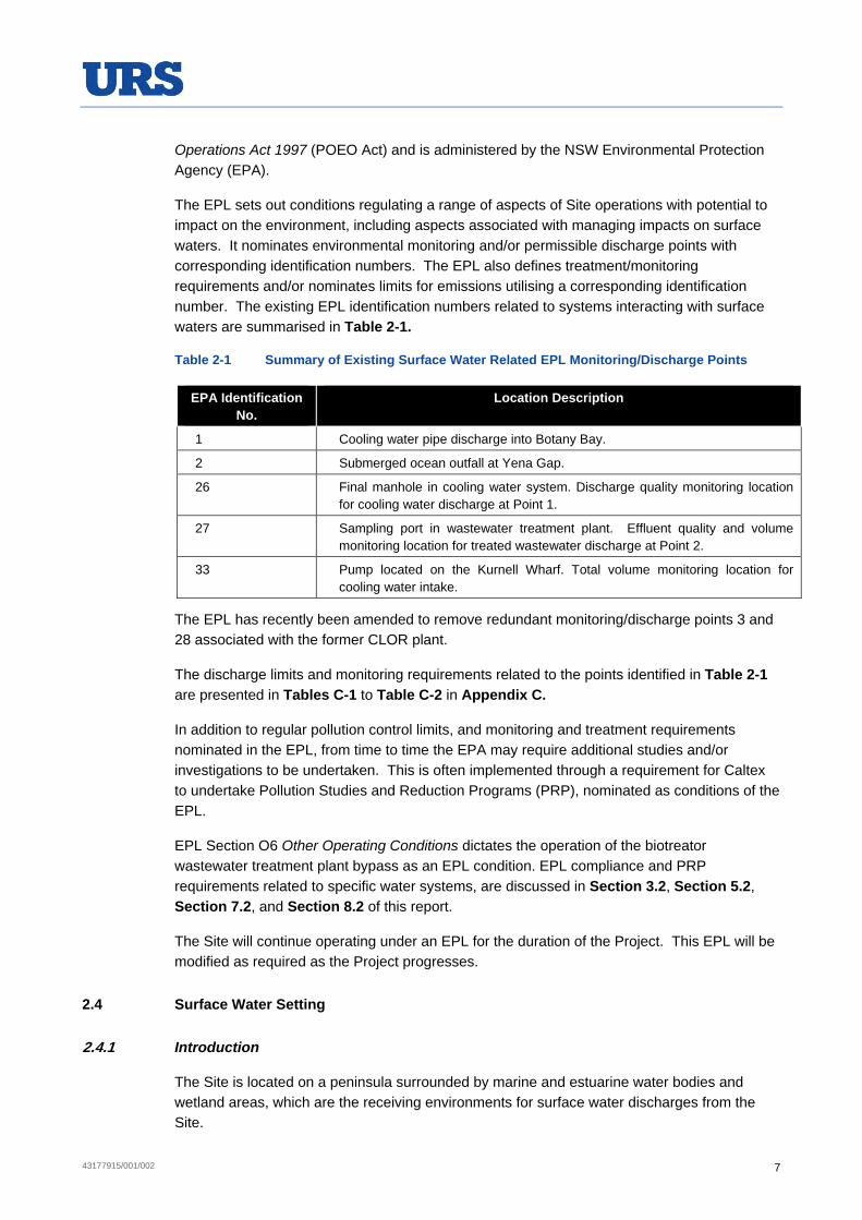
43177915/001/002 7
Operations Act 1997 (POEO Act) and is administered by the NSW Environmental Protection Agency (EPA).
The EPL sets out conditions regulating a range of aspects of Site operations with potential to impact on the environment, including aspects associated with managing impacts on surface waters. It nominates environmental monitoring and/or permissible discharge points with corresponding identification numbers. The EPL also defines treatment/monitoring requirements and/or nominates limits for emissions utilising a corresponding identification number. The existing EPL identification numbers related to systems interacting with surface waters are summarised in Table 2-1.
Table 2-1 Summary of Existing Surface Water Related EPL Monitoring/Discharge Points
EPA Identification No.
Location Description
1 Cooling water pipe discharge into Botany Bay.
2 Submerged ocean outfall at Yena Gap.
26 Final manhole in cooling water system. Discharge quality monitoring location for cooling water discharge at Point 1.
27 Sampling port in wastewater treatment plant. Effluent quality and volume monitoring location for treated wastewater discharge at Point 2.
33 Pump located on the Kurnell Wharf. Total volume monitoring location for cooling water intake.
The EPL has recently been amended to remove redundant monitoring/discharge points 3 and 28 associated with the former CLOR plant.
The discharge limits and monitoring requirements related to the points identified in Table 2-1 are presented in Tables C-1 to Table C-2 in Appendix C.
In addition to regular pollution control limits, and monitoring and treatment requirements nominated in the EPL, from time to time the EPA may require additional studies and/or investigations to be undertaken. This is often implemented through a requirement for Caltex to undertake Pollution Studies and Reduction Programs (PRP), nominated as conditions of the EPL.
EPL Section O6 Other Operating Conditions dictates the operation of the biotreator wastewater treatment plant bypass as an EPL condition. EPL compliance and PRP requirements related to specific water systems, are discussed in Section 3.2, Section 5.2, Section 7.2, and Section 8.2 of this report.
The Site will continue operating under an EPL for the duration of the Project. This EPL will be modified as required as the Project progresses.
2.4 Surface Water Setting
2.4.1 Introduction
The Site is located on a peninsula surrounded by marine and estuarine water bodies and wetland areas, which are the receiving environments for surface water discharges from the Site.

43177915/001/002 8
The main water bodies in proximity to the Site are:
Tasman Sea (‘the South Pacific Ocean’), located approximately 750 m due east of the Site, on the other side of the Kamay Botany Bay National Park;
Botany Bay, located about 500 m to the north of the main operational part of Site;
Quibray Bay, approximately 1 km to the west of the Site at its closest point. There is a mangrove wetland area between the Site and the Quibray Bay shoreline;
Weeney Bay, about 2.5 km due west of the Site on the other side of Quibray Bay; and
Marton Park Wetland on the northern Site boundary.
Quibray Bay and Weeney Bay are part of the Towra Point Aquatic Reserve and are connected to Towra Point Nature Reserve. Both these water bodies are connected to Botany Bay, which in turn is connected to the Tasman Sea and Pacific Ocean (refer to Figure A-2 of Appendix A).
2.4.2 Catchment
The Site is located within the Botany Bay catchment, which extends across an area of 1,165 km2. This catchment lies within the former Hawkesbury-Nepean Catchment Management Authority (HNCMA) area. Up until a few years ago, the catchment was within the Sydney Metropolitan Catchment Management Authority (SMCMA) area, before it was merged into the Hawkesbury-Nepean Catchment Management Authority. At the beginning of 2014, Catchment Management Authorities were abolished in NSW and the catchment is now part of the Greater Sydney Region of Local Land Service NSW.
The Botany Bay Catchment has four main sub-catchments, based on the major river systems and other areas that drain to it. These are the:
Georges River catchment;
Cooks River catchment;
Woronora catchment; and
Botany Bay (direct discharge) catchment.
The Site is located in the catchment area that drains directly to Botany Bay, as shown in Figure 2-1.

43177915/001/002 9
Figure 2-1 Botany Bay Sub-catchment Boundaries (SMCMA, 2011)
According to former Department of Sustainability, Environment, Water, Population and Communities (2010), Botany Bay and its catchment waterways are subject to ongoing threats arising from nutrient and sediment-laden run-off from various non-agricultural land uses. A substantial part of the catchment is highly developed with almost 40% of its area being used for urban, industrial or commercial purposes. Pollutants of concern include nitrogen, phosphorus and total suspended solids.
A number of studies have been commissioned through the Botany Bay Water Quality Improvement Program (which has been adopted as an ongoing program by Local Land Services NSW). This has included the Modelling the Catchments of Botany Bay Project conducted in October 2007 to simulate the generation of constituent pollutants under range of catchment land uses including rural lands, urban residential areas, and commercial, industrial and special use zones, e.g. airports, significant parklands and areas of native vegetation.

43177915/001/002 10
To facilitate the more detailed assessment of the modelling project, including the preparation of impact assessment modelling, the main catchments of Botany Bay have been further divided into sub-catchments, based on smaller drainage areas and drainage lines. These smaller sub-catchments have been defined, and named, in different ways within several references, e.g. in some references the Site is in the Mill Creek sub-catchment, which takes in all of the land adjoining southern Botany Bay, including the Kurnell Peninsula, while in others, there is a further catchment boundary through the spine of Towra Point Peninsula, with the eastern side referred to as Kurnell sub-catchment, shown in Figure 2-2.
The predicted pollutant load contributions from the Kurnell sub-catchment, as previously modelled by the SMCMA (2007), are presented in Table 2-2.
Table 2-2 Flow and Pollutant Load - Kurnell Sub-Catchment (SMCMA, 2007)
Parameter Load Concentration (mg/L)*
Total Catchment Flows (ML/yr) 6,300 N/A
Biological Oxygen Demand (BOD) (tonne/yr) 41 6.51
Faecal Coliforms (*10^9 counts/yr) 1,500 N/A
Total Organic Carbon (TOC) (tonne/yr) 66 10.48
Total Suspended Solid (TSS) (tonnes/yr) 300 47.62
Total Nitrogen (TN) (tonne/yr) 5.1 0.81
Total Phosphorous (TP) (tonne/yr) 0.58 0.09
*Calculated based on modelling results presented in the SMCMA report (2007)

43177915/001/002 11
Figure 2-2 Botany Bay Sub-Catchment (SMCMA, 2007)
2.4.3 Surface Waters and Environmental Values
The Site is close to a number of surface water features. These features support a range of environmental values and sensitivities including a number of areas of ecological value (refer to (Figure A-2). The surface water features close to the Site include:
Botany Bay;
Quibray Bay;
Towra Point Nature Reserve (including Ramsar wetland area);
Towra Point Aquatic Reserve;
SEPP 14 Wetlands;

43177915/001/002 12
SEPP 71 Coastal Protection Zone;
Marton Park Wetland (a Groundwater Dependent Ecosystem); and
Kamay Botany Bay National Park.
These areas and values are summarised in the following sections.
Botany Bay
Botany Bay is a shallow bay covering 4,600 hectares (ha) located approximately 10 km south of the Sydney CBD. It is used to access Sydney’s main commercial port (Port Botany). The Bay is designated a Special Port Area, and as such there are as number of controls regarding the management of the waters and waterside lands of the Bay (Sydney Ports, 2012). There are a number of competing economic, recreational and ecological interests related to the aquatic environment within the Bay, including aquatic ecosystems, primary industries such as aquaculture, recreation (e.g. fishing), aesthetic interests and cultural and spiritual values (SMCMA, 2007). As discussed in Section 2.4.2, Botany Bay and its catchment waterways are subject to ongoing environmental pressures.
Botany Bay contains areas of saltmarsh, seagrass and mangrove, particularly around the Towra Point Nature Reserve and the Towra Point Aquatic Reserve. It contains 40% of Sydney’s remaining mangrove communities and 60% of its remaining saltmarsh communities (DECCW & SMCMA, 2010). It is also host to many important bird species, including many listed in international migratory bird agreements, such as JAMBA, CAMBA, and ROKAMBA.
Quibray Bay
Quibray Bay is a small bay within Botany Bay that, in comparison to much of Botany Bay, has reasonable ecological condition. It lies within the Towra Point Aquatic Reserve. The bay contains significant seagrass, mangrove and saltmash habitat within its waters and around its shoreline (BBWQIP, 2011). The Towra Point Nature Reserve extends in a narrow fringe around Quibray Bay, encompassing a band of remnant saltmash. The northern side of the Bay is characterised by an extensive mangrove habitat area.
Towra Point Nature Reserve
Towra Point Nature Reserve, is a Ramsar Wetland and consists of 603.7 ha of wetlands that lie on the southern shores of Botany Bay, located approximately 16 km from the Sydney CBD (DECCW, 2010). The Reserve is bounded by the Kurnell Headland, Botany Bay, and Dolls Point. The most eastern extent of the Ramsar listed portion of the reserve is approximately 150 m west of the Site, on the western side of Captain Cook Drive (part of the Reserve fringes Quibray Bay, capturing remnant saltmash).
Stormwaters from part of the Site discharge into Quibray Bay (as discussed in Section 3), through drainage lines passing through the Towra Point Nature Reserve Ramsar site.
Towra Point Aquatic Reserve
Towra Point Aquatic Reserve surrounds Towra Point and covers an area of approximately 1,400 ha. The reserve is managed by the Fisheries Section of the NSW Department of

43177915/001/002 13
Primary Industries (DPI) and is divided into two zones. The aquatic wildlife refuge zone, in which some recreational fishing is permitted, extends around Towra Point Nature Reserve into Botany Bay. The “no-take” sanctuary zone is located within Quibray Bay and Weeney Bay (refer to Figure A-2). The reserve supports high levels of aquatic biodiversity, with more than 230 species of fish recorded within the reserve (NSW OEH National Parks and Wildlife Services (NPWS) 2012).
State Environmental Planning Policy 14 (SEPP14) - Coastal Wetlands
SEPP14 - Coastal Wetlands aims to protect and conserve coastal wetlands by ensuring that the coastal wetlands are preserved and protected in the environmental and economic interests of the state. SEPP 14 provides guidance for consent authorities, in terms of issues to consider when determining whether there is potential for a listed wetland to be affected by a Project. The provisions of this SEPP are not directly relevant to the demolition works or the Project, as no SEPP 14 designated wetlands are present within 5 km of the Site.
State Environmental Planning Policy (SEPP71) – Coastal Protection Zone
SEPP 71 - Coastal Protection aims to protect and manage the natural, cultural, recreational and economic attributes of the New South Wales coast through the preservation of a range of coastal values. The policy aims to:
guide development in the NSW coastal zone so that it is appropriate and suitably located;
ensure that there is a consistent and strategic approach to coastal planning and management; and
ensure there is a clear development assessment framework for the coastal zone.
The demolition works are outside the defined coastal zone for the Greater Metropolitan Region (Map 18).
Marton Park Wetland – Groundwater Dependant Ecosystem
Marton Park to the north of the Site comprises a wetland area and a small recreational park. The wetland is about 10 ha in size. Caltex owns approximately 3.4 ha of the wetland with the balance as public land. The Caltex owned wetland is a receiving environment for some Site stormwater runoff (refer to Section 3).
A review of the online GDE Atlas (funded by National Water Commission and hosted by the Bureau of Meteorology) identified that the wetland area is a vegetation related groundwater dependant ecosystem (GDE). The GDE Atlas noted that this freshwater wetland included fringing Threatened Species Conservation Act 1995 (TSC Act) listed Swamp Oak Sclerophyll Forest and Sydney Freshwater Wetlands (OEH 2013).
According to the Marton Park Wetland Management Plan (Molino Stewart Pty Ltd, 2009), the wetland is currently a freshwater wetland with limited tidal influence. The wetland plays an important role in the drainage of the surrounding area, including the eastern portion of Kurnell, part of the Site and the Kamay Botany Bay National Park. Much of the Site is bunded and surface runoff is treated onsite before discharging to Quibray Bay and Botany Bay, however, cleaner surface runoff from some non-industrial areas of the Site (e.g. the administration centre and some car parks) flows into this wetland, as well as stormwater from non-Refinery

43177915/001/002 14
areas via council drains. Marton Park Wetland is recharged by ground water seepage through the sandy bed during dry periods. Although not directly identified as a GDE within the Management Plan (Molino Stewart Pty Ltd, 2009), the interaction between the surface water and the ground water is acknowledged to be potentially high given the sandy nature of the soil.
Kamay Botany Bay National Park
Kamay Botany Bay National Park extends in an approximately 1 km band from north to south along the eastern coastline of Kurnell Peninsula, facing the Tasman Sea. The eastern boundary of the site forms part of the western boundary of the National Park. The National Park occupies an area of approximately 492 ha and supports a diversity of natural resources including threatened species and ecological communities and is recognised for its significant cultural heritage values (OEH, 2012a; NSW NPWS, 2002).
2.4.4 Environmental Water Quality Objectives
Introduction
The federal and all state and territory governments have adopted the National Water Quality Management Strategy for managing water quality, as set out in the Australian and New Zealand Environment Conservation Council (ANZECC) Australian and New Zealand Guidelines for Fresh and Marine Water Quality (2000) (‘the ANZECC Guidelines’).
The way in which these are applied in NSW is set out in Using the ANZECC Guidelines and Water Quality Objectives in NSW (Department of Environment and Conservation, 2006). The process involved establishing, in consultation with the community, the existing human uses and environmental values of a particular waterway, e.g. protection of aquatic ecosystems, primary contact recreation, irrigation water supply, etc. Water Quality Objectives, applicable to the agreed and endorsed (by the NSW State Government) environmental values, are then set, based on the ANZECC Guidelines. A protection level is applied based on the condition of the waterway e.g. high conservation value, highly disturbed ecosystem, etc., and specific waterway issues and risks are identified. Water quality indicators and trigger levels can then be established to allow the assessment and monitoring of the condition of the waterway.
Water quality objectives have been developed for all freshwaters and estuarine waters, and marine waters in NSW. Whilst water quality indicators and trigger values derived from the nominated objectives are not intended to be applied directly as regulatory criteria, limits or conditions, they are one factor to be considered by industry, the community, planning authorities or regulators when making decisions affecting the future of a surface water body to which they apply.
Water quality objectives are based on maintaining or improving the environment and the different uses of the waterway by the community. The guiding principles for responsible water quality management agencies, including Catchment Management Authorities, can be summarised as:
Where environmental values are being achieved in a waterway, these should be maintained; and
Where the environmental values are not being achieved the focus of activities should be towards achieving these values over time (SMCMA, 2007).

43177915/001/002 15
The EPL does not nominate stormwater discharge quality criteria. Therefore the potential impact of stormwater discharges on the water quality objectives of the relevant receiving waters has been considered within this assessment.
Botany Bay Catchment Water Quality Objectives
The water quality objectives for Botany Bay are broadly set out in the Marine Water Quality Objectives for NSW Ocean Waters: Sydney Metropolitan and Hawkesbury-Nepean (Department of Environment and Conservation NSW, 2005). The SMCMA was conducting the Botany Bay Water Quality Improvement Program through which it ultimately developed and published the Botany Bay & Catchment Water Quality Improvement Plan (SMCMA 2011). Through this process, specific Botany Bay water quality objectives were developed and published in the: Botany Bay Coastal Catchments Initiative Environmental Values – Background Paper (SMCMA, June 2007). The Botany Bay Water Quality Improvement Program has been adopted by Local Land Office NSW and will continue.
The water quality values defined for the Georges River Catchment, including the southern parts of Botany Bay (including receiving environments relevant to the SIte) are the protection of:
aquatic ecosystems – to maintain or improve the ecological condition of waters;
primary contact recreation – to maintain or improve water quality so that it is suitable for activities such as swimming and other direct water contact sports;
secondary contact recreation– to maintain or improve water quality so it is suitable for activities such as boating and fishing where there is less bodily contact with the waters;
visual amenity – to maintain or improve water quality so that it looks clean and is free of surface films and debris; and
aquatic foods (cooked) – to maintain or improve water quality for the production of aquatic foods for human consumption (whether derived from aquaculture or recreational, commercial or indigenous fishing).
Specific catchments within the Georges River catchment, including part of Botany Bay that are potentially applicable to the Site, their current environmental conditions, the desired outcomes and goals for those areas, as well as the ANZECC levels of protection afforded to them are summarised in Table 2-3.
Table 2-3 Management Goals and ANZECC Protections Levels – Botany Bay (Healthy Rivers Commission of New South Wales, 2007)
Catchments Environment condition Desired outcomes Management
goal
ANZECC Levels of
Protection
Upper Georges River, Towra wetlands & Woolooware Bay
Slightly modified
Restore natural processes and biodiversity as much as practicable.
Restore natural condition
Slightly to moderately disturbed
Georges River estuary and southern Botany Bay.
Moderately modified
Retain or restore important natural processes/ biodiversity and protect desired public uses.
Maintain or restore healthy modified conditions
Slightly to moderately disturbed

43177915/001/002 16
Marine Water Quality Objectives
Treated wastewater from the WWTP is discharged into the Tasman Sea via the Yena Gap outfall. The Tasman Sea is classified as a marine water environment. The marine water quality objectives are set out in the Marine Water Quality Objectives for NSW Ocean Waters:
Sydney Metropolitan and Hawkesbury-Nepean (Department of Environment and Conservation NSW, 2005). The Marine Water Quality Water Objectives/Environmental Values set out for marine waters in the vicinity of the Site are:
aquatic ecosystem health – to maintain or improve the ecological condition of oceans waters;
primary contact recreational – to maintain or improve ocean water quality so that it is suitable for activities such as swimming and other direct water contact sports;
secondary contact recreation – to maintain or improve ocean water quality so it is suitable activities such as boating and fishing where there is less bodily contact with the waters;
visual amenity – to maintain or improve water quality so that it looks clean and is free of surface films and debris; and
aquatic foods – to maintain or improve ocean water quality for the production of aquatic foods for human consumption (whether derived from aquaculture or recreational, commercial or indigenous fishing).
The potential impact of the proposed works on Marine Ecology is specifically addressed in Appendix G2 Marine Ecology Impact Assessment.

43177915/001/002 17
3 STORMWATER
3.1 Introduction
This section provides an assessment of the potential stormwater impacts of the proposed demolition works, providing:
descriptions of the existing catchments present across the Site;
a description of the existing stormwater collection and treatment infrastructure;
a description of the stormwater discharge points from the Site; and
an assessment of the water quantity and quality impacts of stormwater, with reference to the proposed demolition activities.
3.2 Existing Environment
3.2.1 Overview
Stormwater generated on the Site is collected in the Site’s stormwater system. All of the stormwater that could potentially come from process areas is treated, and is discharged offsite into three receiving water bodies, Quibray Bay and Botany Bay, or Marton Park Wetland. The stormwater system only collects runoff from areas of the Site that have been designated low risk with respect to interaction with petroleum products, including primarily the ‘non-process’ areas of the Site, such as roadways and building roofs.
The Site has a separate oily water system to handle water that is or may be impacted by petroleum products, including a proportion of stormwater runoff collected from areas where there is or may be interaction with petroleum products such as tanks, bunds and refinery process areas. The oily water system is addressed briefly in Section 3.2.3 and in detail in Section 5 of this report.
Topography within the Site is generally flat, although steeper areas exist toward the eastern Site boundary. Soils within the Site are sandy with sandstone bedrock.
The Site has seven main stormwater catchment areas, which eventually discharge to Quibray Bay, Botany Bay, or to land in Marton Park Wetland. Stormwater runoff generally flows from the eastern boundary through pipes and open channels towards the northwest into the Quibray Bay, Botany Bay, and Marton Park Wetland. Some stormwater flows onto the Site across the eastern Site boundary from the Kamay Botany Bay National Park.
Caltex prepared a Stormwater Management Plan (dated 5/10/11) in response to a Pollution Reduction Program formerly included within EPL No 837. This requirement was imposed by EPA in response to several incidents in 2010/11 arising from flooding on the Site. The Stormwater Management Plan was based on a comprehensive review of the stormwater system, including hydraulic modelling, conducted in 1992 (CRL/ALOR Stormwater
Management Study (GHD, 1992)). This was a major update of an assessment undertaken in 1981 entitled: Stormwater Drainage Investigation (Davy McKee, 1991).
Since the preparation of the EIS for the Kurnell Refinery Conversion Project, (URS, 2013) Caltex has progressed a number of improvement actions as part of the Stormwater Management Strategy. This strategy is described in Section 3.2.6.
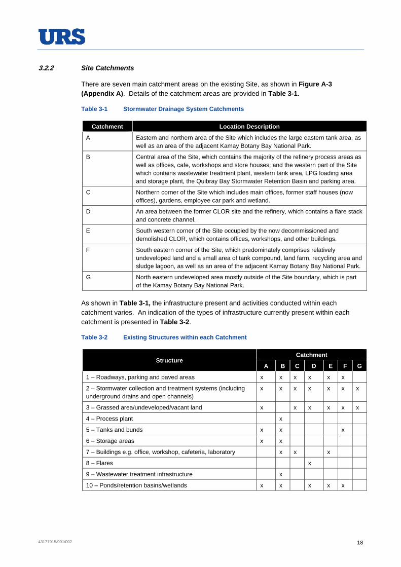
43177915/001/002 18
3.2.2 Site Catchments
There are seven main catchment areas on the existing Site, as shown in Figure A-3 (Appendix A). Details of the catchment areas are provided in Table 3-1.
Table 3-1 Stormwater Drainage System Catchments
Catchment Location Description
A Eastern and northern area of the Site which includes the large eastern tank area, as well as an area of the adjacent Kamay Botany Bay National Park.
B Central area of the Site, which contains the majority of the refinery process areas as well as offices, cafe, workshops and store houses; and the western part of the Site which contains wastewater treatment plant, western tank area, LPG loading area and storage plant, the Quibray Bay Stormwater Retention Basin and parking area.
C Northern corner of the Site which includes main offices, former staff houses (now offices), gardens, employee car park and wetland.
D An area between the former CLOR site and the refinery, which contains a flare stack and concrete channel.
E South western corner of the Site occupied by the now decommissioned and demolished CLOR, which contains offices, workshops, and other buildings.
F South eastern corner of the Site, which predominately comprises relatively undeveloped land and a small area of tank compound, land farm, recycling area and sludge lagoon, as well as an area of the adjacent Kamay Botany Bay National Park.
G North eastern undeveloped area mostly outside of the Site boundary, which is part of the Kamay Botany Bay National Park.
As shown in Table 3-1, the infrastructure present and activities conducted within each catchment varies. An indication of the types of infrastructure currently present within each catchment is presented in Table 3-2.
Table 3-2 Existing Structures within each Catchment
Structure Catchment
A B C D E F G
1 – Roadways, parking and paved areas x x x x x x
2 – Stormwater collection and treatment systems (including underground drains and open channels)
x x x x x x x
3 – Grassed area/undeveloped/vacant land x x x x x x
4 – Process plant x
5 – Tanks and bunds x x x
6 – Storage areas x x
7 – Buildings e.g. office, workshop, cafeteria, laboratory x x x
8 – Flares x
9 – Wastewater treatment infrastructure x
10 – Ponds/retention basins/wetlands x x x x x

43177915/001/002 19
3.2.3 Stormwater System Description
The Site has a stormwater management system that separates stormwater from potentially impacted water, including some impacted stormwater (for management via the oily water sewer system).
Rainwater that falls within tank bund areas or within the refinery process area (including the former CLOR oily water sewer system), and which could potentially be impacted, is currently directed to the Site oily water sewer system, for treatment in the wastewater treatment plant (WWTP). The treated wastewater from the WWTP is then discharged via an outfall to the ocean in accordance with the Site’s EPL. This is discussed further in Section 5.
There has also been an intermediate sewer system (part of the cooling water system) to which potentially impacted stormwater from the stormwater system can be manually directed for treatment by oil/water separators prior to discharge via the Botany Bay cooling water outfall. As part of the conversion works, the cooling water system is being decommissioned and will therefore no longer be available. This process will occur in the second half of 2014. The intermediate sewer system oil water separators will be directed to the Site oily water sewer system instead.
The stormwater system collects runoff predominately from roadways and hardstand areas, roof runoff, and pipeways, as well as undeveloped areas of the Site. Some runoff from offsite is also intercepted by the Site’s stormwater system, e.g. Catchment G includes part of the Kamay Botany Bay National Park.
The stormwater collection system comprises a system of underground reticulation and open channels. There are various retention, retarding and treatment systems incorporated into the Site’s stormwater system.
The specific stormwater retention, treatment and disposal systems in each catchment are discussed further in Appendix C and summarised in Table 3-3. This table also identifies where offsite inflow into the Site catchments is occurring (also shown on Figure A-3).
Table 3-3 Stormwater Storage, Treatment and Disposal within each Catchment
Catchment Offsite Inflow Retention Treatment/Control Discharge Point(s)
A Inflow from the Kamay Botany Bay National Park at five (5) points along the eastern boundary
There is a natural retention area present, receiving inflow from the National Park and surrounding area.
Skimmer and siphon system, followed by API oil/water separator. Provision for pipeway isolation and use of skimmer pump to the oily water sewer system. Retention in the south east part of the catchment.
Botany Bay offshore from Silver Beach

43177915/001/002 20
Catchment Offsite Inflow Retention Treatment/Control Discharge Point(s)
B No direct inflow. Can receive overflow from Catchment A during major storm events contributed to by National Park inflows entering that catchment
Quibray Bay Stormwater Retention Basin. Basin overflow
API separator. Retention basin. Siphon system. Final discharge pit. Provision for isolation, skimming and diversion of Pipeway A & B drainage to intermediate sewer and use of skimmer pump to the oily water sewer system.
Quibray Bay via Captain Cook Drive roadway drains discharging into drainage lines that pass through the mangrove wetland.
C None identified Possibly some in onsite wetland area.
None identified, though some treatment would be provided in the onsite wetland area.
Marton Park Wetland
D None None Transferred to Catchment B, Treatment as indicated for that catchment.
Transferred to Catchment B. Discharge as indicated for that catchment.
E None Some onsite infiltration occurs in the former process area.
Stormwater collected in the former CLOR oily water sewer system is pumped to the refinery oily water sewer system.
Quibray Bay via Sir Joseph Banks Drive and Captain Cook Drive roadway drains discharging into drainage lines that pass through the mangrove wetland. Onsite infiltration.
F Inflow from the Kamay Botany Bay National Park via two (2) main drainage lines along the eastern Boundary
Natural retention basin
Retention Quibray Bay via Sir Joseph Banks Drive and Captain Cook Drive roadway drains discharging through the mangrove wetland.
G Inflow from the Kamay Botany Bay National Park in the north west corner of the Site.
None None Sutherland Shire drains, which discharges to Marton Park Wetlands
43177915/001/002 21
With reference to Table 3-1, Table 3-2 and Table 3-3 above, Catchment D is no longer a separate catchment, and is now part of Catchment B. It was originally a separate catchment that drained to an infiltration area in the west of the Site. This area is now occupied by a tank and the drainage was modified to accommodate the construction of it. It has been maintained as a separate catchment within this report for consistency with the Stormwater Management Plan for the Site and the preceding stormwater catchment definitions.
The main Site catchments with the potential for interaction between petroleum products and stormwater are Catchments A and B (including Catchment D), primarily along the pipeways. These are also the catchments in which the majority of the demolition works would occur.
The systems incorporated into the stormwater system to regulate flow and discharge rates and prevent discharge of impacted stormwater from the Site are summarised as follows:
provision for isolation of drainage in pipeways;
installation of manually operated skimmer pumps at pump transfer points (pumping to the oily water sewer system);
ability to redirect stormwater to the intermediate sewer (Catchment B [including Catchment D] only);
retention in an onsite retention basin (Catchment B [including Catchment D] only);
discharge via siphon systems; and
treatment in API oil/water/solids separators.
As the CLOR has ceased operation and has been demolished, runoff from this area is no longer treated prior to offsite discharge. The only exception is water that collects in the former CLOR oily water sewer system, which is now pumped to the Refinery oily water sewer system.
Activities and infrastructure in Catchment C and part of Catchment F are not dissimilar to those generally in commercial urban areas. Catchment G and much of Catchment F is undeveloped land. Runoff from these areas is, consequently, similar to urban or undeveloped land runoff and is discharged offsite without onsite treatment.
An analysis of the stormwater system’s operational hydraulics was conducted in 1992 using the ILSAX computer modelling program. The model was run for each of the catchments, for a range of storm durations. The modelling assessed and identified hydraulic and treatment capacity constraints within the Site’s stormwater system. A range of consequential modifications and improvements were made to the system over a period of time. Also, modifications to the Site catchment and stormwater system have occurred in the intervening period due to operational and infrastructure changes on the Site, e.g. diversion of Catchment D to Catchment B due to the construction of a new tank.
Some capacity constraints were identified in Catchment B in the early 2000s prompting the EPA to require an assessment and improvements under a Pollution Study and Reduction Program (PRP) for stormwater water quality (PRP U5). This plan was submitted on 5th October 2005 and has subsequently been implemented.
The response of the system to some high rainfall events in 2010/11 indicated that some capacity constraints remained within Catchment B related in part to inflow from the adjoining National Park. As such, the EPA required that Caltex prepare a new Stormwater Management

43177915/001/002 22
Plan, which is continuing to be implemented (discussed further in Section 3.2.6). Commitments made include an update of the stormwater hydraulic model to identify and optimise the system capacity..
Broadly, Caltex aims to minimise the interaction between stormwater and hydrocarbons and other contaminant sources. The conversion works will ultimately result in an increase in clean catchment areas on the Site. Caltex will continue to assess and implement improvement measures to achieve a more efficient distribution of stormwater through the existing infrastructure and to reduce localised flooding.
3.2.4 Stormwater Quality
The current stormwater treatment systems described in Section 3.2.3 are designed to address the following types of contaminants:
suspended solids (settleable); and
phase separated petroleum hydrocarbons.
The key water quality management strategy adopted by the Site has been to prevent, to the extent practicable, interaction between petroleum hydrocarbons and stormwater.
As discussed in Section 3.2.3 the main stormwater quality threats arise from Catchments A and B. The remaining catchment areas have a lower risk of impacting significantly on stormwater quality.
It is expected that when stormwater flows are within the hydraulic and treatment capacity of the Site’s systems, the stormwater quality would exhibit similar characteristics to stormwater runoff from urban areas. This assessment is based on:
the nature of the existing infrastructure, products, and activities (refer to Table 3-2 and Table 3-3) within the stormwater system catchments;
the fact that the Site’s stormwater management system separates stormwater and oily water; and
the reduced risk of discharging impacted stormwater as a result of retention treatment of stormwater for the removal of oil and sediment.
As discussed in Section 3.2.3, a Pollution Study and Reduction Program (PRP) for stormwater water quality (PRP U5) was completed in March 2005. This PRP sought to improve the quality of stormwater treatment so as to ensure that no visible oil and grease would be released within the waters discharged adjacent to Gate 5 to Quibray Bay (EPAa 2012). Under PRP U5, the Quibray Bay Stormwater Retention Basin (formerly known as Basin B1) was upgraded to allow stormwater from Pipeways A and B to be directed to the basin before discharging offsite.
On three separate occasions in June 2010, March 2011 and April 2011, during periods of very high rainfall, oily water has been discharged from the Site. This occurred due to flooding in Catchment B. The discharge occurred through the cooling water outfall into Botany Bay. Therefore, the ability of the Site’s stormwater systems to mitigate and manage offsite impacts during flood events has required further assessment. In relation to these specific incidents in 2010 and 2011, it was identified that the incidences were due to heavy rainfall that resulted in

43177915/001/002 23
localised flooding at the WWTP and adjacent properties, which resulted in oily water being discharged offsite. The assessment found that during heavy rainfall, due to the slow release rate of stormwater from the Main Pipeway skimmer and syphon system, stormwater may back up and form pools upstream of the syphon, and if the stormwater backs up as far as the Oil Movement Centre (OMC), it could enter the oily water sewer. This would put pressure on the capacity of the WWTP, potentially causing flooding at the Oily Water Separators. This would discharge to stormwater, which is what occurred. In addition, the assessment found that if the stormwater backs up all the way to where Pipeways A and B intersect the Main Pipeway, the stormwater in the Main Pipeway can enter Pipeway A and B, thus overloading Catchment B drainage system, which may also cause flooding further down the system.
In response to these additional stormwater quality impact issues within the Catchment B stormwater system, the EPA imposed a requirement for additional stormwater improvement investigations within U10 PRP U24: Stormwater Catchment and Management Program. Caltex was required to prepare a Stormwater Management Plan to prevent the discharge of contaminated waters from the Site at all times. This plan was prepared and submitted as required on 5 October 2012. Its’ findings were considered as part of this assessment. Details of the Stormwater Management Plan strategies and recent improvements are discussed further in Section 3.2.6.
A further similar incident to those which occurred in 2010/11 was alleged after a very high rainfall event in March 2014. The EPA alleged that a small amount of oily residue detected along the shoreline between Yarra Bay and Congwong Bay in Botany Bay derived from localised flooding of Catchment B at the Site. Caltex completed an ecological assessment of the impact area which concluded that there were no discernible impacts on local biota. Caltex continues to work with the EPA to implement the ongoing stormwater improvement strategy to prevent localised flooding.
3.2.5 Stormwater Discharge
Stormwater from the Site is discharged, ultimately, to three receiving environments, namely:
discharge by open drainage lines to Quibray Bay through a narrow strip of the Towra Point Nature Reserve and the mangrove wetland;
discharge into Botany Bay (offshore from Silver Beach near Kurnell Wharf); and
discharge to Marton Park Wetland – loss primarily by infiltration.
A description of the discharge arrangements from each catchment is provided in Appendix C, and summarised in Table 3-3.
Catchments B, D, E & F, comprise approximately 70% of the total Site catchment area. These catchments all discharge ultimately to Quibray Bay via aboveground drainage lines passing through a narrow strip of the Towra Point Nature Reserve (of remnant saltmarsh) and the mangrove wetland on the northern side of Quibray Bay.
Quibray Bay (and surrounds) is therefore the main receiving environment and is also the most environmentally sensitive of the current stormwater receiving environments.

43177915/001/002 24
3.2.6 Further Stormwater System Assessment and Improvement
The Stormwater Management Plan (SMP) prepared for the Site under a previous EPL PRP condition (PRP U24.1), committed Caltex to implementing a stormwater management strategy and to completing a number of stormwater management measures in a staged manner. The various elements of the strategy are as follows:
1 Ongoing maintenance of the existing stormwater system (ongoing). 2 Implement a number of projects to improve the infrastructure, reduce the potential for the
Site to flood, and prevent contaminated stormwater leaving the Site (commenced in 2012). 3 Work with the NSW Office of Environment and Heritage, NSW EPA and Sutherland Shire
Council to divert to flow of stormwater from the National Park away from the Site’s stormwater system to the Sutherland Shire Council’s stormwater infrastructure (commenced in 2012).
4 stormwater flow monitoring to improve understanding of current site stormwater flows (ongoing).
5 Update the Site’s stormwater system performance model to account for the changes to the stormwater system infrastructure that can then be used as a tool to assess future modifications, as necessary (will commence once Strategy Item 2 has been finished).
6 Carry out further stormwater system hydraulic performance monitoring and review the model, as necessary, following the implementation of the proposed projects to reassess the adequacy of the stormwater system for meeting the objective to “prevent the discharge
of contaminated waters from the premises at all times”. Depending on the outcome of the review, further projects may be developed to improve the stormwater system.
The SMP has now been partly implemented by Caltex and implementation is ongoing. The key actions that have been taken to date include:
Element 1: All major stormwater infrastructure on the Site was inspected by CCTV and cleaned in 2013.
Element 2: A number of specific stormwater system improvement projects have been implemented, including:
– Modification Main Pipeway siphon system and installation of a new oil skimmer to improve performance of these systems.
– Construction of retention walls to prevent stormwater from the Main Pipeway in Catchment A from entering Pipeway A & B in Catchment B.
– Increase in the bund height of some Oily Water System infrastructure to reduce the potential for interaction between this system and stormwater.
– Diversion of runoff from a contractors carpark in Catchment B to Catchment C to reduce load on Catchment B systems; and
– Hydraulic improvement to stormwater retention and treatment systems in Catchment B to reduce the potential for flooding in this area.
Element 3: Design of a National Park Stormwater Diversion system has been completed. This involves intercepting some of the Kamay Botany Bay National Park stormwater inflows in Catchment A at the eastern Site boundary and diverting these via a relined pipeline inside the refinery’s northern and western perimeter directly to the lower part of

43177915/001/002 25
the catchment where the stormwater flows into the main pipeway. This project is currently being implemented and is planned to be completed in the first quarter of 2015.
Element 4: Stormwater flow monitoring to improve understanding of Site stormwater flows has commenced to the extent required to support the modelling work.
Catchments A and B, the main Site catchments in which the review and improvement measures are focussed, are the main areas where the demolition works would take place.
The remaining SMP actions include:
the preparation of an updated hydraulic and site stormwater model to be utilised as a tool to assess the impact of proposed stormwater system modifications associated with the conversion works; and
the identification of further system improvements (Elements 5 & 6).
The preliminary part of the modelling work has commenced and is likely to be completed prior to the commencement of major demolition activities.
3.2.7 Offsite Stormwater Interceptions and Groundwater Interaction
Offsite Stormwater Interception
As noted in Table 3-1 and Table 3-3, the Site intercepts stormwater that enters into Catchments A, F and G from the Kamay Botany Bay National Park. The offsite catchment areas and points at which this stormwater enters the Site are shown in Figure A-3 of Appendix A.
The offsite catchments were clearly defined, and some inflow modelling was conducted in the 1992 stormwater study (GHD 1992). This report considered the potential diversion of stormwater from the National Park and informed the recent diversion works for Catchment A (as described under Element 3 in Section 3.2.6 above). The ultimate discharge point of this stormwater is to Botany Bay. In effect, the water still discharges to the same receiving waters as before, however the hydraulic load on parts of catchment A and B drainage network is reduced. Stormwater runoff from Catchment G is channelled in both council and on-site drains and discharges into Marton Park.
Inflows into Catchment F, whilst significant, do not interact with the stormwater system in the operational areas of the Site and so are effectively diverted around the southern Site boundary (ultimately discharging to Quibray Bay). There is very limited proposed demolition activity in this catchment.
Groundwater Interactions
There is the potential for interaction between stormwater and groundwater at the Site. Groundwater is addressed separately in Chapter 9 Soil, Groundwater and Contamination of the SEE.
There may be groundwater intercepted in excavations during the demolition works. This is discussed in Section 6.2.1.

43177915/001/002 26
Infiltration of stormwater to soil, and potentially, to the underlying groundwater occurs in parts of the Site that are unpaved and pervious. Where there are permanent or temporary water bodies, such as ponds, natural retention basins or wetlands, the interaction may be more direct. These areas on Site are shown on Figure A-3 and include:
natural retention area in Catchment A;
Quibray Bay stormwater retention basin overflow retention areas (Catchment B);
an onsite wetland area (adjacent to Marton Park Wetland), north of the contractors carpark (Catchment C);
a natural retention basin near the southern site boundary (Catchment F); and
parts of the former CLOR process area (Catchment E).
Marton Park Wetland is one of the identified destinations for Site stormwater (Catchments C and G) and is also a designated GDE, as discussed in Section 2.4.3, in Chapter 9 Soil, Groundwater and Contamination, and in Chapter 17 Ecology of the SEE. Groundwater interaction and infiltration could also be expected within the Quibray Bay wetland area, which is the destination for stormwater from Catchments B, D, E and F.
The Kamay Botany Bay National Park, located along the eastern Site boundary, is generally elevated above the level of the Site. It consists of sandy soils, and so relatively high stormwater infiltration rates would be expected in this area. It is conceivable, though not confirmed, that groundwater may be contributing to intercepted stormwater flows on the Site (i.e. from spring contributions), particularly following high rainfall events.
The stormwater/groundwater interactions at the Site have not previously been quantified. Further such interactions may be identified as a result of preparing the Site stormwater model at the completion of the conversion works, under the Stormwater Management Plan (refer to Section 3.2.6).
3.3 Impact Assessment
3.3.1 Demolition Works
Overview
The demolition works would be largely completed within Catchments A and B, but as can be seen in Figure A-1, with reference to Figure A-3, demolition works would occur in all catchments except G.
The demolition works would commence in 2015 and would consist of:
Demolition of the refinery process units and associated pipelines;
Removal of the foundations for the process units and redundant slabs;
Removal of redundant cabling and underground services including the Oily Water Sewer from the area beneath the refinery process units;
Demolition of numerous tanks and storage vessels within the Eastern and Western Tank Areas;

43177915/001/002 27
Removal of seven underground pipelines including:
– the cooling water outlet line from the western right of way;
– two cooling water intake lines from the eastern right of way;
– three redundant product lines running through the eastern right of way; and
– the Continental Carbon pipeline running south from the refinery process units to the edge of Caltex’s land ownership.
– The removal of redundant pipelines from the two Rights of Way (ROW) (eastern and western) would require excavating sections of Captain Cook Drive, Torres Street, Cook Street and Prince Charles Parade where the pipelines intersect these roads. The redundant pipelines would be excavated, pipelines removed and the surface returned to grade including in-kind road repairs for disturbed sections of roadway.
– North of the Western ROW and Prince Charles Parade, the cooling water outlet pipe would be excavated and removed from beneath the dune, beach, intertidal area, and for up to 20 m seaward from the low tide mark into Botany Bay. The remaining section of the pipe would be left in situ in Botany Bay.
– North of the Eastern ROW and Prince Charles Parade, the two cooling water inlet pipelines move from underground to aboveground and are mounted on Kurnell Wharf. These pipelines would be removed and craned onto a truck on the wharf by a barge crane. Some pump infrastructure from the wharf pumphouse would also be removed.
Demolition and removal of a number of buildings on Site relating to the refinery operation as well as excavation of connecting services and foundations
Potential impacts related to stormwater associated with the demolition works include those arising from demolition and ground disturbance works (i.e. impacts to storm water run-off quality), as well as potential changes to the operation and functioning of stormwater catchments in the short and longer term (i.e. catchment hydraulics).
Construction/Demolition Impacts
During construction/demolition works, stormwater quality impacts could arise from a range of factors, including:
erosion and entrainment of dust, soil and other material in stormwater from areas where ground disturbance works and excavation are required;
leaks of fuel and hydraulic fluid from various plant items required for the demolition works potentially impacting on stormwater quality;
leaks of residual matter from within redundant plant and equipment prior to removal, which could impact rainwater runoff quality; and
impact on stormwater quality arising from interaction with contaminated soils potentially exposed by demolition and/or excavation works.
The management of potential impacts on stormwater runoff quality during the demolition works would be detailed within a Demolition Environmental Management Plan (DEMP) for these works. The DEMP would include aspect specific management plans including a

43177915/001/002 28
Contamination Management Plan and a Water Management Plan for the demolition works, consistent with its approach for the conversion works.
Although the total area affected by ground disturbance work, including excavation of footings, is significant, the works would be staged, effectively minimising the area of ground disturbing activities at any one time. All work would be undertaken in a manner to minimise the potential for soil erosion and sedimentation and in accordance with the measures outlined in the Managing Urban Stormwater – Soils and Construction (NSW Department of Housing, 2004) (commonly referred to as the Blue Book guidelines).
Areas that would be disturbed would be managed through the installation and maintenance of appropriate erosion and sedimentation control devices. This may include the installation of sediment filters across drains and along roads where pipelines to be removed. Sediment control devices would remain in place until the road sections are repaired or surface is restored to capture gross pollutants. Temporary containment bunds would be constructed to collect spilt demolition material. Waste collection areas would be designated. Bunding would be installed and containers would be provided for liquids. Waste collection and disposal would be undertaken by licensed contractors where necessary (refer to Chapter 11 Waste Management of the SEE).
Catchments A and B, where most of the demolition works would occur, both have controls in-place that remove suspended solids from stormwater by sedimentation and oil by gravity separation which would remain in place throughout the duration of the demolition works (refer to Section 3.2).
Given that the demolition works are planned to proceed following the deinventory, depressurisation and cleaning of redundant plant, it is expected that only minor amounts of hydrocarbon residues would potentially be present prior to the demolition works occurring. The removal of redundant pipelines and demolition of tanks and process unit areas to grade however has the potential to unearth contaminated soils, which if exposed, could impact stormwater runoff quality. The assessment of impacts arising from contaminated soils and the management of those is provided in Chapter 9 Soils, Groundwater and Contamination of the SEE.
Measures to be implemented during the demolition works to protect stormwater quality include:
Stormwater or intercepted groundwater ponded in excavations is to be tested prior to direction to stormwater (if suitable quality) or the oily water sewer system;
Removal of surface soils impacted with hydrocarbons and/or asbestos to prevent stormwater quality impacts;
Installation and maintenance of silt fencing and/or alternate sediment control measures around soil stockpiles and disturbed areas or areas where dust suppression is being undertaken as required and appropriate;
Regular inspection of soil stockpiles/excavation areas, including following rainfall events; and
Regular inspections of stormwater drains down hydraulic gradient of disturbed areas.
These measures would be relevant to the demolition works, notably in the refinery process area.

43177915/001/002 29
Some oily water sewer infrastructure connecting process units and from beneath the refinery process areas is to be removed as part of the demolition works. Stormwater previously directed to the oily water sewer would then be directed to the stormwater system, infiltrate into the ground or evaporate. If during the demolition works, stormwater quality is impacted through the disturbance of contaminated soils or sediment, the potential for use of sucker trucks or diversion of stormwater to the intermediate sewer system exists and would be used as required.
3.3.2 Post Demolition Phase
The existing Site stormwater system with its stormwater retention and treatment systems, would remain intact once all of the demolition works are complete. The Site stormwater receiving environments would also not change.
The main ongoing potential impact on catchment yields following the demolition works are on Catchment B, where the refinery process units are located, as shown in Figure A-1 in Appendix A. These areas would be disconnected from the oily water sewer system and some bunding and oily water sewer system connection infrastructure would be removed. Infrastructure above grade, and some foundations and concrete slabs would also be removed.
The removal of this infrastructure in the refinery process area would increase the effective area of Catchment B, and hence stormwater yield. However, the increase in yield would not be expected to be proportional to the increase in area. This is because the removal of the hard surface areas within the refinery process area would decrease the amount of runoff generated compared to when the area previously discharged to the oily water sewer system. Overall, the impact on the system hydraulics is not expected to be significant but this would be confirmed by the modelling to be conducted for the SMP.
Following the demolition phase, bunded tank farm areas would remain connected to the oily water management system (OWMS), regardless of whether they contain tanks. Bunds would be drained by manual drain valve operation.
The quality of stormwater arising from the Site during and following the demolition works would be of a similar character as is currently the case. Impacted water would be directed to the OWMS and managed in accordance with the EPL. Stormwater would be managed with existing systems and during demolition, by implementing the additional measures specified in the DEMP. Ultimately, the shutdown and decommissioning of the refinery process units would reduce the potential for impact on stormwater quality by petroleum products in both Catchment A and B stormwater due to the significant reduction in associated product transfers.
Overall, the change in volume and quality of stormwater discharged from the Site, arising from the demolition works is not expected to be significant.
The Site stormwater system would continue to be reviewed and improved in line with the requirements of the Stormwater Management Plan, as indicated in Section 3.2.6.

43177915/001/002 30
3.3.3 Offsite Stormwater Interceptions and Groundwater Interaction
Offsite Stormwater Interception
The demolition works are likely to have no significant influence on the interception of offsite stormwater flows within the Site.
The implementation of the Contractors’ Carpark Diversion sub-project as part of the wider Stormwater Management Plan increases the discharge of stormwater to Marton Park. Caltex has developed and implemented a flora and fauna monitoring program for the Caltex owned part of Marton Park Wetland, consistent with the Council approval obtained for this sub-project (shown on Figure A-3 of Appendix A).
The Kamay Botany Bay National Park Diversion Project will have the effect of reducing the hydraulic load on some of the Site stormwater systems however does not impact on the destination of this stormwater to Botany Bay via the main pipeway.
Groundwater Interaction
The interaction between surface water and groundwater at the Site may increase as a consequence of the demolition works through the removal of hardstand/foundation areas, primarily in the in refinery process area (Catchment B). The removal of hard surfaces would result in an overall increase in surface water infiltration at the Site. During demolition works, there is also potential for some interception of groundwater in excavations below about 1 mbgl. Potential impacts arising from this will be assessed in Chapter 9 Soils, Groundwater and Contamination of the SEE.

43177915/001/002 31
4 FLOOD RISK
4.1 Introduction
This section presents an assessment of the flood risk at the Site. The assessment provides:
descriptions of the existing flood risk including tsunami and surface water/flash flooding; and
an assessment of the flood risk, with reference to modifications as a result of the demolition works.
4.2 Existing Environment
4.2.1 Introduction
The Site lies at south eastern portion of the Kurnell township catchment. According to the Kurnell Township Flood Study Final Report (WMAwater, 2009), prepared on behalf of Sutherland Shire Council, Kurnell is susceptible to flooding from both rainfall and tidal inundation. Its localised depression and low lying topography can make it vulnerable to extensive flooding (WMAwater, 2009).
Flooding within the Kurnell Catchment may occur as a result of the following factors, which may occur in combination or in isolation:
high tide or storm surge which causes water levels to elevate in Botany Bay and Quibray Bay;
intense rainfall which causes water levels to elevate within the open channel that runs beside Captain Cook Drive and along roads and through private property. The rise in water level may also be affected by constrictions, e.g. culverts, blockages, fences and buildings;
local runoff ponding in low lying areas that has limited potential for drainage. Flooding may be exacerbated by inadequate or blocked local drainage provisions and restricted overland flow paths; and
tsunami impact on the east coast of Australia from a tsunami arising from subduction zone earthquakes in the Pacific.
Since 1958, the largest flood event in the area occurred on 11 March 1975. The area also experienced tidal flooding on 25 May 1974, corresponding to the largest recorded tidal event (WMAwater, 2012).
4.2.2 Rain Event and Tidal Flooding
4.2.2.1 Kurnell Catchment Flooding
The proximity of the Site to Quibray Bay means flood behaviour for the Site is influenced by storm tide effects. Flooding of the Site can be caused by:
high rainfall over the catchment;
elevated tidal levels at the drainage outfalls; or

43177915/001/002 32
a combination of both.
Flooding of land from surface water runoff is usually caused by intense rainfall events. The resulting water follows natural valley lines, creating flow paths along roads, through and around developments and ponding in low spots, which often coincide with fluvial floodplains in low lying areas. All surface water flooding on the Site would be attributed to an exceedance of the design capacity (or significant blockage) of the stormwater system. The capacity of the existing and future stormwater system is discussed in Section 3 of this report.
Flood maps for various storm events were produced as part of a flood study conducted for the Kurnell catchment by WMAWater for the Sutherland Shire Council in 2009 (WMAWater, 2009). As part of this study, hydrologic and hydraulic modelling was conducted, which covered areas upstream of the township to encompass part of the Site. However, the flood modelling of the township extended to the north-west boundaries of the Site only, and did not include the Site. The hydrologic and hydraulic model boundary and inflow locations are shown in Figure 4-1 and Figure 4-2.
The flood modelling results indicated that Captain Cook Drive, near the western boundary of the Site would be overtopped during the 1% year (also known as a 1 in 100 year) Annual Exceedance Probability (AEP) flood (WMAwater, 2009). The peak flood levels for 1% AEP event are shown in Figure 4-3 and Figure 4-4, with the peak flood depths shown in Figure 4-5 and Figure 4-6.
It is notable that the peak flood levels within the modelled domain vary in different locations, which at first appears counter-intuitive as the water level in flood should be largely the same. However, the levels shown are the peak levels in a particular location during the event modelled, and the peak in different locations will not necessarily occur at the same time during the event. Stormwater runoff during the modelled event will respond to the underlying topography, the drainage lines and other infrastructure. For example, as the stormwater runs off, there may be a temporary build-up of water in a location such as a channel that will be transient and subside, whereas water accumulated in low lying areas, such as wetlands, may persist for some time after the event; the mapping however only shows the peak level that occurred at each location during the whole event. The water level is described against a standard reference level, referred to as the Australian Height Datum (AHD), whereas the flood depth shows the water depth above the underlying ground level.

43177915/001/002 33
Figure 4-1 Hydrologic Model Layout (WMAwater, 2009)
Figure 4-2 Hydraulic Model Layout (WMAwater, 2009)

43177915/001/002 34
Figure 4-3 Peak Flood Levels 1% AEP Event (WMAwater, 2009)

43177915/001/002 35
Figure 4-4 Peak Flood Levels 1% AEP Event Inset (WMAwater, 2009)

43177915/001/002 36
Figure 4-5 Peak Flood Depths 1% AEP Event (WMAwater, 2009)

43177915/001/002 37
Figure 4-6 Peak Flood Depth 1% AEP Event Inset (WMAwater, 2009)
Provisional hydraulic hazard mapping of the Kurnell Township was also generated as part of the Kurnell Township Flood Study (2009), based on depth and velocity for the 1% AEP and Probable Maximum Flood (PMF) event, which is defined as the flood calculated to be the maximum ever likely to occur (though the PMF drawings were not available for this study). The provisional hydraulic hazard mapping, shown in Figure 4-7 and Figure 4-8 show that most of the areas which were classified as high risk are wetlands (including part of the Quibray Bay wetlands and Marton Park wetlands) located near the western and northern boundaries of the Site, reiterating that the Site itself has not been classified.
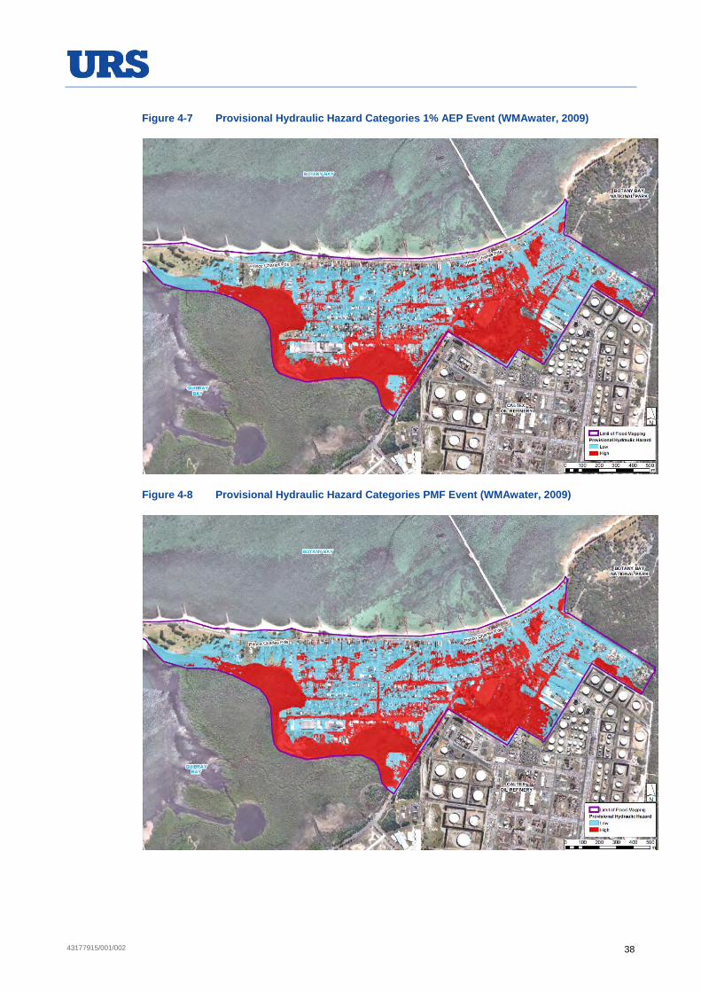
43177915/001/002 38
Figure 4-7 Provisional Hydraulic Hazard Categories 1% AEP Event (WMAwater, 2009)
Figure 4-8 Provisional Hydraulic Hazard Categories PMF Event (WMAwater, 2009)

43177915/001/002 39
The true hazard, which is a measure of the overall effects of flooding including threat to life, danger and difficulty in evacuating people and possessions and the potential for damage, social disruption and loss of production, was also assessed in a subsequent study in 2012 (WMAwater, 2012). The results are summarised in Table 4-1.
Table 4-1 Flood Hazard Classification (WMAwater, 2012)
Criteria Weight Comment
Rate of rise of floodwaters Medium The rate of rise in the catchment may lead to the Kurnell village being cut off rapidly, which would not allow time for residents to prepare.
Duration of flooding Medium The duration of the event will be a few hours and would not significantly increase the hazard. Post flood drainage will be slow.
Effective flood access High Roads within the catchment can be inundated and may restrict vehicular access during flood.
Size of the flood Low The hazard does not significantly increase with the magnitude of the flood. The Kurnell village may be cut-off for the duration of the flood.
Effective warning and evacuation times
High There is very little, if any, warning time. During the day residents will be aware of the heavy rain but at night (if asleep) residential and non-residential building floors may be inundated with no prior warning.
Additional concerns such as bank erosion, debris, wind wave action
High The main concern would be debris blocking culverts or pits. This is considered to have high probability to occur and thus of high impact.
Evacuation difficulties Low Given the quick response of the catchment, evacuation is not considered to be necessary and therefore is not significant.
Flood awareness of the community
Medium The flood awareness of the community is due to frequency and severity of nuisance flood.
Depth and velocity of flood water
Low Flow velocities and depths are flow
4.2.2.2 Site Flooding
Screening Assessment
The impacts of flood events on the Site were not directly assessed in the WMAwater study (2009) for the Sutherland Shire Council (SSC). The Site is generally elevated above the surrounding low lying areas on the western and northern boundaries, and the onsite bunding around petroleum products storage areas effectively increases the flood height that would need to be present for any interaction between petroleum products and flood waters to occur.
To better understand the likelihood of a flood event affecting the Site, a preliminary analysis of the flood risk was conducted considering the flood scenarios presented in the WMAwater study (2009) in the context of the known Site levels. The SSC commissioned flood modelling was used as the basis for this assessment, as these studies were the only data available.
This preliminary assessment was undertaken to determine the indicative flood risk to the Site by utilising the available flood depth and level information (refer to Figures 4-3 to 4-6)

43177915/001/002 40
provided in the Kurnell Township Flood Study Final Report (WMAwater 2009). Effectively boundary level flood levels/depth data was projected onto the Site. The topographic survey information available for the local area and Site was disjointed and varied in detail. Detailed level survey information, sufficient to develop contours, was available for the north western portion of the Site (in the vicinity of the wastewater treatment plant). For the remainder of the Site there was not enough information to create a model of the existing surface but surveyed spot levels were available to allow consideration of the potential for flooding within the Site.
This assessment involved projecting the available data on flood levels at the Site boundary from the SSC modelling study (WMAWater, 2009) for a 1% AEP event onto the Site. As discussed in Section 4.2.2.1, the peak flood levels within the modelling domain vary due to topography and drainage features and behaviour, and this can be seen at the boundary of the Site. Along most of the western boundary of the Site, the 1% AEP event peak flood level is about 2.82 m AHD, however, in the north west corner of the Site, near Gate 5, the peak level is about 4.25 m, and even higher in the north east corner. Three different flood levels for the same 1% AEP event were therefore selected to be applied to three separate parts of the Site boundary for this screening assessment. For each of these Site boundary sections, a Site area was selected to which the boundary flood level would be applied, considering the Site catchment and drainage arrangements, as well as the topography within the Site.
The flood level applied to corresponding Site areas for this assessment is shown in Figure 4-9 (which also contains Site spot levels for comparison purposes). The three areas and applied floods levels are:
Western and central part of the Site, 2.82 m AHD flood level (blue area in Figure 4-9, Catchment B, C and the south west part of Catchment A, shown on Figure A-3, Appendix A);
North east corner of the Site, 4.25 m AHD (orange area in Figure 4-9, part of Catchment A, shown on Figure A-3, Appendix A); and
Northern boundary and eastern part of the Site, 7.5 m AHD (corresponding to an approximate 3 m flood depth at the Site boundary) (red area in Figure 4-9, most of Catchment A shown on Figure A-3, Appendix A).
The three screening flood levels, mentioned above, were obtained by examining both the flood height and depth maps from WMAwater (2009). Where the land adjacent to the Site is lower than the Site, it is appropriate to use the flood level for screening purposes to consider flooding extent onto the Site, but where the adjacent land is higher, it may not be appropriate (e.g. if the Site is at 4 m AHD, but the adjacent land is at 7 m AHD and the flood level is 10 m AHD, the flood water depth adjacent the Site boundary is effectively only 3 m, rather than 6 m that would be assumed if the flood level was adopted rather than the depth).
The local topography is at its highest along the eastern boundary of the Site and gradually becomes lower to the north west of the Site, dipping towards Botany Bay. Therefore for the north western part of the Site the land immediately beyond the Site boundary is lower.

43177915/001/002 41
Figure 4-9 Site Spot Levels and Applied Flood Levels
Beyond the north-eastern corner of the Site however, the land slopes into the Site and is therefore higher beyond the boundary (within both Kurnell and the National Park) than at the Site boundary where a natural low point exists. At this location, a catchment drain has been constructed that carries stormwater runoff from the offsite areas to the north-west of the Site, into the Marton Park Wetland (refer to Figure A-3, Appendix A). In this area therefore, as discussed above, the flood depth at the Site boundary has been utilised to develop a flood level at the Site boundary, rather than directly extrapolating the flood level data shown in Figures 4-3 and 4-4.
Flood depths adjacent to the Site at the north eastern boundary are very coarsely mapped as 1.5 – 3 m. The depth of flooding presented in WMAwater (2009) is likely to be an over-estimate as close examination of the report suggests there may be a significant anomaly in the elevations that have been used in the flood modelling along the northern boundary. It is possible that the catchment drain along the north-eastern boundary has not been modelled correctly. The 3 m depth of water is most probably related to the catchment drain, and therefore adoption of this level as an extreme is considered to be overly conservative. Nevertheless in the absence of less coarse or alternate data, this level was adopted for this preliminary review. A level of 7.5 m AHD was applied to this area based on the approximate ground level of less than 4.5 m AHD in the north east corner of the Site.

43177915/001/002 42
Flood Projections
Detailed survey information was available for the north western part of the Site in the vicinity of the wastewater treatment plant (inset area shown on Figure 4-9). As discussed in Section 3.2.4, this is the area where some localised flooding has occurred following significant storm events. In this area, where more detailed level and contour information was available, a digital elevation model (DEM) was prepared in ArcGIS to interpolate the ground surface level between surveyed points, and the 1% AEP event flood level of 2.82 m across the surveyed area. No hydraulic modelling was carried out. The results of this work are shown in Figure 4-10.
Figure 4-10 shows that there is a relatively shallow depth of flooding within the Site near the intersection of Captain Cook Drive and Solander Street, which is consistent with experience of flooding in that area. The plan also shows that the area of flooding within the Site is limited and would not overtop any bunds within the surveyed area and would not affect any areas where demolition works are proposed.
Figure 4-10 Flood Projection (2.82 m AHD) on the North West of the Site
43177915/001/002 43
Permanent Mark (PM) levels were available in various locations throughout the Site, but not detailed contour information, other than in the aforementioned north west corner. These PMs were used to give an approximation of the ground levels where detailed survey data was not available. Consideration was also given to the level of bunds, so that the potential for overtopping by floodwaters could also be considered. PM levels were available to indicate bund heights in the north west of the Site, but not elsewhere. Hydrocarbon tanks in the western tank area typically had a bund height above ground level of at least 3 m.
Extrapolation of flood levels and depths, as described above, indicated that the adopted flood levels were below Site ground level at all locations on the Site, with the following exceptions:
Limited areas in the north west part of the Site, as shown in Figure 4-10;
Possibly some very minor flooding (<0.1 m depth) across the western boundary in the area immediately to the north of Gate 5; and
The Site area immediately across the north eastern boundary (area occupied by the first row of tanks only).
Data on the tanks bund heights along the north eastern boundary are not available, although typical Site bund heights may be of the order of 3 m. It is expected therefore that the existing bunding in this area would be sufficient to prevent interaction of flood waters with the storage tanks in a 1% AEP storm event, but based on the current data this cannot be stated conclusively. However the tanks along the north eastern edge of the Site would remain and would not be removed during the demolition works.
Flood Risk Category
Sutherland Shire Council (SSC) has planning controls relating to flood risk levels and requires that infrastructure standards and safety measures be suitable for the associated risk level. SCC has expressed the view that some of the Site may be classified in the medium risk category (no high risk). The medium risk category is defined by Council as the 1% AEP level plus 100 mm freeboard, plus 900 mm sea level rise (Phillippa Biswell, 5 April 2013, pers. comm.), which has been indicated by Council as corresponding to 3.6 m AHD (SCC has assumed a 1%AEP flood level of 2.6m on the western boundary of the Site rather than the 2.82 m adopted for this aforementioned assessment). This criterion was used to assess medium flood risk category areas on the Site.
The level of 3.6 m AHD was compared to ground level spot levels within the Site. All areas were assessed for flood risk and the only area that was identified as medium risk based on available ground level data was in the same area as shown in Figure 4-10 near the corner of Captain Cook Drive and Solander Street. A small area immediately near the intersection of Cook Street and Solander Street is also marginally below 3.6 m AHD and therefore in the medium risk category. As indicated previously, the product tank bunds in the medium risk area are all of a height well in excess of the nominated risk level. Tank bunds would not be removed as part of the demolition works.
4.2.3 Tsunamis
Tsunami risk profiles around the Australian coastline are represented by offshore tsunami hazard maps that have been prepared by Geosciences Australia, under its Probabilistic Tsunami Hazard Assessment (PTHA) program. This provides the likelihood and relative

43177915/001/002 44
tsunami amplitude at the 100 m depth contour around the coastline. This work focuses on the hazard arising from the main source of tsunami risk; subduction zone earthquakes, but does not consider other lower probability and less predictable tsunami risk factors such as volcanoes, asteroids, submarine landslides or non-subduction zone earthquakes. While the tsunami hazard maps provide a relative offshore tsunami hazard around Australia, the maps are not intended to determine the inundation extent, run-up, damage or other onshore phenomena that may result from a tsunami event (but could be used as the basis to derive this).
The Tsunami hazard for the offshore area adjacent to Kurnell, derived from the PTHA maps, is presented in Table 4-2. The information in Table 4-2, derived from the PTHA maps, indicates the maximum tsunami amplitude which could be expected at an adjacent offshore location (100 m depth) in any given year for a stated probability or chance. As discussed previously, the extent to which the approximate tsunami amplitudes provided in Table 4-2 may influence the Site has not specifically been assessed.
Table 4-2 Tsunami Hazard for the Offshore Region Adjacent to Kurnell
AEP Average Recurrence Interval ( Years)
Maximum Tsunami Amplitude ( Meters)1
1% 100 0.20
0.2% 500 0.60
0.10% 1000 0.80
0.05% 2000 1.10
0.02% 5000 1.6
1 Measured at 100 m depth contour
In order to more quantitatively assess the risk to the Site and potential impact arising from tsunamis, a detailed inundation model would be required for Botany Bay, including Quibray Bay, taking into account the detailed local bathymetry and topography. A detailed inundation model such as this would normally be prepared to consider the regional risk, rather than being specifically focussed on an individual site.
The NSW Office of Environment and Heritage (OEH) in conjunction with the NSW State Emergency Service (NSW SES) managed the NSW Tsunami Hazard Study, which, as part of the second stage of the project, included detailed tsunami inundation modelling of five areas along the NSW coastline, including Botany Bay/Kurnell (CAWCR 2013). High resolution digital elevation models were developed of each site. Earthquake scenarios were selected, corresponding to specific average recurrence intervals (ARI). Each site was modelled against 19 earthquake scenarios. The results of the inundation modelling of Botany Bay are shown in Figure 4-11 (Hanslow, et al, 2013).

43177915/001/002 45
Figure 4-11 Tsunami Inundation Modelling of Botany Bay (Hanslow, et al, 2013)
As indicated by the modelling results (refer to Figure 4-11), even during a 10,000 ARI tsunami event, inundation of the Site is not predicted. The closest inundated area in proximity to the Site is to the north west on the northern side of Captain Cook Drive. The model predicts a maximum inundation height of about 5 m AHD. The modelling conservatively assumed the highest astronomical tide (HAT) level as the baseline for inundation. It does not assume, however, that the tsunami coincides with storm event flooding (Hanslow, et al, 2013).

43177915/001/002 46
4.3 Impact Assessment
4.3.1 Demolition and Post Demolition Phases
The risk profile of the Site with respect to the ability to accommodate high rainfall events and/or broader flooding events would not significantly change from that which currently exists during and following the demolition works. Existing tank farm bunds would be left intact, even if the tank within it is removed. The refinery process units and some other infrastructure would be removed but the existing ground levels would essentially be the same. The temporary works required at Silver Beach to remove the cooling water pipeline from the beach profile would include the reinstatement and rehabilitation of the dune and beach following the demolition works as detailed in Appendix G2 Marine Ecology and Appendix H Coastal Processes of the SEE. As such, there would be no significant change in the flooding risk profile.
As indicated in Section 4.2.2, a small section of the north west of the Site is classified as medium flood risk, based on SSC criteria. This area has been subject to some localised flooding in the past (as discussed in Section 3.2.4), in response to which Caltex has assessed, identified, and is in the process of implementing, a range of improvement measures, including:
implementation of the Stormwater Management Plan (described in Section 3.2.6), which is in part specifically focussed on addressing flooding in this area;
completion of a review of all electrical equipment, which had identified the need to increase the height of a substation and switch room in the medium risk area, which has now been implemented.
modifications to the wastewater treatment system and infrastructure that would occur as a consequence of the refinery shutdown.
The SMP will improve the ability of the Site to handle stormwater and as a result will reduce the risk of catchment flooding. The monitoring component of the SMP will inform a stormwater model, which in turn will provide the basis for identifying future stormwater management improvements, where required. It has also been identified in Section 4.2.2, that some further consideration of the flood risk along the north eastern boundary is required. The implementation of the SMP and further changes to the stormwater system following completion of the conversion works and following future remediation works would result in changes to flood risk on the Site. As such, Caltex will reassess the flood risk during the remediation works to ensure that future flood risks to the Site are understood and appropriately managed.
4.3.2 Climate Change
The NSW Government, Floodplain Development Manual – the Management of Flood Liable Land (Department of Infrastructure, Planning and Natural Resources, 2005) requires the consideration of climate change as part of all flood studies.

43177915/001/002 47
Sea Level Rise
Sea level rise is a continuous rising of the water level of the oceans and estuaries. The NSW Sea Level Rise Policy Statement (NSW Government 2009) suggests that sea level may rise by 0.4m by 2050 and 0.90m by 2100. The tide levels will also rise accordingly, which will affect the natural processes responsible for shaping the coastline. The increased sea levels can heavily affect the capacities of the drainage systems discharging to seas and estuaries.
Tidal flooding is influenced by the height and timing of tides and tidal surges. Tidal surges are caused by regional weather conditions such as pressure systems, wind direction and speed and local bathymetry. The combination of tidal surge and high rainfall in a catchment would produce the worst flooding. However, this coincidence is considered to be unlikely.
Tidal locking from raised tailwater conditions can extend flooding risks well beyond the immediate areas of the estuaries causing tidal inundation by saltwater and reducing the ability of low lying areas to drain effectively. Flooding from the sea and tidal water can be more severe than flooding from water courses due to the hazards associated with potential flood velocities and depth.
The Kurnell Township Flood Study (2009) conducted sensitivity analysis of the following climate change scenario:
Sea level rise:
Low: +0.18m
Medium: +0.55m
High: +0.91m
Peak rainfall volume:
Low: +10% rainfall
Medium: +20% rainfall
High: +30% rainfall
Twenty two (22) scenarios were considered for the assessment of potential impacts of climate change on sea level rise and catchment flooding (due to increase in rainfall intensity) independently, as well as the combined effects. The sensitivity of both 5% and 1% AEP events to climate change have been modelled to provide an indication of the magnitude of impacts for both smaller, more frequent flood events as well as major events.
The report concluded that the combination of an ocean flood event with sea level rise has the most significant impact on flooding in Kurnell. It was estimated that the flood levels may increase as much as 900 mm in areas close to Quibray Bay.
The potential storm tide extent is shown in Figure 4-12. This figure shows that it is likely that the dominant flooding mechanism in some areas of Kurnell may shift from catchment flooding to ocean flooding (WMAwater, 2009).

43177915/001/002 48
Figure 4-12 Potential Storm Tide Extents (WMAwater, 2009)
In addition, the influence of varying tailwater conditions on the design flood behaviour were also assessed for the 5% and 1% AEP design storm events, with a tailwater level of 0.6 m. Then the sensitivity analyses were carried out for 5% and 1% AEP with a 1.7 m AHD (1% AEP tide) and a 2.0 mAHD (extreme tide); and 0.9 mAHD (high spring tide) and 1.7 m AHD tailwater level respectively. It was concluded that the impact on flood levels is generally greater for the 20% AEP event, as tidal flooding becomes the main cause of flooding adjacent to Quibray Bay, while the flooding from rainfall is still a significant component for 1% AEP event (WMAwater, 2009). This assessment was not extended by WMAwater to within the Site boundary.
Climate change induced sea level rise could potentially lead to an increased flooding risk in the part of the Site adjacent to Captain Cook Drive that has already been identified as having an elevated flood risk. The demolition works would not result in any significant changes to this area; however the Waste Water Treatment Plant (WWTP) that occupies this area would ultimately be modified after the conversion is complete. This modification would address the changes in wastewater load and characteristics due to the conversion into a terminal (and considering the shutdown of the refinery). Changes, required to make this area and the infrastructure in it less susceptible to flooding, will be considered during the modification of the WWTP.
4.4 Summary
The studies conducted by Sutherland Shire Council indicated that the areas around the Site are susceptible to flooding from both rainfall and tidal inundation, and this would be exacerbated by climate induced sea level rise. The impacts of the assessed flood events on the Site were not directly assessed.

43177915/001/002 49
The Site is generally elevated above the surrounding low lying areas on the western and northern boundaries, and the onsite bunding around petroleum products storage areas effectively increases the flood height that would need to be present for any interaction between petroleum products and flood waters to occur.
The demolition works are not expected to change the flood risk profile on the Site nor would it change the ability to accommodate high rainfall events and/or broader flooding events from that which currently exists. Based on the studies conducted by the Sutherland Shire Council, the capacities of the Site drainage systems may be constrained by high tailwater conditions in particular.
The implementation of the SMP and further changes to the stormwater system following completion of the Project and following the demolition works would result in changes to flood risk on the Site. As such, Caltex will reassess the flood risk as part of its ongoing review of stormwater management on the site, through the SMP, to ensure that any future flood risks to the Site are understood and appropriately managed.
Due to the short duration of the demolition works, sea level rise is not considered likely to impact upon these works.


43177915/001/002 51
5 OILY WASTE GENERATION AND MANAGEMENT
5.1 Introduction
This section presents an overview of the oily water generation and management at the Site, including a description of the existing Oily Water Management System (OWMS) outlining the:
existing oily water source and quality;
wastewater treatment; and
discharge locations and criteria.
The oily water management system for the operation of the conversion works has yet to be finalised. There will be a significant reduction in the oily water load at the Site arising from the shut-down of the refinery, which will be a major influence the ultimate oily water management arrangements, but this is outside the scope of this assessment. Caltex has reached an “in principle” agreement with NSW EPA that, in consultation with the EPA, a PRP condition would be developed and included in the terminal EPL that would apply when the terminal is operational. The process agreed with the EPA would:
characterise the terminal wastewater stream;
identify and assess terminal wastewater management options;
recommend preferred options; and
confirm applicable EPL conditions, including those related to discharge points, quality and monitoring.
Given that the demolition works would proceed following the deinventorisation and cleanout of redundant plant and infrastructure, it is not anticipated that demolition works would generate significant oily water/wastewater streams or load.
5.2 Existing Environment
5.2.1 Background
The Site’s OWMS (also referred to as the oily water sewer system) collects process effluent and rainfall runoff from areas of the Site where there is potential for interaction of water streams with petroleum products. Oily water is collected in the Site’s oily water sewer system and is transferred to the wastewater treatment plant. Treated effluent is discharged to the Tasman Sea via the Yena Gap outfall under conditions of the Site EPL.
5.2.2 Wastewater Sources
Sources of oily water discharged to the OWMS include the following:
stormwater runoff within tank bund areas, near process units and pump slabs;
any fuel released from any of the storage tanks or their associated piping which is contained within the bunded area surrounding the tank;
any firewater used in combating a fire which is contained in the bunded areas;

43177915/001/002 52
hydrocarbon contaminated groundwater from groundwater remediation system;
landfarm;
tank dewatering;
tank washing;
ballast water;
pipeline wash water;
slops from Banksmeadow;
equipment wash pads; and
stormwater that collects in the former CLOR oily water sewer system.
Oily water generated within bund areas is drained to the Site oily water sewer via a manual drain valve. These valves are closed under normal operating conditions, thereby retaining any released fuel and impacted water within the bunded area. Oily water accumulated within the bunded area is released in a controlled manner to the OWMS, in accordance with Site standard procedures.
5.2.3 Wastewater Treatment Plant
Oily water is treated in the Site’s oily water Waste Water Treatment Plant (WWTP), which includes a biotreator process.
Capacity and Feed Wastewater
The “operational maximum treatment capacity” for the biotreator wastewater treatment plant is notionally 600 kL/h, with a supplementary wastewater treatment system that has a capacity of approximately 1,000 kL/h (including all treatment steps except biotreator). However, the operational maximum treatment capacity may change depending on the number of healthy organisms in the biotreator WWTP.
Treatment Process
The Site WWTP utilises physical, chemical and biological treatment to treat the oily water. The main processes applied in the WWTP are:
equalisation in the retention/surge tank and equalisation tank;
aerobic biological treatment; and
clarification (i.e. sedimentation).
Some chemicals may be applied in the process to assist in treatment, such as the addition of coagulants to aid settling, and alkali reagents for neutralisation (caustic dosing).
Oily water discharged to the OWMS is sent to the WWTP for treatment by the biotreator, or alternatively is transferred to a diversion or equalisation tank for storage and treatment in the biotreator at a later time.

43177915/001/002 53
The biotreator WWTP also has a biotreator bypass system. Bypass of the WWTP can occur only when excess wastewater resulting from stormwater falling on the Site within the oily water sewer catchment cannot be treated by the WWTP due to plant maintenance or operating problems. The objective is to ensure that the WWTP is operating at full capacity before wastewater is diverted to the supplementary wastewater treatment system, which comprises oil-water separators and an induced air flotation (IAF) system.
Under the current EPL conditions, all wastewater must be treated using the biotreator WWTP or the oil-water separators/IAF system prior to discharge at Yena Gap. The main WWTP can only be bypassed to the supplementary oil-water separator/IAF system when:
the influent flow rate exceeds the biotreator operational maximum treatment capacity and both the effluent diversion tank and the equalisation tank are more than 85% full;
the transfer capacity of the diversion pumps and the equalisation tank feed pumps are insufficient to deal with the wastewater flow;
the biotreator WWTP is offline for essential maintenance; or
an assessment of the pump capacity of the bypass pumps is being conducted to check maximum pump capacities and equipment availability.
Whenever wastewater bypasses the biotreator WWTP and is discharged at Yena Gap, the flow rate through the biotreator WWTP must be maintained at its maximum treatment capacity, unless the biotreator WWTP is off-line for essential maintenance. Any reduction in flow rate must be recorded and reported to the EPA within 7 days.
5.2.4 Treated Wastewater Discharge
Treated effluent from the WWTP is discharged to the Tasman Sea via the Yena Gap outfall.
The Yena Gap is shown on Figure A-2 (Appendix A). The outfall consists of approximately 2.4 km of 600 mm diameter cement lined steel pipe. The diffuser outlet is located approximately 100 m offshore, at a water depth of about 6 m.
The Site EPL requires that treated wastewater discharge quality monitoring be conducted at Point 27 to determine compliance with concentration limits specified for discharge Point 2. The discharge limit for Point 2, and monitoring frequency and sampling method for Point 27, as outlined in the EPL as well as the Annual Return Report and Yearly Monitoring Data Summaries for Yena Gap for years 2010 - 2014, is presented in Table C-2 and Table D-1 in Appendix C and Appendix D of this report, respectively.
5.3 Impact Assessment
5.3.1 Sources and Load
During the demolition works, the refinery process area would be disconnected from the OWMS and some of the infrastructure would be removed from beneath the refinery process units. The OWMS in remaining areas including the eastern and western tank farm areas would be kept in service throughout the conversion works, and stormwater runoff from these bunded areas would continue to be routed to WWTP, regardless of the removal of some of the tanks. Tank bunded areas and tank water drains would remain largely unchanged and flow

43177915/001/002 54
from these areas would continue to be treated in the WWTP. The Site would continue to handle ballast and pipe wash water, though the quantities may vary from those currently handled.
In addition, with the shutdown of the cooling water system, the intermediate sewer system would be directed to the OWMS. This potential increase in load on the system would be more than offset by the significant reduction in load arising from the shutdown of the refinery.
5.3.2 Treatment
Following the shutdown of the refinery during the conversion works, the overall oily water volume and contaminant load would reduce substantially. This would be slightly offset by an increase arising from the redirection of the intermediate sewer system from the cooling water system to the OWMS during and after the demolition works. As discussed in the conversion works EIS, the WWTP would continue to operate under the existing EPL until the conversion works are completed, at which time it would be renegotiated with the EPA.
5.3.3 Disposal
The treated wastewater effluent generated during the demolition works and following the completion of demolition, would continue to discharge to Yena Gap in accordance with the current EPL conditions. These conditions may be revised following the process outlined in Section 6.3.2.

43177915/001/002 55
6 OTHER WASTE SYSTEMS
6.1 Introduction
This section provides an assessment of the impacts of the demolition works on the other water systems currently present at the Site. It should be noted that the demolition works would have relatively limited interaction with other water systems. The assessment provides:
descriptions of the existing water supply and usage arrangements;
an assessment of the water supply and usage requirements during the demolition work;
descriptions of the existing domestic wastewater treatment;
an assessment of the domestic wastewater quantity and quality impacts, with reference to demolition work;
descriptions of the existing cooling water system; and
assessment of the interaction with and impact of demolition works with the cooling water system.
6.2 Water Supply and Usage
6.2.1 Existing Environment
Water Supply
Currently the Site’s potable water is supplied by Sydney Water from the Cronulla Main. This water supply supports the firewater system, as well as the domestic and process water systems.
Water Licensing and Sharing Plans
The Water Management Act 2000 (WM Act) governs the issue of water access licences and approvals for those water sources (rivers, lakes, estuaries and groundwater) in New South Wales where water sharing plans have commenced. The Site is located within the area covered by the commenced Water Sharing plan entitled the ‘Greater Metropolitan Region Groundwater Sources’ 2011.
The WM Act creates:
mechanisms for protecting and restoring water sources and their dependent ecosystems;
improved access rights to water; and
partnership arrangements between the community and the Government for water management.
The WM Act defines an aquifer interference activity as that which involves any of the following:
the penetration of an aquifer,
the interference with water in an aquifer,
the obstruction of the flow of water in an aquifer,

43177915/001/002 56
the taking of water from an aquifer in the course of carrying out mining or any other prescribed activity, and
the disposal of water taken from an aquifer in the course of carrying out mining or any other activity prescribed by the regulations.
The NSW Aquifer Interference Policy applies to any project or activity involving any of the above and a water licence is required whether water is taken for consumptive use or whether it is taken incidentally by the aquifer interference activity. The Policy recognises that even where there is no take of water, aquifer interference activities can still affect the functioning of aquifers which can impact water users and dependent ecosystems.
Across the Caltex Site, groundwater is likely to be encountered in excavations deeper than 1.4 m below ground level (mbgl).
Excavations associated with the demolition works may extend to 2 mbgl in depth. Therefore groundwater is expected to be encountered. However, generally, minor temporary dewatering activities that are estimated to take less than 3 ML/yr of groundwater will generally not require a licence or approval from NOW. Therefore regular consultation with NSW Office of Water (NOW) would occur to ensure that permitting requirements are met as demolition proceeds.
This is further discussed in Chapter 9 Soil, Groundwater and Contamination of the SEE.
Water Usage
In 2010/11, the Site consumed approximately 6 ML of potable water per day for process operations and 1 ML per day for amenities. At this time, the refinery was in full operation (though the CLOR was no longer operating) and the Site workforce was up to a maximum of approximately 1,385 persons. As the conversion works progress, the process and amenity related water usage will decline.
The refinery will have shut down by the end of 2014, and at that stage, a substantial portion of the potable water usage as process water (about 6 ML/d in 2010/11) would have ceased. The deinventoring and cleaning phase will require potable water, but a substantially lower amount than required by the refining process.
The domestic type water usage (drinking, toilets, showers, lunchroom, etc) would decline significantly with the decrease employee and contractor workforce. The cumulative number of workers present on the Site for the period 2015 to 2017 (which includes conversion and demolition works) is predicted at a maximum of about 410 persons. Potable water consumption for amenities is approximately proportional to staff levels, and the potable consumption for amenities usage would be approximately 300 KL/d.
The predicted overall potable water usage (including for firewater usage, discussed in the next sub-section) post conversion works, as discussed in the conversion works EIS, is predicted to be less than 10% of the 2010/11 usage, i.e. less than 700 kL/d. This equates to the predicted water usage during the demolition works.
It has been estimated that a maximum of 1ML per day would be required for the ongoing operation of the terminal.
43177915/001/002 57
Firewater
The Site has a comprehensive fire protection system, which (amongst many other features) includes an extensive fire water ring main and fire hydrant system. Two firewater storage tanks at capacity of 8 ML each are available from the north and south (R4Risk, 2012).
The Site’s firewater has been supplied by both municipal potable water and seawater drawn from the cooling water system, but will be supplied by the potable water supply only following shutdown of the cooling water system. Firewater usage (municipal water) estimate from the Power Plant Meters for period May 2010 to April 2011 was about 127 ML (~350 kL/d), or about 6% of the overall potable water usage. This will reduce significantly following the shut down of the refinery in the second half of 2014, but some firewater will still be required for the terminal.
This usage is not normally for actual fire incidents, rather it is the consumption associated with pump, hydrant, monitor and other system testing that is regularly conducted, as well as fire training conducted on the fire training ground and elsewhere on the Site.
6.2.2 Impact Assessment
Demolition Phase
Water supply would be required during the demolition works for a range of uses including:
dust suppression;
general cleaning; and
general workforce amenities.
This water would be potable water supplied by Sydney Water. Existing supply infrastructure would be utilised. Some onsite potable water, including firewater, supply infrastructure, particularly in the refinery process area, would be removed during demolition works. The firewater system would be supplied by potable water only with no backup cooling water available. The overall Site water demand during the demolition works would be significantly lower than current usage, but marginally higher than post conversion works usage, of the order of 1 ML/d.
The demolition works would result in peak increase of approximately 230 employees and contractors at the Site. This corresponds to about 173 kL/d potable water usage above the amount anticipated for when conversion works are complete.
6.3 Domestic Wastewater
6.3.1 Existing Environment
Sources of Domestic Wastewater
Domestic wastewater, also referred to as sewage, sanitary effluent, and septic effluent, comprising grey and black water wastewater streams, is generally derived from toilets and showers and other domestic water uses across the Site.

43177915/001/002 58
Septic Effluent Quantity
The discharge volume of sewage is not normally metered or otherwise measured. Its volume was last estimated in 2001, as reported in the Septic Effluent Study conducted for the Site under EPL Condition PRP U6 Septic Effluent Study. The total annual domestic wastewater load in 2001 was about 52 ML (determined over the month of November 2001 and extrapolated to approximate annual contributions). At that time, domestic wastewater was discharged from the Site via the Yena Gap and Tabbigai Gap outfalls (26.3 ML/a and 25.5 ML/a respectively).
Since then, the Site has redirected domestic wastewater from the outfalls to the Sydney Water sewerage system. The load would have reduced significantly since 2001, as the CLOR is no longer operational and Site staff numbers have reduced.
Domestic Wastewater Quality
Domestic wastewater quality is not routinely monitored. The most recent assessment of quality, conducted in 2001 as part of the Septic Effluent Study, did not indicate variation from typical domestic wastewater quality.
System Description
The Site domestic wastewater system generally consists of a sewage collection tank at generation locations. Each tank is fitted with a duty and standby sewage pump. The sewage tanks are equipped with level switches (Level Switch High (LSH) and Level Switch High-High (LSHH)) to detect the level of sewage present. When the sewage level rises to a predetermined level, the pump is initiated to lift the sewage through a rising main from where the sewage is discharged into the Sydney Water Vacuum Pit.
Destination
The Site domestic wastewater is discharge to the Sydney Water’s sewerage system for treatment at the Cronulla Treatment Plant.
6.3.2 Impact Assessment
The demolition works would utilise the existing domestic wastewater infrastructure.
Some sewerage pipelines would be removed during the demolition works, between demolished units and Site main sewers.
The demolition workforce would be approximately one third of that present on the site in 2010/11. This will drop by a further 30% by the completion of conversion works. Reductions in domestic wastewater volumes would be approximately proportional to workforce level reductions. As such, the existing domestic wastewater infrastructure has adequate capacity to accommodate waste generated by the demolition works.
There would be no other significant changes to domestic wastewater management on the Site arising from the demolition works. It would continue to be pumped to the Sydney Water sewerage system for treatment at the Cronulla Treatment Plant.

43177915/001/002 59
6.4 Cooling Water System
6.4.1 Existing Environment
Background
The Site’s cooling water system, incorporating the intermediate sewer system, has been used for the removal of excess heat in condensers and coolers. The cooling water system has also been used as a source of water for fire-fighting.
Cooling Water Source
The Site’s cooling water system utilises seawater which is pumped from Botany Bay by any of the five electric driven pumps located at the pumphouse on the Kurnell Wharf. This seawater is pumped to two saltwater tanks. The tanks are equipped with remote level indication and level alarms and provision for local and remote starting and stopping of the pumps as required.
The Site’s existing EPL conditions requires total volume monitoring be conducted at Point 33. The volumetric flow rate monitoring frequency and sampling method adopted as outlined in the EPL is presented in Table C-1 in Appendix C.
The total volume of seawater taken from Botany Bay which was used in the cooling water system, as reported in the Annual Return Report for period 2010-2011 and 2011-2012, was on average, 270 ML/d, varying between 155 ML/d and 308 ML/d, below the allowable EPL limit of 400 ML/d discharged at identification point 1. Discharge volumes in 2012-2013 and 2013-14 were reported in Caltex’s published yearly summaries of monitoring data. Discharge volumes from Point 33 remained within the licence limit, with an average across both years of around 254 ML/d, varying between 136 ML/d and 308 ML/d.
Cooling Water Discharge
Cooling water is discharged into Botany Bay at Silver Beach via an outfall pipeline on the western side of the Kurnell Wharf. The cooling water outfall pipeline leaves the WWTP and travels through the western right of way.
Cooling water leaving the refinery process units has been separated into two streams – clean and intermediate cooling water effluent, depending on its potential to contain product in the event of a leak or other upset, e.g. manual diversion of impacted stormwater to the intermediate sewer in Catchment B.
With the closure of the refining operations at the Site, the cooling water system would cease operation. Consequently the daily cooling water pumping and effluent discharge to Botany Bay will also cease. This has been discussed in the conversion works EIS, (URS, 2013).
The cooling water outfall pipeline would be sealed at Prince Charles Parade, with the section from there to Botany Bay (including the outfall) left insitu.

43177915/001/002 60
6.4.2 Impact Assessment
Whilst some of the infrastructure involved in the cooling water system would remain in place following the demolition works, the demolition works would include the removal of the cooling water outlet line running from the Site to the western right of way, and the removal of two cooling water intake lines running from Kurnell Wharf though the eastern right of way. No significant surface water impacts are expected to arise from the removal of the cooling water intake infrastructure or from the outfall infrastructure left in place.
The intermediate sewer system, which formerly discharged to the cooling water system, would remain in place but would be directed to the oily water system, as discussed in Section 5.

43177915/001/002 61
7 REFERENCES
Caltex 2011, Stormwater Management Plan Environment Protection Licence #837 Condition U10. PRP U24., Caltex Refineries (NSW)Pty Ltd, NSW
Centre for Australian Weather and Climate Research (CAWCR, 2013), Uslu, B. & Greenslade, D., Validation of Tsunami Warning Thresholds Using Inundation Modelling, CAWCR Technical Report No. 062, June 2013, <http://www.cawcr.gov.au/publications/technicalreports/CTR_062.pdf>
DIPNR 2004, Proposal by Caltex Refineries (NSW) Pty Ltd to Upgrade the Existing Refinery, Kurnell Peninsula, in the Sutherland Local Government Area, Assessment Report for Development Application DA-30-2-2004-I Pursuant to Section 80 of the Environmental Planning and Assessment Act, 1979, Department of Infrastructure, Planning and Natural Resources, NSW
EPAa 2012, Caltex Refineries (NSW) Pty Ltd Environment Protection Licence 837, New South Wales Environment Protection Authority, NSW.
EPAb 2012, Caltex Refineries (NSW) Pty Ltd Licence Summary, New South Wales Environment Protection Authority, viewed 14 November 2012 < http://www.environment.nsw.gov.au/prpoeoapp/Detail.aspx?instid=837&id=837&option=licence&searchrange=general&range=POEO licence&prp=no&status=Issued>
Garber, S., Treloar, D., Beadle, C., Hanslow, D., Opper, S., Validation of the Tsunami Modelling along the NSW Coast, Proceedings of the 20th NSW Coastal Conference, 2011 <http://www.coastalconference.com/2011/papers2011/Sean%20Garber%20Full%20Paper.pdf
Geoscience Australia 2012, Offshore Tsunami Hazard for Australia, Geoscience Australia, viewed 19 November 2012 < http://www.ga.gov.au/hazards/tsunami/offshore-tsunami-hazard-for-australia.html#>
GHD 1992, CRL/ALOR Stormwater Management Study Draft Report, R1847.CF.JRL. 214/024058/00, Gutteridge Haskins & Davey Pty Ltd, NSW.
GHD 1993, Stormwater Disposal Investigation Draft Report, 214/024205/00 2898, Gutteridge Haskins & Davey Pty Ltd, NSW
Greater Metropolitan Region (Map 18). Found at the following webpage: http://www.planning.nsw.gov.au /en-us/planningyourregion /coastalprotection/ metropolitanregioncoastalzonemaps/ greatermetropolitanregionmap18.aspx
Hanslow, D., Andrews, F., Garber, S., Treloar, D., Beadle, C., Opper, S., Davies, B., Frazer, A., Greenslade, D., Horspool, N., and Kuster, N., (Hanslow, el al, 2013), Progess Towards and Understanding of Tsunami Risk in NSW, Proceedings of the NSW Coastal Conference, November 2013, < http://www.coastalconference.com/2013/papers2013/David%20Hanslow%20Full%20Paper.pdf
Landcom 2006. The Blue Book - Managing Urban Stormwater: Soils and Construction, 2004. (Construction Phase)

43177915/001/002 62
National Working Party on Acid Sulphate Soils 2000, National Strategy for the Management of Coastal Acid Sulphate Soils, National Working Party on Acid Sulphate Soils, Wollongbar Agricultural Institute, Wollongbar.
Office of Environment & Heritage 2013. Vegetation Mapping for the Sydney Metropolitan Area Version 2 (http://www.environment.nsw.gov.au/research/vegetationinformationsystem.htm)
R4Risk 2012, Kurnell Refinery Terminal Conversion Safety Study, Reference Number 107-19, Release 1, R4Risk Pty Ltd, Victoria
SMCMA 2007, Modelling the Catchments of Botany Bay, Sydney Metropolitan Catchment Management Authority, NSW.
SMCMA 2011, Botany Bay & Catchment Water Quality Improvement Plan, Sydney Metropolitan Catchment Management Authority, NSW.
Sutherland Shire Council 2012, Record of Proceedings for the Meeting of the Kurnell Township Floodplain Risk Management Committee of Sutherland Shire Council, Sutherland, File Number: GO/06B/301545, Sutherland Shire Council Business Paper and Community Directory Website, viewed 30 October 2012, < https://sscebp.ssc.nsw.gov.au/ebp/web/webpapr.nsf>
Underwood, A. J., Morrisey, D. J. and Howitt, L. 1991, Environmental Sampling at the Caltex 72” Outfall (Botany Bay, NSW) Final Report, the Institute of Marine Ecology, University of Sydney, NSW.
URS 2000, Ecological Risk Assessment of the Caltex Refinery Cooling Water System Discharge to Botany Bay - Problem Formulation and Preliminary Risk Characterisation Report, URS Australia Pty Ltd, NSW.
WMAwater 2009, Sutherland Shire Council Kurnell Township Flood Study, Final Report, May 2009.
WMAwater 2012, Sutherland Shire Council Kurnell Floodplain Risk Management Plan, Final Study, April 2012.

43177915/001/002 63
8 LIMITATIONS
URS Australia Pty Ltd (URS) has prepared this report in accordance with the usual care and thoroughness of the consulting profession for the use of Caltex Australia Limited and only those third parties who have been authorised in writing by URS to rely on this Report.
It is based on generally accepted practices and standards at the time it was prepared. No other warranty, expressed or implied, is made as to the professional advice included in this Report.
It is prepared in accordance with the scope of work and for the purpose outlined in the contract dated 25 July 2012.
Where this Report indicates that information has been provided to URS by third parties, URS has made no independent verification of this information except as expressly stated in the Report. URS assumes no liability for any inaccuracies in or omissions to that information.
This Report was prepared between 16 June 2014 and 8 August 2014 is based on the information reviewed at the time of preparation. URS disclaims responsibility for any changes that may have occurred after this time.
This Report should be read in full. No responsibility is accepted for use of any part of this report in any other context or for any other purpose or by third parties. This Report does not purport to give legal advice. Legal advice can only be given by qualified legal practitioners.
To the extent permitted by law, URS expressly disclaims and excludes liability for any loss, damage, cost or expenses suffered by any third party relating to or resulting from the use of, or reliance on, any information contained in this Report. URS does not admit that any action, liability or claim may exist or be available to any third party.
It is the responsibility of third parties to independently make inquiries or seek advice in relation to their particular requirements and proposed use of the site.


43177915/001/002
APPENDIX A LIST OF FIGURES
Figure A-1 Site Layout and Proposed Works
Figure A-2: Site Setting and Surrounding Environments
Figure A-3: Existing Stormwater Catchment Areas and Discharge Points


Figure:
Rev. A4
A-1
CALTEX (REFINERIES)NSW PTY LTD
This
drawi
ng is
subje
ct to
COPY
RIGH
T.
/
A
0 200 400100Meters
Whilst every care is taken by URS to ensure the accuracy of the digital data, URS makes no representation or warranties about its accuracy, reliabil ity, completeness, suitabil ity for any particular purpose and disclaims all responsibility and liability (including without limitation, liability in negligence) for any expenses, losses, damages (including indirect or consequential damage) and costs which may be incurred as a result of data being inaccurate in any way for any reason. Electronic files are provided for information only. The data in these files is not controlled or subject to automatic updates for users outside of URS.
Gate 5
KURNELL
Continental Carbon Pipeline
Fuel Pipelines &Cooling Water Intake
Right of WayCooling Water OutletRight of Way
Waste WaterTreatment Plant
WesternTanks Area
RefineryProcess Units
EasternTanks Area
PATH: T:\JOBS\43177915\Workspaces\
FILE NO: 43177915.023
DRAWN: STB/SS APPROVED: WM DATE: 20/10/2014
Coordinate System: GDA 1994 MGA Zone 56Projection: Transverse Mercator
Datum: GDA 1994Units: Meter
SITE LAYOUT AND PROPOSED WORKS
FOR DEMOLITION
LegendDemolition Works Area
The Site
Caltex Land Ownership
Pipeways where Works will be Required
Proposed Demolition Works
Proposed Eastern Tank Demolition Area
Underground Pipelines to be Removed
Source: Aerial Imagery - Nearmap 2014
KURNELL REFINERYCONVERSION MODIFICATION

Figure:
Rev. A4
A-2
CALTEX (REFINERIES)NSW PTY LTD
This
drawi
ng is
subje
ct to
COPY
RIGH
T.
/
B
0 500 1,000250Meters
Whilst every care is taken by URS to ensure the accuracy of the digital data, URS makes no representation or warranties about its accuracy, reliabil ity, completeness, suitabil ity for any particular purpose and disclaims all responsibility and liability (including without limitation, liabil ity in negligence) for any expenses, losses, damages (including indirect or consequential damage) and costs which may be incurred as a result of data being inaccurate in any way for any reason. Electronic fi les are provided for information only. The data in these files is not controlled or subject to automatic updates for users outside of URS.
B o t a n y B a y
MartonPark
Towra PointNature Reserve
Kamay Botany BayNational Park
Bonna Point Reserve
Kamay Botany BayNational Park
KURNELL
Caltex Refinery (Kurnell)
Ü
Captain CooksLanding Place
Ü
Desalination Plant
Weeney Bay
Botany Bay
TasmanSea
QuibrayBay
Ü
KurnellSubstation
Ü
Kurnell Wharf
Ü
ContinentalCarbon Australia
Ü
YenaGap
Bate Bay
Silver Beach
Source: Esri, DigitalGlobe, GeoEye, i-cubed, Earthstar Geographics, CNES/Airbus DS,USDA, USGS, AEX, Getmapping, Aerogrid, IGN, IGP, swisstopo, and the GIS UserCommunity
PATH: T:\JOBS\43177915\Workspaces\43177915.024.mxd
FILE NO: 43177915.024
DRAWN: STB APPROVED: RO DATE: 20/10/2014
Coordinate System: GDA 1994 MGA Zone 56Projection: Transverse Mercator
Datum: GDA 1994Units: Meter
SITE SETTING ANDSURROUNDING ENVIRONMENT
LegendCaptain Cook Drive
Demolition Works Area
The Site
Caltex Land Ownership
Minor Roads
Towra Point Aquatic Reserve ^
National Park
Towra Point Nature Reserve
Captain Cook Dr
Sir Jo seph Banks D r
Source: Aerial Imagery from Bing Maps © 2010 Microsoft Corporation and its data suppliers. Office of Environment and Heritage (OEH)
Map compiled using MapInfo StreetPro data. © 2011 MapInfo Australia Pty Ltd and PSMA Australia Ltd.
KURNELL REFINERYCONVERSION MODIFICATION

Figure:
Rev. A4
A-3
KURNELL REFINERYCONVERSION MODIFICATION
CALTEX (REFINERIES)NSW PTY LTD
This
draw
ing is
subje
ct to
COPY
RIGH
T.
/
A
0 200 400100Metres
Whilst every care is taken by URS to ensure the accuracy of the digital data, URS makes no representation or warranties about its accuracy, reliabil ity, completeness, suitabil ity for any particular purpose and disclaims all responsibility and liability (including without l imitation, liabil ity in negligence) for any expenses, losses, damages (including indirect or consequential damage) and costs which may be incurred as a result of data being inaccurate in any way for any reason. Electronic files are provided for information only. The data in these files is not controlled or subject to automatic updates for users outside of URS.
!A
!A
!A
!A
!A
!A!A
!A
!A!A
!A !A !A
kj
kj
kj
kjkjkj
kj
kj
KURNELL
!
Kurne ll W ha rf
!
Natural Retention Area
!
Natural Retention Basin
!
Quibray Bay StormwaterRetention Basin
!
(Currently Isolated)
Sir Joseph Banks Dr
!
Pump Station
Pipeway B
Pipeway A
Mai n
Pi pew
ay
!
Catchment G Drain
!
Pump Station
!
Manhole156
!
Discharge from Caltex owned portion of Marton
Park Wetland to wider wetland
! StormwaterSyphon Pit
! StormwaterTrench
! StormwaterTrench
!
Caltex owned landoutside of refinery
Captain Cook Dr
PATH: T:\JOBS\43177915\Workspaces\43177915.025b.mxd
FILE NO: 43177915.025b
DRAWN: STB/SB APPROVED: RO DATE: 20/10/2014
Coordinate System: GDA 1994 MGA Zone 56Projection: Transverse Mercator
Datum: GDA 1994
EXISTING STORMWATERCATCHMENT AREAS AND
DISCHARGE AND INFLOW POINTS
LegendDemolition WorksArea
The Site
Caltex LandOwnership
Pipeway
Inflow Pt
kjFrom Kamay Botany Bay National Park
Discharge:!A To Botany Bay
!ATo Marton ParkWetland
!A To Quibray Bay
Stormwater Trench
Catchment G Drain
CatchmentsCatchment A
Catchment B
Catchment C
Catchment D
Catchment E
Catchment F
Catchment G
Aerial Imagery - Nearmap 30/06/2014


43177915/001/002
APPENDIX B CATCHMENT STORMWATER SYSTEM DESCRIPTIONS
This Appendix discusses the stormwater collection and treatment system of each of the Site’s catchments. This is based largely on information presented in the Stormwater Management Plan prepared by Caltex in 2012 in response to EPL No 837 Condition U10.1 PRP U24.1. This section should be read in conjunction with Figure A-1 and Figure A-3 (Appendix A).
B.1 Catchment A
Catchment A is the eastern tank area, located along the eastern boundary of the Site. Most of this area would be part of the terminal post-conversion, and demolition works, comprising removal of some tank (with bunds left intact) and pipeline removals, would be conducted therein. It has two main drainage paths that discharge to Botany Bay.
Drainage from within the bunded areas of this tank area is discharged to the oily water sewer system, and is not considered to be stormwater. This would be unchanged even after demolition of some tanks.
The major stormwater drainage path is provided by the Main Pipeway, where stormwater from the area around the tank area on the eastern and northern side of the pipeway, as well as areas surrounding the pipeway enters the pipeway and flows north to a skimmer and syphon system (which have recently been upgraded). It then flows to an American Petroleum Institute (API) oil-water separator at Gate 5 before flowing by gravity by underground pipe to discharge into Botany Bay at Silver Beach near the Kurnell Wharf.
The second drainage path is provided by inflows from the Kamay Botany Bay National Park and part of the area on the Sites eastern boundary which ultimately joins the flow from the Main Pipeway (downstream of the skimmer and syphon unit), upstream of the API Separator at Gate 5. Stormwater runoff from the National Park enters the catchment at five locations (shown on Figure A-3). There are four (4) drains entering the Site from the National Park towards the southern end of the catchment (refer to Figure A-1). Runoff from these drains collects in a natural retention area. The inflow rate from this retention area into the lower part of the Catchment A is controlled by a syphon system. In addition, some of the water from the retention area is lost by infiltration and evaporation.
There is an additional inflow drain from the National Park, into the lower part of the catchment, towards the northern end of the catchment. Drainage from the lower part of the catchment flows through open channels and underground pipes into the Main Pipeway, downstream of the syphon system, but upstream of the API Separator at Gate 5.
Some of these inflows will be intercepted and diverted from this catchment to Catchment G by the proposed Kamay Botany Bay National Park stormwater diversion project.
The Main Pipeway can be isolated at two points upstream of the API separator. In the event of a spill along the Main Pipeway, there is a skimmer pump that can be used to transfer minor releases to the oily water system or an eductor truck used to remove larger spills.
B.2 Catchment B
Catchment B is the largest onsite catchment and incorporates the main refinery process areas as well as the western tanks area and WWTP. The Catchment incorporates the central (predominately refinery infrastructure) and eastern (predominately tank area) parts of the Site.

43177915/001/002 68
This is the area that would be most impacted by the demolition works with the removal of the refinery process infrastructure. The eastern tanks area would be retained in operation following the conversion works.
The stormwater drainage system collects primarily runoff from roads, carparks and office buildings. Consistent with other parts of the Site, stormwater entering the tank bunds or process areas currently drains to the oily water system. Post demolition, this would continue for the tank bunds (with or without tanks), but the demolished process areas would report to stormwater.
The catchment is serviced by Pipeways A and B which act as trunk drainage paths.
The southern part of the catchment drains to a stormwater drain running along Pipeway B. There is a pump station at the western end of this Pipeway.
The central part of the catchment drains to a pump station on Road 8.
A culvert running along Pipeway A, receiving some stormwater from the northern part of the catchment, flows to the pump station near the Site Guardhouse. Some of the Catchment B in the vicinity of the the Contractors Main Carpark has recently been shed to Catchment C, now discharging to Marton Park Wetland, to contribute to reducing the load on Catchment B (Stormwater Management Plan project),
All pump stations normally transfer stormwater to Manhole 156, from which it flows in a gravity main drain into the Quibray Bay Stormwater Retention Basin, located at the most westerly point of the site. In addition, the Pipeway A & B pump stations have the following:
one (1) manually operated pump which has a skimmer system to collect potential surface oil which is discharged into the oily water sewer; and
two (2) pumps normally operated automatically by level controllers in the pump pit, but can also be operated manually and can be directed to the intermediate (cooling water) sewer system as an alternative to stormwater.
The area in the north west of the catchment, in the vicinity of the wastewater infrastructure along Roads L and O, drains under gravity the stormwater main, which drains from Manhole 156 to the Quibray Bay Stormwater Retention Basin.
An API oil water separator is located on the inlet to the Quibray Bay Stormwater Retention Basin. It has a syphon outlet which flows to a final discharge pit (formerly an API separator) prior to flowing into the municipal drain that runs along and then under Captain Cook Drive before passing through a narrow strip of the Towra Point Nature Reserve and the adjacent mangrove wetland, ultimately discharging into Quibray Bay. In the event that the Quibray Bay Stormwater Retention Basin overflows during a larger storm event, there is an additional grassed area adjacent to the basin that can provide overflow onsite storage capacity. Stormwater in this overflow retention area can be allowed to infiltrate, or can be drained via the final discharge pit.
B.3 Catchment C
Catchment C is a small catchment located in the north of the Site. The catchment includes offices, former staff houses, gardens, roadways, the Employees Car Park, and recently the Contractors Car Park and a part of the Marton Park Wetland located on Caltex owned land

43177915/001/002 69
(outside the Refinery boundary). Stormwater runoff from this catchment drains, at a number of points to the Caltex owned Marton Park Wetland area, and from there flows west into the oublic Marton Park Wetland, where infiltration (and evaporation) occurs. Some new office buildings constructed in this catchment adjacent to the site boundary have been constructed with stormwater retention bladders located under the buildings, to allow slow release of stormwater to the adjacent wetland.
B.4 Catchment D
Catchment D is a narrow catchment located in the central part of the Site between the boundaries of the Caltex Refineries (NSW) (CRN) and, the no longer operational, CLOR. Stormwater runoff from the eastern and western part of this catchment flows through open channels to Pipe Track 3 and ultimately to the pumping station at the western end of Pipeway B, i.e. it discharges into Catchment B.
Strictly, this is no longer a separate catchment, and is now part of Catchment B. It was originally a separate catchment that drained to an infiltration area in the west of the Site in an area now occupied by a tank. The drainage was modified to accommodate the construction of this relatively recent tank. This has been maintained as a separate catchment within this report for consistency with the Site’s Stormwater Management Plan and the preceding stormwater catchment definitions.
There is a Stormwater Management Plan project in progress to assess the potential to remove this catchment from Catchment B, to reduce the load on it. The intention is to direct it to Catchment E.
B.5 Catchment E
Catchment E comprises the area formerly occupied by the CLOR located in the south western corner of the Site. The CLOR is no longer operational and the process units have been demolished. Tanks, offices, roadways and carparks are still present.
There are three main drainage areas of the catchment. These are described below.
There is a drainage culvert running along the eastern side of the former process area. This collects drainage from the process area and tank area roadways. The culvert drains across the southern Site boundary, under an unnamed public (dirt) road and into a drainage trench running along the southern side of that road. This drain runs under Sir Josephs Bank Drive and intersects with the drainage channel running along the western side of that road. The Sir Josephs Bank Drive roadway drainage eventually passes under Captain Cook Drive and along drainage lines that pass through a narrow strip of the Towra Point Nature Reserve and the adjacent mangrove wetland, ultimately discharging into Quibray Bay.
The western part of the catchment, including the office and building rooves, carpark, workshops and proximal roadways, drain across the western boundary, under Sir Joseph Banks Drive and into the Sir Josephs Bank Drive roadway drainage channel at three points. The southernmost of these three discharge points, in proximity to the workshops and part of the former process area is currently isolated. Drainage from this area formerly passed through and API.
The paving within the former operational area of the CLOR has been removed, and the majority of the rainfall that falls on this part of the catchment is expected to infiltrate.

43177915/001/002 70
The CLOR formerly had a separate oily water sewer and treatment system for treatment of water, including intercepted stormwater, from the process and tank bund areas. Treated effluent was discharged to the Tasman Sea via the Tabbigai Gap ocean outfall. The oily water system, including the Tabbigai Gap Outfall, has been decommissioned. Stormwater collected in the remaining parts of the CLOR oily water sewer is now pumped to the Site's WWTP.
B.6 Catchment F
Catchment F is located in the south eastern corner of the Site. The majority of the catchment is undeveloped. The only significantly developed part of the catchment is a tank area in the north east corner of the catchment with an adjacent recycling area, sludge lagoons and landfarm on the eastern boundary. There is also a hydroblast cleaning area, fire water tank, fire training area, and some additional small tanks on the northern boundary of the catchment. The tank bunds and land farm area discharge into the oily water sewer.
The catchment also receives significant inflows from the Kamay Botany Bay National Park from across the eastern boundary via two main drainage lines.
The catchment (including the inflows) drains to a natural retention basin present midway along the southern boundary of the catchment. Water is lost from this basin by infiltration and evaporation. When this basin overflows it discharges into a channel drain running along the southern boundary of the site. It leaves the site across the southern boundary at a point across from Road 15. The drain passes under an unnamed public (dirt) road and into the same drainage trench running along the southern side of the road that part of Catchment E discharges into. From there, it ultimately drains to Quibray Bay, as described for Catchment E.
B.7 Catchment G
Catchment G is located to the north east of the Site within the Kamay Botany Bay National Park with a very small area of the catchment within the Site boundary (north east corner). It is generally a low lying swampy area, with infiltration contributing to stormwater loss. The Site receives offsite inflow from the National Park. The catchment drains via a drain running along the northern Site boundary along Road A (within the Site boundary).
The Sutherland Shire Council has installed a drain that runs along the outside of the Site boundary parallel to Road 7 until it intersects with the Main Pipeway easement. It then travels along the easement until the point where it passes under Cook Street. It then drains parallel to Cook Street and discharges into Marton Park Wetland, where it is lost by infiltration and evaporation. The Refinery drain, which runs along Road A, discharges, mainly the inflows from the National Park, into the Sutherland Shire drain at the northern most point of the Site (where Road A intersects with Road 7).

43177915/001/002
APPENDIX C EPL MONITORING AND DISCHARGE REQUIREMENTS


43177915/001/002
Table C-1: Discharge to Waters at Point 1 - Cooling Water Intake Limit (Point 33), Monitoring Frequency and Sampling Method (Point 26)
Pollutant Unit 50th Percentile Concentration Limit
100th Percentile Concentration Limit
Monitoring Frequency
Sampling Method
Chlorine (free residual) mg/L 0.2 0.5 Daily Representative sample
Temperature °C 42 Continuous Inline instrumentation
Volume kL/day 400,000 (volume and mass limit)
Continuous By calculation (volume flow rate or pump capacity multiplied by operating time)
Table C-2: Discharge to Waters at Point 2 - Treated Oily Wastewater Discharge Limit, Monitoring Frequency and Sampling Method at Yena Gap (Point 27)
Pollutant Unit 50th Percentile Concentration Limit
90th Percentile Concentration Limit
100th Percentile Concentration Limit
Monitoring Frequency
Sampling Method
2,4-dimethylphenol mg/L - - - Monthly 24 hour composite sample
Arsenic mg/L 0.07 - - Monthly 24 hour composite sample
Benzene mg/L - - - Monthly 24 hour composite sample
BOD mg/L 20 30 - Every 6 days Grab Sample
BOD (Wet)1 mg/L - - 350 Special Frequency 22 Grab Sample
Ethyl Benzene mg/L - - - Monthly 24 hour composite sample
Lead mg/L 0.025 - - Monthly 24 hour composite sample
Naphthalene mg/L - - - Monthly 24 hour composite sample
Nickel mg/L 0.03 - - Monthly 24 hour composite sample
Nitrogen (Ammonia)
mg/L - 7.5 - Every 6 days Grab Sample
Oil and Grease mg/L - 10 - Every 6 days Grab Sample
Oil and Grease (Wet)3
mg/L - - 70 Special Frequency 24 Grab Sample
1 For periods when biotreator WWTP is under bypass conditions, only the concentration limits which include the term “Wet” applies for discharges from Points 2 and 3. 2 Special Frequency 2 –daily only during any discharge under biotreator WWTP bypass conditions as described in Section 6.2.2

43177915/001/002 74
Pollutant Unit 50th Percentile Concentration Limit
90th Percentile Concentration Limit
100th Percentile Concentration Limit
Monitoring Frequency
Sampling Method
pH3 pH - 6.5 – 8.5 6.0 – 9.0 Continuous In line instrument
Phenanthrene mg/L - - - Monthly 24 hour composite sample
Phenols4 mg/L 0.3 - 2.7 Every 6 days Grab Sample
Phenols (Wet)3 mg/L - 5 Special Frequency 24 Grab Sample
Polycyclic Aromatic Hydrocarbon
mg/L 0.03 - 0.5 Monthly 24 hour composite sample
Sulphide (un-ionised hydrogen sulphide)
mg/L - - - Every 6 days Grab Sample
Temperature °C - - 40 Continuous In line instrument
Toluene mg/L - - - Monthly Grab Sample
TSS mg/L 35 50 Every 6 days Grab Sample
TSS (Wet)3 mg/L 100 Special Frequency 24 Grab Sample
Volume kL/day 400,000 (volume and mass limit)
Continuous By calculation (volume flow rate or pump capacity multiplied by operating time)
3 pH limit specified for Points 2 and 3 is based on a 6 minutes rolling average 4 Monitoring requirement for Phenols at Points 2 and 3 is to be read as total phenolics

43177915/001/002
APPENDIX D SUMMARY OF RECENT DISCHARGE WATER QUALITY MONITORING

43177915/001/002
Table D-1: Yearly Summary Monitoring Data for Yena Gap (Identification Point 27) for Period 2010 – 2014
Parameters Unit
Number of Samples Collected 2010 – 2011 2011 – 2012 2012– 2013 2013-2014
2010 – 2011
2011 – 2012
Lowest Result
Mean Result
Highest Result
Lowest Result
Mean Result
Highest Result
Lowest Result
Mean Result
Highest Result
Lowest Result
Mean Result
Highest Result
2,4 dimethylphenol
mg/L 12 12 (11)5 <0.2 <0.2 <0.2 <0.0002 0.0023 0.019 0.00 0.02 0.14 <0.0002 <0.0002 <0.0002
Arsenic mg/L 12 12 (11)8 0.005 0.025 0.069 0.004 0.013 0.028 0.01 0.01 0.02 0.012 0.027 0.037
Benzene mg/L 12 12 (11)8 <0.001 <0.001 0.001 <0.001 0.036 0.264 0.00 0.36 2.17 <0.0002 <0.0002 <0.0002
BOD mg/L 616,7 61 (59)8 <2 3 9 <2 3 39 0.00 2.00 11.00 <2 3.159 19
BOD (Wet)3 mg/L 129 26 <2 15 36 <2 17 69 1.00 8.94 43 <2 132 1040
Ethyl Benzene mg/L 12 12 (11)8 <0.002 <0.002 <0.002 <0.002 0.002 0.012 0.00 0.02 0.13 <0.002 <0.002 <0.002
Lead mg/L 12 12 (11)8 <0.001 0.002 0.006 <0.001 0.001 0.002 0.00 0.000 0. 01
<0.001 <0.001 <0.001
Naphthalene mg/L 12 12 (11)8 <0.2 <0.2 0.8 <0.0002 <0.0002 0.0003 0.00 0.03 0.18 <0.0002 <0.0002 <0.0002
Nickel mg/L 12 12 (11)8 0.001 0.004 0.01 0.002 0.004 0.007 0.00 0.00 0.01 0.001 0.003 0.004
Nitrogen (Ammonia)
mg/L 61 61 (59)11 <0.01 0.31 13.4 <0.1 0.46 5.44 0.01 0.14 1.13 <0.01 0.58 7.27
Oil and Grease mg/L 61 61 (59)11 <5 <5 9 <5 <5 7 0.00 0.42 5.00 <5 5.129 9
5 11 samples were collected during normal WWTP operations, and 1 was collected during Biotreator Bypass which was reported as ‘Wet’ sample. 6 A 6 day set of samples was collected on 11 April 2011. However, the samples were lost in transit to the external laboratory, ALS. A second set of samples (i.e. field duplicates) that had been retained by the Caltex laboratory were sent to ALS for analysis. However, the BOD analysis was outside its holding time and therefore, was invalid. 7 A 6 day set of samples was collected on Saturday 23 April 2011, which was during the extended Easter and ANZAC Day long holiday period. Due to the external laboratory’s shutdown for the public holidays, it was anticipated that the BOD analysis would not be analysed within the 3 day holding time. Hence, an additional BOD sample was collected on 24 April 2011 in lieu of the sample taken on 23 April 2011 8 58 samples collected during normal WWTP operations, 3 were collected during Biotreator Bypass which was reported as ‘Wet’ samples and additional 1 was collected following a Biotreator Bypass which has been included in the dataset for normal WWTP operations. 9 A sample was not collected during the CRN WWTP wet weather. Bypass on 24-25 April. Caltex standard practice for collecting Bypass (Wet) samples is to collect the first sample 6 hours after the start of the Bypass and then 24 hourly samples and a final sample prior to finishing the Bypass. However, the Bypass on 24-25 April was less than 4hours in duration and the WWTP was subsequently placed into diversion (i.e. no effluent discharge to Yena Gap). When it was taken out of diversion (i.e. commenced effluent discharge to Yena Gap), the WWTP was no longer in wet weather Bypass mode and therefore, no Bypass samples were collected as they would not be representative of Bypass conditions. Hence not considered as a licence non-compliance.

43177915/001/002 77
Parameters Unit
Number of Samples Collected 2010 – 2011 2011 – 2012 2012– 2013 2013-2014
2010 – 2011
2011 – 2012
Lowest Result
Mean Result
Highest Result
Lowest Result
Mean Result
Highest Result
Lowest Result
Mean Result
Highest Result
Lowest Result
Mean Result
Highest Result
Oil and Grease (Wet)3
mg/L 12 26 <5 8 25 <5 <5 30 0.00 0.35 13.00 <5 53.462 357
pH Continuous Continuous 6.0 7.2 7.9 6.2 7.0 7.8 4.84 5.42 6.40 6.446 6.982 8.211
pH (Wet)3 Continuous Continuous 60. 6.9 8.8 6.3 6.9 7.9 5.85 5.98 6.13 - - -
Phenanthrene mg/L 12 12 (11)8 <0.2 <0.2 0.7 <0.0002 0.0003 0.0022 0.00 0.03 0.18 <0.0002 <0.0002 <0.0002
Phenols6 mg/L 61 61 (59)11 <0.05 <0.05 0.2 <0.05 <0.05 0.19 0.00 0.00 0.00 <0.02 0.06 0.62
Phenols (Wet)3 mg/L 12 26 <0.05 0.64 1.84 <0.05 1.26 2.6 0.03 1.24 4.34 <0.05 0.555 1.29
Polycyclic Aromatic Hydrocarbons
mg/L 12 12 (11) 8 <0.0002 0.0002 0.001 <0.0002 <0.0003 <0.0024 0.00 0.03 0.18 <0.0002 0.0004 0.0004
Sulphide (un-ionised hydrogen sulphide)
mg/L 61 61 (59)11 0 0.011 0.074 0 0.012 0.026 0.01 0.02 0.03 0.006 0.02 0.055
Temperature °C Continuous Continuous 24 34 40 23 34 39 24.67 33.30 42.45 17.81 29.917 36.165
Temperature (Wet)3
°C Continuous Continuous 22 29 36 19 33 39 - - - -
Toluene (mg/L) mg/L 12 12 (11) 8 <0.005 <0.005 <0.005 <0.005 0.039 0.208 0.00 0.33 2.00 <0.002 0.002 0.004
Total Suspended Solids (TSS)
mg/L 61 61 (59)11 1 10 29 <1 11 69 2.00 7.50 17.00 <1 8.81 44
TSS (Wet)3 mg/L 12 26 9 17 33 4 18 67 0.50 11.53 74.00 3 65.923 366

79
G O V E R N M E N T O I L & G A S I N F R A S T R U C T U R E P O W E R I N D U S T R I A L
URS is a leading provider of engineering, construction, technical and environmental services for public agencies and private sector companies around the world. We offer a full range of program management; planning, design and engineering; systems engineering and technical assistance; construction and construction management; operations and maintenance; and decommissioning and closure services for power, infrastructure, industrial and commercial, and government projects and programs. © 2014 URS
URS Australia Pty Ltd Level 4, 407 Pacific Highway Artarmon NSW 2064 Australia T: +61 2 8925 5500 F: +61 2 8925 5555
www.urs.com.au

Appendix E
Noise & Vibration Impact Assessment


APPENDIX E KURNELL REFINERY CONVERSION PROPOSED DEMOLITION WORKS
DEMOLITION NOISE AND VIBRATION ASSESSMENT
REPORT NO. 14074 VERSION C
NOVEMBER 2014
PREPARED FOR
URS AUSTRALIA PTY LTD 407 PACIFIC HIGHWAY
ARTARMON NSW 2064
ON BEHALF OF
CALTEX REFINERIES (NSW) PTY LTD KURNELL REFINERY
2 SOLANDER STREET KURNELL NSW 2231

APPENDIX E KURNELL REFINERY CONVERSION REPORT NO. 14074 VERSION C
DOCUMENT CONTROL
Version Status Date Prepared By Reviewed By
A Draft 29 July 2014 John Wassermann Sean Flaherty B Draft 28 September 2014 John Wassermann Sean Flaherty B Draft 4 October 2014 John Wassermann - C Draft 9 October 2014 John Wassermann - C Final 3 November 2014 John Wassermann -
Note All materials specified by Wilkinson Murray Pty Limited have been selected solely on the basis of acoustic performance. Any other properties of these materials, such as fire rating, chemical properties etc. should be checked with the suppliers or other specialised bodies for fitness for a given purpose. The information contained in this document produced by Wilkinson Murray is solely for the use of the client identified on the front page of this report. Our client becomes the owner of this document upon full payment of our Tax Invoice for its provision. This document must not be used for any purposes other than those of the document’s owner. Wilkinson Murray undertakes no duty to or accepts any responsibility to any third party who may rely upon this document.
Quality Assurance We are committed to and have implemented AS/NZS ISO 9001:2008 “Quality Management Systems – Requirements”. This management system has been externally certified and Licence No. QEC 13457 has been issued.
AAAC This firm is a member firm of the Association of Australian Acoustical Consultants and the work here reported has been carried out in accordance with the terms of that membership.
Celebrating 50 Years in 2012 Wilkinson Murray is an independent firm established in 1962, originally as Carr & Wilkinson. In 1976 Barry Murray joined founding partner Roger Wilkinson and the firm adopted the name which remains today. From a successful operation in Australia, Wilkinson Murray expanded its reach into Asia by opening a Hong Kong office early in 2006. 2010 saw the introduction of our Queensland office and 2011 the introduction of our Orange office to service a growing client base in these regions. From these offices, Wilkinson Murray services the entire Asia-Pacific region.

APPENDIX E KURNELL REFINERY CONVERSION REPORT NO. 14074 VERSION C
TABLE OF CONTENTS
Page
GLOSSARY OF ACOUSTIC TERMS
1 INTRODUCTION 1
2 PROJECT DESCRIPTION 2
2.1 Demolition 2 2.1.1 Pipeline Removal 3
2.2 Staging and Program 4
2.3 Traffic 5
2.4 Demolition Hours 5
3 NOISE SENSITIVE RECEPTORS 8
4 NOISE CRITERIA 10
4.1 Construction (Demolition) Noise Criteria 10
4.2 Construction / Demolition Noise Management Levels 12
5 SECRETARY’S ENVIRONMENTAL ASSESSMENT REQUIREMENTS (SEAR) 14
6 DEMOLITION NOISE ASSESSMENT 15
6.1 Demolition Plant Source Noise Source 15
6.2 Demolition Noise Scenarios 17 6.2.1 Predicted Noise Levels at Residences from Pipeline Removal 17 6.2.2 Predicted Noise Levels from Site Demolition Works 24
7 VIBRATION 28
7.1 Vibration Criteria 28
7.2 Demolition Vibration 29
8 CUMULATIVE NOISE ASSESSMENT 31
9 MITIGATION MEASURES 33
10 TRAFFIC NOISE 35
10.1 Traffic Noise Criteria 35
10.2 Traffic Noise Assessment 36
11 CONCLUSION 37

APPENDIX E KURNELL REFINERY CONVERSION REPORT NO. 14074 VERSION C
GLOSSARY OF ACOUSTIC TERMS
Most environments are affected by environmental noise which continuously varies, largely as a result of road traffic. To describe the overall noise environment, a number of noise descriptors have been developed and these involve statistical and other analysis of the varying noise over sampling periods, typically taken as 15 minutes. These descriptors, which are demonstrated in the graph below, are here defined.
Maximum Noise Level (LAmax) – The maximum noise level over a sample period is the maximum level, measured on fast response, during the sample period.
LA1 – The LA1 level is the noise level which is exceeded for 1% of the sample period. During the sample period, the noise level is below the LA1 level for 99% of the time.
LA10 – The LA10 level is the noise level which is exceeded for 10% of the sample period. During the sample period, the noise level is below the LA10 level for 90% of the time. The LA10 is a common noise descriptor for environmental noise and road traffic noise.
LA90 – The LA90 level is the noise level which is exceeded for 90% of the sample period. During the sample period, the noise level is below the LA90 level for 10% of the time. This measure is commonly referred to as the background noise level.
LAeq – The equivalent continuous sound level (LAeq) is the energy average of the varying noise over the sample period and is equivalent to the level of a constant noise which contains the same energy as the varying noise environment. This measure is also a common measure of environmental noise and road traffic noise.
ABL – The Assessment Background Level is the single figure background level representing each assessment period (daytime, evening and night time) for each day. It is determined by calculating the 10th percentile (lowest 10th percent) background level (LA90) for each period.
RBL – The Rating Background Level for each period is the median value of the ABL values for the period over all of the days measured. There is therefore an RBL value for each period – daytime, evening and night time.
20
25
30
35
40
45
50
55
60
0:00 3:00 6:00 9:00 12:00 15:00
Monitoring or Survey Period (5 sec samples)
Soun
d Pr
essu
re
Leve
l (dB
A)
LAmax
LA1
LA10
LAeq
LA50
LA90

APPENDIX E PAGE 1 KURNELL REFINERY CONVERSION REPORT NO. 14074 VERSION C
1 INTRODUCTION
Caltex Refineries (NSW) Pty Ltd (hereafter referred to as Caltex) announced in July 2012 that it would progress with converting Kurnell Refinery (the Site) to a finished product terminal (the Project).
This Project has been divided into two initial phases:
1. Converting infrastructure to allow the Site to operate as a terminal and shutdown of the refinery; and
2. Demolition and removal of redundant infrastructure.
Caltex has received development consent to convert the Kurnell Refinery into a Finished Product Terminal (application number: SSD 5544) (referred to as ‘the conversion works’). Caltex is now seeking a modification to development consent SSD 5544 for works related to the demolition, dismantling or removal of refinery process units, redundant tanks, redundant pipelines, redundant services and redundant buildings as well as associated minor civil works and waste management activities. These are referred to as ‘the demolition works’.
Caltex is seeking approval for the demolition works as a modification to development consent SSD 5544 under S.96 (2) of the Environmental Planning and Assessment Act 1979 (EP&A Act) as the works are a continuation of the conversion process, but may result in certain impacts that were not considered under the initial consent. Completion of the demolition works would ensure that the conversion process at the Site can be successfully completed in line with the Project objective. The demolition works would introduce certain impacts that would be temporary in nature and can be appropriately managed; ensuring that end result of these works would be substantially the same development as approved under SSD 5544.
Wilkinson Murray Pty Limited (WMPL) was engaged to undertake a desktop environmental noise and vibration assessment associated with proposed demolition works for the Project.

APPENDIX E PAGE 2 KURNELL REFINERY CONVERSION REPORT NO. 14074 VERSION C
2 PROJECT DESCRIPTION
The demolition and removal of redundant infrastructure at the Site would broadly involve the following works:
Demolition, dismantling or removal of:
o refinery process units;
o redundant tanks;
o redundant pipelines;
o redundant services; and
o redundant buildings.
Associated minor civil works with the removal of foundations and underground services;
Waste management activities; and
Returning the works area to grade.
Following the demolition works the Site will operate as finished product terminal. The modification does not change the operation of the terminal, as approved by SSD 5544.
The majority of the demolition works would be completed within the boundary of the Site (as defined by the EIS for SSD 5544). The exceptions to this include:
the removal of the Continental Carbon Pipeline which is located on land owned by Caltex to the south of the Site;
sections of the redundant pipelines that run through the Western and Eastern ROWs that are located outside of the Site (i.e. under the roads that cross the ROWs and under Silver Beach); and
the removal of the cooling water intake pipelines and associated infrastructure from the Kurnell Wharf.
Figure 2-1 shows the location of the proposed demolition works.
2.1 Demolition
For the purpose of the modification application, it has been assumed that the majority of the redundant components highlighted in Figure 2-1 would be demolished. The demolition would be mainly to ground level, however, the below ground removal of associated foundations, slabs, pipelines and some redundant services would also be required. The works would also involve the removal of insulation, corrosion protection materials and other building materials prior to demolition taking place.
The demolition works would follow the general order of:
Demolition of the refinery process units and associated pipelines by:
o Disconnection and removal of pipelines from process units;

APPENDIX E PAGE 3 KURNELL REFINERY CONVERSION REPORT NO. 14074 VERSION C
o Demolition of the refinery process units by lowering to the levels where they can be more easily be cut up using heavy machinery;
o Intermediate storage on Site as required prior to disposal, recycling or divestment.
Removal of the foundations of the process units and redundant slabs. Removal of the foundations would require excavation work.
Removal of the redundant cabling and certain underground services including the Oily Water Sewer from the area beneath the refinery process units. Removal of the underground services would require excavation work.
Removal of a number of tanks and vessels from both the eastern and western tank areas. These structures will be demolished using heavy machinery. Once the tanks are cut up they would be stored in an appropriate location on Site prior to disposal.
Removal of seven underground pipelines. This work will include removing the soil from above the pipeline and stockpiling it close to the trench, removing the pipeline and backfilling the trench. The seven redundant pipelines are:
o The cooling water outlet line running through the western right of way;
o Two cooling water intake lines running through the eastern right of way;
o Three redundant product lines running through the eastern right of way; and
o The Continental Carbon pipeline running south from the main refinery site.
Demolition and removal of a number of buildings on Site related to the operation of the refinery using heavy machinery such as bulldozers and excavators. Building foundations and services would also be removed. Some minor excavation may be required.
As the works progress, the soil removed during the excavation work would be stockpiled and where appropriate, reused as backfill. Additional backfill material may be brought to Site as required.
The concrete from the demolition works would be crushed on the southern part of the Site and used as an aggregate to cover the parts of the Site where structures and buildings have been removed.
2.1.1 Pipeline Removal
One redundant pipeline would be removed from the Western ROW (refer to Figure 2-1). The works to remove this pipeline would include the following:
Within the Western ROW, the cooling water outlet would be excavated, removed and the surface returned to grade.
Where the pipeline crosses Captain Cook Drive, Bridges Street, Torres Street and Prince Charles Parade, the roads would be excavated to remove the pipeline before repairing the road in kind.

APPENDIX E PAGE 4 KURNELL REFINERY CONVERSION REPORT NO. 14074 VERSION C
From Prince Charles Parade, through Silver Beach and 20m below the low tide mark into Botany Bay the pipeline would be excavated where it is covered with sediment/sand. The pipeline may need to be cut but ideally be dismantled at the original construction joints prior to lifting and removal. The area would be backfilled with suitable material to restore the beach and sea bed profile and the beach rehabilitated.
Five redundant pipelines would be removed from the Eastern ROW (refer to Figure 2-1). Two of these pipes are the redundant cooling water inlet pipes, and the other three are redundant product pipelines. These pipelines run from Gate 5 to Kurnell Wharf and are of varying diameters.
Within the Eastern ROW, these redundant pipelines would be excavated, removed and the surface returned to grade.
Where the pipelines crosses Cook St, Captain Cook Drive and Prince Charles Parade the roads would be excavated to remove the pipelines before being backfilled and the roads repaired in kind.
To the north of Prince Charles Parade the two cooling water inlet pipelines move from underground to aboveground and are mounted on Kurnell Wharf. On the wharf these pipelines would be removed and transferred onto a truck on the wharf by a barge crane. This work would not result in disturbance of the sea bed as the pipeline supports are part of the wharf structure and would remain in situ. Some pump infrastructure from the wharf pump house would also be removed.
The four redundant product pipelines would remain on the wharf.
2.2 Staging and Program
Caltex is planning to commence the demolition from the second quarter of 2015. The precise timing would be dependent on the timing of the development consent. The work is likely to be staged as follows:
Demolition of the refinery process units and associated pipework, foundations and services;
Demolition of redundant tanks;
Removal of redundant pipes from various pipeways and right of ways;
Demolition of redundant buildings and associated foundations and services; and
Concrete crushing.
The demolition works are likely to be completed by the end of 2017. An indicative staging plan is provided in Table 2-1.

APPENDIX E PAGE 5 KURNELL REFINERY CONVERSION REPORT NO. 14074 VERSION C
Table 2-1 Indicative Demolition Works Staging
Task Date
The Conversion Works
Detailed Engineering & Design Start Mid 2012
Engineering & Design Completed Q2 2013
Tank Conversions Start Second half 2013
Installation of Piping, Pumps and Associated Infrastructure Second half 2013
Construction on Piping Completed Q2 2014
Kurnell Refinery Shutdown Q4 2014
Continued Tank Conversions End 2014 – end 2016
CONVERSION TO TERMINAL COMPLETED December 2016
The Demolition Works
Demolition of Refinery Process Units Mid 2015 – Mid 2017
Demolition of Tanks Mid 2015 – End 2017
Pipeline Removal Start 2016 – End 2017
Demolition of Buildings Mid 2016 – End 2017
Concrete Crushing End 2017
2.3 Traffic
In addition to private vehicles movements, the demolition works are likely to result in approximately 2,675 additional heavy vehicle movements to and from the Site between the second quarter of 2015 and 2017. This equates to approximately 6 heavy vehicle movements a day on average with a peak of 60 additional movements on any one day.
2.4 Demolition Hours
The working hours would be in line with the conditions of consent for SSD 5544, in particular Conditions C18, C19 and C20.
In summary:
Construction to be completed between 7.00 am and 10.00 pm seven days a week (Condition C18);
High noise generating construction works would be confined to less sensitive times of the day and not outside the hours of 7.00 am to 6.00 pm Monday to Saturday (Condition C19); and
Construction outside those hours would only be undertaken in certain circumstances as defined in Condition C20, namely:
o Works that are inaudible at the nearest sensitive land receivers;
o Works that are consistent with Caltex’s existing maintenance procedures and are in accordance with the existing EPL;
o Works agreed to in writing by the EPA or the Department;

APPENDIX E PAGE 6 KURNELL REFINERY CONVERSION REPORT NO. 14074 VERSION C
o For the delivery of materials required outside these hours by NSW Police Force or other authorities for safety reasons; or
o Where it is required in an emergency to avoid the loss of lives, property and/or to prevent environmental harm.
As the pipeline removal works within the ROWs would occur close to residential receivers it is proposed that these works are confined to 7.00 am to 6.00 pm Monday to Saturday as per Condition C19.

APPENDIX E PAGE 7 KURNELL REFINERY CONVERSION REPORT NO. 14074 VERSION C
Figure 2-1 Proposed Demolition Works
APPENDIX E PAGE 8 KURNELL REFINERY CONVERSION REPORT NO. 14074 VERSION C
3 NOISE SENSITIVE RECEPTORS
The potentially noise sensitive receptors have been identified by considering the relative location of the demolition works to the surrounding area and to be consistent with the noise assessment for SSD 5544. The following groups of receptors were identified:
Receiver R1 – 44-64 Cook Street (Industrial Premises) Industrial premises adjacent to the Site to the west and sharing a common boundary.
Receiver R2 – 30D Cook Street (Residential) Residential property adjacent to the Site to the west and sharing a common boundary.
Receiver R3 – Reserve Road (Residential) Residential properties north of the Site.
Receiver R4 – Prince Charles Parade (Residential) Residential properties close to the eastern right of way.
Receiver R5 – Corner of Captain Cook Drive and Silver Beach Road (Residential) Residential properties north of the Site.
Receiver R6 – Tasman Street (Residential) Residential property west of the Site.
Receiver R7 – 35 Cook Street (Residential) Residential property west of the Site.
Receiver R8 – End of Chisholm Road (Industrial Premises) Industrial premises adjacent to the Site to the west and sharing a common boundary.
Receiver R9 – Sir Joseph Banks Drive (Industrial Premises) Industrial premises on the other side of Sir Joseph Banks Drive to the west of the Site.
Figure 3-1 shows the locations of the above receptors. It should be noted there are no residential receivers to the south of the Site that could be affected by the noise from the demolition works.

APPENDIX E PAGE 9 KURNELL REFINERY CONVERSION REPORT NO. 14074 VERSION C
Figure 3-1 Noise Sensitive Receptors
R1
R2 R3
R4
R5
R6
R7
R8
R9

APPENDIX E PAGE 10 KURNELL REFINERY CONVERSION REPORT NO. 14074 VERSION C
4 NOISE CRITERIA
The NSW Environment Protection Agency (EPA) recommends the use of the Interim Construction Noise Guideline (ICNG) for assessing and managing construction/ demolition. Relevant elements of the ICNG are summarised and discussed in this chapter.
4.1 Construction (Demolition) Noise Criteria
The ICNG provides the process to assess construction noise in NSW. The ICNG was developed by the EPA taking into consideration that construction is temporary, noisy and difficult to ameliorate. As such, the ICNG was developed to focus on applying a range of work practices most suited to minimising construction noise impacts, rather than focusing only on achieving a specific noise level. In the same way that the ICNG documents the process to assess construction in NSW, it can be used to guide demolition noise assessment.
The ICNG recommends that standard construction (demolition) work hours should typically be as follows:
Monday to Friday 7.00am to 6.00pm;
Saturday 8.00am to 1.00pm; and
No work on Sundays or public holiday.
Additionally, it recommends quantitative management noise criteria at residences as presented in Table 4-1.
Table 4-1 Construction (Demolition) Noise Criteria at Residences for Quantitative Assessments
Time of Day
Management
Level
LAeq,(15min)
How to Apply
Recommended
Standard Hours:
Monday to Friday
7am to 6pm
Saturday
8am to 1pm
No work on Sundays
or public holidays
Noise affected
RBL + 10dBA
The noise affected level represents the point above which there
may be some community reaction to noise. Where the predicted or measured LAeq,(15min) is
greater than the noise affected level, the proponent should apply all feasible and reasonable work practices to minimise noise.
The proponent should also inform all potentially impacted residents of the nature of works to be carried out, the expected noise levels and duration, as well as contact details.

APPENDIX E PAGE 11 KURNELL REFINERY CONVERSION REPORT NO. 14074 VERSION C
Time of Day
Management
Level
LAeq,(15min)
How to Apply
Highly noise
affected
75 dBA
The highly noise affected level represents the point above
which there may be strong community reaction to noise. Where noise is above this level, the proponent should
consider very carefully if there is any other feasible and reasonable way to reduce noise to below this level.
If no quieter work method is feasible and reasonable, and the works proceed, the proponent should communicate with the impacted residents by clearly explaining the duration and noise level of the works, and by describing any respite periods that will be provided.
Outside
recommended
standard hours
Noise affected
RBL + 5 dBA
A strong justification would typically be required for works outside the recommended standard hours.
The proponent should apply all feasible and reasonable work practices to meet the noise affected level.
Where all feasible and reasonable practices have been applied and noise is more than 5 dB(A) above the noise affected level, the proponent should negotiate with the community.
For commercial or industrial land the ICNG provides the following noise management levels:
industrial premises: external LAeq (15 min) 75 dBA; and
offices, retail outlets: external LAeq (15 min) 70 dBA.
The noise affected level represents the point above which there could be some community reaction to noise. Where the noise affected level is exceeded all feasible and reasonable work practices to minimise noise should be applied and all potentially impacted residents should be informed of the nature of the works, expected noise levels, duration of works and provided with a method of contacting the proponent.
The highly noise affected level represents the point above which there could be strong community reaction to noise and is set at 75dBA. Where noise is above this level, the relevant authority could require respite periods by restricting the hours when the subject noisy activities can occur, taking into account:
Times identified by the community when they are less sensitive to noise (such as mid-morning or mid-afternoon for works near residences).
If the community is prepared to accept a longer period of noise in exchange for restrictions on construction (demolition) times.

APPENDIX E PAGE 12 KURNELL REFINERY CONVERSION REPORT NO. 14074 VERSION C
The noise management levels are assessed at the most-affected point on or within the residential/commercial property boundary or, if that is more than 30 m from the residence/ commercial premises, at the most-affected point within 30 m of the residence/ commercial premises.
4.2 Construction / Demolition Noise Management Levels
The background noise level surrounding the Site is currently changing as the conversion works are completed (refer to Section 2.2). The noise assessment for SSD 5544 identified that the construction noise limits were consistent with the ICNG based on previous background noise monitoring (Wilkinson Murray, 2013).
As the background noise level is current subject to change, it is proposed that demolition works assessment is consistent with the conversion works Construction Nose limits presented in Condition 16 of SSD 5544. This is deemed appropriate as the construction noise limits were established using the typical minimum background levels.
Conditions C16 of SSD 5544 requires that the construction noise generated by the development does not exceed the criteria Table 4-2.
Table 4-2 Construction Noise Limits in SSD 5544.
Location Day, LAeq,15min Evening , LAeq,15min
R2 – 30D Cook Street 451 40
At any other residence or other
noise sensitive receivers 50 45
1-SSD 5544 incorrectly identified the construction noise criterion for R2 as 45dBA. This should be corrected to 46dBA if the modification is approved.
Table 4-2 presents the construction/demolition noise management levels for the sensitive noise receptors identified for the Project (i.e. the conversion works and the demolition works).
The sensitive receptors below have been identified as the most relevant for the assessment of noise and vibration from the demolition works.
Table 4-2 Construction/demolition noise management levels
# Sensitive Receptors
Day
07:00-18:00h
LAeq,15min (dBA)
Out of hours
18:00h 22:00h
LAeq,15min (dBA)
R1 Cook Street
(Industrial Premises) 75 -
R2 30D Cook Street
(Residential Premises) 46 40
R3 Reserve Road
(Residential Premises) 50 45

APPENDIX E PAGE 13 KURNELL REFINERY CONVERSION REPORT NO. 14074 VERSION C
# Sensitive Receptors
Day
07:00-18:00h
LAeq,15min (dBA)
Out of hours
18:00h 22:00h
LAeq,15min (dBA)
R4 Prince Charles Parade
(Residential Premises) 50 45
R5 Corner of Captain Cook Drive and
Silver Beach Rd (Residential Premises) 50 45
R6 Tasman Street
(Residential Premises) 50 45
R7 Cook Street
(Residential Premises) 50 45
R8 End of Chisholm Road
(Industrial Premises) 75 -
R9 Sir Joseph Banks Drive
(Industrial Premises) 75 -

APPENDIX E PAGE 14 KURNELL REFINERY CONVERSION REPORT NO. 14074 VERSION C
5 SECRETARY’S ENVIRONMENTAL ASSESSMENT REQUIREMENTS (SEAR)
The SEARs stipulate that the SEE considers Noise and Vibration, including an assessment of all potential noise and vibration impacts on surrounding receivers.
The EPA has also outlined their comments for the Noise Assessment. It was stated that the noise assessment should be conducted in accordance with EPA’s Interim Construction Noise Guideline and Industrial Noise Policy. These comments, and the sections they are addressed in, are outlined in Table 5-1.
Table 5-1 EPA Comments
Comment Section
Identification and assessment of all potential noise sources associated with the
demolition and removal of the redundant infrastructure. This may include any use of
heavy machinery (bulldozers and excavators), crushing, grinding or separating activities
and any proposed blasting.
Section 6
If there is likely to be any vibration impacts associated with the demolition works, the
SEE should also include an assessment of the predicted vibration impacts associated
with the project.
Section 7
Identify the locations of all sensitive receptors. Section 3
The proposed hours of demolition works. Section 2
An assessment of compliance with existing licence conditions and appropriate
construction noise criteria as determined using the above guidelines. Section 61
Any proposed noise mitigation, monitoring (continuous and/or attended) and
management measures which are necessary to achieve the above outcome. Section 9
Note: 1. Additionally EPA stated specifically that the existing licence contains noise limits but these apply to an operational refinery and should not be used for the demolition works. As such, these licence limits have not been considered in this assessment.

APPENDIX E PAGE 15 KURNELL REFINERY CONVERSION REPORT NO. 14074 VERSION C
6 DEMOLITION NOISE ASSESSMENT
A range of plant and equipment would be required to undertake activities associated with the demolition works. A summary of anticipated demolition scenarios and predicted noise levels are provided below. This information has been used to determine potential impacts of the demolition works on the receiving community. An adaptive management approach has also been identified for the implementation of mitigation measures to minimise impacts on the community.
Noise levels at surrounding residential receivers have been predicted based on indicative types and locations of plant throughout the demolition works.
Site related noise emissions were modelled with the “CadnaA” acoustic noise prediction software using ISO 9613 noise prediction algorithm. Factors that are addressed in the noise modelling are:
equipment sound level emissions and location;
receiver locations/ ground topography;
noise attenuation due to geometric spreading;
ground absorption; and
atmospheric absorption.
The CadnaA modelling software is accepted by the EPA for use in environmental noise assessments.
6.1 Demolition Plant Source Noise Source
Table 6-1 outlines the proposed demolition and operational plant and equipment relevant to this noise assessment (i.e. the plant with potential to contribute to noise levels at the receiver locations) and associated sound power level (SWL) and appropriate usage factor.

APPENDIX E PAGE 16 KURNELL REFINERY CONVERSION REPORT NO. 14074 VERSION C
Table 6-1 Typical Demolition Plant Sound Levels
Plant Sound Power
Level (dBA)
Usage Factor2
(%)
Plant and Equipment used on Site
Large Shearer 105 10
Oxycutter 101 50
Mobile 130T Crane 104 16
Vacuum Truck or Trucks 93 20
Concrete Crusher 110 50
Concrete Saw 105 10
Large Excavator 105 20
Jackhammer 110 5
Pipeline Removal Plant and Equipment1
80T mobile cranes 93 20
Excavator 13 T- / Backhoe 88 20
Vacuum Truck or Truck 93 20
Oxycutter 101 50
Road Repair Plant and Equipment1
Small Vibratory Roller 104 20
Trucks 93 20
Excavator 13 T- / Backhoe 88 20
Kurnell Wharf Pipe Removal1
Boat and Barge 105 20
Barge Crane 104 16
Oxycutter 101 50
Vacuum Truck or Trucks 93 20
Pipe Removal from Silver Beach1
Excavator 13 T- / Backhoe 88 20
Oxycutter 101 50
Trucks 93 20
80T mobile cranes 93 20
Note:
1. Low noise equipment consistent with the Eastern Right of Way Kurnell B Line Upgrade Project.
2. The usage factor represents the percent of time that equipment is assumed to be running at full power
while working on site.

APPENDIX E PAGE 17 KURNELL REFINERY CONVERSION REPORT NO. 14074 VERSION C
6.2 Demolition Noise Scenarios
The demolition works have been assessed in two separate stages as they would typically impact different receivers:
the removal of the redundant pipelines from the two Rights of Way, the road reserves,
Silver Beach and Kurnell Wharf (the works would not occur in both Rights of Way at
once); and
works within the main Site and the removal of the Continental Carbon Pipeline.
6.2.1 Predicted Noise Levels at Residences from Pipeline Removal
For the removal of the cooling water outlet (within the Western ROW) and the fuel pipelines and cooling water intakes (within the Eastern ROW) the noise level experienced at any residence would depend upon the distance to the activity and shielding between the activity and the residence (i.e. fences).
The removal of the pipelines is regarded as linear works, that is, works that pass through the right of way and would not be stationary for an extended period of time. Therefore the noise exposure to the nearest residences would be limited. Any noise impact on individual receivers during these works would not be continuous and would be expected to occur for no more than approximately two weeks.
The equipment proposed to be used for the pipeline removal is presented in Table 6-2.

APPENDIX E PAGE 18 KURNELL REFINERY CONVERSION REPORT NO. 14074 VERSION C
Table 6-2 Summary of Assumed Plant for the Pipeline Removal Works
Activity Noise Source Qty
Removal of redundant pipe
from Western ROW
80T mobile cranes 1
Oxycutter 1
Excavator 13 T- / Backhoe 1
Vacuum Truck or Truck 1
Removal of redundant pipes
from Eastern ROW
80T mobile cranes 1
Oxycutter 1
Excavator 13 T- / Backhoe 1
Vacuum Truck or Truck 1
Kurnell Wharf Pipe Removal
Boat and Barge 1
Barge Crane 1
Oxycutter 1
Vacuum Truck or Truck 1
Pipe removal from Silver
beach Western ROW
Oxycutter 1
Excavator 13 T- / Backhoe 1
80T mobile cranes 1
Truck 1
Road repair
Small Vibratory Roller 1
Trucks 1
Excavator 13 T- / Backhoe 1
As identified in Section 4 the construction/demolition noise management level for the pipeline removal works during day time operations is 45 LAeq,15minutes for 30D Cook Street and 50 LAeq,
15minutes for all other residential receivers.
Figure 6-1 and Figure 6-2 show the worst case noise levels that may be expected from the pipeline removal works in the eastern and western right of ways.
Figure 6-1 and Figure 6-2 also show that the pipeline removal works are likely to exceed the construction/demolition noise management levels at the closest residential receiver neighbouring the right of ways. However, the predicted noise levels do not exceed the highly noise affected 75dBA noise criterion from the ICNG.
It is important to note that the demolition works move along the corridor reasonably quickly therefore the noise impact is not continuous for the duration of the works. However, as noise management levels are likely to be exceeded it is recommended that a Demolition Noise and Vibration Management Plan (DNVMP) is developed that considers all reasonable and feasible mitigation measures to manage potential community concerns. Section 9 of this report recommends reasonable and feasible noise mitigation methods to be considered in the DNVMP.

APPENDIX E PAGE 19 KURNELL REFINERY CONVERSION REPORT NO. 14074 VERSION C
Figure 6-3 shows the worst case noise levels that may be expected from the pipeline removal works on Kurnell Wharf. Figure 6-4 shows the worst case noise levels that may be expected from the pipeline removal works on Silver Beach.
The pipeline removal works at Kurnell Wharf and Silver Beach are likely to exceed the construction/demolition noise management levels at the closest residential receivers. However, the predicted noise levels do not exceed the highly noise affected 75dBA noise criterion from the ICNG.
As above, potential noise impacts would need to be managed by implementing a number of reasonable and feasible mitigation measures. These measures would be detailed within a DNVMP for the demolition works. Section 9 of this report outlines reasonable and feasible noise mitigation methods recommended to be considered in the DNVMP.

APPENDIX E PAGE 20 KURNELL REFINERY CONVERSION REPORT NO. 14074 VERSION C
Figure 6-1 Eastern Right of Way Worst Case Demolition Noise Contours, LAeq

APPENDIX E PAGE 21 KURNELL REFINERY CONVERSION REPORT NO. 14074 VERSION C
Figure 6-2 Western Right of Way Worst Case Demolition Noise Contours, LAeq

APPENDIX E PAGE 22 KURNELL REFINERY CONVERSION REPORT NO. 14074 VERSION C
Figure 6-3 Kurnell Wharf Pipeline Removal Worst Case Demolition Noise Contours, LAeq

APPENDIX E PAGE 23 KURNELL REFINERY CONVERSION REPORT NO. 14074 VERSION C
Figure 6-4 Silver Beach Pipeline Removal Worst Case Demolition Noise Contours, LAeq
APPENDIX E PAGE 24 KURNELL REFINERY CONVERSION REPORT NO. 14074 VERSION C
6.2.2 Predicted Noise Levels from Site Demolition Works
Noise emissions from the Site have been modelled for a typical worst-case demolition scenario assuming all plant identified in Table 6-3 would operate concurrently, based the demolition description in Section 2.
The scenario assumes the following concurrent activities:
the refinery process units and associated pipework, foundations and services being demolished and removed;
redundant tanks within the Eastern and Western Tank Areas being demolished;
removal of the Continental Carbon pipeline;
redundant buildings being demolished; and
concrete crushing.
The modelled locations of demolition works are shown in Figure 6-5.
Table 6-3 Summary of Assumed Plant and Mobile Equipment for Demolition
Activity Noise Source Qty
Demolition of the refinery
process units and associated
pipework, foundations and
services
Shearing / Concrete Sawing 4
Oxycutter 4
Excavators 8
Vacuum Truck or Truck 1
Jackhammer 1
130 T Crane 1
Demolition of redundant tanks
Shearer / Concrete Sawing 2
Oxycutter 2
Excavators 2
Vacuum Truck or Truck 2
Removal of the Continental
Carbon pipeline
80T mobile cranes 1
Oxycutter 1
Excavator 13 T-/ Backhoe 1
Vacuum Truck or Truck 1
Demolition of redundant
buildings and associated
foundations and service
Concrete sawing 1
Oxycutter 2
Excavators 1
Vacuum Truck or Truck 1
Excavator 2
Concrete Crushing Trucks 1
Concrete Crusher 1
Table 6-4 presents the predicted demolition noise levels at the receiver locations surrounding the Site.

APPENDIX E PAGE 25 KURNELL REFINERY CONVERSION REPORT NO. 14074 VERSION C
Figure 6-5 Demolition Scenario
Concrete Crushing
Demolition of the refinery process units and buildings
Demolition of redundant tanks 1
Demolition of redundant tanks 3
Demolition of redundant tanks 2

APPENDIX E PAGE 26 KURNELL REFINERY CONVERSION REPORT NO. 14074 VERSION C
Table 6-4 Predicted Noise Levels – Site Demolition Works – LAeq,15minutes
# Sensitive
Receptors
Predicted
LAeq Noise
Level
Day
Criteria
07:00-18:00h
LAeq,15min (dBA)
Out of hours
Criteria
18:00h 22:00h
LAeq,15min (dBA)
Complies
With Criteria
(Yes/No)
R1 Cook Street
(Industrial Premises) 50 75 - Yes/-
R2
30D Cook Street
(Residential
Premises)
50 46 40 No/No
R3
Reserve Road
(Residential
Premises)
40 50 45 Yes/Yes
R4
Prince Charles Parade
(Residential
Premises)
38 50 45 Yes/Yes
R5
Corner of Captain
Cook Drive and Silver
Beach Rd
(Residential
Premises)
40 50 45 Yes/Yes
R6
Tasman Street
(Residential
Premises)
42 50 45 Yes/Yes
R7
Cook Street
(Residential
Premises)
43 50 45 Yes/Yes
R8
End of Chisholm
Road
(Industrial Premises)
43 75 - Yes/-
R9
Sir Joseph Banks
Drive
(Industrial Premises)
45 75 - Yes/-

APPENDIX E PAGE 27 KURNELL REFINERY CONVERSION REPORT NO. 14074 VERSION C
As shown in Table 6-4 the Site demolition works noise levels are predicted to be below the daytime construction/demolition noise criteria at all receivers except R2 where a minor exceedance of 4dB is predicted. For out of hours demolition work (which, as outlined in Section 2.4, would be restricted to the conditions of consent for SSD 5544), noise levels are predicted to be below evening and night construction/demolition noise criteria at all receivers except R2 where an exceedances of up to 10 dB have been calculated in the evening.
It should be noted that it was assumed that all activities are occurring concurrently and that this may not be the case and therefore the noise predictions are conservative.
As there is potential for the noise management levels to be exceeded it is recommended that a DNVMP is developed that considers reasonable and feasible mitigation measures. Section 9 recommends reasonable and feasible noise mitigation methods to be considered in the DNVMP.

APPENDIX E PAGE 28 KURNELL REFINERY CONVERSION REPORT NO. 14074 VERSION C
7 VIBRATION
7.1 Vibration Criteria
Effects of ground vibration on buildings resulting from demolition may be split into the following two categories:
Human comfort – disturbance to building occupants: vibration in which the occupants or users of the building are inconvenienced or possibly disturbed.
Effects on building structures – vibration in which the integrity of the building or structure itself may be prejudiced.
Assessing Vibration: A Technical Guideline (DEC 2006) considers impacts from vibration in terms of effects on building occupants (human comfort) and the effects on the building structure (building damage). The guideline gives “preferred” and “maximum” vibration levels at buildings exposed to continuous and impulsive vibration. For construction vibration the guideline recommends initially applying the criteria for preferred continuous vibration.
Acceptable values of human exposure to continuous vibration are dependent on the time of day and the activity taking place in the occupied space (e.g. workshop, office, residence or a vibration-critical area). Guidance on preferred values for continuous vibration is set out in Table 7-1.
Table 7-1 Criteria for Exposure to Continuous and Impulsive Vibration
Place Time
Peak velocity
(mm/s)
Preferred Maximum
Critical working areas
(e.g. hospital operating theatres, precision laboratories) Day or night time 0.14 0.28
Residences Daytime 0.28 0.56
Night time 0.20 0.40
Offices Day or night time 0.56 1.1
Workshops Day or night time 1.1 2.2
In relation to building damage from vibration, suitable levels are determined from German Standard DIN 4150-3: 1999 Structural Vibration – Part 3: Effects of vibration on structures.
For the purpose of this assessment, the limits interpreted from this standard have been simplified and are included in Table 7-2.

APPENDIX E PAGE 29 KURNELL REFINERY CONVERSION REPORT NO. 14074 VERSION C
Table 7-2 Structural Damage Criteria
Type of Structure
Peak Component Particle Velocity, mm/s
Vibration at the foundation
at a frequency of Vibration of horizontal
plane of highest floor
at all frequencies 1Hz to
10Hz
10Hz to
50Hz
50Hz to
100Hz*
Buildings used for commercial
purposes, industrial buildings and
buildings of similar design
20 20 to 40 40 to 50 40
Dwellings and buildings of similar
design and / or use 5 5 to 15 15 to 20 15
Structures that, because of their
sensitivity to vibration, do not
correspond to those listed in lines 1
and 2 and are of great intrinsic value
(e.g. buildings that are under a
preservation order)
3 3 to 8 8 to 10 8
Note: * For frequencies above 100Hz, at least the values specified in this column shall be applied.
7.2 Demolition Vibration
Table 7-3 lists vibration intensive plant likely to be used during demolition and provides predicted ground vibration levels at various distances from the plant. The vibration levels are indicative only and would vary depending on the particular item of plant and geotechnical conditions.
Table 7-3 Typical Plant Vibration Levels
Activity
Peak Particle Velocity Vibration Level
(mm/s) at Distance
10 m 20 m 30 m
Truck over smooth road surface 0.05 <0.01 -
Jackhammer 0.2 <0.1 -
Excavator (Earthmoving) 0.5-0.2 0.1 <0.1
Heavy Hydraulic Hammer 2.5 0.5 0.2
The nearest receivers to the Site are residences in Cook Street approximately 50 m from the closest point where demolition would occur. As such, given the predicted vibration levels in Table 7-3, and the criteria in Table 7-1, vibration levels are unlikely to exceed the criteria for human comfort at all the nearest receivers.
Equally the typical vibration levels for the demolition works are unlikely to result in levels that cause damage to buildings as structural damage criteria are substantially higher than human exposure criteria. There would be potential for demolition material to be dropped and cause

APPENDIX E PAGE 30 KURNELL REFINERY CONVERSION REPORT NO. 14074 VERSION C
vibration, however every effort would be made to avoid this occurrence.
The vibration levels in Table 7-3 are indicative levels only. As outlined in Appendix H Heritage Impact Assessment, there are buildings which would be retained on Site with medium or high heritage significance which require consideration and management. As such it is recommended that Caltex prepare a Vibration Management Plan for these buildings. This would form part of the DNVMP and would outline the requirement to:
Utilise Appendix H Heritage Impact Assessment to identify the medium to high heritage significance buildings to be retained;
Identify where works to demolish redundant structures are occurring within 20m of a medium to high significance heritage building and the requirement to undertake vibration monitoring and management for these buildings to protect their integrity; and
General monitoring and management measures during the demolition works to monitor vibration and take measures necessary to manage buildings if they are being affected.
It should be noted that Caltex are retaining the buildings identified in Appendix H Heritage Impact Assessment as they are required for the ongoing operation of the terminal.

APPENDIX E PAGE 31 KURNELL REFINERY CONVERSION REPORT NO. 14074 VERSION C
8 CUMULATIVE NOISE ASSESSMENT
As shown in Section 2.2 there would be an overlap between the start of the demolition works and end of the conversion works (i.e. tank conversions). As such there is potential for cumulative construction noise impacts between the demolition works and the conversion works as both elements of the Project are likely to occur between mid-2015 and December 2016.
A construction noise assessment was conducted for the Kurnell Refinery Conversion Project (URS, 2013). The construction noise levels from the conversion works and the demolition works are presented in Table 8-1 with the total construction noise levels.
Table 8-1 Cumulative Construction Noise Levels for Conversion and Demolition Works – LAeq,15minutes
# Sensitive
Receptors
Conversion
works
Predicted
LAeq Noise
Level
Demolition
works
Predicted
LAeq Noise
Level
Total
LAeq
Noise
Level
Day
Criteria
07:00-
18:00h
LAeq,15min
(dBA)
Out of
hours
Criteria
18:00h
22:00h
LAeq,15min
(dBA)
Complies with
Criteria
(Yes/No)
R1 Cook Street
(Industrial Premises) 44 50 51 75 - Yes/-
R2
30D Cook Street
(Residential
Premises)
40 50 50 46 40 No/No
R3
Reserve Road
(Residential
Premises)
49 40 50 50 45 Yes/No
R4
Prince Charles Parade
(Residential
Premises)
34 38 40 50 45 Yes/Yes
R5
Corner of Captain
Cook Drive and Silver
Beach Rd
(Residential
Premises)
36 40 42 50 45 Yes/Yes
R6
Tasman Street
(Residential
Premises)
38 42 44 50 45 Yes/Yes
R7
Cook Street
(Residential
Premises)
39 43 45 50 45 Yes/Yes

APPENDIX E PAGE 32 KURNELL REFINERY CONVERSION REPORT NO. 14074 VERSION C
# Sensitive
Receptors
Conversion
works
Predicted
LAeq Noise
Level
Demolition
works
Predicted
LAeq Noise
Level
Total
LAeq
Noise
Level
Day
Criteria
07:00-
18:00h
LAeq,15min
(dBA)
Out of
hours
Criteria
18:00h
22:00h
LAeq,15min
(dBA)
Complies with
Criteria
(Yes/No)
R8
End of Chisholm
Road
(Industrial Premises)
40* 43 45 75 - Yes/-
R9
Sir Joseph Banks
Drive
(Industrial Premises)
40* 45 47 75 - Yes/-
* Estimated
As shown in Table 8-1 cumulative conversion and demolition works noise levels are predicted to be below the daytime construction noise criteria at all receivers except R2 where a minor exceedance of 4dBA is predicted. For out of hours demolition work, noise levels are predicted to be below evening noise criteria at all receivers except R2 and R3. Working hours would be restricted to the conditions of consent for SSD 5544.
As there is potential for the noise management levels to be exceeded it is recommended that a DNVMP is developed that considers reasonable and feasible mitigation measures. Section 9 recommends reasonable and feasible noise mitigation methods to be considered in the DNVMP.

APPENDIX E PAGE 33 KURNELL REFINERY CONVERSION REPORT NO. 14074 VERSION C
9 MITIGATION MEASURES
The demolition works noise assessment has identified potential noise exceedances for:
the pipeline removal works at sensitive receivers neighbouring those works; and
for some site demolition works close to 30D Cook Street.
Therefore it is recommended that a Demolition Noise and Vibration Management Plan (DNVMP) be developed as part of the Demolition Environmental Management Plan (DEMP) for the works. This DNVMP should be updated once more detailed design is available for the demolition methods and programme.
It is recommended that the following noise management strategies are implemented and detailed within the DNVMP. These measures would help reduce the potential for noise and vibration issues during demolition:
Pipeline removal works are confined to 7.00 am to 6.00 pm Monday to Saturday as per Condition C19 for SSD 5544;
Demolition works on the main refinery site that are occurring within 500m of 30D Cook Street would be confined to 7.00 am to 6.00 pm Monday to Saturday as per Condition C19. Demolition works taking place beyond 500 m on the main refinery site are likely to comply the evening Construction (demolition) Noise Limits. This would not apply to short term events such as truck movements along internal roads;
Plant and equipment with low noise emission levels would be used where practicable;
Community consultation with local residents and building owners to assist in the alleviation of community concerns. Previous experience on similar projects has demonstrated that affected noise sensitive receptors may be willing to endure higher construction noise levels for a shorter duration if they have been provided with sufficient warning in the place of intermittent but extended periods of construction noise at lower levels. These existing 24 hour Community Concerns Hotline would continue to be operated for the Project;
Maintaining a suitable complaint register. Should noise complaints be received, noise monitoring can be considered at the locations concerned. Reasonable and feasible measures would be implemented to reduce noise impacts. All complaints would be managed through the existing feedback process at the Site;
Conduct demolition noise monitoring to ensure compliance with construction/demolition noise criteria;
Educate and train demolition staff to be noise aware. Strategies should focus on:
o Ensuring work occurs within approved hours;
o Locating noisy equipment away from sensitive receivers;
o Ensuring plant and equipment is well maintained and not making excessive noise; and
o Turning off machinery when not in use.

APPENDIX E PAGE 34 KURNELL REFINERY CONVERSION REPORT NO. 14074 VERSION C
Caltex would ensure that the demolition noise generated by the Development does not exceed the criteria defined in Table 2 below (from Condition of Consent C16 of SSD 5544) unless the reasonable and feasible noise mitigation strategies outlined within the DNVMP have been implemented.
- Table 2: Construction Noise Criteria (dB(A)).
Location Day
LAeq,15minutes
Evening
LAeq,15minutes
R2 – 30D Cook Street 461 40
At any other residence or other noise
sensitive receivers 50 45
1-SSD 5544 identity 45dBA incorrectly as the construction noise criterion for R2. This should be corrected to 46dBA if the modification is approved.
The DNVMP would describe where demolition noise limits from Table 2 (from Condition of Consent C16 of SSD 5544) are likely to be exceeded and what reasonable and feasible noise mitigation would be employed to minimise noise.
Vibration Management Plan would be developed as part of the DNVMP and would outline the requirement to:
‐ Utilise Appendix H Heritage Impact Assessment to identify the medium to high heritage significance buildings to be retained;
‐ Identify where works to demolish redundant structures are occurring within 20m of a medium to high significance heritage building and the requirement to undertake vibration monitoring and management for these buildings to protect their integrity; and
‐ General monitoring and management measures during the demolition works to monitor vibration and take measures necessary to manage buildings if they are being affected
With regards to community consultation, it is understood that Caltex’s current approach to managing complaints (from noise or otherwise) would continue. As discussed above, this approach includes a 24-hour hotline number for the local community. This number forms part of an established community complaints process where the community complaint or enquiry is emailed and texted to an Operations representative, the Shift Manager, the Environment Protection Superintendent, the Community Relations and Communication Advisor, amongst other Caltex personnel. The complaint is responded to and investigated to determine the source of the noise and then, if required, operational adjustments are made to mitigate the noise. The resident is generally updated on the action(s) taken and asked about whether they consider that the operational adjustments have been effective. This consultation procedure has been effectively implements for a number of previous projects.

APPENDIX E PAGE 35 KURNELL REFINERY CONVERSION REPORT NO. 14074 VERSION C
10 TRAFFIC NOISE
10.1 Traffic Noise Criteria
Noise criteria for assessment of road traffic noise are set out in the NSW Government’s NSW Road Noise Policy (RNP). Table 10-1 presents the assessment criteria for residences to be applied to particular types of project, road category and land use.
In summary the noise level goals at the residential receivers, for the demolition works, based on the RNP are:
LAeq,15hr day 60 dBA
LAeq,9hr night 55 dBA
Table 10-1 Traffic Noise Criteria Extracted from the NSW RNP
Road
Category Type of Project / Land Use
Assessment Criteria – dBA
Day
(7am-10pm)
Night
(10pm-7am)
Freeway /
arterial /
sub-arterial
roads
1. Existing residences affected by noise from new
freeway / arterial / sub-arterial road corridors
LAeq,15hr 55
(external)
LAeq,9hr 50
(external)
2. Existing residences affected by noise from
redevelopment of existing freeway / arterial /
sub-arterial roads LAeq,15hr 60
(external)
LAeq,9hr 55
(external) 3. Existing residences affected by additional traffic
on existing freeways / arterial / sub-arterial roads
generated by land use developments
Local roads
4. Existing residences affected by noise from new
local road corridors
LAeq,1hr 55
(external)
LAeq,1hr 50
(external)
5. Existing residences affected by noise from
redevelopment of existing local roads
6. Existing residences affected by additional traffic
on existing local roads generated by land use
developments
In addition, where the above criteria are already exceeded as a result of existing traffic the policy notes:
For existing residences and other sensitive land uses affected by additional traffic on existing roads generated by land use developments, any increase in the total traffic noise level should be limited to 2 dB above that of the corresponding ‘no build option’.

APPENDIX E PAGE 36 KURNELL REFINERY CONVERSION REPORT NO. 14074 VERSION C
10.2 Traffic Noise Assessment
Vehicles related to the demolition works would access the Site from Captain Cook Drive. Captain Cook Drive is the major access road to the Kurnell Peninsula on the southern shore of Botany Bay from the wider Sydney road network. It connects Taren Point Road to the west (and further to the Princes Highway via The Boulevard) with Prince Charles Parade to the east and the suburb of Kurnell. It has three lanes in each direction west of Gannons Road with a median strip separating each carriageway, reducing to two lanes in each direction and divided carriageways between Gannons Road and Woolooware Road, and further decreasing to an undivided carriageway with one lane in each direction east of Woolooware Road to Kurnell.
The demolition works are likely to result in approximately 2,675 additional heavy vehicle movements to and from the Site between mid-2015 and 2017. This equates to approximately 6 heavy vehicle movements a day on average with a peak of 60 additional movements on any one day.
The existing traffic noise levels along the Captain Cook Drive already exceed the noise criteria of 60 and 55 dB(A) for the day and night, respectively. Captain Cook Drive east of Gannons Road has an average annual daily traffic flow of 38,810 (two-way) vehicles per day in 2012. Given these volumes the noise contribution from traffic generated by the demolition works would be negligible at residences on Captain Cook Drive (that is, less than a 2 dB increase).

APPENDIX E PAGE 37 KURNELL REFINERY CONVERSION REPORT NO. 14074 VERSION C
11 CONCLUSION
A desktop assessment of the potential demolition noise and vibration emissions that could arise from the proposed demolition works has been completed.
Specifically, this report has identified that there is potential for demolition noise impacts. As such, it is recommended that all reasonable and feasible noise mitigation be considered and documented within a Demolition Noise and Vibration Management Plan (DNVMP). Implementation of the DNVMP and the measures within it would help minimise and manage the potential noise and vibration impacts from the demolition works.
In-principle noise and vibration mitigation measures are provided in Section 9 to aid in reducing construction noise and vibration levels at nearby receivers.
Noise from construction traffic travelling along public roads has also been assessed. The contribution from traffic generated by the demolition works would be negligible at residences on Captain Cook Drive (less than 2 dB increase).
