hazardous location and washdown heating products hazardous
TRANSCRIPT

1
Table of Contents
Hazardous Location and Washdown Heating Products
Series Description PageHLA Fan forced hazardous location unit heater 2-3WD Fan forced washdown unit heater 4-5FEP Hazardous location convection heater 6
Hazardous Location Ventilation Products
Series Description PagePB Belt drive portable blowers 7ACH Circulator heads and accessories 7MCD Explosion proof stand fans 8MCD Explosion proof permanent mount swivel fans 9EHB Belt drive wall exhaust fans 10EHD Direct drive wall exhaust fans 11
Shutters and guards 12RE Hooded roof ventilators 13UEB Upblast belt drive fans 14UED Upblast direct drive fans 15TXB Tubeaxial belt drive fans 16TXD Tubeaxial direct drive fans 17SB Suspension blowers 18
Hazardous location information 19Warranty 20

2
UPC MODEL 686334 NUMBER538107 EPETD8S 50-90 F 24-277 VOLT SPST 5538077 EPETD8D 50-90 F 24-277 VOLT DPST 5
DESCRIPTION WT
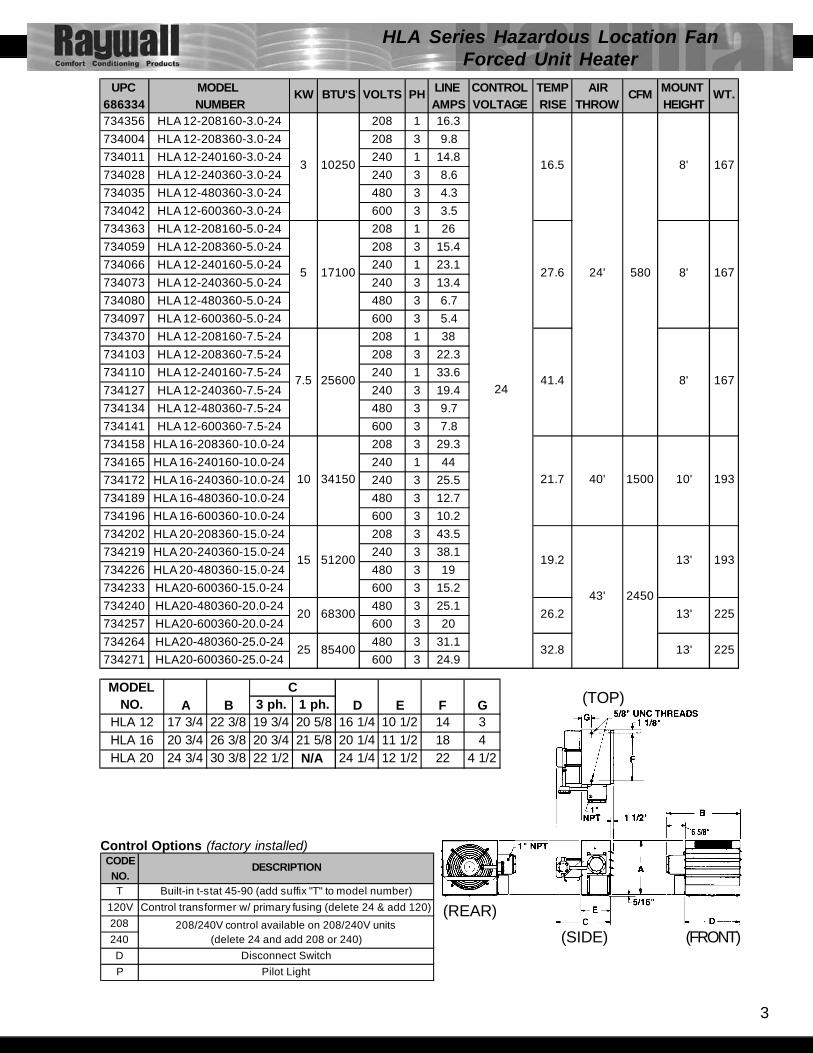
HLA Series Hazardous Location FanForced Unit Heater
Shown with optional pilot light and disconnect switch
Designed for rugged industrial applications in hazardous locations wherethe possibility of explosion or fire exists due to the presence of certainflammable gases, vapors, powdered metals or dust.
•Permanently sealed, liquid to air, finned tube heat exchanger core• Ethylene Glycol to water mixture uses a heat transfer fluid in the
heater core, providing freeze damage protection• High performance electric motor driven fan blows air across finned
tubes to effect uniform heat transfer and area heat distribution.• Manual Reset capillary type high limit provides high temp. Regulation
and is rated for 6,000 cycles of service•14 Ga. Steel cabinet epoxy coat finish contains heater core,motor,
and fan assembly
HLHMHanging Mounting KitSimpe and economical if adequeteoverhead structure exists. Requires1/2” pipe, cut and threaded (not sup-plied).
HLPMPipe Mounting KitParticularly useful in buildings withinsuffecient strength to use othertypes of mounts. Requires 3 1/2”pipe (4” O.D. - not supplied)
HLWMWall Mounting KitIdeal for use in buildings that havesubstantial walls. Arm only can alsobe bolted directly to structural steel.
UPC USE WITH686334 HEATERS734288 HLPM37 3.0 - 7.5 KW 37734295 HLPM10 10.0 KW 38734301 HLPM1525 15.0 - 25.0 KW 40734318 HLHM ALL 5734325 HLWM37 3.0 - 7.5 KW 27734332 HLWM10 10.0 KW 28734349 HLWM1525 15.0 - 25.0 KW 29
WT.NUMBER
FAN-FORCED SUSPENDED UNIT HEATERS 3-25 KW FOR CLASS I, GROUP C & D, DIVISION 1 & 2 AND CLASS II, GROUPS E, F & G, DIVISIONS 1 & 2.
THERMOSTAT MODELS: Hazardous Location ThermostatDimensions: 5 5/8” X 6 3/8” X 4 1/2”Finish: GrayRange: 50° - 90°Motor Rating: (full load) 1 1/2 HP @ 250VHeater LoadingRating: 22A @ 125-277VAC; 125VA @ 24VAC
Rated: Class I Group C & D, Class II Group E,F,G (Thermostat not rated for use in Group B environments)
- EPETD8S - single pole - EPETD8D - double pole
Optional built-inthermostat
Liquid-to-airexchanger
Hazardous locationrated motor
3
(FRONT)(SIDE)
(REAR)
(TOP)3 ph. 1 ph.HLA 12 17 3/4 22 3/8 19 3/4 20 5/8 16 1/4 10 1/2 14 3HLA 16 20 3/4 26 3/8 20 3/4 21 5/8 20 1/4 11 1/2 18 4HLA 20 24 3/4 30 3/8 22 1/2 N/A 24 1/4 12 1/2 22 4 1/2
D E F GC
A BMODEL
NO.
UPC MODEL LINE CONTROL TEMP AIR MOUNT 686334 NUMBER AMPS VOLTAGE RISE THROW HEIGHT734356 HLA 12-208160-3.0-24 208 1 16.3734004 HLA 12-208360-3.0-24 208 3 9.8734011 HLA 12-240160-3.0-24 240 1 14.8734028 HLA 12-240360-3.0-24 240 3 8.6734035 HLA 12-480360-3.0-24 480 3 4.3734042 HLA 12-600360-3.0-24 600 3 3.5734363 HLA 12-208160-5.0-24 208 1 26734059 HLA 12-208360-5.0-24 208 3 15.4734066 HLA 12-240160-5.0-24 240 1 23.1734073 HLA 12-240360-5.0-24 240 3 13.4734080 HLA 12-480360-5.0-24 480 3 6.7734097 HLA 12-600360-5.0-24 600 3 5.4734370 HLA 12-208160-7.5-24 208 1 38734103 HLA 12-208360-7.5-24 208 3 22.3734110 HLA 12-240160-7.5-24 240 1 33.6734127 HLA 12-240360-7.5-24 240 3 19.4734134 HLA 12-480360-7.5-24 480 3 9.7734141 HLA 12-600360-7.5-24 600 3 7.8734158 HLA 16-208360-10.0-24 208 3 29.3734165 HLA 16-240160-10.0-24 240 1 44734172 HLA 16-240360-10.0-24 240 3 25.5734189 HLA 16-480360-10.0-24 480 3 12.7734196 HLA 16-600360-10.0-24 600 3 10.2734202 HLA 20-208360-15.0-24 208 3 43.5734219 HLA 20-240360-15.0-24 240 3 38.1734226 HLA 20-480360-15.0-24 480 3 19734233 HLA20-600360-15.0-24 600 3 15.2734240 HLA20-480360-20.0-24 480 3 25.1734257 HLA20-600360-20.0-24 600 3 20734264 HLA20-480360-25.0-24 480 3 31.1734271 HLA20-600360-25.0-24 600 3 24.9
13'
13'
8'
10'
13'
167
167
167
193
193
225
225
8'
8'24'
40'
43'
580
1500
2450
24
16.5
27.6
41.4
21.7
19.2
26.2
32.8
34150
25600
17100
10250
15
20
25 85400
68300
51200
3
5
7.5
10
CFM WT.KW BTU'S VOLTS PH
CODENO.T Built-in t-stat 45-90 (add suffix "T" to model number)
120V Control transformer w/ primary fusing (delete 24 & add 120)208240D Disconnect SwitchP Pilot Light
DESCRIPTION
208/240V control available on 208/240V units (delete 24 and add 208 or 240)
Control Options (factory installed)
HLA Series Hazardous Location FanForced Unit Heater

4
SIZE UPC STAINLESS STEEL UPC WALL MTG. BRKT. UPC HANGING UPC PIPE MTG.KW 686334 COMBINATION BRACKET 686334 EPOXY COATED 686334 BRACKET * 686334 BRACKET *
3.3-15 713672 A5520/UHB 709002 W5520/WMK 713702 H5520/HMK 713689 P5520/PMK20-48 N/A N/A 713733 W5550/WMK 713719 H5550/HMK 713696 P5550/PMK
The Washdown Series unit heaters are electric unit heaters constructedfor use in area that require washing or hosing of equipment due to dirtyor dusty industrial environments in non hazardous locations. The totallyenclosed water-tight construction made with corrosion-resistant materialmake the heater ideal for industrial heating applications. The Washdownis made with all built-in controls and safety temperature controls wired ina non-metall ic Nema 4x control panel with single-point powerconnections.• Heavy-duty 304 16 Ga. Stainless steel shroud• Nema 4x non-metallic control panel• 24-volt transformer and control panel• 3-position switch (off-heat-fan)• Capillary thermostat with stainless steel sensor• Automatic reset thermal cutout• Totally enclosed U.L. listed motor• Pilot light (power on indicator)• Stainless steel finned tubular element• Control panel on bottom of unit for ease of installation and service• Disconnect switch with enclosure door interlock• Front grill rotates to direct airflow• Single point power connection• Epoxy painted cold roll steel models available – consult factory• Meets all U.L., NEC, and OSHA requirements(when installed as directed)• Corrosion-resistant in high humidity and water saturated area(for areas where corrosion-resistance is needed in non-hazardousarea, contact factory for heater application and optional materials)
Control Panel Back
3.0-7.5 12 18 19.75 15.25 16.25 6' 8.00 6.0010.0-15.0 14 19 21.75 15.25 18.00 6' 8.00 6.00
20-30 16 27 28.75 19.50 17.50 6' 15.50 4.5040-48 18 31 30.75 19.50 19.50 6' 21.75 2.75
HD E F GHEATER
SIZE A B C
UPC MODEL696334 No.503242 TW155 1 POLE503259 TW255 2 POLE
DESCRIPTION
NOTE: To delete the integral thermostat, drop the“T” in the model number
Remote Rain Tight Thermostat
*Material heavy duty epoxy coated.
WD Series Fan Forced Washdown Unit Heater

5
NOTE : ALL WASHDOWN UNITS ARE MADE TO ORDER-CONSULT FACTORY FOR LEAD TIMES
UPC CONTROL TEMP AIR MOUNT 686334 VOLTAGE RISE THROW HEIGHT713047 81WD3T01 208 1 15.9713054 83WD3T01 208 3 9.2713061 21WD3T01 240 1 13.7713078 23WD3T01 240 3 7.9713085 71WD3T01 277 1 11.9713092 43WD3T01 480 3 5713108 63WD3T01 600 3 3.2713115 81WD5T01 208 1 24.1
1 24.13 13.9
713139 21WD5T01 240 1 20.81 20.83 12.1
713153 71WD5T01 277 1 18.1713160 43WD5T01 480 3 6.1713177 63WD5T01 600 3 4.8713184 81WD7T01 208 1 36.1
1 36.13 20.8
713207 21WD7T01 240 1 31.31 31.33 13.1
713221 71WD7T01 277 1 27.1713238 43WD7T01 480 3 9.1713245 63WD7T01 600 3 7.2713252 81WD10T01 208 1 47.8
1 47.83 27.7
713276 21WD10T01 240 1 41.21 41.23 24.1
713290 71WD10T01 277 1 36.1713306 43WD10T01 480 3 12.1713313 63WD10T01 600 3 9.6713399 81WD15T01 208 1 72.1
1 72.13 41.7
713412 21WD15T01 240 1 62.51 62.53 36.1
713443 43WD15T01 480 3 18.1713450 63WD15T01 600 3 14.5713467 83WD20T01 208 3 55.6713474 23WD20T01 240 3 48.2713481 43WD20T01 480 3 24.1713498 63WD20T01 600 3 19.3713504 83WD25T01 208 3 69.5713511 23WD25T01 240 3 60.2713528 43WD25T01 480 3 30.1713535 63WD25T01 600 3 24.1713542 83WD30T01 208 3 83.4713559 23WD30T01 240 3 72.3713566 43WD30T01 480 3 36.1713573 63WD30T01 600 3 28.9713603 43WD40T01 480 3 48.2713610 63WD40T01 600 3 38.5713641 43WD48T01 480 3 57.8713658 63WD48T01 600 3 46.2
1800 6 19248 163824 84
40 136520 7042
1400 6 15825 85325 56
30 102390 68
20 68260 45
35
713405 82WD15T01 208
713429 22WD15T01 240
700 6 64
713269 82WD10T01 208
713283 22WD10T01 240
15
10 34130 45
28
51200 68
713191 82WD7T01 208
713214 22WD7T01 240
713122 82WD5T01 208
713146 22WD5T01 24020 400 6 58
3.3 11200
24
26
5 17100 40
7.5 25600 60
MODEL KW BTU'S VOLTS PH AMPS CFM WT.
WD Series Fan Forced Washdown Unit Heater

6
UPC MODEL CABINET NO. OF MAX FUSE686334 NUMBER LENGTH ELEMENTS SIZE655002 FEP-1812-1RA 120 15 20655019 FEP-1820-1RA 208 8.7 10655026 FEP-1824-1RA 240 7.5 10655033 FEP-1827-1RA 277 6.5 10655040 FEP-1848-1RA 480 3.8 5655057 FEP-3620-1RA 208 17.3 20655064 FEP-3624-1RA 240 15 20655071 FEP-3627-1RA 277 13 15655088 FEP-3648-1RA 480 7.5 10655170 FEP-3657-1RA 600 6 10655095 FEP-3820-1RA 208 18.3 20655101 FEP-3824-1RA 240 15.8 20655118 FEP-3827-1RA 277 13.7 15655125 FEP-3848-1RA 480 7.9 10655132 FEP-7620-1RA 208 36.5 40666149 FEP-7624-1RA 240 31.7 35655156 FEP-7627-1RA 277 27.4 30655163 FEP-7648-1RA 480 15.8 20655187 FEP-7657-1RA 600 12.7 15655194 FEP-0812-1RA 120 6.7 10655200 FEP-0820-1RA 208 3.8 5655217 FEP-0824-1RA 240 3.3 5655224 FEP-0827-1RA 277 2.9 5655231 FEP-0848-1RA 480 1.7 5655248 FEP-1612-1RA 120 13.3 15655255 FEP-1620-1RA 208 7.7 10655262 FEP-1624-1RA 240 6.7 10655279 FEP-1627-1RA 277 5.8 10655286 FEP-1648-1RA 480 3.3 5655385 FEP-1657-1RA 600 2.7 5655293 FEP-1712-1RA 120 14.2 20655309 FEP-1720-1RA 208 8.2 10655316 FEP-1724-1RA 240 7.1 10655323 FEP-1727-1RA 277 6.1 10655330 FEP-1748-1RA 480 3.5 5655347 FEP-3420-1RA 208 16.3 20355354 FEP-3424-1RA 240 14.2 20655361 FEP-3427-1RA 277 12.3 15655378 FEP-3448-1RA 480 7.1 10655392 FEP-3457-1RA 600 5.7 10
2730
5460
5802
11604
6143
12286
12969
25938
800
1600
1700
3400
1800
3600
3800
7600
34"
34"
58"
58"
34"
34"
58"
58"
1
2
1
2
1
2
1
2
CLA
SS
1, G
RO
UP
B, C
, & D
DIV
ISIO
N 1
& 2
(T-2
A)
53
6º F
UL
LIS
TED
& C
SA
CE
RTI
FIE
DC
LAS
S 1
, GR
OU
P B
, C, &
D D
IVIS
ION
1 &
2 (T
-2A
)
35
6º F
CS
A N
RTL
/C C
ER
TIFI
ED
50
54
80
85
50
54
80
85
AMPS W TLISTING WATTS VOLTSBTU'S
FEP Series Hazardous Location Convection Heater
UPC MODEL 686334 NUMBER538107 EPETD8S 50-90° F 24-277 VOLT SPST 5538077 EPETD8D 50-90° F 24-277 VOLT DPST 5
DESCRIPTION WT
SUFFIX DESCRIPTION EPETD8S single pole t-stat
factory mounted to 120v-277v unitsEPETD8D double pole t-stat factory
mounted to 120v- 277v unitsControl section with single pole t-stat
and disconnect switch (all units)Control section w/ single pole t-stat and disconnect switch & pilot light (all units)
C1-TDP
FACTORY INSTALLED OPTIONS
T1
T2
C1-TD
NEMA 4 HOSEDOWN RATED
Shown with optionaldisconnect, pilot light, & unit
mounted thermostat
• Cabinet size 18”high, 9” wide
• Color gray powdercoat textured finish
• Heavy Duty 16 Ga.steel
• Fully assembled• Slope top design
Wall Mounting Brackets(standard with Heater)
Junction box extends5-1/2 “ from the rightend of the housing

7
Belt Drive Portable BlowersCirculator Heads & Accessories
HP CFM RPM AMPS36" 1/2 14500 500 7.8/3.9 850896 PB-36-B-HL 135 850957 PBS-36-B-HL 16042" 3/4 18200 430 10.8/5.4 850902 PB-42-B-HL 150 850964 PBS-42-B-HL 17548" 1 22700 390 13.2/6.6 850919 PB-48-B-HL 173 850971 PBS-48-B-HL 198
120/240 V 1 PH
explosion
SIZE MOTOR TYPE
MOTOR STANDARD MODEL SWIVEL MODELUPC CODE
636334MODEL
NUMBERWT
(LBS)WT
(LBS)UPC CODE
636334MODEL
NUMBER
STANDARD
• Powder coated 20 gauge steel housing hasfront and rear roll formed embossments foradded strength and rigidity
• Swivel model rotates 360 in 12.5 incrementsand locks in place with a steel locking pin
• 10” hard rubber wheels• External junction boxes on dual voltage models
allow units to be wired for either voltage withoutremoving guards
• Hazardous Location Models have explosionproof motors and external junction boxes ratedfor Class I, Group D and Class II, Groups E, F& G, UL Listed
• Meets OSHA Standards• 1 year limited warranty
Hazardous Location Circulator Heads
Meets OSHA standards1 year limited warranty
Hazardous Location - Class I Group DClass II Group F & G1-speed unassembled head
Note: Can be used with any TPI Industrial circulator mount
120/240v 240/480vWt. 1 PHASE 3 PHASE
120v 240v/1 Ph 240v/3 Ph 480v (lbs.) MODEL No. MODEL No.24" 8000 5 2.6 1.4 0.7 66 ACH 24-EX1 ACH 24-EX330" 9200 5 2.6 1.4 0.7 69 ACH 30-EX1 ACH 30-EX3
SIZE AMPSCFM
Circulator Head Mounting Accessories
WALL MOUNT HDM-W 796101 3 ACM-W 796194 3I-BEAM MOUNT HDM-I 796118 9 ACM-I 796200 9
SUSPENSION MOUNT N/A N/A N/A ACM-S 796224 2CEILING MOUNT HDM-C 796125 3 ACM-C 796217 3
WHEEL KIT* HDWK 796392 2 HD-WK 796392 2
ACM-P 796187 34
GRAY COLORMODEL
NUMBERUPC CODE
686334WT (LBS)
PEDESTAL POLE & BASE
MOUNTS MODEL NUMBER
YELLOW (HEAVY DUTY)UPC CODE
686334WT
(LBS)
HDM-P 796095 34
SWIVEL
I-BEAM MOUNT WALL MOUNT
CEILINGMOUNT
SUSPENSIONMOUNT PEDESTAL
MOUNT
WHEEL KIT
*Base is not included with the wheel kit.

8
• Explosion proof motors are Class I, Div I Group D and Class II, Div I, Groups F & G• 360° swivel on high and medium stand units• 14 gauge steel body and stand• Acid resistant coating available• Baked enamal coating• Cast aluminum props• Meets OSHA requirements• 1 year limited warranty
MODEL FAN WHEEL SHIPNO. SIZE SIZE WT.
CAS-18 18"-30" 4" 10CAS-48 36"-48" 6" 14
Heavy Duty Direct Drive Blowers
H.P. 1 PH 3 PH RATING
SW-1/4 SW-1/4-3 1/4-1/3SW-1/2 SW-1/2-3 1/2-3/4SW-1 SW-1-3 1
SW-1.5 SW-1.5-3 1 1/2N/A SW-2-3 2N/A SW-3-3 3N/A SW-5-3 5N/A SW-7.5-3 7 1/2
MODEL NUMBERManual Starter Switches
Polyolifin Casters (for low & medium stand)
Note: Single phase motors are field convertable 115v/230v.Three phase are field convertable 230v/460v. Motors set atfactory to lower voltage unless requested on purchase order.
MODEL DB'SNUMBER AT 10 LOW MED HIGH 1 PH 3 PH 1 PH 3 PH 1 PH 3 PH
- L - L - 3 - M - M - 3 - H - H - 3MCD18-1/4 1/4 3050 74 103 145 210 - L - L - 3 - M - M - 3 - H - H - 3MCD18-1/3 1/3 3450 76 105 150 215 - L - L - 3 - M - M - 3 - H - H - 3MCD18-1 1 4600 77 117 165 230 - L - L - 3 - M - M - 3 - H - H - 3
MCD24-1/4 1/4 1725 5200 80 115 165 230 - L - L - 3 - M - M - 3 - H - H - 3MCD24-1/3 1/3 1140 5300 74 126 175 250 - L - L - 3 - M - M - 3 - H - H - 3MCD24-1/2 1/2 1725 6000 80 120 170 240 - L - L - 3 - M - M - 3 - H - H - 3MCD24-3/4 3/4 1140 6900 74 140 190 260 N/A - L - 3 N/A - M - 3 N/A - H - 3MCD24-1 1 1725 7400 82 130 180 250 - L - L - 3 - M - M - 3 - H - H - 3
MCD24-1.5 1 1/2 1725 8200 84 137 190 255 - L - L - 3 - M - M - 3 - H - H - 3MCD24-3 3 1725 10500 87 160 210 270 N/A - L - 3 N/A - M - 3 N/A - H - 3
MCD30-1/3 1/3 1140 6900 80 150 205 260 - L - L - 3 - M - M - 3 - H - H - 3MCD30-1/2 1/2 1725 8900 86 141 195 250 - L - L - 3 - M - M - 3 - H - H - 3MCD30-3/4 3/4 1140 10400 80 210 260 320 N/A - L - 3 N/A - M - 3 N/A - H - 3MCD30-1 1 1140 11200 71 200 260 310 - L - L - 3 - M - M - 3 - H - H - 3
MCD30-1.5 1 1/2 1725 12000 92 200 250 310 - L - L - 3 - M - M - 3 - H - H - 3MCD30-2 2 1140 14000 84 225 270 330 N/A - L - 3 N/A - M - 3 N/A - H - 3MCD30-3 3 1725 16000 94 220 265 325 N/A - L - 3 N/A - M - 3 N/A - H - 3MCD36-1 1 1140 13000 82 250 320 375 - L - L - 3 - M - M - 3 - H - H - 3
MCD36-1.5 1 1/2 1725 14850 88 250 320 375 - L - L - 3 - M - M - 3 - H - H - 3MCD36-2 2 1140 17500 82 255 325 380 N/A - L - 3 N/A - M - 3 N/A - H - 3MCD36-3 3 1725 18500 90 260 330 390 N/A - L - 3 N/A - M - 3 N/A - H - 3MCD36-5 5 1725 23000 94 260 330 390 N/A - L - 3 N/A - M - 3 N/A - H - 3MCD42-2 2 1140 19500 85 315 415 565 N/A - L - 3 N/A - M - 3 N/A - H - 3MCD42-5 5 1725 27000 98 320 420 570 N/A - L - 3 N/A - M - 3 N/A - H - 3MCD48-5 5 1140 32000 92 500 620 710 N/A - L - 3 N/A - M - 3 N/A - H - 3
MCD48-7.5 7 1/2 1140 37000 105 625 745 835 N/A - L - 3 N/A - M - 3 N/A - H - 3MCD48-10 10 1140 41000 105 682 800 890 N/A - L - 3 N/A - M - 3 N/A - H - 3
42"
48"
172518"
24"
30"
36"
MODEL NUMBER SUFFIX'S
HP RPM CFMSIZESTAND OPTIONS AVAILABILITYSHIPPING WT.
STAND
Low Stand Medium Stand High Stand

9
Permanent Mount Blowers
• Explosion proof motors are Class I, Div I Group D and Class II, Div I, Groups F & G• 14 gauge steel body and stand• Front and rear spiral guards• Meets OSHA requirements• 1 year limited warranty
2-Way Swivel1-Way Swivel
MODEL DB'S 1-WAY 2-WAYNUMBER AT 10' SWIVEL SWIVEL 1 PH 3 PH 1 PH 3 PH
- T -T - 3 - S -S - 3MCD18-1/4 1/4 1725 3050 74 130 140 - T -T - 3 - S -S - 3MCD18-1/3 1/3 1725 3450 76 135 145 - T -T - 3 - S -S - 3MCD18-1 1 1725 4600 77 145 155 - T -T - 3 - S -S - 3
MCD24-1/4 1/4 1725 5200 80 145 155 - T -T - 3 - S -S - 3MCD24-1/3 1/3 1140 5300 74 155 165 - T -T - 3 - S -S - 3MCD24-1/2 1/2 1725 6000 80 150 160 - T -T - 3 - S -S - 3MCD24-3/4 3/4 1140 6900 74 170 180 N/A -T - 3 N/A -S - 3MCD24-1 1 1725 7400 82 160 170 - T -T - 3 - S -S - 3
MCD24-1 1/2 1 1/2 1725 8200 84 165 175 - T -T - 3 - S -S - 3MCD24-3 3 1725 10500 87 190 200 N/A -T - 3 N/A -S - 3
MCD30-1/3 1/3 1140 6900 80 180 190 - T -T - 3 - S -S - 3MCD30-1/2 1/2 1725 8900 86 170 180 - T -T - 3 - S -S - 3MCD30-3/4 3/4 1140 10400 80 240 250 N/A -T - 3 N/A -S - 3MCD30-1 1 1140 11200 81 230 240 - T -T - 3 - S -S - 3
MCD30-1 1/2 1 1/2 1725 12000 92 230 240 - T -T - 3 - S -S - 3MCD30-2 2 1140 14000 84 255 265 N/A -T - 3 N/A -S - 3MCD30-3 3 1725 16000 94 250 260 N/A -T - 3 N/A -S - 3MCD36-1 1 1140 13000 82 295 305 - T -T - 3 - S -S - 3
MCD36-1 1/2 1 1/2 1725 14850 88 295 305 - T -T - 3 - S -S - 3MCD36-2 2 1140 17500 82 300 310 N/A -T - 3 N/A -S - 3MCD36-3 3 1725 18500 90 315 325 N/A -T - 3 N/A -S - 3MCD36-5 5 1725 23000 94 305 315 N/A -T - 3 N/A -S - 3
18"
24"
30"
36"
BLADE DIA.
1-WAY SWIVEL 2-WAY SWIVELEXPLOSION PROOFSHIPPING WT.
MODEL NUMBER SUFFIX'S
HP RPM CFM
Note: Single phase motors are field convertable 115v/230v.Three phase are field convertable 230v/460v. Motors set atfactory to lower voltage unless requested on purchase order.
10
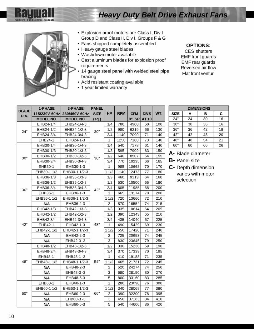
SIZE A B C24" 24 30 1630" 30 36 1636" 36 42 1842" 42 48 2048" 48 54 2160" 60 66 26
DIMENSIONS1-PHASE 3-PHASE PANEL 115/230V-60Hz 230/460V-60Hz SIZE CFM DB'S
MODEL NO. MODEL NO. (sq.) 0" SP AT 10EHB24-1/4 EHB24-1/4-3 1/4 780 4900 60 100EHB24-1/2 EHB24-1/2-3 1/2 980 6219 66 130EHB24-3/4 EHB24-3/4-3 3/4 1140 7090 71 140EHB24-1 EHB24-1-3 1 1250 7180 73 140
EHB30-1/4 EHB30-1/4-3 1/4 540 7178 61 140EHB30-1/3 EHB30-1/3-3 1/3 595 7909 63 150EHB30-1/2 EHB30-1/2-3 1/2 640 8507 64 155EHB30-3/4 EHB30-3/4-3 3/4 770 10235 66 165EHB30-1 EHB30-1-3 1 985 10668 70 170
EHB30-1 1/2 EHB30-1 1/2-3 1 1/2 1140 12473 77 180EHB36-1/3 EHB36-1/3-3 1/3 460 9113 64 160EHB36-1/2 EHB36-1/2-3 1/2 530 10500 66 180EHB36-3/4 EHB36-3/4-3 3/4 605 11985 68 200EHB36-1 EHB36-1-3 1 665 13174 70 200
EHB36-1 1/2 EHB36-1 1/2-3 1 1/2 720 13660 72 210N/A EHB36-2-3 2 870 16554 74 215
EHB42-1/3 EHB42-1/3-3 1/3 335 10614 64 205EHB42-1/2 EHB42-1/2-3 1/2 390 12343 65 210EHB42-3/4 EHB42-3/4-3 3/4 435 14040 67 225EHB42-1 EHB42-1-3 1 490 15429 69 230
EHB42-1 1/2 EHB42-1 1/2-3 1 1/2 550 17420 71 240N/A EHB42-2-3 2 725 20653 74 245N/A EHB42-3 -3 3 830 23645 79 250
EHB48-1/2 EHB48-1/2-3 1/2 330 15230 69 190EHB48-3/4 EHB48-3/4-3 3/4 370 17339 70 195EHB48-1 EHB48-1 -3 1 410 19188 71 235
EHB48-1 1/2 EHB48-1 1/2-3 1 1/2 465 21731 72 245N/A EHB48-2-3 2 520 24274 74 250N/A EHB48-3 -3 3 680 28150 80 270N/A EHB48-5-3 5 800 33160 83 285
EHB60-1 EHB60-1-3 1 280 23090 76 380EHB60-1 1/2 EHB60-1 1/2-3 1 1/2 340 28068 77 390
N/A EHB60-2-3 2 390 32200 78 395N/A EHB60-3 -3 3 450 37183 84 410N/A EHB60-5-3 5 540 44600 86 420
48"
60"
30"
36"
42"
48"
54"
66"
24"
30"
36"
42"
WT.HP RPMBLADE
DIA.
Heavy Duty Belt Drive Exhaust Fans
• Explosion proof motors are Class I, Div IGroup D and Class II, Div I, Groups F & G
• Fans shipped completely assembled• Heavy gauge steel blades• Washdown motor available• Cast aluminum blades for explosion proof
requirements• 14 gauge steel panel with welded steel pipe
bracing• Acid resistant coating available• 1 year limited warranty
A- Blade diameterB- Panel sizeC- Depth dimension
varies with motor selection
OPTIONS:CES shutters
EMF front guardsEMF rear guardsReversed air flowFlat front venturi

11
1-PHASE 3-PHASE PANEL 115/230V-60Hz 230/460V-60Hz SIZE CFM DB'S
MODEL NO. MODEL NO. (sq.) 0" SP AT 1012" EHD12-1/4 EHD12-1/4-3 16" 1/4 1725 1180 74 3516" EHD16-1/4 EHD16-1/4-3 20" 1/4 1725 2800 75 45
EHD18-1/3 EHD18-1/3-3 1/3 1725 3375 75 60EHD18-1/2 EHD18-1/2-3 1/2 1725 4150 76 60EHD20-1/4 EHD20-1/4-3 1/4 1725 3720 75 60EHD20-1/2 EHD20-1/2-3 1/2 1725 4800 76 65EHD20-1 EHD20-1-3 1 1725 6900 77 70
EHD24-1/4 EHD24-1/4-3 1/4 1725 5200 82 135EHD24-1/3 EHD24-1/3-3 1/3 1150 4975 75 145EHD24-1/2 EHD24-1/2-3 1/2 1725 6510 82 140EHD24-3/4 EHD24-3/4-3 3/4 1725 6900 83 145EHD24-1 EHD24-1-3 1 1725 7425 83 155EHD24-2 EHD24-2-3 2 1725 9525 83 165EHD24-3 EHD24-3 3 1725 10500 85 170EHD30-1/3 EHD30-1/3-3 1/3 1150 6950 79 145EHD30-1/2 EHD30-1/2-3 1/2 1725 8980 89 135EHD30-3/4 EHD30-3/4-3 3/4 1150 10440 79 175EHD30-1 EHD30-1-3 1 870 10640 74 215
EHD30-1 1/2 EHD30-1 1/2-3 1 1/2 1725 12000 89 165EHD30-2 EHD30-2-3 2 1150 14000 82 215EHD30-3 EHD30-3 -3 3 1725 16000 89 190EHD36-1 EHD36-1-3 1 1150 13600 84 225EHD36-2 EHD36-2-3 2 1150 17620 84 250EHD36-3 EHD36-3-3 3 1150 20500 85 255EHD36-5 EHD36-5-3 5 1725 28000 94 250EHD42-1 EHD42-1-3 1 870 15800 82 300EHD42-2 EHD42-2-3 2 1150 17964 88 260EHD42-3 EHD42-3-3 3 1150 24500 88 270EHD42-5 EHD42-5-3 5 1150 28970 88 285EHD48-3 EHD48-3-3 3 1150 28600 92 290EHD48-5 EHD48-5-3 5 1150 32000 94 305EHD60-3 EHD60-3-3 3 1150 40000 97 700EHD60-5 EHD60-5-3 5 1150 45000 97 730
EHD60-7 1/2 EHD60-7 1/2-3 7 1/2 870 47000 92 740EHD60-10 EHD60-10-3 10 870 57200 93 450
HP RPM WT.
18" 24"
BLADE DIA.
20"
24"
30"
36"
24"
30"
36"
66"
42"
48"
60"
42"
48"
54"
SIZE A B C12" 12 16 1116" 16 20 1120" 20 24 1324" 24 30 1530" 30 36 1536" 36 42 1842" 42 48 1848" 48 54 2060" 60 66 22
DIMENSIONS
Heavy Duty Direct Drive Exhaust Fans
• Explosion proof motors are Class I, Div IGroup D and Class II, Div I, Groups F & G
• Fans shipped completely assembled• Heavy gauge steel blades• Washdown motor available• Cast aluminum blades for explosion proof requirements• 14 gauge steel panel with welded steel pipe bracing• Acid resistant coating available• 1 year limited warranty
A- Blade diameterB- Panel sizeC- Depth dimension
varies with motor selection
OPTIONS:CES shutters
EMF front guardsEMF rear guardsReversed air flowFlat front venturi
12
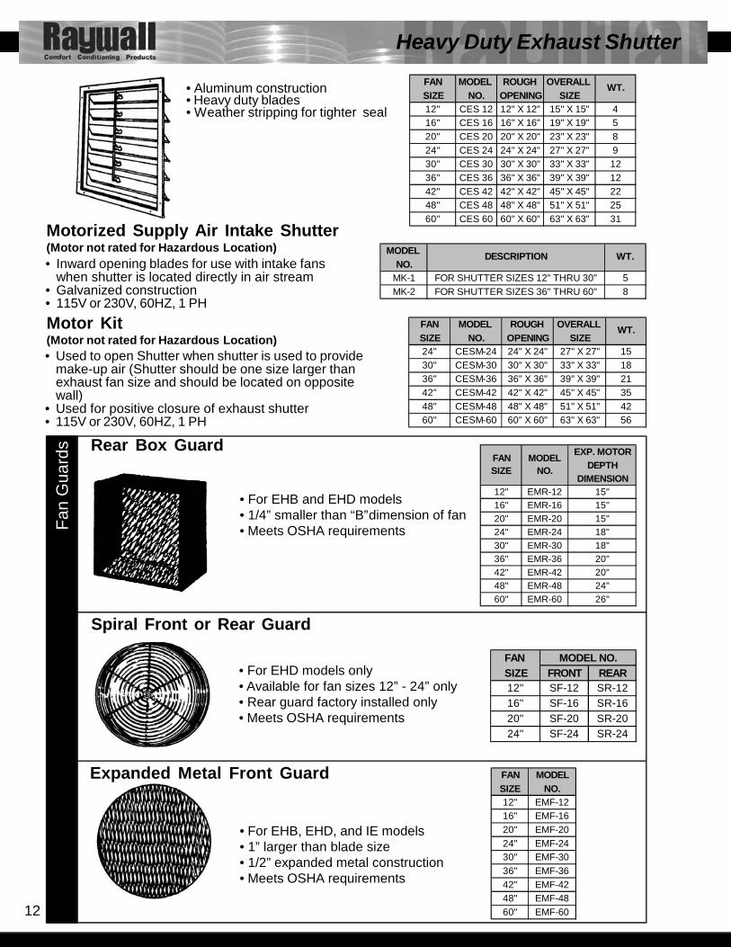
Heavy Duty Exhaust Shutter
MODEL NO.
MK-1 FOR SHUTTER SIZES 12" THRU 30" 5MK-2 FOR SHUTTER SIZES 36" THRU 60" 8
DESCRIPTION WT.
FAN SIZE FRONT REAR12" SF-12 SR-1216" SF-16 SR-1620" SF-20 SR-2024" SF-24 SR-24
MODEL NO.
FAN MODELSIZE NO.12" EMF-1216" EMF-1620" EMF-2024" EMF-2430" EMF-3036" EMF-3642" EMF-4248" EMF-4860" EMF-60
FAN MODEL ROUGH OVERALL SIZE NO. OPENING SIZE12" CES 12 12" X 12" 15" X 15" 416" CES 16 16" X 16" 19" X 19" 520" CES 20 20" X 20" 23" X 23" 824" CES 24 24" X 24" 27" X 27" 930" CES 30 30" X 30" 33" X 33" 1236" CES 36 36" X 36" 39" X 39" 1242" CES 42 42" X 42" 45" X 45" 2248" CES 48 48" X 48" 51" X 51" 2560" CES 60 60" X 60" 63" X 63" 31
WT.
EXP. MOTORDEPTH
DIMENSION12" EMR-12 15"16" EMR-16 15"20" EMR-20 15"24" EMR-24 18"30" EMR-30 18"36" EMR-36 20"42" EMR-42 20"48" EMR-48 24"60" EMR-60 26"
FANSIZE
MODELNO.
FAN MODEL ROUGH OVERALL SIZE NO. OPENING SIZE24" CESM-24 24" X 24" 27" X 27" 1530" CESM-30 30" X 30" 33" X 33" 1836" CESM-36 36" X 36" 39" X 39" 2142" CESM-42 42" X 42" 45" X 45" 3548" CESM-48 48" X 48" 51" X 51" 4260" CESM-60 60" X 60" 63" X 63" 56
WT.
• Used to open Shutter when shutter is used to providemake-up air (Shutter should be one size larger thanexhaust fan size and should be located on oppositewall)
• Used for positive closure of exhaust shutter• 115V or 230V, 60HZ, 1 PH
Motor Kit(Motor not rated for Hazardous Location)
Motorized Supply Air Intake Shutter(Motor not rated for Hazardous Location)• Inward opening blades for use with intake fans
when shutter is located directly in air stream• Galvanized construction• 115V or 230V, 60HZ, 1 PH
Rear Box Guard
Spiral Front or Rear Guard
Expanded Metal Front Guard
• For EHB and EHD models• 1/4” smaller than “B”dimension of fan• Meets OSHA requirements
• For EHD models only• Available for fan sizes 12” - 24” only• Rear guard factory installed only• Meets OSHA requirements
• For EHB, EHD, and IE models• 1” larger than blade size• 1/2” expanded metal construction• Meets OSHA requirements
Fan
Gua
rds
• Aluminum construction
• Weather stripping for tighter seal• Heavy duty blades
13
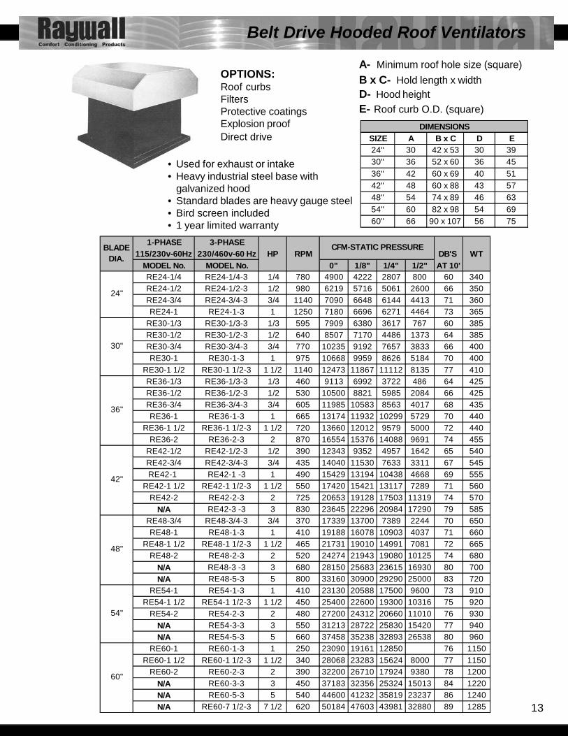
1-PHASE 3-PHASE115/230v-60Hz 230/460v-60 Hz HP RPM DB'S WT
MODEL No. MODEL No. 0" 1/8" 1/4" 1/2" AT 10'RE24-1/4 RE24-1/4-3 1/4 780 4900 4222 2807 800 60 340RE24-1/2 RE24-1/2-3 1/2 980 6219 5716 5061 2600 66 350RE24-3/4 RE24-3/4-3 3/4 1140 7090 6648 6144 4413 71 360RE24-1 RE24-1-3 1 1250 7180 6696 6271 4464 73 365
RE30-1/3 RE30-1/3-3 1/3 595 7909 6380 3617 767 60 385RE30-1/2 RE30-1/2-3 1/2 640 8507 7170 4486 1373 64 385RE30-3/4 RE30-3/4-3 3/4 770 10235 9192 7657 3833 66 400RE30-1 RE30-1-3 1 975 10668 9959 8626 5184 70 400
RE30-1 1/2 RE30-1 1/2-3 1 1/2 1140 12473 11867 11112 8135 77 410RE36-1/3 RE36-1/3-3 1/3 460 9113 6992 3722 486 64 425RE36-1/2 RE36-1/2-3 1/2 530 10500 8821 5985 2084 66 425RE36-3/4 RE36-3/4-3 3/4 605 11985 10583 8563 4017 68 435RE36-1 RE36-1-3 1 665 13174 11932 10299 5729 70 440
RE36-1 1/2 RE36-1 1/2-3 1 1/2 720 13660 12012 9579 5000 72 440RE36-2 RE36-2-3 2 870 16554 15376 14088 9691 74 455
RE42-1/2 RE42-1/2-3 1/2 390 12343 9352 4957 1642 65 540RE42-3/4 RE42-3/4-3 3/4 435 14040 11530 7633 3311 67 545RE42-1 RE42-1 -3 1 490 15429 13194 10438 4668 69 555
RE42-1 1/2 RE42-1 1/2-3 1 1/2 550 17420 15421 13117 7289 71 560RE42-2 RE42-2-3 2 725 20653 19128 17503 11319 74 570
N/A RE42-3 -3 3 830 23645 22296 20984 17290 79 585RE48-3/4 RE48-3/4-3 3/4 370 17339 13700 7389 2244 70 650RE48-1 RE48-1-3 1 410 19188 16078 10903 4037 71 660
RE48-1 1/2 RE48-1 1/2-3 1 1/2 465 21731 19010 14991 7081 72 665RE48-2 RE48-2-3 2 520 24274 21943 19080 10125 74 680
N/A RE48-3 -3 3 680 28150 25683 23615 16930 80 700N/A RE48-5-3 5 800 33160 30900 29290 25000 83 720
RE54-1 RE54-1-3 1 410 23130 20588 17500 9600 73 910RE54-1 1/2 RE54-1 1/2-3 1 1/2 450 25400 22600 19300 10316 75 920
RE54-2 RE54-2-3 2 480 27200 24312 20660 11010 76 930N/A RE54-3-3 3 550 31213 28722 25830 15420 77 940N/A RE54-5-3 5 660 37458 35238 32893 26538 80 960
RE60-1 RE60-1-3 1 250 23090 19161 12850 76 1150RE60-1 1/2 RE60-1 1/2-3 1 1/2 340 28068 23283 15624 8000 77 1150
RE60-2 RE60-2-3 2 390 32200 26710 17924 9380 78 1200N/A RE60-3-3 3 450 37183 32356 25324 15013 84 1220N/A RE60-5-3 5 540 44600 41232 35819 23237 86 1240N/A RE60-7 1/2-3 7 1/2 620 50184 47603 43981 32880 89 1285
54"
60"
30"
36"
42"
48"
CFM-STATIC PRESSURE
24"
BLADE DIA.
Belt Drive Hooded Roof Ventilators
SIZE A B x C D E24" 30 42 x 53 30 3930" 36 52 x 60 36 4536" 42 60 x 69 40 5142" 48 60 x 88 43 5748" 54 74 x 89 46 6354" 60 82 x 98 54 6960" 66 90 x 107 56 75
DIMENSIONS
OPTIONS:Roof curbsFiltersProtective coatingsExplosion proofDirect drive
• Used for exhaust or intake• Heavy industrial steel base with
galvanized hood• Standard blades are heavy gauge steel• Bird screen included• 1 year limited warranty
A- Minimum roof hole size (square)B x C- Hold length x widthD- Hood heightE- Roof curb O.D. (square)

14
1-PHASE 3-PHASE115/230V-60Hz 230-460V-60Hz HP RPM DB'S WT.
MODEL No. MODEL No. 0" 1/8" 1/4" 1/2" AT 10UEB24-1/3 UEB24-1/3-3 1/3 780 4900 4222 2807 800 64 300UEB24-1/2 UEB24-1/2-3 1/2 980 6219 5716 5661 2600 66 305UEB24-3/4 UEB24-3/4-3 3/4 1140 7090 6648 6144 4413 71 310UEB30-1/2 UEB30-1/2-3 1/2 640 8507 7170 4486 1373 64 350UEB30-3/4 UEB30-3/4-3 3/4 770 10235 9192 7657 3833 66 360UEB30-1 UEB30-1 -3 1 975 10668 9959 8626 5184 70 370
UEB36-1/2 UEB36-1/2-3 1/2 530 10500 8821 5985 2084 66 360UEB36-3/4 UEB36-3/4-3 3/4 605 11985 10583 8563 4017 68 370UEB36-1 UEB36-1 -3 1 665 13174 11932 10299 5729 70 390
UEB361 1/2 UEB361 1/2-3 1 1/2 720 13660 12012 9579 5000 72 395UEB42-3/4 UEB42-3/4-3 3/4 435 14040 11530 7633 3311 67 455UEB42-1 UEB42-1-3 1 490 15429 13194 10438 4668 69 465
UEB42-1 1/2 UEB42-1 1/2-3 1 1/2 550 17420 15421 13117 7289 71 470N/A UEB42-2-3 2 725 20653 19128 17503 11319 74 485N/A UEB42-3/4-3 3 830 23645 22296 20984 17290 79 495
UEB48-3/4 UEB48-3/4-3 3/4 370 17339 13700 7389 2244 70 505UEB48-1 UEB48-1-3 1 410 19188 16078 10903 4037 71 520
UEB48-1 1/2 UEB48-1 1/2-3 1 1/2 465 21731 19010 14991 7081 72 535N/A UEB48-2-3 2 520 24274 21943 19080 10125 74 545N/A UEB48-3/4-3 3 680 28150 25683 23615 16930 80 560
UEB54-1 UEB54-1-3 1 410 23130 20588 17500 9600 73 870UEB54-1 1/2 UEB54-1 1/2-3 1 1/2 450 25400 22600 19300 10316 75 880
N/A UEB54-2-3 2 480 27200 24312 20660 11010 76 890N/A UEB54-3-3 3 550 31213 28722 25830 15420 80 900N/A UEB54-5-3 5 660 37458 35238 32843 26538 82 920
UEB60-1 1/2 UEB60-1 1/2-3 1 1/2 340 28068 23203 15624 8000 78 940N/A UEB60-2-3 2 390 32200 26710 17924 9380 80 960N/A UEB60-3-3 3 450 37183 32356 25324 15013 84 985N/A UEB60-5-3 5 540 44600 41232 35819 23237 86 1000
54"
60"
30"
36"
42"
48"
CFM - STATIC PRESSURE
24"
BLADE DIA.
SIZE A B C D24" 34 30 39 1930" 40 36 45 2236" 46 42 51 2542" 52 48 57 2748" 58 54 63 3054" 64 60 69 3660" 70 66 75 42
DIMENSIONS
Belt Drive Roof Ventilators
A- Minimum roof hole size (square)B- Wind band O.D.C- Roof curb O.D. (square)D- Wind band height
OPTIONS:Prefabricated CurbsProtective coatingsDisconnect switch
• Explosion proof motors are Class I, Division I, Group D and Class II Division II, Groups F & G• Wind band is 18 gauge galvanized steel• Standard blades are heavy gauge steel• Galvanized steel butterfly damper with rubber stop and seals• Size of roof opening to be 6” larger than fan size (B dimensions)• 1 year limited warranty
15
1-PHASE 3-PHASE115/230V-60Hz 230-460V-60Hz HP RPM DB'S WT.
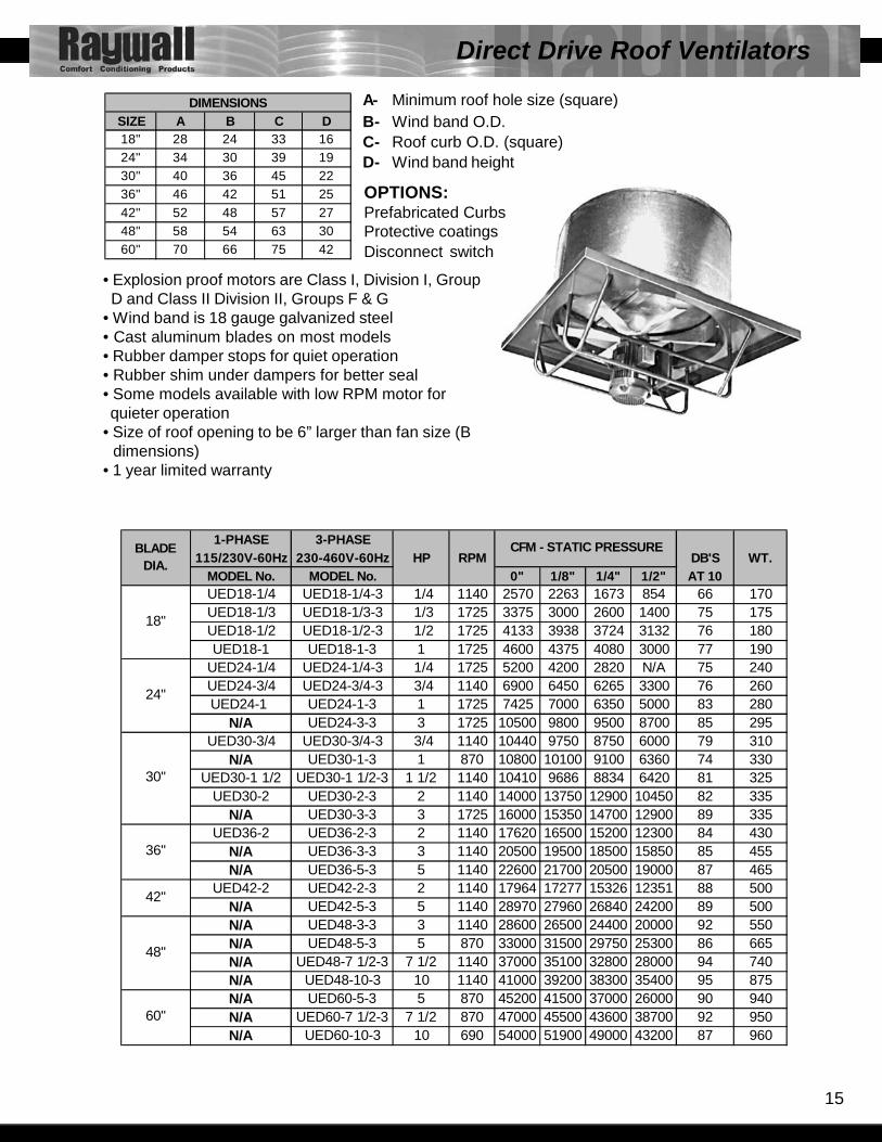
MODEL No. MODEL No. 0" 1/8" 1/4" 1/2" AT 10UED18-1/4 UED18-1/4-3 1/4 1140 2570 2263 1673 854 66 170UED18-1/3 UED18-1/3-3 1/3 1725 3375 3000 2600 1400 75 175UED18-1/2 UED18-1/2-3 1/2 1725 4133 3938 3724 3132 76 180UED18-1 UED18-1-3 1 1725 4600 4375 4080 3000 77 190
UED24-1/4 UED24-1/4-3 1/4 1725 5200 4200 2820 N/A 75 240UED24-3/4 UED24-3/4-3 3/4 1140 6900 6450 6265 3300 76 260UED24-1 UED24-1-3 1 1725 7425 7000 6350 5000 83 280
N/A UED24-3-3 3 1725 10500 9800 9500 8700 85 295UED30-3/4 UED30-3/4-3 3/4 1140 10440 9750 8750 6000 79 310
N/A UED30-1-3 1 870 10800 10100 9100 6360 74 330UED30-1 1/2 UED30-1 1/2-3 1 1/2 1140 10410 9686 8834 6420 81 325
UED30-2 UED30-2-3 2 1140 14000 13750 12900 10450 82 335N/A UED30-3-3 3 1725 16000 15350 14700 12900 89 335
UED36-2 UED36-2-3 2 1140 17620 16500 15200 12300 84 430N/A UED36-3-3 3 1140 20500 19500 18500 15850 85 455N/A UED36-5-3 5 1140 22600 21700 20500 19000 87 465
UED42-2 UED42-2-3 2 1140 17964 17277 15326 12351 88 500N/A UED42-5-3 5 1140 28970 27960 26840 24200 89 500N/A UED48-3-3 3 1140 28600 26500 24400 20000 92 550N/A UED48-5-3 5 870 33000 31500 29750 25300 86 665N/A UED48-7 1/2-3 7 1/2 1140 37000 35100 32800 28000 94 740N/A UED48-10-3 10 1140 41000 39200 38300 35400 95 875N/A UED60-5-3 5 870 45200 41500 37000 26000 90 940N/A UED60-7 1/2-3 7 1/2 870 47000 45500 43600 38700 92 950N/A UED60-10-3 10 690 54000 51900 49000 43200 87 960
BLADE DIA.
CFM - STATIC PRESSURE
18"
24"
30"
36"
42"
48"
60"
SIZE A B C D18" 28 24 33 1624" 34 30 39 1930" 40 36 45 2236" 46 42 51 2542" 52 48 57 2748" 58 54 63 3060" 70 66 75 42
DIMENSIONS
Direct Drive Roof Ventilators
• Explosion proof motors are Class I, Division I, Group D and Class II Division II, Groups F & G• Wind band is 18 gauge galvanized steel• Cast aluminum blades on most models• Rubber damper stops for quiet operation• Rubber shim under dampers for better seal• Some models available with low RPM motor for quieter operation• Size of roof opening to be 6” larger than fan size (B dimensions)• 1 year limited warranty
A- Minimum roof hole size (square)B- Wind band O.D.C- Roof curb O.D. (square)D- Wind band height
OPTIONS:Prefabricated CurbsProtective coatingsDisconnect switch
16
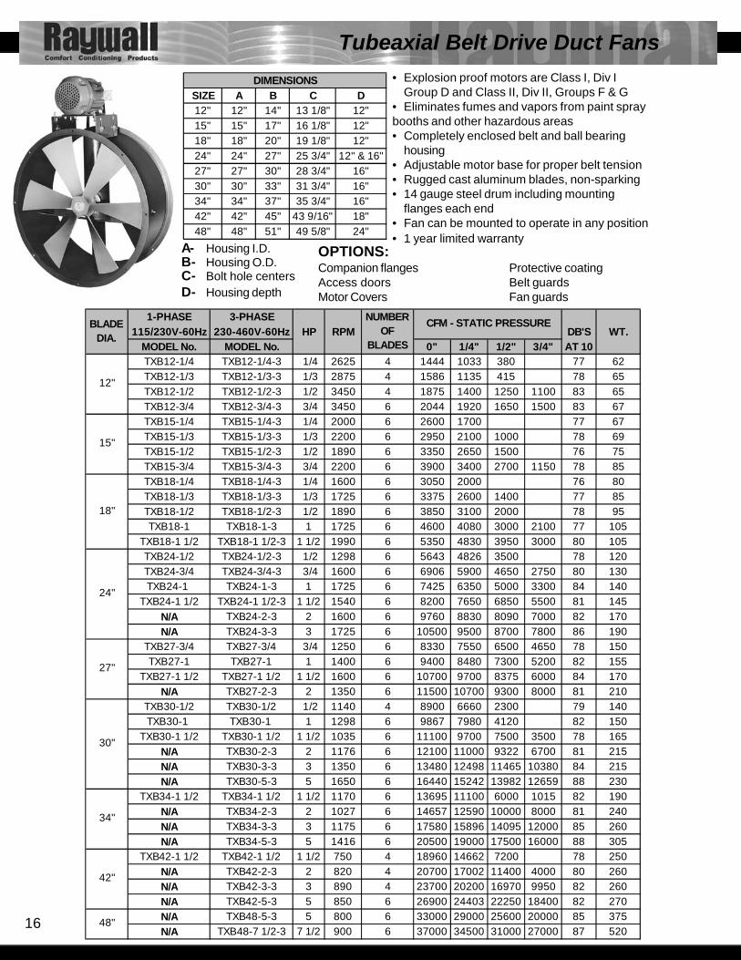
Tubeaxial Belt Drive Duct Fans• Explosion proof motors are Class I, Div I
Group D and Class II, Div II, Groups F & G• Eliminates fumes and vapors from paint spraybooths and other hazardous areas• Completely enclosed belt and ball bearing
housing• Adjustable motor base for proper belt tension• Rugged cast aluminum blades, non-sparking• 14 gauge steel drum including mounting
flanges each end• Fan can be mounted to operate in any position• 1 year limited warranty
SIZE A B C D12" 12" 14" 13 1/8" 12"15" 15" 17" 16 1/8" 12"18" 18" 20" 19 1/8" 12"24" 24" 27" 25 3/4" 12" & 16"27" 27" 30" 28 3/4" 16"30" 30" 33" 31 3/4" 16"34" 34" 37" 35 3/4" 16"42" 42" 45" 43 9/16" 18"48" 48" 51" 49 5/8" 24"
DIMENSIONS
A- Housing I.D.B- Housing O.D.C- Bolt hole centersD- Housing depth
OPTIONS:Companion flanges Protective coatingAccess doors Belt guardsMotor Covers Fan guards
1-PHASE 3-PHASE115/230V-60Hz 230-460V-60Hz HP RPM DB'S WT.
MODEL No. MODEL No. 0" 1/4" 1/2" 3/4" AT 10TXB12-1/4 TXB12-1/4-3 1/4 2625 4 1444 1033 380 77 62TXB12-1/3 TXB12-1/3-3 1/3 2875 4 1586 1135 415 78 65TXB12-1/2 TXB12-1/2-3 1/2 3450 4 1875 1400 1250 1100 83 65TXB12-3/4 TXB12-3/4-3 3/4 3450 6 2044 1920 1650 1500 83 67TXB15-1/4 TXB15-1/4-3 1/4 2000 6 2600 1700 77 67TXB15-1/3 TXB15-1/3-3 1/3 2200 6 2950 2100 1000 78 69TXB15-1/2 TXB15-1/2-3 1/2 1890 6 3350 2650 1500 76 75TXB15-3/4 TXB15-3/4-3 3/4 2200 6 3900 3400 2700 1150 78 85TXB18-1/4 TXB18-1/4-3 1/4 1600 6 3050 2000 76 80TXB18-1/3 TXB18-1/3-3 1/3 1725 6 3375 2600 1400 77 85TXB18-1/2 TXB18-1/2-3 1/2 1890 6 3850 3100 2000 78 95TXB18-1 TXB18-1-3 1 1725 6 4600 4080 3000 2100 77 105
TXB18-1 1/2 TXB18-1 1/2-3 1 1/2 1990 6 5350 4830 3950 3000 80 105TXB24-1/2 TXB24-1/2-3 1/2 1298 6 5643 4826 3500 78 120TXB24-3/4 TXB24-3/4-3 3/4 1600 6 6906 5900 4650 2750 80 130TXB24-1 TXB24-1-3 1 1725 6 7425 6350 5000 3300 84 140
TXB24-1 1/2 TXB24-1 1/2-3 1 1/2 1540 6 8200 7650 6850 5500 81 145N/A TXB24-2-3 2 1600 6 9760 8830 8090 7000 82 170N/A TXB24-3-3 3 1725 6 10500 9500 8700 7800 86 190
TXB27-3/4 TXB27-3/4 3/4 1250 6 8330 7550 6500 4650 78 150TXB27-1 TXB27-1 1 1400 6 9400 8480 7300 5200 82 155
TXB27-1 1/2 TXB27-1 1/2 1 1/2 1600 6 10700 9700 8375 6000 84 170N/A TXB27-2-3 2 1350 6 11500 10700 9300 8000 81 210
TXB30-1/2 TXB30-1/2 1/2 1140 4 8900 6660 2300 79 140TXB30-1 TXB30-1 1 1298 6 9867 7980 4120 82 150
TXB30-1 1/2 TXB30-1 1/2 1 1/2 1035 6 11100 9700 7500 3500 78 165N/A TXB30-2-3 2 1176 6 12100 11000 9322 6700 81 215N/A TXB30-3-3 3 1350 6 13480 12498 11465 10380 84 215N/A TXB30-5-3 5 1650 6 16440 15242 13982 12659 88 230
TXB34-1 1/2 TXB34-1 1/2 1 1/2 1170 6 13695 11100 6000 1015 82 190N/A TXB34-2-3 2 1027 6 14657 12590 10000 8000 81 240N/A TXB34-3-3 3 1175 6 17580 15896 14095 12000 85 260N/A TXB34-5-3 5 1416 6 20500 19000 17500 16000 88 305
TXB42-1 1/2 TXB42-1 1/2 1 1/2 750 4 18960 14662 7200 78 250N/A TXB42-2-3 2 820 4 20700 17002 11400 4000 80 260N/A TXB42-3-3 3 890 4 23700 20200 16970 9950 82 260N/A TXB42-5-3 5 850 6 26900 24403 22250 18400 82 270N/A TXB48-5-3 5 800 6 33000 29000 25600 20000 85 375N/A TXB48-7 1/2-3 7 1/2 900 6 37000 34500 31000 27000 87 520
42"
48"
24"
27"
30"
34"
BLADE DIA.
NUMBER OF
BLADES
CFM - STATIC PRESSURE
12"
15"
18"

17
1-PHASE 3-PHASE115/230V-60Hz 230-460V-60Hz HP RPM DB'S WT.
MODEL No. MODEL No. 0" 1/4" 1/2" 3/4" AT 10TXD12-1/4 TXD12-1/4-3 1/4 1725 4 1180 520 77 40TXD12-1/2 TXD12-1/2-3 1/2 3450 4 1875 1400 1250 1100 82 45TXD12-3/4 TXD12-3/4-3 3/4 3450 6 2044 1920 1650 1500 83 45TXD18-1/4 TXD18-1/4-3 1/4 1725 4 3450 2500 74 55TXD18-1/3 TXD18-1/3-3 1/3 1725 6 3375 2600 1400 75 65TXD18-1/2 TXD18-1/2-3 1/2 1725 6 4150 3150 1700 77 65TXD18-1 TXD18-1-3 1 1725 6 4600 4080 3000 2100 80 70
TXD24-1/4 TXD24-1/4-3 1/4 1725 2 5200 2820 80 95TXD24-1/3 TXD24-1/3-3 1/3 1140 6 4975 4250 2850 74 110TXD24-1/2 TXD24-1/2-3. 1/2 1725 4 6510 5200 3100 1800 80 115TXD24-3/4 TXD24-3/4-3 3/4 1140 6 6900 6265 3300 74 125TXD24-1 TXD24-1-3 1 1725 6 7425 6350 5000 3300 82 120TXD24-2 TXD24-2-3 2 1725 6 9525 8810 7980 6960 84 120
N/A TXD24-3-3 3 1725 6 10500 9500 8700 7800 86 130TXD27-1/2 TXD27-1/2-3 1/2 1725 4 7550 6000 4000 2000 86 125TXD27-1 TXD27-1 -3 1 1725 4 9600 8400 7050 4800 86 155TXD27-2 TXD27-2-3 2 1725 6 11500 10700 9300 8000 86 165
TXD30-1/2 TXD30-1/2-3 1/2 1725 4 8980 6300 4350 2300 86 130TXD30-3/4 TXD30-3/4-3 3/4 1140 6 10440 8750 6000 80 150TXD30-2 TXD30-2-3 2 1725 6 12000 10450 8700 6000 89 155
N/A TXD30-3-3 3 1725 6 16000 14700 12900 10200 89 175TXD34-1 1/2 TXD34-1 1/2-3 1 1/2 1725 4 13350 10000 7300 88 175
TXD34-2 TXD34-2-3 2 1725 4 14850 12100 8800 4000 89 200N/A TXD34-3-3 3 1140 3 19300 17230 14800 11614 86 250N/A TXD34-5-3 5 1725 6 21000 18900 17500 14850 91 220
TXD36-2 TXD36-2-3 2 1140 6 17620 15200 12300 8500 84 210N/A TXD36-3-3 3 1725 4 18500 15700 13900 11500 89 230
TXD42-2 TXD42-2-3 2 1140 4 17964 15326 12351 7600 87 260N/A TXD42-3-3 3 1140 4 24500 23000 19650 14000 87 260N/A TXD42-5-3 5 1140 4 28970 26840 24200 19500 87 300
BLADE DIA.
NUMBER OF
BLADES
24"
42"
27"
30"
34"
36"
CFM - STATIC PRESSURE
12"
18"
SIZE A B C D12" 12" 14" 13 1/8" 14"18" 18" 20" 19 1/8" 14"24" 24" 27" 25 3/4" 18"27" 27" 30" 28 3/4" 18"30" 30" 33" 31 3/4" 18"34" 34" 37" 35 3/4" 18"42" 42" 45" 43 9/16" 18"48" 48" 51" 49 5/8" 18"
DIMENSIONS
Tubeaxial Direct Drive Duct Fans
• Explosion proof motors are Class I, Div IGroup D and Class II, Div II, Groups F & G
• Fans can be mounted in any position• Rugged cast aluminum blade, non sparking• 14 gauge steel drum including mounting flanges• 1 year limited warranty
A- Housing I.D.B- Housing O.D.C- Bolt hole centersD- Housing depth
OPTIONS:Companion flangesProtective coatingAccess doorsFan guards
18
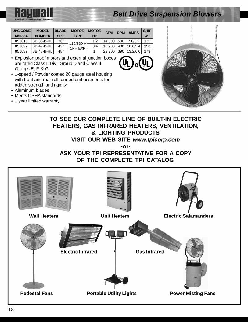
Belt Drive Suspension Blowers
UPC CODE MODEL BLADE MOTOR MOTOR SHIP686334 NUMBER SIZE TYPE HP WT851015 SB-36-B-HL 36" 1/2 14,500 500 7.8/3.9 135851022 SB-42-B-HL 42" 3/4 18,200 430 10.8/5.4 150851039 SB-48-B-HL 48" 1 22,700 390 13.2/6.6 173
CFM RPM AMPS
115/230 V 1PH EXP
• Explosion proof motors and external junction boxesare rated Class I, Div I Group D and Class II,Groups E, F, & G
• 1-speed / Powder coated 20 gauge steel housingwith front and rear roll formed embossments foradded strength and rigidity
• Aluminum blades• Meets OSHA standards• 1 year limited warranty
TO SEE OUR COMPLETE LINE OF BUILT-IN ELECTRICHEATERS, GAS INFRARED HEATERS, VENTILATION,
& LIGHTING PRODUCTSVISIT OUR WEB SITE www.tpicorp.com
-or-ASK YOUR TPI REPRESENTATIVE FOR A COPY
OF THE COMPLETE TPI CATALOG.
Pedestal Fans Portable Utility Lights Power Misting Fans
Electric Infrared Gas Infrared
Wall Heaters Unit Heaters Electric Salamanders

19
RATING DEFINITIONS:CLASS I: Equipment does not have surface operating temperature in excess of the ignition
temperature of the specific gas or vapor .GROUPC: Atmospheres such as but not limited to acetaldehyde, allyl alcohol, hydrogen sulfide,
ethylene, carbon monoxide, or other gasses or vapors of equivalent hazard.GROUP D: Atmospheres such as but not limited to acetone, alcohol, gasoline, lacquer solvent vapors,
natural gas, propane, or other gases or vapors of equivalent hazard.CLASS II: Equipment does not have surface temperature greater than the ignition temperature of the
specified dust.GROUP E: Atmosphere containing combustible metal dust regardless of resistivity, or other combustible
dust of similar hazard characteristics having resistivity of less than 105 OHM-Centimeter orgreater.
GROUP F: Atmosphere containing carbon black, charcoal, coal, or coke dust.GROUP G: Atmospheres containing combustible dust having resistivity of 105 OHM-Centimeter or greaterDIVISION I: A location in which ignitable concentrations of flammable material exist under normal
operating conditions.DIVISION II: Locations in which flammable materials will normally be confined within closed containers and
escape only in the case of accidental rupture, breakdown or during maintenance operations.Any equipment approved for Division I is automatically also approved for Division II.
Hazardous Location Information
Class I - Gases Combustible and flammable gases and vapors in Class I arearranged into four groups A, B, C, D. Group A gases create themost explosive pressure and therefore are the most difficult tocontain. The groups thereafter are in gradual succession ofvolatility.
Class II - Dust Combustible dusts are divided into Groups E, F, and G.Classification invlolves investigation & testing of the assembledenclosure including clamp joints, clearances, and shaft openings.The blanketing effect of layers of dust, electrical conductivity, andthe ignition temp. of the dust are also evaluated.
Group A - Group D - is the largest group, which includesmany common petroleum products
° C ° F305 581 ° C ° F
465 869Group B -
365 689° C ° F 300 572420 788 480 896429 804 356 689400 752 427 800
399 750385 725
Propylene oxide 449 840 440 824651 1204
Group C - 560 1040405 761
° C ° F 515 959175 347 427 800500 932 413 775160 320490 914 280 536249 480 456 853
280 536225 437421 790220 428
482/632 900/1170516 960288 550220 428260 500450 842427 800472 882530 986
Ignition TemperatureGases include:
Ignition TemperatureGases include:
Acetylene
Gases include:
AcetaldehydeCyclopropane
ButadieneEthylene oxideHydrogen & mfg
(by volume)
Diethyl etherEthyleneDimethyl hydrazine
Ignition Temperature
Gases > 30% hydrogen
AcetoneAlcohol's 1-butanol (butyl) Amyl alcohol Butyl alcohol (ter) Ethanol (ethyl) Isobutyl alcohol Isopropyl alcohol Methanol (methyl) Propyl AlcoholAmmoniaBenzene
(100 octane)Heptanes
ButaneEthaneEthyl acetateEthylene dichloride
Vinyl acetateVinyl chlorideXylenes
Methyl ethyl ketonePetroleum naphthaOctanesPentanesPropane
HexanesIsobutyl acetateIsopreneMethane (Nat. gas)
Gasoline (50-60 octane)
Ignition Temperature

20
Limited WarrantyProducts Manufactured by TPI Corporation are warranted to the original consumer to be free fromdefects in material and workmanship for twelve (12) months from the original date of purchase exceptas noted in the Industrial Catalog. The TPI warranty does not cover products modified outside ourfactory, damage or failure caused by acts of God, abuse, misuse, use on other than rated voltage,abnormal usage, faulty installation, failure to provide suggested maintenance procedures by anauthorized TPI Corporation service center.
THERE ARE NO OBLIGATIONS OR LIABILITIES ON THE PART OF TPI CORPORATION FORCONSEQUENTIAL DAMAGES ARISING OUT OF OR IN CONNECTION WITH THE USE ORPERFORMANCE OF THE PRODUCT OR OTHERINDIRECT DAMAGES WITH RESPECT TO LOSSOF PROPERTY, REVENUES, OR PROFIT, OR COSTS OF REMOVAL, INSTALLATION ORREINSTALLATION.
ALL IMPLIED WARRANTIES WITH RESPECT TO TPI PRODUCTS, INCLUDING IMPLIEDWARRANTIES FOR MERCHANTABILITY AMD IMPLIED WARRANTIES FOR FITNESS, ARE LIMITEDIN DURATION TO TWELVE (12) MONTHS FROM ORIGINAL DATE OF PURCHASE, EXCEPT THOSEPRODUCTS OR PARTS OF PRODUCTS WHICH ARE WARRANTED FOR LONGER PERIODS.ON SUCH PRODUCTS OR PARTS OF PRODUCTS ALL IMPLIED WARRANTIES FORMERCHANTIBILITY AND FITNESS ARE LIMITED TO THE DURATION OF THE EXTENDEDWARRANTY PERIOD THEREON.
Some states do not allow the exclusion or limitation of incidental or consequential damages and somestates do not allow limitations on how long an implied warranty lasts, so the above exclusions orlimitations may not apply to you.
During the warranty period, TPI Corporation will, as its sole option, repair or replace any defective partsor products returned, freight prepaid, to the TPI Corporation factory or such other location as TPICorporation may designate. Returned products must be packaged carefully and TPI Corporation shallnot be responsible for damage in transit. When returning parts, the owner must provide the modelnumber of the product and nature of difficulty being experienced. This warranty does not obligate TPICorporation to bear the cost of labor in replacing any assembly, unit or component part thereof, nordoes the company assume any liability for secondary charges, expenses for installation or removal,freight or damages. There will be charges rendered for product repairs made after our warranty periodhas expired. Proof of purchase, including date, must accompany request of in warranty service. In anyevent, TPI Corporation’s maximum liability shall not in any case exceed the purchase price for theproduct claimed to be defective. This warranty gives to you specific legal rights and you may haveother rights which may vary from state to state. For the name of your nearest authorized TPI Corporationservice center, please write to TPI Corporation, P.O. Box 4973, Johnson City, Tennessee, 37602.
Requests for returns of non-defective standard stock units may incur testing and repackaging chargesif units are not in like new condition. Requests for returns of special build models will incur additionaldisassembly and scrap charges. Contact factory for details.
Limited Warranty