hayley n. iben james f. o’brien realistic surface crack...
TRANSCRIPT

Hayley N. Hayley N. IbenIben James F. O’Brien James F. O’Brien Hayley N. Hayley N. IbenIben James F. O’Brien James F. O’Brien
SoHyeon Jeong
Computer Graphics Lab. Korea University
Eurographics/ACM SIGGRAPH Symposium on Computer Animation (2006)
• Realistic surface crack patterns
è based on physical methods
• Heuristically user-defined stress field
è controllability

Korea UniversityComputer Graphics Lab. SoHyeon Jeong | 2010 01 26 | # 2KUCG |
Introduction
• Surface crack patterns
§ Example
• Glass, mud, ceramic glass
§ How it occurs?
• Shrinkage of the object’s surface areas
‗ Drying of mud
‗ Thermal expansion
• If the stress is too high
è the object cracks Figure 1: A crackle class dragon, generated by uniform shrinkage of the surface. This example required 2.7 hours of computation with an input mesh of 75,000 triangles

Korea UniversityComputer Graphics Lab. SoHyeon Jeong | 2010 01 26 | # 3KUCG |
Introduction
• Physically based approaches
• Finite element approach [OH99]
• Virtual node algorithm [MBF04]
§ Second-order dynamic simulation
• Paper’s Approach
§ 1st order quasi-static system (more stable)
§ No dynamics
• Object do NOT move, No collisions, mesh tangling..
§ Stress field
• Defined heuristically
• High tensile stress è Crack occurs è Alleviate stress
xf µ
2atvtx ==
kxF -=

Korea UniversityComputer Graphics Lab. SoHyeon Jeong | 2010 01 26 | # 4KUCG |
Introduction
• The Algorithm ( Based on [OH99] )
§ Where cracks occur
• Existing vertices in triangle mesh
§ How they propagate
• Local re-meshing
• Crack tips are always corresponding to a vertex
• Realism è based on physically correct simulation
• User Controlling è Heuristic parameters

Korea UniversityComputer Graphics Lab. SoHyeon Jeong | 2010 01 26 | # 5KUCG |
2. Background
• Generating Crack Patterns
1. Non-physical approach
2. Physically based methods ( Finite element method + heuristic stress field )
• Modeling in solid materials physically based simulation
§ Terzopoulos et al.
• Elastic deformation [TPBF87]
• Inelastic deformation + fracture [ TF88]
§ Mass-spring system for fracture [NTB91]
§ Finite element for brittle fracture [OH99]
§ Ductile fracture [MG04]
§ Voxelized surface meshes [MTG04]
§ Fracture on elastic and plastic material with virtual node algorithm [MBF-4]
§ Membrane-bending model for thin shells [GSH04]
§ Meshless [PKA05]

Korea UniversityComputer Graphics Lab. SoHyeon Jeong | 2010 01 26 | # 6KUCG |
2. Background
• Surface crack patterns
§ Mass-spring, crack patterns in micro-sphere monolayers [SM88]
§ Tree bark [FP96]
§ A surface [HTK98]
§ Crack a volume [HTK00]
§ Cellular automata to crack multi-layer surfaces [GC00]
§ Peeling off materials [CG01]
§ Paint cracking and peeling using a two-layered model on a 2D grid [PPD02]
§ Wedge-shaped finite element by drying mud and tree bark [FP02][FP04]

Korea UniversityComputer Graphics Lab. SoHyeon Jeong | 2010 01 26 | # 7KUCG |
2. Background
• Non-Physical approaches : (Using input pattern or image )
§ 1. Map some form of a crack pattern to surfaces [MGDA04][DGA05]
• è carves out a volume to generate crack depth
§ 2. Replicate Batik painting crack [WvOC04]
or create cracks similar to an input image [Mou05]
• Fracture Mechanics
§ Extensively studied in engineering or the failure of materials
• Overview [And04][Nis97]
• Drying mud [Kit99]
• Alumina/water slurry [SdBGM00]
• Mud and ceramics [BPC05][BPA*05]

Korea UniversityComputer Graphics Lab. SoHyeon Jeong | 2010 01 26 | # 8KUCG |
3. Stress, Forces and the Separation Tensor
• Previous Approaches [OH99][OBH02][FP04] : 3D Volumes
§ Finite element Discretization + local re-meshing
• Our Method : 2D Triangle Mesh Surfaces
§ Reduced dimension (2D) è Simplifies the simulation computations
§ Heuristically initialized stress field ( FEM x )
• No dynamics (stationary nodes) è No stress occurred
‗ VS Moving nodes [OH99][HTK00][FP04][MBF04]
• User controls over the resulting crack patterns
• Decreased stress computation costs
• Update Stress field with a first-order quasi-static system

Korea UniversityComputer Graphics Lab. SoHyeon Jeong | 2010 01 26 | # 9KUCG |
3.1 The Algorithm
• Pseudo-code
1. Initialize the stress field
2. Evolve the stress field with relaxation
3. Compute the failure criteria(start crack) for each vertex
1. Store this criteria in a priority queue
4. If failure can occur and we want to continue
1. Crack the mesh at the node (the top of the queue)
2. Evolve the stress field
1. Relaxation
2. Optional : Add shrinkage tension and curvature biasing
3. Update the mesh information and queue
5. Display (post-processing)
1. Moving vertices to give the cracks with and filling in the gaps
2. Directly rendered crack edges

Korea UniversityComputer Graphics Lab. SoHyeon Jeong | 2010 01 26 | # 10KUCG |
3.2 Stress Field
• Strain (n x n matrix)
§ The local deformation of the material
• Stress (n x n matrix)
§ The forces internal to the material
§ The eigen value for each eigen vector
• 0 : no stress , > 0 : tensile , < 0 : compressive
§ Ex) – in i-direction, + : in j-direction
iu
ju
ijji
ij ux
ux de -÷
÷ø
öççè
æ
¶¶
׶¶
=
ix
jx
åå= =
=n
k
n
lklijklC
1 1es

Korea UniversityComputer Graphics Lab. SoHyeon Jeong | 2010 01 26 | # 11KUCG |
3.2 Stress Field
• Constant Stress Field
§ Uniform force distribution
over the area
• Heuristic controlling
§ High curvature
• More prone to cracks
§ Manually specified
• Area of high tensions
§ Random noise
• Inhomogeneous
Figure 3: Cracks generated from initializing the stress fieldwith a pattern modeling impacts in flat glass. The field isevolved by the relaxation process, causing the cracks topropagate. Total computation time was 20 seconds with aninput mesh of 4,804 triangles

Korea UniversityComputer Graphics Lab. SoHyeon Jeong | 2010 01 26 | # 12KUCG |
Curvature based Stress Field
Figure 4: Curvature can be used to control crack formation, as demonstrated by the image on the left requiring 3.2 hours computation. Notice the high concentration of cracks around areas of high curvature, such as the ears, neck and leg. The right image was simulated using only uniform shrinkage of the surface, resulting in more evenly spaced cracks and requiring 2.5 hours. The input mesh size was 51,382 triangles for both examples.
With curvatures Uniform shrinkage

Korea UniversityComputer Graphics Lab. SoHyeon Jeong | 2010 01 26 | # 13KUCG |
Figures 2 and 10
Figure 10: Another example of an artistic effect achieved by using curvature to bias the concentration of cracks. In this example, the separation tensor was weighted by k21 +k22 where k1 and k2 are the principle curvature values. Computation time was 1.5 hours on a 30,008 element mesh.
Figure 2: As an artistic effect, we initialized the stress fieldto uniform tension with some bias to crack in the principlecurvature directions. The result of using this heuristic isdemonstrated by the vertical cracks of the angel’s arm andthe cracks following the folds of fabric. Total computationtime was 4.0 hours with an input mesh of 105,772 triangles.

Korea UniversityComputer Graphics Lab. SoHyeon Jeong | 2010 01 26 | # 14KUCG |
3.3 Forces
• The force acting on node(vertex) i by an element
• A : the area
• : the barycentric basis matrix
• p : the node’s position in world coordinate
• : the stress tensor
§ Comparison with [OH99]
• 3D Volume tetrahedral VS 2D surface triangle
• Reduced dimension : 4x4 à 3x3 (matrix)
‗ Barycentric matrix
‗ But position vectors and stress matrices are still defined in 3D
klikk l
jlj
ji pAf sbbååå= ==
-=2
1
2
1
3
1][][
s]0[f
]1[f ]2[f
0v
1v
2v
(1)
b
s
Transforming 2d stress in 3d world coordinate

Korea UniversityComputer Graphics Lab. SoHyeon Jeong | 2010 01 26 | # 15KUCG |
3.4 The Separation Tensor
• The separation tensor (3x3 matrix)
§ As presented in [OH99]
• : the sum of the tensile force
• : the sum of the compressive force
• : the outer product of a vector
§ Crack direction
• = The largest tensile force
• the largest Eigen-vector è the normal of the plane
§ If a crack occurs :
• Its Eigen value is larger than toughness
V
÷÷ø
öççè
æ-++-= åå
-+ Î
-
Î
+
}{}{
)()()()(21
ffff
fmfmfmfmV(2)
+f-f
)( fm
shrinkage
t
+n ˆ
úúú
û
ù
êêê
ë
é=
cccbcabcbbbaacabaa
cbam )),,((

Korea UniversityComputer Graphics Lab. SoHyeon Jeong | 2010 01 26 | # 16KUCG |
4. Mesh Updates
Initialize stress field Initialize stress field
User control
1. Shrinkage tension
2. Impact stress-patterns
3. Bias to crack on
high curvatures
User control
1. Shrinkage tension
2. Impact stress-patterns
3. Bias to crack on
high curvatures
Relaxation Relaxation
Propagation of cracks
Crack Initialized in the
mesh at large stress
Propagation of cracks
Crack Initialized in the
mesh at large stress
Evolution
of the stress field
Evolution
of the stress field

Korea UniversityComputer Graphics Lab. SoHyeon Jeong | 2010 01 26 | # 17KUCG |
4.1 Relaxation
• Relaxation
§ Stress evolves according to a first-order relaxation process
§ A diffuse process
§ Tensor quantities : somewhat complex
• VS Scalar values è mesh-based diffusion
§ Redistributing stress from areas of high stress to areas of low stress
• Other relaxation method
§ Smoothing the stress field [GC00]
§ Reducing tensile stress around cracks based on distance to the nearest cracks
[PPD02]
§ Recalculating the equilibrium state adaptively during crack formulation [FP04]

Korea UniversityComputer Graphics Lab. SoHyeon Jeong | 2010 01 26 | # 18KUCG |
4.1 Relaxation
• Virtual Displacement of the nodes
§ Forces exerted on nodes (1) è nodes would be moved by these forces
• But, not actually moving the nodes, to avoid the time-step and stability issues
§ The Force :
• The sum of all forces on node n exerted by the surrounding elements
§ The virtual displacement :
§ Strain : Green’s strain tensor
• Partial derivatives
][][ nn tFp D=D (3)
][nf][nF
÷÷ø
öççè
æ-
¶¶
׶¶
= ijji
ij ux
ux de
21
[ ]å=
=¶¶ 3
1kkjik
j
i pux b

Korea UniversityComputer Graphics Lab. SoHyeon Jeong | 2010 01 26 | # 19KUCG |
4.1 Relaxation
§ The change of strain tensor (derivative with respect to the node positions)
§ The change of stress (linearly proportional to strain)
§ Updating virtual displacement
• Accumulate the stress è update forces è update displacement by (3)
• Periodically, separation tensor is updated è generating cracks
§ Boundary
• Fixed boundary :net force = 0
[ ][ ] [ ] ÷
ø
öçè
æ+=
¶¶ åå
==
3
1
3
121
mmjmirm
mmjmirm
rn
i ppp
bbbbe
[ ][ ]n
n
pp
D¶¶
=Des
sD s ][np
][npDs fV
ppx
ppx
D׶¶
=¶¶×
¶¶
=¶¶
=D=Deeees

Korea UniversityComputer Graphics Lab. SoHyeon Jeong | 2010 01 26 | # 20KUCG |
4.1 Relaxation
• Implementation of stress relaxation
§ A simple forward Euler method
§ Sufficiently fast
• Other method to update the stress field
§ 1. Uniform shrinkage of the object by adding
• C is positive constant factor
• To avoid identically uniform
: The discretization errors
: Explicitly adding randomness to the tensor
sD sintegration
Ic

Korea UniversityComputer Graphics Lab. SoHyeon Jeong | 2010 01 26 | # 21KUCG |
4.1 Relaxation
§ 2. With the object’s curvature
• Principle curvature [CSM03]
• Add curvature tensor to the stress tensor
‗ High curvature è more cracks
• Multiply the separation tensor by a scaling factor
‗ Gaussian curvature, mean curvature or the Frobenius norm of the curvature tensor
§ 3. By initializing appropriately
• An impact varies based on the material
• Ex) glass
‗ high stress radiating outward from the impact point
‗ low stress in the concentric direction
High
low
k kk
curvature 1=k

Korea UniversityComputer Graphics Lab. SoHyeon Jeong | 2010 01 26 | # 22KUCG |
Figure 6
Figure 6: Example of a crackle glaze teapot, generated by initializing the stress field to uniform shrinkage and evolving it by adding uniform tension. This example required 4.9 hours computation with an input mesh of 60,000 triangles.

Korea UniversityComputer Graphics Lab. SoHyeon Jeong | 2010 01 26 | # 23KUCG |
Figure 7
Figure 7: A rendered example of a crackle glaze cup (left) compared to a photograph (right). Our algorithm generates this effect by initializing the stress field to uniform shrinkage over the surface and evolving it with uniform tension. Total computation time was 43 minutes with a 39,611 triangle input mesh.

Korea UniversityComputer Graphics Lab. SoHyeon Jeong | 2010 01 26 | # 24KUCG |
4.2 Generating Cracks
• Priority Queue
§ The largest positive (tensile) eigenvalue of node’s
§ Crack occurs
• Top eigenvalue > material toughness
§ Crack direction
• Perpendicular to the eigenvector
• Creating new edges
§ Intersecting triangles are split
§ Only In the only surrounding elements
surrounding the node [O’B00]
• Back-cracking [OH99] è edge snipping
§ If new free boundary is too close
to a current crack edge
è do not add a new crack edge
+v V
t+n ˆ
++nv
ˆ
Korea UniversityComputer Graphics Lab. SoHyeon Jeong | 2010 01 26 | # 25KUCG |
4.2 Generating Cracks
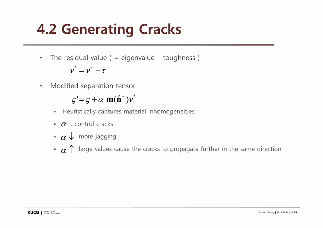
• The residual value ( = eigenvalue – toughness )
• Modified separation tensor
§ Heuristically captures material inhomogeneities
§ : control cracks
§ : more jagging
§ : large values cause the cracks to propagate further in the same direction
t-= +vv*
*)
ˆ(' v++= nmaVV
a¯aa

Korea UniversityComputer Graphics Lab. SoHyeon Jeong | 2010 01 26 | # 26KUCG |
Figure 11: A rendered example of dried mud (left) compared to a photograph (right, copyright 2004 Mayang Adnin). We used uniform shrinkage of the surface and set a = 0.85 to propagate the cracks further, requiring 2.7 minutes computation time on a 19,602 triangle input mesh.
Figure 12: A comparison between rendered dried mud (left) and a photograph (right, copyright 2004 Mayang Adnin). Asin Figure 11, we used uniform shrinkage of the surface, but changed a = 0.5 to demonstrate controlling the crack propagation parameter. Total computation time was 2.0 minutes on a 19,602 triangle input mesh.

Korea UniversityComputer Graphics Lab. SoHyeon Jeong | 2010 01 26 | # 27KUCG |
4.2 Generating Cracks
• Edge Snipping
§ Small or poorly shaped elements è numerical instabilities
§ Snapping close an existing crack edge
• Exceptions
§ Large enough to make artifacts
small enough to generate poorly condition
§ Check singular value of matrix
by SVD
§ è Reconstruct matrix
using restrict the singular value Figure 5: The dotted line (crack plane) gives the location of a new crack. Bold edges are crack edges. Left: After crack edges are added, we locally remesh to ensure all elements are triangles. Middle: Cracks are snapped to an existing edge if q1 is less than a set threshold (ex: 25). Right: Cracks are also snapped to an existing crack edge when q2 is less than a set threshold (ex: 15), avoiding back-cracking.
b
b)( TUDVA =

Korea UniversityComputer Graphics Lab. SoHyeon Jeong | 2010 01 26 | # 28KUCG |
5. Post-Processing
• Rendering cracks
§ Rendering dark lines with a shader [Figures 6 and 7]
§ Creating a visible gap at the crack locations [Figures 3, and 11]
• Change in positions in Eq. (3) (Relaxation process)
• R : the total number of relaxation steps
• : parameter controlling the rate of movement
å=
=DR
inn FTp
1][][ g
g

Korea UniversityComputer Graphics Lab. SoHyeon Jeong | 2010 01 26 | # 29KUCG |
5. Post-Processing
• Curling effects
§ Found in mud and peeling paint
§ Distance : the magnitude of the result from Eq. 9
§ Move the node in the normal direction by a user-defined portion of the
displacement
dnda

Korea UniversityComputer Graphics Lab. SoHyeon Jeong | 2010 01 26 | # 30KUCG |
6. Results and Discussion
• Implementation
§ C++ / Rendered using Pixie
§ Macintosh G5 with 2.5 GB memory
• The running time
§ The mesh resolution
§ Concentration of cracks
• The largest time in the relaxation process
§ Adding cracks increases the size of the mesh
§ But, the simulation time is reasonable

Korea UniversityComputer Graphics Lab. SoHyeon Jeong | 2010 01 26 | # 31KUCG |
6. Results and Discussion
• Various reasons for crack patterns
§ Ceramic [Figure 1] : thermal shock caused by cooling rapidly
• Uniform shrinkage
§ Flat glass struck by an object [Figure 3]
• User-defined stress field
§ Mud drying [Figures 9, 11 and 12]
• Uniform shrinkage, different parameter, and curling effect
§ Object’s geometry [Figure 2, 4 and 10]
• Uniform shrinkage + principle curvature [2]
• Scale factor of the Frobenius norm of the curvature tensor [4]
• The sum of squares of the principle curvature value [19]

Korea UniversityComputer Graphics Lab. SoHyeon Jeong | 2010 01 26 | # 32KUCG |
6. Results and Discussion
• Physically based simulation + traditional appearance driven heuristics
§ Realism + controllability
• Compared with photograph
§ Generated crack patterns have qualitatively similar characteristics to the real ones
• Can be incorporated into an artistic tool
§ By painting a stress field on an object è various cracking results
Figure 8: An animation of mud drying for Figure 11, simulated by setting the stress field to uniform shrinkage of the surface.