harmony your choicesimplified - rs components...
TRANSCRIPT
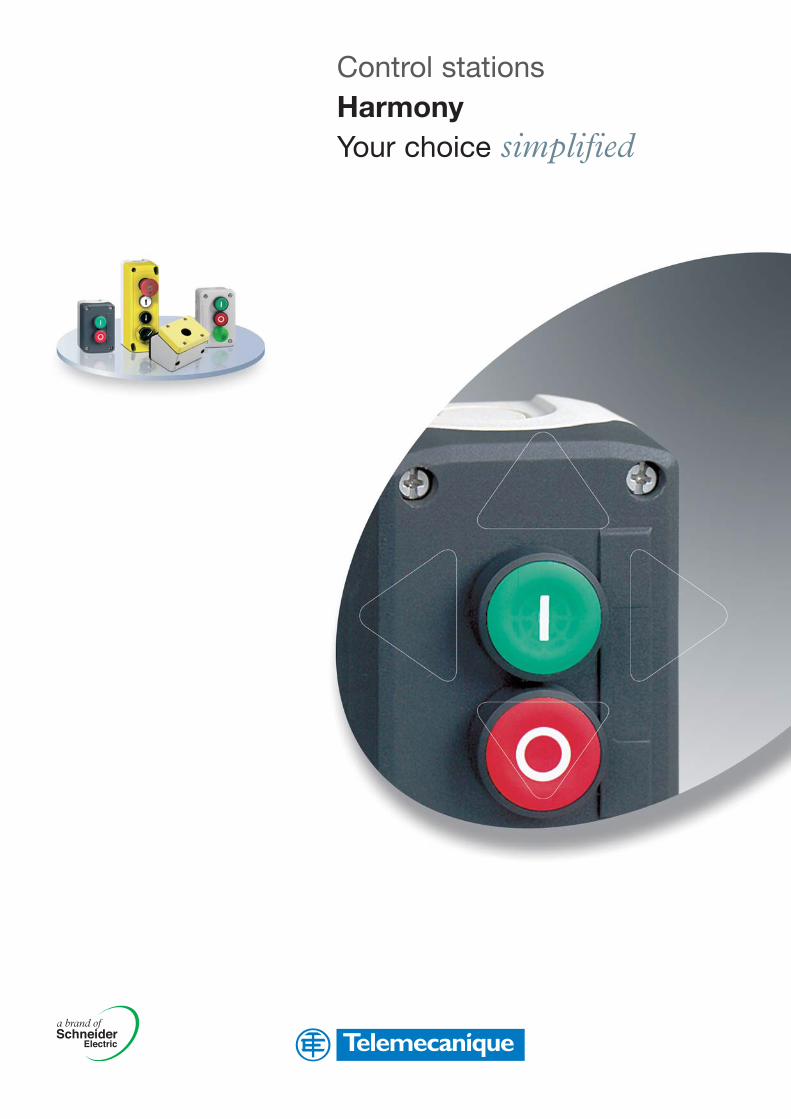
Control stationsHarmonyYour choice simplified
Control stationsHarmonyAn extensive offer...
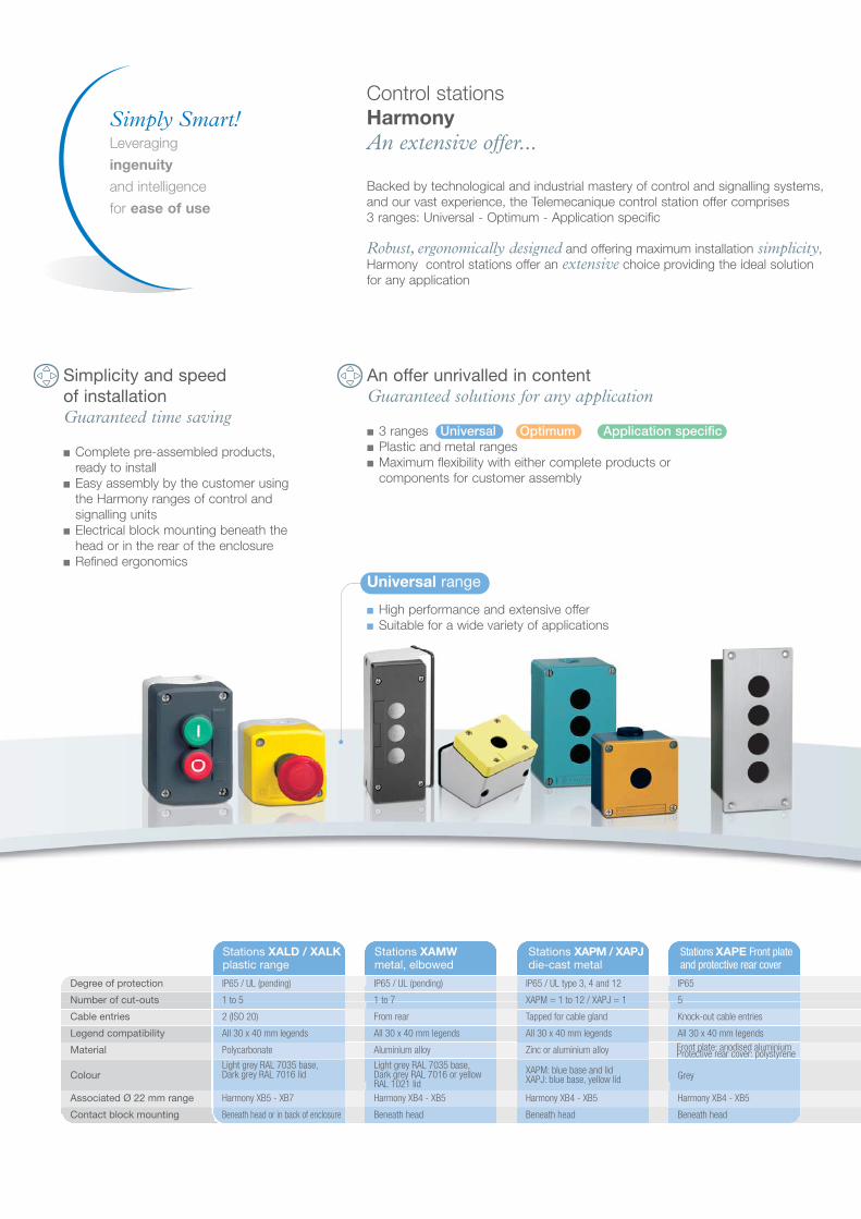
Backed by technological and industrial mastery of control and signalling systems,and our vast experience, the Telemecanique control station offer comprises3 ranges: Universal - Optimum - Application specific
Robust, ergonomically designed and offering maximum installation simplicity,Harmony control stations offer an extensive choice providing the ideal solutionfor any application
Simplicity and speedof installationGuaranteed time saving
■ Complete pre-assembled products, ready to install
■ Easy assembly by the customer using the Harmony ranges of control and signalling units
■ Electrical block mounting beneath the head or in the rear of the enclosure
■ Refined ergonomics
An offer unrivalled in contentGuaranteed solutions for any application
■ 3 ranges Universal Optimum Application specific■ Plastic and metal ranges■ Maximum flexibility with either complete products or
components for customer assembly
Stations XALD / XALKplastic range
Stations XAMWmetal, elbowed
Stations XAPM / XAPJdie-cast metal
Stations XAPE Front plateand protective rear cover
IP65 / UL (pending)
1 to 5
Harmony XB5 - XB7
All 30 x 40 mm legends
Polycarbonate
Light grey RAL 7035 base,Dark grey RAL 7016 lid
2 (ISO 20)
IP65 / UL type 3, 4 and 12
XAPM = 1 to 12 / XAPJ = 1
Harmony XB4 - XB5
All 30 x 40 mm legends
Zinc or aluminium alloy
XAPM: blue base and lidXAPJ: blue base, yellow lid
Beneath head
Tapped for cable gland
IP65 / UL (pending)
1 to 7
Harmony XB4 - XB5
All 30 x 40 mm legends
Aluminium alloy
Light grey RAL 7035 base,Dark grey RAL 7016 or yellowRAL 1021 lid
Beneath head
From rear
IP65
5
Harmony XB4 - XB5
All 30 x 40 mm legends
Grey
Beneath head
Knock-out cable entries
Degree of protection
Number of cut-outs
Associated Ø 22 mm range
Legend compatibility
Material
Cable entries
Colour
Beneath head or in back of enclosure
Front plate: anodised aluminiumProtective rear cover: polystyrene
Contact block mounting
Universal range
■ High performance and extensive offer■ Suitable for a wide variety of applications
Simply Smart!Leveraging
ingenuity
and intelligence
for ease of use

Universal range
High performance and extensive offerSuitable for a wide variety of applications
Modularity■ Wide choice of metal or plastic control stations■ Fully compatible with Harmony metal bezel (XB4) and plastic bezel
(XB5 / XB7) ranges■ Perfect suitability for your needs
• Empty enclosures for customer assembly*• Control stations XAL are also available as a complete, ready to use version
■ 3 electrical blocks (contact or light) in a 53 mm deep station
Robustness■ Used in conjunction with Harmony XB4 range, our metal control stations in
aluminium or zinc alloy, offer an “all metal” solution for unequalled robustness ■ Excellent resistance to corrosion and cleaning agents
Optimum range
Excellent price/performance ratioIdeal for repetitive applications, small machines & simple equipment
Economic■ Complete ready to use stations■ Empty enclosures for customer assembly*■ Legend moulded directly on pushbutton head
Simplicity■ Simple and fast installation using monolithic XB7 E control and signalling units■ Easy selection and ordering
Application specific range
Specific solutions for your most demanding applications
XALG : For applications in severe environmentsPerformance and robustness■ Empty enclosures for customer assembly*■ Mineral reinforced polyamide enclosures and stainless steel fixings
to provide optimum:• Resistance to chemical agents (oil, detergents, chlorine, etc.)• High mechanical integrity (IK05)
■ Tolerant of high pressure cleaning without leakage
XALF : Dedicated to lift maintenancePerformance and safety■ 3 types of station: Pit switch box, hoist way box, top of car box■ Complete ready to use stations, fitted with control and
signalling units from the XB5 or XB7 range■ Empty enclosures for customer assembly*■ Conformity of offer to standards EN 81, EN 418, IEC/EN 60947-1... ■ Specific Emergency stops conform to standards EN 81 and EN 418
• Latching emergency stops with trigger action• Signalling light and mechanical indication throughout 360°
by green ring• Mechanical green/red flag indicator on front face
* Or by Schneider Electric on request
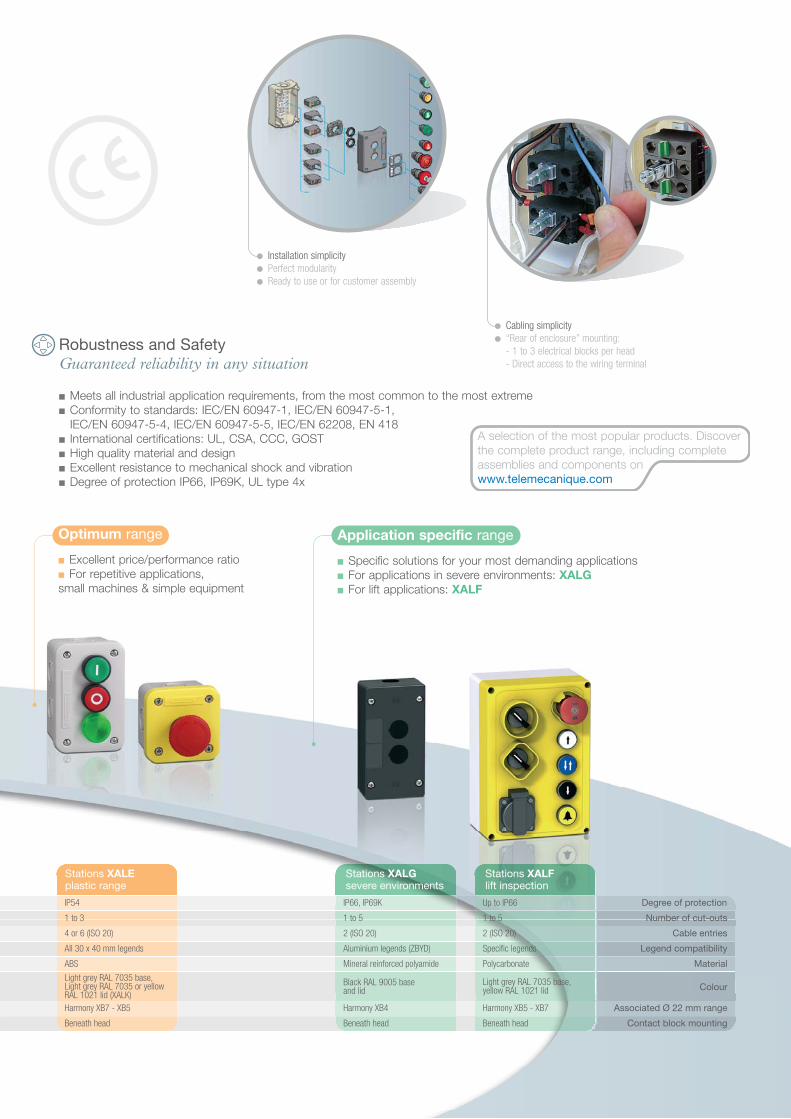
Stations XALEplastic range
Stations XALGsevere environments
Stations XALFlift inspection
IP66, IP69K
1 to 5
Harmony XB4
Aluminium legends (ZBYD)
Mineral reinforced polyamide
Beneath head
2 (ISO 20)
IP54
1 to 3
Harmony XB7 - XB5
All 30 x 40 mm legends
ABS
Light grey RAL 7035 base,Light grey RAL 7035 or yellowRAL 1021 lid (XALK)
Beneath head
4 or 6 (ISO 20)
Up to IP66
1 to 5
Harmony XB5 - XB7
Specific legends
Polycarbonate
Light grey RAL 7035 base,yellow RAL 1021 lid
Beneath head
2 (ISO 20)
Degree of protection
Number of cut-outs
Associated Ø 22 mm range
Legend compatibility
Material
Contact block mounting
Cable entries
ColourBlack RAL 9005 baseand lid
Robustness and SafetyGuaranteed reliability in any situation
■ Meets all industrial application requirements, from the most common to the most extreme■ Conformity to standards: IEC/EN 60947-1, IEC/EN 60947-5-1,
IEC/EN 60947-5-4, IEC/EN 60947-5-5, IEC/EN 62208, EN 418■ International certifications: UL, CSA, CCC, GOST■ High quality material and design■ Excellent resistance to mechanical shock and vibration■ Degree of protection IP66, IP69K, UL type 4x
● Cabling simplicity● “Rear of enclosure” mounting:
- 1 to 3 electrical blocks per head- Direct access to the wiring terminal
Optimum range
■ Excellent price/performance ratio■ For repetitive applications,small machines & simple equipment
Application specific range
■ Specific solutions for your most demanding applications■ For applications in severe environments: XALG■ For lift applications: XALF
● Installation simplicity● Perfect modularity● Ready to use or for customer assembly
A selection of the most popular products. Discoverthe complete product range, including completeassemblies and components onwww.telemecanique.com

(1) Trigger action, with signalling light (white LED) andmechanical indication of status (EN418, EN81)(2) Replace the • by the letter "B" for 24V AC/DC,"G" for 110V AC, "M" for 230V AC depending on the requiredsupply voltage (example: XALFKT6445B11 for 24V AC/DC)
1 cut-out XALG01
2 cut-outs XALG02
3 cut-outs XALG03
4 cut-outs XALG04
5 cut-outs XALG05
Plastic stations, severeenvironment XALG
Emptyenclosures
1 cut-out XALD01
2 cut-outs XALD02
3 cut-outs XALD03
4 cut-outs XALD04
5 cut-outs XALD05
Plastic stationsXALD
Emptyenclosures*
1 cut-out XALE1
2 cut-outs XALE2
3 cut-outs XALE3
Plastic stationsXALE
Emptyenclosures
Emergency stop functionXALEK
1 Emergency stop button 1 N/C XALEK1701
*To order an Emergency stop function empty enclosure (yellow RAL 1021 lid), replace the letter “D” in the reference by the letter “K” (example: XALD01 becomes XALK01)
**Mushroom head Emergency stop buttons conform to standard IEC/EN 60947-5-5. Trigger action mushroom head Emergency stop buttons conform to standard EN 418 and Machinery directive 98/37/EC
1 cut-out XAPM1201
2 cut-outs
80x80mm
80x130mm XAPM2202
Die-cast metal stationsXAPM and XAPJ
Emptyenclosures
1 cut-out (yellow lid) XAPJ1201
3 cut-outs
80x80mm
80x130mm XAPM2203
Plastic stationsXALE
Completestations
1 Flush •• 1 N/O XALE1011
1 Flush •• 1 N/C XALE1112
-
-
1 Flush •• 1 N/O1 Flush •• 1 N/C1 Flush •• 1 N/O1 Flush •• 1 N/O
StartStop XALE2151
XALE2231
1 Flush •• 1 N/O1 Projecting •• 1 N/C1 Flush •• 1 N/O
IOII
XALE3401
1 Flush •• 1 N/O1 Flush •• 1 N/O1 Flush •• 1 N/C
XALE3251
1 Flush •• 1 N/O1 Projecting •• 1 N/C1 Flush •• 1 N/O
XALE3351
2 Pushbuttons
3 Pushbuttons
1 Pushbutton
Turn to release, N/C -XALK174
2 N/C XALK178FXALK174F
N/O + N/C XALK178EXALK174E
1 N/O + 2 N/C XALK178GXALK174G
Key release, N/C -XALK184
2 N/C XALK188FXALK184F
N/O + N/C XALK188EXALK184E
1 N/O + 2 N/C XALK188GXALK184G
Emergency stopstations XALK**
Ø 40 mmpush
Plastic stationsXALD
Completestations
1 Flush •• 1 N/O1 Projecting •• 1 N/C1 Flush •• 1 N/O1 Projecting •• 1 N/C
IO XALD214
1 Flush •• 1 N/O1 Projecting •• 1 N/O XALD222
XALD225
2 Pushbuttons
1 Flush •• 1 N/O1 Flush •• 1 N/C1 Pilot light •• 24V AC/DC
XALD363B
StartStop
3 PushbuttonsIO
1 Flush •• 1 N/O1 Flush •• 1 N/C1 Pilot light •• 24V AC/DC
XALD363MIO
1 Flush •• 1 N/O1 Flush •• 1 N/C1 Flush •• 1 N/O
XALD324
1 Flush •• 1 N/O1 Mushroom head •• 1 N/C1 Flush •• 1 N/O
XALD328
1 cut-out XAMWD01
1 cut-out (yellow lid) XAMWK01
3 cut-outs XAMWD03
2 cut-outs XAMWD02
Aluminium stationsXAMW
Emptyenclosures
Aluminium front plate andprotective rear cover XAPE
Emptyenclosures
1 cut-out, 72x72mm XAPE901
2 cut-outs, 72x105mm
XAPE301
Protective rear coverFront plate
XAPE302 XAPE902
3 cut-outs, 72x138mm XAPE303 XAPE903
• Hoist way box or Pit switch box
• Top of car box
• Hoist way box or Pit switch box
Normal Inspection
Lift inspection stations XALF
XALFKT6445
1 Emergency stop (1) 1 N/O+1 N/C
1 Flush 1 N/O XALFKA2531
1 Flush 1 N/O XALFKA5511
1 Flush 1 N/O XALFKA2521
Pit switch boxes1 Emergency stop (1) 1 N/O+1 N/C
XALFK3010E
Hoist way boxes1 Emergency stop (1) 1 N/O+1 N/C1 Flush 1 N/O1 Flush 1 N/O1 Socket
Top of car boxes1 Emergency stop (1) 1 N/O+1 N/C1 Flush 2 N/O1 Flush 1 N/O1 Flush 2 N/O1 Flush 1 N/O1 Selector switches 3 N/O+3 N/C1 Selector switches 1 N/O+1 N/C "Door"
Open ClosedOff
XALFKT6445•11(2)
XALFP7004E

The efficiency of Telemecanique branded solutionsUsed in combination, Telemecanique products provide quality solutions,meeting all your Automation & Control applications requirements.
A worldwide presenceConstantly available■ More than 5 000 points of sale in 130 countries.■ You can be sure to find the range of products that are right for you andwhich complies fully with the standards in the country where they are used.
Technical assistance wherever you are■ Our technicians are at your disposal to assist you in finding the optimumsolution for your particular needs.■ Schneider Electric provides you with all necessary technical assistance,throughout the world.
www.telemecanique.com
ART.816781
Schneider Electric Industries SAS Simply Smart!
07 / 2006
Head Office
89, bd Franklin Roosevelt
92506 Rueil-Malmaison Cedex
FRANCE
www.schneider-electric.com
Owing to changes in standards and equipment, the characteristics given in the text and images
in this document are not binding until they have been confirmed with us.
Design: www.blueloft.fr
Photos: Schneider Electric
Print:
DIA
4ED
1060
601E
N
Software tools
Motion and Drives
Power supplies
Mounting systems
Interfaces and I/O
Operator dialog
Detection
AutomationMotor control
Systems and architectures
Ø 16 mm
Ø 22 mm
Ø 30 mm
Ø 22 mm
Ø 22 mm
Discover the full Harmony range
Plastic bezel range XB6Range suited to small machinesand tertiary control panels
Metal bezel range XB4Robust range suited toindustrial applications
Plastic bezel range XB5Range resistant to chemicalagents and with doubleinsulation
Plastic bezel range XB7Monolithic offer forsimple machines
9001 K & SK rangeRange suited toheavy industry
Harmony it’s also a complete range of:■ Beacons and indicator banks■ Control stations and enclosures■ Cam switches■ Foot switches
35050-EN_Ver7.3.fm/2
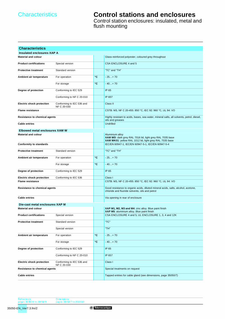
Characteristics 2 Control stations and enclosures 2
Control station enclosures: insulated, metal and flush mounting
CharacteristicsInsulated enclosures XAP A
Material and colour Glass-reinforced polyester, coloured grey throughout
Product certifications Special version CSA ENCLOSURE 4 and 5
Protective treatment Standard version “TC” and “TH”
Ambient air temperature For operation °C - 25…+ 70
For storage °C - 40…+ 70
Degree of protection Conforming to IEC 529 IP 65
Conforming to NF C 20-010 IP 657
Electric shock protection Conforming to IEC 536 and NF C 20-030
Class II
Flame resistance CSTB: M3, NF C 20-455: 850 °C, IEC 92: 960 °C, UL 94: VO
Resistance to chemical agents Highly resistant to acids, bases, sea water, mineral salts, all solvents, petrol, diesel, oils and greases
Cable entries Undrilled
Elbowed metal enclosures XAM WMaterial and colour Aluminium alloy
XAM WD: dark grey RAL 7016 lid, light grey RAL 7035 baseXAM WK01: yellow RAL 1012 lid, light grey RAL 7035 base
Conformity to standards IEC/EN 60947-1, IEC/EN 60947-5-1, IEC/EN 60947-5-4
Protective treatment Standard version “TC” and “TH”
Ambient air temperature For operation °C - 25…+ 70
For storage °C - 40…+ 70
Degree of protection Conforming to IEC 529 IP 65
Electric shock protection Conforming to IEC 536 Class I
Flame resistance CSTB: M3, NF C 20-455: 850 °C, IEC 92: 960 °C, UL 94: VO
Resistance to chemical agents Good resistance to organic acids, diluted mineral acids, salts, alcohol, acetone, chloride and fluoride solvents, oils and petrol
Cable entries Via opening in rear of enclosure
Die-cast metal enclosures XAP MMaterial and colour XAP M1, M2, M3 and M4: zinc alloy. Blue paint finish
XAP M5: aluminium alloy. Blue paint finishProduct certifications Special version CSA ENCLOSURE 4 and 5, UL ENCLOSURE 1, 3, 4 and 12K
Protective treatment Standard version “TC”
Special version “TH”
Ambient air temperature For operation °C - 25…+ 70
For storage °C - 40…+ 70
Degree of protection Conforming to IEC 529 IP 65
Conforming to NF C 20-010 IP 657
Electric shock protection Conforming to IEC 536 and NF C 20-030
Class I
Resistance to chemical agents Special treatments on request
Cable entries Tapped entries for cable gland (see dimensions, page 35050/7)
References:pages 35050/4 to 35050/6
Dimensions:pages 35050/7 to 35050/9

35050-EN_Ver7.3.fm/3
Characteristics (continued) 2 Control stations and enclosures 2
Control station enclosures: insulated, metal and flush mounting
CharacteristicsMetal enclosures XB2 S
Material and colour Aluminium alloy or sheet steel. Blue paint finish
Protective treatment Standard version “TC”
Special version “TH”
Ambient air temperature For operation °C - 25…+ 70
For storage °C - 40…+ 70
Degree of protection Conforming to IEC 529 IP 54
Conforming to NF C 20-010 IP 547
Electric shock protection Conforming to IEC 536 and NF C 20-030
Class I
Resistance to chemical agents Special treatments on request
Cable entries XB2 S in aluminium alloy Tapped entries for cable gland (see dimensions, page 35050/7)
XB2 S in sheet steel Undrilled
Flush mounting enclosures XAP EMaterial and colour Anodised aluminium front plate. Insulated protective rear cover
Protective treatment Standard version “TC” and “TH”
Ambient air temperature For operation °C - 25…+ 70
For storage °C - 40…+ 70
Degree of protection Conforming to IEC 529 IP 65
Conforming to NF C 20-010 IP 657
Electric shock protection Conforming to IEC 536 and NF C 20-030
Class I
Resistance to chemical agents Good resistance to organic acids, diluted mineral acids, salts, alcohol, acetone, chloride and fluoride solvents, oils and petrol
Cable entries Through rear cover: knock-out cable entries
References:pages 35050/4 to 35050/6
Dimensions:pages 35050/7 to 35050/9

35050-EN_Ver7.3.fm/4
References 2 Control stations and enclosures 2
Control station enclosures: insulated, metal and flush mountingWith cut-outs for Ø 22 control and signalling units
ReferencesInsulated enclosures, glass-reinforced polyester (usable depth 83 mm)
Description Front face dimensions mm
Number of cut-outs
Number of rows Reference Weight
kgVertical Horizontal
Without hinges 85 x 146 1 1 1 XAP A1110 0.470
2 1 2 XAP A1120 0.450
4 2 2 XAP A1104 0.460
85 x 226 8 2 4 XAP A2108 0.580
151 x 241 16 4 4 XAP A3116 0.820
With hinges 151 x 241 16 4 4 XAP A4116 0.850
Earthing plates sheet steel with earth screw
For XAP A1110 XAP Z110 0.080
For XAP A1120 XAP Z120 0.070
For XAP A1104 XAP Z104 0.070
For XAP A2108 XAP Z208 0.110
For XAP A3116 and A4116 XAP Z316 0.160
Elbowed metal enclosures for mounting on vertical supportDescription Colour Number of cut-outs Reference Weight
kgElbowed enclosures metal
Dark grey lid (RAL 7016) Light grey base (RAL 7035)
1 XAM WD01 0.465
2 XAM WD02 0.545
3 XAM WD03 0.725
4 XAM WD04 0.725
5 XAM WD05 0.790
6 XAM WD06 0.990
7 XAM WD07 0.990
Yellow lid (RAL 1012)Light grey base (RAL 7035)
1 XAM WK01 0.465
Other versions Insulated and metal control station enclosures with cut-outs for Ø 30 control and signalling units.Protective guards and fixing lugs for die-cast metal enclosures.Insulated and metal control station enclosures pre-fitted with Ø 22 units.Adjustable floor mounting pedestal (790 mm to 1143 mm) for sheet steel enclosures.Please consult your Regional Sales Office.
XAP A1104
XAP A2108
XAP A3116
XAM WD03
XAM WK01
Characteristics:pages 35050/2 and 35050/3
Dimensions:pages 35050/7 to 35050/9

35050-EN_Ver7.3.fm/5
References (continued) 2 Control stations and enclosures 2
Control station enclosures: insulated, metal and flush mountingWith cut-outs for Ø 22 control and signalling units
ReferencesDescription Front face
dimensions mm
Number of cut-outs
Number of rows Reference Weight
kgVertical Horizontal
Die-cast metal enclosures (blue lid and base)
Zinc alloy Usable depth 49 mm
80 x 80 1 1 1 XAP M1201 0.455
2 2 1 XAP M1202 0.450
80 x 130 2 1 2 XAP M2202 0.610
3 1 3 XAP M2203 0.605
4 2 2 XAP M2204 0.600
80 x 175 3 1 3 XAP M3203 0.8704 1 4 XAP M3204 0.880
6 2 3 XAP M3206 0.870
Zinc alloy Usable depth 74.5 mm
80 x 80 1 1 1 XAP M1501 0.605
2 2 1 XAP M1502 0.600
80 x 130 2 1 2 XAP M2502 0.810
3 1 3 XAP M2503 0.815
4 2 2 XAP M2504 0.810
80 x 175 3 1 3 XAP M3503 1.145
4 1 4 XAP M3504 1.140
6 2 3 XAP M3506 1.130
80 x 220 6 1 6 XAP M4506 1.380
8 2 4 XAP M4508 1.370
Aluminium Usable depth 74.5 mm
85 x 310 8 1 8 XAP M5508 0.810
12 2 6 XAP M5512 0.790
Aluminium Usable depth 78 mm
150 x 150 6 3 2 XB2 SL32009 0.970
8 4 2 XB2 SL42009 0.960
Die-cast metal enclosures (yellow lid, blue base)
Zinc alloy Usable depth 49 mm
80 x 80 1 1 1 XAP J1201 0.455
Zinc alloy Usable depth 74.5 mm
80 x 80 1 1 1 XAP J1501 0.605
Sheet steel enclosuresUsable depth 115 mm 200 x 200 8 4 2 XB2 SL42007 3.100
200 x 260 16 4 4 XB2 SL44007 3.900
260 x 260 24 6 4 XB2 SL64007 4.700
260 x 320 30 6 5 XB2 SL65007 5.500
320 x 320 40 8 5 XB2 SL85007 6.200
Other versions Insulated and metal control station enclosures with cut-outs for Ø 30 control and signalling units.Protective guards and fixing lugs for die-cast metal enclosures.Insulated and metal control station enclosures pre-fitted with Ø 30 units.Adjustable floor mounting pedestal (790 mm to 1143 mm) for sheet steel enclosures.Please consult your Regional Sales Office.
XAP M1202
XAP M2504
XB2 SL42009
XB2 SL64007
XAP M4508
XAP M2203
Characteristics:pages 35050/2 and 35050/3
Dimensions:pages 35050/7 to 35050/9

35050-EN_Ver7.3.fm/6
References 2 Control stations and enclosures 2
Control station enclosures: insulated, metal and flush mountingUndrilled or with cut-outs for Ø 22 control and signalling units
ReferencesInsulated enclosures, undrilledDescription Front face
dimensions (mm)Reference Weight
kgUsable depth 83 mm Without hinges 85 x 146 XAP A1100 0.470
85 x 226 XAP A2100 0.600
151 x 241 XAP A3100 0.860
With hinges 151 x 241 XAP A4100 0.890
Earthing plates with earth screw
For XAP A1100 – XAP Z100 0.080
For XAP A2100 – XAP Z200 0.130
For XAP A3100 and A4100 – XAP Z300 0.200
Die-cast metal enclosures, undrilledDescription Material Front face
dimensions (mm)Reference Weight
kgBlue lid and base Zinc alloy
Usable depth 49 mm80 x 80 XAP M11 0.460
80 x 130 XAP M21 0.62080 x 175 XAP M31 0.900
Zinc alloyUsable depth 74.5 mm
80 x 80 XAP M14 0.610
80 x 130 XAP M24 0.830
80 x 175 XAP M34 1.16080 x 220 XAP M44 1.410
AluminiumUsable depth 74.5 mm
85 x 310 XAP M54 0.850
AluminiumUsable depth 78 mm
150 x 150 XB2 SA220095 0.970
Yellow lid, blue base Zinc alloyUsable depth 49 mm
80 x 80 XAP J11 0.460
Zinc alloyUsable depth 74.5 mm
80 x 80 XAP J14 0.610
80 x 175 XAP J34 1.160
Flush mounting enclosures for Ø 22 control and signalling unitsDescription Material Number of
cut-outsFront face dimensions (mm)
Reference Weightkg
Front plates with fixing screws
Aluminium, anodised
1 72 x 72 XAP E301 0.050
2 72 x 105 XAP E302 0.0753 72 x 138 XAP E303 0.095
4 72 x 171 XAP E304 0.115
5 72 x 204 XAP E305 0.135
Protective rear covers Insulated For front plate XAP E301 XAP E901 0.040For front plate XAP E302 XAP E902 0.050
For front plate XAP E303 XAP E903 0.060
For front plate XAP E304 XAP E904 0.070
For front plate XAP E305 XAP E905 0.080
Separate componentsDescription Colour Unit reference Weight
kgBlanking plugswith seal and fixing nut for cut-outs Ø 22.3 mm
Insulated Black ZB2 SZ3 0.005
Grey ZB2 SZ4 0.005
Metal Blue ZB2 SZ2 0.020
Seal (IP 65 degree of protection)(sold in lots of 7)
For mounting Ø 22 control and signalling units in XAM Wp enclosures
ZB2 BZ004 0.001
Other versions Protective guards and fixing lugs for metal enclosures.Flush mounting enclosures, undrilled or with Ø 30 cut-outs.Flush mounting enclosures pre-fitted with Ø 22 units.Please consult your Regional Sales Office.
XAP E301
ZB2 SZ3ZB2 SZ4
ZB2 SZ2
XAP E303 XAP E305
XAP E302
XAP M31XAP M11
XAP A3100
XAP A1100 XAP A2100
+0.40
Characteristics:pages 35050/2 and 35050/3
Dimensions:pages 35050/7 and 35050/9
35050-EN_Ver7.3.fm/7
Dimensions 2 Control stations and enclosures 2
Control station enclosures: insulated, metal and flush mountingWith cut-outs for Ø 22 control and signalling units
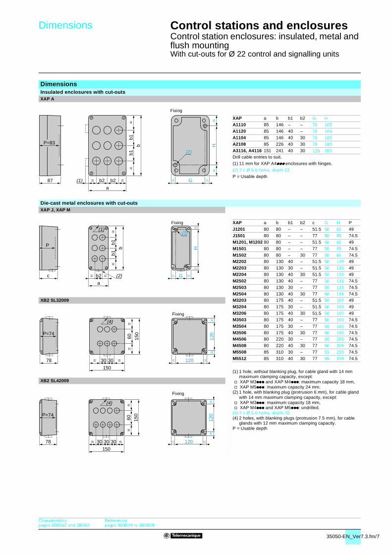
DimensionsInsulated enclosures with cut-outsXAP A
XAP a b b1 b2 G H
A1110 85 146 – – 70 105
A1120 85 146 40 – 70 105
A1104 85 146 40 30 70 105
A2108 85 226 40 30 70 180
A3116, A4116 151 241 40 30 135 200Drill cable entries to suit.
(1) 11 mm for XAP A4ppp enclosures with hinges.
(2) 2 x Ø 5.6 holes, depth 12.
P = Usable depth
Die-cast metal enclosures with cut-outsXAP J, XAP M
XAP a b b1 b2 c G H P
J1201 80 80 – – 51.5 50 65 49
J1501 80 80 – – 77 50 65 74.5
M1201, M1202 80 80 – – 51.5 50 65 49
M1501 80 80 – – 77 50 65 74.5
M1502 80 80 – 30 77 50 65 74.5M2202 80 130 40 – 51.5 50 115 49
M2203 80 130 30 – 51.5 50 115 49
M2204 80 130 40 30 51.5 50 115 49
M2502 80 130 40 – 77 50 115 74.5
M2503 80 130 30 – 77 50 115 74.5
M2504 80 130 40 30 77 50 115 74.5XB2 SL32009 M3203 80 175 40 – 51.5 50 160 49
M3204 80 175 30 – 51.5 50 160 49
M3206 80 175 40 30 51.5 50 160 49
M3503 80 175 40 – 77 50 160 74.5
M3504 80 175 30 – 77 50 160 74.5
M3506 80 175 40 30 77 50 160 74.5M4506 80 220 30 – 77 50 205 74.5
M4508 80 220 40 30 77 50 205 74.5
M5508 85 310 30 – 77 55 295 74.5
M5512 85 310 40 30 77 55 295 74.5
(1) 1 hole, without blanking plug, for cable gland with 14 mm maximum clamping capacity, except:
v XAP M3ppp and XAP M4ppp: maximum capacity 18 mm, v XAP M5ppp: maximum capacity 24 mm.
(2) 1 hole, with blanking plug (protrusion 6 mm), for cable gland with 14 mm maximum clamping capacity, except:
v XAP M3ppp: maximum capacity 18 mm, v XAP M4ppp and XAP M5ppp: undrilled.
(3) 2 x Ø 5.6 holes, depth 20.(4) 2 holes, with blanking plugs (protrusion 7.5 mm), for cable
glands with 12 mm maximum clamping capacity.P = Usable depth
XB2 SL42009
=b1
b1=
b
= =b2 b2
a
(1)
=H
=
= =G
(2)
87
P=83
Fixing
= b2 =
a
=b1
b1=
b
(2)
(1)
= =G
=H
=
(3)
P
c
Fixing
= =3030
150
=60
=
150
(4)
= =120
=12
0=
78
P=74
Fixing
=60
=
150
= =303030
150
(4)
=12
0=
= =120
P=74
78
Fixing
Characteristics:pages 35050/2 and 3505/3
References:pages 35050/4 to 35050/6
35050-EN_Ver7.3.fm/8
Dimensions 2 Control stations and enclosures 2
Control station enclosures: insulated, metal and flush mountingUndrilled or with cut-outs for Ø 22 control and signalling units
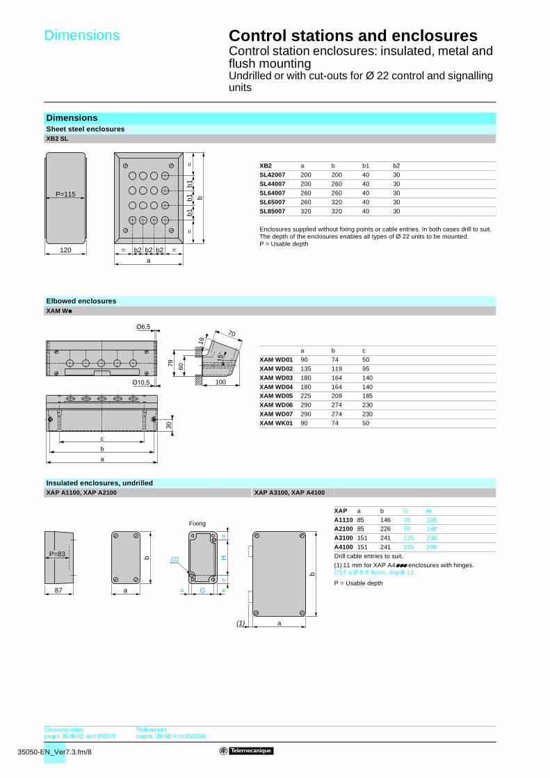
DimensionsSheet steel enclosuresXB2 SL
XB2 a b b1 b2
SL42007 200 200 40 30
SL44007 200 260 40 30
SL64007 260 260 40 30
SL65007 260 320 40 30
SL85007 320 320 40 30
Enclosures supplied without fixing points or cable entries. In both cases drill to suit.The depth of the enclosures enables all types of Ø 22 units to be mounted.P = Usable depth
Elbowed enclosuresXAM Wp
a b c
XAM WD01 90 74 50
XAM WD02 135 119 95
XAM WD03 180 164 140
XAM WD04 180 164 140XAM WD05 225 209 185
XAM WD06 290 274 230
XAM WD07 290 274 230
XAM WK01 90 74 50
Insulated enclosures, undrilledXAP A1100, XAP A2100 XAP A3100, XAP A4100
XAP a b G H
A1110 85 146 70 105A2100 85 226 70 180
A3100 151 241 135 200
A4100 151 241 135 200
Drill cable entries to suit.
(1) 11 mm for XAP A4ppp enclosures with hinges.(2) 2 x Ø 5.6 holes, depth 12.
P = Usable depth
P=115
120 = =b2
a
b2 b2
=b1
b1=
b
b1
30
c
b
a
100
70
6079
19
b
a
=H
=
= =G
(2)
87
P=83
b
a(1)
Fixing
Characteristics:pages 35050/2 and 3505/3
References:pages 35050/4 to 35050/6

35050-EN_Ver7.3.fm/9
Dimensions (continued) 2 Control stations and enclosures 2
Control station enclosures: insulated, metal and flush mountingUndrilled or with cut-outs for Ø 22 control and signalling units
DimensionsDie-cast metal enclosures, undrilledXAP Jpp, XAP Mpp
XAP a b c G H PJ11 80 80 51.5 50 65 49
J14 80 80 77 50 65 74.5
J34 80 175 77 50 160 74.5
M11 80 80 51.5 50 65 49
M14 80 80 77 50 65 74.5
M21 80 130 51.5 50 115 49M24 80 130 77 50 115 74.5
M31 80 175 51.5 50 160 49
M34 80 175 77 50 160 74.5
M44 80 220 77 50 205 74.5
M54 85 310 77 55 295 74.5
(1) 1 hole, without blanking plug, for cable gland with 14 mm maximum clamping capacity, except:
v XAP J34, M31, M34 and M44: maximum capacity 18 mm, v XAP M54: maximum capacity 24 mm.
(2) 1 hole, with blanking plug (protrusion 6 mm), for cable gland with 14 mm maximum clamping capacity, except:
v XAP J34, M31 and M34: maximum capacity 18 mm, v XAP M44, M54: undrilled.
(3) 2 x Ø 5.6 holes, depth 20.(4) 2 holes, with blanking plug (protrusion 7.5 mm), for cable glands
with 12 mm maximum clamping capacity.P = Usable depth
XB2 SA220095
Flush mounting enclosuresXAP E30p
Front plates with cut-outs for Ø 22 control and signalling units
Panel cut-out For Ø 22 control and signalling unitsFront plateXAP b b1 H
E301 72 44 56E302 105 77 89
E303 138 110 122
E304 171 143 155
E305 204 176 188
Mounting of front plate and protective rear cover on support panel
Protective rear cover for front plate XAP E30pXAP b P
E901 52 82.5E902 85 82.5
E903 118 82.5
E904 151 82.5
E905 184 82.5
P = Usable depth
b
a
= =
(1)
(2)c
P
c
P
=H
=
= =G
(3)Fixing
150
150
(4)
= = = =120
=12
0=
78
P=74
Fixing
5
14,5
=H
=
= =56
4 x Ø 4.2
72
= =
=30
=30
30
b H
56
60
b1
4 x M4
80
P b
59
= =
Characteristics:pages 35050/2 and 3505/3
References:pages 35050/4 to 35050/6