hardware manual e84dxxxx 8400 protec stateline-highline-emsdownload.lenze.com/td/e84dxxxx__8400...
TRANSCRIPT
EDS84DPS424.M^h
Ä.M^hä
Hardware Manual
8400 protec 0.75 ... 7.5 kW
�
E84Dxxxxxxx HighLine/StateLine/EMS
Decentralised frequency inverter
L−force Drives

0Fig. 0Tab. 0
Contents i
� 3EDS84DPS424 EN 5.0
1 About this documentation 7. . . . . . . . . . . . . . . . . . . . . . . . . . . . . . . . . . . . . . . . . . . . . . . . . .
1.1 Document history 7. . . . . . . . . . . . . . . . . . . . . . . . . . . . . . . . . . . . . . . . . . . . . . . . . . . .
1.2 Conventions used 8. . . . . . . . . . . . . . . . . . . . . . . . . . . . . . . . . . . . . . . . . . . . . . . . . . . .
1.3 Terms and abbreviations used 9. . . . . . . . . . . . . . . . . . . . . . . . . . . . . . . . . . . . . . . . . .
1.4 Notes used 12. . . . . . . . . . . . . . . . . . . . . . . . . . . . . . . . . . . . . . . . . . . . . . . . . . . . . . . . . .
2 Safety instructions 13. . . . . . . . . . . . . . . . . . . . . . . . . . . . . . . . . . . . . . . . . . . . . . . . . . . . . . . . .
2.1 General safety and application notes for Lenze controllers 13. . . . . . . . . . . . . . . . . .
2.2 General safety and application instructions for Lenze motors 16. . . . . . . . . . . . . . . .
2.3 Residual hazards 19. . . . . . . . . . . . . . . . . . . . . . . . . . . . . . . . . . . . . . . . . . . . . . . . . . . . .
3 Product description 20. . . . . . . . . . . . . . . . . . . . . . . . . . . . . . . . . . . . . . . . . . . . . . . . . . . . . . . .
3.1 Device features 20. . . . . . . . . . . . . . . . . . . . . . . . . . . . . . . . . . . . . . . . . . . . . . . . . . . . . .
3.2 Identification 21. . . . . . . . . . . . . . . . . . . . . . . . . . . . . . . . . . . . . . . . . . . . . . . . . . . . . . . .
3.3 Type code 22. . . . . . . . . . . . . . . . . . . . . . . . . . . . . . . . . . . . . . . . . . . . . . . . . . . . . . . . . .
3.4 Overview of standard devices 25. . . . . . . . . . . . . . . . . . . . . . . . . . . . . . . . . . . . . . . . . .
3.5 Communication 27. . . . . . . . . . . . . . . . . . . . . . . . . . . . . . . . . . . . . . . . . . . . . . . . . . . . . .
3.5.1 CAN port 27. . . . . . . . . . . . . . . . . . . . . . . . . . . . . . . . . . . . . . . . . . . . . . . . . . . .
3.5.2 Infrared remote control receiver 28. . . . . . . . . . . . . . . . . . . . . . . . . . . . . . . . .
3.5.3 Extensions in EMS version 28. . . . . . . . . . . . . . . . . . . . . . . . . . . . . . . . . . . . . .
3.5.4 Infrared interface 29. . . . . . . . . . . . . . . . . . . . . . . . . . . . . . . . . . . . . . . . . . . . .
3.6 Concepts for the mains connection 30. . . . . . . . . . . . . . . . . . . . . . . . . . . . . . . . . . . . . .
3.6.1 Concepts for the connection of individual axes 30. . . . . . . . . . . . . . . . . . . .
3.6.2 Concepts for the connection of the power bus 32. . . . . . . . . . . . . . . . . . . . .
3.7 EMS mains connection concepts 35. . . . . . . . . . . . . . . . . . . . . . . . . . . . . . . . . . . . . . . .
3.7.1 Half wave (coded) 35. . . . . . . . . . . . . . . . . . . . . . . . . . . . . . . . . . . . . . . . . . . . .
3.7.2 Power wave 36. . . . . . . . . . . . . . . . . . . . . . . . . . . . . . . . . . . . . . . . . . . . . . . . . .
3.7.3 DECA bus 37. . . . . . . . . . . . . . . . . . . . . . . . . . . . . . . . . . . . . . . . . . . . . . . . . . . .
3.7.4 Inductive 38. . . . . . . . . . . . . . . . . . . . . . . . . . . . . . . . . . . . . . . . . . . . . . . . . . . .
4 Technical data 39. . . . . . . . . . . . . . . . . . . . . . . . . . . . . . . . . . . . . . . . . . . . . . . . . . . . . . . . . . . .
4.1 General data and operating conditions 39. . . . . . . . . . . . . . . . . . . . . . . . . . . . . . . . .
4.2 Rated data 46. . . . . . . . . . . . . . . . . . . . . . . . . . . . . . . . . . . . . . . . . . . . . . . . . . . . . . . . . .
4.2.1 Overview 46. . . . . . . . . . . . . . . . . . . . . . . . . . . . . . . . . . . . . . . . . . . . . . . . . . . .
4.2.2 Operation at rated mains voltage 400 V 48. . . . . . . . . . . . . . . . . . . . . . . . . .
4.2.3 Operation at a rated mains voltage of 500 V 51. . . . . . . . . . . . . . . . . . . . . .
4.3 Current characteristics 54. . . . . . . . . . . . . . . . . . . . . . . . . . . . . . . . . . . . . . . . . . . . . . . .
4.4 Overcurrent operation 56. . . . . . . . . . . . . . . . . . . . . . . . . . . . . . . . . . . . . . . . . . . . . . . .
4.5 Terminal description 59. . . . . . . . . . . . . . . . . . . . . . . . . . . . . . . . . . . . . . . . . . . . . . . . . .
Contentsi
� 4 EDS84DPS424 EN 5.0
4.6 Supply concept of control voltage 61. . . . . . . . . . . . . . . . . . . . . . . . . . . . . . . . . . . . . . .
4.6.1 Internal 24 V supply voltage 61. . . . . . . . . . . . . . . . . . . . . . . . . . . . . . . . . . . .
4.6.2 External supply voltage 24 V 62. . . . . . . . . . . . . . . . . . . . . . . . . . . . . . . . . . . .
4.7 Control terminals 64. . . . . . . . . . . . . . . . . . . . . . . . . . . . . . . . . . . . . . . . . . . . . . . . . . . . .
4.7.1 Digital inputs 64. . . . . . . . . . . . . . . . . . . . . . . . . . . . . . . . . . . . . . . . . . . . . . . .
4.7.2 Digital outputs 65. . . . . . . . . . . . . . . . . . . . . . . . . . . . . . . . . . . . . . . . . . . . . . .
4.7.3 Analog inputs 66. . . . . . . . . . . . . . . . . . . . . . . . . . . . . . . . . . . . . . . . . . . . . . . .
4.7.4 Synchronous serial interface (SSI) 66. . . . . . . . . . . . . . . . . . . . . . . . . . . . . . . .
4.7.5 Remote control (IrRC) 66. . . . . . . . . . . . . . . . . . . . . . . . . . . . . . . . . . . . . . . . . .
4.7.6 Interfaces of the EMS version 67. . . . . . . . . . . . . . . . . . . . . . . . . . . . . . . . . . .
4.7.7 Motor holding brake connection 68. . . . . . . . . . . . . . . . . . . . . . . . . . . . . . . .
5 Mechanical installation 70. . . . . . . . . . . . . . . . . . . . . . . . . . . . . . . . . . . . . . . . . . . . . . . . . . . . .
5.1 Important notes 70. . . . . . . . . . . . . . . . . . . . . . . . . . . . . . . . . . . . . . . . . . . . . . . . . . . . . .
5.2 Dimensions 71. . . . . . . . . . . . . . . . . . . . . . . . . . . . . . . . . . . . . . . . . . . . . . . . . . . . . . . . . .
5.3 Mounting clearance 72. . . . . . . . . . . . . . . . . . . . . . . . . . . . . . . . . . . . . . . . . . . . . . . . . . .
6 Electrical installation − HighLine/StateLine version 73. . . . . . . . . . . . . . . . . . . . . . . . . . . . . .
6.1 Important notes 73. . . . . . . . . . . . . . . . . . . . . . . . . . . . . . . . . . . . . . . . . . . . . . . . . . . . . .
6.1.1 Electrical isolation 76. . . . . . . . . . . . . . . . . . . . . . . . . . . . . . . . . . . . . . . . . . . .
6.1.2 Device protection 76. . . . . . . . . . . . . . . . . . . . . . . . . . . . . . . . . . . . . . . . . . . . .
6.1.3 Maximum motor cable length 77. . . . . . . . . . . . . . . . . . . . . . . . . . . . . . . . . .
6.1.4 Motor protection 77. . . . . . . . . . . . . . . . . . . . . . . . . . . . . . . . . . . . . . . . . . . . .
6.2 Safety instructions for the installation according to UL or UR 78. . . . . . . . . . . . . . . .
6.3 Safety instructions for the installation according to UL or UR 79. . . . . . . . . . . . . . . .
6.4 Installation according to EMC (installation of a CE−typical drive system) 80. . . . . . .
6.4.1 Shielding 80. . . . . . . . . . . . . . . . . . . . . . . . . . . . . . . . . . . . . . . . . . . . . . . . . . . .
6.4.2 Motor cable 81. . . . . . . . . . . . . . . . . . . . . . . . . . . . . . . . . . . . . . . . . . . . . . . . . .
6.4.3 Control cables 82. . . . . . . . . . . . . . . . . . . . . . . . . . . . . . . . . . . . . . . . . . . . . . . .
6.4.4 Wiring 83. . . . . . . . . . . . . . . . . . . . . . . . . . . . . . . . . . . . . . . . . . . . . . . . . . . . . .
6.4.5 Detecting and eliminating EMC interferences 85. . . . . . . . . . . . . . . . . . . . .
6.5 Devices in a power range of 0.75 ... 7.5 kW (3/PE AC 400 V) 86. . . . . . . . . . . . . . . . . .
6.5.1 Example circuits 86. . . . . . . . . . . . . . . . . . . . . . . . . . . . . . . . . . . . . . . . . . . . . .
6.5.2 Terminal assignment of the power connections 87. . . . . . . . . . . . . . . . . . .
6.6 Control terminals 92. . . . . . . . . . . . . . . . . . . . . . . . . . . . . . . . . . . . . . . . . . . . . . . . . . . . .
6.6.1 Diagnostics 92. . . . . . . . . . . . . . . . . . . . . . . . . . . . . . . . . . . . . . . . . . . . . . . . . .
6.6.2 Analog input 93. . . . . . . . . . . . . . . . . . . . . . . . . . . . . . . . . . . . . . . . . . . . . . . . .
6.6.3 Digital inputs and outputs 95. . . . . . . . . . . . . . . . . . . . . . . . . . . . . . . . . . . . .
6.6.4 Synchronous serial interface (SSI) 98. . . . . . . . . . . . . . . . . . . . . . . . . . . . . . . .
Contents i
� 5EDS84DPS424 EN 5.0
6.7 Communication 99. . . . . . . . . . . . . . . . . . . . . . . . . . . . . . . . . . . . . . . . . . . . . . . . . . . . . .
6.7.1 PROFINET® / EtherNet/IP� 100. . . . . . . . . . . . . . . . . . . . . . . . . . . . . . . . . . . . .
6.7.2 PROFIBUS® 100. . . . . . . . . . . . . . . . . . . . . . . . . . . . . . . . . . . . . . . . . . . . . . . . . .
6.7.3 CANopen® 101. . . . . . . . . . . . . . . . . . . . . . . . . . . . . . . . . . . . . . . . . . . . . . . . . . .
6.7.4 CAN on board 101. . . . . . . . . . . . . . . . . . . . . . . . . . . . . . . . . . . . . . . . . . . . . . . .
6.8 Safety engineering 102. . . . . . . . . . . . . . . . . . . . . . . . . . . . . . . . . . . . . . . . . . . . . . . . . . .
7 Electrical installation − EMS version 105. . . . . . . . . . . . . . . . . . . . . . . . . . . . . . . . . . . . . . . . . . .
7.1 Important notes 105. . . . . . . . . . . . . . . . . . . . . . . . . . . . . . . . . . . . . . . . . . . . . . . . . . . . . .
7.1.1 Electrical isolation 108. . . . . . . . . . . . . . . . . . . . . . . . . . . . . . . . . . . . . . . . . . . .
7.1.2 Device protection 108. . . . . . . . . . . . . . . . . . . . . . . . . . . . . . . . . . . . . . . . . . . . .
7.1.3 Maximum motor cable length 109. . . . . . . . . . . . . . . . . . . . . . . . . . . . . . . . . .
7.1.4 Motor protection 109. . . . . . . . . . . . . . . . . . . . . . . . . . . . . . . . . . . . . . . . . . . . .
7.2 Safety instructions for the installation according to UL or UR 110. . . . . . . . . . . . . . . .
7.3 Safety instructions for the installation according to UL or UR 111. . . . . . . . . . . . . . . .
7.4 Installation according to EMC (installation of a CE−typical drive system) 112. . . . . . .
7.4.1 Shielding 112. . . . . . . . . . . . . . . . . . . . . . . . . . . . . . . . . . . . . . . . . . . . . . . . . . . .
7.4.2 Motor cable 113. . . . . . . . . . . . . . . . . . . . . . . . . . . . . . . . . . . . . . . . . . . . . . . . . .
7.4.3 Control cables 114. . . . . . . . . . . . . . . . . . . . . . . . . . . . . . . . . . . . . . . . . . . . . . . .
7.4.4 Wiring 115. . . . . . . . . . . . . . . . . . . . . . . . . . . . . . . . . . . . . . . . . . . . . . . . . . . . . .
7.4.5 Detecting and eliminating EMC interferences 117. . . . . . . . . . . . . . . . . . . . .
7.5 Devices in a power range of 0.75 ... 4 kW (3/PE AC 400 V) 118. . . . . . . . . . . . . . . . . . . .
7.5.1 Example circuits 118. . . . . . . . . . . . . . . . . . . . . . . . . . . . . . . . . . . . . . . . . . . . . .
7.5.2 Terminal assignment of the power connections 121. . . . . . . . . . . . . . . . . . .
7.6 Control terminals 127. . . . . . . . . . . . . . . . . . . . . . . . . . . . . . . . . . . . . . . . . . . . . . . . . . . . .
7.6.1 Diagnostics 127. . . . . . . . . . . . . . . . . . . . . . . . . . . . . . . . . . . . . . . . . . . . . . . . . .
7.6.2 Digital inputs and outputs 128. . . . . . . . . . . . . . . . . . . . . . . . . . . . . . . . . . . . .
7.6.3 Synchronous serial interface (SSI) 132. . . . . . . . . . . . . . . . . . . . . . . . . . . . . . . .
7.6.4 Interfaces RS485/422 PLC 133. . . . . . . . . . . . . . . . . . . . . . . . . . . . . . . . . . . . . .
7.6.5 Interfaces RS485 PLC 134. . . . . . . . . . . . . . . . . . . . . . . . . . . . . . . . . . . . . . . . . .
7.6.6 Interfaces RS422 PLC 135. . . . . . . . . . . . . . . . . . . . . . . . . . . . . . . . . . . . . . . . . .
7.7 Communication 136. . . . . . . . . . . . . . . . . . . . . . . . . . . . . . . . . . . . . . . . . . . . . . . . . . . . . .
7.7.1 CANopen 137. . . . . . . . . . . . . . . . . . . . . . . . . . . . . . . . . . . . . . . . . . . . . . . . . . . .
7.7.2 CANopen master PLC 137. . . . . . . . . . . . . . . . . . . . . . . . . . . . . . . . . . . . . . . . . .
8 Commissioning 138. . . . . . . . . . . . . . . . . . . . . . . . . . . . . . . . . . . . . . . . . . . . . . . . . . . . . . . . . . .
8.1 Before switching on 139. . . . . . . . . . . . . . . . . . . . . . . . . . . . . . . . . . . . . . . . . . . . . . . . . .
8.2 Preparing the commissioning procedure 140. . . . . . . . . . . . . . . . . . . . . . . . . . . . . . . . .
8.3 Quick commissioning 143. . . . . . . . . . . . . . . . . . . . . . . . . . . . . . . . . . . . . . . . . . . . . . . . .
8.3.1 Keypad control 144. . . . . . . . . . . . . . . . . . . . . . . . . . . . . . . . . . . . . . . . . . . . . . .
8.3.2 Terminal control 146. . . . . . . . . . . . . . . . . . . . . . . . . . . . . . . . . . . . . . . . . . . . . .
Contentsi
� 6 EDS84DPS424 EN 5.0
9 Braking operation 148. . . . . . . . . . . . . . . . . . . . . . . . . . . . . . . . . . . . . . . . . . . . . . . . . . . . . . . . .
9.1 Braking operation without additional measures 148. . . . . . . . . . . . . . . . . . . . . . . . . . .
9.2 Braking operation with external brake resistor 151. . . . . . . . . . . . . . . . . . . . . . . . . . . .
9.2.1 Selection of the brake resistors 152. . . . . . . . . . . . . . . . . . . . . . . . . . . . . . . . . .
9.2.2 Wiring of brake resistor 153. . . . . . . . . . . . . . . . . . . . . . . . . . . . . . . . . . . . . . . .
9.3 Operation with spring−applied brake 156. . . . . . . . . . . . . . . . . . . . . . . . . . . . . . . . . . . .
9.3.1 Introduction 156. . . . . . . . . . . . . . . . . . . . . . . . . . . . . . . . . . . . . . . . . . . . . . . . .
9.3.2 Wiring 158. . . . . . . . . . . . . . . . . . . . . . . . . . . . . . . . . . . . . . . . . . . . . . . . . . . . . .
10 Diagnostics 159. . . . . . . . . . . . . . . . . . . . . . . . . . . . . . . . . . . . . . . . . . . . . . . . . . . . . . . . . . . . . . .
10.1 Display of operating data, diagnostics 159. . . . . . . . . . . . . . . . . . . . . . . . . . . . . . . . . . .
10.1.1 Status display via controller LEDs 159. . . . . . . . . . . . . . . . . . . . . . . . . . . . . . . .
10.1.2 Extensions in EMS version 161. . . . . . . . . . . . . . . . . . . . . . . . . . . . . . . . . . . . . .
10.1.3 Status display of the safety system via LEDs at the controller 162. . . . . . . .
10.1.4 Drive diagnostics via the integrated display 165. . . . . . . . . . . . . . . . . . . . . . .
10.1.5 Drive diagnostics 170. . . . . . . . . . . . . . . . . . . . . . . . . . . . . . . . . . . . . . . . . . . . .
11 Safety engineering 172. . . . . . . . . . . . . . . . . . . . . . . . . . . . . . . . . . . . . . . . . . . . . . . . . . . . . . . .
11.1 Introduction 172. . . . . . . . . . . . . . . . . . . . . . . . . . . . . . . . . . . . . . . . . . . . . . . . . . . . . . . . .
11.2 Important notes 173. . . . . . . . . . . . . . . . . . . . . . . . . . . . . . . . . . . . . . . . . . . . . . . . . . . . . .
11.3 Overview of safety options 174. . . . . . . . . . . . . . . . . . . . . . . . . . . . . . . . . . . . . . . . . . . .
12 Accessories (overview) 176. . . . . . . . . . . . . . . . . . . . . . . . . . . . . . . . . . . . . . . . . . . . . . . . . . . . .
12.1 Overview 176. . . . . . . . . . . . . . . . . . . . . . . . . . . . . . . . . . . . . . . . . . . . . . . . . . . . . . . . . . . .
12.2 System cables 177. . . . . . . . . . . . . . . . . . . . . . . . . . . . . . . . . . . . . . . . . . . . . . . . . . . . . . . .
12.2.1 Motor cable 177. . . . . . . . . . . . . . . . . . . . . . . . . . . . . . . . . . . . . . . . . . . . . . . . . .
12.2.2 Incremental HTL encoder 179. . . . . . . . . . . . . . . . . . . . . . . . . . . . . . . . . . . . . . .
12.2.3 Connection of external brake resistor 180. . . . . . . . . . . . . . . . . . . . . . . . . . . .
12.2.4 Connection of safety sensors and actuators 181. . . . . . . . . . . . . . . . . . . . . . .
12.3 Memory module 182. . . . . . . . . . . . . . . . . . . . . . . . . . . . . . . . . . . . . . . . . . . . . . . . . . . . .
12.3.1 E84AYM10S 182. . . . . . . . . . . . . . . . . . . . . . . . . . . . . . . . . . . . . . . . . . . . . . . . . .
12.3.2 E84AYM30S 183. . . . . . . . . . . . . . . . . . . . . . . . . . . . . . . . . . . . . . . . . . . . . . . . . .
12.4 Diagnosis terminal 184. . . . . . . . . . . . . . . . . . . . . . . . . . . . . . . . . . . . . . . . . . . . . . . . . . .
12.5 Infrared remote control (IrRC) 185. . . . . . . . . . . . . . . . . . . . . . . . . . . . . . . . . . . . . . . . . .
12.6 External brake resistors 186. . . . . . . . . . . . . . . . . . . . . . . . . . . . . . . . . . . . . . . . . . . . . . .
12.7 Power supply units 187. . . . . . . . . . . . . . . . . . . . . . . . . . . . . . . . . . . . . . . . . . . . . . . . . . .
12.8 EMS accessories 188. . . . . . . . . . . . . . . . . . . . . . . . . . . . . . . . . . . . . . . . . . . . . . . . . . . . . .
13 Appendix 189. . . . . . . . . . . . . . . . . . . . . . . . . . . . . . . . . . . . . . . . . . . . . . . . . . . . . . . . . . . . . . . .
13.1 Declarations and certificates 189. . . . . . . . . . . . . . . . . . . . . . . . . . . . . . . . . . . . . . . . . . .
13.2 Total index 195. . . . . . . . . . . . . . . . . . . . . . . . . . . . . . . . . . . . . . . . . . . . . . . . . . . . . . . . . .
About this documentationDocument history
1
� 7EDS84DPS424 EN 5.0
1 About this documentation
Contents
The hardware manual contains the complete information on the intended use of the 8400protec controllers in the StateLine and HighLine versions.
Validity
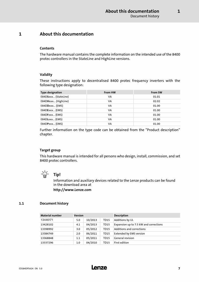
These instructions apply to decentralised 8400 protec frequency inverters with thefollowing type designation:
Type designation From HW From SW
E84DSxxx... (StateLine) VA 01.01
E84DHxxx... (HighLine) VA 02.02
E84DDxxx... (EMS) VA 01.00
E84DExxx... (EMS) VA 01.00
E84DFxxx... (EMS) VA 01.00
E84DLxxx... (EMS) VA 01.00
E84DPxxx... (EMS) VA 01.00
Further information on the type code can be obtained from the "Product description"chapter.
Target group
This hardware manual is intended for all persons who design, install, commission, and set8400 protec controllers.
� Tip!
Information and auxiliary devices related to the Lenze products can be foundin the download area at
http://www.Lenze.com
1.1 Document history
Material number Version Description
.M^h 5.0 10/2013 TD15 Additions by UL
13428102 4.1 04/2013 TD15 Expansion up to 7.5 kW and corrections
13398992 3.0 05/2012 TD15 Additions and corrections
13384749 2.0 06/2011 TD15 Extended by EMS version
13368848 1.1 05/2011 TD15 General revision
13337296 1.0 04/2010 TD15 First edition
About this documentationConventions used
1
� 8 EDS84DPS424 EN 5.0
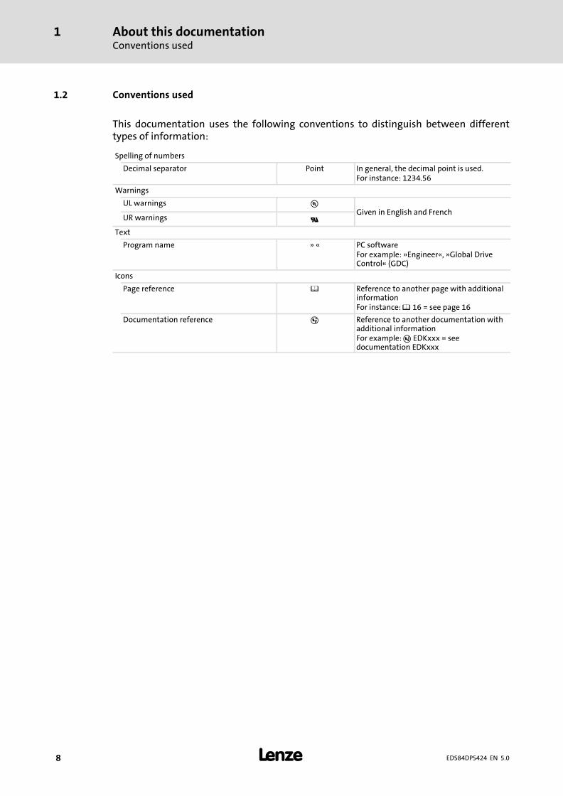
1.2 Conventions used
This documentation uses the following conventions to distinguish between differenttypes of information:
Spelling of numbers
Decimal separator Point In general, the decimal point is used.For instance: 1234.56
Warnings
UL warnings �Given in English and French
UR warnings �
Text
Program name » « PC softwareFor example: »Engineer«, »Global DriveControl« (GDC)
Icons
Page reference � Reference to another page with additionalinformationFor instance: � 16 = see page 16
Documentation reference � Reference to another documentation withadditional informationFor example: � EDKxxx = seedocumentation EDKxxx
About this documentationTerms and abbreviations used
1
� 9EDS84DPS424 EN 5.0
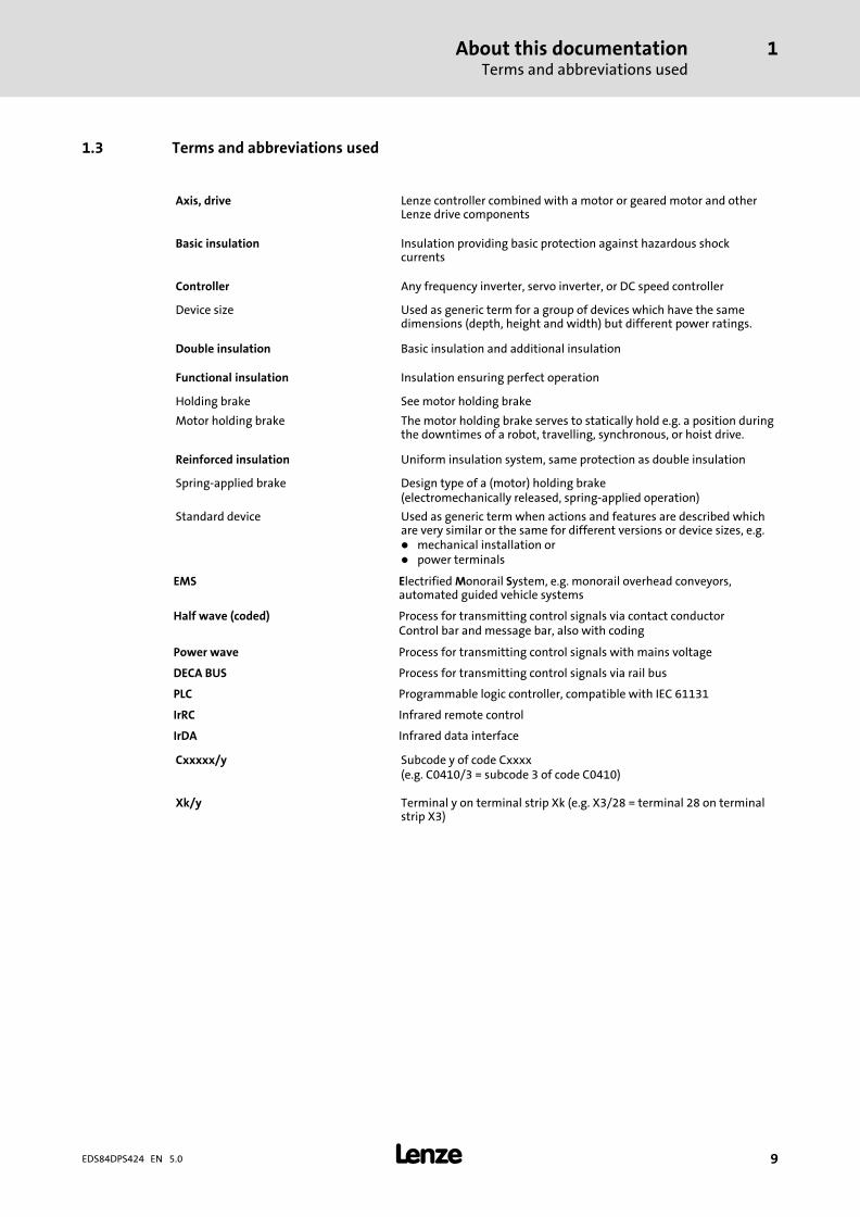
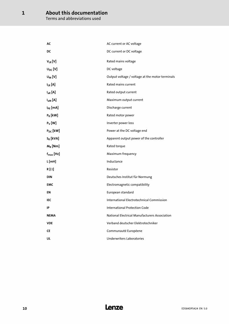
1.3 Terms and abbreviations used
Axis, drive Lenze controller combined with a motor or geared motor and otherLenze drive components
Basic insulation Insulation providing basic protection against hazardous shockcurrents
Controller Any frequency inverter, servo inverter, or DC speed controller
Device size Used as generic term for a group of devices which have the samedimensions (depth, height and width) but different power ratings.
Double insulation Basic insulation and additional insulation
Functional insulation Insulation ensuring perfect operation
Holding brake See motor holding brake
Motor holding brake The motor holding brake serves to statically hold e.g. a position duringthe downtimes of a robot, travelling, synchronous, or hoist drive.
Reinforced insulation Uniform insulation system, same protection as double insulation
Spring−applied brake Design type of a (motor) holding brake(electromechanically released, spring−applied operation)
Standard device Used as generic term when actions and features are described whichare very similar or the same for different versions or device sizes, e.g.� mechanical installation or� power terminals
EMS Electrified Monorail System, e.g. monorail overhead conveyors,automated guided vehicle systems
Half wave (coded) Process for transmitting control signals via contact conductorControl bar and message bar, also with coding
Power wave Process for transmitting control signals with mains voltage
DECA BUS Process for transmitting control signals via rail bus
PLC Programmable logic controller, compatible with IEC 61131
IrRC Infrared remote control
IrDA Infrared data interface
Cxxxxx/y Subcode y of code Cxxxx(e.g. C0410/3 = subcode 3 of code C0410)
Xk/y Terminal y on terminal strip Xk (e.g. X3/28 = terminal 28 on terminalstrip X3)
About this documentationTerms and abbreviations used
1
� 10 EDS84DPS424 EN 5.0
AC AC current or AC voltage
DC DC current or DC voltage
VLR [V] Rated mains voltage
UDC [V] DC voltage
UM [V] Output voltage / voltage at the motor terminals
ILR [A] Rated mains current
IaR [A] Rated output current
IaM [A] Maximum output current
IPE [mA] Discharge current
PR [kW] Rated motor power
PV [W] Inverter power loss
PDC [kW] Power at the DC voltage end
SR [kVA] Apparent output power of the controller
MR [Nm] Rated torque
fmax [Hz] Maximum frequency
L [mH] Inductance
R [�] Resistor
DIN Deutsches Institut für Normung
EMC Electromagnetic compatibility
EN European standard
IEC International Electrotechnical Commission
IP International Protection Code
NEMA National Electrical Manufacturers Association
VDE Verband deutscher Elektrotechniker
CE Communauté Européene
UL Underwriters Laboratories
About this documentationTerms and abbreviations used
1
� 11EDS84DPS424 EN 5.0
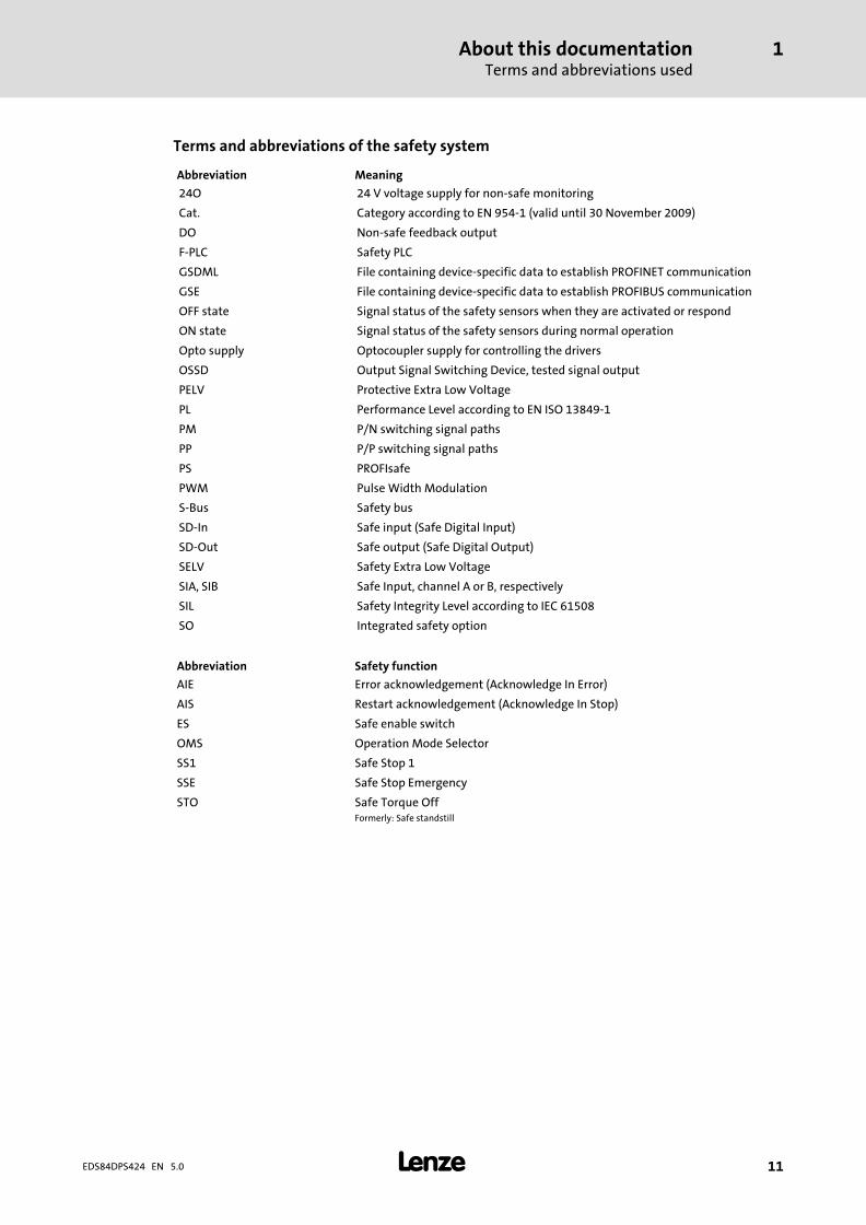
Terms and abbreviations of the safety system
Abbreviation Meaning
24O 24 V voltage supply for non−safe monitoring
Cat. Category according to EN 954−1 (valid until 30 November 2009)
DO Non−safe feedback output
F−PLC Safety PLC
GSDML File containing device−specific data to establish PROFINET communication
GSE File containing device−specific data to establish PROFIBUS communication
OFF state Signal status of the safety sensors when they are activated or respond
ON state Signal status of the safety sensors during normal operation
Opto supply Optocoupler supply for controlling the drivers
OSSD Output Signal Switching Device, tested signal output
PELV Protective Extra Low Voltage
PL Performance Level according to EN ISO 13849−1
PM P/N switching signal paths
PP P/P switching signal paths
PS PROFIsafe
PWM Pulse Width Modulation
S−Bus Safety bus
SD−In Safe input (Safe Digital Input)
SD−Out Safe output (Safe Digital Output)
SELV Safety Extra Low Voltage
SIA, SIB Safe Input, channel A or B, respectively
SIL Safety Integrity Level according to IEC 61508
SO Integrated safety option
Abbreviation Safety function
AIE Error acknowledgement (Acknowledge In Error)
AIS Restart acknowledgement (Acknowledge In Stop)
ES Safe enable switch
OMS Operation Mode Selector
SS1 Safe Stop 1
SSE Safe Stop Emergency
STO Safe Torque OffFormerly: Safe standstill
About this documentationNotes used
1
� 12 EDS84DPS424 EN 5.0
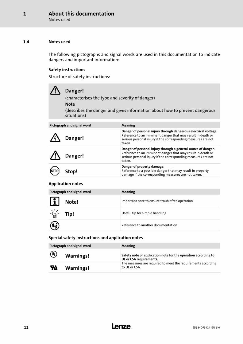
1.4 Notes used
The following pictographs and signal words are used in this documentation to indicatedangers and important information:
Safety instructions
Structure of safety instructions:
� Danger!
(characterises the type and severity of danger)
Note
(describes the danger and gives information about how to prevent dangeroussituations)
Pictograph and signal word Meaning
Danger!
Danger of personal injury through dangerous electrical voltage.Reference to an imminent danger that may result in death orserious personal injury if the corresponding measures are nottaken.
� Danger!
Danger of personal injury through a general source of danger.Reference to an imminent danger that may result in death orserious personal injury if the corresponding measures are nottaken.
Stop!Danger of property damage.Reference to a possible danger that may result in propertydamage if the corresponding measures are not taken.
Application notes
Pictograph and signal word Meaning
� Note! Important note to ensure troublefree operation
� Tip! Useful tip for simple handling
� Reference to another documentation
Special safety instructions and application notes
Pictograph and signal word Meaning
� Warnings! Safety note or application note for the operation according toUL or CSA requirements.The measures are required to meet the requirements accordingto UL or CSA.� Warnings!
Safety instructionsGeneral safety and application notes for Lenze controllers
2
� 13EDS84DPS424 EN 5.0
2 Safety instructions
2.1 General safety and application notes for Lenze controllers
(in accordance with Low−Voltage Directive 2006/95/EC)
For your personal safety
Disregarding the following safety measures can lead to severe injury to persons anddamage to material assets:
ƒ Only use the product as directed.
ƒ Never commission the product in the event of visible damage.
ƒ Never commission the product before assembly has been completed.
ƒ Do not carry out any technical changes on the product.
ƒ Only use the accessories approved for the product.
ƒ Only use original spare parts from Lenze.
ƒ Observe all regulations for the prevention of accidents, directives and lawsapplicable on site.
ƒ Transport, installation, commissioning and maintenance work must only be carriedout by qualified personnel.
– Observe IEC 364 and CENELEC HD 384 or DIN VDE 0100 and IEC report 664 orDIN VDE 0110 and all national regulations for the prevention of accidents.
– According to this basic safety information, qualified, skilled personnel are personswho are familiar with the assembly, installation, commissioning, and operation ofthe product and who have the qualifications necessary for their occupation.
ƒ Observe all specifications in this documentation.
– This is the condition for safe and trouble−free operation and the achievement ofthe specified product features.
– The procedural notes and circuit details described in this documentation are onlyproposals. It’s up to the user to check whether they can be transferred to theparticular applications. Lenze Drives GmbH does not accept any liability for thesuitability of the procedures and circuit proposals described.
ƒ Depending on their degree of protection, some parts of the Lenze controllers(frequency inverters, servo inverters, DC speed controllers) and their accessorycomponents can be live, moving and rotating during operation. Surfaces can be hot.
– Non−authorised removal of the required cover, inappropriate use, incorrectinstallation or operation, creates the risk of severe injury to persons or damage tomaterial assets.
– For more information, please see the documentation.
ƒ High amounts of energy are produced in the controller. Therefore it is required towear personal protective equipment (body protection, headgear, eye protection, earprotection, hand guard).
Safety instructionsGeneral safety and application notes for Lenze controllers
2
� 14 EDS84DPS424 EN 5.0
Application as directed
Controllers are components which are designed for installation in electrical systems ormachines. They are not to be used as domestic appliances, but only for industrial purposesaccording to EN 61000−3−2.
When controllers are installed into machines, commissioning (i.e. starting of the operationas directed) is prohibited until it is proven that the machine complies with the regulationsof the EC Directive 2006/42/EC (Machinery Directive); EN 60204 must be observed.
Commissioning (i.e. starting of the operation as directed) is only allowed when there iscompliance with the EMC Directive (2004/108/EC).
The controllers meet the requirements of the Low−Voltage Directive 2006/95/EC. Theharmonised standard EN 61800−5−1 applies to the controllers.
The technical data and supply conditions can be obtained from the nameplate and thedocumentation. They must be strictly observed.
Warning: Controllers are products which can be installed in drive systems of category C2according to EN 61800−3. These products can cause radio interferences in residential areas.In this case, special measures can be necessary.
Transport, storage
Please observe the notes on transport, storage, and appropriate handling.
Observe the climatic conditions according to the technical data.
Installation
The controllers must be installed and cooled according to the instructions given in thecorresponding documentation.
The ambient air must not exceed degree of pollution 2 according to EN 61800−5−1.
Ensure proper handling and avoid excessive mechanical stress. Do not bend anycomponents and do not change any insulation distances during transport or handling. Donot touch any electronic components and contacts.
Controllers contain electrostatic sensitive devices which can easily be damaged byinappropriate handling. Do not damage or destroy any electrical components since thismight endanger your health!
Electrical connection
When working on live controllers, observe the applicable national regulations for theprevention of accidents (e.g. VBG 4).
The electrical installation must be carried out according to the appropriate regulations(e.g. cable cross−sections, fuses, PE connection). Additional information can be obtainedfrom the documentation.
The documentation provides notes on EMC−compliant installation (shielding, earthing,filter arrangement, and laying of cables). Please also observe these notes when installingCE−labelled controllers. The manufacturer of the machine or plant is responsible for thecompliance with the required limit values associated with EMC legislation.
Lenze controllers may cause a DC current in the PE conductor. If a residual current deviceis used as a protective means in the case of direct or indirect contact with a three−phasecontroller, a residual current device of type B must be used on the current supply side of thecontroller. If the controller has a single−phase supply, it is also permissible to use a residualcurrent device of type A. Apart from the use of a residual current device, other protectivemeasures can also be taken, such as isolation from the environment by double orreinforced insulation, or separation from the supply system by means of a transformer.
Safety instructionsGeneral safety and application notes for Lenze controllers
2
� 15EDS84DPS424 EN 5.0
Operation
If necessary, systems including controllers must be equipped with additional monitoringand protection devices according to the valid safety regulations (e.g. law on technicalequipment, regulations for the prevention of accidents). The controllers can be adapted toyour application. Please observe the corresponding information given in thedocumentation.
After the controller has been disconnected from the supply voltage, all live componentsand power terminals must not be touched immediately because capacitors can still becharged. Please observe the corresponding stickers on the controller.
All protection covers and doors must be shut during operation.
Notes for UL−approved systems with integrated controllers: UL warnings are notes thatonly apply to UL systems. The documentation contains special UL notes.
Safety functions
Certain controller versions support safety functions (e.g. "Safe torque off", formerly "Safestandstill") according to the requirements of the EC Directive "Machinery" 2006/42/EC.The notes provided in the documentation on drive−based safety must be strictly observed.
Maintenance and servicing
The controllers do not require any maintenance if the prescribed operating conditions areobserved.
Disposal
Recycle metal and plastic materials. Ensure professional disposal of assembled PCBs.
The product−specific safety and application notes given in these instructions must beobserved!
Safety instructionsGeneral safety and application instructions for Lenze motors
2
� 16 EDS84DPS424 EN 5.0
2.2 General safety and application instructions for Lenze motors
(According to: Low−Voltage Directive 2006/95/EC)
General
Low−voltage machines have hazardous live and rotating parts and possibly also hotsurfaces.
Synchronous machines induce voltages at open terminals during operation.
All operations concerning transport, connections, commissioning and maintenance mustbe carried out by qualified, skilled personnel (EN 50110−1 (VDE 0105−100) and IEC 60364must be observed). Inappropriate use creates the risk of severe injury to persons anddamage to material assets.
Low−voltage machines may only be operated under the conditions that are indicated in thesection "Application as directed".
The conditions at the place of installation must comply with the data given on thenameplate and in the documentation.
Application as directed
Low−voltage machines are intended for commercial installations. They comply with theharmonised standards of the series EN�60034 (VDE 0530). Their use in potentiallyexplosive atmospheres is prohibited unless they are expressly intended for such use(follow additional instructions).
Low−voltage machines are components for installation into machines as defined in theMachinery Directive 2006/42/EC. Commissioning is prohibited until the conformity of theend product with this directive has been established (follow i.a. EN 60204−1)
Low−voltage machines with IP23 protection or less are only intended for outdoor use whenapplying special protective features.
The integrated brakes must not be used as safety brakes. It cannot be ruled out that factorswhich cannot be influenced, such as oil ingress due to a defective A−side shaft seal, causea brake torque reduction.
Transport, storage
Damages must be reported immediately upon receipt to the forwarder; if required,commissioning must be excluded. Tighten screwed−in ring bolts before transport. They aredesigned for the weight of the low−voltage machines, do not apply extra loads. Ifnecessary, use suitable and adequately dimensioned means of transport (e. g. ropeguides).
Remove transport locking devices before commissioning. Reuse them for furthertransport. When storing low−voltage machines, ensure a dry, dust−free and low−vibration(veff � 0.2 mm/s) environment (damages while being stored).
Safety instructionsGeneral safety and application instructions for Lenze motors
2
� 17EDS84DPS424 EN 5.0
Installation
Ensure an even surface, solid foot and flange mounting and exact alignment if a directclutch is connected. Avoid resonances with the rotational frequency and double mainsfrequency which may be caused by the assembly. Turn rotor by hand, listen for unusualslipping noises. Check the direction of rotation when the clutch is not active (observesection "Electrical connection").
Use appropriate means to mount or remove belt pulleys and clutches (heating) and coverthem with a touch guard. Avoid impermissible belt tensions.
The machines are half−key balanced. The clutch must be half−key balanced, too. The visiblejutting out part of the key must be removed.
If required, provide pipe connections. Designs with shaft end at bottom must be protectedwith a cover which prevents the ingress of foreign particles into the fan. Free circulation ofthe cooling air must be ensured. The exhaust air − also the exhaust air of other machinesnext to the drive system − must not be taken in immediately.
Electrical connection
All operations must only be carried out by qualified and skilled personnel on thelow−voltage machine at standstill and deenergised and provided with a safe guard toprevent an unintentional restart.This also applies to auxiliary circuits (e. g. brake, encoder,blower).
Check safe isolation from supply!
If the tolerances specified in EN 60034−1; IEC 34 (VDE 0530−1) − voltage ±5 %, frequency±2 %, waveform, symmetry − are exceeded, more heat will be generated and theelectromagnetic compatibility will be affected.
Observe the data on the nameplate, operating notes, and the connection diagram in theterminal box.
The connection must ensure a continuous and safe electrical supply (no loose wire ends);use appropriate cable terminals. The connection to the PE conductor must be safe. Theplug−in connector must be bolt tightly (to stop).
The clearances between blank, live parts and to earth must not fall below 8 mm atUr � 550 V, 10 mm at Ur � 725 V, 14 mm at Ur � 1000 V.
The terminal box must be free of foreign particles, dirt and moisture. All unused cableentries and the box itself must be sealed against dust and water.
Safety instructionsGeneral safety and application instructions for Lenze motors
2
� 18 EDS84DPS424 EN 5.0
Commissioning and operation
Before commissioning after longer storage periods, measure the insulation resistance. Incase of values � 1 k� per volt of rated voltage, dry winding.
For trial run without output elements, lock the featherkey. Do not deactivate theprotective devices, not even in a trial run.
Check the correct operation of the brake before commissioning low−voltage machineswith brakes.
Integrated thermal detectors do not provide full protection for the machine. If necessary,limit the maximum current. Parameterise the controller so that the motor will be switchedoff with I > Ir after a few seconds of operation. especially at the risk of blocking.
Vibrational severities veff � 3.5 mm/s (Pr � 15 kW) or 4.5 mm/s (Pr > 15 kW) are acceptableif the clutch is activated.
If deviations from normal operation occur, e.g. increased temperatures, noises, vibrations,find the cause and, if required, contact the manufacturer. In case of doubt, switch off thelow−voltage machine.
If the machine is exposed to dirt, clean the air channels regularly.
Shaft sealing rings and roller bearings have a limited service life.
Regrease bearings with relubricating devices while the low−voltage machine is running.Only use the grease recommended by the manufacturer. If the grease drain holes aresealed with a plug, (IP54 drive end; IP23 drive and non−drive end), remove plug beforecommissioning. Seal bore holes with grease. Replace prelubricated bearings (2Z bearing)after approx. 10,000 h − 20,000 h, at the latest however after 3 − 4 years.
The product−specific safety and application notes given in these instructions must beobserved!
Safety instructionsResidual hazards
2
� 19EDS84DPS424 EN 5.0
2.3 Residual hazards
Protection of persons
ƒ Before working on the controller, check if no voltage is applied to the powerterminals.
ƒ The operating temperature of the heatsink at the controller is very high. Skincontact with the heatsink causes burns. If required, provide for protective covers.
ƒ Before working on the controller, check if no voltage is applied to the powerterminals because
– depending on the device − the power terminals U, V, W, Rb1, and Rb2 remain livefor at least 3 ... 20 minutes after disconnecting the mains.
– the power terminals L1, L2, L3; U, V, W, Rb1, and Rb2 remain live when the motor isstopped.
Device protection
ƒ Frequent switching on of the mains voltage (e.g. inching mode via mains contactor)may overload or destroy the controller.
Motor protection
ƒ Frequent switching on may overheat the connected motor.
ƒ Use PTC thermistors or thermostats with PTC characteristics to monitor the motor.
ƒ Depending on the controller settings, the connected motor can be overheated by:
– For instance, longer DC−braking operations.
– Longer operation of self−ventilated motors at low speed.
Protection of the machine/system
ƒ Drives can reach dangerous overspeeds (e.g. setting of high output frequencies inconnection with motors and machines unsuitable for such conditions):
– The controllers do not offer any protection against such operating conditions. Useadditional components for this purpose.
ƒ Switch contactors in the motor cable only if the controller is inhibited.
When switching contactors in the motor cable while the controller is enabled, you canactivate monitoring functions of the controller. If no monitoring function is activated,switching is permissible.
ƒ All unused connectors must be closed with protection covers or blanking plugs.
Product descriptionDevice features
3
� 20 EDS84DPS424 EN 5.0
3 Product description
3.1 Device features
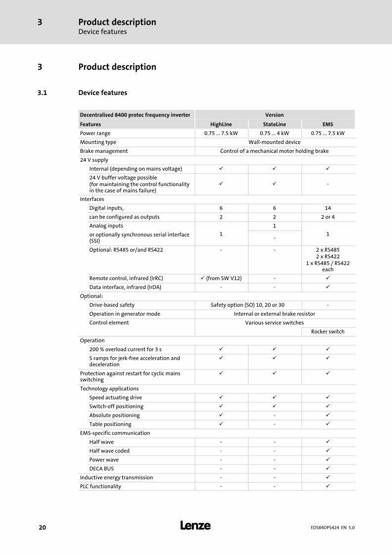
Decentralised 8400 protec frequency inverter Version
Features HighLine StateLine EMS
Power range 0.75 ... 7.5 kW 0.75 ... 4 kW 0.75 ... 7.5 kW
Mounting type Wall−mounted device
Brake management Control of a mechanical motor holding brake
24 V supply
Internal (depending on mains voltage) � � �
24 V buffer voltage possible(for maintaining the control functionalityin the case of mains failure)
� � −
Interfaces
Digital inputs, 6 6 14
can be configured as outputs 2 2 2 or 4
Analog inputs
1
1
1or optionally synchronous serial interface(SSI)
−
Optional: RS485 or/and RS422 − − 2 x RS4852 x RS422
1 x RS485 / RS422each
Remote control, infrared (IrRC) � (from SW V12) − �
Data interface, infrared (IrDA) − − �
Optional:
Drive−based safety Safety option (SO) 10, 20 or 30 −
Operation in generator mode Internal or external brake resistor
Control element Various service switches
Rocker switch
Operation
200 % overload current for 3 s � � �
S ramps for jerk−free acceleration anddeceleration
� � �
Protection against restart for cyclic mainsswitching
� � �
Technology applications
Speed actuating drive � � �
Switch−off positioning � � �
Absolute positioning � − �
Table positioning � − �
EMS−specific communication
Half wave − − �
Half wave coded − − �
Power wave − − �
DECA BUS − − �
Inductive energy transmission − − �
PLC functionality − − �
Product descriptionIdentification
3
� 21EDS84DPS424 EN 5.0
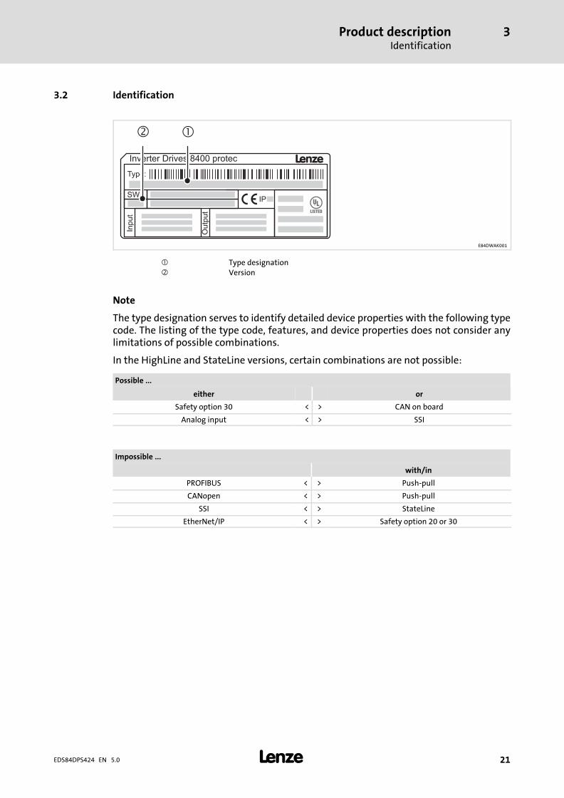
3.2 Identification
LInverter Drives 8400 protec
Outp
ut
Input
SW:
Type:
� �IP
��
E84DWAK001
� Type designation� Version
Note
The type designation serves to identify detailed device properties with the following typecode. The listing of the type code, features, and device properties does not consider anylimitations of possible combinations.
In the HighLine and StateLine versions, certain combinations are not possible:
Possible ...
either or
Safety option 30 < > CAN on board
Analog input < > SSI
Impossible ...
with/in
PROFIBUS < > Push−pull
CANopen < > Push−pull
SSI < > StateLine
EtherNet/IP < > Safety option 20 or 30
Product descriptionType code
3
� 22 EDS84DPS424 EN 5.0
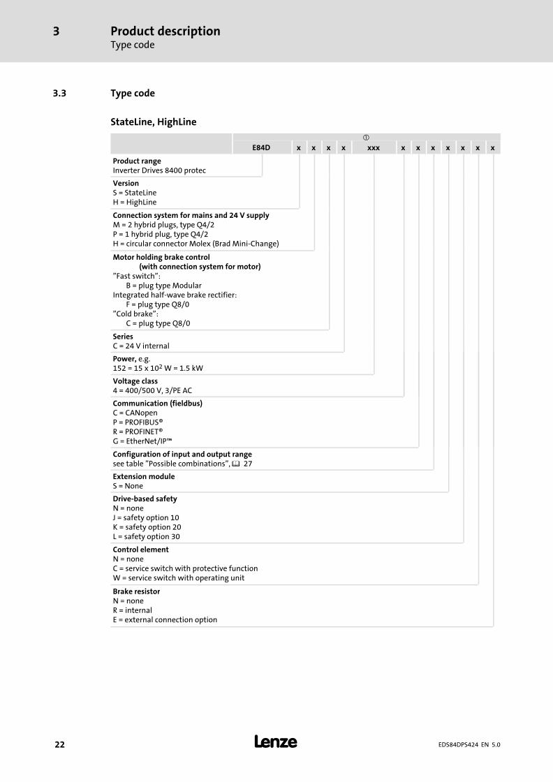
3.3 Type code
StateLine, HighLine
�
E84D x x x x xxx x x x x x x x
Product rangeInverter Drives 8400 protec
VersionS = StateLineH = HighLine
Connection system for mains and 24 V supplyM = 2 hybrid plugs, type Q4/2P = 1 hybrid plug, type Q4/2H = circular connector Molex (Brad Mini−Change)
Motor holding brake control(with connection system for motor)
"Fast switch":B = plug type Modular
Integrated half−wave brake rectifier:F = plug type Q8/0
"Cold brake":C = plug type Q8/0
SeriesC = 24 V internal
Power, e.g.152 = 15 x 102 W = 1.5 kW
Voltage class4 = 400/500 V, 3/PE AC
Communication (fieldbus)C = CANopenP = PROFIBUS®R = PROFINET®G = EtherNet/IP�
Configuration of input and output rangesee table "Possible combinations", � 27
Extension moduleS = None
Drive−based safetyN = noneJ = safety option 10K = safety option 20L = safety option 30
Control elementN = noneC = service switch with protective functionW = service switch with operating unit
Brake resistorN = noneR = internalE = external connection option
Product descriptionType code
3
� 23EDS84DPS424 EN 5.0
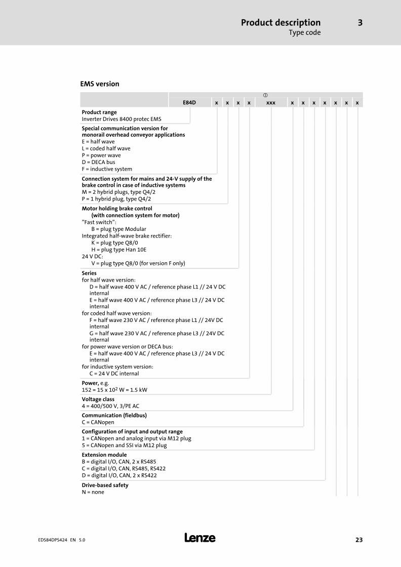
EMS version
�
E84D x x x x xxx x x x x x x x
Product rangeInverter Drives 8400 protec EMS
Special communication version formonorail overhead conveyor applicationsE = half waveL = coded half waveP = power waveD = DECA busF = inductive system
Connection system for mains and 24−V supply of thebrake control in case of inductive systemsM = 2 hybrid plugs, type Q4/2P = 1 hybrid plug, type Q4/2
Motor holding brake control(with connection system for motor)
"Fast switch":B = plug type Modular
Integrated half−wave brake rectifier:K = plug type Q8/0H = plug type Han 10E
24 V DC:V = plug type Q8/0 (for version F only)
Seriesfor half wave version:
D = half wave 400 V AC / reference phase L1 // 24 V DCinternalE = half wave 400 V AC / reference phase L3 // 24 V DCinternal
for coded half wave version:F = half wave 230 V AC / reference phase L1 // 24V DCinternalG = half wave 230 V AC / reference phase L3 // 24V DCinternal
for power wave version or DECA bus:E = half wave 400 V AC / reference phase L3 // 24 V DCinternal
for inductive system version:C = 24 V DC internal
Power, e.g.152 = 15 x 102 W = 1.5 kW
Voltage class4 = 400/500 V, 3/PE AC
Communication (fieldbus)C = CANopen
Configuration of input and output range1 = CANopen and analog input via M12 plug5 = CANopen and SSI via M12 plug
Extension moduleB = digital I/O, CAN, 2 x RS485C = digital I/O, CAN, RS485, RS422D = digital I/O, CAN, 2 x RS422
Drive−based safetyN = none
Product descriptionType code
3
� 24 EDS84DPS424 EN 5.0
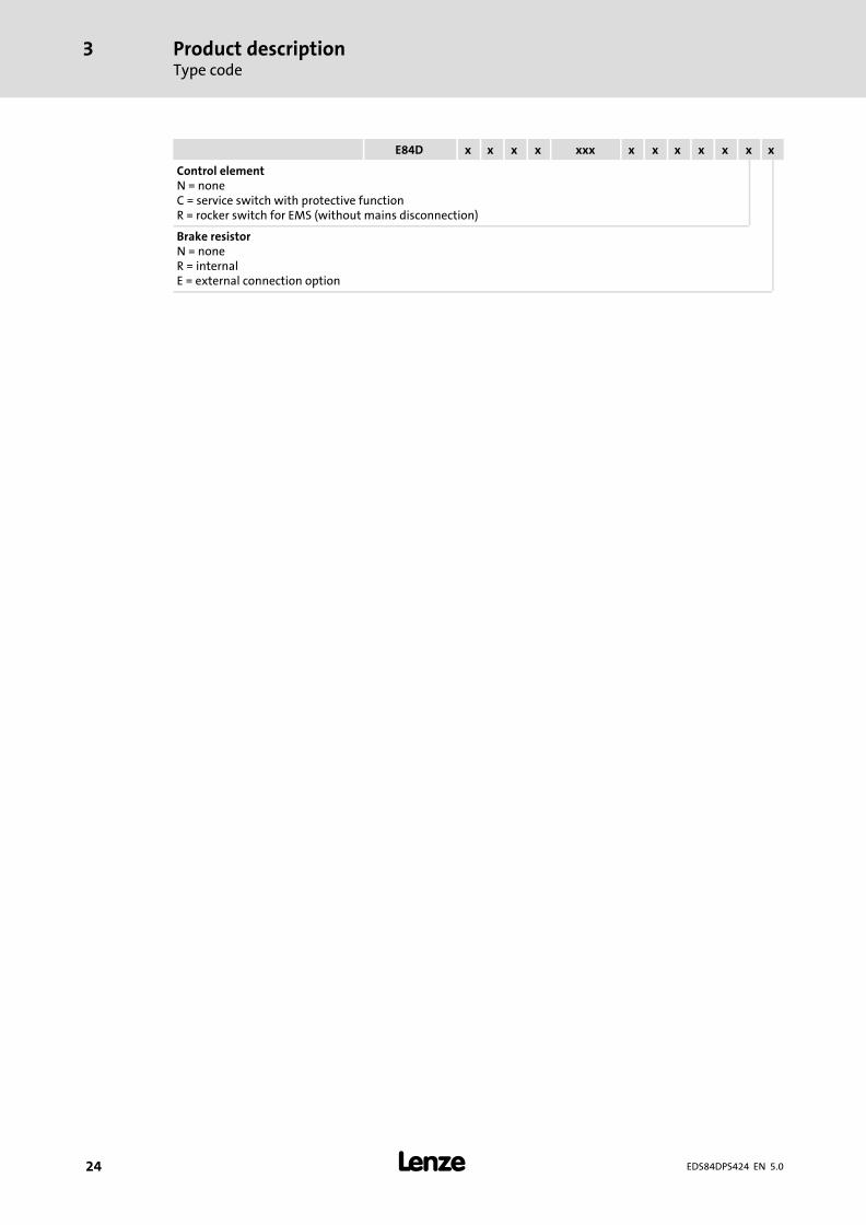
xxxxxxxxxxxxxxE84D
Control elementN = noneC = service switch with protective functionR = rocker switch for EMS (without mains disconnection)
Brake resistorN = noneR = internalE = external connection option
Product descriptionOverview of standard devices
3
� 25EDS84DPS424 EN 5.0
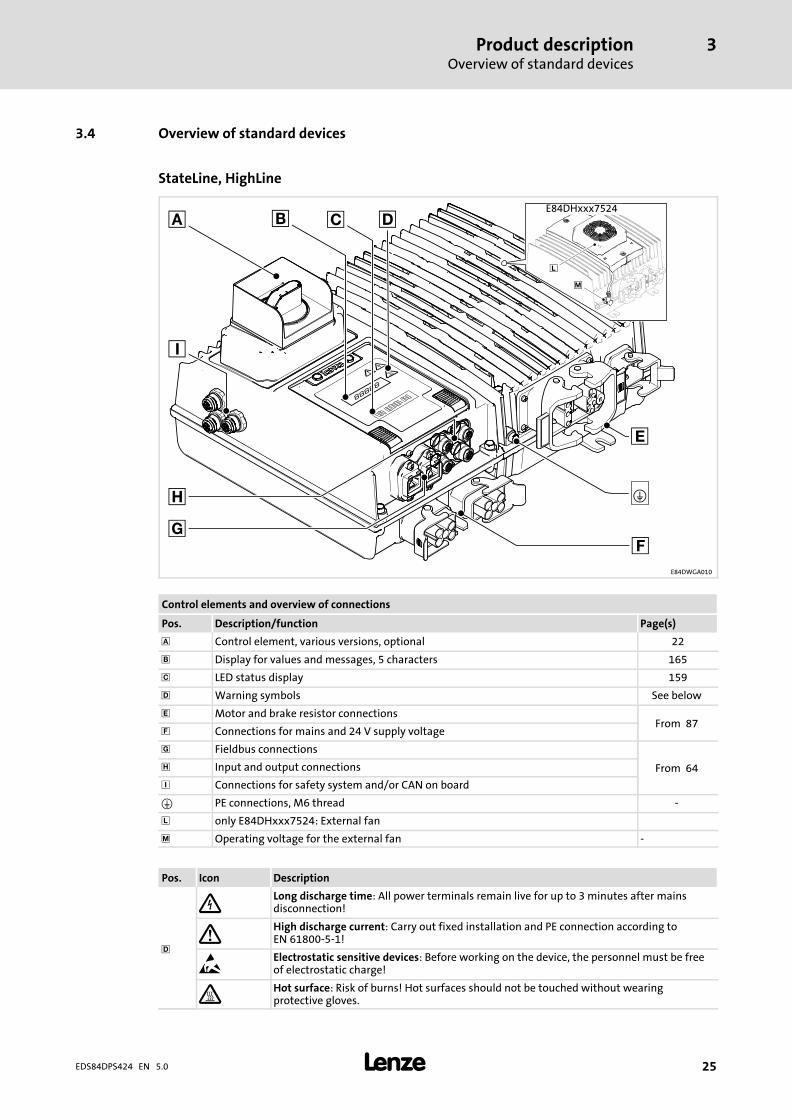
3.4 Overview of standard devices
StateLine, HighLine
E84DWGA010
Control elements and overview of connections
Pos. Description/function Page(s)
� Control element, various versions, optional 22
Display for values and messages, 5 characters 165
� LED status display 159
� Warning symbols See below
� Motor and brake resistor connectionsFrom 87
� Connections for mains and 24 V supply voltage
� Fieldbus connections
From 64� Input and output connections
� Connections for safety system and/or CAN on board
� PE connections, M6 thread −
� only E84DHxxx7524: External fan
� Operating voltage for the external fan −
Pos. Icon Description
�
Long discharge time: All power terminals remain live for up to 3 minutes after mainsdisconnection!
� High discharge current: Carry out fixed installation and PE connection according toEN 61800−5−1!
� Electrostatic sensitive devices: Before working on the device, the personnel must be freeof electrostatic charge!
� Hot surface: Risk of burns! Hot surfaces should not be touched without wearingprotective gloves.
Product descriptionOverview of standard devices
3
� 26 EDS84DPS424 EN 5.0
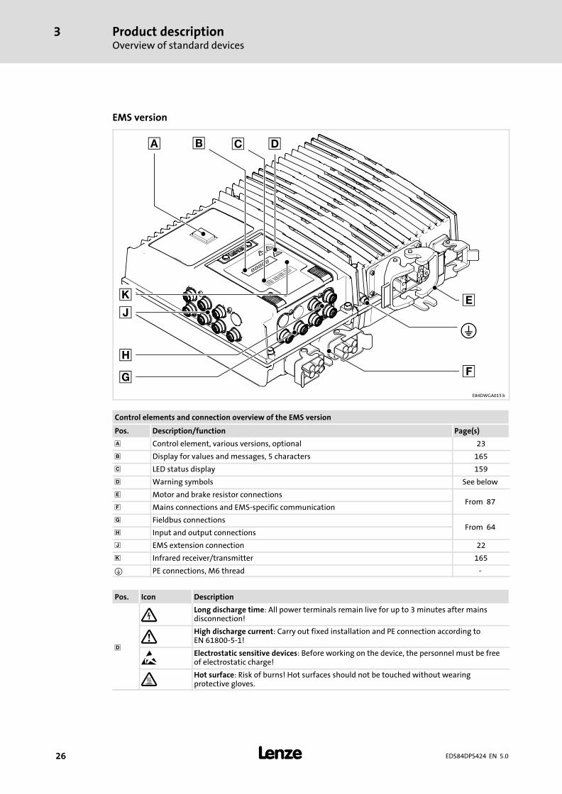
EMS version
E84DWGA015 b
Control elements and connection overview of the EMS version
Pos. Description/function Page(s)
� Control element, various versions, optional 23
Display for values and messages, 5 characters 165
� LED status display 159
� Warning symbols See below
� Motor and brake resistor connectionsFrom 87
� Mains connections and EMS−specific communication
� Fieldbus connectionsFrom 64
� Input and output connections
� EMS extension connection 22
� Infrared receiver/transmitter 165
� PE connections, M6 thread −
Pos. Icon Description
�
Long discharge time: All power terminals remain live for up to 3 minutes after mainsdisconnection!
� High discharge current: Carry out fixed installation and PE connection according toEN 61800−5−1!
� Electrostatic sensitive devices: Before working on the device, the personnel must be freeof electrostatic charge!
� Hot surface: Risk of burns! Hot surfaces should not be touched without wearingprotective gloves.
Product descriptionCommunication
CAN port
3
� 27EDS84DPS424 EN 5.0
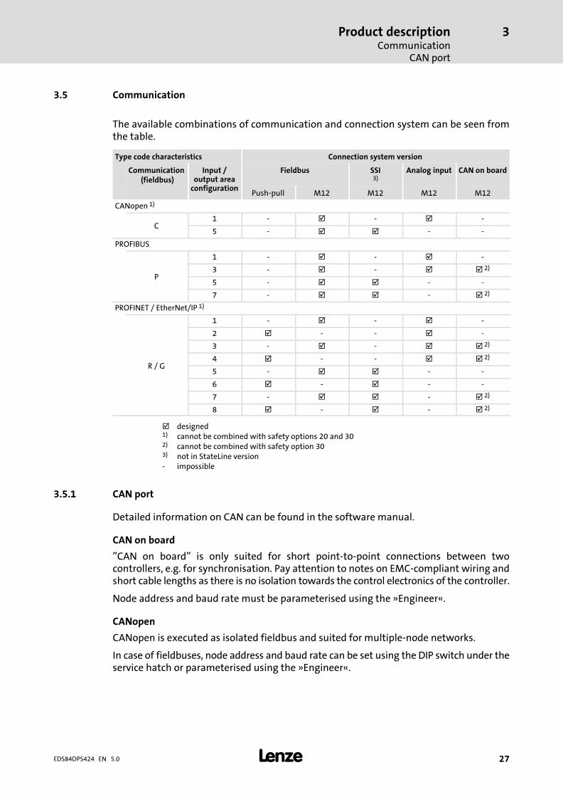
3.5 Communication
The available combinations of communication and connection system can be seen fromthe table.
Type code characteristics Connection system version
Communication (fieldbus)
Input /output area
configuration
Fieldbus SSI3)
Analog input CAN on board
Push−pull M12 M12 M12 M12
CANopen 1)
C1 − � − � −
5 − � � − −
PROFIBUS
P
1 − � − � −
3 − � − � � 2)
5 − � � − −
7 − � � − � 2)
PROFINET / EtherNet/IP 1)
R / G
1 − � − � −
2 � − − � −
3 − � − � � 2)
4 � − − � � 2)
5 − � � − −
6 � − � − −
7 − � � − � 2)
8 � − � − � 2)
� designed1) cannot be combined with safety options 20 and 302) cannot be combined with safety option 303) not in StateLine version− impossible
3.5.1 CAN port
Detailed information on CAN can be found in the software manual.
CAN on board
"CAN on board" is only suited for short point−to−point connections between twocontrollers, e.g. for synchronisation. Pay attention to notes on EMC−compliant wiring andshort cable lengths as there is no isolation towards the control electronics of the controller.
Node address and baud rate must be parameterised using the »Engineer«.
CANopen
CANopen is executed as isolated fieldbus and suited for multiple−node networks.
In case of fieldbuses, node address and baud rate can be set using the DIP switch under theservice hatch or parameterised using the »Engineer«.
Product descriptionCommunicationInfrared remote control receiver
3
� 28 EDS84DPS424 EN 5.0
3.5.2 Infrared remote control receiver
For remote control, the devices are equipped with an infrared receiver (IrRC) (supportedfrom SW version 12 onwards).
The actions enabled by the infrared remote control (LDEZIRRC) are freely programmable.For more information see the software manual and the online help for the LS_IRInterfacesystem block.
� Note!
A trouble−free operation of the optical interface requires:
ƒ Clear line of sight between transmitter and receiver– Maximum distance IrRC: ~ 5 m– Maximum distance IrDA: ~ 1 m– Angle of incidence: ~ 30 °– Avoid direct solar radiation– Environment without interfering transmitter (e.g. from adjacent stations)
ƒ Clean and scratch−free service hatch
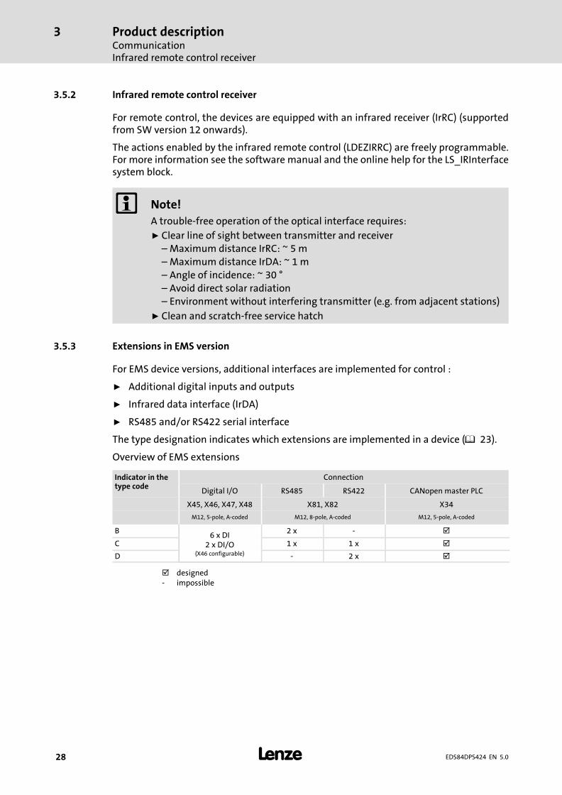
3.5.3 Extensions in EMS version
For EMS device versions, additional interfaces are implemented for control :
ƒ Additional digital inputs and outputs
ƒ Infrared data interface (IrDA)
ƒ RS485 and/or RS422 serial interface
The type designation indicates which extensions are implemented in a device (� 23).
Overview of EMS extensions
Indicator in thetype code
Connection
Digital I/O RS485 RS422 CANopen master PLC
X45, X46, X47, X48 X81, X82 X34
M12, 5−pole, A−coded M12, 8−pole, A−coded M12, 5−pole, A−coded
B6 x DI
2 x DI/O(X46 configurable)
2 x − �
C 1 x 1 x �
D − 2 x �
� designed− impossible
Product descriptionCommunication
Infrared interface
3
� 29EDS84DPS424 EN 5.0
3.5.4 Infrared interface
The EMS versions come with an implemented infrared interface for data transfer (IrDA).
The actions enabled via the interface or the reading of parameter data (codes) are freelyprogrammable in the PLC program.
� Note!
A trouble−free operation of the optical interface requires:
ƒ Clear line of sight between transmitter and receiver– Maximum distance IrRC: ~ 5 m– Maximum distance IrDA: ~ 1 m– Angle of incidence: ~ 30 °– Avoid direct solar radiation– Environment without interfering transmitter (e.g. from adjacent stations)
ƒ Clean and scratch−free service hatch
Product descriptionConcepts for the mains connectionConcepts for the connection of individual axes
3
� 30 EDS84DPS424 EN 5.0
3.6 Concepts for the mains connection
8400 protec controllers support the implementation of various concepts for the mainsconnection. Here, a distinction is drawn between wiring using a:
ƒ Standard cable − commercially available cable
ƒ Hybrid cable − special cable for mains voltage and buffer/control voltage, includingshielding if required
The following must be observed when selecting the wiring:
ƒ Permissible back−up fuse: max. 32 A
ƒ Permissible current for plug contacts 24 V supply: max. 10 A
ƒ Select the cable cross−sections in compliance with applicable standards anddirectives.
– Mains/PE: max. 6 mm2
– 24 V supply: max. 2.5 mm2
3.6.1 Concepts for the connection of individual axes
The following versions are possible according to device version (see type code for mainsconnection system):
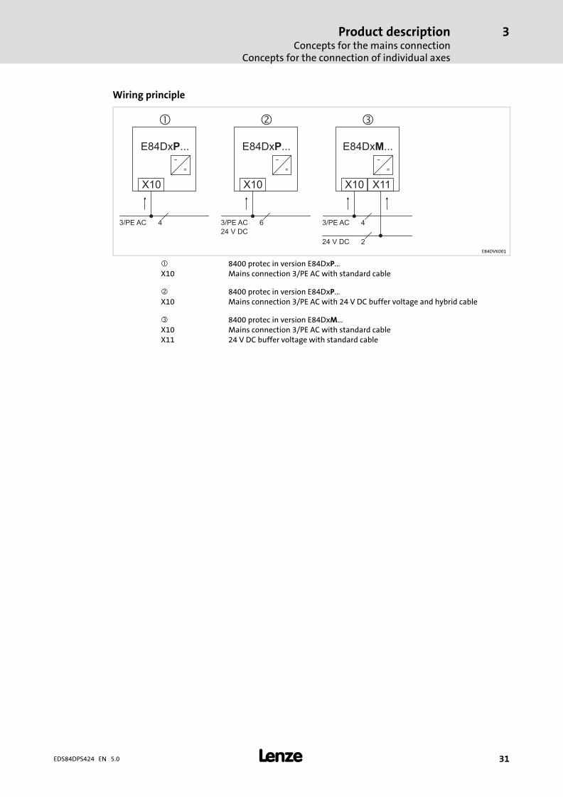
Standard cable �
The mains voltage is connected to the controller by means of a standard cable (plug X10).
The 24 V supply of the controller is generated inside the device (mains−operated supply).After the mains voltage has been switched off, all device functions including the controlelectronics are deactivated. The switch function of Ethernet fieldbuses is also inactive.
Hybrid cable with external 24 V buffer voltage �
The mains voltage and an external 24 V buffer voltage are fed using a hybrid cable (plugX10). Depending on the state of the external 24 V supply, it is possible for the controlelectronics to remain active even if the mains is switched off.
Standard cable with external 24 V buffer voltage �
Since the connector housings only allow for one cable access per Q4/2 connector, theE84DxM... device version (loop−through technique) can be used to implement this conceptfor connection.
Here, the mains voltage is connected to the controller by means of a standard cable (plugX10). The external 24 V buffer voltage is connected by means of a standard cable (plugX11). Depending on the state of the external 24 V supply, it is possible for the controlelectronics to remain active even if the mains is switched off.
� Note!
This concept for connection implies that the mains voltage at plug X10 is alsoapplied at plug X11 at the same time.
Product descriptionConcepts for the mains connection
Concepts for the connection of individual axes
3
� 31EDS84DPS424 EN 5.0
Wiring principle
X10 X11
E84D ...xM
�
43/PE AC
24 V DC 2
X10
E84D ...xP
�
63/PE AC
24 V DC
X10
E84Dx ...P
�
43/PE AC
~ ~ ~
= = =
E84DVK001
� 8400 protec in version E84DxP...X10 Mains connection 3/PE AC with standard cable
� 8400 protec in version E84DxP...X10 Mains connection 3/PE AC with 24 V DC buffer voltage and hybrid cable
� 8400 protec in version E84DxM...X10 Mains connection 3/PE AC with standard cableX11 24 V DC buffer voltage with standard cable
Product descriptionConcepts for the mains connectionConcepts for the connection of the power bus
3
� 32 EDS84DPS424 EN 5.0
3.6.2 Concepts for the connection of the power bus
Spacious plants are often organised in lines. A clearly structured cable routing leads to atypical line topology. Two connection types are used:
ƒ Loop−through technique from device to device
– Here, the mains voltage and the 24 V buffer voltage are applied at X10 and X11 atthe same time.
ƒ Branch of power distributors
Depending on the type of cables and the 24 V supply, the following implementations arepossible.
Possible loop−through arrangements:
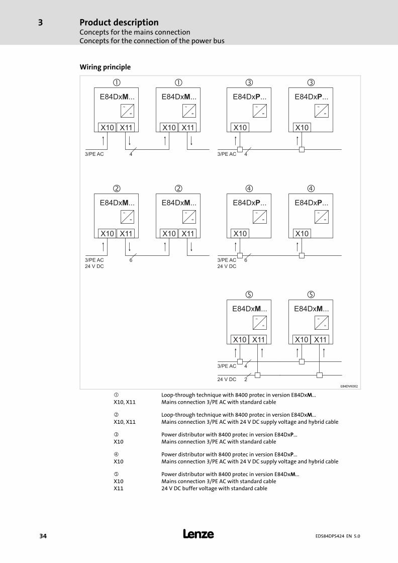
Standard cable �
The mains voltage is distributed among the devices by means of a standard cable (plugsX10 and X11). The 24 V supply of the controller is generated inside the device(mains−operated supply). After the mains voltage has been switched off, all devicefunctions including the control electronics are deactivated. The switch function ofEthernet fieldbuses is also inactive.
Hybrid cable with external 24 V buffer voltage �
The mains voltage and an external 24 V buffer voltage (self−contained) are distributedamong the devices using a cable (plugs X10 and X11). Depending on the state of theexternal 24 V supply, it is possible for the control electronics to remain active even if themains is switched off.
Arrangements including power distributors:
Standard cable including power distributors�
The mains voltage is carried in a cable and distributed to the device by power distributors(plug X10). The 24 V supply of the controller is generated inside the device (mains−operatedsupply). After the mains voltage has been switched off, all device functions including thecontrol electronics are deactivated. The switch function of Ethernet fieldbuses is alsoinactive.
Hybrid cable with power distributors and external 24 V buffer voltage �
The mains voltage and the 24 V buffer voltage are carried in a cable and distributed to thedevice by power distributors (plug X10). Depending on the state of the external 24 Vsupply, it is possible for the control electronics to remain active even if the mains isswitched off.

Product descriptionConcepts for the mains connection
Concepts for the connection of the power bus
3
� 33EDS84DPS424 EN 5.0
Standard cable with power distributors and external 24 V buffer voltage
Isolated cable routing for mains voltage and 24 V buffer voltage.
Here, the mains voltage is connected to the controller by means of a standard cable (plugX10). The external 24 V buffer voltage (self−contained) is connected by means of a standardcable (plug X11). Depending on the state of the external 24 V supply, it is possible for thecontrol electronics to remain active even if the mains is switched off.
Product descriptionConcepts for the mains connectionConcepts for the connection of the power bus
3
� 34 EDS84DPS424 EN 5.0
Wiring principle
X10 X10
� �
43/PE AC
~
=
~
=
~
=
~
=
~
=
~
=
X10 X10
� �
63/PE AC
24 V DC
X10 X10X11 X11
� �
43/PE AC
24 V DC 2
X10 X10X11 X11
� �
63/PE AC
24 V DC
X10 X10X11 X11
� �
43/PE AC
~
=
~
=
~
=
~
=
E84D ...xP E84D ...xPE84D ...xM E84D ...xM
E84D ...xP E84D ...xPE84D ...xM E84D ...xM
E84D ...xM E84D ...xM
E84DVK002
� Loop−through technique with 8400 protec in version E84DxM...X10, X11 Mains connection 3/PE AC with standard cable
� Loop−through technique with 8400 protec in version E84DxM...X10, X11 Mains connection 3/PE AC with 24 V DC supply voltage and hybrid cable
� Power distributor with 8400 protec in version E84DxP...X10 Mains connection 3/PE AC with standard cable
� Power distributor with 8400 protec in version E84DxP...X10 Mains connection 3/PE AC with 24 V DC supply voltage and hybrid cable
Power distributor with 8400 protec in version E84DxM...X10 Mains connection 3/PE AC with standard cableX11 24 V DC buffer voltage with standard cable
Product descriptionEMS mains connection concepts
Half wave (coded)
3
� 35EDS84DPS424 EN 5.0
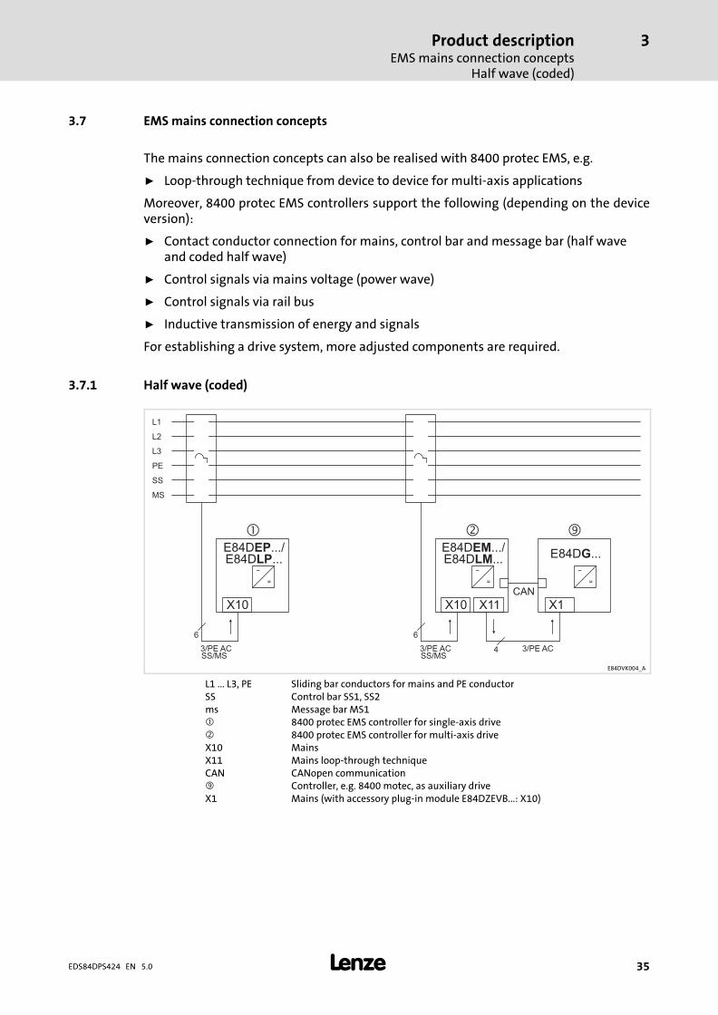
3.7 EMS mains connection concepts
The mains connection concepts can also be realised with 8400 protec EMS, e.g.
ƒ Loop−through technique from device to device for multi−axis applications
Moreover, 8400 protec EMS controllers support the following (depending on the deviceversion):
ƒ Contact conductor connection for mains, control bar and message bar (half waveand coded half wave)
ƒ Control signals via mains voltage (power wave)
ƒ Control signals via rail bus
ƒ Inductive transmission of energy and signals
For establishing a drive system, more adjusted components are required.
3.7.1 Half wave (coded)
X10 X1
3/PE AC 3/PE AC
~
=
~
=
� �
X10
�
3/PE AC
~
=
E84D ...GE84D .../EP E84D .../EM
L1
L2
L3
PE
MS
SS
SS/MS SS/MS
X11
4
CAN
E84D ...LP E84D ...LM
66
E84DVK004_A
L1 ... L3, PE Sliding bar conductors for mains and PE conductorSS Control bar SS1, SS2ms Message bar MS1� 8400 protec EMS controller for single−axis drive� 8400 protec EMS controller for multi−axis driveX10 MainsX11 Mains loop−through techniqueCAN CANopen communication Controller, e.g. 8400 motec, as auxiliary driveX1 Mains (with accessory plug−in module E84DZEVB...: X10)
Product descriptionEMS mains connection conceptsPower wave
3
� 36 EDS84DPS424 EN 5.0
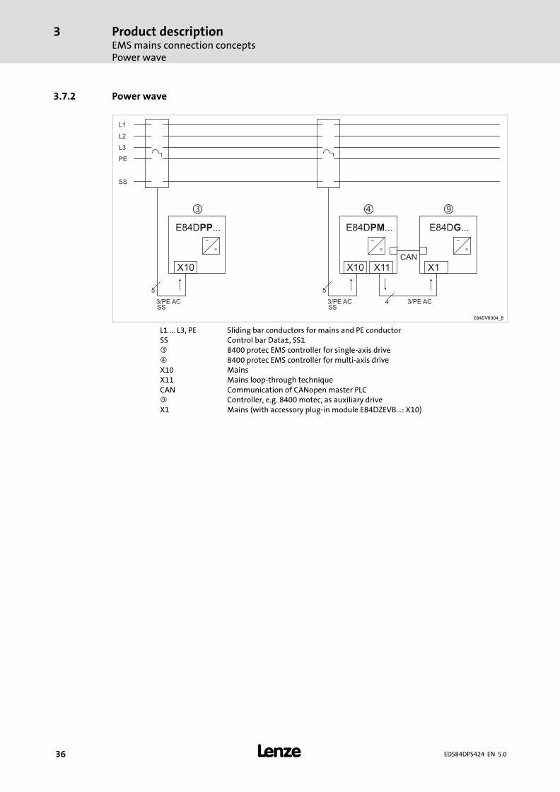
3.7.2 Power wave
~
=
X10
�
3/PE AC
E84D ...PP
X10 X1X11
� �
43/PE AC 3/PE AC
~
=
~
=
E84D ...PM E84D ...G
L1
L2
L3
PE
SS
SS SS
CAN
55
E84DVK004_B
L1 ... L3, PE Sliding bar conductors for mains and PE conductorSS Control bar Data±, SS1� 8400 protec EMS controller for single−axis drive� 8400 protec EMS controller for multi−axis driveX10 MainsX11 Mains loop−through techniqueCAN Communication of CANopen master PLC Controller, e.g. 8400 motec, as auxiliary driveX1 Mains (with accessory plug−in module E84DZEVB...: X10)
Product descriptionEMS mains connection concepts
DECA bus
3
� 37EDS84DPS424 EN 5.0
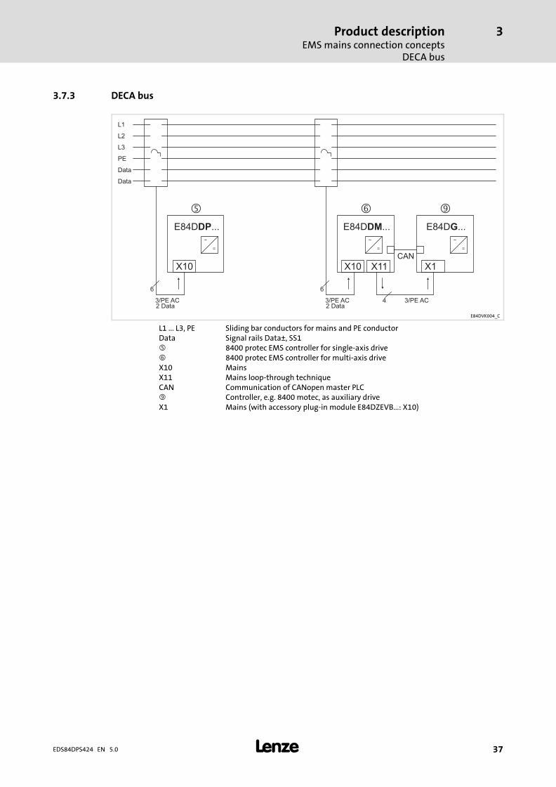
3.7.3 DECA bus
Data
~
=
X10
�
3/PE AC
E84D ...DP
X10 X1X11
� �
43/PE AC 3/PE AC
~
=
~
=
E84D ...DM E84D ...G
L1
L2
L3
PE
Data
2 Data 2 Data
CAN
66
E84DVK004_C
L1 ... L3, PE Sliding bar conductors for mains and PE conductorData Signal rails Data±, SS1 8400 protec EMS controller for single−axis drive� 8400 protec EMS controller for multi−axis driveX10 MainsX11 Mains loop−through techniqueCAN Communication of CANopen master PLC Controller, e.g. 8400 motec, as auxiliary driveX1 Mains (with accessory plug−in module E84DZEVB...: X10)
Product descriptionEMS mains connection conceptsInductive
3
� 38 EDS84DPS424 EN 5.0
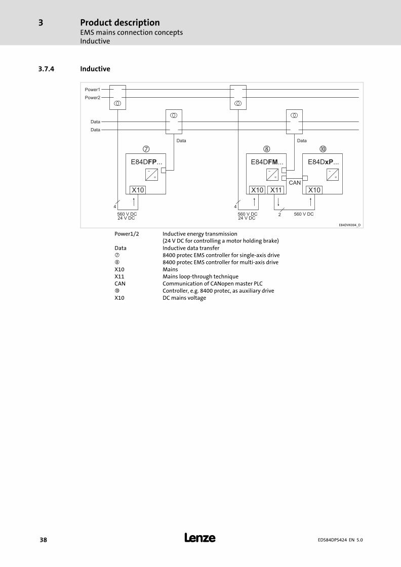
3.7.4 Inductive
X10
560 V DC 560 V DC 560 V DC
E84D ...FP
X10 X10X11
�
2
~
=
~
=
~
=
E84D ...FM E84D ...xP
Power1
Power2
Data
Data
24 V DC 24 V DC
CAN
44
Data Data
E84DVK004_D
Power1/2 Inductive energy transmission(24 V DC for controlling a motor holding brake)
Data Inductive data transfer� 8400 protec EMS controller for single−axis drive 8400 protec EMS controller for multi−axis driveX10 MainsX11 Mains loop−through techniqueCAN Communication of CANopen master PLC� Controller, e.g. 8400 protec, as auxiliary driveX10 DC mains voltage
Technical dataGeneral data and operating conditions
4
� 39EDS84DPS424 EN 5.0
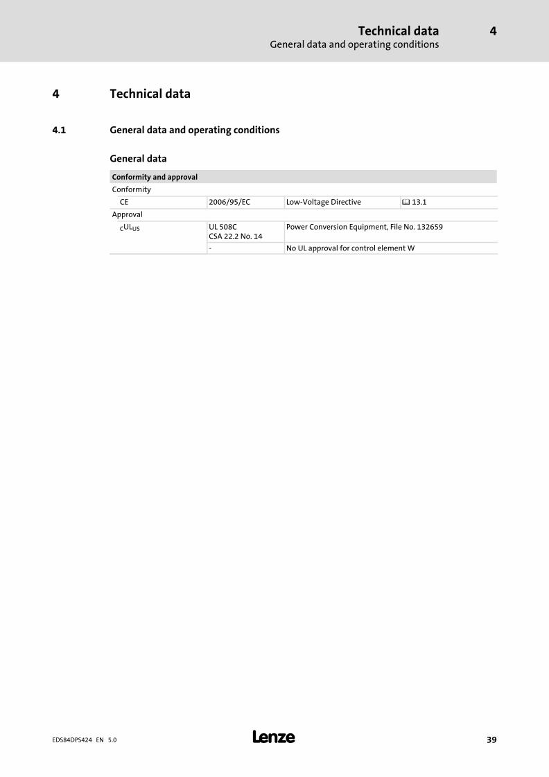
4 Technical data
4.1 General data and operating conditions
General data
Conformity and approval
Conformity
CE 2006/95/EC Low−Voltage Directive � 13.1
Approval
CULUS UL 508CCSA 22.2 No. 14
Power Conversion Equipment, File No. 132659
− No UL approval for control element W
Technical dataGeneral data and operating conditions
4
� 40 EDS84DPS424 EN 5.0
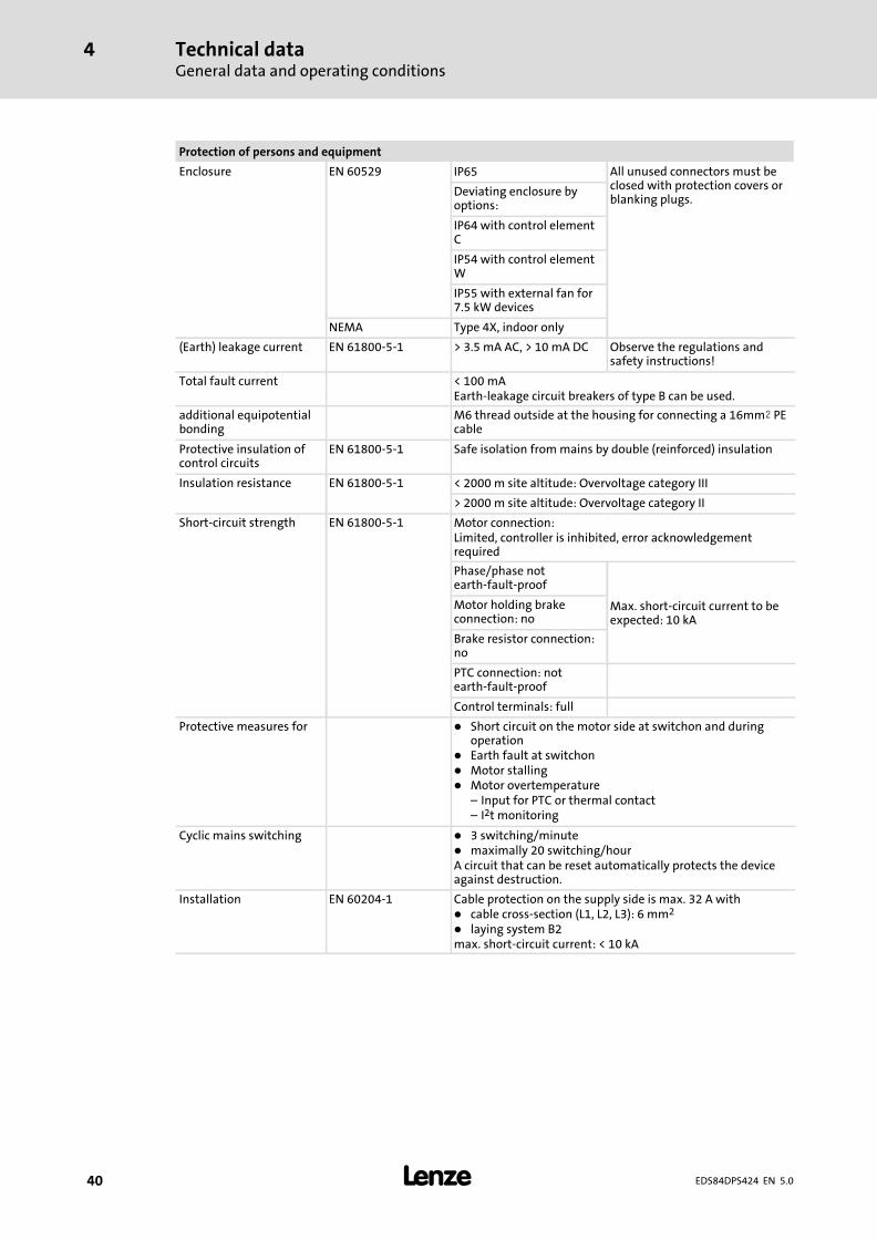
Protection of persons and equipment
Enclosure EN 60529 IP65 All unused connectors must beclosed with protection covers orblanking plugs.
Deviating enclosure byoptions:
IP64 with control elementC
IP54 with control elementW
IP55 with external fan for7.5 kW devices
NEMA Type 4X, indoor only
(Earth) leakage current EN 61800−5−1 > 3.5 mA AC, > 10 mA DC Observe the regulations andsafety instructions!
Total fault current < 100 mAEarth−leakage circuit breakers of type B can be used.
additional equipotentialbonding
M6 thread outside at the housing for connecting a 16mm� PEcable
Protective insulation ofcontrol circuits
EN 61800−5−1 Safe isolation from mains by double (reinforced) insulation
Insulation resistance EN 61800−5−1 < 2000 m site altitude: Overvoltage category III
> 2000 m site altitude: Overvoltage category II
Short−circuit strength EN 61800−5−1 Motor connection:Limited, controller is inhibited, error acknowledgementrequired
Phase/phase notearth−fault−proof
Max. short−circuit current to beexpected: 10 kA
Motor holding brakeconnection: no
Brake resistor connection:no
PTC connection: notearth−fault−proof
Control terminals: full
Protective measures for � Short circuit on the motor side at switchon and duringoperation
� Earth fault at switchon� Motor stalling� Motor overtemperature
– Input for PTC or thermal contact– I2t monitoring
Cyclic mains switching � 3 switching/minute� maximally 20 switching/hourA circuit that can be reset automatically protects the deviceagainst destruction.
Installation EN 60204−1 Cable protection on the supply side is max. 32 A with� cable cross−section (L1, L2, L3): 6 mm2
� laying system B2max. short−circuit current: < 10 kA
Technical dataGeneral data and operating conditions
4
� 41EDS84DPS424 EN 5.0
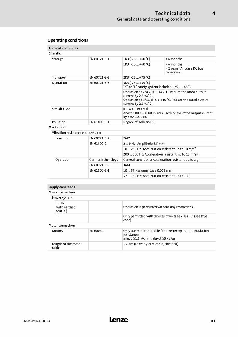
Operating conditions
Ambient conditions
Climatic
Storage EN 60721−3−1 1K3 (−25 ... +60 °C) < 6 months
1K3 (−25 ... +60 °C) > 6 months> 2 years: Anodise DC buscapacitors
Transport EN 60721−3−2 2K3 (−25 ... +75 °C)
Operation EN 60721−3−3 3K3 (−25 ... +55 °C)"K" or "L" safety system included: −25 ... +45 °C
Operation at 2/4 kHz: > +45 °C: Reduce the rated outputcurrent by 2.5 %/°C.Operation at 8/16 kHz: > +40 °C: Reduce the rated outputcurrent by 2.5 %/°C.
Site altitude 0 ... 4000 m amslAbove 1000 ... 4000 m amsl: Reduce the rated output currentby 5 %/ 1000 m.
Pollution EN 61800−5−1 Degree of pollution 2
Mechanical
Vibration resistance (9.81 m/s2 = 1 g)
Transport EN 60721−3−2 2M2
EN 61800−2 2 ... 9 Hz: Amplitude 3.5 mm
10 ... 200 Hz: Acceleration resistant up to 10 m/s2
200 ... 500 Hz: Acceleration resistant up to 15 m/s2
Operation Germanischer Lloyd General conditions: Acceleration resistant up to 2 g
EN 60721−3−3 3M4
EN 61800−5−1 10 ... 57 Hz: Amplitude 0.075 mm
57 ... 150 Hz: Acceleration resistant up to 1 g
Supply conditions
Mains connection
Power system
TT, TN(with earthedneutral)
Operation is permitted without any restrictions.
IT Only permitted with devices of voltage class "E" (see typecode).
Motor connection
Motors EN 60034 Only use motors suitable for inverter operation. Insulationresistance: min. û �1.5 kV, min. du/dt �5 kV/�s
Length of the motorcable
< 20 m (Lenze system cable, shielded)
Technical dataGeneral data and operating conditions
4
� 42 EDS84DPS424 EN 5.0
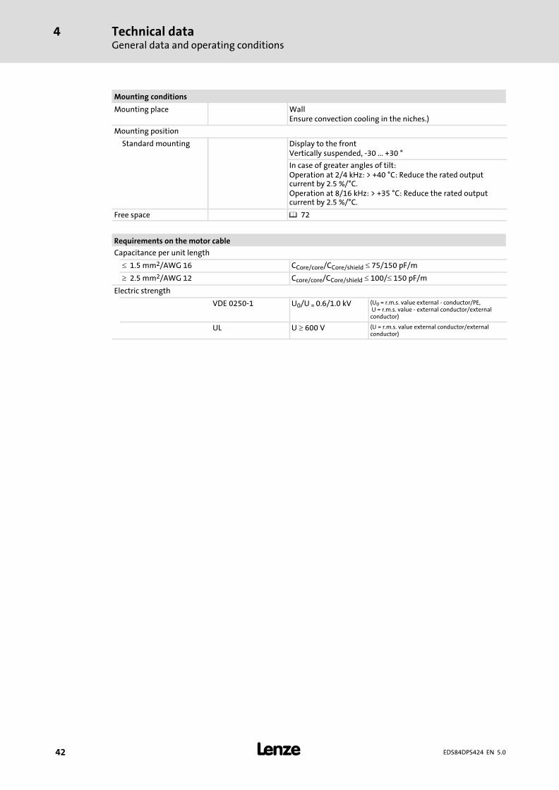
Mounting conditions
Mounting place WallEnsure convection cooling in the niches.)
Mounting position
Standard mounting Display to the frontVertically suspended, −30 ... +30 °
In case of greater angles of tilt:Operation at 2/4 kHz: > +40 °C: Reduce the rated outputcurrent by 2.5 %/°C.Operation at 8/16 kHz: > +35 °C: Reduce the rated outputcurrent by 2.5 %/°C.
Free space � 72
Requirements on the motor cable
Capacitance per unit length
� 1.5 mm2/AWG 16 CCore/core/CCore/shield � 75/150 pF/m
� 2.5 mm2/AWG 12 Ccore/core/CCore/shield � 100/� 150 pF/m
Electric strength
VDE 0250−1 U0/U = 0.6/1.0 kV (U0 = r.m.s. value external − conductor/PE, U = r.m.s. value − external conductor/externalconductor)
UL U � 600 V (U = r.m.s. value external conductor/externalconductor)
Technical dataGeneral data and operating conditions
4
� 43EDS84DPS424 EN 5.0
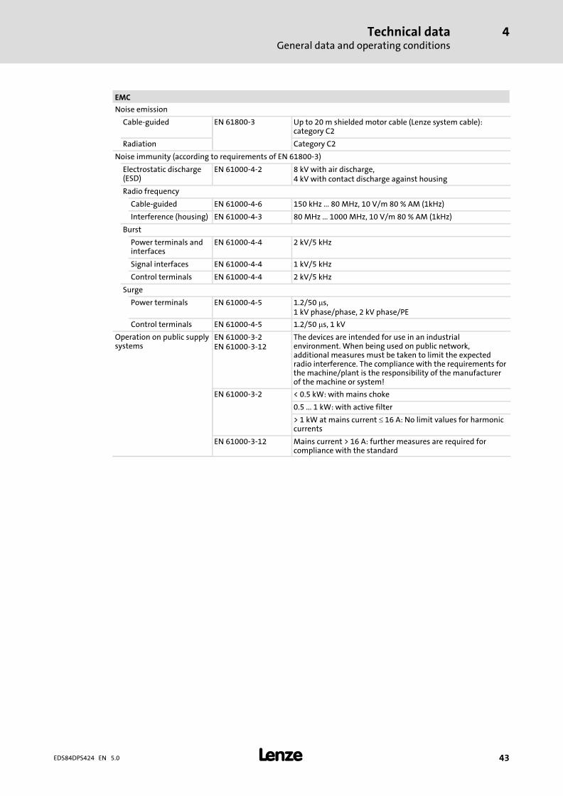
EMC
Noise emission
Cable−guided EN 61800−3 Up to 20 m shielded motor cable (Lenze system cable):category C2
Radiation Category C2
Noise immunity (according to requirements of EN 61800−3)
Electrostatic discharge(ESD)
EN 61000−4−2 8 kV with air discharge,4 kV with contact discharge against housing
Radio frequency
Cable−guided EN 61000−4−6 150 kHz ... 80 MHz, 10 V/m 80 % AM (1kHz)
Interference (housing) EN 61000−4−3 80 MHz ... 1000 MHz, 10 V/m 80 % AM (1kHz)
Burst
Power terminals andinterfaces
EN 61000−4−4 2 kV/5 kHz
Signal interfaces EN 61000−4−4 1 kV/5 kHz
Control terminals EN 61000−4−4 2 kV/5 kHz
Surge
Power terminals EN 61000−4−5 1.2/50 �s,1 kV phase/phase, 2 kV phase/PE
Control terminals EN 61000−4−5 1.2/50 �s, 1 kV
Operation on public supplysystems
EN 61000−3−2EN 61000−3−12
The devices are intended for use in an industrialenvironment. When being used on public network,additional measures must be taken to limit the expectedradio interference. The compliance with the requirements forthe machine/plant is the responsibility of the manufacturerof the machine or system!
EN 61000−3−2 < 0.5 kW: with mains choke
0.5 ... 1 kW: with active filter
> 1 kW at mains current � 16 A: No limit values for harmoniccurrents
EN 61000−3−12 Mains current > 16 A: further measures are required forcompliance with the standard
Technical dataGeneral data and operating conditions
4
� 44 EDS84DPS424 EN 5.0
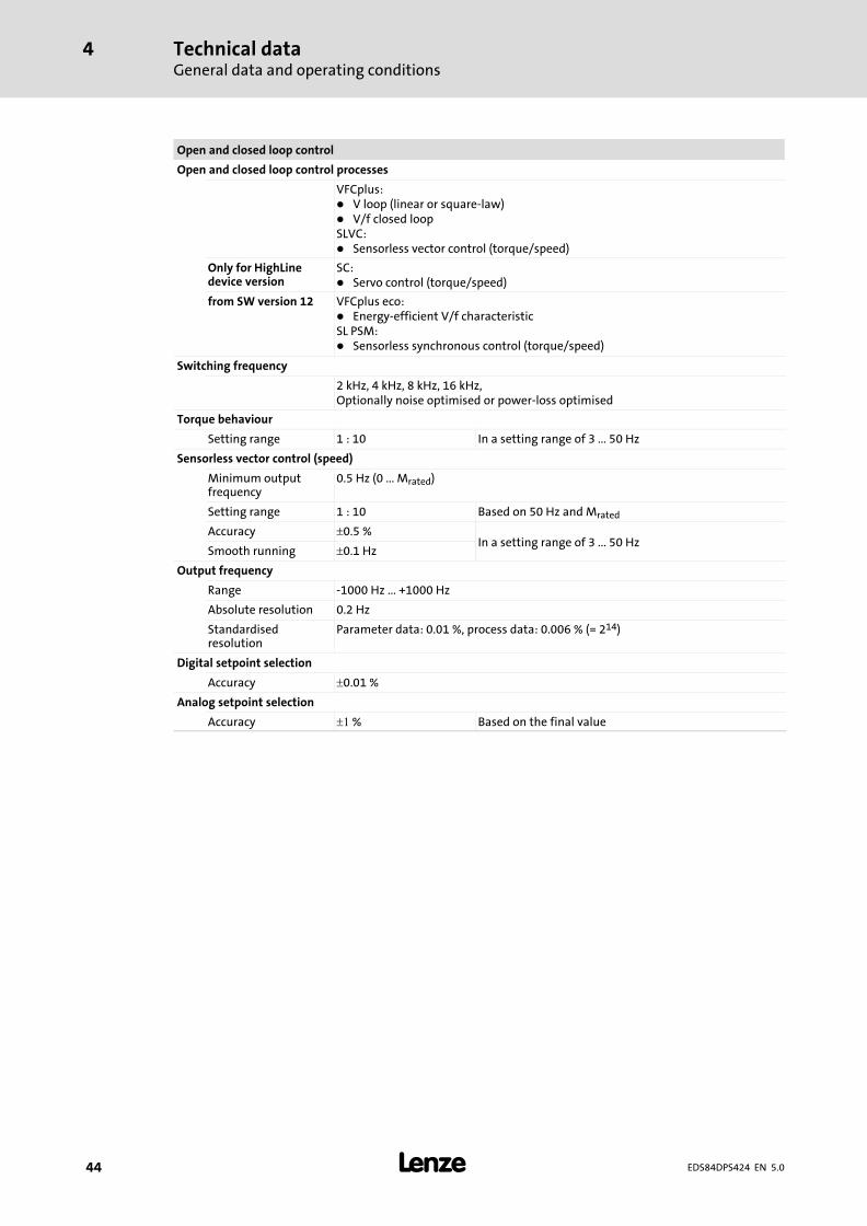
Open and closed loop control
Open and closed loop control processes
VFCplus:� V loop (linear or square−law)� V/f closed loopSLVC:� Sensorless vector control (torque/speed)
Only for HighLinedevice version
SC:� Servo control (torque/speed)
from SW version 12 VFCplus eco:� Energy−efficient V/f characteristicSL PSM:� Sensorless synchronous control (torque/speed)
Switching frequency
2 kHz, 4 kHz, 8 kHz, 16 kHz,Optionally noise optimised or power−loss optimised
Torque behaviour
Setting range 1 : 10 In a setting range of 3 ... 50 Hz
Sensorless vector control (speed)
Minimum outputfrequency
0.5 Hz (0 ... Mrated)
Setting range 1 : 10 Based on 50 Hz and Mrated
Accuracy �0.5 %In a setting range of 3 ... 50 Hz
Smooth running �0.1 Hz
Output frequency
Range −1000 Hz ... +1000 Hz
Absolute resolution 0.2 Hz
Standardisedresolution
Parameter data: 0.01 %, process data: 0.006 % (= 214)
Digital setpoint selection
Accuracy �0.01 %
Analog setpoint selection
Accuracy �� % Based on the final value
Technical dataGeneral data and operating conditions
4
� 45EDS84DPS424 EN 5.0
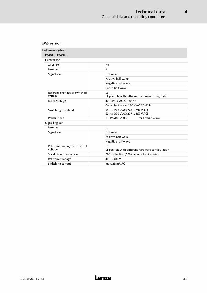
EMS version
Half−wave system
E84DE..., E84DL...
Control bar
Z system No
Number 2
Signal level Full wave
Positive half wave
Negative half wave
Coded half wave
Reference voltage or switchedvoltage
L3L1 possible with different hardware configuration
Rated voltage 400−480 V AC, 50−60 Hz
Coded half wave: 230 V AC, 50−60 Hz
Switching threshold 50 Hz: 270 V AC (243 ... 297 V AC)60 Hz: 330 V AC (297 ... 363 V AC)
Power input 1.5 W (400 V AC) for 1 x half wave
Signalling bar
Number 1
Signal level Full wave
Positive half wave
Negative half wave
Reference voltage or switchedvoltage
L3L1 possible with different hardware configuration
Short circuit protection PTC protection (500 � connected in series)
Reference voltage 400 ... 480 V
Switching current max. 28 mA AC
Technical dataRated dataOverview
4
� 46 EDS84DPS424 EN 5.0
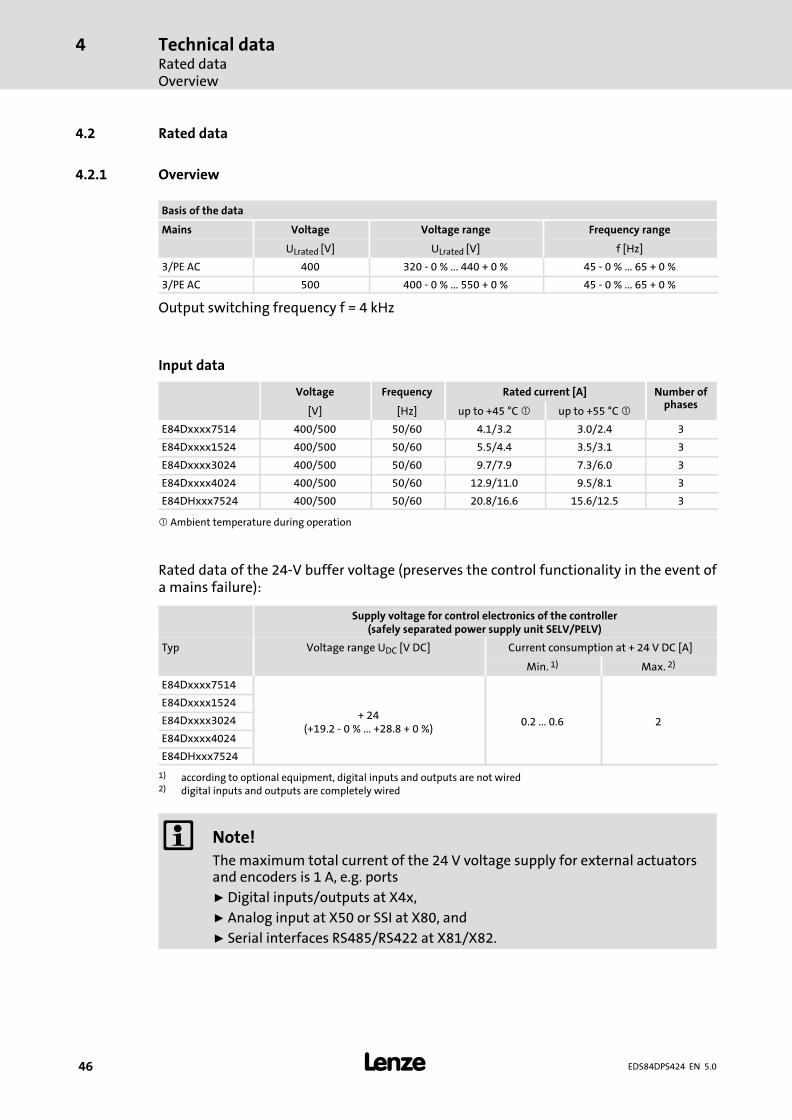
4.2 Rated data
4.2.1 Overview
Basis of the data
Mains Voltage Voltage range Frequency range
ULrated [V] ULrated [V] f [Hz]
3/PE AC 400 320 − 0 % ... 440 + 0 % 45 − 0 % ... 65 + 0 %
3/PE AC 500 400 − 0 % ... 550 + 0 % 45 − 0 % ... 65 + 0 %
Output switching frequency f = 4 kHz
Input data
Voltage Frequency Rated current [A] Number ofphases
[V] [Hz] up to +45 °C � up to +55 °C �
E84Dxxxx7514 400/500 50/60 4.1/3.2 3.0/2.4 3
E84Dxxxx1524 400/500 50/60 5.5/4.4 3.5/3.1 3
E84Dxxxx3024 400/500 50/60 9.7/7.9 7.3/6.0 3
E84Dxxxx4024 400/500 50/60 12.9/11.0 9.5/8.1 3
E84DHxxx7524 400/500 50/60 20.8/16.6 15.6/12.5 3
� Ambient temperature during operation
Rated data of the 24−V buffer voltage (preserves the control functionality in the event ofa mains failure):
Supply voltage for control electronics of the controller(safely separated power supply unit SELV/PELV)
Typ Voltage range UDC [V DC] Current consumption at + 24 V DC [A]
Min. 1) Max. 2)
E84Dxxxx7514
+ 24(+19.2 − 0 % ... +28.8 + 0 %)
0.2 ... 0.6 2
E84Dxxxx1524
E84Dxxxx3024
E84Dxxxx4024
E84DHxxx7524
1) according to optional equipment, digital inputs and outputs are not wired2) digital inputs and outputs are completely wired
� Note!
The maximum total current of the 24 V voltage supply for external actuatorsand encoders is 1 A, e.g. ports
ƒ Digital inputs/outputs at X4x,
ƒ Analog input at X50 or SSI at X80, and
ƒ Serial interfaces RS485/RS422 at X81/X82.
Technical dataRated data
Overview
4
� 47EDS84DPS424 EN 5.0
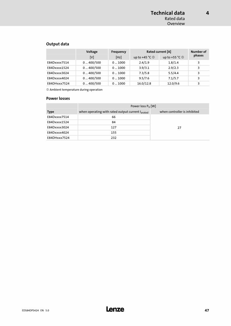
Output data
Voltage Frequency Rated current [A] Number ofphases
[V] [Hz] up to +45 °C � up to +55 °C �
E84Dxxxx7514 0 ... 400/500 0 ... 1000 2.4/1.9 1.8/1.4 3
E84Dxxxx1524 0 ... 400/500 0 ... 1000 3.9/3.1 2.9/2.3 3
E84Dxxxx3024 0 ... 400/500 0 ... 1000 7.3/5.8 5.5/4.4 3
E84Dxxxx4024 0 ... 400/500 0 ... 1000 9.5/7.6 7.1/5.7 3
E84DHxxx7524 0 ... 400/500 0 ... 1000 16.0/12.8 12.0/9.6 3
� Ambient temperature during operation
Power losses
Power loss PV [W]
Type when operating with rated output current Iarated when controller is inhibited
E84Dxxxx7514 66
27
E84Dxxxx1524 84
E84Dxxxx3024 127
E84Dxxxx4024 155
E84DHxxx7524 232
Technical dataRated dataOperation at rated mains voltage 400 V
4
� 48 EDS84DPS424 EN 5.0
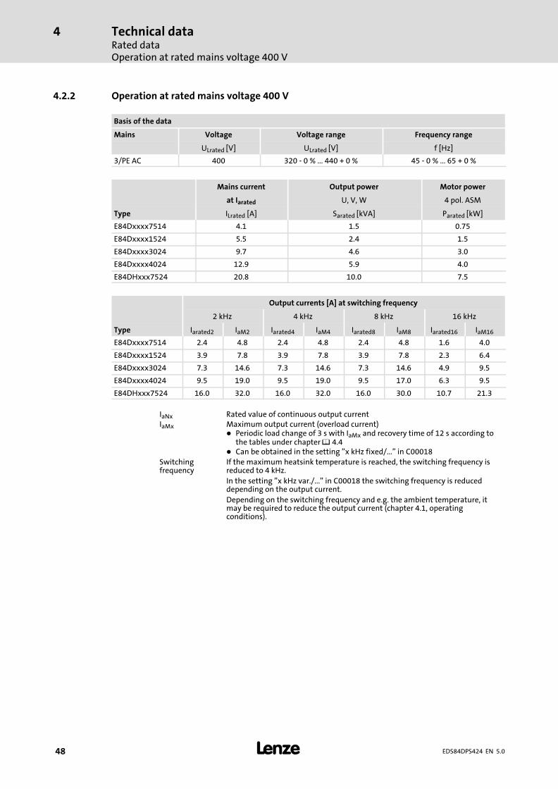
4.2.2 Operation at rated mains voltage 400 V
Basis of the data
Mains Voltage Voltage range Frequency range
ULrated [V] ULrated [V] f [Hz]
3/PE AC 400 320 − 0 % ... 440 + 0 % 45 − 0 % ... 65 + 0 %
Mains current Output power Motor power
at Iarated U, V, W 4 pol. ASM
Type ILrated [A] Sarated [kVA] Parated [kW]
E84Dxxxx7514 4.1 1.5 0.75
E84Dxxxx1524 5.5 2.4 1.5
E84Dxxxx3024 9.7 4.6 3.0
E84Dxxxx4024 12.9 5.9 4.0
E84DHxxx7524 20.8 10.0 7.5
Output currents [A] at switching frequency
2 kHz 4 kHz 8 kHz 16 kHz
Type Iarated2 IaM2 Iarated4 IaM4 Iarated8 IaM8 Iarated16 IaM16
E84Dxxxx7514 2.4 4.8 2.4 4.8 2.4 4.8 1.6 4.0
E84Dxxxx1524 3.9 7.8 3.9 7.8 3.9 7.8 2.3 6.4
E84Dxxxx3024 7.3 14.6 7.3 14.6 7.3 14.6 4.9 9.5
E84Dxxxx4024 9.5 19.0 9.5 19.0 9.5 17.0 6.3 9.5
E84DHxxx7524 16.0 32.0 16.0 32.0 16.0 30.0 10.7 21.3
IaNx Rated value of continuous output currentIaMx Maximum output current (overload current)
� Periodic load change of 3 s with IaMx and recovery time of 12 s according tothe tables under chapter � 4.4
� Can be obtained in the setting "x kHz fixed/..." in C00018Switchingfrequency
If the maximum heatsink temperature is reached, the switching frequency isreduced to 4 kHz.
In the setting "x kHz var./..." in C00018 the switching frequency is reduceddepending on the output current.
Depending on the switching frequency and e.g. the ambient temperature, itmay be required to reduce the output current (chapter 4.1, operatingconditions).
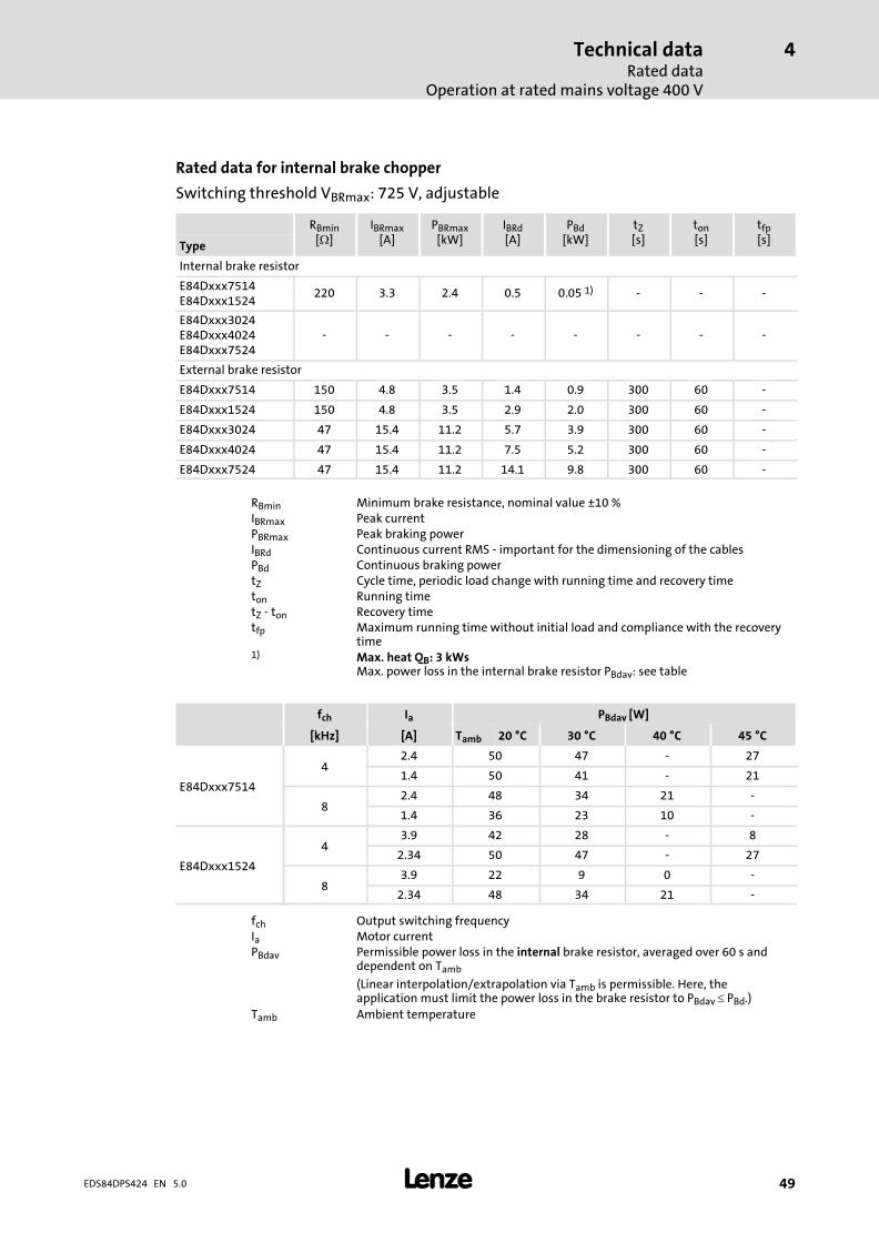
Technical dataRated data
Operation at rated mains voltage 400 V
4
� 49EDS84DPS424 EN 5.0
Rated data for internal brake chopper
Switching threshold VBRmax: 725 V, adjustable
RBmin[�]
IBRmax[A]
PBRmax[kW]
IBRd[A]
PBd[kW]
tZ[s]
ton[s]
tfp[s]Type
Internal brake resistor
E84Dxxx7514E84Dxxx1524
220 3.3 2.4 0.5 0.05 1) − − −
E84Dxxx3024E84Dxxx4024E84Dxxx7524
− − − − − − − −
External brake resistor
E84Dxxx7514 150 4.8 3.5 1.4 0.9 300 60 −
E84Dxxx1524 150 4.8 3.5 2.9 2.0 300 60 −
E84Dxxx3024 47 15.4 11.2 5.7 3.9 300 60 −
E84Dxxx4024 47 15.4 11.2 7.5 5.2 300 60 −
E84Dxxx7524 47 15.4 11.2 14.1 9.8 300 60 −
RBmin Minimum brake resistance, nominal value ±10 %IBRmax Peak currentPBRmax Peak braking powerIBRd Continuous current RMS − important for the dimensioning of the cablesPBd Continuous braking powertZ Cycle time, periodic load change with running time and recovery timeton Running timetZ − ton Recovery timetfp Maximum running time without initial load and compliance with the recovery
time1) Max. heat QB: 3 kWs
Max. power loss in the internal brake resistor PBdav: see table
fch Ia PBdav [W]
[kHz] [A] Tamb 20 °C 30 °C 40 °C 45 °C
E84Dxxx7514
42.4 50 47 − 27
1.4 50 41 − 21
82.4 48 34 21 −
1.4 36 23 10 −
E84Dxxx1524
43.9 42 28 − 8
2.34 50 47 − 27
83.9 22 9 0 −
2.34 48 34 21 −
fch Output switching frequencyIa Motor currentPBdav Permissible power loss in the internal brake resistor, averaged over 60 s and
dependent on Tamb
(Linear interpolation/extrapolation via Tamb is permissible. Here, theapplication must limit the power loss in the brake resistor to PBdav � PBd.)
Tamb Ambient temperature
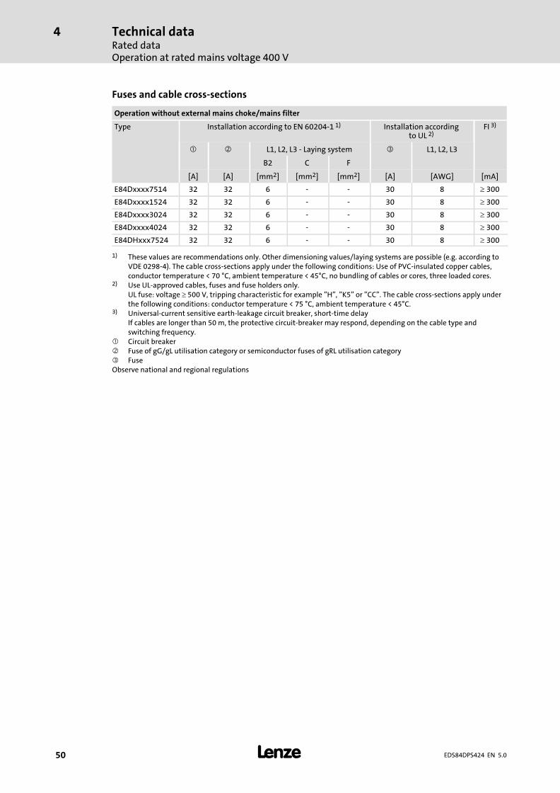
Technical dataRated dataOperation at rated mains voltage 400 V
4
� 50 EDS84DPS424 EN 5.0
Fuses and cable cross−sections
Operation without external mains choke/mains filter
Type Installation according to EN 60204−1 1) Installation accordingto UL 2)
FI 3)
� � L1, L2, L3 − Laying system � L1, L2, L3
B2 C F
[A] [A] [mm2] [mm2] [mm2] [A] [AWG] [mA]
E84Dxxxx7514 32 32 6 − − 30 8 � 300
E84Dxxxx1524 32 32 6 − − 30 8 � 300
E84Dxxxx3024 32 32 6 − − 30 8 � 300
E84Dxxxx4024 32 32 6 − − 30 8 � 300
E84DHxxx7524 32 32 6 − − 30 8 � 300
1) These values are recommendations only. Other dimensioning values/laying systems are possible (e.g. according toVDE 0298−4). The cable cross−sections apply under the following conditions: Use of PVC−insulated copper cables,conductor temperature < 70 °C, ambient temperature < 45°C, no bundling of cables or cores, three loaded cores.
2) Use UL−approved cables, fuses and fuse holders only.UL fuse: voltage � 500 V, tripping characteristic for example "H", "K5" or "CC". The cable cross−sections apply underthe following conditions: conductor temperature < 75 °C, ambient temperature < 45°C.
3) Universal−current sensitive earth−leakage circuit breaker, short−time delayIf cables are longer than 50 m, the protective circuit−breaker may respond, depending on the cable type andswitching frequency.
� Circuit breaker� Fuse of gG/gL utilisation category or semiconductor fuses of gRL utilisation category� FuseObserve national and regional regulations
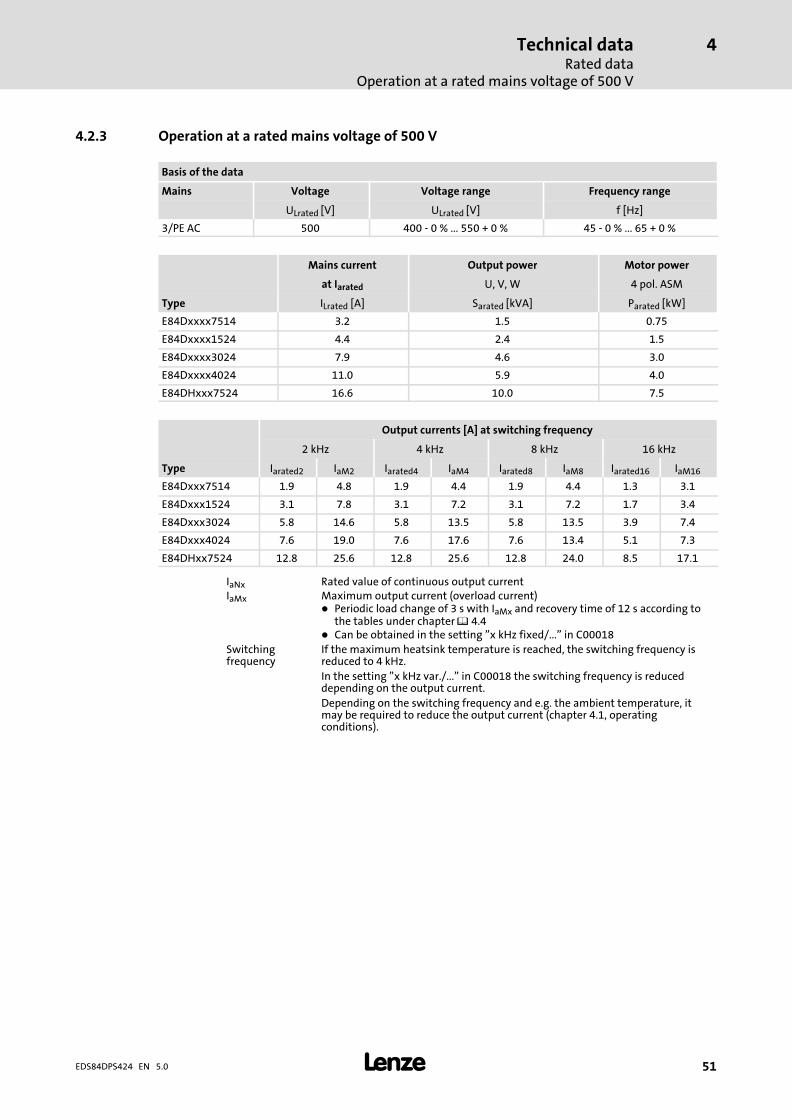
Technical dataRated data
Operation at a rated mains voltage of 500 V
4
� 51EDS84DPS424 EN 5.0
4.2.3 Operation at a rated mains voltage of 500 V
Basis of the data
Mains Voltage Voltage range Frequency range
ULrated [V] ULrated [V] f [Hz]
3/PE AC 500 400 − 0 % ... 550 + 0 % 45 − 0 % ... 65 + 0 %
Mains current Output power Motor power
at Iarated U, V, W 4 pol. ASM
Type ILrated [A] Sarated [kVA] Parated [kW]
E84Dxxxx7514 3.2 1.5 0.75
E84Dxxxx1524 4.4 2.4 1.5
E84Dxxxx3024 7.9 4.6 3.0
E84Dxxxx4024 11.0 5.9 4.0
E84DHxxx7524 16.6 10.0 7.5
Output currents [A] at switching frequency
2 kHz 4 kHz 8 kHz 16 kHz
Type Iarated2 IaM2 Iarated4 IaM4 Iarated8 IaM8 Iarated16 IaM16
E84Dxxx7514 1.9 4.8 1.9 4.4 1.9 4.4 1.3 3.1
E84Dxxx1524 3.1 7.8 3.1 7.2 3.1 7.2 1.7 3.4
E84Dxxx3024 5.8 14.6 5.8 13.5 5.8 13.5 3.9 7.4
E84Dxxx4024 7.6 19.0 7.6 17.6 7.6 13.4 5.1 7.3
E84DHxx7524 12.8 25.6 12.8 25.6 12.8 24.0 8.5 17.1
IaNx Rated value of continuous output currentIaMx Maximum output current (overload current)
� Periodic load change of 3 s with IaMx and recovery time of 12 s according tothe tables under chapter � 4.4
� Can be obtained in the setting "x kHz fixed/..." in C00018Switchingfrequency
If the maximum heatsink temperature is reached, the switching frequency isreduced to 4 kHz.
In the setting "x kHz var./..." in C00018 the switching frequency is reduceddepending on the output current.
Depending on the switching frequency and e.g. the ambient temperature, itmay be required to reduce the output current (chapter 4.1, operatingconditions).
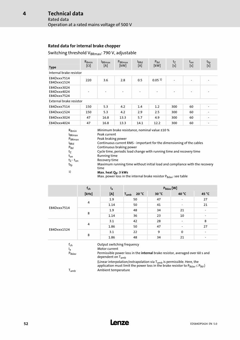
Technical dataRated dataOperation at a rated mains voltage of 500 V
4
� 52 EDS84DPS424 EN 5.0
Rated data for internal brake chopper
Switching threshold VBRmax: 790 V, adjustable
RBmin[�]
IBRmax[A]
PBRmax[kW]
IBRd[A]
PBd[kW]
tZ[s]
ton[s]
tfp[s]Type
Internal brake resistor
E84Dxxx7514E84Dxxx1524
220 3.6 2.8 0.5 0.05 1) − − −
E84Dxxx3024E84Dxxx4024E84Dxxx7524
− − − − − − − −
External brake resistor
E84Dxxx7514 150 5.3 4.2 1.4 1.2 300 60 −
E84Dxxx1524 150 5.3 4.2 2.9 2.5 300 60 −
E84Dxxx3024 47 16.8 13.3 5.7 4.9 300 60 −
E84Dxxx4024 47 16.8 13.3 14.1 12.2 300 60 −
RBmin Minimum brake resistance, nominal value ±10 %IBRmax Peak currentPBRmax Peak braking powerIBRd Continuous current RMS − important for the dimensioning of the cablesPBd Continuous braking powertZ Cycle time, periodic load change with running time and recovery timeton Running timetZ − ton Recovery timetfp Maximum running time without initial load and compliance with the recovery
time1) Max. heat QB: 3 kWs
Max. power loss in the internal brake resistor PBdav: see table
fch Ia PBdav [W]
[kHz] [A] Tamb 20 °C 30 °C 40 °C 45 °C
E84Dxxx7514
41.9 50 47 − 27
1.14 50 41 − 21
81.9 48 34 21 −
1.14 36 23 10 −
E84Dxxx1524
43.1 42 28 − 8
1.86 50 47 − 27
83.1 22 9 0 −
1.86 48 34 21 −
fch Output switching frequencyIa Motor currentPBdav Permissible power loss in the internal brake resistor, averaged over 60 s and
dependent on Tamb
(Linear interpolation/extrapolation via Tamb is permissible. Here, theapplication must limit the power loss in the brake resistor to PBdav � PBd.)
Tamb Ambient temperature
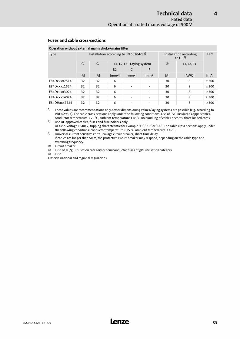
Technical dataRated data
Operation at a rated mains voltage of 500 V
4
� 53EDS84DPS424 EN 5.0
Fuses and cable cross−sections
Operation without external mains choke/mains filter
Type Installation according to EN 60204−1 1) Installation accordingto UL 2)
FI 3)
� � L1, L2, L3 − Laying system � L1, L2, L3
B2 C F
[A] [A] [mm2] [mm2] [mm2] [A] [AWG] [mA]
E84Dxxxx7514 32 32 6 − − 30 8 � 300
E84Dxxxx1524 32 32 6 − − 30 8 � 300
E84Dxxxx3024 32 32 6 − − 30 8 � 300
E84Dxxxx4024 32 32 6 − − 30 8 � 300
E84DHxxx7524 32 32 6 − − 30 8 � 300
1) These values are recommendations only. Other dimensioning values/laying systems are possible (e.g. according toVDE 0298−4). The cable cross−sections apply under the following conditions: Use of PVC−insulated copper cables,conductor temperature < 70 °C, ambient temperature < 45°C, no bundling of cables or cores, three loaded cores.
2) Use UL−approved cables, fuses and fuse holders only.UL fuse: voltage � 500 V, tripping characteristic for example "H", "K5" or "CC". The cable cross−sections apply underthe following conditions: conductor temperature < 75 °C, ambient temperature < 45°C.
3) Universal−current sensitive earth−leakage circuit breaker, short−time delayIf cables are longer than 50 m, the protective circuit−breaker may respond, depending on the cable type andswitching frequency.
� Circuit breaker� Fuse of gG/gL utilisation category or semiconductor fuses of gRL utilisation category� FuseObserve national and regional regulations
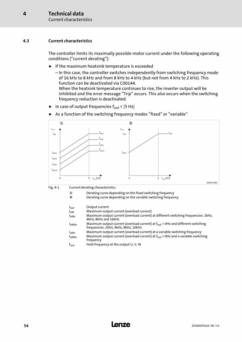
Technical dataCurrent characteristics
4
� 54 EDS84DPS424 EN 5.0
4.3 Current characteristics
The controller limits its maximally possible motor current under the following operatingconditions ("current derating"):
ƒ If the maximum heatsink temperature is exceeded
– In this case, the controller switches independently from switching frequency modeof 16 kHz to 8 kHz and from 8 kHz to 4 kHz (but not from 4 kHz to 2 kHz). Thisfunction can be deactivated via C00144.When the heatsink temperature continues to rise, the inverter output will beinhibited and the error message "Trip" occurs. This also occurs when the switchingfrequency reduction is deactivated.
ƒ In case of output frequencies fout < |5 Hz|
ƒ As a function of the switching frequency modes "fixed" or "variable"
0 05 5f [Hz]out f [Hz]out
� �
IOUT IOUT
IaMIaM
IaM02
IaM04
IaM08
IaM016
IaM0v
IaM2
IaM4
IaM8
IaM16
IaMv
8400GG084
Fig. 4−1 Current derating characteristics
� Derating curve depending on the fixed switching frequency Derating curve depending on the variable switching frequency
Iout Output currentIaM Maximum output current (overload current)IaMx Maximum output current (overload current) at different switching frequencies: 2kHz,
4kHz, 8kHz and 16kHz
IaM0x Maximum output current (overload current) at fout = 0Hz and different switchingfrequencies: 2kHz, 4kHz, 8kHz, 16kHz
IaMv Maximum output current (overload current) at a variable switching frequencyIaM0v Maximum output current (overload current) at fout = 0Hz and a variable switching
frequency
fout Field frequency at the output U, V, W
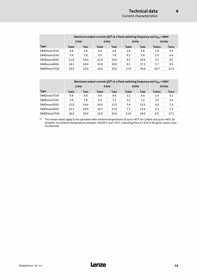
Technical dataCurrent characteristics
4
� 55EDS84DPS424 EN 5.0
Maximum output currents [A]1) at a fixed switching frequency and ULN = 400V
2 kHz 4 kHz 8 kHz 16 kHz
Type IaM02 IaM2 IaM04 IaM4 IaM08 IaM8 IaM016 IaM16
E84Dxxxx7514 4.8 4.8 4.8 4.8 2.8 4.8 1.8 4.0
E84Dxxxx1524 5.9 7.8 5.9 7.8 4.1 7.8 2.5 6.4
E84Dxxxx3024 11.0 14.6 11.0 14.6 9.5 14.6 5.5 9.5
E84Dxxxx4024 14.3 19.0 13.8 19.0 9.5 17.1 5.7 9.5
E84DHxxx7524 16.0 32.0 16.0 32.0 17.0 30.0 10.7 21.3
Maximum output currents [A]1) at a fixed switching frequency and ULN = 500V
2 kHz 4 kHz 8 kHz 16 kHz
Type IaM02 IaM2 IaM04 IaM4 IaM08 IaM8 IaM016 IaM16
E84Dxxxx7514 4.8 4.8 4.4 4.4 2.1 4.4 1.4 3.1
E84Dxxxx1524 5.9 7.8 5.9 7.2 3.2 7.2 1.9 3.4
E84Dxxxx3024 11.0 14.6 10.6 13.5 7.4 13.5 4.2 7.4
E84Dxxxx4024 14.3 19.0 10.7 17.6 7.3 13.4 4.3 7.3
E84DHxxx7524 16.0 25.6 12.8 25.6 13.6 24.0 8.5 17.1
1) The shown values apply to the operation with ambient temperatures of up to +45°C for 2/4kHz and up to +40°C for8/16kHz. For ambient temperatures between +40/45°C and +55°C, a derating from 2.5 %/K to the given values mustbe observed.
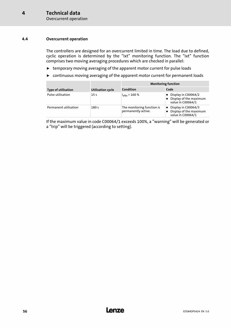
Technical dataOvercurrent operation
4
� 56 EDS84DPS424 EN 5.0
4.4 Overcurrent operation
The controllers are designed for an overcurrent limited in time. The load due to defined,cyclic operation is determined by the "Ixt" monitoring function. The "Ixt" functioncomprises two moving averaging procedures which are checked in parallel:
ƒ temporary moving averaging of the apparent motor current for pulse loads
ƒ continuous moving averaging of the apparent motor current for permanent loads
Type of utilisation Utilisation cycle
Monitoring function
Condition Code
Pulse utilisation 15 s IaNx > 160 % � Display in C00064/2� Display of the maximum
value in C00064/1
Permanent utilisation 180 s The monitoring function ispermanently active.
� Display in C00064/3� Display of the maximum
value in C00064/1
If the maximum value in code C00064/1 exceeds 100%, a "warning" will be generated ora "trip" will be triggered (according to setting).
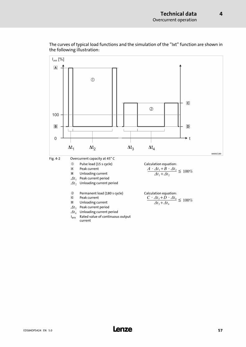
Technical dataOvercurrent operation
4
� 57EDS84DPS424 EN 5.0
The curves of typical load functions and the simulation of the "Ixt" function are shown inthe following illustration:
t0
100
�
�
�
I [%]aN8
�
Dt1
�
�
Dt2 Dt3 Dt48400IZ180
Fig. 4−2 Overcurrent capacity at 45° C
� Pulse load (15 s cycle) Calculation equation:
� Peak current A � �t1�B � �t2
�t1��t2� 100%
Unloading current
�t1 Peak current period
�t2 Unloading current period
� Permanent load (180 s cycle) Calculation equation:� Peak current C � �t3�D � �t4
�t3��t4� 100%
� Unloading current
�t3 Peak current period
�t4 Unloading current period
Iarx Rated value of continuous outputcurrent
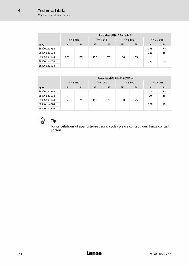
Technical dataOvercurrent operation
4
� 58 EDS84DPS424 EN 5.0
Type
Iamax/IaR8 [%] in 15−s cycle �
f = 2 kHz f = 4 kHz f = 8 kHz f = 16 kHz
� � � �
E84Dxxx7514
200 75 200 75 200 75
133 50
E84Dxxx1524 120 45
E84Dxxx3024
133 50E84Dxxx4024
E84Dxxx7524
Type
Iamax/IaR8 [%] in 180−s cycle �
f = 2 kHz f = 4 kHz f = 8 kHz f = 16 kHz
� � � � � � � �
E84Dxxx7514
150 75 150 75 150 75
100 50
E84Dxxx1524 90 45
E84Dxxx3024
100 50E84Dxxx4024
E84Dxxx7524
� Tip!
For calculations of application−specific cycles please contact your Lenze contactperson.
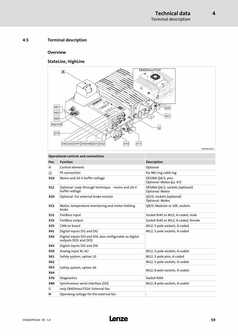
Technical dataTerminal description
4
� 59EDS84DPS424 EN 5.0
4.5 Terminal description
Overview
StateLine, HighLine
E84DWGA010
Operational controls and connections
Pos. Function Description
� Control element Optional
� PE connection for M6 ring cable lug
X10 Mains and 24−V buffer voltage DESINA Q4/2, pinsOptional: Molex (� 87)
X11 Optional: Loop−through technique − mains and 24−Vbuffer voltage
DESINA Q4/2, sockets (optional)Optional: Molex
X20 Optional: For external brake resistor Q5/0, sockets (optional)Optional: Molex
X21 Motor, temperature monitoring and motor holdingbrake
Q8/0, Modular or 10E, sockets
X31 Fieldbus input Socket RJ45 or M12, A−coded, male
X32 Fieldbus output Socket RJ45 or M12, A−coded, female
X35 CAN on board M12, 5−pole sockets, A−coded
X41 Digital inputs DI1 and DI2 M12, 5−pole sockets, A−coded
X42 Digital inputs DI3 and DI4, also configurable as digitaloutputs DO1 and DO2
X43 Digital inputs DI5 and DI6
X50 Analog input AI, AU M12, 5−pole sockets, A−coded
X61 Safety system, option 10 M12, 5−pole pins, A−coded
X62
Safety system, option 30
M12, 5−pole sockets, A−coded
X63M12, 8−pole sockets, A−coded
X64
X70 Diagnostics Socket RJ69
X80 Synchronous serial interface (SSI) M12, 8−pole sockets, A−coded
� only E84DHxxx7524: External fan
� Operating voltage for the external fan −
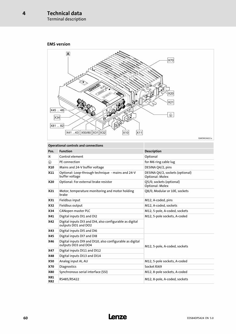
Technical dataTerminal description
4
� 60 EDS84DPS424 EN 5.0
EMS version
E84DWGA015 a
Operational controls and connections
Pos. Function Description
� Control element Optional
� PE connection for M6 ring cable lug
X10 Mains and 24−V buffer voltage DESINA Q4/2, pins
X11 Optional: Loop−through technique − mains and 24−Vbuffer voltage
DESINA Q4/2, sockets (optional)Optional: Molex
X20 Optional: For external brake resistor Q5/0, sockets (optional)Optional: Molex
X21 Motor, temperature monitoring and motor holdingbrake
Q8/0, Modular or 10E, sockets
X31 Fieldbus input M12, A−coded, pins
X32 Fieldbus output M12, A−coded, sockets
X34 CANopen master PLC M12, 5−pole, A−coded, sockets
X41 Digital inputs DI1 and DI2 M12, 5−pole sockets, A−coded
X42 Digital inputs DI3 and DI4, also configurable as digitaloutputs DO1 and DO2
X43 Digital inputs DI5 and DI6
X45 Digital inputs DI7 and DI8
M12, 5−pole, A−coded, sockets
X46 Digital inputs DI9 and DI10, also configurable as digitaloutputs DO3 and DO4
X47 Digital inputs DI11 and DI12
X48 Digital inputs DI13 and DI14
X50 Analog input AI, AU M12, 5−pole sockets, A−coded
X70 Diagnostics Socket RJ69
X80 Synchronous serial interface (SSI) M12, 8−pole sockets, A−coded
X81X82
RS485/RS422 M12, 8−pole, A−coded, sockets
Technical dataSupply concept of control voltage
Internal 24 V supply voltage
4
� 61EDS84DPS424 EN 5.0
4.6 Supply concept of control voltage
8400 protec controllers generate the 24 V supply voltage of the control electronics fromthe mains voltage by means of an integrated power supply unit (mains−operated supply).
An external 24 V buffer voltage from a safely separated power supply unit (SELV/PELV)must be connected in order to implement a self−contained supply of the controlelectronics.
The 24 V supply voltage is required for the control electronics and other components suchas fieldbus communication and/or drive−based safety.In addition, the supply voltage is available at the terminals, irrespective of the fact whetherit is fed internally or externally. Information on the supply voltage at the digital and analogterminals is provided under:
ƒ Digital inputs(� 64)
ƒ Digital outputs(� 65)
ƒ Analog inputs(� 66)
ƒ Synchronous serial interface (SSI) (� 66)
The supply voltage is preferentially used for:
ƒ Connecting potential−free contacts to digital inputs
ƒ Supplying external sensors
At an external 24 V supply voltage, the rated values may deviate according to the voltagesource.
4.6.1 Internal 24 V supply voltage
At an internal 24 V supply voltage, the maximally permissible total current of terminalsX4x, X50/X8x is 1 A.
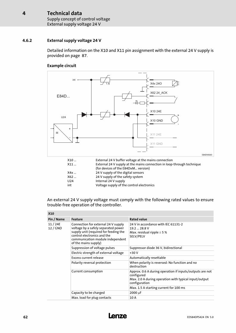
Technical dataSupply concept of control voltageExternal supply voltage 24 V
4
� 62 EDS84DPS424 EN 5.0
4.6.2 External supply voltage 24 V
Detailed information on the X10 and X11 pin assignment with the external 24 V supply isprovided on page 87.
Example circuit
U24
=+
-
X4x 24O
X11 GND
X10 GND
X11 24E
X10 24E
X62 24_ACK
int
+
-
1 A
E84D...
E84DVK003
X10 ... External 24 V buffer voltage at the mains connectionX11 ... External 24 V supply at the mains connection in loop−through technique
(for devices of the E84DxM... version)X4x ... 24 V supply of the digital sensorsX62 ... 24 V supply of the safety systemU24 Internal 24 V supplyint Voltage supply of the control electronics
An external 24 V supply voltage must comply with the following rated values to ensuretrouble−free operation of the controller.
X10
Pin / Name Feature Rated value
11 / 24E12 / GND
Connection for external 24 V supplyvoltage by a safely separated powersupply unit (required for feeding thecontrol electronics and thecommunication module independentof the mains supply)
24 V in accordance with IEC 61131−219.2 ... 28.8 VMax. residual ripple � 5 %SELV/PELV
Suppression of voltage pulses Suppressor diode 36 V, bidirectional
Electric strength of external voltage +30 V
Excess current release Automatically resettable
Polarity reversal protection When polarity is reversed: No function and nodestruction
Current consumption Approx. 0.6 A during operation if inputs/outputs are notconfiguredMax. 2.0 A during operation with typical input/outputconfiguration
Max. 1.5 A starting current for 100 ms
Capacity to be charged 2000 �F
Max. load for plug contacts 10 A
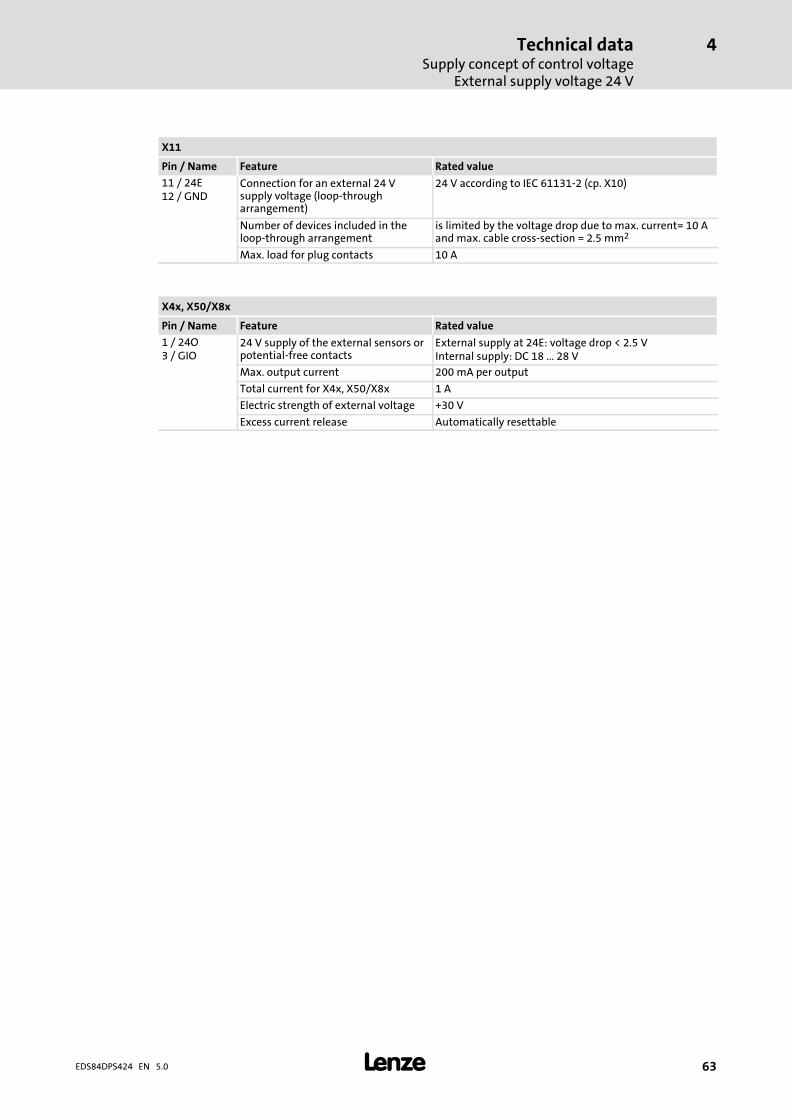
Technical dataSupply concept of control voltage
External supply voltage 24 V
4
� 63EDS84DPS424 EN 5.0
X11
Pin / Name Feature Rated value
11 / 24E12 / GND
Connection for an external 24 Vsupply voltage (loop−througharrangement)
24 V according to IEC 61131−2 (cp. X10)
Number of devices included in theloop−through arrangement
is limited by the voltage drop due to max. current= 10 Aand max. cable cross−section = 2.5 mm2
Max. load for plug contacts 10 A
X4x, X50/X8x
Pin / Name Feature Rated value
1 / 24O3 / GIO
24 V supply of the external sensors orpotential−free contacts
External supply at 24E: voltage drop < 2.5 VInternal supply: DC 18 ... 28 V
Max. output current 200 mA per output
Total current for X4x, X50/X8x 1 A
Electric strength of external voltage +30 V
Excess current release Automatically resettable
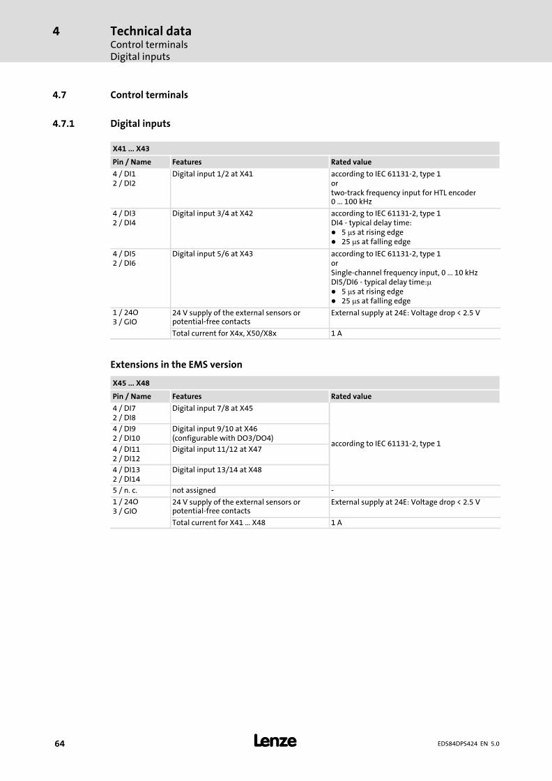
Technical dataControl terminalsDigital inputs
4
� 64 EDS84DPS424 EN 5.0
4.7 Control terminals
4.7.1 Digital inputs
X41 ... X43
Pin / Name Features Rated value
4 / DI12 / DI2
Digital input 1/2 at X41 according to IEC 61131−2, type 1ortwo−track frequency input for HTL encoder0 ... 100 kHz
4 / DI32 / DI4
Digital input 3/4 at X42 according to IEC 61131−2, type 1DI4 − typical delay time:� 5 �s at rising edge� 25 �s at falling edge
4 / DI52 / DI6
Digital input 5/6 at X43 according to IEC 61131−2, type 1orSingle−channel frequency input, 0 ... 10 kHzDI5/DI6 − typical delay time:�� 5 �s at rising edge� 25 �s at falling edge
1 / 24O3 / GIO
24 V supply of the external sensors orpotential−free contacts
External supply at 24E: Voltage drop < 2.5 V
Total current for X4x, X50/X8x 1 A
Extensions in the EMS version
X45 ... X48
Pin / Name Features Rated value
4 / DI72 / DI8
Digital input 7/8 at X45
according to IEC 61131−2, type 1
4 / DI92 / DI10
Digital input 9/10 at X46(configurable with DO3/DO4)
4 / DI112 / DI12
Digital input 11/12 at X47
4 / DI132 / DI14
Digital input 13/14 at X48
5 / n. c. not assigned −
1 / 24O3 / GIO
24 V supply of the external sensors orpotential−free contacts
External supply at 24E: Voltage drop < 2.5 V
Total current for X41 ... X48 1 A
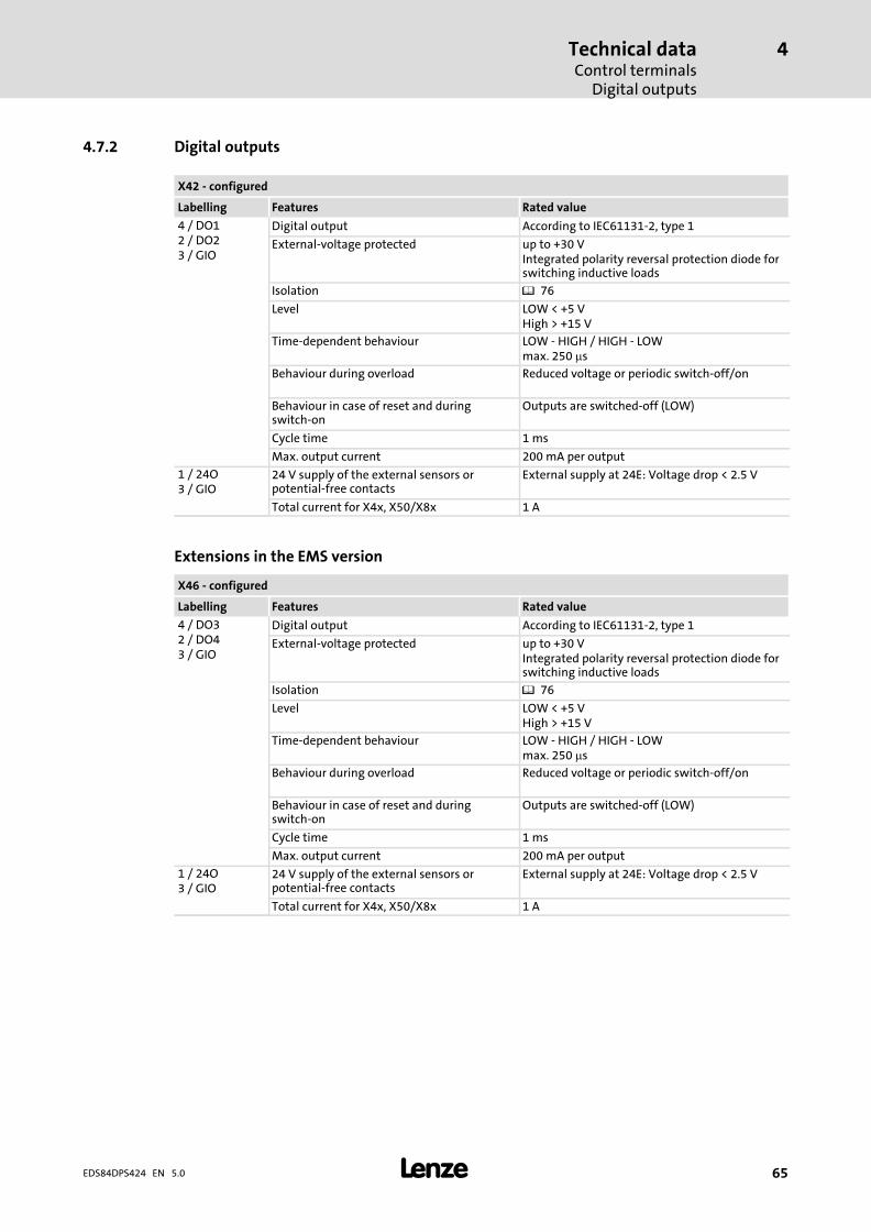
Technical dataControl terminals
Digital outputs
4
� 65EDS84DPS424 EN 5.0
4.7.2 Digital outputs
X42 − configured
Labelling Features Rated value
4 / DO12 / DO23 / GIO
Digital output According to IEC61131−2, type 1
External−voltage protected up to +30 VIntegrated polarity reversal protection diode forswitching inductive loads
Isolation � 76
Level LOW < +5 VHigh > +15 V
Time−dependent behaviour LOW − HIGH / HIGH − LOWmax. 250 �s
Behaviour during overload Reduced voltage or periodic switch−off/on
Behaviour in case of reset and duringswitch−on
Outputs are switched−off (LOW)
Cycle time 1 ms
Max. output current 200 mA per output
1 / 24O3 / GIO
24 V supply of the external sensors orpotential−free contacts
External supply at 24E: Voltage drop < 2.5 V
Total current for X4x, X50/X8x 1 A
Extensions in the EMS version
X46 − configured
Labelling Features Rated value
4 / DO32 / DO43 / GIO
Digital output According to IEC61131−2, type 1
External−voltage protected up to +30 VIntegrated polarity reversal protection diode forswitching inductive loads
Isolation � 76
Level LOW < +5 VHigh > +15 V
Time−dependent behaviour LOW − HIGH / HIGH − LOWmax. 250 �s
Behaviour during overload Reduced voltage or periodic switch−off/on
Behaviour in case of reset and duringswitch−on
Outputs are switched−off (LOW)
Cycle time 1 ms
Max. output current 200 mA per output
1 / 24O3 / GIO
24 V supply of the external sensors orpotential−free contacts
External supply at 24E: Voltage drop < 2.5 V
Total current for X4x, X50/X8x 1 A
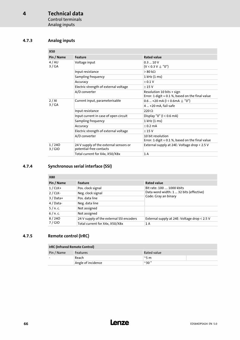
Technical dataControl terminalsAnalog inputs
4
� 66 EDS84DPS424 EN 5.0
4.7.3 Analog inputs
X50
Pin / Name Feature Rated value
4 / AU3 / GA
Voltage input 0.3 ... 10 V(V < 0.3 V � "0")
Input resistance > 80 k�
Sampling frequency 1 kHz (1 ms)
Accuracy � 0.1 V
Electric strength of external voltage � 15 V
A/D converter Resolution 10 bits + signError: 1 digit� 0.1 %, based on the final value
2 / AI3 / GA
Current input, parameterisable 0.6 ... +20 mA (I < 0.6mA � "0")
4 ... +20 mA, fail−safe
Input resistance 220 �
Input current in case of open circuit Display "0" (I < 0.6 mA)
Sampling frequency 1 kHz (1 ms)
Accuracy � 0.2 mA
Electric strength of external voltage � 15 V
A/D converter 10 bit resolutionError: 1 digit� 0.1 %, based on the final value
1 / 24O3 / GIO
24 V supply of the external sensors orpotential−free contacts
External supply at 24E: Voltage drop < 2.5 V
Total current for X4x, X50/X8x 1 A
4.7.4 Synchronous serial interface (SSI)
X80
Pin / Name Feature Rated value
1 / CLK+ Pos. clock signal Bit rate: 100 .... 1000 kbitsData word width: 1 ... 32 bits (effective)Code: Gray an binary
2 / CLK− Neg. clock signal
3 / Data+ Pos. data line
4 / Data− Neg. data line
5 / n. c. Not assigned
6 / n. c. Not assigned
8 / 24O7 / GIO
24 V supply of the external SSI encoders External supply at 24E: Voltage drop < 2.5 V
Total current for X4x, X50/X8x 1 A
4.7.5 Remote control (IrRC)
IrRC (Infrared Remote Control)
Pin / Name Features Rated value
− Reach ~5 m
Angle of incidence ~30 °
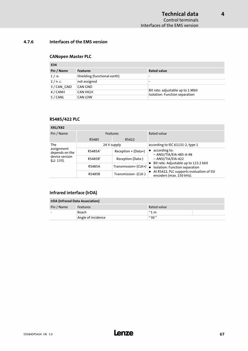
Technical dataControl terminals
Interfaces of the EMS version
4
� 67EDS84DPS424 EN 5.0
4.7.6 Interfaces of the EMS version
CANopen Master PLC
X34
Pin / Name Features Rated value
1 / � Shielding (functional earth) −
2 / n. c. not assigned −
3 / CAN_GND CAN GNDBit rate: adjustable up to 1 MbitIsolation: Function separation
4 / CANH CAN HIGH
5 / CANL CAN LOW
RS485/422 PLC
X81/X82
Pin / Name Features Rated value
RS485 RS422
Theassignmentdepends on thedevice version(� 133).
24 V supply according to IEC 61131−2, type 1
RS485A’ Reception + (Data+) � according to:– ANSI/TIA/EIA−485−A−98– ANSI/TIA/EIA−422
� Bit rate: Adjustable up to 115.2 kbit� Isolation: Function separation� At RS422, PLC supports evaluation of SSI
encoders (max. 150 kHz).
RS485B’ Reception (Data−)
RS485A Transmission+ (CLK+)
RS485B Transmission− (CLK−)
Infrared interface (IrDA)
IrDA (Infrared Data Association)
Pin / Name Features Rated value
− Reach ~1 m
Angle of incidence ~30 °
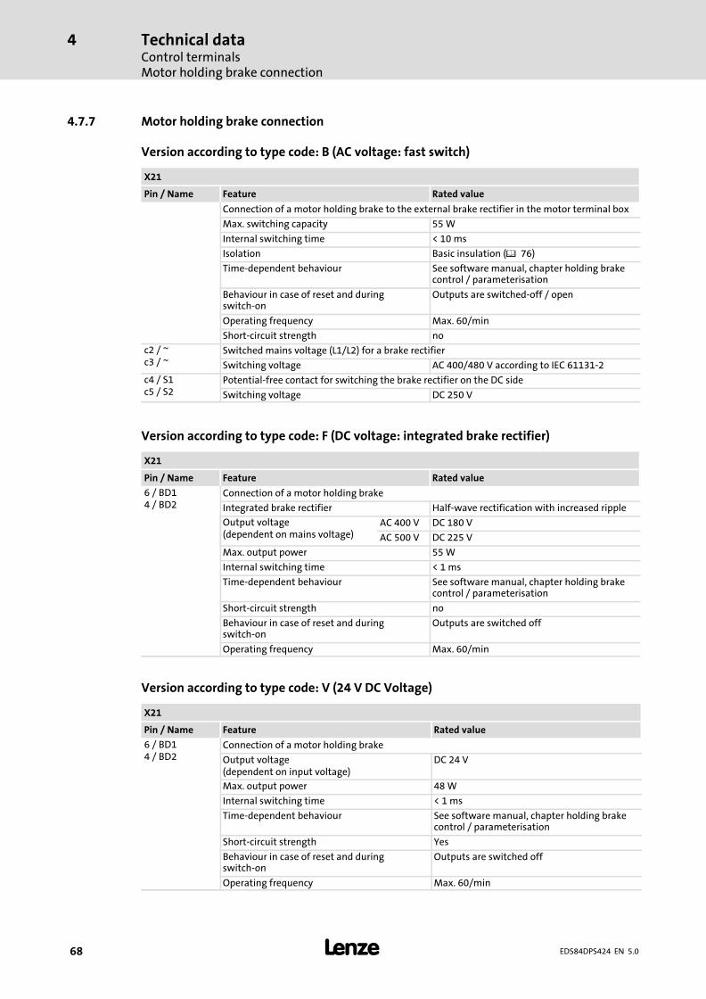
Technical dataControl terminalsMotor holding brake connection
4
� 68 EDS84DPS424 EN 5.0
4.7.7 Motor holding brake connection
Version according to type code: B (AC voltage: fast switch)
X21
Pin / Name Feature Rated value
Connection of a motor holding brake to the external brake rectifier in the motor terminal box
Max. switching capacity 55 W
Internal switching time < 10 ms
Isolation Basic insulation (� 76)
Time−dependent behaviour See software manual, chapter holding brakecontrol / parameterisation
Behaviour in case of reset and duringswitch−on
Outputs are switched−off / open
Operating frequency Max. 60/min
Short−circuit strength no
c2 / ~c3 / ~
Switched mains voltage (L1/L2) for a brake rectifier
Switching voltage AC 400/480 V according to IEC 61131−2
c4 / S1c5 / S2
Potential−free contact for switching the brake rectifier on the DC side
Switching voltage DC 250 V
Version according to type code: F (DC voltage: integrated brake rectifier)
X21
Pin / Name Feature Rated value
6 / BD14 / BD2
Connection of a motor holding brake
Integrated brake rectifier Half−wave rectification with increased ripple
Output voltage(dependent on mains voltage)
AC 400 V DC 180 V
AC 500 V DC 225 V
Max. output power 55 W
Internal switching time < 1 ms
Time−dependent behaviour See software manual, chapter holding brakecontrol / parameterisation
Short−circuit strength no
Behaviour in case of reset and duringswitch−on
Outputs are switched off
Operating frequency Max. 60/min
Version according to type code: V (24 V DC Voltage)
X21
Pin / Name Feature Rated value
6 / BD14 / BD2
Connection of a motor holding brake
Output voltage(dependent on input voltage)
DC 24 V
Max. output power 48 W
Internal switching time < 1 ms
Time−dependent behaviour See software manual, chapter holding brakecontrol / parameterisation
Short−circuit strength Yes
Behaviour in case of reset and duringswitch−on
Outputs are switched off
Operating frequency Max. 60/min
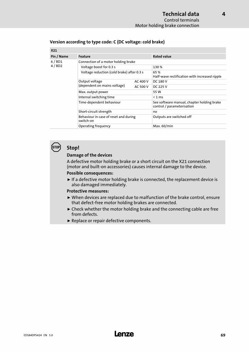
Technical dataControl terminals
Motor holding brake connection
4
� 69EDS84DPS424 EN 5.0
Version according to type code: C (DC voltage: cold brake)
X21
Pin / Name Feature Rated value
6 / BD14 / BD2
Connection of a motor holding brake
Voltage boost for 0.3 s 130 %
Voltage reduction (cold brake) after 0.3 s 65 %Half−wave rectification with increased ripple
Output voltage(dependent on mains voltage)
AC 400 V DC 180 V
AC 500 V DC 225 V
Max. output power 55 W
Internal switching time < 1 ms
Time−dependent behaviour See software manual, chapter holding brakecontrol / parameterisation
Short−circuit strength no
Behaviour in case of reset and duringswitch−on
Outputs are switched off
Operating frequency Max. 60/min
Stop!
Damage of the devices
A defective motor holding brake or a short circuit on the X21 connection(motor and built−on accessories) causes internal damage to the device.
Possible consequences:
ƒ If a defective motor holding brake is connected, the replacement device isalso damaged immediately.
Protective measures:
ƒ When devices are replaced due to malfunction of the brake control, ensurethat defect−free motor holding brakes are connected.
ƒ Check whether the motor holding brake and the connecting cable are freefrom defects.
ƒ Replace or repair defective components.
Mechanical installationImportant notes
5
� 70 EDS84DPS424 EN 5.0
5 Mechanical installation
5.1 Important notes
ƒ If the cooling air is polluted (fluff, (conductive) dust, soot, aggressive gases), takeadequate countermeasures, as e.g.:
– Cleaning of the cooling ribs on the controller in regular intervals
– Separate air guide
ƒ Possible mounting position:
– Vertically suspended
ƒ Maintain the specified free spaces above and below the controller to otherinstallations!
ƒ Ensure untroubled cooling and exhaust air flow.
ƒ In case of continuous vibrations or shocks use vibration dampers.
Depending on the size, four or six screws M6 x >10 mm are required for the mounting. Themounting location and material must ensure a durable mechanical connection.
For fastening the devices, we recommend:
ƒ M6 cheese head screw, hexagon socket, according to DIN 912/ISO 4762
ƒ M6 cheese head screw, torx, according to ISO 14579
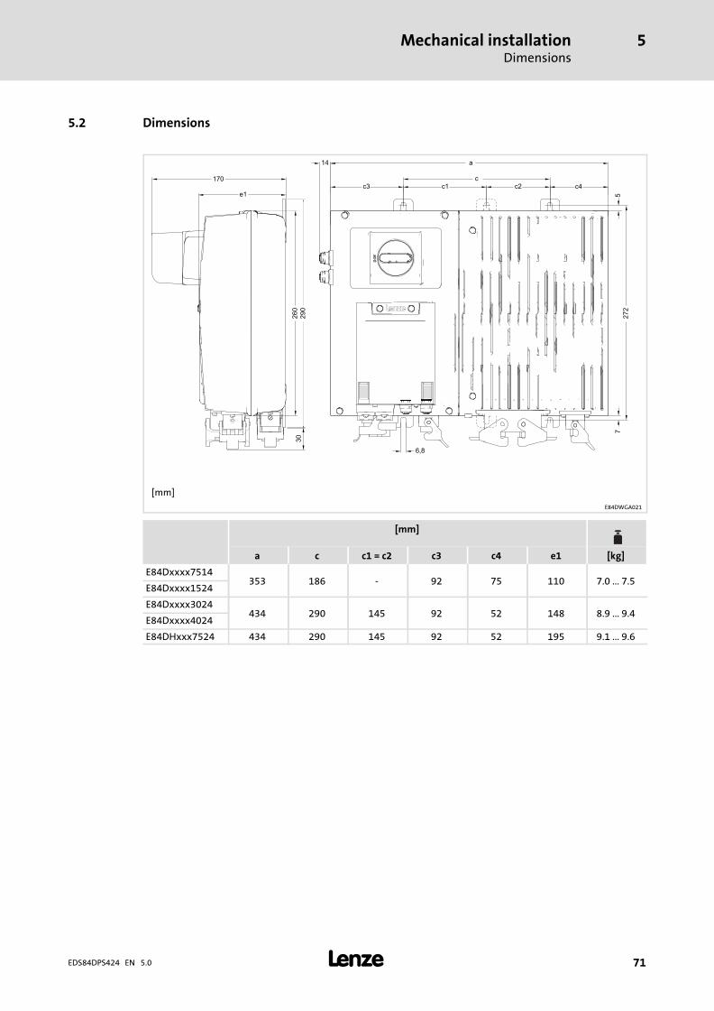
Mechanical installationDimensions
5
� 71EDS84DPS424 EN 5.0
5.2 Dimensions
[mm]
E84DWGA021
[mm]
a c c1 = c2 c3 c4 e1 [kg]
E84Dxxxx7514353 186 − 92 75 110 7.0 ... 7.5
E84Dxxxx1524
E84Dxxxx3024434 290 145 92 52 148 8.9 ... 9.4
E84Dxxxx4024
E84DHxxx7524 434 290 145 92 52 195 9.1 ... 9.6
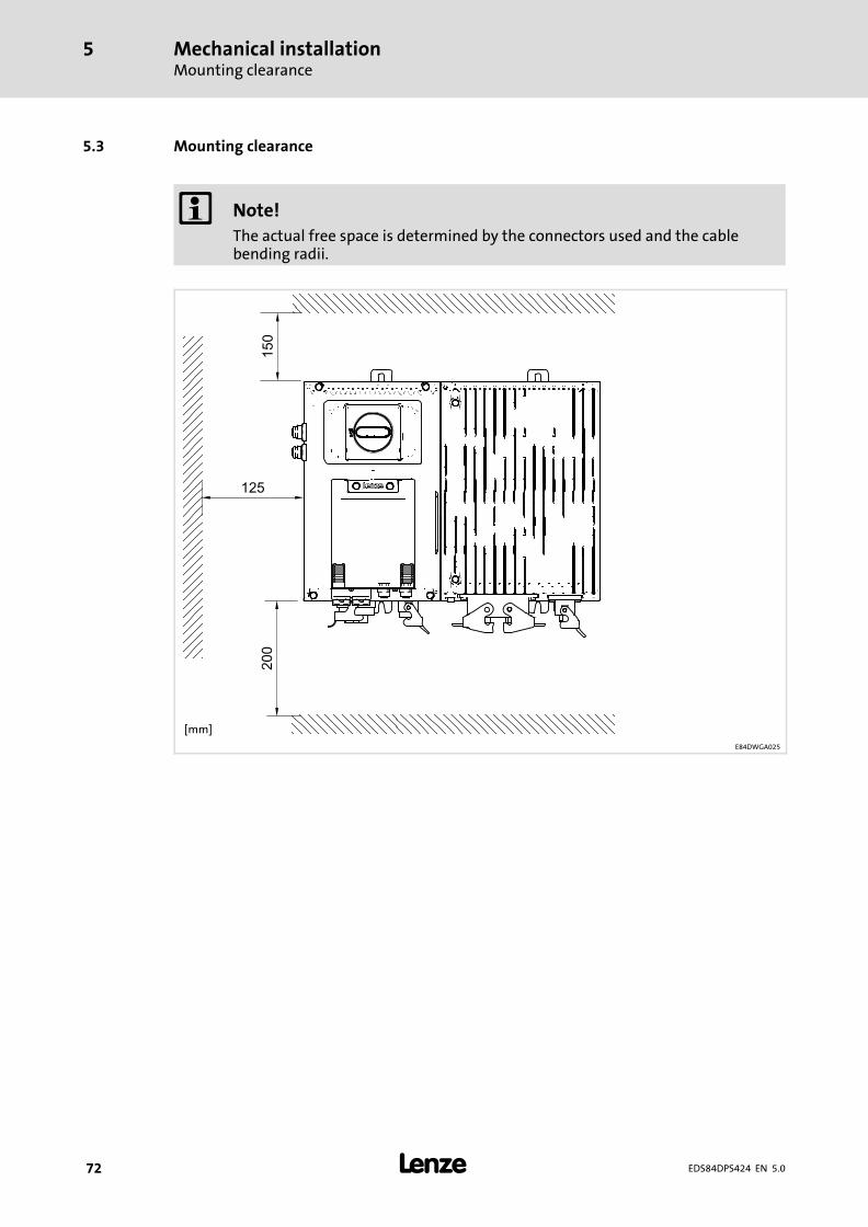
Mechanical installationMounting clearance
5
� 72 EDS84DPS424 EN 5.0
5.3 Mounting clearance
� Note!
The actual free space is determined by the connectors used and the cablebending radii.
[mm]
E84DWGA025
Electrical installation − HighLine/StateLine versionImportant notes
6
� 73EDS84DPS424 EN 5.0
6 Electrical installation − HighLine/StateLine version
6.1 Important notes
Danger!
Dangerous electrical voltage
All power terminals remain live for up to three minutes after mainsdisconnection.
Possible consequences:
ƒ Death or severe injuries when touching the power terminals.
Protective measures:
ƒ Switch off the power supply and wait for at least three minutes beforeworking on the power terminals.
ƒ Make sure that all power terminals are deenergised.
Danger!
ƒ The contacts of the power connectors X10, X11, X20 and X21 may carrydangerous voltage if the frequency inverter is connected to the mains. Thus,deenergise the frequency inverter before working on it.
ƒ Earth the device by means of X10 and by connecting it to functional earth(earthing bolt) in order to prevent injury to persons and malfunctioning.
Danger!
Dangerous voltage
The leakage current to earth (PE) is > 3.5 mA AC or > 10 mA DC.
Possible consequences:
ƒ Death or severe injuries when the device is touched in the event of a fault.
Protective measures:
ƒ Implement the actions required in the EN 61800−5−1. Especially:– Fixed installation– PE connection must conform to standards (PE conductor diameter� 10 mm2 or PE conductor must be connected twice)
Electrical installation − HighLine/StateLine versionImportant notes
6
� 74 EDS84DPS424 EN 5.0
Stop!
No device protection if the mains voltage is too high
The mains input is not internally fused.
Possible consequences:
ƒ Destruction of the device if the mains voltage is too high.
Protective measures:
ƒ Observe the maximally permissible mains voltage.
ƒ Fuse the device correctly on the supply side against mains fluctuations andvoltage peaks.
Stop!
The device contains components that can be destroyed by electrostaticdischarge!
Before working on the device, the personnel must ensure that they are free ofelectrostatic charge by using appropriate measures.
Stop!
Pluggable terminal strips or plug connections
Plugging or removing the terminal strips or plug connections during operationmay cause high voltages and arcing.
Possible consequences:
ƒ Damage of the devices
Protective measures:
ƒ Switch off device.
ƒ Only plug or remove the terminal strips or plug connections in deenergisedstatus.
� Note!
Switching on the controller motor side is permissible for safety shutdown(emergency stop) and for operation of several motors on the controller in V/foperating mode.
Please observe the following:
ƒ When switching with the controller is enabled, you can activate monitoringfunctions of the controller. If no monitoring function is activated, switchingis permissible.
ƒ The switching elements at the motor end must be rated for DC voltagesVDCmax = 800 V.
Electrical installation − HighLine/StateLine versionImportant notes
6
� 75EDS84DPS424 EN 5.0
� Note!
Only with the control element
ƒ C = service switch with protective function
the device can be disconnected from the mains voltage.
� Note!
The counter plugs of the power terminals must be equipped with connectorhousings with a vertical outgoing cable.
� Note!
ƒ It is absolutely necessary to keep the plastic caps on the connectors for thecontrol terminals and interfaces!
ƒ During transport, storage, and operation, ports not used must be sealedusing the plastic caps, in order to maintain the product features inaccordance with the technical data.
ƒ Only if this note is observed, the product features certified are ensured fordevices with a safety system.
EMC−compliant wiring
� Note!
ƒ Establish a good conductive connection to protective earth by means of acopper−braid cable (e.g. mounting surface, machine earth or building earth).
ƒ Lay control cables and data lines separately from the motor cables.
ƒ Connect the shields of the control cables and data lines at both ends.
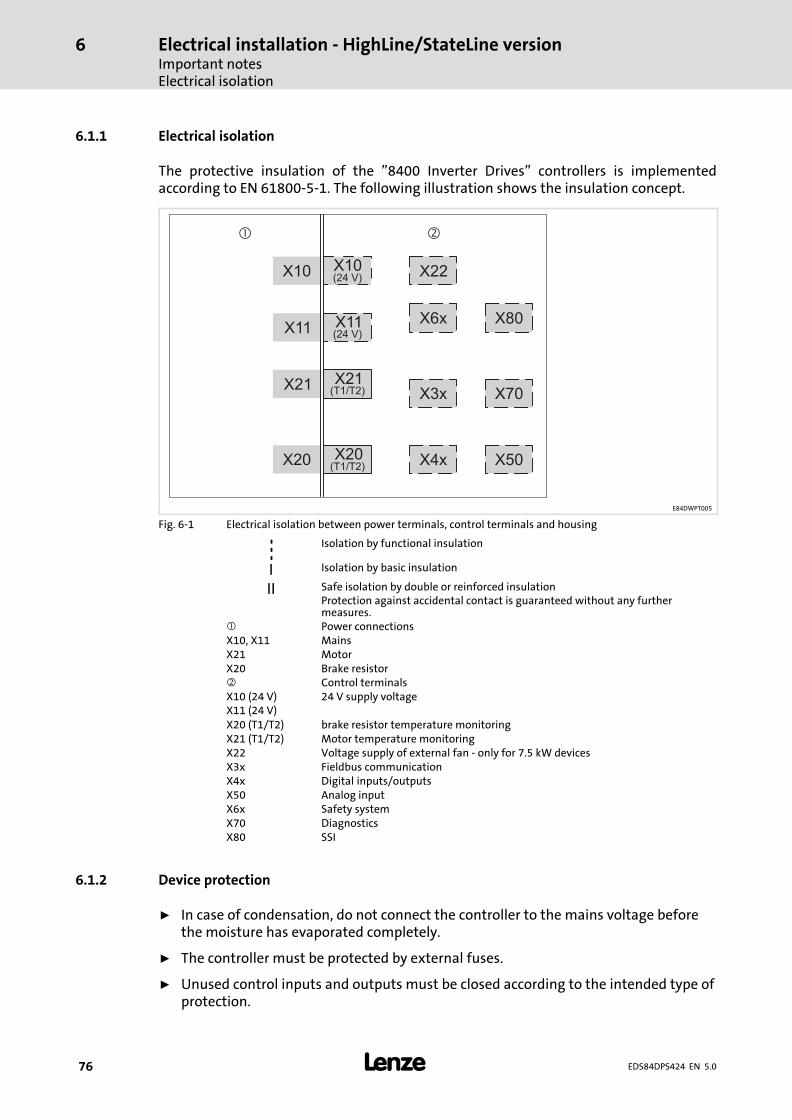
Electrical installation − HighLine/StateLine versionImportant notesElectrical isolation
6
� 76 EDS84DPS424 EN 5.0
6.1.1 Electrical isolation
The protective insulation of the "8400 Inverter Drives" controllers is implementedaccording to EN 61800−5−1. The following illustration shows the insulation concept.
X10
X11
X20
X21 X21X3x
X4x X50
X70
X80X6x
X10
X11
(24 V)
(24 V)
(T1/T2)
� �
X22
X20(T1/T2)
E84DWPT005
Fig. 6−1 Electrical isolation between power terminals, control terminals and housing
Isolation by functional insulation
I Isolation by basic insulation
II Safe isolation by double or reinforced insulationProtection against accidental contact is guaranteed without any furthermeasures.
� Power connectionsX10, X11 MainsX21 MotorX20 Brake resistor� Control terminalsX10 (24 V)X11 (24 V)
24 V supply voltage
X20 (T1/T2) brake resistor temperature monitoringX21 (T1/T2) Motor temperature monitoringX22 Voltage supply of external fan − only for 7.5 kW devicesX3x Fieldbus communicationX4x Digital inputs/outputsX50 Analog inputX6x Safety systemX70 DiagnosticsX80 SSI
6.1.2 Device protection
ƒ In case of condensation, do not connect the controller to the mains voltage beforethe moisture has evaporated completely.
ƒ The controller must be protected by external fuses.
ƒ Unused control inputs and outputs must be closed according to the intended type ofprotection.
Electrical installation − HighLine/StateLine versionImportant notes
Maximum motor cable length
6
� 77EDS84DPS424 EN 5.0
6.1.3 Maximum motor cable length
ƒ Keep the motor cable as short as possible since this has a positive effect on the drivebehaviour.
ƒ The maximally permissible motor cable length is: 20 m, shielded
– at rated mains voltage
– at a switching frequency of 8 kHz
� Note!
If the conditions for electromagnetic compatibility must be observed, thepermissible cable lengths may vary.
6.1.4 Motor protection
ƒ Extensive protection against overload:
– By overcurrent relays or temperature monitoring.
– We recommend the use of PTC thermistors or thermostats to monitor the motortemperature.
– PTC thermistors or thermostats can be connected to the controller.
– For monitoring the motor, we recommend the use of the I2xt monitoring.
ƒ Only use motors with an insulation suitable for the inverter operation:
– Insulation resistance: min. û = 1.5 kV, min. du/dt = 5 kV/�s
– When using motors with an unknown insulation resistance, please contact yourmotor supplier.
Electrical installation − HighLine/StateLine versionSafety instructions for the installation according to UL or UR
6
� 78 EDS84DPS424 EN 5.0
6.2 Safety instructions for the installation according to UL or UR
Original − English
� Warnings!
ƒ Branch circuit protection:
Suitable for use on a circuit capable of delivering not more than 200 000 rmssymmetrical amperes, 500 V maximum.– When Protected by CC, T, or J Class Fuses.
ƒ Integral solid state protection does not provide branch circuit protection.Branch circuit protection must be provided in accordance with the NationalElectrical Code and any additional local codes.
ƒ Overload Protection = 125 % of rated FLA.
ƒ Use 75 °C copper wire only, except for control circuits.
ƒ Use Class 1 wire only.
ƒ Enclosed Device, suitable for use in a UL Type 4X (Indoor) Environment.
ƒ Suitable for use in a surrounding air temperature of 45 °C, and– additionally 55 °C when de−rating rules are followed.
ƒ Suitable for use in a compartment handling conditioned air.
ƒ The device is provided with internal overload protection. For information onthe protection level of the internal overload protection for a motor load, seethe corresponding Software Manual or Online Help under the topic "Motorload monitoring (I2xt)". This function has to be activated; i. e. the reactionmust be changed from "Warning" (factory setting) to "Fault".
ƒ For information on rating and proper connection of the thermal protector(only for connection to motors having integral thermal protection), see thecorresponding Manual or Online Help.
� Warnings!
The opening of branch−circuit protective device may be an indication that afault has been interrupted.
To reduce the risk of fire or electric shock, current−carrying parts and othercomponents of the controller should be examined and replaced if damaged orequivalent.
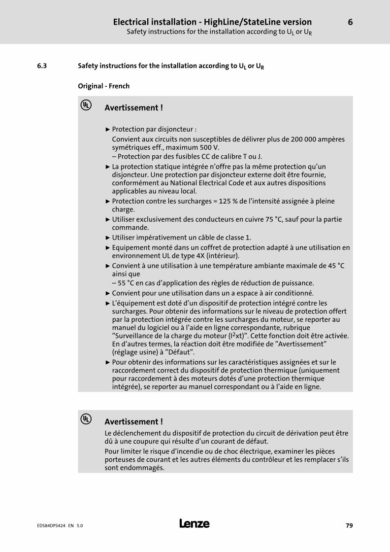
Electrical installation − HighLine/StateLine versionSafety instructions for the installation according to UL or UR
6
� 79EDS84DPS424 EN 5.0
6.3 Safety instructions for the installation according to UL or UR
Original − French
� Avertissement !
ƒ Protection par disjoncteur :
Convient aux circuits non susceptibles de délivrer plus de 200 000 ampèressymétriques eff., maximum 500 V.– Protection par des fusibles CC de calibre T ou J.
ƒ La protection statique intégrée n’offre pas la même protection qu’undisjoncteur. Une protection par disjoncteur externe doit être fournie,conformément au National Electrical Code et aux autres dispositionsapplicables au niveau local.
ƒ Protection contre les surcharges = 125 % de l’intensité assignée à pleinecharge.
ƒ Utiliser exclusivement des conducteurs en cuivre 75 °C, sauf pour la partiecommande.
ƒ Utiliser impérativement un câble de classe 1.
ƒ Equipement monté dans un coffret de protection adapté à une utilisation enenvironnement UL de type 4X (intérieur).
ƒ Convient à une utilisation à une température ambiante maximale de 45 °Cainsi que– 55 °C en cas d’application des règles de réduction de puissance.
ƒ Convient pour une utilisation dans un a espace à air conditionné.
ƒ L’équipement est doté d’un dispositif de protection intégré contre lessurcharges. Pour obtenir des informations sur le niveau de protection offertpar la protection intégrée contre les surcharges du moteur, se reporter aumanuel du logiciel ou à l’aide en ligne correspondante, rubrique"Surveillance de la charge du moteur (I2xt)". Cette fonction doit être activée.En d’autres termes, la réaction doit être modifiée de "Avertissement"(réglage usine) à "Défaut".
ƒ Pour obtenir des informations sur les caractéristiques assignées et sur leraccordement correct du dispositif de protection thermique (uniquementpour raccordement à des moteurs dotés d’une protection thermiqueintégrée), se reporter au manuel correspondant ou à l’aide en ligne.
� Avertissement !
Le déclenchement du dispositif de protection du circuit de dérivation peut êtredû à une coupure qui résulte d’un courant de défaut.
Pour limiter le risque d’incendie ou de choc électrique, examiner les piècesporteuses de courant et les autres éléments du contrôleur et les remplacer s’ilssont endommagés.
Electrical installation − HighLine/StateLine versionInstallation according to EMC (installation of a CE−typical drive system)Shielding
6
� 80 EDS84DPS424 EN 5.0
6.4 Installation according to EMC (installation of a CE−typical drive system)
Design of the cables
ƒ It is imperative to comply with the regulations concerning minimum cross−sectionsof PE conductors. The cross−section of the PE conductor must be at least as large asthe cross−section of the power connections.
ƒ The cables used must comply with the approvals required for the location (e.g. UL).
6.4.1 Shielding
Requirements
ƒ The effectiveness of a shielded cable is reached by:
– Providing a good shield connection through large−surface shield contact.
– Using only braided shields with low shield resistance made of tin−plated ornickel−plated copper braid.
– Using braided shields with an overlap rate > 70 % and an overlap angle of 90 °.
– Keeping unshielded cable ends as short as possible.
Use system cables or shielded cables for these connections:
ƒ Motor
ƒ External brake resistor (� Mounting Instructions of the brake resistor)
ƒ Motor holding brake (shielding is required when being integrated into the motorcable; connection to optional motor brake control)
ƒ Motor temperature monitoring
ƒ Analog signals (inputs and outputs; single−sided shield connection to the controller)
ƒ Fieldbus communication (e.g. CANopen ,PROFIBUS, PROFINET, ...)
ƒ Safety system
ƒ CAN on board
The following connections need not be shielded:
ƒ Mains
ƒ 24−V supply
ƒ Digital signals (inputs and outputs).
– We recommend to use shielded cables for a cable length from approximately 5 mon or in environments with strong interferences.
Connection system
ƒ Directly apply the shielding in the plug.
– Extensively apply the shielding and ensure electrical conductivity.
– If required, additionally connect the shield to the cable clamp rail.
Electrical installation − HighLine/StateLine versionInstallation according to EMC (installation of a CE−typical drive system)
Motor cable
6
� 81EDS84DPS424 EN 5.0
6.4.2 Motor cable
ƒ Only use shielded motor cables with braids made of tinned or nickel−plated copper.Shields made of steel braids are not suitable.
– The overlap rate of the braid must be at least 70 % with an overlap angle of 90 °.
ƒ The cables used must correspond to the requirements at the location (e.g.EN 60204−1).
ƒ Use Lenze system cables.
ƒ Extensively apply the shielding in the plug and attach it in a way which ensureselectrical conductivity.
ƒ The motor cable is optimally installed if
– it is separated from mains cables and control cables,
– it only crosses mains cables and control cables at right angles,
– it is not interrupted.
ƒ If the motor cable must be opened all the same (e.g. due to chokes, contactors, orterminals):
– The unshielded cable ends may not be longer than 100 mm (depending on thecable cross−section).
– Install chokes, contactors, terminals etc. spatially separated from othercomponents (with a min. distance of 100 mm).
– Install the shield of the motor cable directly before and behind the point ofseparation to the mounting plate with a large surface.
ƒ Connect the shield with a large surface to PE in the terminal box of the motor at themotor housing.
– Metal EMC cable glands at the motor terminal box ensure a large surfaceconnection of the shield with the motor housing.
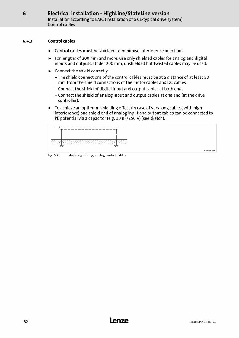
Electrical installation − HighLine/StateLine versionInstallation according to EMC (installation of a CE−typical drive system)Control cables
6
� 82 EDS84DPS424 EN 5.0
6.4.3 Control cables
ƒ Control cables must be shielded to minimise interference injections.
ƒ For lengths of 200 mm and more, use only shielded cables for analog and digitalinputs and outputs. Under 200 mm, unshielded but twisted cables may be used.
ƒ Connect the shield correctly:
– The shield connections of the control cables must be at a distance of at least 50mm from the shield connections of the motor cables and DC cables.
– Connect the shield of digital input and output cables at both ends.
– Connect the shield of analog input and output cables at one end (at the drivecontroller).
ƒ To achieve an optimum shielding effect (in case of very long cables, with highinterference) one shield end of analog input and output cables can be connected toPE potential via a capacitor (e.g. 10 nF/250 V) (see sketch).
9300vec043
Fig. 6−2 Shielding of long, analog control cables
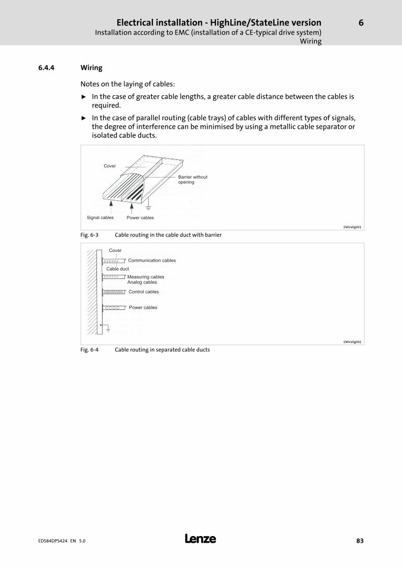
Electrical installation − HighLine/StateLine versionInstallation according to EMC (installation of a CE−typical drive system)
Wiring
6
� 83EDS84DPS424 EN 5.0
6.4.4 Wiring
Notes on the laying of cables:
ƒ In the case of greater cable lengths, a greater cable distance between the cables isrequired.
ƒ In the case of parallel routing (cable trays) of cables with different types of signals,the degree of interference can be minimised by using a metallic cable separator orisolated cable ducts.
Cover
Barrier withoutopening
Power cablesSignal cables
EMVallg001
Fig. 6−3 Cable routing in the cable duct with barrier
Cover
Communication cables
Cable duct
Measuring cablesAnalog cables
Control cables
Power cables
EMVallg002
Fig. 6−4 Cable routing in separated cable ducts
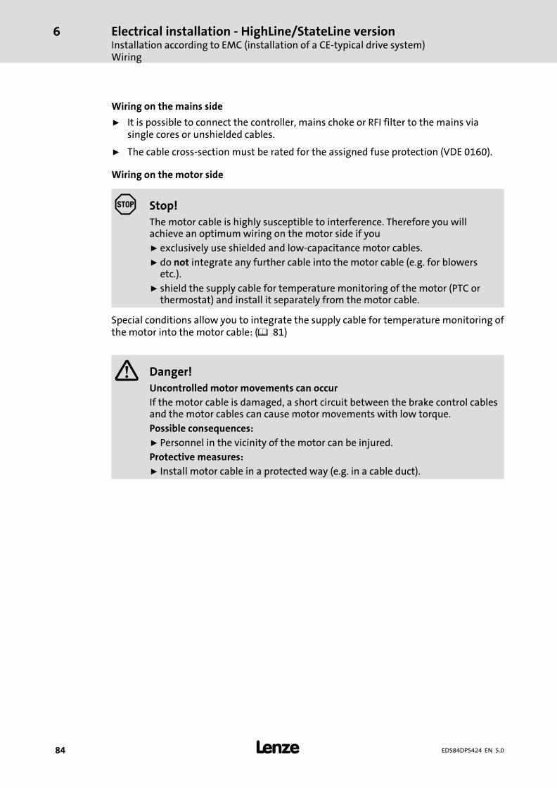
Electrical installation − HighLine/StateLine versionInstallation according to EMC (installation of a CE−typical drive system)Wiring
6
� 84 EDS84DPS424 EN 5.0
Wiring on the mains side
ƒ It is possible to connect the controller, mains choke or RFI filter to the mains viasingle cores or unshielded cables.
ƒ The cable cross−section must be rated for the assigned fuse protection (VDE 0160).
Wiring on the motor side
Stop!
The motor cable is highly susceptible to interference. Therefore you willachieve an optimum wiring on the motor side if you
ƒ exclusively use shielded and low−capacitance motor cables.
ƒ do not integrate any further cable into the motor cable (e.g. for blowersetc.).
ƒ shield the supply cable for temperature monitoring of the motor (PTC orthermostat) and install it separately from the motor cable.
Special conditions allow you to integrate the supply cable for temperature monitoring ofthe motor into the motor cable: (� 81)
� Danger!
Uncontrolled motor movements can occur
If the motor cable is damaged, a short circuit between the brake control cablesand the motor cables can cause motor movements with low torque.
Possible consequences:
ƒ Personnel in the vicinity of the motor can be injured.
Protective measures:
ƒ Install motor cable in a protected way (e.g. in a cable duct).
Electrical installation − HighLine/StateLine versionInstallation according to EMC (installation of a CE−typical drive system)
Detecting and eliminating EMC interferences
6
� 85EDS84DPS424 EN 5.0
6.4.5 Detecting and eliminating EMC interferences
Fault Cause Remedy
Interferences of analogsetpoints of your own orother devices andmeasuring systems
Unshielded motor cable Use shielded motor cable
Shield contact is not extensive enough Carry out optimal shielding as specified
Shield of the motor cable is interruptedby terminal strips, switched, etc.
� Separate components from othercomponent part with a minimumdistance of 100 mm
� Use motor choke/motor filter
Install additional unshielded cablesinside the motor cable (e.g. for motortemperature monitoring)
Install and shield additional cablesseparately
Too long and unshielded cable ends ofthe motor cable
Shorten unshielded cable ends tomaximally 40 mm
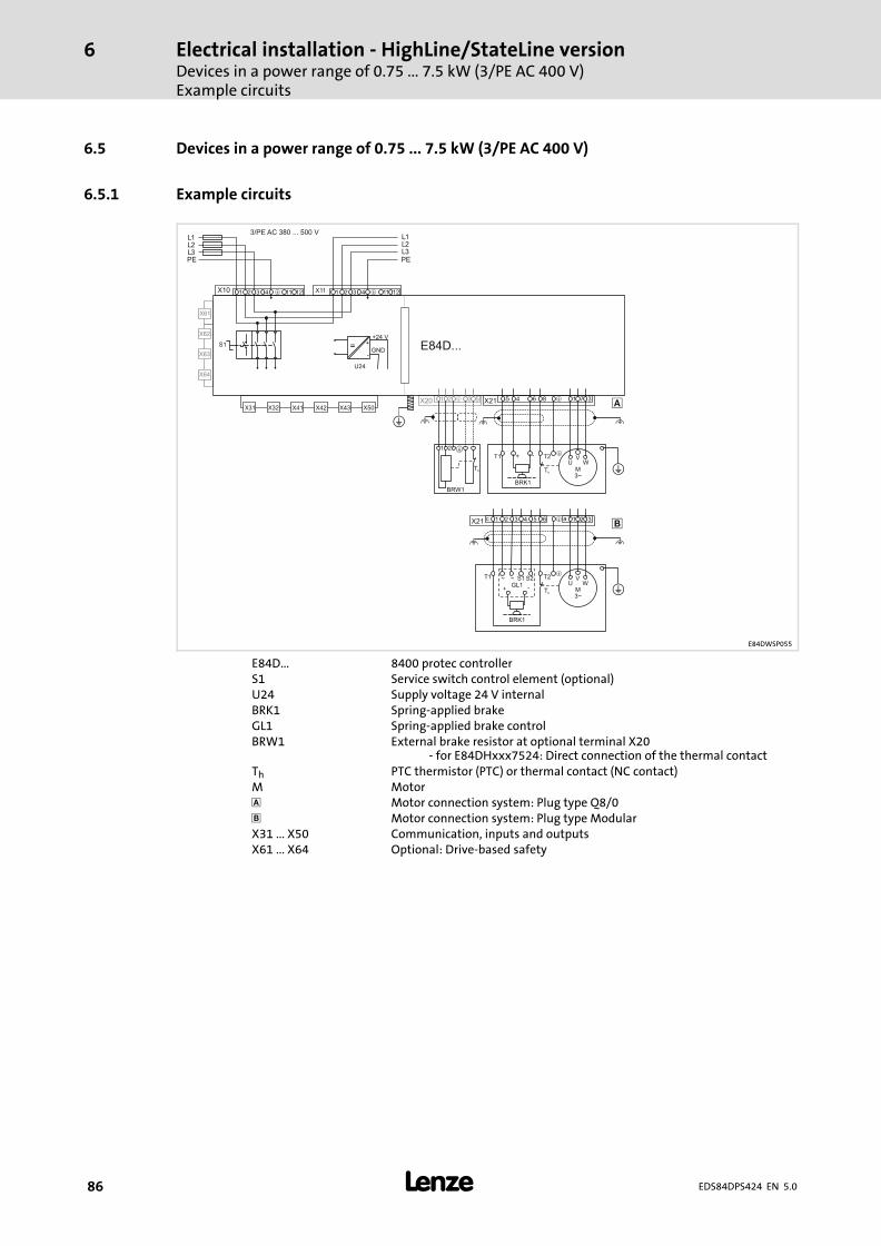
Electrical installation − HighLine/StateLine versionDevices in a power range of 0.75 ... 7.5 kW (3/PE AC 400 V)Example circuits
6
� 86 EDS84DPS424 EN 5.0
6.5 Devices in a power range of 0.75 ... 7.5 kW (3/PE AC 400 V)
6.5.1 Example circuits
5 84 6 1 7 3X21 �
M3~
UV
W
�
�BRK1
T1 T2
Th
+ -
�
64 1 2 3X21 �c 1 2 3 a5
M3~
UV
W
�
�T1 T2
Th
BRK1
+ -
~ ~ S1 S2GL1
�
1 32 5X20 �
X50X43X42X41X32X31
X62
X63
X64
X61
E84D...
L1L2L3PE
3/PE AC 380 ... 500 VL1L2L3PE
�
1 112 3 4 12�X10
Th
BRW1
1 2 �
1 112 3 4 12�X11
S1 +
-
+24 V
GND
U24
=
E84DWSP055
E84D... 8400 protec controllerS1 Service switch control element (optional)U24 Supply voltage 24 V internalBRK1 Spring−applied brakeGL1 Spring−applied brake controlBRW1 External brake resistor at optional terminal X20
− for E84DHxxx7524: Direct connection of the thermal contactTh PTC thermistor (PTC) or thermal contact (NC contact)M Motor� Motor connection system: Plug type Q8/0 Motor connection system: Plug type ModularX31 ... X50 Communication, inputs and outputsX61 ... X64 Optional: Drive−based safety
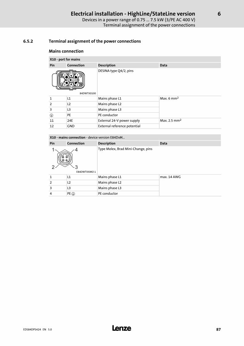
Electrical installation − HighLine/StateLine versionDevices in a power range of 0.75 ... 7.5 kW (3/PE AC 400 V)
Terminal assignment of the power connections
6
� 87EDS84DPS424 EN 5.0
6.5.2 Terminal assignment of the power connections
Mains connection
X10 − port for mains
Pin Connection Description Data
DESINA type Q4/2, pins
84DWTX0100
1 L1 Mains phase L1 Max. 6 mm2
2 L2 Mains phase L2
3 L3 Mains phase L3
� PE PE conductor
11 24E External 24−V power supply Max. 2.5 mm2
12 GND External reference potential
X10 − mains connection − device version E84DxH...
Pin Connection Description Data
1 4
32
Type Molex, Brad Mini−Change, pins
E84DWTXXMO 1
1 L1 Mains phase L1 max. 14 AWG
2 L2 Mains phase L2
3 L3 Mains phase L3
4 PE � PE conductor
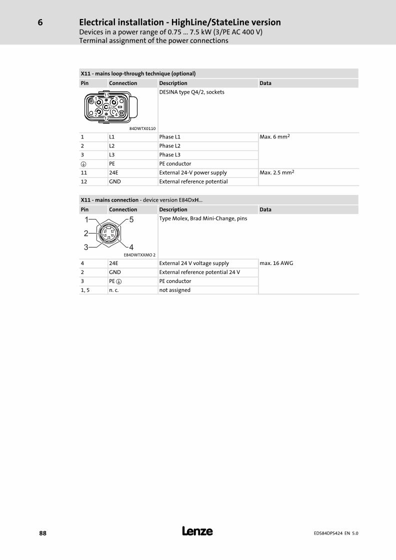
Electrical installation − HighLine/StateLine versionDevices in a power range of 0.75 ... 7.5 kW (3/PE AC 400 V)Terminal assignment of the power connections
6
� 88 EDS84DPS424 EN 5.0
X11 − mains loop−through technique (optional)
Pin Connection Description Data
DESINA type Q4/2, sockets
84DWTX0110
1 L1 Phase L1 Max. 6 mm2
2 L2 Phase L2
3 L3 Phase L3
� PE PE conductor
11 24E External 24−V power supply Max. 2.5 mm2
12 GND External reference potential
X11 − mains connection − device version E84DxH...
Pin Connection Description Data
5
43
2
1 Type Molex, Brad Mini−Change, pins
E84DWTXXMO 2
4 24E External 24 V voltage supply max. 16 AWG
2 GND External reference potential 24 V
3 PE � PE conductor
1, 5 n. c. not assigned
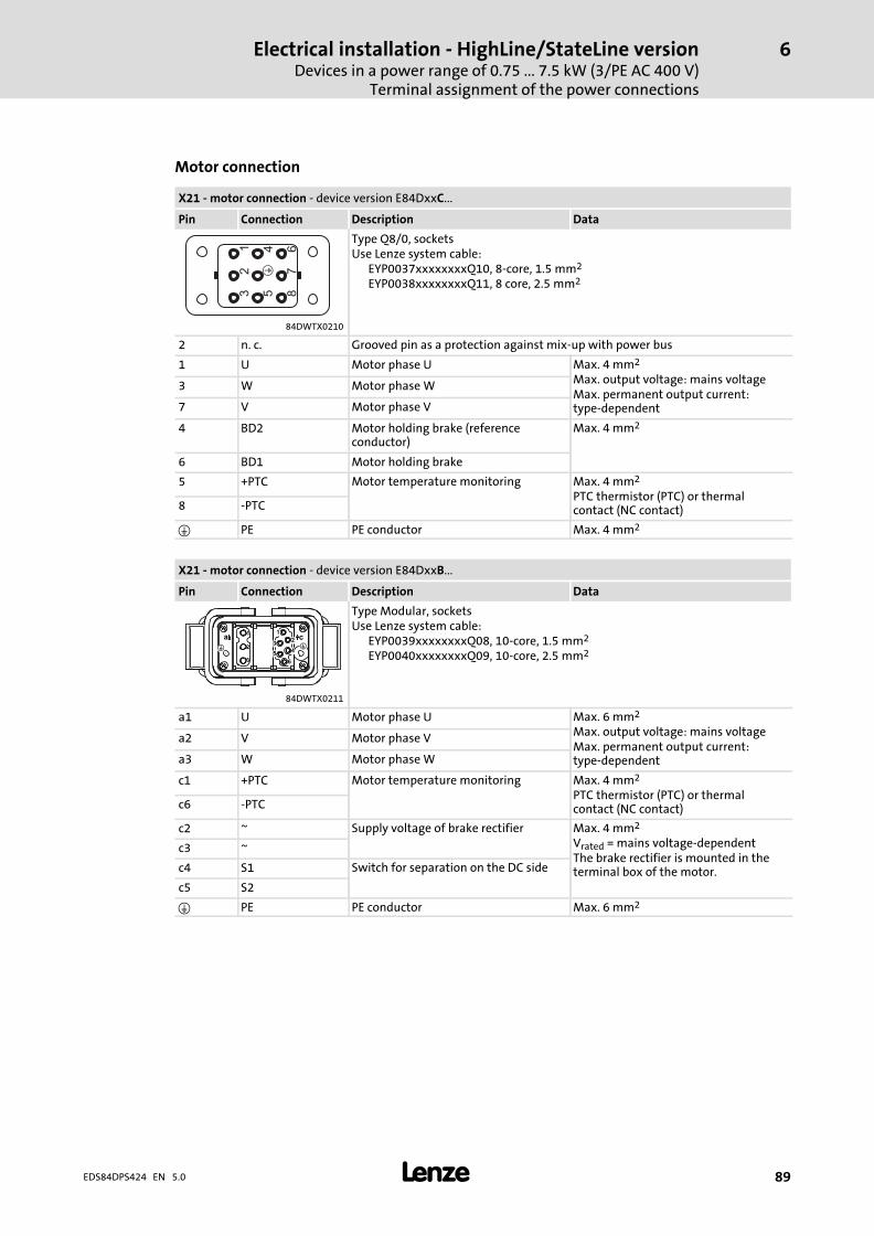
Electrical installation − HighLine/StateLine versionDevices in a power range of 0.75 ... 7.5 kW (3/PE AC 400 V)
Terminal assignment of the power connections
6
� 89EDS84DPS424 EN 5.0
Motor connection
X21 − motor connection − device version E84DxxC...
Pin Connection Description Data
12
3
45
67
8
�
Type Q8/0, socketsUse Lenze system cable:
EYP0037xxxxxxxxQ10, 8−core, 1.5 mm2
EYP0038xxxxxxxxQ11, 8 core, 2.5 mm2
84DWTX0210
2 n. c. Grooved pin as a protection against mix−up with power bus
1 U Motor phase U Max. 4 mm2
Max. output voltage: mains voltageMax. permanent output current:type−dependent
3 W Motor phase W
7 V Motor phase V
4 BD2 Motor holding brake (referenceconductor)
Max. 4 mm2
6 BD1 Motor holding brake
5 +PTC Motor temperature monitoring Max. 4 mm2
PTC thermistor (PTC) or thermalcontact (NC contact)8 −PTC
� PE PE conductor Max. 4 mm2
X21 − motor connection − device version E84DxxB...
Pin Connection Description Data
Type Modular, socketsUse Lenze system cable:
EYP0039xxxxxxxxQ08, 10−core, 1.5 mm2
EYP0040xxxxxxxxQ09, 10−core, 2.5 mm2
84DWTX0211
a1 U Motor phase U Max. 6 mm2
Max. output voltage: mains voltageMax. permanent output current:type−dependent
a2 V Motor phase V
a3 W Motor phase W
c1 +PTC Motor temperature monitoring Max. 4 mm2
PTC thermistor (PTC) or thermalcontact (NC contact)c6 −PTC
c2 ~ Supply voltage of brake rectifier Max. 4 mm2
Vrated = mains voltage−dependentThe brake rectifier is mounted in theterminal box of the motor.
c3 ~
c4 S1 Switch for separation on the DC side
c5 S2
� PE PE conductor Max. 6 mm2
Electrical installation − HighLine/StateLine versionDevices in a power range of 0.75 ... 7.5 kW (3/PE AC 400 V)Terminal assignment of the power connections
6
� 90 EDS84DPS424 EN 5.0
Stop!
Damage of the devices
A defective motor holding brake or a short circuit on the X21 connection(motor and built−on accessories) causes internal damage to the device.
Possible consequences:
ƒ If a defective motor holding brake is connected, the replacement device isalso damaged immediately.
Protective measures:
ƒ When devices are replaced due to malfunction of the brake control, ensurethat defect−free motor holding brakes are connected.
ƒ Check whether the motor holding brake and the connecting cable are freefrom defects.
ƒ Replace or repair defective components.
� Note!
In the Lenze setting, the temperature monitoring of the motor is activated! Tostart motors without thermal detectors, the response of the motortemperature monitoring must be deactivated (C00585). Alternatively, a wirejumper between +PTC and −PTC can be used to simulate a normaltemperature.
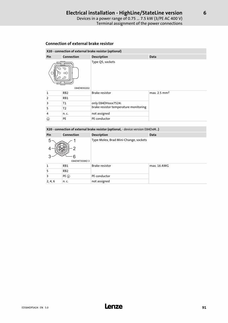
Electrical installation − HighLine/StateLine versionDevices in a power range of 0.75 ... 7.5 kW (3/PE AC 400 V)
Terminal assignment of the power connections
6
� 91EDS84DPS424 EN 5.0
Connection of external brake resistor
X20 − connection of external brake resistor (optional)
Pin Connection Description Data
Type Q5, sockets
E84DWX0202
1 RB2 Brake resistor max. 2.5 mm2
2 RB1
3 T1 only E84DHxxx7524:brake resistor temperature monitoring5 T2
4 n. c. not assigned
� PE PE conductor
X20 − connection of external brake resistor (optional, − device version E84DxH...)
Pin Connection Description Data
5 1
2
63
4
Type Molex, Brad Mini−Change, sockets
E84DWTXXMO 3
1 RB1 Brake resistor max. 16 AWG
5 RB2
3 PE � PE conductor
2, 4, 6 n. c. not assigned
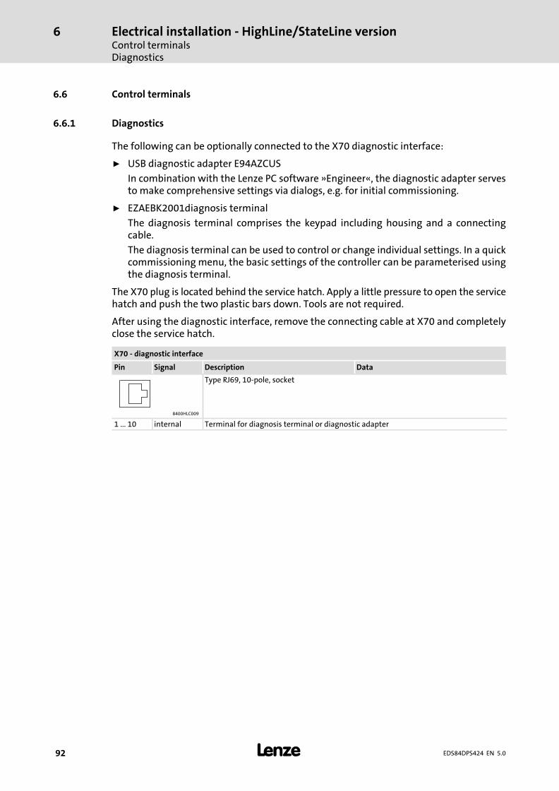
Electrical installation − HighLine/StateLine versionControl terminalsDiagnostics
6
� 92 EDS84DPS424 EN 5.0
6.6 Control terminals
6.6.1 Diagnostics
The following can be optionally connected to the X70 diagnostic interface:
ƒ USB diagnostic adapter E94AZCUS
In combination with the Lenze PC software »Engineer«, the diagnostic adapter servesto make comprehensive settings via dialogs, e.g. for initial commissioning.
ƒ EZAEBK2001diagnosis terminal
The diagnosis terminal comprises the keypad including housing and a connectingcable.
The diagnosis terminal can be used to control or change individual settings. In a quickcommissioning menu, the basic settings of the controller can be parameterised usingthe diagnosis terminal.
The X70 plug is located behind the service hatch. Apply a little pressure to open the servicehatch and push the two plastic bars down. Tools are not required.
After using the diagnostic interface, remove the connecting cable at X70 and completelyclose the service hatch.
X70 − diagnostic interface
Pin Signal Description Data
Type RJ69, 10−pole, socket
8400HLC009
1 ... 10 internal Terminal for diagnosis terminal or diagnostic adapter
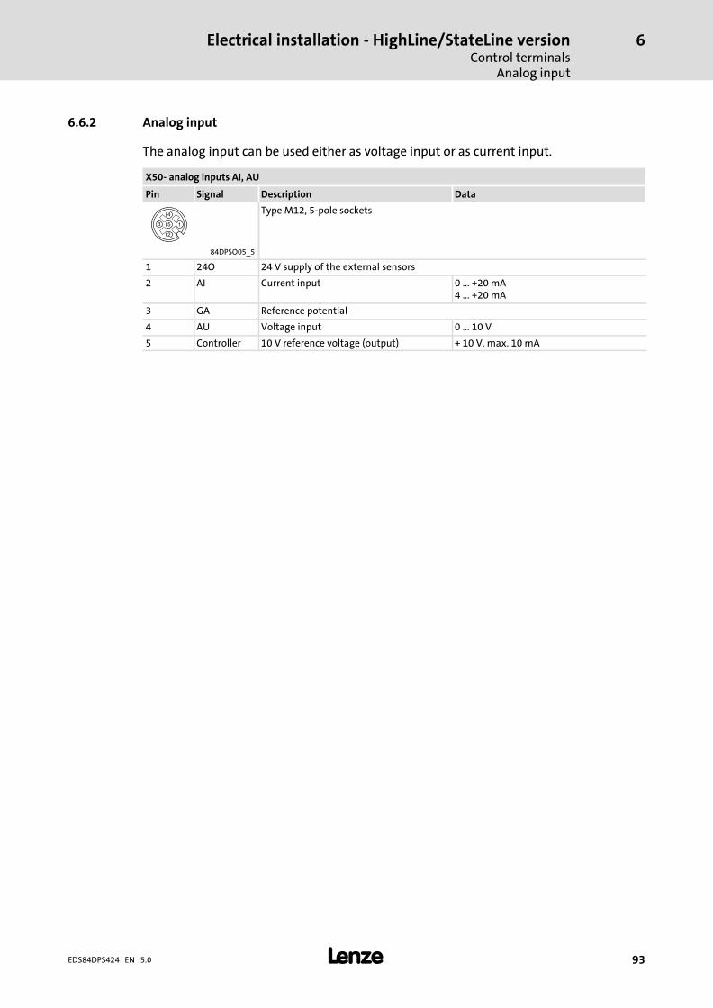
Electrical installation − HighLine/StateLine versionControl terminals
Analog input
6
� 93EDS84DPS424 EN 5.0
6.6.2 Analog input
The analog input can be used either as voltage input or as current input.
X50− analog inputs AI, AU
Pin Signal Description Data
Type M12, 5−pole sockets
84DPSO05_5
1 24O 24 V supply of the external sensors
2 AI Current input 0 ... +20 mA4 ... +20 mA
3 GA Reference potential
4 AU Voltage input 0 ... 10 V
5 Controller 10 V reference voltage (output) + 10 V, max. 10 mA
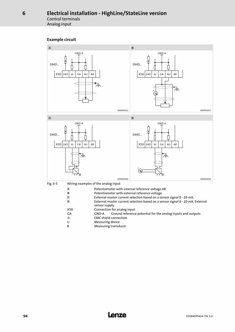
Electrical installation − HighLine/StateLine versionControl terminalsAnalog input
6
� 94 EDS84DPS424 EN 5.0
Example circuit
�
GND-A
X50 24O
E84D...
GAAI AU AR
GND-A
X50 24O
E84D...
GAAI AU AR
=-+
8400DAI012 8400DAI013
� �
GND-A
X50 24O
E84D...
GAAI AU AR
B
GND-A
X50 24O
E84D...
GAAI AU AR
B=
-+
8400DAI009 8400DAI092
Fig. 6−5 Wiring examples of the analog input
� Potentiometer with internal reference voltage AR Potentiometer with external reference voltage� External master current selection based on a sensor signal 0 − 20 mA.� External master current selection based on a sensor signal 0 − 20 mA. External
sensor supply.X50 Connection for analog inputGA GND−A Ground reference potential for the analog inputs and outputs� EMC shield connectionU Measuring deviceB Measuring transducer
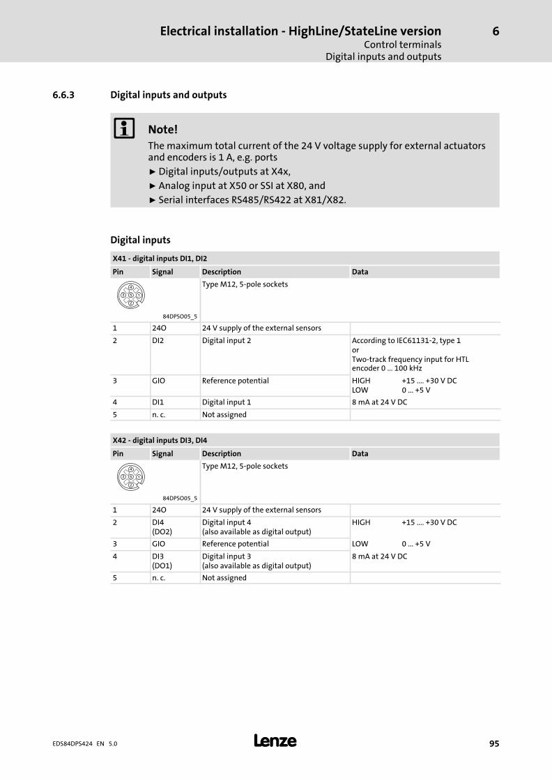
Electrical installation − HighLine/StateLine versionControl terminals
Digital inputs and outputs
6
� 95EDS84DPS424 EN 5.0
6.6.3 Digital inputs and outputs
� Note!
The maximum total current of the 24 V voltage supply for external actuatorsand encoders is 1 A, e.g. ports
ƒ Digital inputs/outputs at X4x,
ƒ Analog input at X50 or SSI at X80, and
ƒ Serial interfaces RS485/RS422 at X81/X82.
Digital inputs
X41 − digital inputs DI1, DI2
Pin Signal Description Data
Type M12, 5−pole sockets
84DPSO05_5
1 24O 24 V supply of the external sensors
2 DI2 Digital input 2 According to IEC61131−2, type 1orTwo−track frequency input for HTLencoder 0 ... 100 kHz
3 GIO Reference potential HIGHLOW
+15 .... +30 V DC0 ... +5 V
4 DI1 Digital input 1 8 mA at 24 V DC
5 n. c. Not assigned
X42 − digital inputs DI3, DI4
Pin Signal Description Data
Type M12, 5−pole sockets
84DPSO05_5
1 24O 24 V supply of the external sensors
2 DI4(DO2)
Digital input 4(also available as digital output)
HIGH +15 .... +30 V DC
3 GIO Reference potential LOW 0 ... +5 V
4 DI3(DO1)
Digital input 3(also available as digital output)
8 mA at 24 V DC
5 n. c. Not assigned
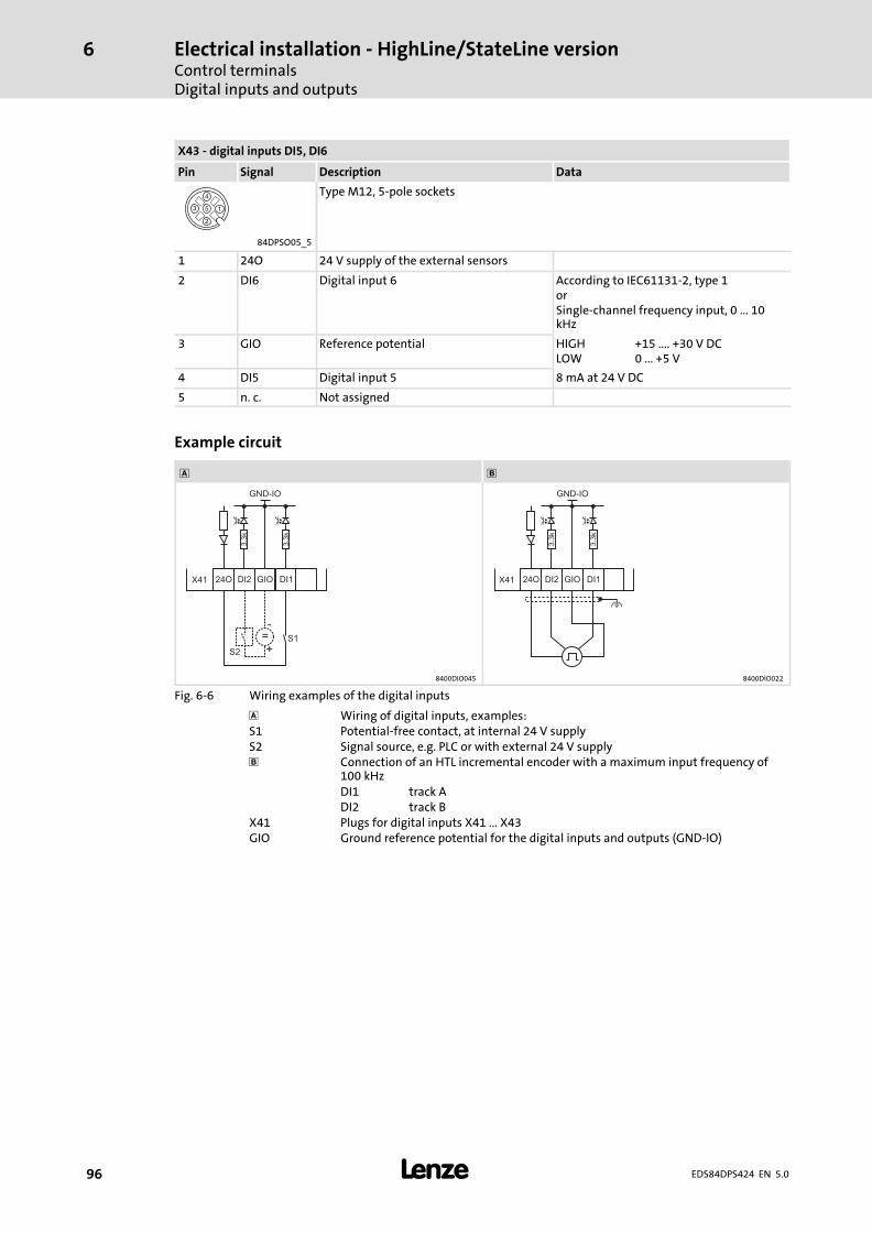
Electrical installation − HighLine/StateLine versionControl terminalsDigital inputs and outputs
6
� 96 EDS84DPS424 EN 5.0
X43 − digital inputs DI5, DI6
Pin Signal Description Data
Type M12, 5−pole sockets
84DPSO05_5
1 24O 24 V supply of the external sensors
2 DI6 Digital input 6 According to IEC61131−2, type 1orSingle−channel frequency input, 0 ... 10kHz
3 GIO Reference potential HIGHLOW
+15 .... +30 V DC0 ... +5 V
4 DI5 Digital input 5 8 mA at 24 V DC
5 n. c. Not assigned
Example circuit
�
DI1
S1
X41
GND-IO
GIO24O
3.3
k
3.3
k
DI2
S2
=-
+
DI1X41
GND-IO
GIO24O
3.3
k
3.3
k
DI2
8400DIO045 8400DIO022
Fig. 6−6 Wiring examples of the digital inputs
� Wiring of digital inputs, examples:S1 Potential−free contact, at internal 24 V supplyS2 Signal source, e.g. PLC or with external 24 V supply Connection of an HTL incremental encoder with a maximum input frequency of
100 kHzDI1 track ADI2 track B
X41 Plugs for digital inputs X41 ... X43GIO Ground reference potential for the digital inputs and outputs (GND−IO)
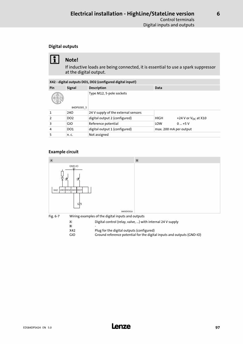
Electrical installation − HighLine/StateLine versionControl terminals
Digital inputs and outputs
6
� 97EDS84DPS424 EN 5.0
Digital outputs
� Note!
If inductive loads are being connected, it is essential to use a spark suppressorat the digital output.
X42 − digital outputs DO1, DO2 (configured digital input!)
Pin Signal Description Data
Type M12, 5−pole sockets
84DPSO05_5
1 24O 24 V supply of the external sensors
2 DO2 digital output 2 (configured) HIGH +24 V or VDC at X10
3 GIO Reference potential LOW 0 ... +5 V
4 DO1 digital output 1 (configured) max. 200 mA per output
5 n. c. Not assigned
Example circuit
�
DO1X42
GND-IO
GIO24O DO2
8400DIO016
Fig. 6−7 Wiring examples of the digital inputs and outputs
� Digital control (relay, valve, ...) with internal 24 V supply −X42 Plug for the digital outputs (configured)GIO Ground reference potential for the digital inputs and outputs (GND−IO)
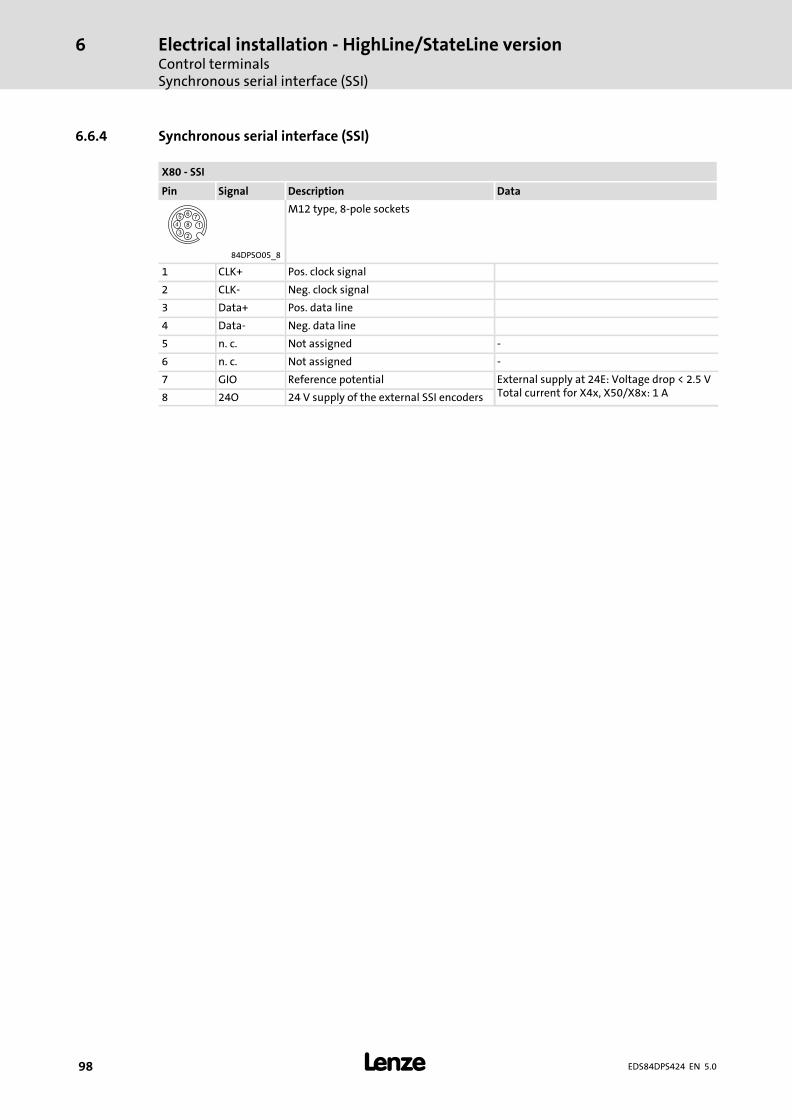
Electrical installation − HighLine/StateLine versionControl terminalsSynchronous serial interface (SSI)
6
� 98 EDS84DPS424 EN 5.0
6.6.4 Synchronous serial interface (SSI)
X80 − SSI
Pin Signal Description Data
M12 type, 8−pole sockets
84DPSO05_8
1 CLK+ Pos. clock signal
2 CLK− Neg. clock signal
3 Data+ Pos. data line
4 Data− Neg. data line
5 n. c. Not assigned −
6 n. c. Not assigned −
7 GIO Reference potential External supply at 24E: Voltage drop < 2.5 VTotal current for X4x, X50/X8x: 1 A8 24O 24 V supply of the external SSI encoders
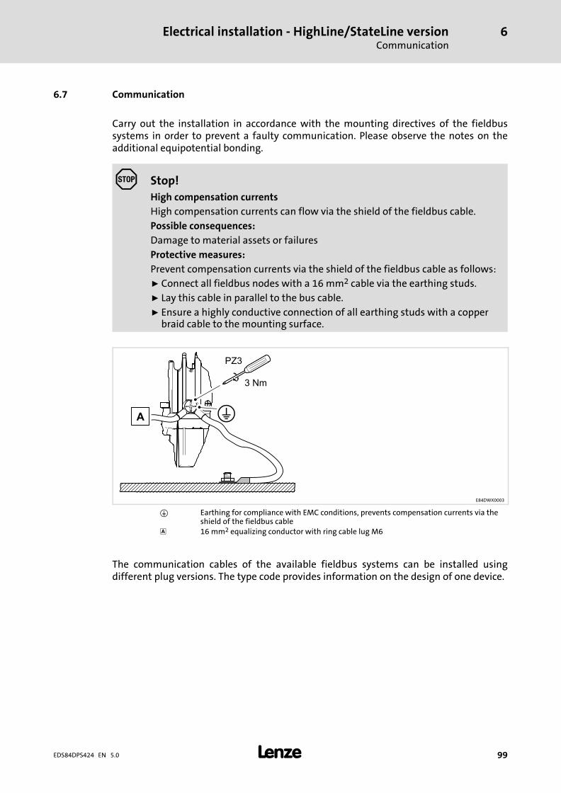
Electrical installation − HighLine/StateLine versionCommunication
6
� 99EDS84DPS424 EN 5.0
6.7 Communication
Carry out the installation in accordance with the mounting directives of the fieldbussystems in order to prevent a faulty communication. Please observe the notes on theadditional equipotential bonding.
Stop!
High compensation currents
High compensation currents can flow via the shield of the fieldbus cable.
Possible consequences:
Damage to material assets or failures
Protective measures:
Prevent compensation currents via the shield of the fieldbus cable as follows:
ƒ Connect all fieldbus nodes with a 16 mm2 cable via the earthing studs.
ƒ Lay this cable in parallel to the bus cable.
ƒ Ensure a highly conductive connection of all earthing studs with a copperbraid cable to the mounting surface.
E84DWX0003
� Earthing for compliance with EMC conditions, prevents compensation currents via theshield of the fieldbus cable
� 16 mm2 equalizing conductor with ring cable lug M6
The communication cables of the available fieldbus systems can be installed usingdifferent plug versions. The type code provides information on the design of one device.
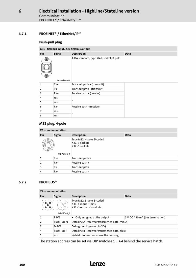
Electrical installation − HighLine/StateLine versionCommunicationPROFINET® / EtherNet/IP�
6
� 100 EDS84DPS424 EN 5.0
6.7.1 PROFINET® / EtherNet/IP�
Push−pull plug
X31 − fieldbus input, X32 fieldbus output
Pin Signal Description Data
AIDA standard, type RJ45, socket, 8−pole
84DWTX0311
1 Tx+ Transmit path + (transmit)
2 Tx− Transmit path − (transmit)
3 Rx+ Receive path + (receive)
4 res.−
5 res.
6 Rx− Receive path − (receive)
7 res.−
8 res.
M12 plug, 4−pole
X3x − communication
Pin Signal Description Data
Type M12, 4−pole, D−codedX31 −> socketsX32 −> sockets
84DPSO05_5
1 Tx+ Transmit path +
2 Rx+ Receive path +
3 Tx− Transmit path −
4 Rx− Receive path −
6.7.2 PROFIBUS®
X3x − communication
Pin Signal Description Data
Type M12, 5−pole, B−codedX31 −> input −> pinsX32 −> output −> sockets
84DPSO05_5
1 P5V2 � Only assigned at the output 5 V DC / 30 mA (bus termination)
2 RxD/TxD−N Data line A (received/transmitted data, minus)
3 M5V2 Data ground (ground to 5 V)
4 RxD/TxD−P Data line B (received/transmitted data, plus)
5 n. c. − (shield connection above the housing)
The station address can be set via DIP switches 1 ... 64 behind the service hatch.
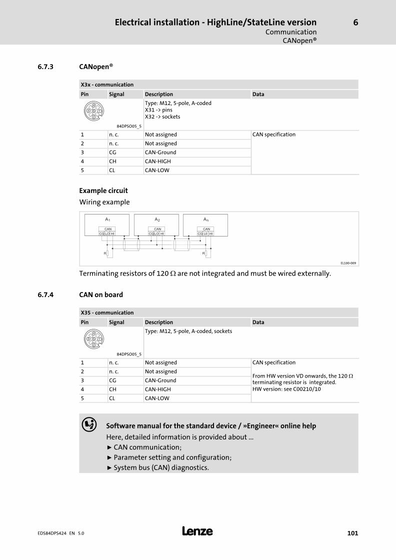
Electrical installation − HighLine/StateLine versionCommunication
CANopen®
6
� 101EDS84DPS424 EN 5.0
6.7.3 CANopen®
X3x − communication
Pin Signal Description Data
Type: M12, 5−pole, A−codedX31 −> pinsX32 −> sockets
84DPSO05_5
1 n. c. Not assigned CAN specification
2 n. c. Not assigned
3 CG CAN−Ground
4 CH CAN−HIGH
5 CL CAN−LOW
Example circuit
Wiring example
CG
CAN
LO HI CG
CAN
LO HI CG
CAN
LO HI
R R
AnA2A1
EL100−009
Terminating resistors of 120 � are not integrated and must be wired externally.
6.7.4 CAN on board
X35 − communication
Pin Signal Description Data
Type: M12, 5−pole, A−coded, sockets
84DPSO05_5
1 n. c. Not assigned CAN specification
From HW version VD onwards, the 120 �terminating resistor is integrated.HW version: see C00210/10
2 n. c. Not assigned
3 CG CAN−Ground
4 CH CAN−HIGH
5 CL CAN−LOW
� Software manual for the standard device / »Engineer« online help
Here, detailed information is provided about ...
ƒ CAN communication;
ƒ Parameter setting and configuration;
ƒ System bus (CAN) diagnostics.
Electrical installation − HighLine/StateLine versionSafety engineering
6
� 102 EDS84DPS424 EN 5.0
6.8 Safety engineering
Please observe the following safety instructions and application notes to preserve thecertified safety engineering features and to ensure trouble−free and safe operation.
� Danger!
Danger to life through improper installation
Improper installation of safety engineering systems can cause an uncontrolledstarting action of the drives.
Possible consequences:
ƒ Death or severe injuries
Protective measures:
ƒ Safety engineering systems may only be installed and commissioned byqualified and skilled personnel.
ƒ All control components (switches, relays, PLC, ...) and the control cabinetmust comply with the requirements of ISO 138491 and ISO 13849−2. Thisincludes i.a.:– Switches, relays with at least IP54 enclosure.– Control cabinet with at least IP54 enclosure.– Please refer to ISO 138491 and ISO 13849−2 for all further requirements.
ƒ Wiring must be shielded.
ƒ All safety relevant cables outside the control cabinet must be protected, e.g.by means of a cable duct:– Ensure that no short circuits can occur.– For further measures see EN ISO 13849−2.
ƒ If an external force acts upon the drive axes, additional brakes are required.Please observe that hanging loads are subject to the force of gravity!
� Danger!
Danger to life by improper installation
Improper installation of the safety equipment may cause an uncontrolled startof the drives.
Possible consequences:
ƒ Death or severe injury
Protective measures:
Shield the cables between the plugs for the safety equipment and theconnected components (e.g. sensors, devices, ...).
� Note!
Please observe during transport, storage and operation:
ƒ Cover unused connectors for control connections and interfaces with theplastic covers provided to preserve the certified safety technology features.
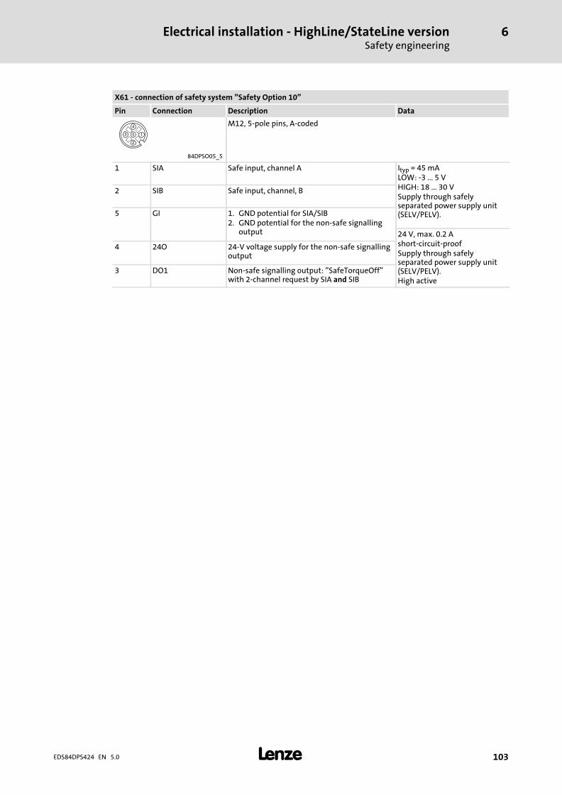
Electrical installation − HighLine/StateLine versionSafety engineering
6
� 103EDS84DPS424 EN 5.0
X61 − connection of safety system "Safety Option 10"
Pin Connection Description Data
M12, 5−pole pins, A−coded
84DPSO05_5
1 SIA Safe input, channel A Ityp = 45 mALOW: −3 ... 5 VHIGH: 18 ... 30 VSupply through safelyseparated power supply unit(SELV/PELV).
2 SIB Safe input, channel, B
5 GI 1. GND potential for SIA/SIB2. GND potential for the non−safe signalling
output 24 V, max. 0.2 Ashort−circuit−proofSupply through safelyseparated power supply unit(SELV/PELV).High active
4 24O 24−V voltage supply for the non−safe signallingoutput
3 DO1 Non−safe signalling output: "SafeTorqueOff"with 2−channel request by SIA and SIB
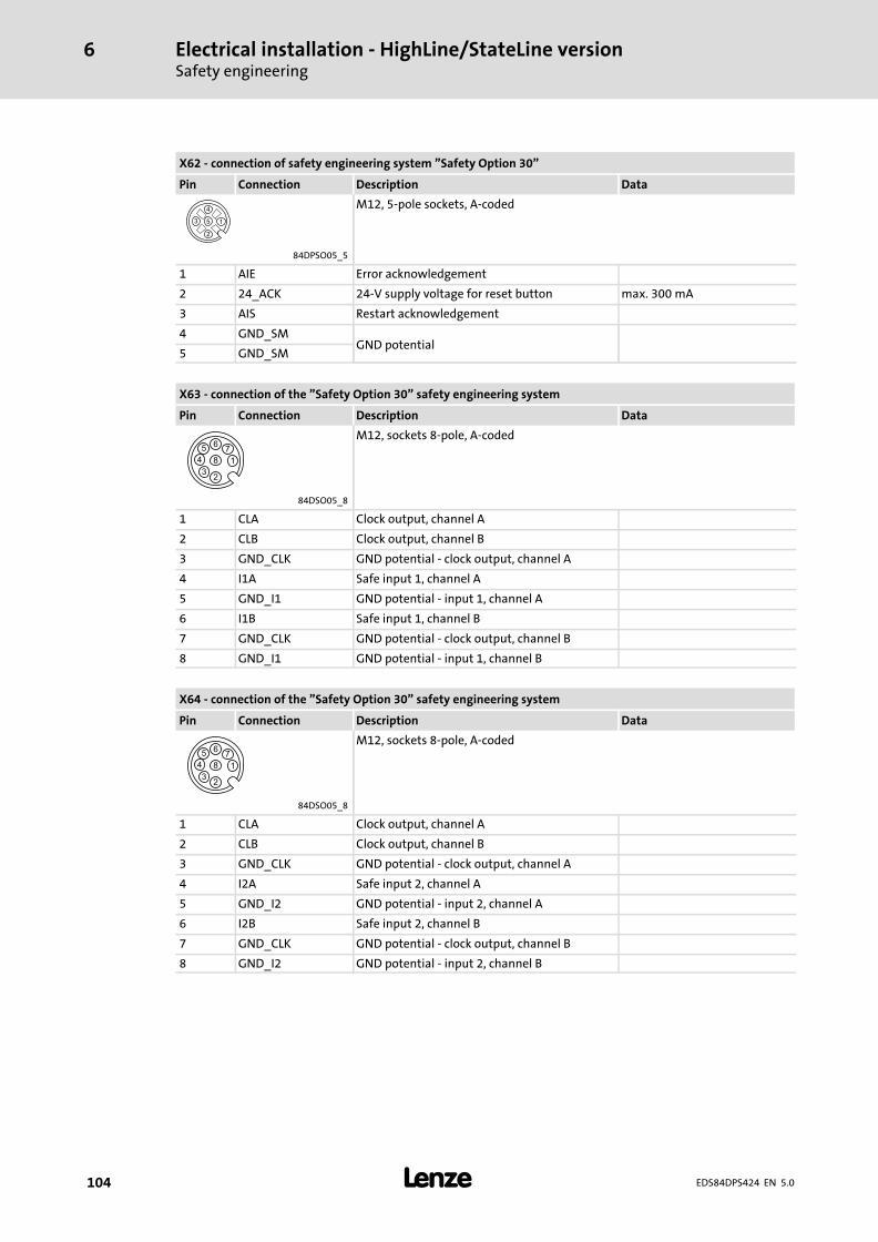
Electrical installation − HighLine/StateLine versionSafety engineering
6
� 104 EDS84DPS424 EN 5.0
X62 − connection of safety engineering system "Safety Option 30"
Pin Connection Description Data
M12, 5−pole sockets, A−coded
84DPSO05_5
1 AIE Error acknowledgement
2 24_ACK 24−V supply voltage for reset button max. 300 mA
3 AIS Restart acknowledgement
4 GND_SMGND potential
5 GND_SM
X63 − connection of the "Safety Option 30" safety engineering system
Pin Connection Description Data
M12, sockets 8−pole, A−coded
84DSO05_8
1 CLA Clock output, channel A
2 CLB Clock output, channel B
3 GND_CLK GND potential − clock output, channel A
4 I1A Safe input 1, channel A
5 GND_I1 GND potential − input 1, channel A
6 I1B Safe input 1, channel B
7 GND_CLK GND potential − clock output, channel B
8 GND_I1 GND potential − input 1, channel B
X64 − connection of the "Safety Option 30" safety engineering system
Pin Connection Description Data
M12, sockets 8−pole, A−coded
84DSO05_8
1 CLA Clock output, channel A
2 CLB Clock output, channel B
3 GND_CLK GND potential − clock output, channel A
4 I2A Safe input 2, channel A
5 GND_I2 GND potential − input 2, channel A
6 I2B Safe input 2, channel B
7 GND_CLK GND potential − clock output, channel B
8 GND_I2 GND potential − input 2, channel B
Electrical installation − EMS versionImportant notes
7
� 105EDS84DPS424 EN 5.0
7 Electrical installation − EMS version
7.1 Important notes
Danger!
Dangerous electrical voltage
All power terminals remain live for up to three minutes after mainsdisconnection.
Possible consequences:
ƒ Death or severe injuries when touching the power terminals.
Protective measures:
ƒ Switch off the power supply and wait for at least three minutes beforeworking on the power terminals.
ƒ Make sure that all power terminals are deenergised.
Danger!
ƒ The contacts of the power connectors X10, X11, X20 and X21 may carrydangerous voltage if the frequency inverter is connected to the mains. Thus,deenergise the frequency inverter before working on it.
ƒ Earth the device by means of X10 and by connecting it to functional earth(earthing bolt) in order to prevent injury to persons and malfunctioning.
Danger!
Dangerous voltage
The leakage current to earth (PE) is > 3.5 mA AC or > 10 mA DC.
Possible consequences:
ƒ Death or severe injuries when the device is touched in the event of a fault.
Protective measures:
ƒ Implement the actions required in the EN 61800−5−1. Especially:– Fixed installation– PE connection must conform to standards (PE conductor diameter� 10 mm2 or PE conductor must be connected twice)
Electrical installation − EMS versionImportant notes
7
� 106 EDS84DPS424 EN 5.0
Stop!
No device protection if the mains voltage is too high
The mains input is not internally fused.
Possible consequences:
ƒ Destruction of the device if the mains voltage is too high.
Protective measures:
ƒ Observe the maximally permissible mains voltage.
ƒ Fuse the device correctly on the supply side against mains fluctuations andvoltage peaks.
Stop!
The device contains components that can be destroyed by electrostaticdischarge!
Before working on the device, the personnel must ensure that they are free ofelectrostatic charge by using appropriate measures.
Stop!
Pluggable terminal strips or plug connections
Plugging or removing the terminal strips or plug connections during operationmay cause high voltages and arcing.
Possible consequences:
ƒ Damage of the devices
Protective measures:
ƒ Switch off device.
ƒ Only plug or remove the terminal strips or plug connections in deenergisedstatus.
� Note!
Switching on the controller motor side is permissible for safety shutdown(emergency stop) and for operation of several motors on the controller in V/foperating mode.
Please observe the following:
ƒ When switching with the controller is enabled, you can activate monitoringfunctions of the controller. If no monitoring function is activated, switchingis permissible.
ƒ The switching elements at the motor end must be rated for DC voltagesVDCmax = 800 V.
Electrical installation − EMS versionImportant notes
7
� 107EDS84DPS424 EN 5.0
� Note!
Only with the control element
ƒ C = service switch with protective function
the device can be disconnected from the mains voltage.
� Note!
The counter plugs of the power terminals must be equipped with connectorhousings with a vertical outgoing cable.
� Note!
ƒ It is absolutely necessary to keep the plastic caps on the connectors for thecontrol terminals and interfaces!
ƒ During transport, storage, and operation, ports not used must be sealedusing the plastic caps, in order to maintain the product features inaccordance with the technical data.
ƒ Only if this note is observed, the product features certified are ensured fordevices with a safety system.
EMC−compliant wiring
� Note!
ƒ Establish a good conductive connection to protective earth by means of acopper−braid cable (e.g. mounting surface, machine earth or building earth).
ƒ Lay control cables and data lines separately from the motor cables.
ƒ Connect the shields of the control cables and data lines at both ends.
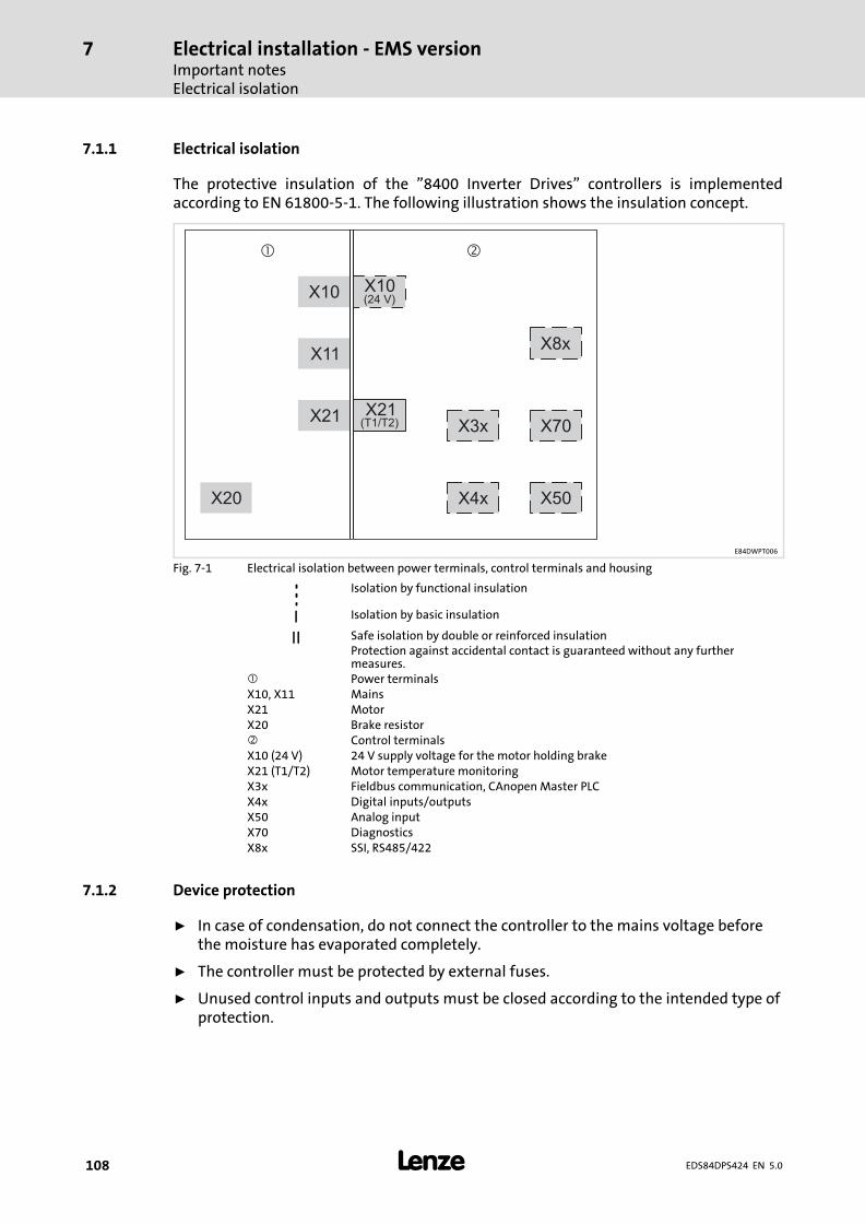
Electrical installation − EMS versionImportant notesElectrical isolation
7
� 108 EDS84DPS424 EN 5.0
7.1.1 Electrical isolation
The protective insulation of the "8400 Inverter Drives" controllers is implementedaccording to EN 61800−5−1. The following illustration shows the insulation concept.
X10
X11
X20
X21 X21X3x
X4x
X70
X8x
X10(24 V)
(T1/T2)
� �
X50
E84DWPT006
Fig. 7−1 Electrical isolation between power terminals, control terminals and housing
Isolation by functional insulation
I Isolation by basic insulation
II Safe isolation by double or reinforced insulationProtection against accidental contact is guaranteed without any furthermeasures.
� Power terminalsX10, X11 MainsX21 MotorX20 Brake resistor� Control terminalsX10 (24 V) 24 V supply voltage for the motor holding brakeX21 (T1/T2) Motor temperature monitoringX3x Fieldbus communication, CAnopen Master PLCX4x Digital inputs/outputsX50 Analog inputX70 DiagnosticsX8x SSI, RS485/422
7.1.2 Device protection
ƒ In case of condensation, do not connect the controller to the mains voltage beforethe moisture has evaporated completely.
ƒ The controller must be protected by external fuses.
ƒ Unused control inputs and outputs must be closed according to the intended type ofprotection.
Electrical installation − EMS versionImportant notes
Maximum motor cable length
7
� 109EDS84DPS424 EN 5.0
7.1.3 Maximum motor cable length
ƒ Keep the motor cable as short as possible since this has a positive effect on the drivebehaviour.
ƒ The maximally permissible motor cable length is: 20 m, shielded
– at rated mains voltage
– at a switching frequency of 8 kHz
� Note!
If the conditions for electromagnetic compatibility must be observed, thepermissible cable lengths may vary.
7.1.4 Motor protection
ƒ Extensive protection against overload:
– By overcurrent relays or temperature monitoring.
– We recommend the use of PTC thermistors or thermostats to monitor the motortemperature.
– PTC thermistors or thermostats can be connected to the controller.
– For monitoring the motor, we recommend the use of the I2xt monitoring.
ƒ Only use motors with an insulation suitable for the inverter operation:
– Insulation resistance: min. û = 1.5 kV, min. du/dt = 5 kV/�s
– When using motors with an unknown insulation resistance, please contact yourmotor supplier.
Electrical installation − EMS versionSafety instructions for the installation according to UL or UR
7
� 110 EDS84DPS424 EN 5.0
7.2 Safety instructions for the installation according to UL or UR
Original − English
� Warnings!
ƒ Branch circuit protection:
Suitable for use on a circuit capable of delivering not more than 200 000 rmssymmetrical amperes, 500 V maximum.– When Protected by CC, T, or J Class Fuses.
ƒ Integral solid state protection does not provide branch circuit protection.Branch circuit protection must be provided in accordance with the NationalElectrical Code and any additional local codes.
ƒ Overload Protection = 125 % of rated FLA.
ƒ Use 75 °C copper wire only, except for control circuits.
ƒ Use Class 1 wire only.
ƒ Enclosed Device, suitable for use in a UL Type 4X (Indoor) Environment.
ƒ Suitable for use in a surrounding air temperature of 45 °C, and– additionally 55 °C when de−rating rules are followed.
ƒ Suitable for use in a compartment handling conditioned air.
ƒ The device is provided with internal overload protection. For information onthe protection level of the internal overload protection for a motor load, seethe corresponding Software Manual or Online Help under the topic "Motorload monitoring (I2xt)". This function has to be activated; i. e. the reactionmust be changed from "Warning" (factory setting) to "Fault".
ƒ For information on rating and proper connection of the thermal protector(only for connection to motors having integral thermal protection), see thecorresponding Manual or Online Help.
� Warnings!
The opening of branch−circuit protective device may be an indication that afault has been interrupted.
To reduce the risk of fire or electric shock, current−carrying parts and othercomponents of the controller should be examined and replaced if damaged orequivalent.
Electrical installation − EMS versionSafety instructions for the installation according to UL or UR
7
� 111EDS84DPS424 EN 5.0
7.3 Safety instructions for the installation according to UL or UR
Original − French
� Avertissement !
ƒ Protection par disjoncteur :
Convient aux circuits non susceptibles de délivrer plus de 200 000 ampèressymétriques eff., maximum 500 V.– Protection par des fusibles CC de calibre T ou J.
ƒ La protection statique intégrée n’offre pas la même protection qu’undisjoncteur. Une protection par disjoncteur externe doit être fournie,conformément au National Electrical Code et aux autres dispositionsapplicables au niveau local.
ƒ Protection contre les surcharges = 125 % de l’intensité assignée à pleinecharge.
ƒ Utiliser exclusivement des conducteurs en cuivre 75 °C, sauf pour la partiecommande.
ƒ Utiliser impérativement un câble de classe 1.
ƒ Equipement monté dans un coffret de protection adapté à une utilisation enenvironnement UL de type 4X (intérieur).
ƒ Convient à une utilisation à une température ambiante maximale de 45 °Cainsi que– 55 °C en cas d’application des règles de réduction de puissance.
ƒ Convient pour une utilisation dans un a espace à air conditionné.
ƒ L’équipement est doté d’un dispositif de protection intégré contre lessurcharges. Pour obtenir des informations sur le niveau de protection offertpar la protection intégrée contre les surcharges du moteur, se reporter aumanuel du logiciel ou à l’aide en ligne correspondante, rubrique"Surveillance de la charge du moteur (I2xt)". Cette fonction doit être activée.En d’autres termes, la réaction doit être modifiée de "Avertissement"(réglage usine) à "Défaut".
ƒ Pour obtenir des informations sur les caractéristiques assignées et sur leraccordement correct du dispositif de protection thermique (uniquementpour raccordement à des moteurs dotés d’une protection thermiqueintégrée), se reporter au manuel correspondant ou à l’aide en ligne.
� Avertissement !
Le déclenchement du dispositif de protection du circuit de dérivation peut êtredû à une coupure qui résulte d’un courant de défaut.
Pour limiter le risque d’incendie ou de choc électrique, examiner les piècesporteuses de courant et les autres éléments du contrôleur et les remplacer s’ilssont endommagés.
Electrical installation − EMS versionInstallation according to EMC (installation of a CE−typical drive system)Shielding
7
� 112 EDS84DPS424 EN 5.0
7.4 Installation according to EMC (installation of a CE−typical drive system)
Design of the cables
ƒ It is imperative to comply with the regulations concerning minimum cross−sectionsof PE conductors. The cross−section of the PE conductor must be at least as large asthe cross−section of the power connections.
ƒ The cables used must comply with the approvals required for the location (e.g. UL).
7.4.1 Shielding
Requirements
ƒ The effectiveness of a shielded cable is reached by:
– Providing a good shield connection through large−surface shield contact.
– Using only braided shields with low shield resistance made of tin−plated ornickel−plated copper braid.
– Using braided shields with an overlap rate > 70 % and an overlap angle of 90 °.
– Keeping unshielded cable ends as short as possible.
Use system cables or shielded cables for these connections:
ƒ Motor
ƒ External brake resistor (� Mounting Instructions of the brake resistor)
ƒ Motor holding brake (shielding is required when being integrated into the motorcable; connection to optional motor brake control)
ƒ Motor temperature monitoring
ƒ Fieldbus communication (e.g. CANopen)
ƒ Serial interfaces (e.g. SSI, RS485/422)
The following connections need not be shielded:
ƒ Mains
ƒ 24 V supply for motor holding brakes
ƒ Digital signals (inputs and outputs). From a cable length of approx. 5 m onwards, werecommend to use shielded cables.
Connection system
ƒ Directly apply the shielding in the plug.
– Extensively apply the shielding and ensure electrical conductivity.
– If required, additionally connect the shield to the cable clamp rail.
Electrical installation − EMS versionInstallation according to EMC (installation of a CE−typical drive system)
Motor cable
7
� 113EDS84DPS424 EN 5.0
7.4.2 Motor cable
ƒ Only use shielded motor cables with braids made of tinned or nickel−plated copper.Shields made of steel braids are not suitable.
– The overlap rate of the braid must be at least 70 % with an overlap angle of 90 °.
ƒ The cables used must correspond to the requirements at the location (e.g.EN 60204−1).
ƒ Use Lenze system cables.
ƒ Extensively apply the shielding in the plug and attach it in a way which ensureselectrical conductivity.
ƒ The motor cable is optimally installed if
– it is separated from mains cables and control cables,
– it only crosses mains cables and control cables at right angles,
– it is not interrupted.
ƒ If the motor cable must be opened all the same (e.g. due to chokes, contactors, orterminals):
– The unshielded cable ends may not be longer than 100 mm (depending on thecable cross−section).
– Install chokes, contactors, terminals etc. spatially separated from othercomponents (with a min. distance of 100 mm).
– Install the shield of the motor cable directly before and behind the point ofseparation to the mounting plate with a large surface.
ƒ Connect the shield with a large surface to PE in the terminal box of the motor at themotor housing.
– Metal EMC cable glands at the motor terminal box ensure a large surfaceconnection of the shield with the motor housing.
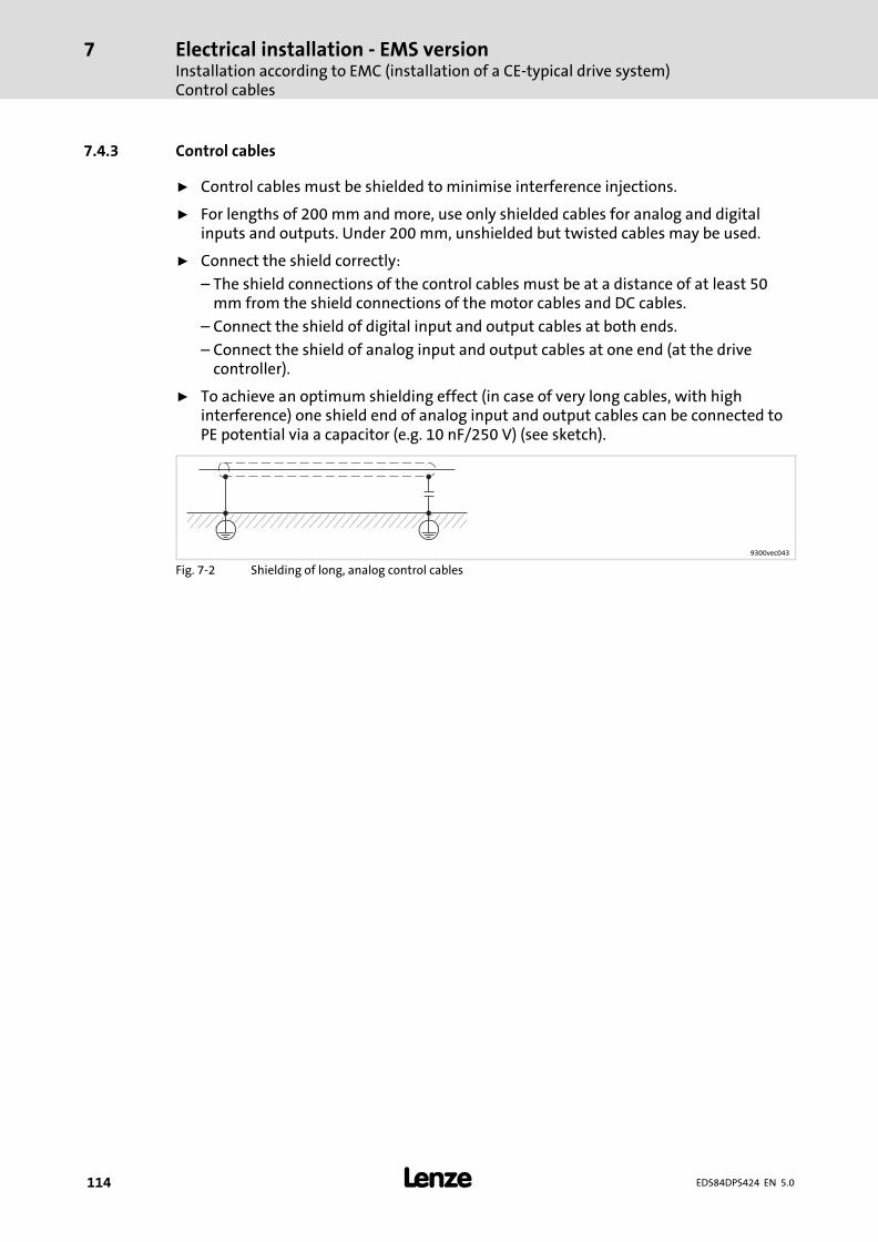
Electrical installation − EMS versionInstallation according to EMC (installation of a CE−typical drive system)Control cables
7
� 114 EDS84DPS424 EN 5.0
7.4.3 Control cables
ƒ Control cables must be shielded to minimise interference injections.
ƒ For lengths of 200 mm and more, use only shielded cables for analog and digitalinputs and outputs. Under 200 mm, unshielded but twisted cables may be used.
ƒ Connect the shield correctly:
– The shield connections of the control cables must be at a distance of at least 50mm from the shield connections of the motor cables and DC cables.
– Connect the shield of digital input and output cables at both ends.
– Connect the shield of analog input and output cables at one end (at the drivecontroller).
ƒ To achieve an optimum shielding effect (in case of very long cables, with highinterference) one shield end of analog input and output cables can be connected toPE potential via a capacitor (e.g. 10 nF/250 V) (see sketch).
9300vec043
Fig. 7−2 Shielding of long, analog control cables
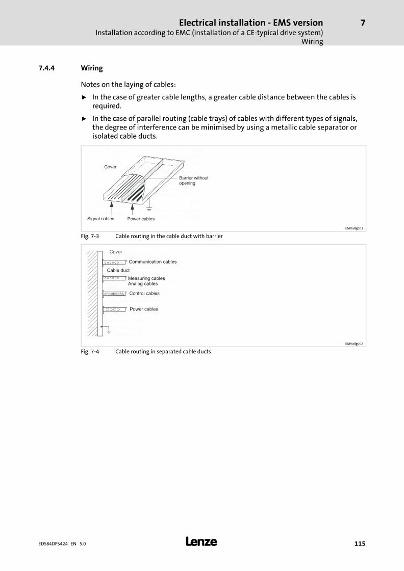
Electrical installation − EMS versionInstallation according to EMC (installation of a CE−typical drive system)
Wiring
7
� 115EDS84DPS424 EN 5.0
7.4.4 Wiring
Notes on the laying of cables:
ƒ In the case of greater cable lengths, a greater cable distance between the cables isrequired.
ƒ In the case of parallel routing (cable trays) of cables with different types of signals,the degree of interference can be minimised by using a metallic cable separator orisolated cable ducts.
Cover
Barrier withoutopening
Power cablesSignal cables
EMVallg001
Fig. 7−3 Cable routing in the cable duct with barrier
Cover
Communication cables
Cable duct
Measuring cablesAnalog cables
Control cables
Power cables
EMVallg002
Fig. 7−4 Cable routing in separated cable ducts
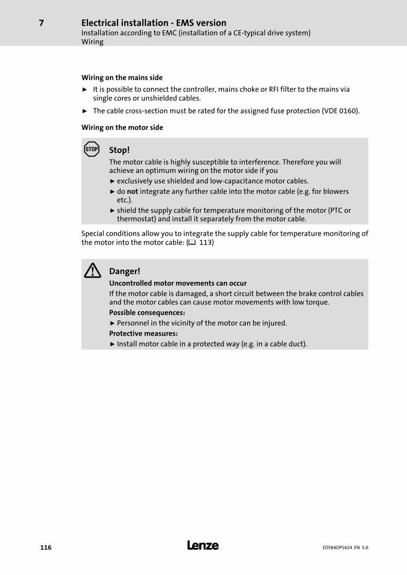
Electrical installation − EMS versionInstallation according to EMC (installation of a CE−typical drive system)Wiring
7
� 116 EDS84DPS424 EN 5.0
Wiring on the mains side
ƒ It is possible to connect the controller, mains choke or RFI filter to the mains viasingle cores or unshielded cables.
ƒ The cable cross−section must be rated for the assigned fuse protection (VDE 0160).
Wiring on the motor side
Stop!
The motor cable is highly susceptible to interference. Therefore you willachieve an optimum wiring on the motor side if you
ƒ exclusively use shielded and low−capacitance motor cables.
ƒ do not integrate any further cable into the motor cable (e.g. for blowersetc.).
ƒ shield the supply cable for temperature monitoring of the motor (PTC orthermostat) and install it separately from the motor cable.
Special conditions allow you to integrate the supply cable for temperature monitoring ofthe motor into the motor cable: (� 113)
� Danger!
Uncontrolled motor movements can occur
If the motor cable is damaged, a short circuit between the brake control cablesand the motor cables can cause motor movements with low torque.
Possible consequences:
ƒ Personnel in the vicinity of the motor can be injured.
Protective measures:
ƒ Install motor cable in a protected way (e.g. in a cable duct).
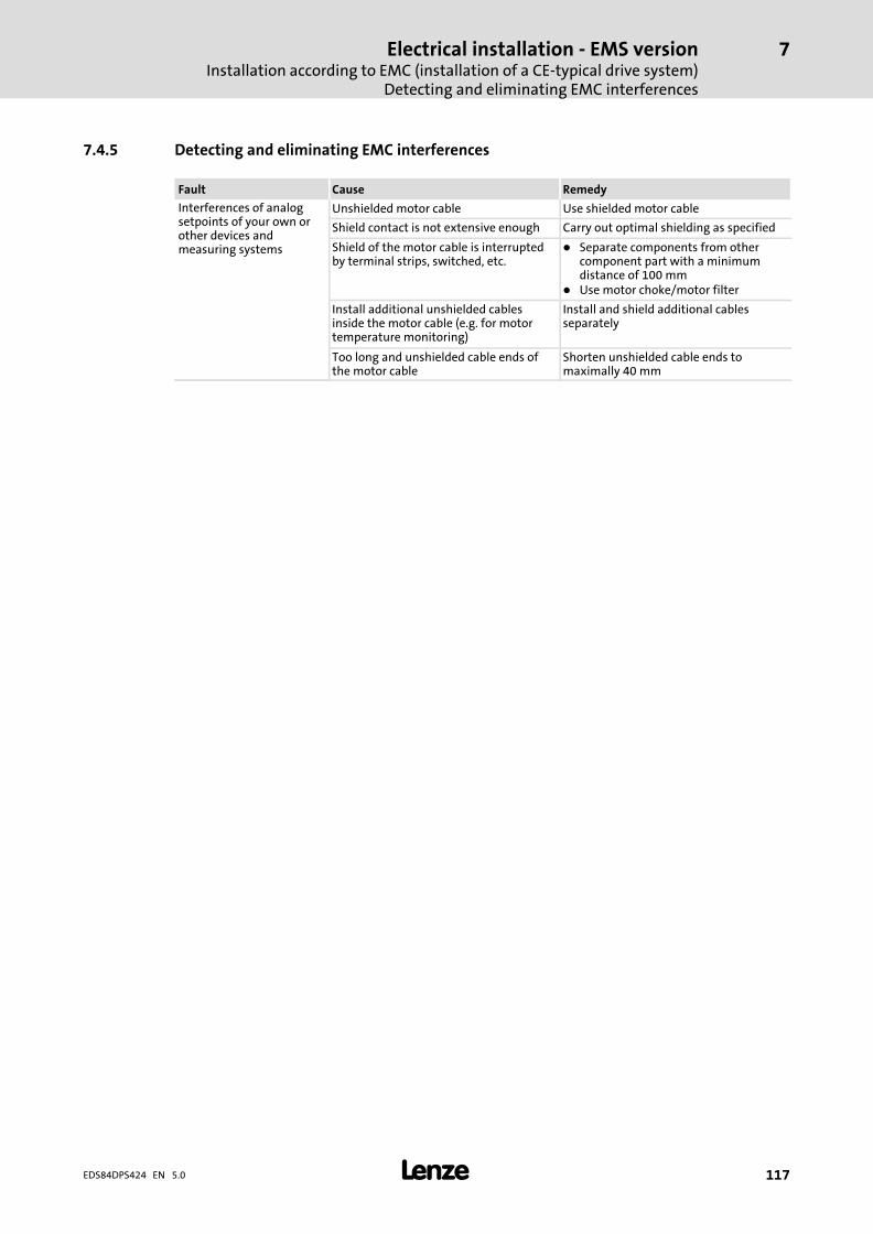
Electrical installation − EMS versionInstallation according to EMC (installation of a CE−typical drive system)
Detecting and eliminating EMC interferences
7
� 117EDS84DPS424 EN 5.0
7.4.5 Detecting and eliminating EMC interferences
Fault Cause Remedy
Interferences of analogsetpoints of your own orother devices andmeasuring systems
Unshielded motor cable Use shielded motor cable
Shield contact is not extensive enough Carry out optimal shielding as specified
Shield of the motor cable is interruptedby terminal strips, switched, etc.
� Separate components from othercomponent part with a minimumdistance of 100 mm
� Use motor choke/motor filter
Install additional unshielded cablesinside the motor cable (e.g. for motortemperature monitoring)
Install and shield additional cablesseparately
Too long and unshielded cable ends ofthe motor cable
Shorten unshielded cable ends tomaximally 40 mm
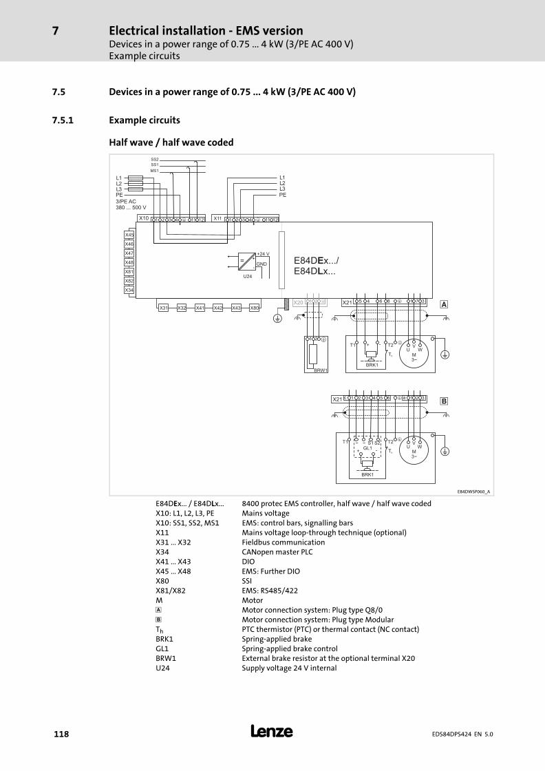
Electrical installation − EMS versionDevices in a power range of 0.75 ... 4 kW (3/PE AC 400 V)Example circuits
7
� 118 EDS84DPS424 EN 5.0
7.5 Devices in a power range of 0.75 ... 4 kW (3/PE AC 400 V)
7.5.1 Example circuits
Half wave / half wave coded
M3~
UV
W
�
�BRK1
T1 T2
Th
+ -
��
�
��
64 1 2 3X21 �c 1 2 3 a5
M3~
UV
W
�
�T1 T2
Th
BRK1
+ -
~ ~ S1 S2GL1
�
E84Dx...
5 84 6 1 7 3X21 �1 2X20 �
X80X43X42X41X32X31
�
1 112 3 4 12�X10 1 112 3 4 12�X11
+
-
+24 V
GND
U24
=
X46
X47
X48
X45
X81
X82
X34
BRW1
1 2 �
�
E84D x.../E84D x...
EL
3/PE AC380 ... 500 V
L1L2L3PE
L1L2L3PE
MS1
SS1
SS2
E84DWSP060_A
E84DEx... / E84DLx... 8400 protec EMS controller, half wave / half wave codedX10: L1, L2, L3, PE Mains voltageX10: SS1, SS2, MS1 EMS: control bars, signalling barsX11 Mains voltage loop−through technique (optional)X31 ... X32 Fieldbus communicationX34 CANopen master PLCX41 ... X43 DIOX45 ... X48 EMS: Further DIOX80 SSIX81/X82 EMS: RS485/422M Motor� Motor connection system: Plug type Q8/0 Motor connection system: Plug type ModularTh PTC thermistor (PTC) or thermal contact (NC contact)BRK1 Spring−applied brakeGL1 Spring−applied brake controlBRW1 External brake resistor at the optional terminal X20U24 Supply voltage 24 V internal
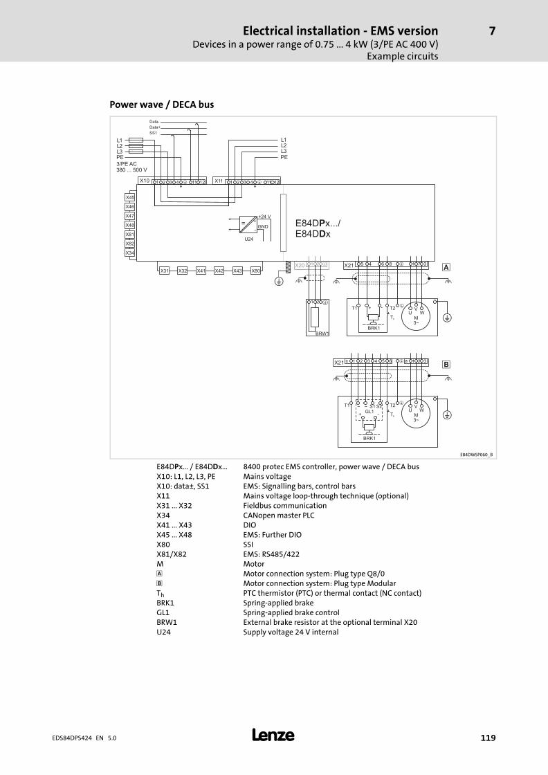
Electrical installation − EMS versionDevices in a power range of 0.75 ... 4 kW (3/PE AC 400 V)
Example circuits
7
� 119EDS84DPS424 EN 5.0
Power wave / DECA bus
M3~
UV
W
�
�BRK1
T1 T2
Th
+ -
��
�
��
64 1 2 3X21 �c 1 2 3 a5
M3~
UV
W
�
�T1 T2
Th
BRK1
+ -
~ ~ S1 S2GL1
�
E84Dx...
5 84 6 1 7 3X21 �1 2X20 �
X80X43X42X41X32X31
�
1 112 3 4 12�X10 1 112 3 4 12�X11
+
-
+24 V
GND
U24
=
X46
X47
X48
X45
X81
X82
X34
BRW1
1 2 �
�
E84D x.../E84D x
PD
3/PE AC380 ... 500 V
L1L2L3PE
L1L2L3PE
Data+
SS1
Data-
E84DWSP060_B
E84DPx... / E84DDx... 8400 protec EMS controller, power wave / DECA busX10: L1, L2, L3, PE Mains voltageX10: data±, SS1 EMS: Signalling bars, control barsX11 Mains voltage loop−through technique (optional)X31 ... X32 Fieldbus communicationX34 CANopen master PLCX41 ... X43 DIOX45 ... X48 EMS: Further DIOX80 SSIX81/X82 EMS: RS485/422M Motor� Motor connection system: Plug type Q8/0 Motor connection system: Plug type ModularTh PTC thermistor (PTC) or thermal contact (NC contact)BRK1 Spring−applied brakeGL1 Spring−applied brake controlBRW1 External brake resistor at the optional terminal X20U24 Supply voltage 24 V internal
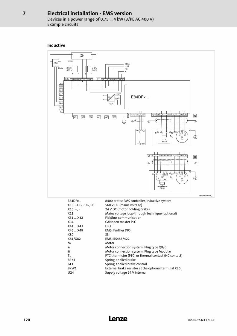
Electrical installation − EMS versionDevices in a power range of 0.75 ... 4 kW (3/PE AC 400 V)Example circuits
7
� 120 EDS84DPS424 EN 5.0
Inductive
M3~
UV
W
�
�BRK1
T1 T2
Th
+ -
��
�
��
64 1 2 3X21 �c 1 2 3 a5
M3~
UV
W
�
�T1 T2
Th
BRK1
+ -
~ ~ S1 S2GL1
�
E84Dx...
5 84 6 1 7 3X21 �1 2X20 �
X80X43X42X41X32X31
�
1 112 3 4 12�X10 1 112 3 4 12�X11
+
-
+24 V
GND
U24
=
X46
X47
X48
X45
X81
X82
X34
BRW1
1 2 �
�
E84D x...F
2 DC560 V
+ -
+UG-UGPE
+ -
2 DC24 V
+-
Power
Data
E84DWSP060_D
E84DFx... 8400 protec EMS controller, inductive systemX10: +UG, −UG, PE 560 V DC (mains voltage)X10: +, − 24 V DC (motor holding brake)X11 Mains voltage loop−through technique (optional)X31 ... X32 Fieldbus communicationX34 CANopen master PLCX41 ... X43 DIOX45 ... X48 EMS: Further DIOX80 SSIX81/X82 EMS: RS485/422M Motor� Motor connection system: Plug type Q8/0 Motor connection system: Plug type ModularTh PTC thermistor (PTC) or thermal contact (NC contact)BRK1 Spring−applied brakeGL1 Spring−applied brake controlBRW1 External brake resistor at the optional terminal X20U24 Supply voltage 24 V internal
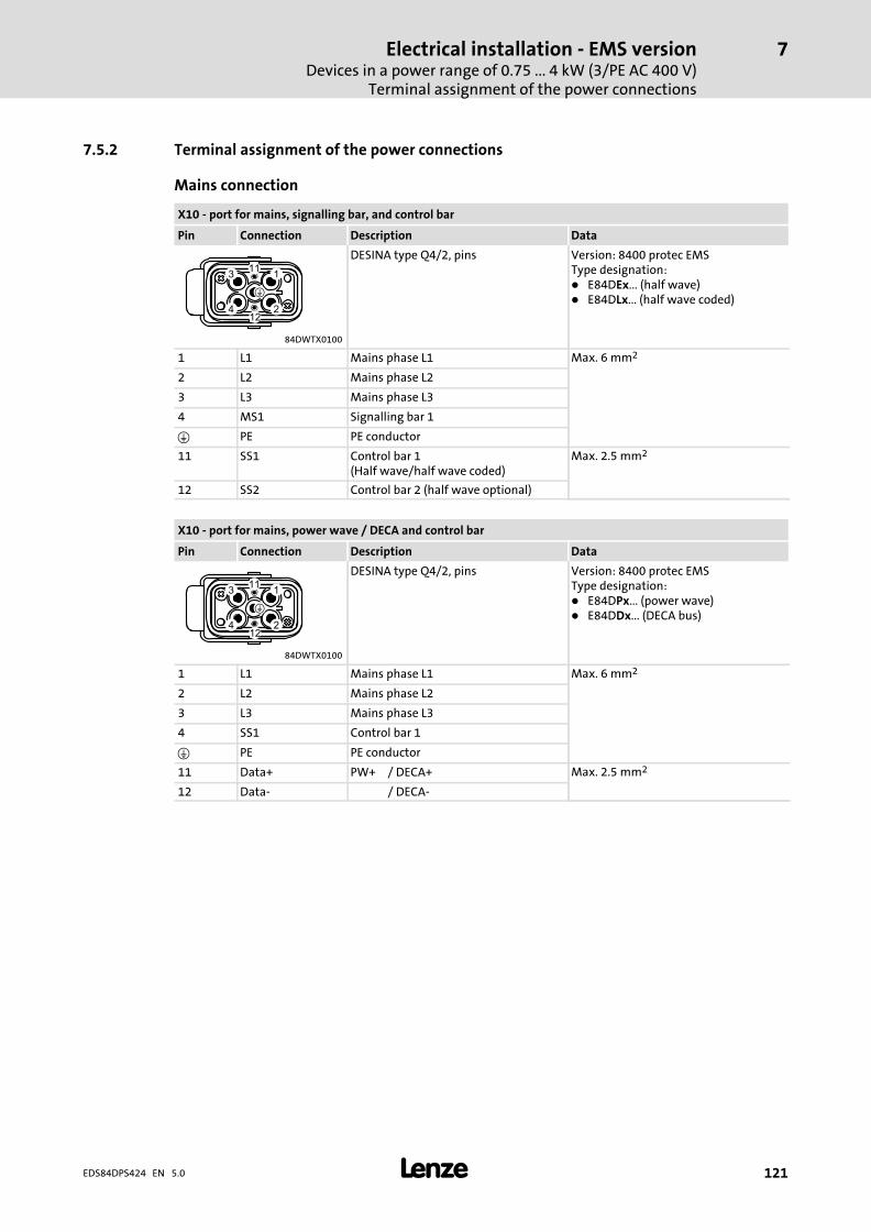
Electrical installation − EMS versionDevices in a power range of 0.75 ... 4 kW (3/PE AC 400 V)
Terminal assignment of the power connections
7
� 121EDS84DPS424 EN 5.0
7.5.2 Terminal assignment of the power connections
Mains connection
X10 − port for mains, signalling bar, and control bar
Pin Connection Description Data
DESINA type Q4/2, pins Version: 8400 protec EMSType designation:� E84DEx... (half wave)� E84DLx... (half wave coded)
84DWTX0100
1 L1 Mains phase L1 Max. 6 mm2
2 L2 Mains phase L2
3 L3 Mains phase L3
4 MS1 Signalling bar 1
� PE PE conductor
11 SS1 Control bar 1(Half wave/half wave coded)
Max. 2.5 mm2
12 SS2 Control bar 2 (half wave optional)
X10 − port for mains, power wave / DECA and control bar
Pin Connection Description Data
DESINA type Q4/2, pins Version: 8400 protec EMSType designation:� E84DPx... (power wave)� E84DDx... (DECA bus)
84DWTX0100
1 L1 Mains phase L1 Max. 6 mm2
2 L2 Mains phase L2
3 L3 Mains phase L3
4 SS1 Control bar 1
� PE PE conductor
11 Data+ PW+ / DECA+ Max. 2.5 mm2
12 Data− / DECA−
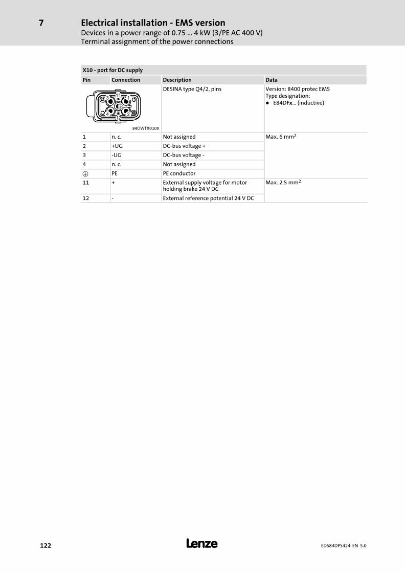
Electrical installation − EMS versionDevices in a power range of 0.75 ... 4 kW (3/PE AC 400 V)Terminal assignment of the power connections
7
� 122 EDS84DPS424 EN 5.0
X10 − port for DC supply
Pin Connection Description Data
DESINA type Q4/2, pins Version: 8400 protec EMSType designation:� E84DFx... (inductive)
84DWTX0100
1 n. c. Not assigned Max. 6 mm2
2 +UG DC−bus voltage +
3 −UG DC−bus voltage −
4 n. c. Not assigned
� PE PE conductor
11 + External supply voltage for motorholding brake 24 V DC
Max. 2.5 mm2
12 − External reference potential 24 V DC
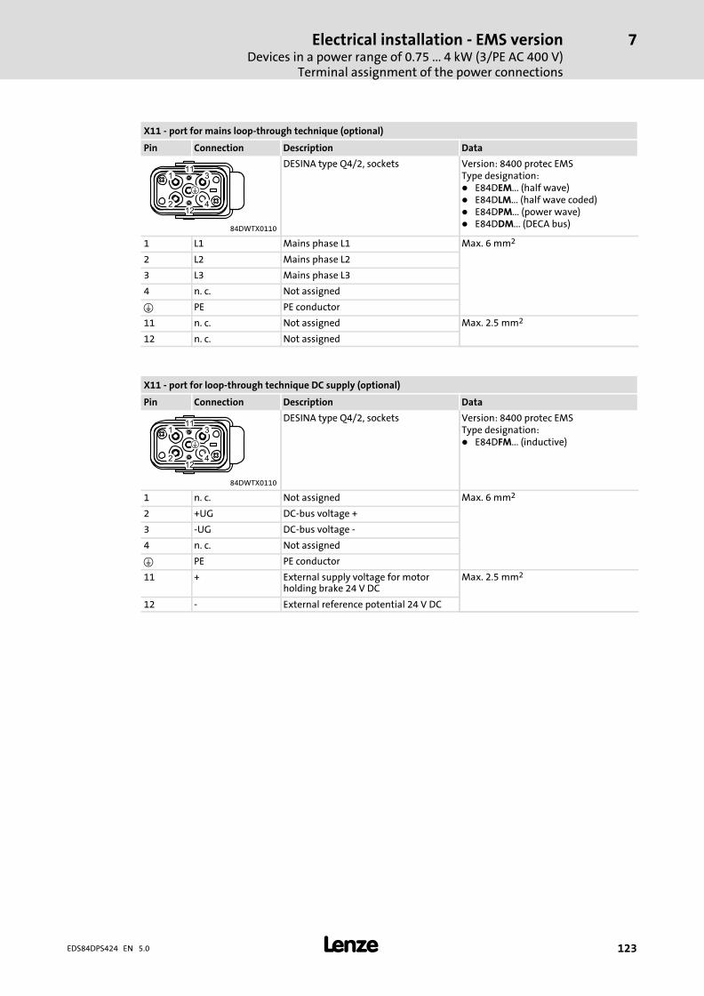
Electrical installation − EMS versionDevices in a power range of 0.75 ... 4 kW (3/PE AC 400 V)
Terminal assignment of the power connections
7
� 123EDS84DPS424 EN 5.0
X11 − port for mains loop−through technique (optional)
Pin Connection Description Data
DESINA type Q4/2, sockets Version: 8400 protec EMSType designation:� E84DEM... (half wave)� E84DLM... (half wave coded)� E84DPM... (power wave)� E84DDM... (DECA bus)
84DWTX0110
1 L1 Mains phase L1 Max. 6 mm2
2 L2 Mains phase L2
3 L3 Mains phase L3
4 n. c. Not assigned
� PE PE conductor
11 n. c. Not assigned Max. 2.5 mm2
12 n. c. Not assigned
X11 − port for loop−through technique DC supply (optional)
Pin Connection Description Data
DESINA type Q4/2, sockets Version: 8400 protec EMSType designation:� E84DFM... (inductive)
84DWTX0110
1 n. c. Not assigned Max. 6 mm2
2 +UG DC−bus voltage +
3 −UG DC−bus voltage −
4 n. c. Not assigned
� PE PE conductor
11 + External supply voltage for motorholding brake 24 V DC
Max. 2.5 mm2
12 − External reference potential 24 V DC
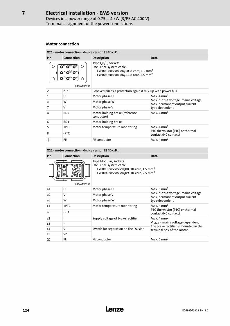
Electrical installation − EMS versionDevices in a power range of 0.75 ... 4 kW (3/PE AC 400 V)Terminal assignment of the power connections
7
� 124 EDS84DPS424 EN 5.0
Motor connection
X21 − motor connection − device version E84DxxC...
Pin Connection Description Data
12
3
45
67
8
�
Type Q8/0, socketsUse Lenze system cable:
EYP0037xxxxxxxxQ10, 8−core, 1.5 mm2
EYP0038xxxxxxxxQ11, 8 core, 2.5 mm2
84DWTX0210
2 n. c. Grooved pin as a protection against mix−up with power bus
1 U Motor phase U Max. 4 mm2
Max. output voltage: mains voltageMax. permanent output current:type−dependent
3 W Motor phase W
7 V Motor phase V
4 BD2 Motor holding brake (referenceconductor)
Max. 4 mm2
6 BD1 Motor holding brake
5 +PTC Motor temperature monitoring Max. 4 mm2
PTC thermistor (PTC) or thermalcontact (NC contact)8 −PTC
� PE PE conductor Max. 4 mm2
X21 − motor connection − device version E84DxxB...
Pin Connection Description Data
Type Modular, socketsUse Lenze system cable:
EYP0039xxxxxxxxQ08, 10−core, 1.5 mm2
EYP0040xxxxxxxxQ09, 10−core, 2.5 mm2
84DWTX0211
a1 U Motor phase U Max. 6 mm2
Max. output voltage: mains voltageMax. permanent output current:type−dependent
a2 V Motor phase V
a3 W Motor phase W
c1 +PTC Motor temperature monitoring Max. 4 mm2
PTC thermistor (PTC) or thermalcontact (NC contact)c6 −PTC
c2 ~ Supply voltage of brake rectifier Max. 4 mm2
Vrated = mains voltage−dependentThe brake rectifier is mounted in theterminal box of the motor.
c3 ~
c4 S1 Switch for separation on the DC side
c5 S2
� PE PE conductor Max. 6 mm2
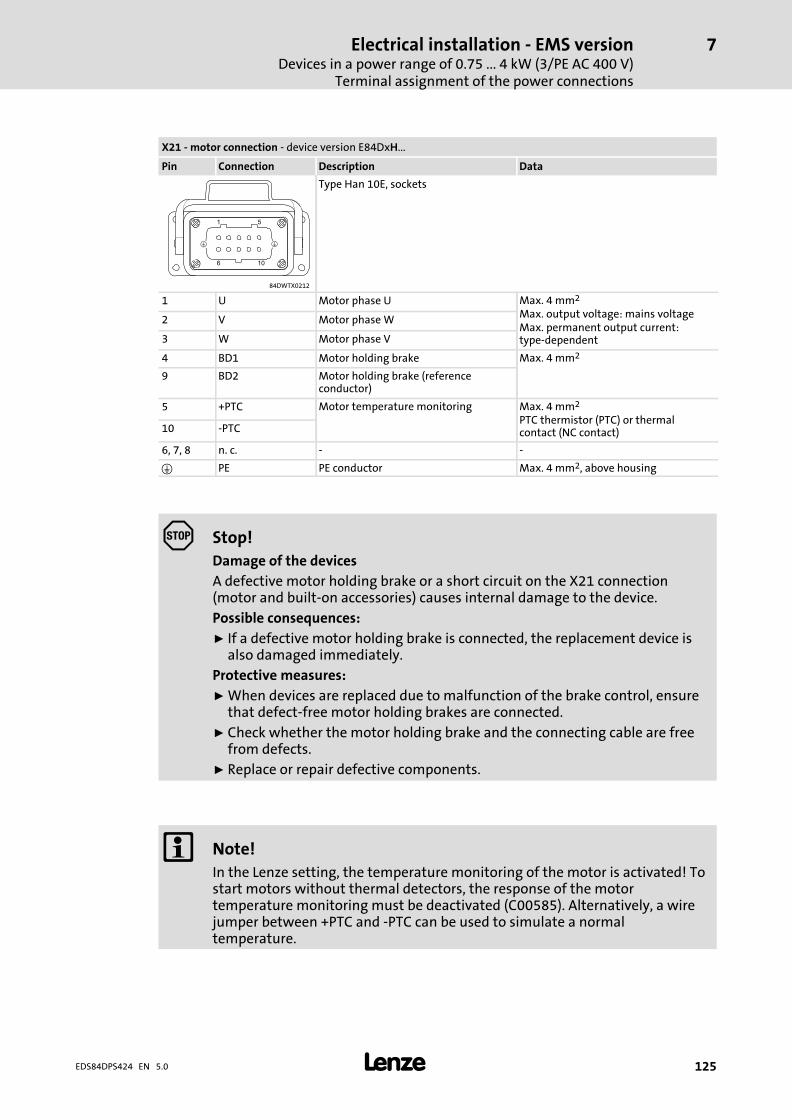
Electrical installation − EMS versionDevices in a power range of 0.75 ... 4 kW (3/PE AC 400 V)
Terminal assignment of the power connections
7
� 125EDS84DPS424 EN 5.0
X21 − motor connection − device version E84DxH...
Pin Connection Description Data
Type Han 10E, sockets
84DWTX0212
1 U Motor phase U Max. 4 mm2
Max. output voltage: mains voltageMax. permanent output current:type−dependent
2 V Motor phase W
3 W Motor phase V
4 BD1 Motor holding brake Max. 4 mm2
9 BD2 Motor holding brake (referenceconductor)
5 +PTC Motor temperature monitoring Max. 4 mm2
PTC thermistor (PTC) or thermalcontact (NC contact)10 −PTC
6, 7, 8 n. c. − −
� PE PE conductor Max. 4 mm2, above housing
Stop!
Damage of the devices
A defective motor holding brake or a short circuit on the X21 connection(motor and built−on accessories) causes internal damage to the device.
Possible consequences:
ƒ If a defective motor holding brake is connected, the replacement device isalso damaged immediately.
Protective measures:
ƒ When devices are replaced due to malfunction of the brake control, ensurethat defect−free motor holding brakes are connected.
ƒ Check whether the motor holding brake and the connecting cable are freefrom defects.
ƒ Replace or repair defective components.
� Note!
In the Lenze setting, the temperature monitoring of the motor is activated! Tostart motors without thermal detectors, the response of the motortemperature monitoring must be deactivated (C00585). Alternatively, a wirejumper between +PTC and −PTC can be used to simulate a normaltemperature.
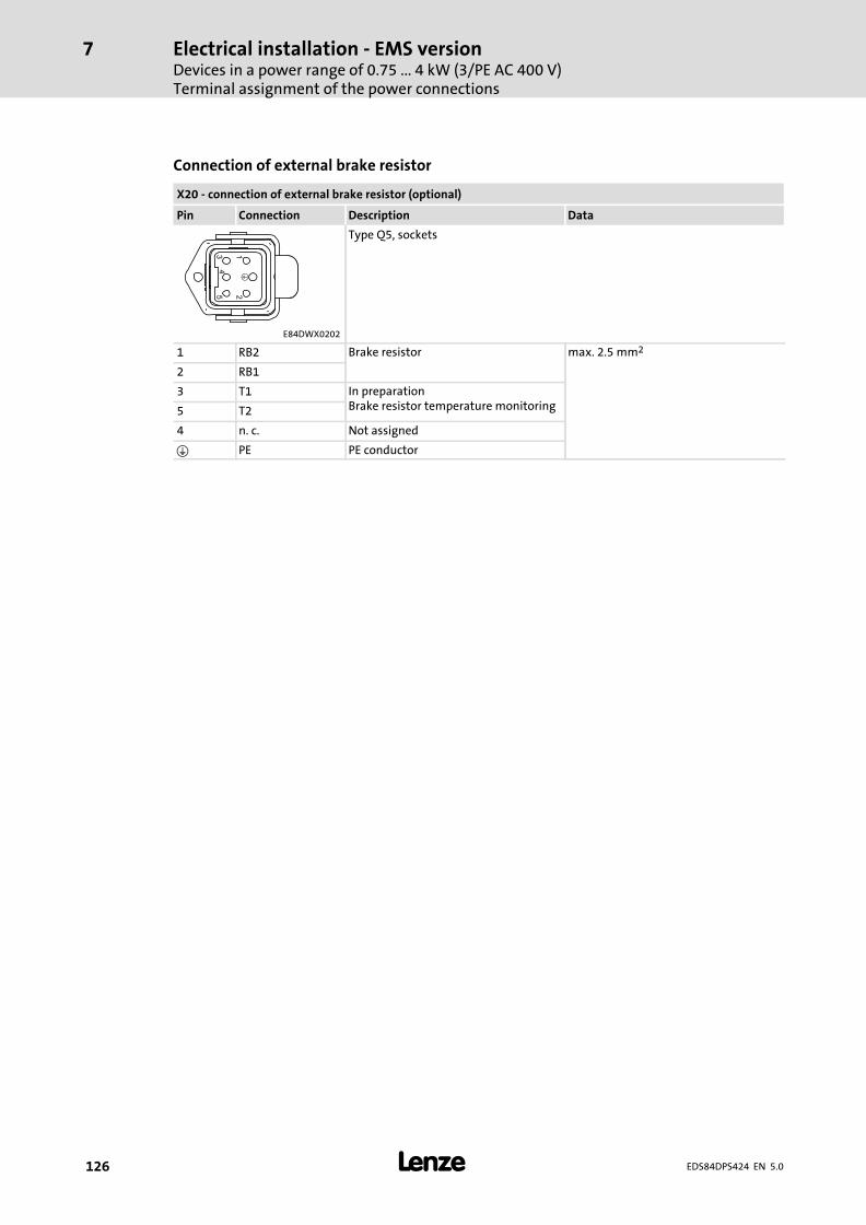
Electrical installation − EMS versionDevices in a power range of 0.75 ... 4 kW (3/PE AC 400 V)Terminal assignment of the power connections
7
� 126 EDS84DPS424 EN 5.0
Connection of external brake resistor
X20 − connection of external brake resistor (optional)
Pin Connection Description Data
Type Q5, sockets
E84DWX0202
1 RB2 Brake resistor max. 2.5 mm2
2 RB1
3 T1 In preparationBrake resistor temperature monitoring5 T2
4 n. c. Not assigned
� PE PE conductor
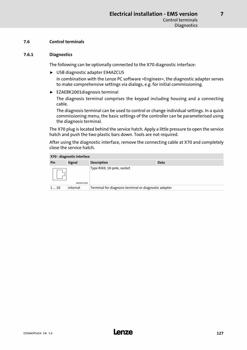
Electrical installation − EMS versionControl terminals
Diagnostics
7
� 127EDS84DPS424 EN 5.0
7.6 Control terminals
7.6.1 Diagnostics
The following can be optionally connected to the X70 diagnostic interface:
ƒ USB diagnostic adapter E94AZCUS
In combination with the Lenze PC software »Engineer«, the diagnostic adapter servesto make comprehensive settings via dialogs, e.g. for initial commissioning.
ƒ EZAEBK2001diagnosis terminal
The diagnosis terminal comprises the keypad including housing and a connectingcable.
The diagnosis terminal can be used to control or change individual settings. In a quickcommissioning menu, the basic settings of the controller can be parameterised usingthe diagnosis terminal.
The X70 plug is located behind the service hatch. Apply a little pressure to open the servicehatch and push the two plastic bars down. Tools are not required.
After using the diagnostic interface, remove the connecting cable at X70 and completelyclose the service hatch.
X70 − diagnostic interface
Pin Signal Description Data
Type RJ69, 10−pole, socket
8400HLC009
1 ... 10 internal Terminal for diagnosis terminal or diagnostic adapter
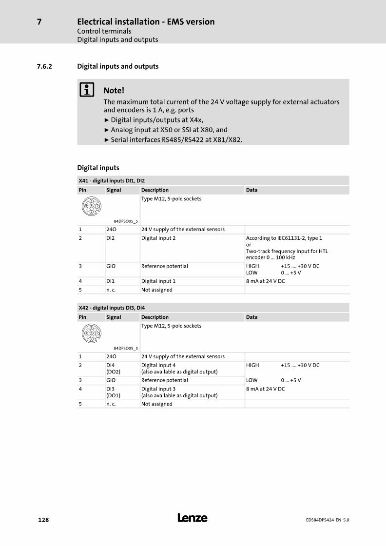
Electrical installation − EMS versionControl terminalsDigital inputs and outputs
7
� 128 EDS84DPS424 EN 5.0
7.6.2 Digital inputs and outputs
� Note!
The maximum total current of the 24 V voltage supply for external actuatorsand encoders is 1 A, e.g. ports
ƒ Digital inputs/outputs at X4x,
ƒ Analog input at X50 or SSI at X80, and
ƒ Serial interfaces RS485/RS422 at X81/X82.
Digital inputs
X41 − digital inputs DI1, DI2
Pin Signal Description Data
Type M12, 5−pole sockets
84DPSO05_5
1 24O 24 V supply of the external sensors
2 DI2 Digital input 2 According to IEC61131−2, type 1orTwo−track frequency input for HTLencoder 0 ... 100 kHz
3 GIO Reference potential HIGHLOW
+15 .... +30 V DC0 ... +5 V
4 DI1 Digital input 1 8 mA at 24 V DC
5 n. c. Not assigned
X42 − digital inputs DI3, DI4
Pin Signal Description Data
Type M12, 5−pole sockets
84DPSO05_5
1 24O 24 V supply of the external sensors
2 DI4(DO2)
Digital input 4(also available as digital output)
HIGH +15 .... +30 V DC
3 GIO Reference potential LOW 0 ... +5 V
4 DI3(DO1)
Digital input 3(also available as digital output)
8 mA at 24 V DC
5 n. c. Not assigned
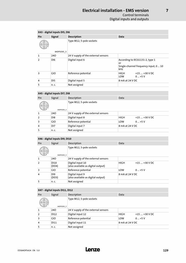
Electrical installation − EMS versionControl terminals
Digital inputs and outputs
7
� 129EDS84DPS424 EN 5.0
X43 − digital inputs DI5, DI6
Pin Signal Description Data
Type M12, 5−pole sockets
84DPSO05_5
1 24O 24 V supply of the external sensors
2 DI6 Digital input 6 According to IEC61131−2, type 1orSingle−channel frequency input, 0 ... 10kHz
3 GIO Reference potential HIGHLOW
+15 .... +30 V DC0 ... +5 V
4 DI5 Digital input 5 8 mA at 24 V DC
5 n. c. Not assigned
X45 − digital inputs DI7, DI8
Pin Signal Description Data
84DPSO05_5
Type M12, 5−pole sockets
1 24O 24 V supply of the external sensors
2 DI8 Digital input 8 HIGH +15 .... +30 V DC
3 GIO Reference potential LOW 0 ... +5 V
4 DI7 Digital input 7 8 mA at 24 V DC
5 n. c. Not assigned
X46 − digital inputs DI9, DI10
Pin Signal Description Data
84DPSO05_5
Type M12, 5−pole sockets
1 24O 24 V supply of the external sensors
2 DI10(DO4)
Digital input 10(also available as digital output)
HIGH +15 .... +30 V DC
3 GIO Reference potential LOW 0 ... +5 V
4 DI9(DO3)
Digital input 9(also available as digital output)
8 mA at 24 V DC
5 n. c. Not assigned
X47 − digital inputs DI11, DI12
Pin Signal Description Data
84DPSO05_5
Type M12, 5−pole sockets
1 24O 24 V supply of the external sensors
2 DI12 Digital input 12 HIGH +15 .... +30 V DC
3 GIO Reference potential LOW 0 ... +5 V
4 DI11 Digital input 11 8 mA at 24 V DC
5 n. c. Not assigned
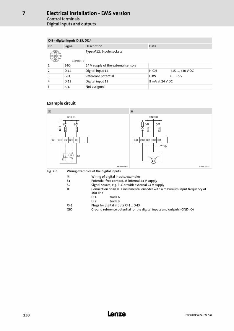
Electrical installation − EMS versionControl terminalsDigital inputs and outputs
7
� 130 EDS84DPS424 EN 5.0
X48 − digital inputs DI13, DI14
Pin Signal Description Data
84DPSO05_5
Type M12, 5−pole sockets
1 24O 24 V supply of the external sensors
2 DI14 Digital input 14 HIGH +15 .... +30 V DC
3 GIO Reference potential LOW 0 ... +5 V
4 DI13 Digital input 13 8 mA at 24 V DC
5 n. c. Not assigned
Example circuit
�
DI1
S1
X41
GND-IO
GIO24O
3.3
k
3.3
k
DI2
S2
=-
+
DI1X41
GND-IO
GIO24O
3.3
k
3.3
k
DI2
8400DIO045 8400DIO022
Fig. 7−5 Wiring examples of the digital inputs
� Wiring of digital inputs, examples:S1 Potential−free contact, at internal 24 V supplyS2 Signal source, e.g. PLC or with external 24 V supply Connection of an HTL incremental encoder with a maximum input frequency of
100 kHzDI1 track ADI2 track B
X41 Plugs for digital inputs X41 ... X43GIO Ground reference potential for the digital inputs and outputs (GND−IO)
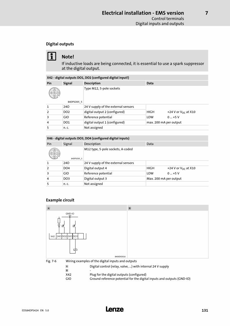
Electrical installation − EMS versionControl terminals
Digital inputs and outputs
7
� 131EDS84DPS424 EN 5.0
Digital outputs
� Note!
If inductive loads are being connected, it is essential to use a spark suppressorat the digital output.
X42 − digital outputs DO1, DO2 (configured digital input!)
Pin Signal Description Data
Type M12, 5−pole sockets
84DPSO05_5
1 24O 24 V supply of the external sensors
2 DO2 digital output 2 (configured) HIGH +24 V or VDC at X10
3 GIO Reference potential LOW 0 ... +5 V
4 DO1 digital output 1 (configured) max. 200 mA per output
5 n. c. Not assigned
X46 − digital outputs DO3, DO4 (configured digital inputs)
Pin Signal Description Data
84DPSO05_5
M12 type, 5−pole sockets, A−coded
1 24O 24 V supply of the external sensors
2 DO4 Digital output 4 HIGH +24 V or VDC at X10
3 GIO Reference potential LOW 0 ... +5 V
4 DO3 Digital output 3 Max. 200 mA per output
5 n. c. Not assigned
Example circuit
�
DO1X42
GND-IO
GIO24O DO2
8400DIO016
Fig. 7−6 Wiring examples of the digital inputs and outputs
� Digital control (relay, valve, ...) with internal 24 V supply −X42 Plug for the digital outputs (configured)GIO Ground reference potential for the digital inputs and outputs (GND−IO)
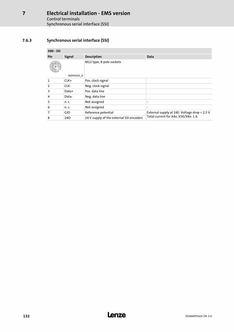
Electrical installation − EMS versionControl terminalsSynchronous serial interface (SSI)
7
� 132 EDS84DPS424 EN 5.0
7.6.3 Synchronous serial interface (SSI)
X80 − SSI
Pin Signal Description Data
M12 type, 8−pole sockets
84DPSO05_8
1 CLK+ Pos. clock signal
2 CLK− Neg. clock signal
3 Data+ Pos. data line
4 Data− Neg. data line
5 n. c. Not assigned −
6 n. c. Not assigned −
7 GIO Reference potential External supply at 24E: Voltage drop < 2.5 VTotal current for X4x, X50/X8x: 1 A8 24O 24 V supply of the external SSI encoders
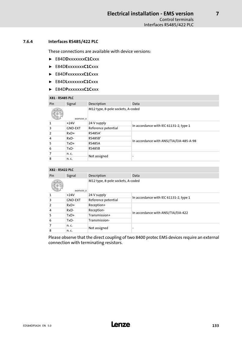
Electrical installation − EMS versionControl terminals
Interfaces RS485/422 PLC
7
� 133EDS84DPS424 EN 5.0
7.6.4 Interfaces RS485/422 PLC
These connections are available with device versions:
ƒ E84DDxxxxxxxC1Cxxx
ƒ E84DExxxxxxxC1Cxxx
ƒ E84DFxxxxxxxC1Cxxx
ƒ E84DLxxxxxxxC1Cxxx
ƒ E84DPxxxxxxxC1Cxxx
X81 − RS485 PLC
Pin Signal Description Data
84DPSO05_8
M12 type, 8−pole sockets, A−coded
1 +24V 24 V supplyIn accordance with IEC 61131−2, type 1
3 GND−EXT Reference potential
2 RxD+ RS485A’
In accordance with ANSI/TIA/EIA−485−A−984 RxD− RS485B’
5 TxD+ RS485A
6 TxD− RS485B
7 n. c.Not assigned −
8 n. c.
X82 − RS422 PLC
Pin Signal Description Data
84DPSO05_8
M12 type, 8−pole sockets, A−coded
1 +24V 24 V supplyIn accordance with IEC 61131−2, type 1
3 GND−EXT Reference potential
2 RxD+ Reception+
In accordance with ANSI/TIA/EIA−4224 RxD− Reception−
5 TxD+ Transmission+
6 TxD− Transmission−
7 n. c.Not assigned −
8 n. c.
Please observe that the direct coupling of two 8400 protec EMS devices require an externalconnection with terminating resistors.
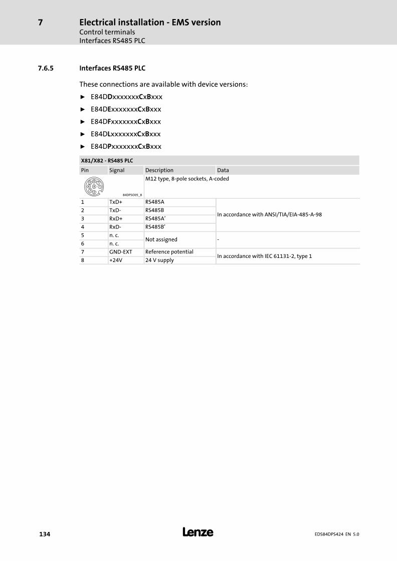
Electrical installation − EMS versionControl terminalsInterfaces RS485 PLC
7
� 134 EDS84DPS424 EN 5.0
7.6.5 Interfaces RS485 PLC
These connections are available with device versions:
ƒ E84DDxxxxxxxCxBxxx
ƒ E84DExxxxxxxCxBxxx
ƒ E84DFxxxxxxxCxBxxx
ƒ E84DLxxxxxxxCxBxxx
ƒ E84DPxxxxxxxCxBxxx
X81/X82 − RS485 PLC
Pin Signal Description Data
84DPSO05_8
M12 type, 8−pole sockets, A−coded
1 TxD+ RS485A
In accordance with ANSI/TIA/EIA−485−A−982 TxD− RS485B
3 RxD+ RS485A’
4 RxD− RS485B’
5 n. c.Not assigned −
6 n. c.
7 GND−EXT Reference potentialIn accordance with IEC 61131−2, type 1
8 +24V 24 V supply
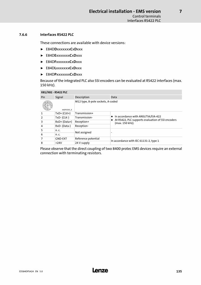
Electrical installation − EMS versionControl terminals
Interfaces RS422 PLC
7
� 135EDS84DPS424 EN 5.0
7.6.6 Interfaces RS422 PLC
These connections are available with device versions:
ƒ E84DDxxxxxxxCxDxxx
ƒ E84DExxxxxxxCxDxxx
ƒ E84DFxxxxxxxCxDxxx
ƒ E84DLxxxxxxxCxDxxx
ƒ E84DPxxxxxxxCxDxxx
Because of the integrated PLC also SSI encoders can be evaluated at RS422 interfaces (max.150 kHz).
X81/X82 − RS422 PLC
Pin Signal Description Data
84DPSO05_8
M12 type, 8−pole sockets, A−coded
1 TxD+ (CLK+) Transmission+� In accordance with ANSI/TIA/EIA−422� At RS422, PLC supports evaluation of SSI encoders
(max. 150 kHz).
2 TxD− (CLK−) Transmission−
3 RxD+ (Data+) Reception+
4 RxD− (Data−) Reception−
5 n. c.Not assigned −
6 n. c.
7 GND−EXT Reference potentialIn accordance with IEC 61131−2, type 1
8 +24V 24 V supply
Please observe that the direct coupling of two 8400 protec EMS devices require an externalconnection with terminating resistors.
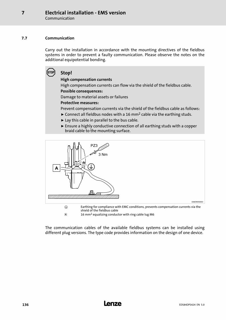
Electrical installation − EMS versionCommunication
7
� 136 EDS84DPS424 EN 5.0
7.7 Communication
Carry out the installation in accordance with the mounting directives of the fieldbussystems in order to prevent a faulty communication. Please observe the notes on theadditional equipotential bonding.
Stop!
High compensation currents
High compensation currents can flow via the shield of the fieldbus cable.
Possible consequences:
Damage to material assets or failures
Protective measures:
Prevent compensation currents via the shield of the fieldbus cable as follows:
ƒ Connect all fieldbus nodes with a 16 mm2 cable via the earthing studs.
ƒ Lay this cable in parallel to the bus cable.
ƒ Ensure a highly conductive connection of all earthing studs with a copperbraid cable to the mounting surface.
E84DWX0003
� Earthing for compliance with EMC conditions, prevents compensation currents via theshield of the fieldbus cable
� 16 mm2 equalizing conductor with ring cable lug M6
The communication cables of the available fieldbus systems can be installed usingdifferent plug versions. The type code provides information on the design of one device.
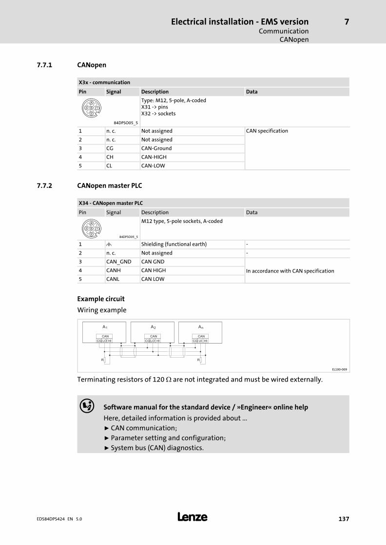
Electrical installation − EMS versionCommunication
CANopen
7
� 137EDS84DPS424 EN 5.0
7.7.1 CANopen
X3x − communication
Pin Signal Description Data
Type: M12, 5−pole, A−codedX31 −> pinsX32 −> sockets
84DPSO05_5
1 n. c. Not assigned CAN specification
2 n. c. Not assigned
3 CG CAN−Ground
4 CH CAN−HIGH
5 CL CAN−LOW
7.7.2 CANopen master PLC
X34 − CANopen master PLC
Pin Signal Description Data
84DPSO05_5
M12 type, 5−pole sockets, A−coded
1 � Shielding (functional earth) −
2 n. c. Not assigned −
3 CAN_GND CAN GND
In accordance with CAN specification4 CANH CAN HIGH
5 CANL CAN LOW
Example circuit
Wiring example
CG
CAN
LO HI CG
CAN
LO HI CG
CAN
LO HI
R R
AnA2A1
EL100−009
Terminating resistors of 120 � are not integrated and must be wired externally.
� Software manual for the standard device / »Engineer« online help
Here, detailed information is provided about ...
ƒ CAN communication;
ƒ Parameter setting and configuration;
ƒ System bus (CAN) diagnostics.
Commissioning8
� 138 EDS84DPS424 EN 5.0
8 Commissioning
� Note!ƒ Please observe the general safety instructions (� 13).
ƒ Please observe the notes regarding residual hazards (� 19).
� Danger!Uncontrolled motor movements may occur
Under certain conditions, the motor may rotate after mains connection.
Possible consequences:
ƒ Near the machine or plant, situations may arise that are hazardous topersons.
ƒ The machine or plant may be damaged by an unexpected start.
Protective measures:
ƒ Commissioning with external 24 V supply and without mains voltage
ƒ Remove motor connector X21. An active motor temperature monitoringprevents a motor voltage from being output. If the monitoring isdeactivated, a voltage may be applied at the plug.
ƒ Ensure that no setpoint is applied.
CommissioningBefore switching on
8
� 139EDS84DPS424 EN 5.0
8.1 Before switching on
� Note!Please observe during transport, storage and operation:
ƒ Cover unused connectors for control connections and interfaces with theplastic covers provided to preserve the certified safety technology features.
Check that all connectors are properly locked in order to ensure trouble−free operation.
� Note!ƒ Comply with the respective switch−on sequence.
ƒ In case of trouble during commissioning, the following supports you:– The "Diagnostics" chapter– The online help in the »Engineer«– The software manual of the prevailing device version
In order to avoid injury to persons or damage to material assets, check ...
... before switching on the mains voltage:
ƒ Check the wiring for completeness, short−circuit and earth fault
ƒ The "emergency switching off" function of the entire plant
ƒ The motor circuit configuration (star/delta) must be adapted to the output voltageof the controller
ƒ The in−phase connection of the motor
ƒ The direction of rotation of the incremental encoder (if available)
...the setting of the most important drive parameters before controller enable to ensurethe following:
ƒ The V/f rated frequency is adapted to the motor circuit configuration!
ƒ The drive parameters relevant for your application are set correctly!
ƒ The configuration of the analog and digital inputs and outputs are adapted to thewiring!
� Tip!Use the L−force "Engineer" to carry out extensive parameter setting andconfiguration. The L−force keypad can be used for quick commissioning andchecking individual parameters. If you want to use the L−force "Engineer", theonline help and the software documentation for the controller assist you.
CommissioningPreparing the commissioning procedure
8
� 140 EDS84DPS424 EN 5.0
8.2 Preparing the commissioning procedure
You need the following for commissioning:
ƒ Computer with a Windows® operating system (XP, 7 or 2000)
ƒ Lenze »Engineer« PC software
ƒ Connection to the controller via an interface, e.g.
– diagnostic interface X70 with diagnostic USB adapter
– Fieldbus
ƒ Software manual for the technology application used
ƒ Hardware manual (GHB)
ƒ Manual for the drive−based safety
ƒ Communication manual for the network of the automation platform
ƒ 24 V voltage supply for the control electronics of the controller
– by switching on the mains voltage
– alternatively by a 24−V buffer voltage
Follow the instructions of the software and/or read the documentation.
Selection of the appropriate commissioning tool
There are two ways to commission the 8400 frequency inverter:
ƒ Commissioning using the keypad (or diagnosis terminal)
– For simple drive tasks such as quick commissioning of the ’Speed closed−loopcontrol’ standard application
ƒ Commissioning using the »Engineer«
– For rather demanding drive tasks such as ’Table positioning’ of the HighLineversion
– Supported by online help and accompanying software documentation (softwaremanual)
� Note!
The following can be used at the diagnostic interface X70:
ƒ Diagnosis terminal X401 (EZAEBK2003)– The described settings with the keypad X401 can also be carried out with
the diagnosis terminal X401.
ƒ USB diagnostic adapter (E94AZCUS)
CommissioningPreparing the commissioning procedure
8
� 141EDS84DPS424 EN 5.0
Notes on commissioning in the case of an external 24 V supply
The following sequence must be observed when commissioning devices with an external24 V supply:
ƒ Switch−on
– Connection of the external 24 V supplyThe control electronics and fieldbus communication are started and the displayshows the "LU" message (undervoltage in the DC bus)
– Connection of the 400 V mains voltageThe message in the display goes off / changes over to .
ƒ Switch−off
– Switch−off of the 400 V mains voltage
– Switch−off of the 24 V supply
� Note!
The functions of the control electronics become inactive when the 24 V supplyis switched off. The switch function of Ethernet−based fieldbuses is alsoinactive.
Switching the 24 V supply when the mains voltage is applied may lead to anerror status in higher−level controls.
Notes for the commissioning of EMS versions
For EMS version devices, in addition the following has to be observed:
ƒ Devices with a rocker switch control element
– To enable the controller, the rocker switch has to be operated.
– Operating the rocker switch again inhibits the controller.
ƒ Device without a rocker switch control element
The controller has to be enabled using the available communication options.
CommissioningPreparing the commissioning procedure
8
� 142 EDS84DPS424 EN 5.0
Notes for motor operation
Danger!
ƒ For thermal reasons, continuous operation of self−ventilated motors at lowfield frequency and rated motor current is not permissible. If required,activate a motor temperature monitoring with C00585– motor temperature monitoring with I2xt (see software manual)– motor temperature monitoring with motor PTC (see software manual).
ƒ Select 87−Hz operation under code C00015 if an asynchronous motor indelta connection (nameplate data: 400 V�/230 V�) is to be operated on afrequency inverter for a supply voltage of 400 V.
� Tip!
In the Lenze setting, the "linear V/f characteristic" operating mode is set asmotor control. The parameter settings are preset so that if the frequencyinverter and the 50 Hz asynchronous machine match in terms of power, thecontroller is ready for operation without any further need for parameterisationand the motor operates satisfactorily.
Recommendations for the following application cases
ƒ If the frequency inverter and the motor differ strongly in terms ofpower
– Set code C00022 (Imax limit in motor mode) to 2.0 IN(motor).
ƒ If a high starting torque is required
– When the motor is idling, set the code C00016 (Vmin boost) so that arated motor current flows with a field frequency f = 3 Hz (C00058).
ƒ For noise reduction
– Set code C00018 to the value "3" (switching frequency16 kHzsin var).
ƒ If a high torque without feedback is to be available at low speeds, werecommend the "vector control" mode.
CommissioningQuick commissioning
8
� 143EDS84DPS424 EN 5.0
8.3 Quick commissioning
Target
For test and demonstration purposes, the load−free motor shall be rotated in best timewith an amount of wiring as little as possible and few settings.
Keypad or setpoint potentiometer
For this simple application, you can choose between two drive control options:
ƒ Keypad control (� 144), i.e. the X400 keypad is used as setpoint source
ƒ Terminal control (� 146), i.e. a setpoint potentiometer connected to the controllerterminals is used as setpoint source
Diagnostics
In addition to the keypad, also use the LEDs on the front of the controller for drivediagnostics:
ƒ Two LEDs indicate the device status (DRIVE READY and DRIVE ERROR)
ƒ Two LEDs indicate the bus status (CAN−RUN and CAN−ERROR)
The LEDs for the bus status are less important during quick commissioning.
� Tip!
The handling of the keypad X401 or the diagnosis terminal X401 is describedin the operating instructions. The instructions are supplied with the keypadand are also included in electronic form on the product CD "L−force InverterDrives 8400".
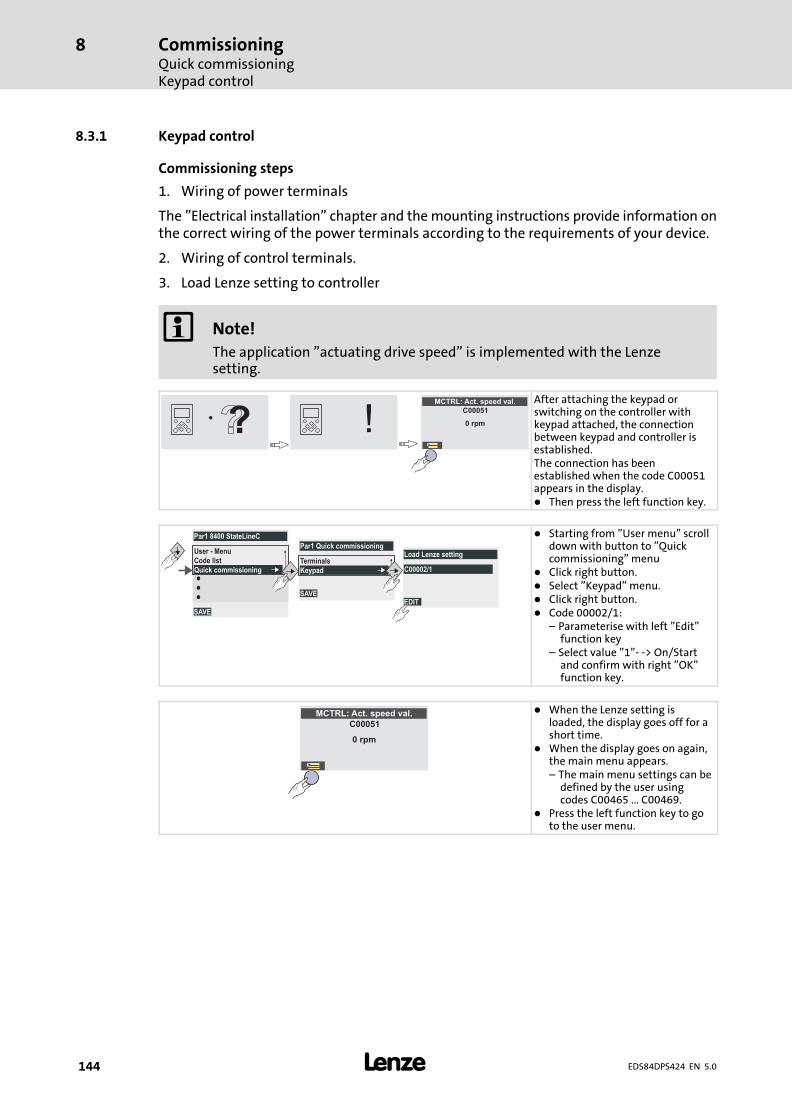
CommissioningQuick commissioningKeypad control
8
� 144 EDS84DPS424 EN 5.0
8.3.1 Keypad control
Commissioning steps
1. Wiring of power terminals
The "Electrical installation" chapter and the mounting instructions provide information onthe correct wiring of the power terminals according to the requirements of your device.
2. Wiring of control terminals.
3. Load Lenze setting to controller
� Note!
The application "actuating drive speed" is implemented with the Lenzesetting.
MCTRL: Act. speed val.
C00051
0 rpm
After attaching the keypad orswitching on the controller withkeypad attached, the connectionbetween keypad and controller isestablished.The connection has beenestablished when the code C00051appears in the display.� Then press the left function key.
SAVE
Par1 8400 StateLineC
User - Menu
Code list
Quick commissioning
SAVE
Par1 Quick commissioning
Terminals
Keypad
EDIT
Load Lenze setting
C00002/1
� Starting from "User menu" scrolldown with button to "Quickcommissioning" menu
� Click right button.� Select "Keypad" menu.� Click right button.� Code 00002/1:
– Parameterise with left "Edit"function key
– Select value "1"− −> On/Startand confirm with right "OK"function key.
MCTRL: Act. speed val.
C00051
0 rpm
� When the Lenze setting isloaded, the display goes off for ashort time.
� When the display goes on again,the main menu appears.– The main menu settings can be
defined by the user usingcodes C00465 ... C00469.
� Press the left function key to goto the user menu.
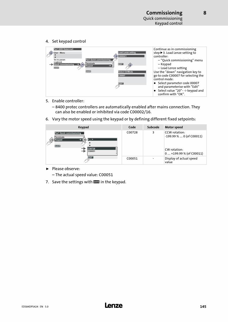
CommissioningQuick commissioning
Keypad control
8
� 145EDS84DPS424 EN 5.0
4. Set keypad control
EDIT
Select CtrlMode
C00007
Quick commissioning
SAVE
Par1 Quick commissioning
Terminals
KeypadSAVE
Par1 8400 StateLineC
User - Menu
Logbook
Go to param
Quick commissioning EDIT
Load Lenze setting
C00002/1
Continue as in commissioningstep !3. Load Lenze setting tocontroller:
– "Quick commissioning" menu– Keypad– Load Lenze setting
Use the "down" navigation key togo to code C00007 for selecting thecontrol mode:� Select parameter code 00007
and parameterise with "Edit"� Select value "20"− −> keypad and
confirm with "OK".
5. Enable controller:
– 8400 protec controllers are automatically enabled after mains connection. Theycan also be enabled or inhibited via code C00002/16.
6. Vary the motor speed using the keypad or by defining different fixed setpoints:
Keypad Code Subcode Motor speed
EDIT
< ... >
C00728
C00051
SAVE
Par1 Quick commissioning
Terminals
Keypad
C00728 3 CCW rotation:−199.99 % .... 0 (of C00011)
CW rotation:0 .... +199.99 % (of C00011)
C00051 − Display of actual speedvalue
ƒ Please observe:
– The actual speed value: C00051
7. Save the settings with " in the keypad.
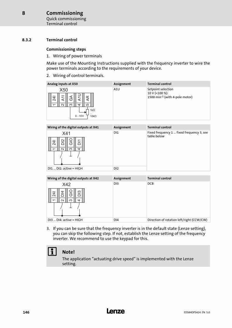
CommissioningQuick commissioningTerminal control
8
� 146 EDS84DPS424 EN 5.0
8.3.2 Terminal control
Commissioning steps
1. Wiring of power terminals
Make use of the Mounting Instructions supplied with the frequency inverter to wire thepower terminals according to the requirements of your device.
2. Wiring of control terminals.
Analog inputs at X50 Assignment Terminal control
X50
24I
A1
I
GA
A1
U
AR
1 2 3 4 5
0...10V
1k...10k
Ω
Ω
A1U Setpoint selection10 V (=100 %):1500 min−1 (with 4−pole motor)
Wiring of the digital outputs at X41 Assignment Terminal control
X41
24I
DI2
GIO
DI1
1 2 3 4
DI1 Fixed frequency 1 ... fixed frequency 3, seetable below
DI1 ... DI2: active = HIGH DI2
Wiring of the digital outputs at X42 Assignment Terminal control
X42
24I
GIO
DI3
1 2 3 4
DI4
DI3 DCB
DI3 ... DI4: active = HIGH DI4 Direction of rotation left/right (CCW/CW)
3. If you can be sure that the frequency inverter is in the default state (Lenze setting),you can skip the following step. If not, establish the Lenze setting of the frequencyinverter. We recommend to use the keypad for this.
� Note!
The application "actuating drive speed" is implemented with the Lenzesetting.
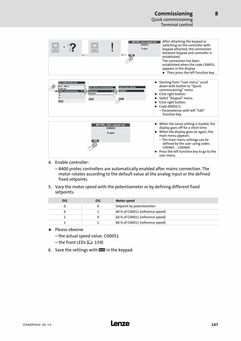
CommissioningQuick commissioning
Terminal control
8
� 147EDS84DPS424 EN 5.0
MCTRL: Act. speed val.
C00051
0 rpm
After attaching the keypad orswitching on the controller withkeypad attached, the connectionbetween keypad and controller isestablished.The connection has beenestablished when the code C00051appears in the display.� Then press the left function key.
SAVE
Par1 8400 StateLineC
User - Menu
Code list
Quick commissioning
SAVE
Par1 Quick commissioning
Terminals
Keypad
EDIT
Load Lenze setting
C00002/1
� Starting from "User menu" scrolldown with button to "Quickcommissioning" menu
� Click right button.� Select "Keypad" menu.� Click right button.� Code 00002/1:
– Parameterise with left "Edit"function key
MCTRL: Act. speed val.
C00051
0 rpm
� When the Lenze setting is loaded, thedisplay goes off for a short time.
� When the display goes on again, themain menu appears.– The main menu settings can be
defined by the user using codesC00465 ... C00469.
� Press the left function key to go to theuser menu.
4. Enable controller:
– 8400 protec controllers are automatically enabled after mains connection. Themotor rotates according to the default value at the analog input or the definedfixed setpoints.
5. Vary the motor speed with the potentiometer or by defining different fixedsetpoints:
DI2 DI1 Motor speed
0 0 Setpoint by potentiometer
0 1 40 % of C00011 (reference speed)
1 0 60 % of C00011 (reference speed)
1 1 80 % of C00011 (reference speed)
ƒ Please observe
– the actual speed value: C00051
– the front LEDs (� 159)
6. Save the settings with " in the keypad.
Braking operationBraking operation without additional measures
9
� 148 EDS84DPS424 EN 5.0
9 Braking operation
When electric motors are braked, the kinetic energy of the drive train is fed back to the DCbus in generator mode. This energy results in an increased DC−bus voltage. Variousstrategies are available to avoid an overvoltage in the DC bus:
ƒ Braking operation without additional measures
This includes functions integrated in the controller which do not require external brakeresistors and can be parameterised using the »Engineer«:
– DC injection brake DCB
– Stopping of the ramp function generator
– "Inverter motor brake" function (from software version 01.01)
The braking operation without external brake resistor is suitable for simpleapplications which do not require strict compliance with the deceleration ramp. Hence,this is a cost−saving procedure since a brake resistor is not required. A combination ofall above−mentioned braking procedures is also possible, e.g. to perform emergencybraking in the event of a brake resistor failure.
ƒ Braking operation with external brake resistor
ƒ Braking operation with spring−applied brake
Stop!
ƒ The two braking procedures "Stopping of the ramp function generator" and"Inverter motor brake" are only active in speed−controlled applications if theposition controller does not interfere!
ƒ Do not additionally adapt the motor load (I2xt) if the inverter motor brake isused!In this case, the motor may thermally overload or the motor overloadmonitoring (I2xt) may be working incorrectly!
9.1 Braking operation without additional measures
DC injection brake DCB
To decelerate small masses, the "DC injection brake DCB" function can be parameterised.DC−injection braking enables a quick deceleration of the drive to standstill without theneed for an external brake resistor.
ƒ Code C00036 can be used to select the braking current.
ƒ The maximum braking torque to be realised by the DC braking current amounts toapprox. 20 ... 30 % of the rated motor torque. It is lower compared to braking actionin generator mode with external brake resistor.
ƒ Automatic DC−injection braking (Auto−DCB) improves the starting performance ofthe motor when the operation mode without speed feedback is used.
Further information on the relevant parameters can be obtained from the softwaremanual.
Braking operationBraking operation without additional measures
9
� 149EDS84DPS424 EN 5.0
Stopping of the ramp function generator
The "Stopping of the ramp function generator" response is set in C00175. If the brakechopper threshold in the DC−bus connection which results from C00173 and C00174 isexceeded, the ramp function generator is stopped.
This function is suitable for braking operations with reduced dynamics and torqueoscillations.
Inverter motor brake
During this alternative braking procedure which can be selected in C00175, the energyconversion of the regenerative energy of the motor is achieved by dynamicacceleration/deceleration while the ramp function generator is ramped down.
The ramp function generator is stopped during acceleration. Using a hysteresis controller,the speed set in C00987 is added to the speed setpoint. The sign of the current actual speedis considered in the process. The ramp function generator is also stopped if an overvoltageoccurs.
If the DC−bus voltage falls below a defined DC−bus voltage potential of the hysteresiscontroller, the connected additive speed is removed and the ramp function generator isenabled again.
The energy which results from the alternating acceleration and braking procedure due tothis switching operation is converted into heat in the motor.
In general, the following applies to the "Inverter motor brake" function:
ƒ The regenerative energy converted in the motor can be increased and the brakingprocedure can be accelerated if the additive speed setpoint is decelerated and thecorresponding filter time constant is reduced.
ƒ There may be procedure−related torque oscillations. Mechanical vibrations can bereduced by reducing the additive speed setpoint (C00987) or by increasing the filtertime constant.
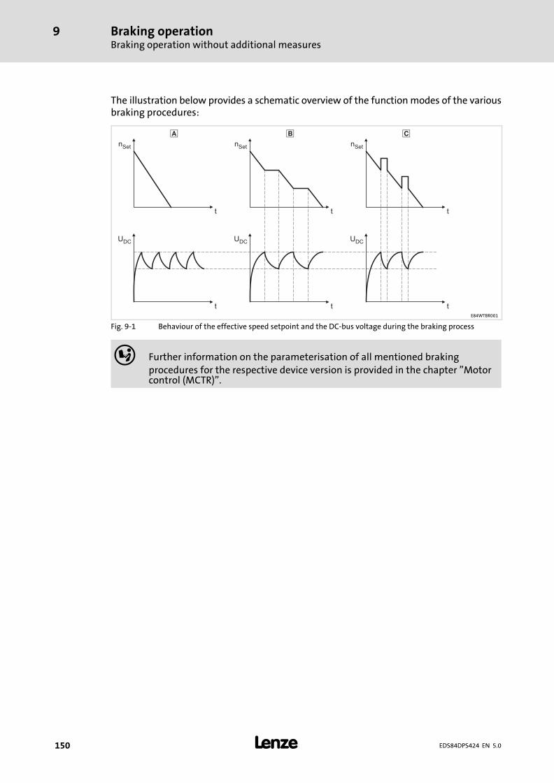
Braking operationBraking operation without additional measures
9
� 150 EDS84DPS424 EN 5.0
The illustration below provides a schematic overview of the function modes of the variousbraking procedures:
nSet
t
nSet
t
� �n
Set
t
�
t tt
UDC
UDC
UDC
E84WTBR001
Fig. 9−1 Behaviour of the effective speed setpoint and the DC−bus voltage during the braking process
� Further information on the parameterisation of all mentioned brakingprocedures for the respective device version is provided in the chapter "Motorcontrol (MCTR)".
Braking operationBraking operation with external brake resistor
9
� 151EDS84DPS424 EN 5.0
9.2 Braking operation with external brake resistor
To decelerate greater moments of inertia or with a longer operation in generator mode anexternal brake resistor is required. It converts braking energy into heat.
The brake resistor is connected if the DC−bus voltage exceeds the switching threshold. Thisprevents the controller from setting pulse inhibit through the "Overvoltage" fault and thedrive from coasting. The external brake resistor serves to control the braking process at anytime.
The brake chopper integrated in the controller connects the external brake resistor.
ƒ Adapt the switching threshold to the mains voltage (C00173/C00714, see softwaremanual).
The rated data for the brake chopper are provided in the chapters 4.2.2 and 4.2.3.
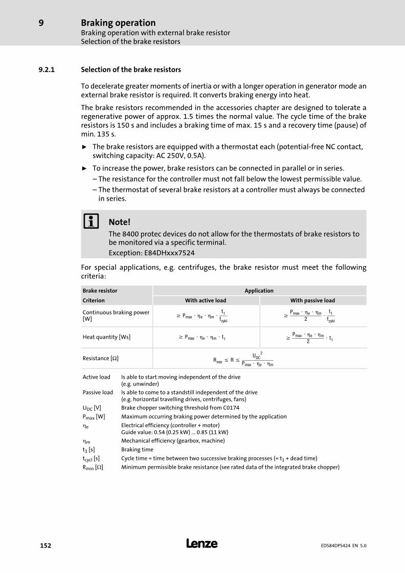
Braking operationBraking operation with external brake resistorSelection of the brake resistors
9
� 152 EDS84DPS424 EN 5.0
9.2.1 Selection of the brake resistors
To decelerate greater moments of inertia or with a longer operation in generator mode anexternal brake resistor is required. It converts braking energy into heat.
The brake resistors recommended in the accessories chapter are designed to tolerate aregenerative power of approx. 1.5 times the normal value. The cycle time of the brakeresistors is 150 s and includes a braking time of max. 15 s and a recovery time (pause) ofmin. 135 s.
ƒ The brake resistors are equipped with a thermostat each (potential−free NC contact,switching capacity: AC 250V, 0.5A).
ƒ To increase the power, brake resistors can be connected in parallel or in series.
– The resistance for the controller must not fall below the lowest permissible value.
– The thermostat of several brake resistors at a controller must always be connectedin series.
� Note!
The 8400 protec devices do not allow for the thermostats of brake resistors tobe monitored via a specific terminal.
Exception: E84DHxxx7524
For special applications, e.g. centrifuges, the brake resistor must meet the followingcriteria:
Brake resistor Application
Criterion With active load With passive load
Continuous braking power[W]
� Pmax � �e � �m �t1tzykl
�Pmax � �e � �m
2�
t1tzykl
Heat quantity [Ws] � Pmax � �e � �m � t1 �Pmax � �e � �m
2� t1
Resistance [Ω] Rmin � R �UDC
2
Pmax � �e � �m
Active load Is able to start moving independent of the drive(e.g. unwinder)
Passive load Is able to come to a standstill independent of the drive(e.g. horizontal travelling drives, centrifuges, fans)
UDC [V] Brake chopper switching threshold from C0174
Pmax [W] Maximum occurring braking power determined by the application
e Electrical efficiency (controller + motor)Guide value: 0.54 (0.25 kW) ... 0.85 (11 kW)
m Mechanical efficiency (gearbox, machine)
t1 [s] Braking time
tcycl [s] Cycle time = time between two successive braking processes (= t1 + dead time)
Rmin [�] Minimum permissible brake resistance (see rated data of the integrated brake chopper)
Braking operationBraking operation with external brake resistor
Wiring of brake resistor
9
� 153EDS84DPS424 EN 5.0
9.2.2 Wiring of brake resistor
Danger!
Hazardous electrical voltage
During operation of the standard device and up to 3 minutes after power−offhazardous electrical voltages may occur at the terminals of the brake resistor.
Possible consequences:
ƒ Death or severe injuries when touching the terminals.
Protective measures:
ƒ Disconnect the standard device from the mains before working on the brakeresistor.
ƒ Check all power terminals for isolation from supply.
ƒ Select the mounting location so that the operating conditions mentioned inthe mounting instructions for the brake resistor are permanentlyguaranteed.
� Danger!
Hot surface
The brake resistor may get very hot. (For temperatures see the mountinginstructions for the brake resistor.)
Possible consequences:
ƒ Severe burns when touching the brake resistor.
ƒ Fire or smouldering fire if flammable material is placed near the brakeresistor or may get to it.
Protective measures:
ƒ Before working on the brake resistor, check its surface temperature.
ƒ Select the mounting location so that the operating conditions mentioned inthe mounting instructions for the brake resistor are permanentlyguaranteed.
ƒ Protect the mounting location through fire prevention.
Protect the brake resistor and controller against destruction caused by overload:
ƒ Establish an external safety shutdown using the thermostat of the brake resistor todisconnect the controller from the mains.
ƒ Exception for devices with special connection for the thermostat of the brakeresistor: Use the device−internal safety shutdown.
Connecting cable version
ƒ up to 0.5 m: twisted and unshielded
ƒ from 0.5 to 5 m: shielded
– Use shielded cables to meet the EMC requirements.
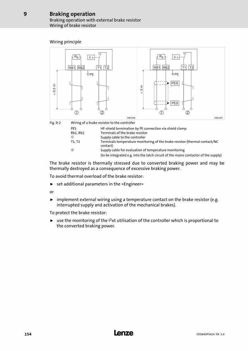
Braking operationBraking operation with external brake resistorWiring of brake resistor
9
� 154 EDS84DPS424 EN 5.0
Wiring principle
�
RB
RB1 RB2
<0.
5m
PE
T1 T2
�
RB
RB1 RB2
<5
m
PE
PES
PES
T1 T2
� �ERBG008 ERBG007
Fig. 9−2 Wiring of a brake resistor to the controller
PES HF−shield termination by PE connection via shield clampRb1, Rb2 Terminals of the brake resistor� Supply cable to the controllerT1, T2 Terminals temperature monitoring of the brake resistor (thermal contact/NC
contact)� Supply cable for evaluation of temperature monitoring
(to be integrated e.g. into the latch circuit of the mains contactor of the supply)
The brake resistor is thermally stressed due to converted braking power and may bethermally destroyed as a consequence of excessive braking power.
To avoid thermal overload of the brake resistor:
ƒ set additional parameters in the »Engineer«
or
ƒ implement external wiring using a temperature contact on the brake resistor (e.g.interrupted supply and activation of the mechanical brakes).
To protect the brake resistor:
ƒ use the monitoring of the I2xt utilisation of the controller which is proportional tothe converted braking power.
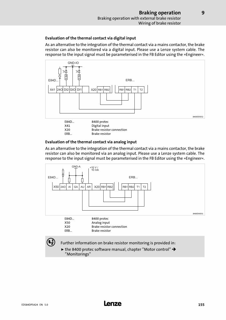
Braking operationBraking operation with external brake resistor
Wiring of brake resistor
9
� 155EDS84DPS424 EN 5.0
Evaluation of the thermal contact via digital input
As an alternative to the integration of the thermal contact via a mains contactor, the brakeresistor can also be monitored via a digital input. Please use a Lenze system cable. Theresponse to the input signal must be parameterised in the FB Editor using the »Engineer«.
DI1X41
GND-IO
GIO24O
3.3
k
3.3
k
DI2 RB2 RB2RB1 RB1 T1 T2
ERB...
X20
E84D...
8400DDI032
E84D... 8400 protecX41 Digital inputX20 Brake resistor connectionERB... Brake resistor
Evaluation of the thermal contact via analog input
As an alternative to the integration of the thermal contact via a mains contactor, the brakeresistor can also be monitored via an analog input. Please use a Lenze system cable. Theresponse to the input signal must be parameterised in the FB Editor using the »Engineer«.
GND-A
X50 24O
E84D...
GA RB2 RB2AI RB1 RB1AU T1AR T2
+10 V /10 mA
ERB...
X20
8400DAI031
E84D... 8400 protecX50 Analog inputX20 Brake resistor connectionERB... Brake resistor
� Further information on brake resistor monitoring is provided in:
ƒ the 8400 protec software manual, chapter "Motor control" �"Monitorings"
Braking operationOperation with spring−applied brakeIntroduction
9
� 156 EDS84DPS424 EN 5.0
9.3 Operation with spring−applied brake
9.3.1 Introduction
Stop!
The integrated brake control includes an electronic switch which can control amotor holding brake.
Only motor holding brakes which comply with the permissible data mentionedin the Technical Data may be connected to the integrated brake control. (Ifnecessary, the holding brake must be controlled without a brake control via adigital output and a coupling relay.)
If the permissible values mentioned in the Technical Data are not observed:
ƒ the brake control may be destroyed.
ƒ a safe operation of the motor holding brake is not ensured.
Lenze three−phase AC motors and G−motion geared motors can be equipped withspring−applied brakes (motor holding brakes). 8400 protec controllers have an integratedmotor brake control.
Braking operationOperation with spring−applied brake
Introduction
9
� 157EDS84DPS424 EN 5.0
Switching the brake
Switching of the brake can be controlled:
ƒ Fast switch design
An external motor brake control module is required for the switching operations andthe DC supply of the spring−applied brake. The suitable motor brake control modulemust be selected according to the rated data of the spring−applied brake.
The fast switch option also offers the possibility of a quick switch−off. Here, a relaycontact is controlled in the supply circuit of the coil via the controller.
Wiring: See motor connection for type Modular
ƒ "Integrated brake rectifier" version
The voltage required for controlling the motor brake is generated in the controller,dependent on the mains voltage value. The following motor brakes can be connected:
– to the 400−V mains: Coil voltage 180 V DC, max. 50 W
– to the 500−V mains: Coil voltage 225 V DC, max. 50 W
The rated coil voltage is neither increased nor reduced.
Wiring: See motor connection for type Q8/0
ƒ "24 V DC" version
The voltage required for controlling the motor brake is supplied to the controller by anexternal voltage source. The following motor brakes can be connected:
– Coil voltage 24 V DC
Wiring: See motor connection for type Q8/0
ƒ Cold brake design
The voltage required for controlling the motor brake is generated in the controllerproportionally to the mains voltage value. The following motor brakes can beconnected:
– to the 400 V mains: coil voltage 180 V DC
– to the 500 V mains: coil voltage 225 V DC
To ensure a safe release of the brake, 130 % of the rated coil voltage is connected to thecoil for 0.3 s. Then, this voltage is reduced to 65 % of the rated coil voltage.
Wiring: See motor connection for type Q8/0
Optionally, the switching of the brake can be controlled in addition:
ƒ Via an external control contact (e.g. PLC)
ƒ Via a brake switch which is connected to one of the digital outputs of the controller.The digital output must be parameterised accordingly.
The software manual provides further information on the parameterisation andintegrated brake management.
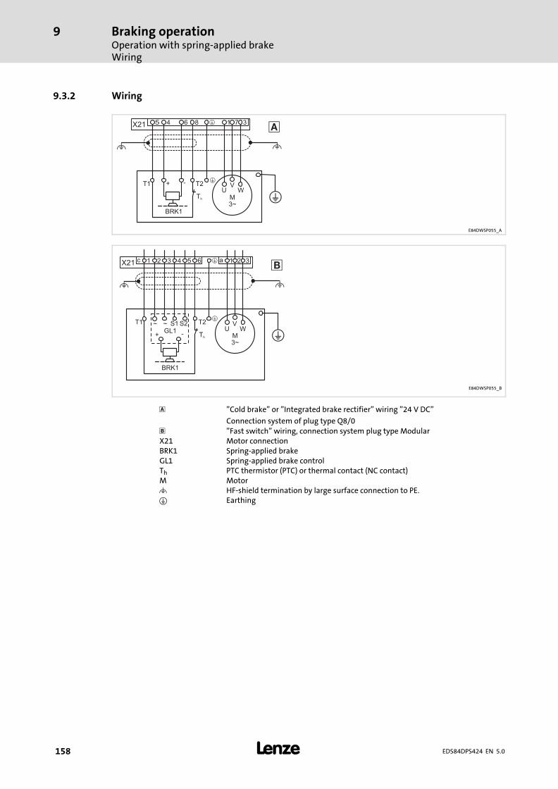
Braking operationOperation with spring−applied brakeWiring
9
� 158 EDS84DPS424 EN 5.0
9.3.2 Wiring
5 84 6 1 7 3X21 �
M3~
UV
W
�
�BRK1
T1 T2
Th
+ -
�
E84DWSP055_A
64 1 2 3X21 �c 1 2 3 a5
M3~
UV
W
�
�T1 T2
Th
BRK1
+ -
~ ~ S1 S2GL1
�
E84DWSP055_B
� "Cold brake" or "Integrated brake rectifier" wiring "24 V DC"
Connection system of plug type Q8/0 "Fast switch" wiring, connection system plug type ModularX21 Motor connectionBRK1 Spring−applied brakeGL1 Spring−applied brake controlTh PTC thermistor (PTC) or thermal contact (NC contact)M Motor� HF−shield termination by large surface connection to PE.� Earthing
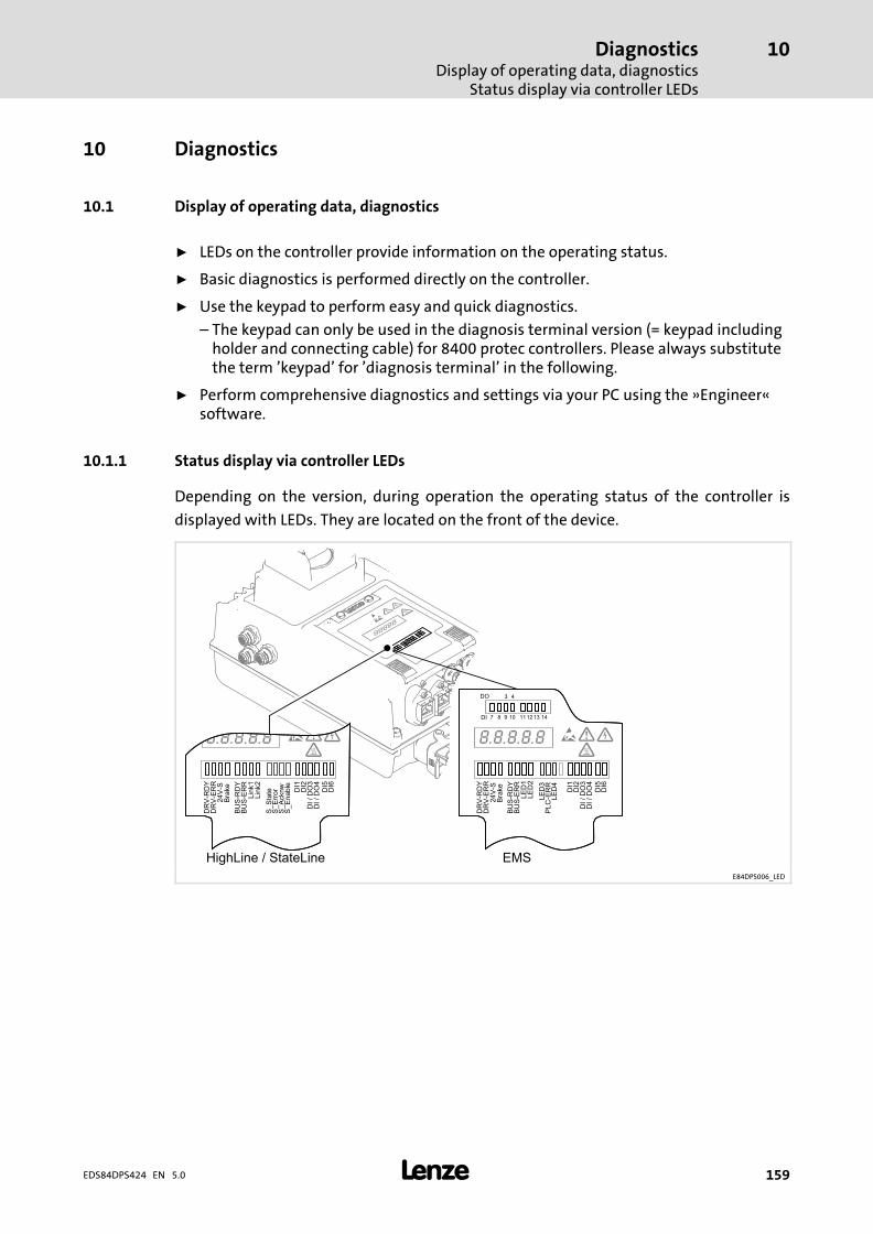
DiagnosticsDisplay of operating data, diagnostics
Status display via controller LEDs
10
� 159EDS84DPS424 EN 5.0
10 Diagnostics
10.1 Display of operating data, diagnostics
ƒ LEDs on the controller provide information on the operating status.
ƒ Basic diagnostics is performed directly on the controller.
ƒ Use the keypad to perform easy and quick diagnostics.
– The keypad can only be used in the diagnosis terminal version (= keypad includingholder and connecting cable) for 8400 protec controllers. Please always substitutethe term ’keypad’ for ’diagnosis terminal’ in the following.
ƒ Perform comprehensive diagnostics and settings via your PC using the »Engineer«software.
10.1.1 Status display via controller LEDs
Depending on the version, during operation the operating status of the controller is
displayed with LEDs. They are located on the front of the device.
E84DPS006_LED
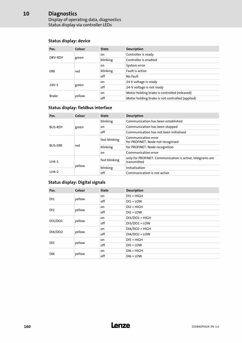
DiagnosticsDisplay of operating data, diagnosticsStatus display via controller LEDs
10
� 160 EDS84DPS424 EN 5.0
Status display: device
Pos. Colour State Description
DRV−RDY greenon Controller is ready
blinking Controller is enabled
ERR red
on System error
blinking Fault is active
off No fault
24V−S greenon 24 V voltage is ready
off 24−V voltage is not ready
Brake yellowon Motor holding brake is controlled (released)
off Motor holding brake is not controlled (applied)
Status display: fieldbus interface
Pos. Colour State Description
BUS−RDY green
blinking Communication has been established
on Communication has been stopped
off Communication has not been initialised
BUS−ERR red
fast blinkingCommunication errorfor PROFINET: Node not recognised
blinking for PROFINET: Node recognition
on Communication error
Link−1yellow
fast blinkingonly for PROFINET: Communication is active, telegrams aretransmitted
blinking InitialisationLink−2 off Communication is not active
Status display: Digital signals
Pos. Colour State Description
DI1 yellowon DI1 = HIGH
off DI1 = LOW
DI2 yellowon DI2 = HIGH
off DI2 = LOW
DI3/DO1 yellowon DI3/DO1 = HIGH
off DI3/DO1 = LOW
DI4/DO2 yellowon DI4/DO2 = HIGH
off DI4/DO2 = LOW
DI5 yellowon DI5 = HIGH
off DI5 = LOW
DI6 yellowon DI6 = HIGH
off DI6 = LOW
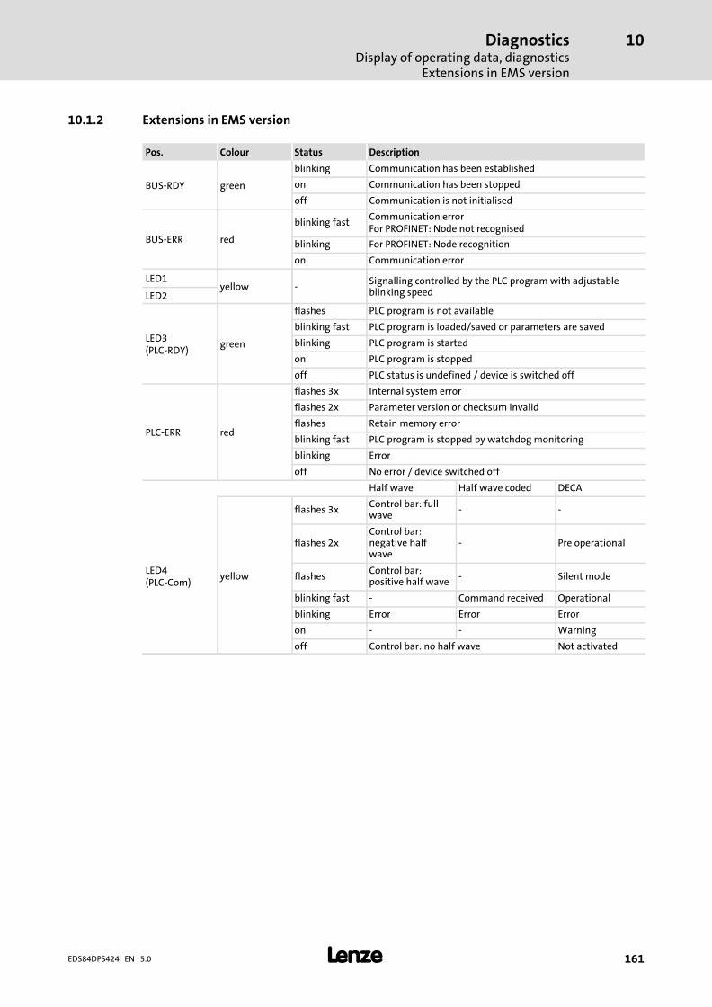
DiagnosticsDisplay of operating data, diagnostics
Extensions in EMS version
10
� 161EDS84DPS424 EN 5.0
10.1.2 Extensions in EMS version
Pos. Colour Status Description
BUS−RDY green
blinking Communication has been established
on Communication has been stopped
off Communication is not initialised
BUS−ERR red
blinking fastCommunication errorFor PROFINET: Node not recognised
blinking For PROFINET: Node recognition
on Communication error
LED1yellow −
Signalling controlled by the PLC program with adjustableblinking speedLED2
LED3(PLC−RDY)
green
flashes PLC program is not available
blinking fast PLC program is loaded/saved or parameters are saved
blinking PLC program is started
on PLC program is stopped
off PLC status is undefined / device is switched off
PLC−ERR red
flashes 3x Internal system error
flashes 2x Parameter version or checksum invalid
flashes Retain memory error
blinking fast PLC program is stopped by watchdog monitoring
blinking Error
off No error / device switched off
Half wave Half wave coded DECA
LED4(PLC−Com)
yellow
flashes 3xControl bar: fullwave
− −
flashes 2xControl bar:negative halfwave
− Pre operational
flashesControl bar:positive half wave
− Silent mode
blinking fast − Command received Operational
blinking Error Error Error
on − − Warning
off Control bar: no half wave Not activated
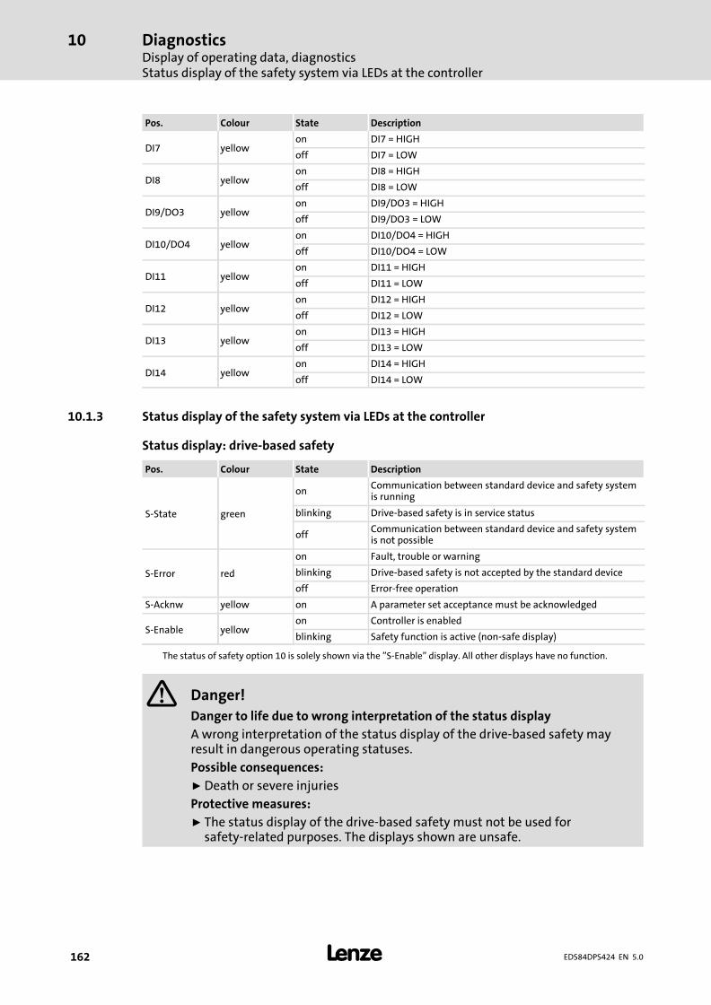
DiagnosticsDisplay of operating data, diagnosticsStatus display of the safety system via LEDs at the controller
10
� 162 EDS84DPS424 EN 5.0
Pos. Colour State Description
DI7 yellowon DI7 = HIGH
off DI7 = LOW
DI8 yellowon DI8 = HIGH
off DI8 = LOW
DI9/DO3 yellowon DI9/DO3 = HIGH
off DI9/DO3 = LOW
DI10/DO4 yellowon DI10/DO4 = HIGH
off DI10/DO4 = LOW
DI11 yellowon DI11 = HIGH
off DI11 = LOW
DI12 yellowon DI12 = HIGH
off DI12 = LOW
DI13 yellowon DI13 = HIGH
off DI13 = LOW
DI14 yellowon DI14 = HIGH
off DI14 = LOW
10.1.3 Status display of the safety system via LEDs at the controller
Status display: drive−based safety
Pos. Colour State Description
S−State green
onCommunication between standard device and safety systemis running
blinking Drive−based safety is in service status
offCommunication between standard device and safety systemis not possible
S−Error red
on Fault, trouble or warning
blinking Drive−based safety is not accepted by the standard device
off Error−free operation
S−Acknw yellow on A parameter set acceptance must be acknowledged
S−Enable yellowon Controller is enabled
blinking Safety function is active (non−safe display)
The status of safety option 10 is solely shown via the "S−Enable" display. All other displays have no function.
� Danger!
Danger to life due to wrong interpretation of the status display
A wrong interpretation of the status display of the drive−based safety mayresult in dangerous operating statuses.
Possible consequences:
ƒ Death or severe injuries
Protective measures:
ƒ The status display of the drive−based safety must not be used forsafety−related purposes. The displays shown are unsafe.
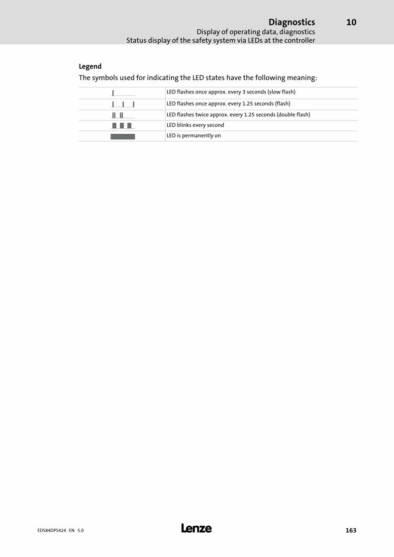
DiagnosticsDisplay of operating data, diagnostics
Status display of the safety system via LEDs at the controller
10
� 163EDS84DPS424 EN 5.0
Legend
The symbols used for indicating the LED states have the following meaning:
LED flashes once approx. every 3 seconds (slow flash)
LED flashes once approx. every 1.25 seconds (flash)
LED flashes twice approx. every 1.25 seconds (double flash)
LED blinks every second
LED is permanently on
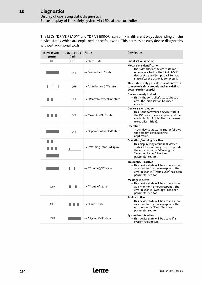
DiagnosticsDisplay of operating data, diagnosticsStatus display of the safety system via LEDs at the controller
10
� 164 EDS84DPS424 EN 5.0
The LEDs "DRIVE READY" and "DRIVE ERROR" can blink in different ways depending on thedevice states which are explained in the following. This permits an easy device diagnosticswithout additional tools.
DRIVE READY(green)
DRIVE ERROR(red)
Status Description
OFF OFF � "Init" state Initialisation is active
OFF � "MotorIdent" state
Motor data identification– The "MotorIdent" device state can
only be reached by the "SwitchON"device state and jumps back to thatstate after the action is completed.
OFF � "SafeTorqueOff" stateThis state is only possible in relation with aconnected safety module and an existingpower section supply!
OFF � "ReadyToSwitchOn" state
Device is ready to start– This is the controller’s state directly
after the initialisation has beencompleted.
OFF � "SwitchedOn" state
Device is switched on– This is the controller’s device state if
the DC bus voltage is applied and thecontroller is still inhibited by the user(controller inhibit).
OFF � "OperationEnabled" state
Operation– In this device state, the motor follows
the setpoint defined in theapplication.
� "Warning" status display
Operation/warning is active– This display may occur in all device
states if a monitoring mode respondsthe error response "Warning" or"Warning locked" has beenparameterised for.
� "TroubleQSP" state
TroubleQSP is active– This device state will be active as soon
as a monitoring mode responds, theerror response "TroubleQSP" has beenparameterised for.
OFF � "Trouble" state
Message is active– This device state will be active as soon
as a monitoring mode responds, theerror response "Message" has beenparameterised for.
OFF � "Fault" state
Fault is active– This device state will be active as soon
as a monitoring mode responds, theerror response "Fault" has beenparameterised for.
OFF � "SystemFail" stateSystem fault is active
– This device state will be active if asystem fault occurs.
DiagnosticsDisplay of operating data, diagnostics
Drive diagnostics via the integrated display
10
� 165EDS84DPS424 EN 5.0
10.1.4 Drive diagnostics via the integrated display
The controllers have an integrated 7−segment display which, depending on the deviceversion, comprises either 4 or 5 characters.
The display has three different modes:
ƒ Automatic display − the parameter saved under status value 1 is displayed when thecontroller is switched on.
ƒ Manual operation display − when the controller is activated during manualoperation.
ƒ Message display − for errors or warnings. This display has the highest priority andoverrides the other two modes.
Operation is carried out via keys T1 and T2.
ƒ T1 − operator button to display the status of lower−level devices (in preparation).
ƒ T2 − operator button used for browsing if several status messages or error messageshave occurred at the same time.
In the case of a device replacement, both keys must be operated to transfer the safeparameters from the memory module to the safety module. Further information on thistopic is provided in the corresponding documentation.
Automatic display
This mode serves to display five preset parameters in a row. Use key T2 to browse theparameters in ascending order. Using the »Engineer«, the user can define which statusvalues are shown in the display. The following status values (Lenze setting) are displayed:
ƒ Status value 1: Motor output frequency in [Hz]
The output frequency is displayed based on the direction of rotation, i.e. CCW rotationis displayed with a minus sign. The display area ranges from − 999 to 999 Hz and has aresolution of 1 Hz.
ƒ Status value 2: Actual current value in [A], resolution 0.1 A
ƒ Status value 3: Device utilisation in [%]
ƒ Status value 4: Motor voltage in [V]
ƒ Status value 5: DC−bus voltage in [V]
Manual operation display (in preparation)
ƒ If the operator button is used to switch the controller over to the manual operationmode, "rc" is displayed.
ƒ If an error is pending during manual operation, the display changes from "rc" to theerror code every 0.5 s. If several errors are pending, they are displayed alternately.
ƒ If the operator button is used to switch over between CCW and CW rotation, themotor output frequency is displayed without sign for CW rotation and with a minussign for CCW rotation.
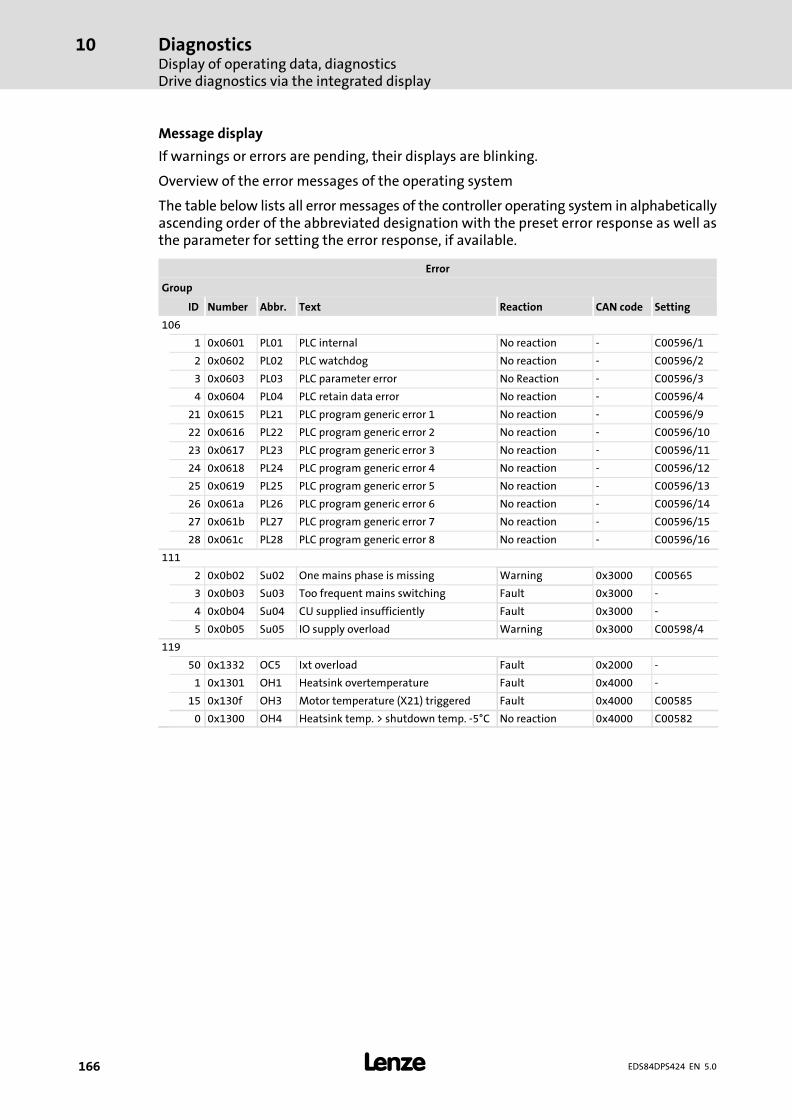
DiagnosticsDisplay of operating data, diagnosticsDrive diagnostics via the integrated display
10
� 166 EDS84DPS424 EN 5.0
Message display
If warnings or errors are pending, their displays are blinking.
Overview of the error messages of the operating system
The table below lists all error messages of the controller operating system in alphabeticallyascending order of the abbreviated designation with the preset error response as well asthe parameter for setting the error response, if available.
Error
Group
ID Number Abbr. Text Reaction CAN code Setting
106
1 0x0601 PL01 PLC internal No reaction − C00596/1
2 0x0602 PL02 PLC watchdog No reaction − C00596/2
3 0x0603 PL03 PLC parameter error No Reaction − C00596/3
4 0x0604 PL04 PLC retain data error No reaction − C00596/4
21 0x0615 PL21 PLC program generic error 1 No reaction − C00596/9
22 0x0616 PL22 PLC program generic error 2 No reaction − C00596/10
23 0x0617 PL23 PLC program generic error 3 No reaction − C00596/11
24 0x0618 PL24 PLC program generic error 4 No reaction − C00596/12
25 0x0619 PL25 PLC program generic error 5 No reaction − C00596/13
26 0x061a PL26 PLC program generic error 6 No reaction − C00596/14
27 0x061b PL27 PLC program generic error 7 No reaction − C00596/15
28 0x061c PL28 PLC program generic error 8 No reaction − C00596/16
111
2 0x0b02 Su02 One mains phase is missing Warning 0x3000 C00565
3 0x0b03 Su03 Too frequent mains switching Fault 0x3000 −
4 0x0b04 Su04 CU supplied insufficiently Fault 0x3000 −
5 0x0b05 Su05 IO supply overload Warning 0x3000 C00598/4
119
50 0x1332 OC5 Ixt overload Fault 0x2000 −
1 0x1301 OH1 Heatsink overtemperature Fault 0x4000 −
15 0x130f OH3 Motor temperature (X21) triggered Fault 0x4000 C00585
0 0x1300 OH4 Heatsink temp. > shutdown temp. −5°C No reaction 0x4000 C00582
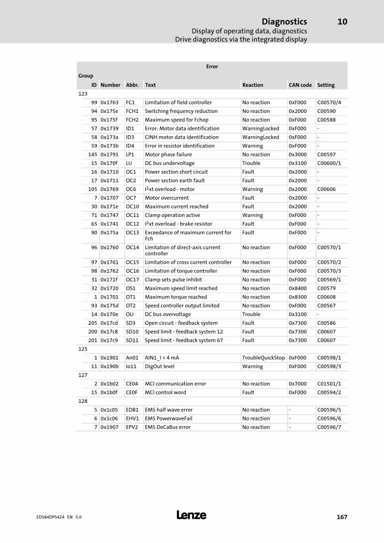
DiagnosticsDisplay of operating data, diagnostics
Drive diagnostics via the integrated display
10
� 167EDS84DPS424 EN 5.0
Error
Group
SettingCAN codeReactionTextAbbr.NumberID
123
99 0x1763 FC1 Limitation of field controller No reaction 0xF000 C00570/4
94 0x175e FCH1 Switching frequency reduction No reaction 0x2000 C00590
95 0x175f FCH2 Maximum speed for Fchop No reaction 0xF000 C00588
57 0x1739 ID1 Error: Motor data identification WarningLocked 0xF000 −
58 0x173a ID3 CINH motor data identification WarningLocked 0xF000 −
59 0x173b ID4 Error in resistor identification Warning 0xF000 −
145 0x1791 LP1 Motor phase failure No reaction 0x3000 C00597
15 0x170f LU DC bus undervoltage Trouble 0x3100 C00600/1
16 0x1710 OC1 Power section short circuit Fault 0x2000 −
17 0x1711 OC2 Power section earth fault Fault 0x2000 −
105 0x1769 OC6 I2xt overload − motor Warning 0x2000 C00606
7 0x1707 OC7 Motor overcurrent Fault 0x2000 −
30 0x171e OC10 Maximum current reached Fault 0x2000 −
71 0x1747 OC11 Clamp operation active Warning 0xF000 −
65 0x1741 OC12 I2xt overload − brake resistor Fault 0xF000 −
90 0x175a OC13 Exceedance of maximum current forFch
Fault 0xF000 −
96 0x1760 OC14 Limitation of direct−axis currentcontroller
No reaction 0xF000 C00570/1
97 0x1761 OC15 Limitation of cross current controller No reaction 0xF000 C00570/2
98 0x1762 OC16 Limitation of torque controller No reaction 0xF000 C00570/3
31 0x171f OC17 Clamp sets pulse inhibit No reaction 0xF000 C00569/1
32 0x1720 OS1 Maximum speed limit reached No reaction 0x8400 C00579
1 0x1701 OT1 Maximum torque reached No reaction 0x8300 C00608
93 0x175d OT2 Speed controller output limited No reaction 0xF000 C00567
14 0x170e OU DC bus overvoltage Trouble 0x3100 −
205 0x17cd SD3 Open circuit − feedback system Fault 0x7300 C00586
200 0x17c8 SD10 Speed limit − feedback system 12 Fault 0x7300 C00607
201 0x17c9 SD11 Speed limit − feedback system 67 Fault 0x7300 C00607
125
1 0x1901 An01 AIN1_I < 4 mA TroubleQuickStop 0xF000 C00598/1
11 0x190b Io11 DigOut level Warning 0xF000 C00598/3
127
2 0x1b02 CE04 MCI communication error No reaction 0x7000 C01501/1
15 0x1b0f CE0F MCI control word Fault 0xF000 C00594/2
128
5 0x1c05 EDB1 EMS half wave error No reaction − C00596/5
6 0x1c06 EHV1 EMS PowerwaveFail No reaction − C00596/6
7 0x1907 EPV2 EMS DeCaBus error No reaction − C00596/7
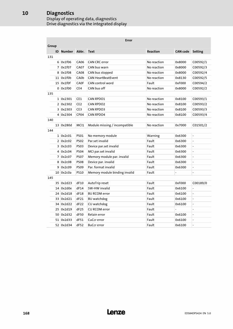
DiagnosticsDisplay of operating data, diagnosticsDrive diagnostics via the integrated display
10
� 168 EDS84DPS424 EN 5.0
Error
Group
SettingCAN codeReactionTextAbbr.NumberID
131
6 0x1f06 CA06 CAN CRC error No reaction 0x8000 C00592/1
7 0x1f07 CA07 CAN bus warn No reaction 0x8000 C00592/3
8 0x1f08 CA08 CAN bus stopped No reaction 0x8000 C00592/4
11 0x1f0b CA0b CAN HeartBeatEvent No reaction 0x8130 C00592/5
15 0x1f0f CA0F CAN control word Fault 0xF000 C00594/2
0 0x1f00 CE4 CAN bus off No reaction 0x8000 C00592/2
135
1 0x2301 CE1 CAN RPDO1 No reaction 0x8100 C00593/1
2 0x2302 CE2 CAN RPDO2 No reaction 0x8100 C00593/2
3 0x2303 CE3 CAN RPDO3 No reaction 0x8100 C00593/3
4 0x2304 CP04 CAN RPDO4 No reaction 0x8100 C00593/4
140
13 0x280d MCI1 Module missing / incompatible No reaction 0x7000 C01501/2
144
1 0x2c01 PS01 No memory module Warning 0x6300 −
2 0x2c02 PS02 Par.set invalid Fault 0x6300 −
3 0x2c03 PS03 Device par.set invalid Fault 0x6300 −
4 0x2c04 PS04 MCI par.set invalid Fault 0x6300 −
7 0x2c07 PS07 Memory module par. invalid Fault 0x6300 −
8 0x2c08 PS08 Device par. invalid Fault 0x6300 −
9 0x2c09 PS09 Par. format invalid Fault 0x6300 −
10 0x2c0a PS10 Memory module binding invalid Fault − −
145
35 0x2d23 dF10 AutoTrip reset Fault 0xF000 C00189/0
14 0x2d0e dF14 SW−HW invalid Fault 0x6100 −
24 0x2d18 dF18 BU RCOM error Fault 0x6100 −
33 0x2d21 dF21 BU watchdog Fault 0x6100 −
34 0x2d22 dF22 CU watchdog Fault 0x6100 −
25 0x2d19 dF25 CU RCOM error Fault − −
50 0x2d32 dF50 Retain error Fault 0x6100 −
51 0x2d33 dF51 CuCcr error Fault 0x6100 −
52 0x2d34 dF52 BuCcr error Fault 0x6100 −
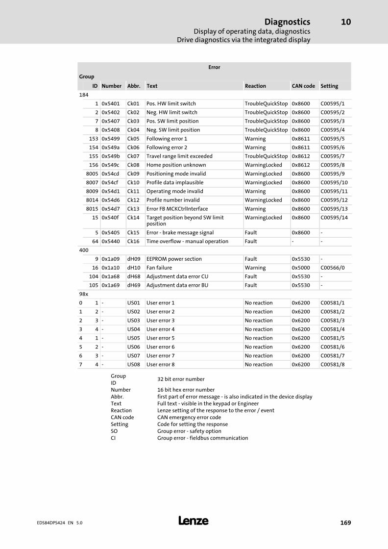
DiagnosticsDisplay of operating data, diagnostics
Drive diagnostics via the integrated display
10
� 169EDS84DPS424 EN 5.0
Error
Group
SettingCAN codeReactionTextAbbr.NumberID
184
1 0x5401 Ck01 Pos. HW limit switch TroubleQuickStop 0x8600 C00595/1
2 0x5402 Ck02 Neg. HW limit switch TroubleQuickStop 0x8600 C00595/2
7 0x5407 Ck03 Pos. SW limit position TroubleQuickStop 0x8600 C00595/3
8 0x5408 Ck04 Neg. SW limit position TroubleQuickStop 0x8600 C00595/4
153 0x5499 Ck05 Following error 1 Warning 0x8611 C00595/5
154 0x549a Ck06 Following error 2 Warning 0x8611 C00595/6
155 0x549b Ck07 Travel range limit exceeded TroubleQuickStop 0x8612 C00595/7
156 0x549c Ck08 Home position unknown WarningLocked 0x8612 C00595/8
8005 0x54cd Ck09 Positioning mode invalid WarningLocked 0x8600 C00595/9
8007 0x54cf Ck10 Profile data implausible WarningLocked 0x8600 C00595/10
8009 0x54d1 Ck11 Operating mode invalid Warning 0x8600 C00595/11
8014 0x54d6 Ck12 Profile number invalid WarningLocked 0x8600 C00595/12
8015 0x54d7 Ck13 Error FB MCKCtrlInterface Warning 0x8600 C00595/13
15 0x540f Ck14 Target position beyond SW limitposition
WarningLocked 0x8600 C00595/14
5 0x5405 Ck15 Error − brake message signal Fault 0x8600 −
64 0x5440 Ck16 Time overflow − manual operation Fault − −
400
9 0x1a09 dH09 EEPROM power section Fault 0x5530 −
16 0x1a10 dH10 Fan failure Warning 0x5000 C00566/0
104 0x1a68 dH68 Adjustment data error CU Fault 0x5530 −
105 0x1a69 dH69 Adjustment data error BU Fault 0x5530 −
98x
0 1 − US01 User error 1 No reaction 0x6200 C00581/1
1 2 − US02 User error 2 No reaction 0x6200 C00581/2
2 3 − US03 User error 3 No reaction 0x6200 C00581/3
3 4 − US04 User error 4 No reaction 0x6200 C00581/4
4 1 − US05 User error 5 No reaction 0x6200 C00581/5
5 2 − US06 User error 6 No reaction 0x6200 C00581/6
6 3 − US07 User error 7 No reaction 0x6200 C00581/7
7 4 − US08 User error 8 No reaction 0x6200 C00581/8
Group32 bit error number
IDNumber 16 bit hex error numberAbbr. first part of error message − is also indicated in the device displayText Full text − visible in the keypad or EngineerReaction Lenze setting of the response to the error / eventCAN code CAN emergency error codeSetting Code for setting the responseSO Group error − safety optionCI Group error − fieldbus communication
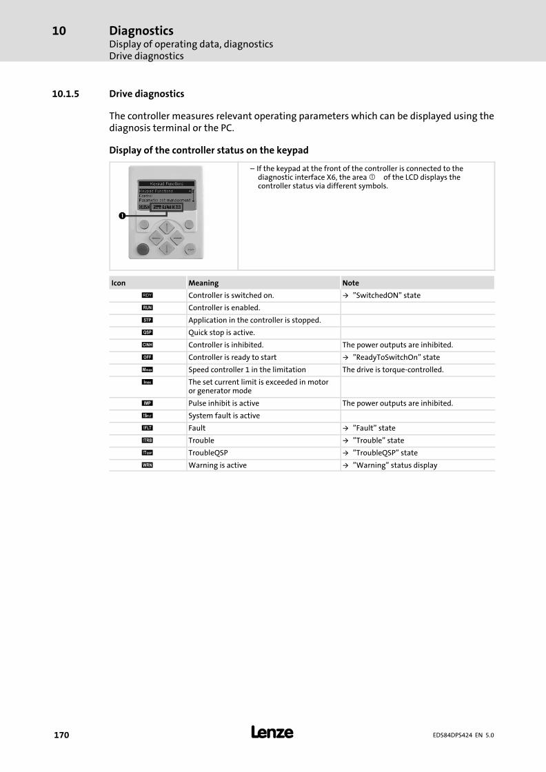
DiagnosticsDisplay of operating data, diagnosticsDrive diagnostics
10
� 170 EDS84DPS424 EN 5.0
10.1.5 Drive diagnostics
The controller measures relevant operating parameters which can be displayed using thediagnosis terminal or the PC.
Display of the controller status on the keypad
– If the keypad at the front of the controller is connected to thediagnostic interface X6, the area � of the LCD displays thecontroller status via different symbols.
Icon Meaning Note
# Controller is switched on. � "SwitchedON" state
$ Controller is enabled.
% Application in the controller is stopped.
& Quick stop is active.
' Controller is inhibited. The power outputs are inhibited.
( Controller is ready to start � "ReadyToSwitchOn" state
) Speed controller 1 in the limitation The drive is torque−controlled.
* The set current limit is exceeded in motoror generator mode
+ Pulse inhibit is active The power outputs are inhibited.
, System fault is active
- Fault � "Fault" state
. Trouble � "Trouble" state
/ TroubleQSP � "TroubleQSP" state
0 Warning is active � "Warning" status display
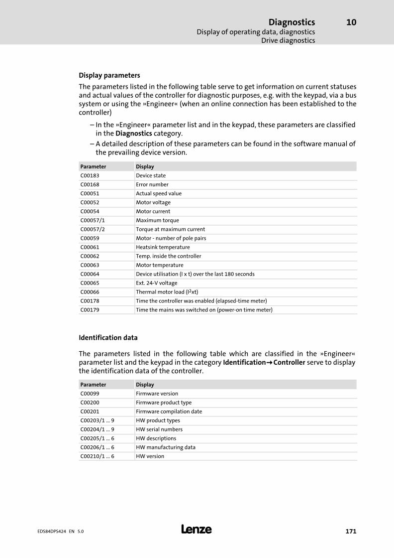
DiagnosticsDisplay of operating data, diagnostics
Drive diagnostics
10
� 171EDS84DPS424 EN 5.0
Display parameters
The parameters listed in the following table serve to get information on current statusesand actual values of the controller for diagnostic purposes, e.g. with the keypad, via a bussystem or using the »Engineer« (when an online connection has been established to thecontroller)
– In the »Engineer« parameter list and in the keypad, these parameters are classifiedin the Diagnostics category.
– A detailed description of these parameters can be found in the software manual ofthe prevailing device version.
Parameter Display
C00183 Device state
C00168 Error number
C00051 Actual speed value
C00052 Motor voltage
C00054 Motor current
C00057/1 Maximum torque
C00057/2 Torque at maximum current
C00059 Motor − number of pole pairs
C00061 Heatsink temperature
C00062 Temp. inside the controller
C00063 Motor temperature
C00064 Device utilisation (I x t) over the last 180 seconds
C00065 Ext. 24−V voltage
C00066 Thermal motor load (I2xt)
C00178 Time the controller was enabled (elapsed−time meter)
C00179 Time the mains was switched on (power−on time meter)
Identification data
The parameters listed in the following table which are classified in the »Engineer«parameter list and the keypad in the category Identification!1!Controller serve to displaythe identification data of the controller.
Parameter Display
C00099 Firmware version
C00200 Firmware product type
C00201 Firmware compilation date
C00203/1 ... 9 HW product types
C00204/1 ... 9 HW serial numbers
C00205/1 ... 6 HW descriptions
C00206/1 ... 6 HW manufacturing data
C00210/1 ... 6 HW version
Safety engineeringIntroduction
11
� 172 EDS84DPS424 EN 5.0
11 Safety engineering
11.1 Introduction
With increasing automation, protection of persons against hazardous movements isbecoming more important. Functional safety describes the measures needed by means ofelectrical or electronic equipment to reduce or remove danger caused by failures.
During normal operation, safety equipment prevents people accessing hazardous areas. Incertain operating modes, e.g. set−up mode, work needs to be carried out in hazardousareas. In these situations the machine operator must be protected by integrated drive andcontrol measures.
Drive−based safety provides the conditions in the controls and drives to optimise the safetyfunctions. Planning and installation expenditure is reduced. In comparison to the use ofstandard safety engineering, drive−based safety increases machine functionality andavailability.
Drive−based safety with L−force | 8400 protec
Unlike control cabinet devices, decentralised drives are frequency inverters which are notlocally mounted but directly attached to the application on site. Due to thisproduct−specific property, they must meet demanding requirements for robustness andclass of protection.
8400 protec controllers are optionally available with drive−based safety.
"Drive−based safety" stands for applied safety functions, which can be used for theprotection of persons working on machines.
The motion functions are continued to be executed by the controller. The drive−basedsafety monitors the safe compliance with the limit values and provides the safe inputs andoutputs. When the limit values are exceeded, the drive−based safety starts the controlfunctions according to EN 60204−1 directly in the controller.
The safety functions are suitable for applications according to IEC 61508 to SIL 3 andachieve a performance level (PL) e and the control category 3 or 4 depending on the safetyoption according to EN ISO 13849−1.
Safety engineeringImportant notes
11
� 173EDS84DPS424 EN 5.0
11.2 Important notes
Application as directed
The controllers of the 8400 protec series that are equipped with drive−based safety mustnot be modified by the user. This concerns the unauthorised exchange or removal of thedrive−based safety.
� Danger!
Danger to life through improper installation
Improper installation of safety engineering systems can cause an uncontrolledstarting action of the drives.
Possible consequences:
ƒ Death or severe injuries
Protective measures:
ƒ Safety engineering systems may only be installed and commissioned byqualified and skilled personnel.
ƒ All control components (switches, relays, PLC, ...) and the control cabinetmust comply with the requirements of ISO 138491 and ISO 13849−2. Thisincludes i.a.:– Switches, relays with at least IP54 enclosure.– Control cabinet with at least IP54 enclosure.– Please refer to ISO 138491 and ISO 13849−2 for all further requirements.
ƒ Wiring must be shielded.
ƒ All safety relevant cables outside the control cabinet must be protected, e.g.by means of a cable duct:– Ensure that no short circuits can occur.– For further measures see EN ISO 13849−2.
ƒ If an external force acts upon the drive axes, additional brakes are required.Please observe that hanging loads are subject to the force of gravity!
� Danger!
When the "safe torque off" (STO) function is used, an "emergencyswitching−off" according to EN 60204 is not possible without additionalmeasures. There is no electrical isolation, no service switch or repair switchbetween motor and controller!
�Emergency switching−off" requires an electrical isolation, e.g. by a centralmains contactor!
Safety engineeringOverview of safety options
11
� 174 EDS84DPS424 EN 5.0
11.3 Overview of safety options
Depending on the device version, the following safety functions are available:
Safety option 10
Due to safety option 10, the following safety functions can be used:
ƒ Safe torque off (STO),formerly: safe standstill
If requested, the safe disconnection of the drive is achieved through:
ƒ Directly connected active sensors
ƒ Passive sensors connected to a safety switching device
The safety functions are suitable for applications according to IEC 61508 to SIL 3 andachieve a performance level (PL) e and the control category 4 according to EN ISO 13849−1.
Safety option 20
Due to safety option 20, the following safety functions can be used:
ƒ Safe torque off (STO),formerly: safe standstill
ƒ Safe stop 1 (SS1)
ƒ Safe stop emergency (SSE)
ƒ Safe operation mode selector (OMS)
ƒ Safe enable switch (ES)
The safe disconnection of the drive is achieved through:
ƒ a higher−level safety PLC via PROFIsafe/PROFINET
ƒ a higher−level safety PLC via PROFIsafe/PROFIBUS
The functions of the safety option must be parameterised via the »Engineer«.
The motion functions are continued to be executed by the controller. The drive−basedsafety monitors the safe compliance with the limit values. When the limit values areexceeded, the drive−based safety starts the control functions according to EN 60204−1directly in the controller.
The safety functions are suitable for applications according to IEC 61508 to SIL 3 andachieve a performance level (PL) e and the control category 3 according to EN ISO 13849−1.
Safety engineeringOverview of safety options
11
� 175EDS84DPS424 EN 5.0
Safety option 30
Due to safety option 30, the following safety functions can be used:
ƒ Safe torque off (STO),formerly: safe standstill
ƒ Safe stop 1 (SS1)
ƒ Safe stop emergency (SSE)
ƒ Safe operation mode selector (OMS)
ƒ Safe enable switch (ES)
The safe disconnection of the drive is achieved through:
ƒ a higher−level safety PLC via PROFIsafe/PROFINET
ƒ connected active or passive sensors
The functions of the safety option must be parameterised via the »Engineer«.
The motion functions are continued to be executed by the controller. The drive−basedsafety monitors the safe compliance with the limit values. When the limit values areexceeded, the drive−based safety starts the control functions according to EN 60204−1directly in the controller.
The safety functions are suitable for applications according to IEC 61508 to SIL 3 andachieve a performance level (PL) e and the control category 3 according to EN ISO 13849−1.
� Further information on functional safety is provided in:
ƒ the 8400 protec manual on drive−based safety
ƒ the 8400 protec software manual on drive−based safety: Parameter setting& configuration
Accessories (overview)Overview
12
� 176 EDS84DPS424 EN 5.0
12 Accessories (overview)
� Note!
You can find additional information on the accessories in the catalogue to thisproduct series.
12.1 Overview
Coordinated accessories for L−force Inverter Drives 8400 protec:
ƒ Lenze system cables
– Motor connection
– Brake resistor connection
– Incremental HTL encoder
ƒ Memory module
ƒ USB−diagnostic adapter E94AZCUS
– Connecting cables EWL007x
ƒ PC system bus adapter EMF2173IBxxx/EMF2177IB
ƒ Diagnosis terminal EZAEBK2001
ƒ Brake resistors ERBMxxxRxxxW/ERBPxxxRxxxW/ERBSxxxRxxxW
ƒ 24−V power supply units EZVxx00−00x
ƒ EMS accessories
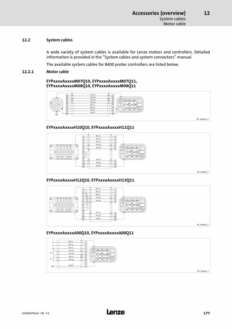
Accessories (overview)System cables
Motor cable
12
� 177EDS84DPS424 EN 5.0
12.2 System cables
A wide variety of system cables is available for Lenze motors and controllers. Detailedinformation is provided in the "System cables and system connectors" manual.
The available system cables for 8400 protec controllers are listed below.
12.2.1 Motor cable
EYPxxxxAxxxxM07Q10, EYPxxxxAxxxxM07Q11,EYPxxxxAxxxxM08Q10, EYPxxxxAxxxxM08Q11
4
1
3
A
B
C
D
1 1
A 5A
4 7
3 3
B 8
C 4
D 6BK (1)
WH (6)
BK (2)
WH (5)
GNYE
BK (3)
WH (8)
WH (7)
16
27
38
4
5
hb_mpamq_1
EYPxxxxAxxxxH10Q10, EYPxxxxAxxxxH11Q11
1 1
2 7
3 3
4 4
5 6
6
7
8
9 5
10 8
1
6
2
7
3
8
4
9
5
10
PE
BK (1)
WH (8)
BK (2)
WH (7)
GNYE
BK (3)
WH (6)
WH (5)
16
27
38
4
5
hb_mpahq_1
EYPxxxxAxxxxH12Q10, EYPxxxxAxxxxH13Q11
1
2
3
4
5
6
7
8
9
10
1
6
2
7
3
8
4
9
5
10
PE
BK (1)
WH (8)
BK (2)
WH (7)
GNYE
BK (3)
WH (6)
WH (5)
1
7
3
4
6
5
8
16
27
38
4
5
hb_mpahq_2
EYPxxxxAxxxxA00Q10, EYPxxxxAxxxxA00Q11
U
V
W
PE
�
16
27
38
4
5
1
2
3
4
5
6
7
8
BK (1)
WH (8)
BK (2)
WH (7)
GNYE
BK (3)
WH (6)
WH (5)
hb_mpaaq_1
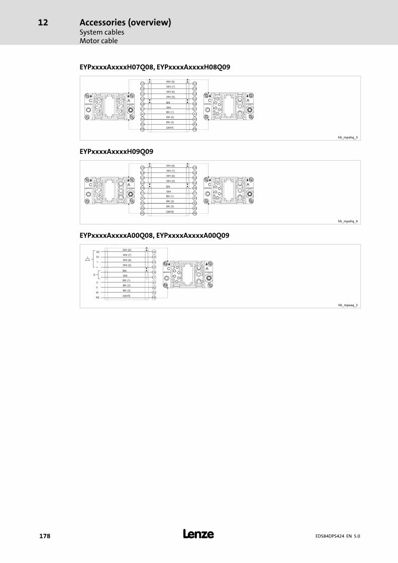
Accessories (overview)System cablesMotor cable
12
� 178 EDS84DPS424 EN 5.0
EYPxxxxAxxxxH07Q08, EYPxxxxAxxxxH08Q09
BK (1)
WH (8)
WH
BN
BK (2)
WH (7)
GNYE
BK (3)
WH (6)
WH (5)
C5
C4
C3
C2
C6
C1
A1
A2
A3
PE
C A1
23
4
6
5
12
3
4
6
5
C5
C4
C3
C2
C6
C1
A1
A2
A3
C A1
2
4
3
5
2
3
1
PE
hb_mpahq_3
EYPxxxxAxxxxH09Q09
BK (1)
WH (8)
WH
BN
BK (2)
WH (7)
GNYE
BK (3)
WH (6)
WH (5)
C5
C4
C3
C2
C6
C1
A1
A2
A3
PE
C A1
23
4
6
5
C5
C4
C3
C2
C6
C1
A1
A2
A3
C A1
2
4
3
5
2
3
1
PE
1
23
hb_mpahq_4
EYPxxxxAxxxxA00Q08, EYPxxxxAxxxxA00Q09
BK (1)
WH
BN
BK (2)
GNYE
BK (3)
C5
C4
C3
C2
C6
C1
A1U
A2V
A3W
PE
C A1
2
4
3
5
2
3
1
PE
WH (8)
WH (7)
WH (6)
WH (5)
S1
S2
~
~
�
hb_mpaaq_2
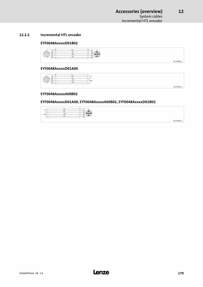
Accessories (overview)System cables
Incremental HTL encoder
12
� 179EDS84DPS424 EN 5.0
12.2.2 Incremental HTL encoder
EYF0048AxxxxD01B02
33
44
22
11BU
YE
OR
WH1
2
34
51
2
34
hb_efadb_1
EYF0048AxxxxD01A00
3
4
2
1BU
YE
OR
WH1
2
34
B
A
Vcc
GND
hb_efada_1
EYF0048AxxxxA00B02
EYF0048AxxxxD01A00, EYF0048AxxxxA00B02, EYF0048AxxxxD01B02
3
4
2
1BU
YE
OR
WH1
2
34
5B
A
Vcc
GND
hb_efaab_1
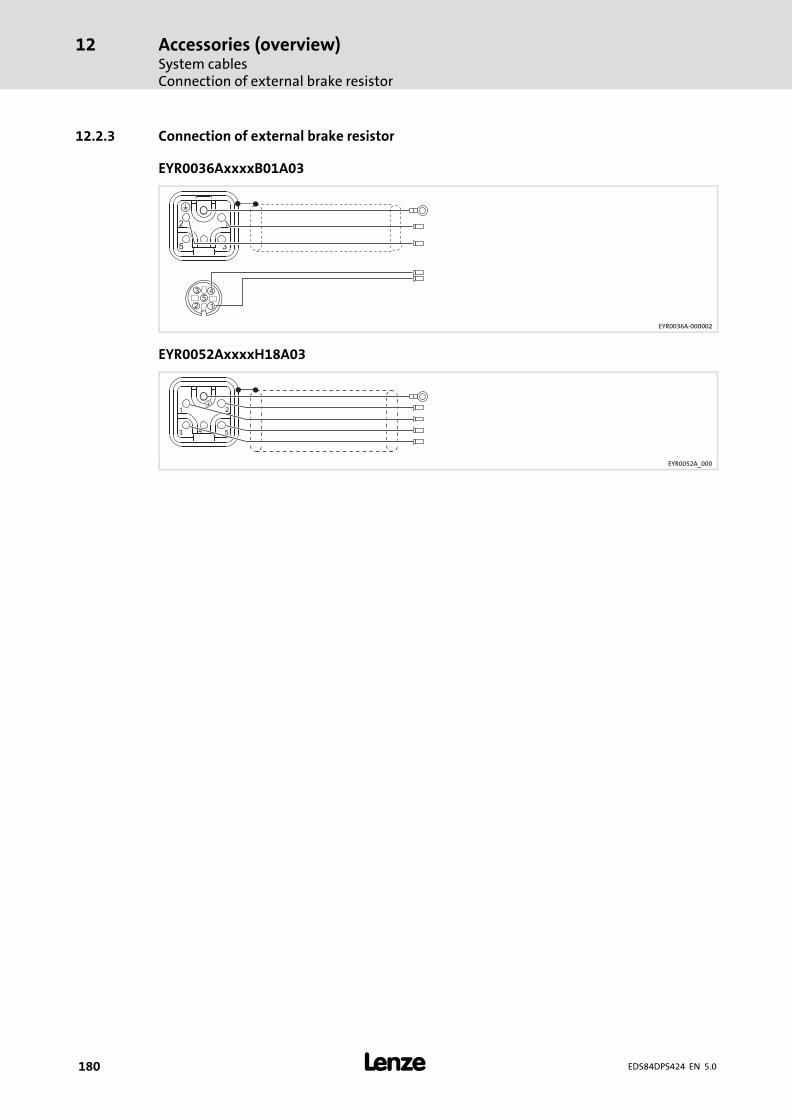
Accessories (overview)System cablesConnection of external brake resistor
12
� 180 EDS84DPS424 EN 5.0
12.2.3 Connection of external brake resistor
EYR0036AxxxxB01A03
2 1
12
3 45
5 3
�
EYR0036A−000002
EYR0052AxxxxH18A03
4
1
53
�2
EYR0052A_000
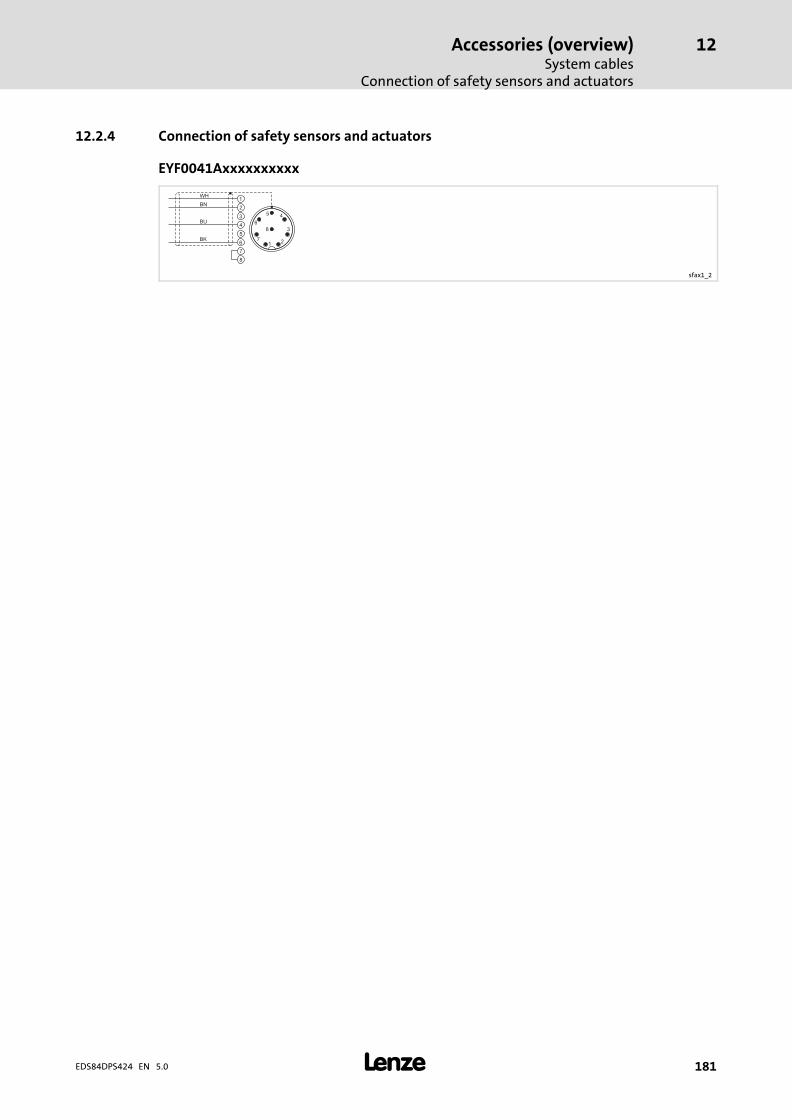
Accessories (overview)System cables
Connection of safety sensors and actuators
12
� 181EDS84DPS424 EN 5.0
12.2.4 Connection of safety sensors and actuators
EYF0041Axxxxxxxxxx
4
7
8
5
3
6
2
1
1 2
3
45
6
7
8
BU
BK
WH
BN
sfax1_2
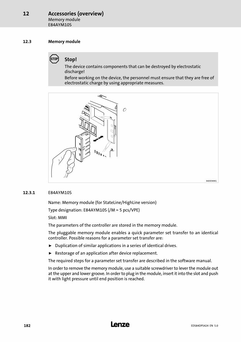
Accessories (overview)Memory moduleE84AYM10S
12
� 182 EDS84DPS424 EN 5.0
12.3 Memory module
Stop!
The device contains components that can be destroyed by electrostaticdischarge!
Before working on the device, the personnel must ensure that they are free ofelectrostatic charge by using appropriate measures.
8400DMM1
12.3.1 E84AYM10S
Name: Memory module (for StateLine/HighLine version)
Type designation: E84AYM10S (/M = 5 pcs/VPE)
Slot: MMI
The parameters of the controller are stored in the memory module.
The pluggable memory module enables a quick parameter set transfer to an identicalcontroller. Possible reasons for a parameter set transfer are:
ƒ Duplication of similar applications in a series of identical drives.
ƒ Restorage of an application after device replacement.
The required steps for a parameter set transfer are described in the software manual.
In order to remove the memory module, use a suitable screwdriver to lever the module outat the upper and lower groove. In order to plug in the module, insert it into the slot and pushit with light pressure until end position is reached.
Accessories (overview)Memory module
E84AYM30S
12
� 183EDS84DPS424 EN 5.0
12.3.2 E84AYM30S
Name: Memory module (for EMS version)
Type designation: E84AYM30S (/M = 5 pcs/VPE)
Slot: MMI
The parameters o the controller are stored in the memory module. Moreover, this modulehas further memory capacity for PLC programs and retain variables.
The pluggable memory module enables a quick parameter set transfer to an identicalcontroller. Possible reasons for a parameter set transfer are:
ƒ Duplication of similar applications in a series of identical drives.
ƒ Restorage of an application after device replacement.
The required steps for a parameter set transfer are described in the software manual.
In order to remove the memory module, use a suitable screwdriver to lever the module outat the upper and lower groove. In order to plug in the module, insert it into the slot and pushit with light pressure until end position is reached.
Accessories (overview)Diagnosis terminal
12
� 184 EDS84DPS424 EN 5.0
12.4 Diagnosis terminal
The X400 diagnosis terminal is a simple means for parameter setting and diagnostics onsite. Clearly structured menus and a plain text menu grant quick data access. The diagnosisterminal is connected to the X70 diagnostic interface (behind the service hatch). Thediagnosis terminal is based on the X400 keypad, extended by a holder and a connectingcable.
Name: Diagnosis terminal X400
Type designation: EZAEBK200x
Slot: X70
Features
ƒ In a robust housing
ƒ Suitable for installation into the control cabinet door
ƒ 2.5 m connecting cable, exchangeable
ƒ Enclosure IP65 is possible for installation into the control cabinet
ƒ Menu−driven diagnostics and parameter setting
ƒ Backlighted graphic display for representing information
ƒ 4 navigation keys, 2 context−sensitive keys
ƒ Adjustable RUN/STOP function
ƒ Hot−plug capable
ƒ Enclosure IP20
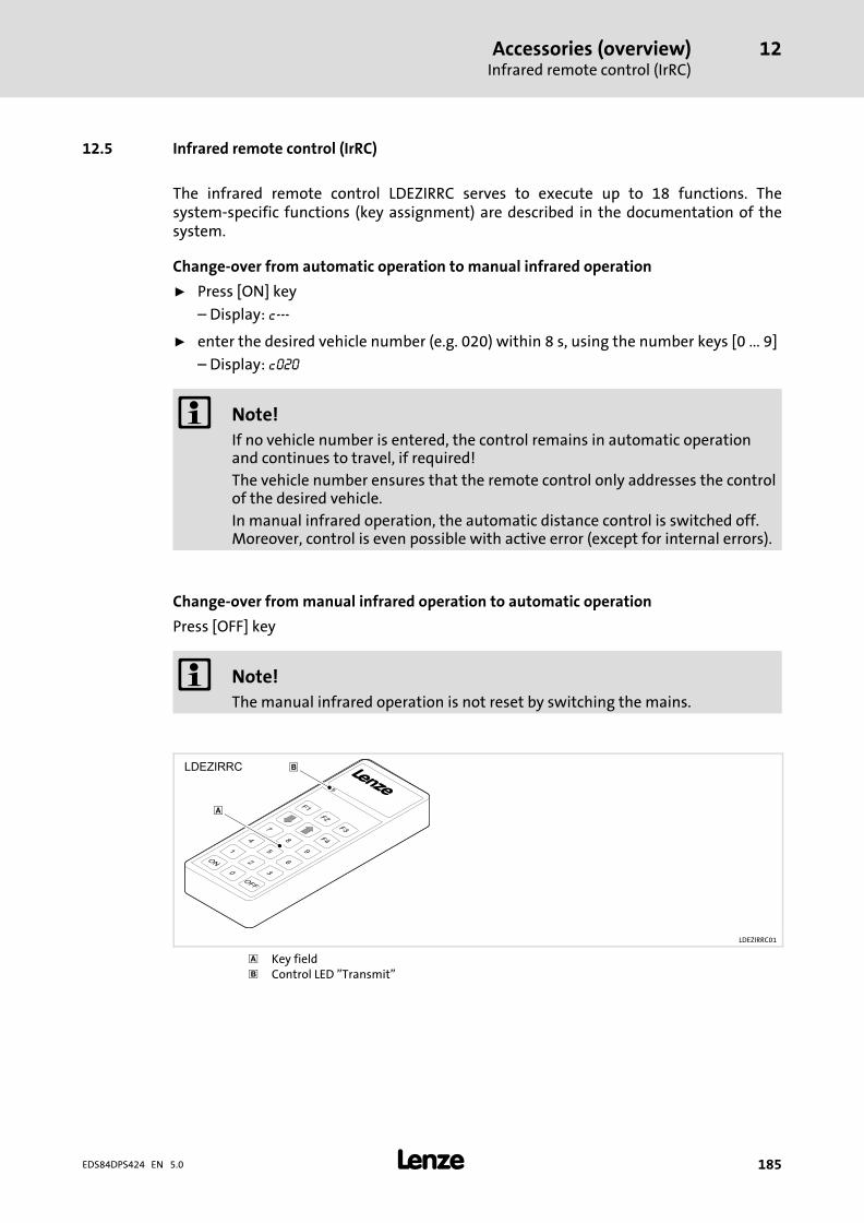
Accessories (overview)Infrared remote control (IrRC)
12
� 185EDS84DPS424 EN 5.0
12.5 Infrared remote control (IrRC)
The infrared remote control LDEZIRRC serves to execute up to 18 functions. Thesystem−specific functions (key assignment) are described in the documentation of thesystem.
Change−over from automatic operation to manual infrared operation
ƒ Press [ON] key
– Display: c−−−
ƒ enter the desired vehicle number (e.g. 020) within 8 s, using the number keys [0 ... 9]
– Display: c020
� Note!
If no vehicle number is entered, the control remains in automatic operationand continues to travel, if required!
The vehicle number ensures that the remote control only addresses the controlof the desired vehicle.
In manual infrared operation, the automatic distance control is switched off.Moreover, control is even possible with active error (except for internal errors).
Change−over from manual infrared operation to automatic operation
Press [OFF] key
� Note!
The manual infrared operation is not reset by switching the mains.
LDEZIRRC01
� Key field Control LED "Transmit"
Accessories (overview)External brake resistors
12
� 186 EDS84DPS424 EN 5.0
12.6 External brake resistors
Assignment of controller − brake resistor
Controller External brake resistor
400 V 500 V
E84Dxxxx7514 ERBS240R300WERBS180R350W
E84Dxxxx1524 ERBS180R350W
E84Dxxxx3024
ERBS047R400W ERBS047R400WE84Dxxxx4024
E84DHxxx7524
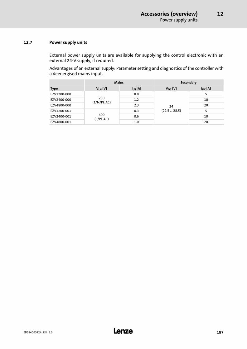
Accessories (overview)Power supply units
12
� 187EDS84DPS424 EN 5.0
12.7 Power supply units
External power supply units are available for supplying the control electronic with anexternal 24−V supply, if required.
Advantages of an external supply: Parameter setting and diagnostics of the controller witha deenergised mains input.
Mains Secondary
Type VLN [V] ILN [A] VDC [V] IDC [A]
EZV1200−000230
(1/N/PE AC)
0.8
24(22.5 ... 28.5)
5
EZV2400−000 1.2 10
EZV4800−000 2.3 20
EZV1200−001400
(3/PE AC)
0.3 5
EZV2400−001 0.6 10
EZV4800−001 1.0 20
Accessories (overview)EMS accessories
12
� 188 EDS84DPS424 EN 5.0
12.8 EMS accessories
ƒ LDEZHMTX − half wave transmission module
Interface module for the half−wave command selection (transmission module) via acontrol bar between the mobile control at the vehicle and the stationary system. Theconnection of up to 8 channels is possible.
ƒ LDEZHMRX − half wave reception module
Interface module for the half−wave feedback (reception module) via a signalling barbetween the mobile control at the vehicle and the stationary system. The connectionof up to 8 channels is possible.
ƒ LDEZPW10238Kxx − Power wave
Communication module with up to 1023 commands for data exchange between thestationary system centre and the mobile control at the vehicle. For communicatingwith the central PLC, PROFIBUS−DP, DeviceNet or INTERBUS CU are available.
ƒ LDEZLDC1Kxx − rail bus local data concentrator
Communication module (master) for data exchange between the system PLC and thebus transfer unit on the rail bus or inductive data transfer. Depending on thecommunication medium, an LDEZLMDC (contact conductor rail bus) or an LDEZLMIDAT(inductive data transfer) interface can be connected.
ƒ LDEZLMDC − rail bus CAN bus driver module
Interface module − CAN bus driver for the rail bus, (implementation TTL −> 50 V DC) forplugging onto the data concentrator (master − bus transfer unit) LDEZLDC1KPB,LDC1KDN, for bidirectional data exchange with mobile control.
ƒ LDEZIRDS − infrared station with fieldbus link
The infrared station is used for bidirectional data exchange between the stationarysystem PLC and the mobile control at the vehicle.
Vehicle−specific process data and maintenance data can be transmitted.Communication is possible with central PLC via PROFINET I/O, (PROFIBUS DP,EtherNet /IP and DeviceNet on request).
ƒ LDEZEXIRD − external infrared module (remote control receiver with LED display)
The external infrared module serves to be connected to a Lenze control systemCCU/ICU series with LDEZDrive PLCC and is an external display as well as an infraredremote control receiver. The connection to the LDEZDPLCC is made via the system bus(CAN) which provides the option to mount it to any position of the vehicle.
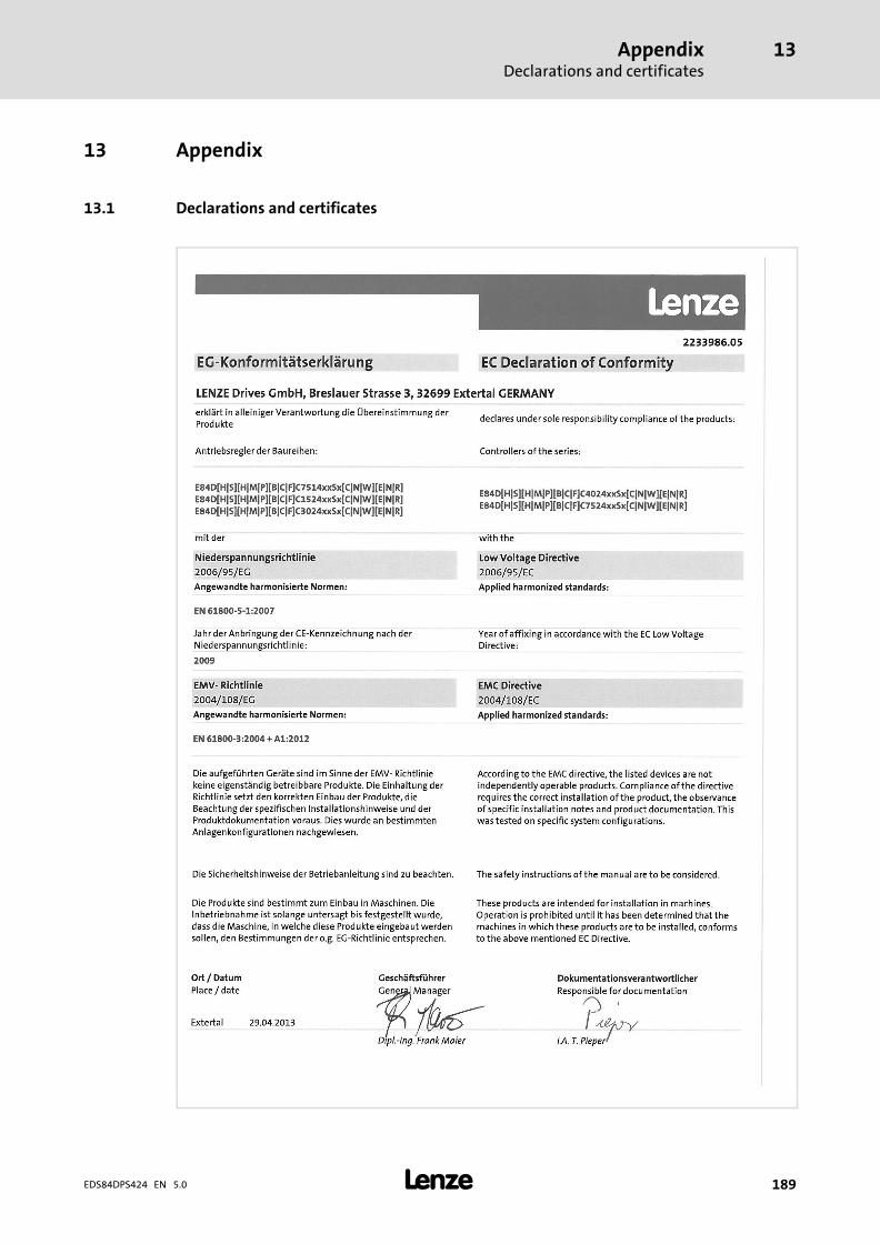
AppendixDeclarations and certificates
13
� 189EDS84DPS424 EN 5.0
13 Appendix
13.1 Declarations and certificates
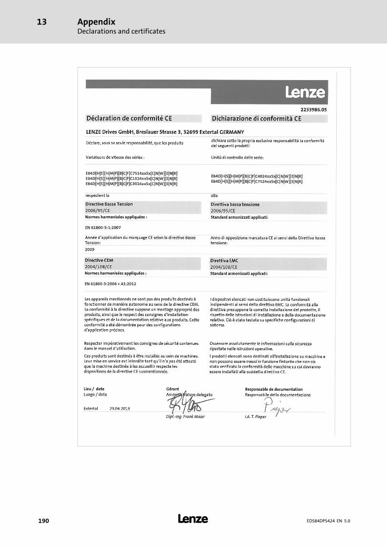
AppendixDeclarations and certificates
13
� 190 EDS84DPS424 EN 5.0
AppendixDeclarations and certificates
13
� 191EDS84DPS424 EN 5.0
AppendixDeclarations and certificates
13
� 192 EDS84DPS424 EN 5.0
AppendixDeclarations and certificates
13
� 193EDS84DPS424 EN 5.0
AppendixDeclarations and certificates
13
� 194 EDS84DPS424 EN 5.0
AppendixTotal index
13
� 195EDS84DPS424 EN 5.0
13.2 Total index
0 ... 97−segment display, 165
AAccessories, 176
− External brake resistor, 151
Ambient conditions
− climatic, 41
− mechanical, 41
Analog input, 93
Analog inputs, 66
Application as directed, 173
Application, as directed, 173
Automatic display, 165
BBasic insulation, 9
Brake resistor
− Selection, 152
− Wiring, 153
Braking, 148
Braking operation, 148
− DC injection brake DCB, 148
− Inverter motor brake, 149
− Stopping of the ramp function generator, 149
− With external brake resistor, 151
− without additional measures, 148
CCable
− For control connections, 82, 114
− for the motor connection, 81, 113, 177
Cables
− cross−sections, 50, 53
− fuses, 50, 53
CAN on board, 101
CAN port, 27
CANopen, 101, 137
CANopen master PLC, 137
certificates, 189
Commissioning, 138
− before initial switch−on, 139
Commissioning steps, 144, 146
Concepts, Mains connection, 30
Configuration, Display functions, 159
Connection, safety sensors and actuators, 181
Contactors, in the motor cable, 19
Control cable, 82, 114
Control terminals, 64, 92, 127
Control voltage, 61
Ddeclarations, 189
Definition of notes used, 12
Definitions, Terms, 9
Device protection, 19, 74, 106, 182
Diagnosis terminal, 184
Diagnostics, 92, 127, 159
Digital inputs, 64, 95, 128
− StateLine C, connection of an HTL incremental encoder,96, 130
Digital outputs, 65, 95, 128
Display
− 7−segment, 165
− operating status, 159
Display functions, 159
Disposal, 15
Double insulation, 9
Drive behaviour, Influence of the motor cable length, 77,109
EElectrical installation
− EMS, 105
− HighLine/StateLine, 73
EMC, what to do in case of interferences, 85, 117
EMS, 23, 26, 45, 60, 64, 65, 67
− extensions, 28, 161
− interfaces, 67
− mains connection concepts, 35
EN 61000−3−2, 43
Enclosure, 40
Extensions, EMS, 28, 161
FFree space, 42
AppendixTotal index
13
�196 EDS84DPS424 EN 5.0
Functional insulation, 9
Fuses, 50, 53
− operation with rated power, 400 V (UL), 50, 53
GGeneral data, 39
HHalf−wave system, technical data, 45
Harmonic currents, limitation according to EN 61000−3−2,43
Holding brake, 9
IIdentification, 21
Infrared
− interface, 29
− remote control, 28
Infrared remote control (IrRC), 185
Installation, electrical
− EMS, 105
− HighLine/StateLine, 73
Installation, mechanical, 70
Integrated display, 165
Interface
− CAN, 27
− IrDA, 29
Interfaces, EMS, 67
Interferences, eliminating EMC interferences, 85, 117
IrDA, 29
IRRC, 66
IrRC, 28
LLED display, 159
LEDs, 159
− safety system, 162
Legal regulations, 173
MMains connection, Concepts, 30
Mains connection concept
− DECA bus, 37
− half wave (coded), 35
− inductive, 38
− Power wave, 36
Mains connection concepts, EMS, 35
Mains current, 48, 51
Manual operation display, 165
Mechanical installation, 70
Memory module, 182
− E84AYM10S, 182
− E84AYM30S, 183
Message display, 166
Motor cable, 81, 113, 177
− capacitance per unit length, 42
− contactors in the, 19
− Influence of the length, 77, 109
− length, 41
− requirements, 42
Motor end, switching on the, 19
Motor holding brake, 9
Motor power, typical, 48, 51
Motor protection, 19
Mounting clearance, 72
Mounting place, 42
Mounting position, 42
NNameplate, 21
Noise emission, 43
Noise immunity, 43
Notes, definition, 12
OOperating conditions, 41
− ambient conditionsclimatic, 41mechanical, 41
Operating status, display, 159
Operation, Overcurrent, 56
Output power, 48, 51
Overspeeds, 19
AppendixTotal index
13
� 197EDS84DPS424 EN 5.0
Overview
− Accessories, 176
− standard devices, 25
− terminals, 59
PPollution, 41
Power bus, 32
Power system, 41
Product description, 20
Protection of persons, 19
Protective insulation of control circuits, 40
Protective measures, 40
QQuick commissioning
− with keypad control, 144
− with terminal control, 146
RReinforced insulation, 9
Remote control
− IRRC, 66
− IrRC, 28
Requirements, motor cable, 42
Residual hazards, 19
Rocker switch, 141
RS422 PLC, 133, 135
RS485 PLC, 133, 134
SSafety, safety engineering, 172
Safety engineering, 172
Safety instructions, 13
− definition, 12
− layout, 12
Safety sensors and actuators, connection, 181
Safety system
− Safety option 10, 174
− Safety option 20, 174
− Safety option 30, 175
− Safety options, overview, 174
Site altitude, 41
Spring−applied brake, 9
Supply conditions, 41
− mains, 41
− motor, 41
Supply voltage
− 24 V external, 62
− 24 V internal, 61
Switch−on, check before initial switch−on, 139
Switching on the motor side, 19
Synchronous serial interface (SSI), 66, 98, 132
TTechnical data, 39
− General data, 39
− IRDA, 67
− IRRC, 66
− Operating conditions, 41
Terminals, 59
Terms
− Controller, 9
− definitions, 9
− Drive, 9
Total index, 195
Type code, finding, 21
VValidity, documentation, 7
WWiring, Brake resistor, 153
XX34, 67
X45, 64
X46, 64
X47, 64
X48, 64
X81, 67
X82, 67

� 3© 10/2013
� Lenze Drives GmbHPostfach 10 13 52D−31763 HamelnGermany
Service Lenze Service GmbHBreslauer Straße 3D−32699 ExtertalGermany
� +49�(0)51�54�/ 82−0 � 00�80�00�/ 24�4�68�77 (24 h helpline)
� +49�(0)51�54�/ 82−28 00 � +49�(0)51�54�/ 82−11 12
� [email protected] � [email protected]
� www.Lenze.com
EDS84DPS424 � .M^h � EN � 5.0 � TD15
10 9 8 7 6 5 4 3 2 1