handbook building products ltd
TRANSCRIPT

Installation Guide&Product Handbook
APRIL 2005PLUM G9
POLYPIPEBUILDING
PRODUCTS LTD
COLD WATERSUPPLY SYSTEMS
incorporating Compression, Push-fit and Electrofusion Fittings
HOT & COLD PLUMBING& HEATING SYSTEM
UNDERFLOOR CENTRALHEATING SYSTEM
www.polyplumb.co.uk
www.ufch.com
www.polypipe.com/bp
2
CONTENTS
Polyplumb Hot & Cold Plumbing & Heating System 5System Approvals and Guarantee .............................................. 6Jointing and Dismantling ............................................................ 8Connection to other Materials .................................................... 10Recommendations for Gas, Oil, Compressed Air
Solid Fuel and Solar Heatings Systems .................................. 10Connection to other Equipment .................................................. 11Quick Fixes and Helpful Hints .................................................... 11Pipe Selection.............................................................................. 12Pipe Installation .......................................................................... 12System Design ............................................................................ 13Manifold System.......................................................................... 14/19Handling and Storage.................................................................. 22Polyplumb Pipe.......................................................................... 24Polyplumb Fittings .................................................................... 25Polyplumb Manifold System .................................................... 34Polyplumb Ancillaries .............................................................. 36Polyplumb Pipe Insulation ...................................................... 40
Advisory Service.......................................................................... 43Solid Floor System ...................................................................... 44Solid Floor System Design .......................................................... 45Solid Floor System Installation.................................................... 46Suspended Floor System ............................................................ 47Suspended Floor System Design ................................................ 48Suspended Floor System Installation.......................................... 49Floating Floor System.................................................................. 50Floating Floor System Design...................................................... 51Floating Floor System Installation .............................................. 52Room Air Temperature Control .................................................... 53Water Temperature Control.......................................................... 55Zonal Regulation Unit .................................................................. 58Polyplumb UFCH Pipe and Fittings.......................................... 60Manifold and Control Products.................................................... 62
(See Guarantee limitations on page 7)
Polyplumb Underfloor Central Heating System 42

3
CONTENTS
System Approvals .............................................................................. 67
Handling and Storage ........................................................................ 68
Blue and Black Polyethylene Pipe ................................................ 70
Polysure Pipe .................................................................................... 72
Jointing Instructions .......................................................................... 74
Polyfast Compression Fittings
System Approvals .............................................................................. 77
Jointing Instructions .......................................................................... 78
Polyfast Fittings .............................................................................. 86
Overlay System
Overlay System .................................................................................. 95
Overlay Installation Instructions ........................................................ 96
Overlay Product Range ...................................................................... 100
Adaptors for Polyfast and Push-fit
to other pipework
Adaptor Sets .................................................................................... 105
Electrofusion Fittings
Jointing Instructions .......................................................................... 109
Electrofusion Fittings ...................................................................... 110
Cold Water Supply System 66
104
108
94
76

POLYPLUMB SYSTEM

5
Polyplumb is an integrated flexible plumbing systemincorporating polybutylene pipes and acomplementary range of push-fit fittings for use in hotand cold water supply and central heatinginstallations.
The Polyplumb System is available in 10mm, 15mm,22mm and 28mm diameter pipe and fittings.
The Polyplumb system combines ease of installationwith long term performance benefits such as beingcorrosion and scale free and offering silent operation.Polyplumb fittings are designed to accept bothcopper and polybutylene pipes allowing installers theflexibility to incorporate rigid pipes where necessary.
SYSTEM BENEFITSThe use of Polybutylene pipe in the Polyplumb systemoffers installers both ease of handling, due to greater pipe flexibility, and a higherdesign life safety factor than alternative plastics pipe materials.
The Polyplumb system is also safer and quicker to install, and requires fewer jointsthan rigid pipe systems, as jointing does not require the useof solvents, solder or naked flames. When installed Polyplumb is more resistant toimpact damage and pipe freeze bursts than rigid pipe systems.
Polyplumb should not be used for the conveyance of gas, oil or compressed air.
P.B.P.S.A.Polypipe Building Products Ltd is a member of the Polybutylene PipingSystems Association which is a recognised association of companieswhose aim is to promote the features, benefits and best practice
installation techniques of Polybutylene pipe systems as well as providing a wide rangeof technical information and support. The P.B.P.S.A. web site can be found atwww.PBPSA.com.
This document should be read in conjunction with all other documentation suppliedwith Polyplumb products. If in doubt, ask!

6
APPLICATIONS - The Polyplumb system is suitable for use in hot and coldwater supply, in radiator central heating systems, and in underfloor centralheating systems. See Design & Installation Guide (UFH 3) for further details.
PERFORMANCE - The system is suitable for use in working applications up to12 bar / 20˚C (6 bar / 90˚C).
STANDARDSMANUFACTURING QUALITY ASSURANCE - in accordancewith BS EN ISO 9002 (BSI reg. firm Certificate FM00318).
INSTALLATION STANDARD - to follow the recommendations of BS5955 - PART 8 2001 Plastic pipework (Thermoplastic Materials).
SYSTEM APPROVALS
BRITISH STANDARD Class S rated to BS7291 Part 1 andKitemark Licence Number 38148 to BS7291 part 2.
WRAS Listed in the WRAS Water Fittings and MaterialsDirectory.
KIWA/KOMO Certificate numbers K14341, 14342 and 14343.BBA Polyplumb polybutylene barrier pipe, fittings, accessoriesand underfloor central heating systems are covered by BBACertificate No 00/3699.
BRITISH GAS - has accepted the Polypipe “Polyplumb” Class S polybutylenebarrier pipe system as being acceptable for open vented and sealed centralheating systems and is eligible for acceptance onto Three Star Central HeatingSystem Cover. NOTE: British Gas do not accept Polyplumb Standard Pipes aspart of the 3 star central heating service contract.
BARRIER PIPES - Tested to DIN 4726 and DIN 4727 giving an oxygenpermeability less than the value of 0·1g (m3d) specified in DIN 4726.
GASES - The Polyplumb system is not suitable for the transportation of gases.
WATER - Polyplumb pipe and fittings are resistant to the build-up of scale.Short term chlorination for disinfection of supply pipe work and normal levelsof chlorine in UK domestic water supplies will not have an adverse effect onPolyplumb. Polyplumb is not suitable however for systems that carry a highconcentration of chlorine, eg supplies to swimming pools.
FM00318

7
Polypipe Guarantees for 25 years against defects inmaterials or manufacture of the Polyplumb hot and cold
water supply and Polyplumb heating system, from thedate of purchase. This guarantee excludes Manifold and
Control products detailed on pages 58, 59 and 60. Thisguarantee only applies if the system is installed in
accordance with the manufacturers recommendations containedwithin this Installer Guide, The Design & Installation Guide and
all other Polyplumb installation documents and is used in anormal domestic operation.
25 Years Guarantee
LIGHT - Polyplumb pipe and fittings should be protected from UV light. Standard decoratingpaints form adequate protection. Polyplumb pipe insulation forms adequate protection for externaluse. Polyplumb is delivered in light protective packaging.
THERMAL - Polybutylene has low thermal conductivity. Its co-efficient of thermal expansion is1.3 x 10-4 m/m˚C. It accommodates expansion by its natural flexibility.
ACOUSTIC - The Polyplumb system gives better performance than rigid pipe systems in termsof low noise transmission and low water hammer effect.
ELECTRICAL - As Polyplumb pipe does not conduct electricity, installations generally requireless equipotential bonding than metal systems. Both the IEE and the IoP give guidance on theearth bonding requirements of plastic pipe systems. Where Polyplumb breaks the continuity ofexisting metal pipe which may be used for earthing or bonding this continuity should bereinstated by affixing permanent earth clips and a section of earth cable between the ends of thecopper pipe.
COMPATIBILITY - The Polyplumb system connects to rigid pipe systems. For details ofcompatibility with specific building materials, eg filler foam, wood worm treatments, pleaseconsult the Polyplumb hotline on 01709 770000. Polyplumb pipes and fittings can be paintedusing emulsion or undercoat and gloss. Cellulose based paints, strippers or thinners must not beused.
MAINTENANCE - None required other than checks on inhibitor level in heatingsystems.

There are six stages to successfully jointing the Polyplumb system.
1a. Cutting Polyplumb pipeAlways use one of the approved pipe cutters (Code PB777 orPB778).A slight rotation of the pipe when cutting will help make theoperation easier. Never use a hacksaw. Wherever possible, cuton a depth insertion mark, these “K” shaped marks are equallyspaced along the pipe and indicate the depth required for fullinsertion in to a Polyplumb socket fitting.
1b. Cutting Copper Pipe for insertion in aPolyplumb fittingWherever possible, use a rotational pipe cutter when cuttingcopper pipe. Ensure that all cut ends have a rounded lead in,with burrs removed. Never use a hacksaw. You will need tomark the depthinsertion on thepipe, the insertiondepths are shownin the table.
2. Use of pipe stiffenerPipe stiffeners are an integral part of the joint when usingPolyplumb pipe with either Polyplumb fittings or compressionfittings and need to be fully inserted in to the pipe end. Theyare not required when using copper pipe.
3. Visual check of fitting & fitting componentsAlthough every single socket is visually checked during themanufacturing process to ensure that all components are
present and in the correct order, a further visual check is recommended astampering by others can take place on site or during distribution. The capshould be hand tight only. Caution - Do not insert fingers into the Polyplumbfittings, as the grab ring is sharp and designed to grip.Note: Components shown in dismantling section.
4. Insert pipe fully into fittingThe pipe should be inserted into the fitting to full socket depth such that theinsertion depth mark aligns with the outer end of the cap nut on the fitting.
5. Grab ring checkA quick tug on the pipe will confirm that the pipe is inserted past the grabring and that a grab ring was present in the fitting. It does not howeverensure that the pipe is fully inserted as this can only be confirmed by usingthe depth insertion mark.
8
Jointing and Dismantling
Pipe diameter (mm) 10 15 22 28
Insertion Depth (mm) 22 27 30 35

9
6. Avoidance of Re-jointing - WARNING!On no account should a pipe be removed from a jointed Polyplumb fitting byremoving the cap-nut and withdrawing the pipe end complete with all thesocket components from the fitting to be rejointed without removing andreplacing the grab-ring into the fitting and re-making the joint in accordancewith the normal Polyplumb jointing procedure.If the pipe end complete with all the socket components is subsequently re-jointed into the body of a fitting, there is a risk that the outer edge of thegrab-ring could catch on the outer end or the inside surface of the socket ofthe fitting which forces the grab-ring into an angled position on the pipe.Forcing the grab-ring into an angled position on the pipe in this way,seriously damages the grab-ring teeth and will reduce the pull-out performaceof the joint when subjected to pressure, such that premature failure willalmost certainly occur.
Dismantling the Joint
Polyplumb fittings must not be dismantled for any reason priorto jointing.
Procedure for using the component pack of spares.
1. If it is necessary to remove a jointed pipe from a fitting, the cap-nutshould be unscrewed and the pipe with all the socket components presenton the pipe end should be pulled out of the socket of the fitting. The pipeend complete with all the socket components should be cut off anddiscarded. A complete component pack of socket spares should be fittedto the socket as described below and pipe jointing should be carried outas described left.
2. The component pack(Code: PB95) is suppliedas a cap-nut with all thesocket components presentin the correct order andretained by a self adhesivesticker.
3. Completely remove theadhesive sticker, ensuringthat the socket componentsremain within the cap-nut.
4. Without removing any of the socket components from the cap-nut,introduce the cap-nut and socket components to the socket of the fittingand tighten up the cap-nut by hand ensuring that the components enterthe socket without snagging.
5. Carry out a visual check to ensure that all socket components are presentin the correct order as shown in the diagram and that the rubber ’O’-ringis lubricated. If in doubt, the ‘O’-ring should be re-lubricated usingPolyplumb silicone lubricant.
6. Carry out pipe jointing as described left.
Retaining Cap
Pipe Stiffener
Spacer28mm only
Spacer
“O“ring
Spacer Washer
Grab ring

10
Connections to Other materialsConnection to Imperial CopperImperial 3/4” Copper pipe is of significantly different size to its metric22mm counterpart and therefore requires a diffferent ‘O’ ring to thatsupplied in the 22mm fitting. The 22mm ‘O’ ring should be replaced with a3/4” ‘O’ ring PB9034. Standard 15mm fittings can be connected toImperial 1/2” copper pipe, and 28mm fittings can be connected to 1”copper pipe.Connection to Irish copper pipeIrish copper pipe to IS238:1980 can be connected to Polyplumb fittingswhich incorporate the 3⁄4” or 1” adaptor set. Using a standard 22mm or28mm Polyplumb fitting, remove the nut and socket components anddiscard. Replace these parts with the relevant adaptor set, 3⁄4” - PB7034 or1” - PB701. The adaptor sets are distinguishable by the black cap nut.Connection to Chrome plated and Stainless steel pipeworkWhere it is necessary to connect to either chrome plated or stainless steelpipework, for instance to exposed pipework in shower areas, thecompression adaptor PB7115 (15mm) or PB7122 (22mm) can provide atransition fitting.Connections close to capillary fittingsCapillary fittings should preferably be completed prior to the use ofPolyplumb fitting. Where this is not possible, care should be taken toensure that flux or solder does not come into contact with Polyplumb pipesor fittings. A damp cloth should be wrapped around the copper pipe closeto the nearest Polyplumb pipe or fitting to ensure against damage byconductive heat. Pipework should be flushed to clear flux before active use.Connection to Incoming cold water supply (MDPE)A range of one piece adaptors are available to connect directly from20mm, 25mm, and 32mm MDPE pipe to 15mm, 22mm and 28mmPolyplumb in both Polyfast (compression MDPE) x Polyplumb and Push-fit(Push-fit MDPE) x Polyplumb. All include a MDPE 12 bar plastic Stiffener,alternatively a range of valves (MDPE x Polyplumb) is available.
Recommendations for Gas, Oil, Compressed Air,Solid Fuel and Solar Heating systemsThe Polyplumb system is suitable for domestic plumbing and heatingsystems. Polyplumb pipes and fittings must not be used for gas and oilsupply pipework or compressed air pipework.Polyplumb pipes and fittings must not be used for solar heating systems.Polyplumb pipes and fittings must not be used for primary or gravitycircuits from solid fuel back boilers.In all the above instances metallic pipework should be installed.

Connections to Other EquipmentBOILERS. Polyplumb pipe should only be connected to gas boilers wherethe pipe connection is outside the boiler casing and where the boilerincorporates a high limit thermostat and pump over-run facility. The pipeconnections should be 350mm from the heat source. In all other situations,a section of metal pipe should be at least 1m in length.
CYLINDERS. Polyplumb pipe can be connected directly to cylinders usingthe cylinder union PB4122. All Polyplumb pipework in the cylindercupboard should be from cut lengths rather than coils and should beclipped to a pipe board rather than the wall using screw clips at 300mmcentres. Pipe clip spacers (PB24**) should be used to achieve crossoverswhere necessary.
SANITARY APPLIANCES. A full range of tap connectors is available toconnect Polyplumb to sanitary appliances. As thePolyplumb system does not require heat to make ajoint, the tap connectors can be connected to thesanitary appliance prior to installation of the sanitaryware itself. Installers need only make a push fitconnection, which can be advantageous in tightlocations. Spigot elbows (PB10**) can be used toconnect directly into shower mixers where thepipework is concealed.
RADIATORS. The Radiator Connector Bend “RCB”provides installers with an attractive method ofconnecting 10mm or 15mm Polyplumb pipe fromwalls or floors to radiators. The rigid white 100mm x150mm bend can be cut to length and connectsdirectly to Polyplumb fittings and radiator valves andrequires pipe stiffeners in each end.
Quick Fixes and Helpful HintsWith well over 200 products in the range the Polyplumb system has afitting for almost every eventuality. Innovative products such as the RadiatorConnector Bend (PB39**), Hand Tighten Tap Connectors (PB27**) andFlexible Hose Tap Connectors (PB68**) provide the installer with costeffective, quick and easy to fit solutions which allow hassle freemaintainance. Recent additions to the range include the 1/2” x 3/8”Reducing Bush (Product Code PB3415) which adapts a 3/8” thread usedon taps and cistern valves to 1/2” threaded tap connector to give a neatunobtrusive connection without the need for excess fittings and SwivelService Valves (PB6515 and PB6615) which are ideal for connecting totaps and cisterns where a method of isolation is required.
11

12
Pipe SelectionCut length or “Plumb straight”Although “Plumb Straight” Coiled pipe is designed to effectively straightenwhen un-coiled, where the visual appearance of pipe is important, i.e.short visible sections of 22mm pipe or cylinder cupboards, straight pipemay be preferred. Note: Polyplumb pipe is not recommended for longpermanently exposed runs of pipe where appearance is important. Bothstraight and coiled pipes are flexible.Standard or BarrierBarrier pipe is a requirement of British Gas and musttherefore be used for heating services which may beadopted for their 3 star warranty. Standard pipe can be used forall domestic water and heating installations which are not to be adoptedby British Gas. Polypipe however recommend that corrosion inhibitors areintroduced to and maintained in all heating systems whether they beinstalled in standard or barrier pipe.
Pipework InstallationMinimum bending radiusThe minimum bending radius of unsupportedPolyplumb pipe is 12 times the pipe diameter. Bends can either be supported at each end of thebends using pipe clips where possible. Alternatively,bends can be supported by a bend former (PB6315or PB6322) where only one screw hole is required,and the minimum bend radius is 8 times thediameter. (see table below)
Pipe CablingThe main benefit of using Polyplumb is that the pipeflexibility allows pipe to be cabled through the fabricof the building offering the following advantages.
New Build1. Allows 1st floors to be laid before plumbing is
installed. Plumbing can be installed through holesdrilled in joists.
2. Site safety is enhanced as pipework can thereforebe installed from below.
Pipe diameter (mm) 10 15 22 28
Unsupported Minimum Bend Radius 120 180 264 336
Supported Minimum Bend Radius 80 120 176 224
0·07 x Span to 0·25 x Span
0·25 x Span to 0·4 x Span
SPAN
Position of Notches & Holes

3. Post installation repair work is reduced, as expansion noise due totrapped pipes does not occur, and leaks due to nailed pipes are avoided.
Alterations to existing systems
1. Less disruption to property as floors and carpetsmay not have to be removed in some rooms.
2. Kinder to building structure, as existing joistsmay not allow further notching.
3. Pipes can be cabled around existingobstructions.
4. Safety is enhanced as no naked flames arerequired.
Polyplumb pipe provides installers with theflexibility of installing pipes through both holes andnotches in joists, choosing the most appropriate method. BuildingRegulations provide instructions on the drilling and notching of floor joists.These requirements are shown above.
Pipe SupportsAll Polyplumb pipes should be correctlysupported using either nail-in (PB22**),snap-fit (PB23**) or bulldog (PB21**) clips.Where required spacer pieces are availablefor the snap-fit clips (PB24**). All valvesshould also be correctly supported toprevent unnecessary strain on the pipework.
System DesignAlthough Polyplumb can be used in exactly thesame way as rigid systems, the flexibility of the pipeallows more design options which may benefit theinstaller, the building, or during future maintenance.The general theory of designing water systems inPolyplumb is to use the flexibility of the pipe to itsbest advantage and therefore using fewer fittings.This not only ensures the most cost-effective use ofthe Polyplumb system but also allows fewer jointsand hence improved flow around changes ofdirection. The flexibility of the pipe allows jointingto be made in fewer locations and joint locationscan more easily be made accessible.
13
Notch depth =0·125 x joist depth
e.g. 21·8mmDepth
e.g. 175mm
Sizes of Notches & Holes
Holes 3 diametersapart and Maximum diameter
= 0·25 x joist depthe.g. 43mm
Minimum support centresHorizontal Vertical
pipes pipes10mm & 15mm 0·3 mtrs 0·5 mtrs22mm 0·5 mtrs 0·8 mtrs28mm 0·8 mtrs 1·0 mtrs
15mmHot & Cold
Bath
22mm Hot 22mm Cold
15mm W.C.15mm
Hot Basin
15mmColdBasin
14
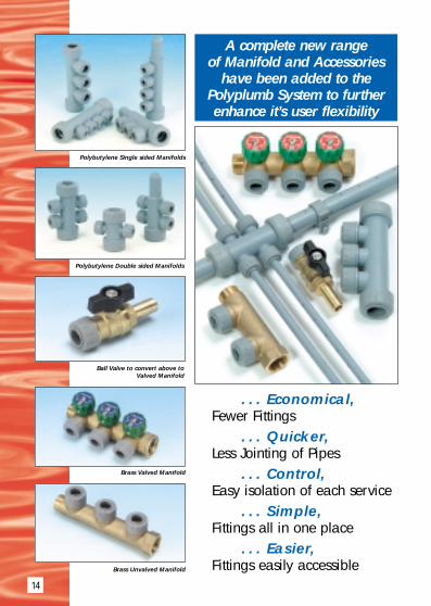
Polybutylene Single sided Manifolds
Polybutylene Double sided Manifolds
Brass Valved Manifold
Brass Unvalved Manifold
Ball Valve to convert above toValved Manifold
. . . Economical,Fewer Fittings
. . . Quicker, Less Jointing of Pipes
. . . Control,Easy isolation of each service
. . . Simple, Fittings all in one place
. . . Easier, Fittings easily accessible
A complete new range of Manifold and Accessories
have been added to thePolyplumb System to furtherenhance it’s user flexibility

15
Max length of pipe prior to 10mm connection
e.g. 10m = 5m flow and5m return 1 KW Rad 1·25 KW Rad 1·5 KW Rad
Max length of 10mm pipe total,e.g. 14m = 7m flow and 7m return
5 24 15 116 23 15 117 22 15 108 22 14 109 21 14 1010 20 13 1011 20 13 912 19 13 913 19 12 914 18 12 815 17 11 816 17 11 817 16 10 818 15 10 719 15 10 720 14 9 7
Polyplumb Manifold SystemFor use in most domestic and commercial hot and cold water supply andradiator heating projects, the Polyplumb Manifold System provides acentral connection point for water distribution.Available in resilient easy to use lightweightPolybutylene or traditional brass finish.Manifold plumbing which is ideally suited for usewith Polyplumb “pipe-in-pipe” technology, (wherescreed embedded pipework is used with minimaljoints) is employed in a similar way to simpleelectrical circuits, in that all services are suppliedfrom an easily accessible central distribution unit that
Polyplumb
Manifold
Typical BathroomLayout
using PolyplumbManifolds
Use of 10mm pipe for heating applicationsAs 10mm Polyplumb pipe is so flexible and can easily be positionedbehind dry lining, its use offers many installation advantages. As it is thesmallest of the pipe diameters offered in the Polyplumb range, restrictionson the use of 10mm pipe should be considered.Example: 10m of pipe prior to 10mm connection (5m flow, 5mreturn) used with 1.25 Kw Radiator.Maximum length of 10mm = 13m (6·5m flow, 6·5m return).

16
can be either wall mounted, placed in an unobstrusive void or housedwithin an inspection box and subsequent supply pipework cabled throughwall, floor or ceiling voids. Although Polyplumb Manifolds are available invarious port configurations they can be close coupled together to createmanifolds with any number of outlets.
Specific FeaturesThe lightweight Polybutylene manifolds are available both double socketedand socket/spigot ended with double sided or single sided Polyplumb pushfit ports, which readily accepts specially designed manifold ball valves.The brass manifold comes with 3/4” male and female BSP ends and areavailable both valved and unvalved.Valve head wheels incorporate twin disc identification indices, the lowerdisc displays the appliance or room supplied and the top disc displays thehot and cold blue and red symbols. A benefit of the valve manifold facilityis each pipe can be traced independently and isolated at one central point.The Polyplumb manifold range is ideal for “in-wall” applications such asspecial accommodation, Hotels and public houses where services arevirtually inaccessible or minimal joint use is demanded.
Application of Manifolds for Central Heating SystemsWhy use a Manifold?When employing normal acceptedplumbing technology for central heatingsystems, many fittings are used to divertthe water flow to the various radiatorsneeded to heat the home.For example, if you were supplying fourradiators with 10mm pipe from a 22mm flow and return supply, it wouldrequire 16 fittings (8 x 22mm x 15mmBranch Tees and 8 x 15mm x 10mmSocket Reducers) to complete the jobwhich would make 26 joints in all,conversely if you were to use the newPolyplumb 22mm x 10mm 4-portmanifolds you would only need to use 2fittings and create only 12 joints.Therefore using a manifold system is both economical, simpler and quicker by using less fittings and creating fewerjoints within cavities and voids.
22mm Supply Pipe
10mm Pipe to Radiator
4 x 22mm x 15mm Branch Tee
Radiator supply using Polyplumb 4-port manifold
22mm Supply Pipe
10mm Pipe to Radiator
1 x 4-port Manifold
4 x 15mm x 10mm Socket Reducer
Conventional radiator supply using multiple fittings
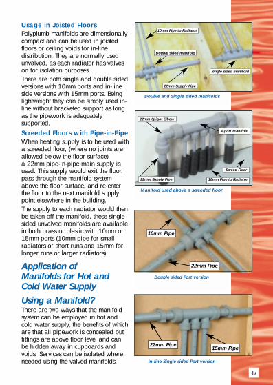
Usage in Joisted FloorsPolyplumb manifolds are dimensionallycompact and can be used in joistedfloors or ceiling voids for in-linedistribution. They are normally usedunvalved, as each radiator has valveson for isolation purposes.There are both single and double sidedversions with 10mm ports and in-lineside versions with 15mm ports. Beinglightweight they can be simply used in-line without bracketed support as longas the pipework is adequatelysupported.Screeded Floors with Pipe-in-PipeWhen heating supply is to be used witha screeded floor, (where no joints areallowed below the floor surface) a 22mm pipe-in-pipe main supply isused. This supply would exit the floor,pass through the manifold systemabove the floor surface, and re-enterthe floor to the next manifold supplypoint elsewhere in the building.The supply to each radiator would thenbe taken off the manifold, these singlesided unvalved manifolds are availablein both brass or plastic with 10mm or15mm ports (10mm pipe for smallradiators or short runs and 15mm forlonger runs or larger radiators).
Application of Manifolds for Hot and Cold Water SupplyUsing a Manifold?There are two ways that the manifoldsystem can be employed in hot andcold water supply, the benefits of whichare that all pipework is concealed butfittings are above floor level and canbe hidden away in cupboards andvoids. Services can be isolated whereneeded using the valved manifolds.
17
22mm Supply Pipe
10mm Pipe to Radiator
Double sided manifold
Single sided manifold
22mm Spigot Elbow
10mm Pipe to Radiator22mm Supply Pipe
4-port Manifold
Screed Floor
Manifold used above a screeded floor
Double sided Port version
In-line Single sided Port version
10mm Pipe
15mm Pipe
22mm Pipe
22mm Pipe
Double and Single sided manifolds

18
Localised Manifold SupplyLocalised supply is wherethe manifold is placedunobtrusively within a voidor cupboard or under thebath in the area supplied,i.e. bathroom, en-suite orkitchen area. The 22mmSupply pipe is fed throughthe house to the manifoldand then secondarysupply pipes are taken outof the ports to feed eachappliance, e.g. basin,bath or shower.
Centralised Manifold Supply
Centralised manifoldsupply is where themanifold distributes waterto each appliance directlyfrom a central cylindercupboard, where a seriesof valved manifold arededicated to each area,i.e. bathroom, en-suite, kitchen or utilityroom.
Using Manifold tocreate extra PortsOne clever design featureof the new PolyplumbManifold Range is thatboth polybutylene andbrass manifolds will jointogether to create extraPort facilities toaccommodate any numerof multiple service needs.
Localised supply design layout
Centralised supply design layout
Joining together of manifolds increases port outlets
Shower
BATHROOM
KITCHEN/UTILITY
EN-SUITE
BasinBath
Washing MachineDish Washer
Sink
Floor Level
Floor Level
22mm Supply Pipe
ShowerBasinBath
Valved Manifold
Valved Manifold
Hot Water
Cylinder
22mm Supply Pipe
EN-SUITE
KITCHEN/UTILITY
BATHROOM
Shower
Basin
Bath
Shower
Basin
Bath
Cylinder Cupboard
Washing MachineDish Washer
Sink
Valved Manifold
Valved Manifold
Hot Water
Cylinder
Floor Level

19
What Manifolds would you use?There are three distinct variations of manifold arrangement that can beemployed in the supply of hot and cold water. Both brass and plastic non-valved with separate push-fit ball valves or brass integrally valvedmanifolds can be used.The separate ball valve can also be used in-line where isolation is required away from the manifold (straight couplers are required toconnect to spigot end).
● 22mm PolybutyleneUnvalved Manifold
● 15mm Ports
● Single Sided
● Separate Spigot Ball Valves
● 3/4” Brass UnvalvedManifold
● 15mm Ports
● Single Sided
● Separate Spigot Ball Valves
● 3/4” Brass ValvedManifold
● 15mm Ports
● Single Sided
● Separate Spigot Ball Valves

20
Conduit pipe and Pipe-in-PipeThe conduit pipe coils (CPC15** and CPC22**)provide a conduit pipe which allows 15mm and22mm Polyplumb pipe to be laid in a floor screedwhilst conforming to Water Regulations. Theinstallation and application of the system is describedin the following section. The conduit pipe used inconjunction with the conduit boxes (JIB1 and JIB3)which house fittings, provides a cost effective andpractical pipework solution.
Pipe-in-Pipe SystemPolyplumb Pipe-in-Pipe consists of a polybutylenebarrier pipe encaseed within a black conduit pipe.The conduit provides protection for the polybutylenepipe in the installation process as well as allowingeasy withdrawal for future alteration or maintenance.
The installation procedure for conduit systemsis as follows:
1. Loosely position conduit boxes where required.2. Assemble fittings in boxes
Handy Tip: Where boxes abut a wall, i.e. elbows beneath radiators orsanitary appliances, boxes can be cut in two with the open end abuttingthe wall, this reduces the number of boxes required.
3. Drill conduit box using fitting assembly to determine hole position.4. Fix conduit box to floor.
Handy Tip: Use round drilled out sections of conduit box as washers. 5. Make joint at one end of pipe to be installed and cut pipe to length
required.6. Cut conduit to length required before threading conduit over pipe and
through hole in box to 2 or 3 corrugations.7. Push away pipe from end yet to be connected to allow grip onto the
pipe and push the pipe into the fitting before allowing conduit to coverpipe. Push conduit through hole in box to 2 or 3 corrugations.
Joints in screeded floors due to accidental damageWhere it is necessary to have joints in screeded floors, these joints must beaccessible. For example, where accidental damage to a pipe has occurred,it is recommened that the damaged section of pipe is removed and replacedusing Polyplumb straight couplers (PB0**). The section containing the jointsmust be installed within a Polyplumb Junction Inspection Box. PolyplumbJunction Inspection Boxes are manufactured to suit two screed depths;65mm (Product Code JIB3) - black in colour and 75mm (Product Code JIB1)- grey in colour. Both accept the 12mm plywood lid (Product Code JIB2) toprovide future access should it be required.

21
Pipe and Fitting BlankingPolyplumb pipes and fittings may need to be temporarily or permanentlyblanked for testing, avoidance of construction debris or future extensions.The pipe blanking cap (PB19**) fits on a pipe end and requires a pipestiffener whilst the fitting blanking cap (PB9**) blanks a fitting socket and isprovided complete with a pipe stiffener. Alternatively, pipes can be loopedtogether (e.g. radiator tails) using a section of pipe for temporary blankingduring testing.PaintingPolyplumb pipes and fittings can be painted using emulsion or undercoatand gloss. Cellulose based paints, strippers or thinners must not be used.Pipe InsulationPolyplumb has the same insulation requirements as copper. Where pipeinsulation is not required by Building or Water Regulations, but is preferredby the client for system efficiency, Polyplumb Pipe Insulation isrecommended. Where insulation is required by regulation, the PolyplumbPipe Insulation Plus should be used. The table below shows the insulationthickness and products required.
Pipe Water Bye-Law 49 Polyplumb PipeOD amended Jan 1990 Insulation Plus
(mm) (Cold Water) product required
Required Wall Thickness
15 25mm APP15251/2
22 19mm APP22191/2
28 19mm APP28191/2
Product Linesneeded to meet
Service orRegulation
requirements
Pipe Building Regulations Polyplumb Pipe Building Regulations Polyplumb PipeOD L1-Section 3 1995 Insulation Plus L1-Section 3 1995 Insulation Plus
(mm) (Hot Water) product required (Domestic Heating) product required
Required Required Wall Thickness Wall Thickness
15 13mm APP15191/2 15mm APP15191/2
22 13mm APP22191/2 22mm APP22251/2
28 13mm APP28191/2 – –
Note: Polyplumb Pipe Insulation Plus has a thermal conductivity of 0·038W/mK at 40°C.
22
Electrical safetyWhere Polyplumb pipe breaks the continuity of existing metal pipe, whichmay be used for earthing, or bonding this continuity should be re-instatedby affixing permanent earth clips and a section of earth cable between thecopper ends on either side of the Polyplumb sections.Equipotential bondingBoth the IEE and The Institute of Plumbing now give guidance on the Earth Bonding requirements of Plastic Pipe systems. As Polyplumb pipe doesnot conduct electricity, installations generally require less equipotentialbonding than metal systems although if in doubt exact guidance should besought.System TestingPressure testing of systems is recommended.1st fix Installations Pipe and fittings only should be tested. The system shouldbe completely filled using water at not more than 20°C at a test pressure of18 Bar which should be applied for not less than 15 minutes and no longerthan 1 hour. Joint security can be checked visually and by tugging at joints.2nd fix Installations (complete installations including appliances) should betested with water to the maximum test pressure allowed by manufacturers ofthe appliances and fittings.Pressure Testing in sub zero temperaturesSpecial precautions are necessary if the pressure testing is to take place insub-zero temperatures.This applies particularly in under floor central heating systems using thescreeded floor system where most of the pipe is encased in concrete. Due tothe contact between pipe and floor panel on screeded installations, wherethe screed does not completely surround the pipe, there may be pointswhere strain is created on the pipe in freezing conditions which is notnormally present. Therefore it is advisable to drain the under floor centralheating system once testing and screeding has been completed. Precautionsshould also be taken where installations contain large quantities of fittingswhich due to the rigidity of their construction may put undue pressure on thepipe.System ChlorinationShort term chlorination for disinfection of supply pipework and normallevels of chlorine in UK domestic water supplies will not have an adverseeffect on Polyplumb. Polyplumb is not suitable however for systems thatcarry a high concentration of chlorine, i.e. supplies to swimming pools etc.
Handling and Storage of Polyplumb productsThe Packaging of both pipes and fitting is designed to protect fromultraviolet light and environmental contamination. Pipes and fittings shouldtherefore be retained in their packaging as long as possible, and should bestored in a cool dry area. When on site, fittings should be stored to prevent dust and debris fromentering the fitting and sticking to the pre-lubricated “O” ring. Care shouldbe taken to avoid scratching the pipe surface during installation.

23 PRODUCT RANGE

Stainless steel pipe stiffeners must be used whenever Polybutylene pipe is jointed into a Polyplumb socketed fitting or a compression fitting.24
PRODUCT DESCRIPTION CODE NO.
Standard Pipe Cut Length15mm x 3 metre Cut Length PB31515mm x 6 metre Cut Length PB61522mm x 3 metre Cut Length PB32222mm x 6 metre Cut Length PB62228mm x 3 metre Cut Length PB32828mm x 6 metre Cut Length PB628
Barrier Pipe Cut Length15mm x 3 metre Cut Length PB315B15mm x 6 metre Cut Length PB615B22mm x 3 metre Cut Length PB322B22mm x 6 metre Cut Length PB622B28mm x 3 metre Cut Length PB328B28mm x 6 metre Cut Length PB628B
Standard Pipe Coils10mm x 50 metre Coil PB501010mm x 100 metre Coil PB1001015mm x 25 metre Coil PB251515mm x 50 metre Coil PB501515mm x 100 metre Coil PB1001522mm x 25 metre Coil PB252222mm x 50 metre Coil PB5022
Barrier Pipe Coils10mm x 50 metre Coil PB5010B10mm x 100 metre Coil PB10010B15mm x 25 metre Coil PB2515B15mm x 50 metre Coil PB5015B15mm x 100 metre Coil PB10015B15mm x 150 metre Coil PB15015B22mm x 25 metre Coil PB2522B22mm x 50 metre Coil PB5022B28mm x 25 metre Coil PB2528B28mm x 50 metre Coil PB5028B
Polyplumb Polybutylene Pipe-10,15,22&28mm O.D.
End Section
End Section
Featuring “Plumb Straight”Coiling Technology
Featuring “Plumb Straight”Coiling Technology
25
PRODUCT DESCRIPTION CODE NO.
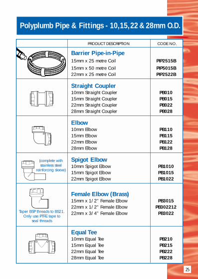
Barrier Pipe-in-Pipe15mm x 25 metre Coil PIP2515B15mm x 50 metre Coil PIP5015B22mm x 25 metre Coil PIP2522B
Straight Coupler10mm Straight Coupler PB01015mm Straight Coupler PB01522mm Straight Coupler PB02228mm Straight Coupler PB028
Elbow10mm Elbow PB11015mm Elbow PB11522mm Elbow PB12228mm Elbow PB128
Spigot Elbow10mm Spigot Elbow PB101015mm Spigot Elbow PB101522mm Spigot Elbow PB1022
Female Elbow (Brass)15mm x 1/2” Female Elbow PB301522mm x 1/2” Female Elbow PB30221222mm x 3/4” Female Elbow PB3022
Equal Tee10mm Equal Tee PB21015mm Equal Tee PB21522mm Equal Tee PB22228mm Equal Tee PB228
Polyplumb Pipe & Fittings - 10,15,22 &28mm O.D.
(complete with stainless steel
reinforcing sleeve)
Taper BSP threads to BS21.Only use PTFE tape to
seal threads

26
PRODUCT DESCRIPTION CODE NO.
End Reduced Tee15mm x 10mm x 15mm End Red. Tee PB141522mm x 15mm x 22mm End Red. Tee PB142228mm x 22mm x 28mm End Red. Tee PB1428
Branch Reduced Tee15 x 15 x 10mm Branch Reduced Tee PB111522 x 22 x 10mm Branch Reduced Tee PB11221022 x 22 x 15mm Branch Reduced Tee PB112228 x 28 x 22mm Branch Reduced Tee PB1128
Branch Reduced Spigot Tee(complete with stainless steel reinforcing sleeve)15 x 15 x 10mm Branch Red. Spigot Tee PB121522 x 22 x 15mm Branch Red. Spigot Tee PB1222
Branch & One End Reduced Tee15 x 10 x 10mm Branch End Red. Tee PB151522 x 15 x 15mm Branch End Red. Tee PB152228 x 22 x 22mm Branch End Red. Tee PB1528
Two Ends Reduced Tee15 x 15 x 22mm 2 Ends Red. Tee PB1622
Female Tee (Brass)15mm x 1/2” Female Tee PB291522mm x 1/2” Female Tee PB292212
Reducing Coupling22mm x 10mm Socket Reducer PB582210
Spigot Reducer15mm x 10mm Spigot Reducer PB81522mm x 15mm Spigot Reducer PB82228mm x 22mm Spigot Reducer PB828
Polyplumb Fittings - 10,15,22 &28mm O.D.
Taper BSP threads to BS21.Only use PTFE tape to
seal threads
(complete with stainless steelreinforcing sleeves)
27
PRODUCT DESCRIPTION CODE NO.
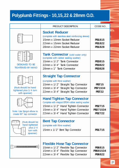
Socket Reducer(complete with stainless steel reinforcing sleeve)15mm x 10mm Socket Reducer PB181522mm x 15mm Socket Reducer PB182228mm x 22mm Socket Reducer PB1828
Tank Connector (cold water only)(complete with rubber sealing washer)15mm x 1/2” Tank Connector PB381522mm x 3/4” Tank Connector PB382228mm x 1” Tank Connector PB3828
Straight Tap Connector(complete with fibre washer)15mm x 1/2” Straight Tap Connector PB71515mm x 3/4” Straight Tap Connector PB7153422mm x 3/4” Straight Tap Connector PB722
Hand Tighten Tap ConnectorComplete with integral EPDM rubber sealing washer
15mm x 1/2” Hand Tighten Connector PB271515mm x 3/4” Hand Tighten Connector PB27153422mm x 3/4” Hand Tighten Connector PB2722
Bent Tap Connector(complete with fibre washer)
15mm x 1/2” Bent Tap Connector PB1715
Flexible Hose Tap Connector15mm x 1/2” Flexible Tap Connector PB681515mm x 3/4” Flexible Tap Connector PB68153422mm x 3/4” Flexible Tap Connector PB6822
Polyplumb Fittings - 10,15,22 &28mm O.D.
(Nuts should be handtightened plus 1/4 turn
with spanner)
Note: Use Spigot elbow tocreate 90° tap connector
(Nuts should behand tightened
plus 1/4turn withspanner)
DESIGNED TO BETIGHTENED BY HAND

28
PRODUCT DESCRIPTION CODE NO.
Reducing Bush(complete with fibre washer)1/2” x 3/8” Reducing Bush PB3415
Male BSP Socket Adaptor10mm x 1/4” MBSP Adaptor PB431010mm x 3/8” MBSP Adaptor PB43103815mm x 1/2” MBSP Adaptor PB431522mm x 3/4” MBSP Adaptor PB432228mm x 1” MBSP Adaptor PB4328
Male BSP Spigot Adaptor10mm x 1/4” MBSP Spigot Adaptor PB541015mm x 1/2” MBSP Spigot Adaptor PB541522mm x 3/4” MBSP Spigot Adaptor PB542228mm x 1” MBSP Spigot Adaptor PB5428
Female BSP Adaptor10mm x 1/4” Female BSP Adaptor PB441010mm x 3/8” Female BSP Adaptor PB44103815mm x 1/2” Female BSP Adaptor PB441515mm x 3/4” Female BSP Adaptor PB44153422mm x 3/4” Female BSP Adaptor PB442228mm x 1” Female BSP Adaptor PB4428
Female BSP Spigot Adaptor10mm x 1/4” FBSP Spigot Adaptor PB551015mm x 1/2” FBSP Spigot Adaptor PB551522mm x 3/4” FBSP Spigot Adaptor PB552228mm x 1” FBSP Spigot Adaptor PB5528
Polyplumb Fittings - 10,15,22 &28mm O.D.
(DZR Brass Body)Parallel BSP threads to
BS21. Only use PTFE tapeto seal threads.
(DZR Brass Body)Parallel BSP threads to
BS21. Only use PTFE tapeto seal threads.
(DZR Brass Body)Taper BSP threads to BS21.
Only use PTFE tape to seal threads.
(DZR Brass Body)Taper BSP threads to BS21.
Only use PTFE tape to seal threads.
(DZR Brass Body)Taper BSP threads to BS21.
Only use PTFE tape to seal threads.

29
PRODUCT DESCRIPTION CODE NO.
Compression Adaptors15mm x 15mm Compression Adaptor PB711522mm x 22mm Compression Adaptor PB7122
MDPE Polyfast Adaptor(Cold Water only)All include MDPE 12 Bar Plastic Pipe Stiffener15mm x 20mm MDPE Adaptor PB42201515mm x 25mm MDPE Adaptor PB42251522mm x 25mm MDPE Adaptor PB42252222mm x 32mm MDPE Adaptor PB42322228mm x 32mm MDPE Adaptor PB423228
MDPE Push-Fit Adaptor(Cold Water only)All include MDPE 12 Bar Plastic Pipe Stiffener15mm x 20mm MDPE Adaptor PB45201515mm x 25mm MDPE Adaptor PB45251522mm x 25mm MDPE Adaptor PB45252222mm x 32mm MDPE Adaptor PB45322228mm x 32mm MDPE Adaptor PB453228
Spigot Draincock (Brass)15mm Spigot Draincock PB3615
Wall Plate Elbow (Brass)15mm x 1/2” BSP Wall Plate Elbow PB131522mm x 1/2” BSP Wall Plate Elbow PB13221228mm x 1/2” BSP Wall Plate Elbow PB132812
Wall Plate Elbow (Plastic)15mm x 1/2” BSP Wall Plate Elbow PB531522mm x 1/2” BSP Wall Plate Elbow PB53221222mm x 3/4” BSP Wall Plate Elbow PB5322
Polyplumb Fittings - 10,15,22 &28mm O.D.
Parallel BSP threadsto BS21. Only use
PTFE tapeto seal threads.
Parallel BSP threadsto BS21. Only use
PTFE tapeto seal threads.

30
PRODUCT DESCRIPTION CODE NO.
Polyplumb Fittings - 10,15,22 &28mm O.D.
Wall Plate Tee (Brass)15mm x 1/2” BSP Wall Plate Tee PB511522mm x 1/2” BSP Wall Plate Tee PB512212
Cylinder Connector (Brass)22mm Cylinder Connector PB41221” BSP thread to BS2779
Metric Polyb.Welding Adaptor28 x 32mm Metric Welding Adaptor PB6928(can be electrofusion or butt welded)
Spigot Blank End10mm Spigot Blank End PB91015mm Spigot Blank End PB91522mm Spigot Blank End PB92228mm Spigot Blank End PB928
Socket Blank End10mm Socket Blank End PB191015mm Socket Blank End PB191522mm Socket Blank End PB192228mm Socket Blank End PB1928
Pipe Stiffener (Stainless Steel)10mm Pipe Support Sleeve PB641015mm Pipe Support Sleeve PB641522mm Pipe Support Sleeve PB642228mm Pipe Support Sleeve PB6428
(complete with stainless steelreinforcing sleeve)
(must be used withPolybutylene pipe)
Parallel BSPthreads to BS21.
Only use PTFE tapeto seal threads.

31
PRODUCT DESCRIPTION CODE NO.
Gate Valve (Brass)15mm Gate Valve PB311522mm Gate Valve PB3122
Thermostatic Radiator Valve(Plated Brass)10mm Thermostatic Radiator Valve PB331015mm Thermostatic Radiator Valve PB3315(Note: only use P.T.F.E. tape to seal threads)
Radiator/Lockshield Valve (Plated Brass)10mm Radiator Valve PB321015mm Radiator Valve PB3215(Note: only use P.T.F.E. tape to seal threads)
Radiator Draincock (Plated Brass)Radiator Draincock PB3515(Note: only use P.T.F.E. tape to seal threads)
Straight Service Valve(not for central heating)
15mm x 1/2” Straight Service Valve PB6515
Polyplumb Fittings - 10,15,22 &28mm O.D.
40mm40mm
40mm40mm

32
PRODUCT DESCRIPTION CODE NO.
Polyplumb Fittings - 10,15,22 &28mm O.D.
90º Bent Service Valve(not for central heating)
15mm x 1/2” 900 Bent Service Valve PB661515mm x 15mm 900 Bent Service Valve PB7915
Shut-Off Valve(not for central heating)
15mm x 15mm Shut-Off Valve- Warm PB591515mm x 15mm Shut-Off Valve - Cold PB6015
Appliance Valve(not for central heating)
15mm x 3/4” Appliance Valve- Warm PB611515mm x 3/4” Appliance Valve - Cold PB6215
Double Check Valve(cold water only)
15mm Double Check Valve PB371522mm Double Check Valve PB372228mm Double Check Valve PB3728
Stopcock(cold water only)15mm x 15mm Stopcock PB261522mm x 22mm Stopcock PB2622
Stopcock MDPE Polyfast(cold water only)
20mmx15mm Stopcock MDPE Polyfast PB26201525mmx15mm Stopcock MDPE Polyfast PB26251525mmx22mm Stopcock MDPE Polyfast PB262522
White
White
With MDPE Polyfast Compression Inlet Sockets/Pipe Stiffener see Polyfast Adaptor section
for adaption to other pipe materials.

33
Polyplumb Fittings - 10,15,22 &28mm O.D.
PRODUCT DESCRIPTION CODE NO.
Stopcock MDPE Push-fit(cold water only)
20mm x 15mm Stopcock MDPE Push-fit PB29201525mm x 15mm Stopcock MDPE Push-fit PB29252125mm x 22mm Stopcock MDPE Push-fit PB292522
Radiator Connector Bend(RCB)10mm Radiator Connector Bend PB391015mm Radiator Connector Bend PB3915(Pipe stiffeners must be used on each end)
Quarter Turn Ball Valve(Nickel Plated Brass)15mm Quarter Turn Ball Valve PB6715
Quarter Turn Ball Valve(Nickel Plated Brass)22mm Quarter Turn Ball Valve PB6722
Quarter Turn Ball Valve(Nickel Plated Brass)28mm Quarter Turn Ball Valve PB6728
100mm
150m
m Patent Pending
With MDPE Push-fit Push-fit Inlet Sockets/Pipe Stiffener see Push-fit Adaptor section
for adaption to other pipe materials.

34
Polyplumb Manifold System
PRODUCT DESCRIPTION CODE NO.
Manifold (Polybutylene)22mm x10mm - 2 Port (Socket/Socket) PB2822
Manifold (Polybutylene)22mm x10mm - 4 Port (Socket/Socket) PB4822
Manifold (Polybutylene)22mm x10mm - 4 Port (Blanked Spigot/Socket) PB4922
Manifold (Polybutylene)22mm x15mm - 3 Port (Socket/Socket) PB7322153
Manifold (Polybutylene)22mm x15mm - 3 Port (Blanked Spigot/Socket) PB7622153
Manifold (Polybutylene)22mm x10mm - 4 Port (Socket/Socket) PB7322104
Manifold (Polybutylene Body)22mm x10mm - 4 Port (Blanked Spigot/Socket) PB4922
Cut Blank End and fit pipe stiffener to continue runPB582210 can be fitted to spigot to provide
a fourth 10mm socket connection.
Cut Blank End and fit pipe stiffener to continue runPB582210 can be fitted to spigot to provide
a fifth 10mm socket connection.
Cut Blank End and fit pipe stiffener to continue runPB582210 can be fitted to spigot to provide
a fifth 10mm socket connection.

35
PRODUCT DESCRIPTION CODE NO.
Brass Single Sided Manifold Unvalved15mm x 3/4” Female/Male BSP 2 Port PB47152
Brass Single Sided Manifold Unvalved15mm x 3/4” Female/Male BSP 3 Port PB47153
Brass Single Sided Manifold Valved15mm x 3/4” Female/Male BSP 2 Port PB234152
Brass Single Sided Manifold Valved15mm x 3/4” Female/Male BSP 3 Port PB234153
Ball Valve15mm 15mm Ball Valve (Socket/Spigot) PB4015
Manifold Bracket (Metal)3/4” Manifold Bracket PB4634
Barrier Pipe-in-Pipe15mm x 25 metre Coil PIP2515B15mm x 50 metre Coil PIP5015B22mm x 25 metre Coil PIP2522B
Polyplumb Manifold System
Must be used on installations where a British Gas 3 Star Service contract is to be in place

36
PRODUCT DESCRIPTION CODE NO.
Polyplumb Ancillaries
Bulldog Clips (Polypropylene)15mm Bulldog Clip PB211522mm Bulldog Clip PB212228mm Bulldog Clip PB2128
Nail-In Clips (Polypropylene)10mm Nail-In Clip PB221015mm Nail-In Clip PB221522mm Nail-In Clip PB222228mm Nail-In Clip PB2228
Snap-Fit Clips (Polypropylene)10mm Snap-Fit Clip PB231015mm Snap-Fit Clip PB231522mm Snap-Fit Clip PB232228mm Snap-Fit Clip PB2328
Pipe Clip Spacer (Polypropylene)10mm Pipe Clip Spacer PB241015mm Pipe Clip Spacer PB241522mm Pipe Clip Spacer PB242228mm Pipe Clip Spacer PB2428
Bend Former15mm Bend Former PB631522mm Bend Former PB6322
‘O’-Rings (EPDM Rubber)3/4” Imperial ‘O’-Ring PB9034(Note: Must be lubricated before use)
For use with
Snap-FitClips
Note: Clips can beconnected togetherto aid alignment
(Bend radius 8 x pipe diameter)

37
PRODUCT DESCRIPTION CODE NO.
Polyplumb Ancillaries
Spares Component Kit10mm Spares Component Kit PB951015mm Spares Component Kit PB951522mm Spares Component Kit PB952228mm Spares Component Kit PB9528
Irish Copper Adaptor Set3/4” Irish Copper Adaptor Set PB70341” Irish Copper Adaptor Set PB701
Conical EPDM Sealing Washer(For tap connector with brass nut)1/2” Sealing Washer PB93123/4” Sealing Washer PB9334
Flat EPDM Sealing Washer(For hand tighten tap connector)1/2” Sealing Washer PB94123/4” Sealing Washer PB9434
Conduit Pipe Coils (Polypropylene)15mm x 25 metre Conduit Pipe Coil CPC152515mm x 50 metre Conduit Pipe Coil CPC155022mm x 25 metre Conduit Pipe Coil CPC222522mm x 50 metre Conduit Pipe Coil CPC2250
Boiler Overflow Pipe Guard(Comes with x2 Pipe Clips)Boiler Overflow Pipe Guard BOPG50
Junction Inspection Box(Polypropylene)Junction Box L 400 x W 210 x H 75mm JIB1Junction Box Lid (12mm Plywood) JIB2Junction Box L400 x W210 x H65mm JIB3
WidthLength
Height

38
PRODUCT DESCRIPTION CODE NO.
Polyplumb Ancillaries
System Test KitPolyplumb System Test Kit PB993
Valve Tidy Cover (Polypropylene)Radiator Valve Cover VT149(Six Valve Tidy’s per pack)Complete with Pipe Adaptors for10mm/8mm pipe
Pipe CuttersStandard Pipe Cutter 10mm to 28mm PB777Standard type Replacement Blades PB780
Pipe CuttersRatchet type cutters 10mm to 28mm PB778Ratchet type Replacement Blades PB779
Silicone Lubricant100gm Screw Top Jar SG100
Solvent Cement ❉c/w Brush 125ml (BS6209) SC125
Solvent Cement ❉c/w Brush 250ml (BS6209) SC250
Solvent Cement ❉c/w Brush 500ml (BS6209) SC500
Cleaning Fluid ❉250ml Tin CF250
❉ Only for use with PVCu floorduct components.
39
PRODUCT DESCRIPTION CODE NO.
Polyplumb Ancillaries
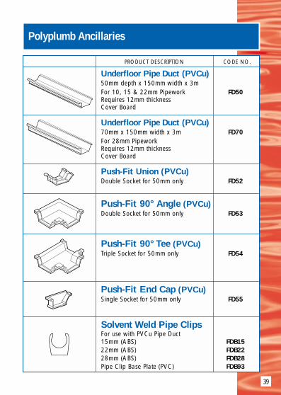
Underfloor Pipe Duct (PVCu)50mm depth x 150mm width x 3mFor 10, 15 & 22mm Pipework FD50Requires 12mm thicknessCover Board
Underfloor Pipe Duct (PVCu)70mm x 150mm width x 3m FD70For 28mm PipeworkRequires 12mm thickness Cover Board
Push-Fit Union (PVCu)Double Socket for 50mm only FD52
Push-Fit 90° Angle (PVCu)Double Socket for 50mm only FD53
Push-Fit 90° Tee (PVCu)Triple Socket for 50mm only FD54
Push-Fit End Cap (PVCu)Single Socket for 50mm only FD55
Solvent Weld Pipe ClipsFor use with PVCu Pipe Duct15mm (ABS) FDB1522mm (ABS) FDB2228mm (ABS) FDB28Pipe Clip Base Plate (PVC) FDB93

40
PRODUCT DESCRIPTION CODE NO.
15mm Polyplumb Insulation15mm x 9mm x 1 metre APL1509115mm x 9mm x 2 metre APL1509215mm x 13mm x 1 metre APL1513115mm x 13mm x 2 metre APL15132
22mm Polyplumb Insulation22mm x 9mm x 1 metre APL2209122mm x 9mm x 2 metre APL2209222mm x 13mm x 1 metre APL2213122mm x 13mm x 2 metre APL22132
28mm Polyplumb Insulation28mm x 9mm x 1 metre APL2809128mm x 9mm x 2 metre APL2809228mm x 13mm x 1 metre APL2813128mm x 13mm x 2 metre APL28132
Polyplumb Pipe Insulation Flame retardent cellular polyethylene
(Bore x Wall x Length)
(Bore x Wall x Length)
(Bore x Wall x Length)
Product Linesneeded to meet
Service orRegulation
requirements
Pipe Water Bye-Law 49 Polyplumb PipeOD amended Jan 1990 Insulation Plus
(mm) (Cold Water) product requiredRequired
Wall Thickness
15 25mm APP15251/2
22 19mm APP22191/2
28 19mm APP28191/2

41
PRODUCT DESCRIPTION CODE NO.
Polyplumb Pipe Insulation
15mm Polyplumb Insulation Plus15mm x 19mm x 1 metre APP1519115mm x 19mm x 2 metre APP1519215mm x 22mm x 2 metre APP1522215mm x 25mm x 2 metre APP15252
22mm Polyplumb Insulation Plus22mm x 19mm x 1 metre APP2219122mm x 19mm x 2 metre APP2219222mm x 25mm x 1 metre APP2225122mm x 25mm x 2 metre APP22252
28mm Polyplumb Insulation Plus28mm x 19mm x 1 metre APP2819128mm x 19mm x 2 metre APP28192
Flame retardent cellular polyethylene
(Bore x Wall x Length)
(Bore x Wall x Length)
(Bore x Wall x Length)
Building Regulations Polyplumb Pipe Building Regulations Polyplumb PipeL1-Section 3 1995 Insulation Plus L1-Section 3 1995 Insulation Plus
(Hot Water) product required (Domestic Heating) product requiredRequired Required
Wall Thickness Wall Thickness
13mm APP15191/2 15mm APP15191/2
13mm APP22191/2 22mm APP22251/2
13mm APP28191/2 – –

42
the Polyplumb system ... it’s about time!
NEW UNDERFLOOR CENTRALHEATING SYSTEMS
quicker- jointingwith Polyplumb Fittings
easier- pipework routingwith PLUMB STRAIGHT Technology
more choice - three easy to apply systems to choose from
Solid Floor
Suspended Floor
Floating Floor

Polyplumb SystemPolyplumb barrier pipe can be used in underfloor central heating systems,which can be used with, or instead of, steel panel radiators. Underfloorcentral heating (UFCH) gives “invisible” warmth - ideal for modern living,giving clean interior design and maximum usable wall space. UFCH issafer and cleaner than radiator systems as there are no hot surfaces, anddust and air movement are minimised. UFCH also has the benefit of lowmaintenance with no requirement to paint radiators.
Where radiator central heating systems workprimarily by creating convection currents ofhot air supplemented by some radiated heat,underfloor central heating systems workprimarily by heat radiation supplemented bysome convection. As the floor radiates heatuniformly over its surface there is uniform heatdistribution - no hot and cold spots - consistentcomfort. And best of all, a warm floor - eventhe best radiator systems can leave you withcold feet.
Polyplumb offers three configurations ofunderfloor central heating suitable for newbuild, retrofit, or any type of construction. Allare compatible with standard central heatingboilers and are especially suitable for use withcondensing boilers which give maximumefficiency at low output levels.
The Polyplumb UFCH systems involves nospecialist equipment or “science”. Rather it involves simple application ofstandard Polyplumb piping fittings plus one specialist manifold.
Advisory ServiceIt is simple to select the appropriate Polyplumb UFCH system, to ensure thesystem is suitable for a particular building, to size the boiler, and toestimate and purchase. The Polyplumb Advisory Service is available toassist where necessary in products and detailing. Installer training coursesare available. Enquirers may request details from our database of trainedinstallers.
43
Polyplumb Underfloor Central Heating Systems

44
Polyplumb Underfloor Central Heating Systems
screed minimum 70mm fromPolyplumb screeded floor panelbase, or 50mm from pipe top.Screed additive may be used.Consult Polypipe for details.
solid / structural sub-base
Polyplumb pipe in Polyplumbscreeded floor panel at 100mm or200mm centres as required
insulation board on damp proofmembrane as required byBuilding Regulations
edge insulation / isolation joint
Solid Floor - System
The maximum heat performancefrom a solid floor with a roomtemperature of 21°C and a floortemperature of 29.9°C is99W/m2. The maximum pipelength is 100m. At 100mm pipecentres pipe requirement =8.2m/m2 and maximum floorcoverage per circuit = 11.1m2.At 200mm pipe centres piperequirement = 4.5m/m2 andmaximum floor coverage percircuit = 21.2m2.
Polyplumb underfloor central heating in solid or screeded floorsincorporates the unique Polyplumb screeded floor panel. The light weightplastic floor panels “nest” for space saving storage and are easily carried.Once in the room they are easily cut to the room shape. They form asimple grid for the quickest possible pipe laying and form a precise guidefor minimum bending radius. They set the pipe at exact centres and holdthe pipe against movement when screeding. The floor panel holds the pipeabove the insulation allowing full screed surround. Optimum screed depthis 70mm from panel base or 40mm from the pipe top.
Insulation below and at the edges of the floor sceed is as required byBuilding Regulations or greater if desired by personal preference. Edgeinsulation also acts as an expansion joint.
at 45°C at 50°C at 55°Cflow temp flow temp flow temp
18°C 100 75 92 109
200 62 75 89
21°C 100 65 82 99
200 53 67 90
22°C 100 62 79 95
200 51 64 78
Target Room Temp.
W/m2Pipe
Centres(mm)

45
Polyplumb Underfloor Central Heating Systems
Solid Floor - System DesignSystem design is a simple five step process which matches what the UFCHsystem can deliver to the room requirements in W/m2..
Step one : Calculate the heat loss for each room by an elemental method, ie separatecalculations for wall loss, window loss,ventilation loss etc. Floor loss can be ignored atthis stage. Divide total loss by floor area to findheat requirement in W/m2 . See table on page40 for heat outputs of UFCH.
Step two : If a heat input of less than 100W/m2 isrequired, a Polyplumb UFCH solid floor systemcan be used without the need for additionalradiators.If a heat output of more than 100W/m2 isrequired, a Polyplumb UFCH solid floor systemmay be used with additional radiators as required.
Step three : Select the required boiler flow temperature from the table on page 40.Obviously this must be common for all rooms. Select the worst case roomfirst.
Step four :Determine the pipe spacing from the table on page 40. This is based on astandard 40mm screed above the pipe and an allowance of 0.1 W/mKfor floor covering.
Step five :Design piping circuits with maximum pipe circuit length of 100m. If theroom is so large that one circuit of 100m is not adequate then two smallercircuits should be designed. The best circuit design is a spiral. Note : 8.2m/m2 pipe required at 100mm spacing. 4.5m/m2 piperequired at 200mm spacing

1. Lay the floor insulation in accordance with BuildingRegulations. Lay self adhesive edge insulation withpolystyrene closest to wall
2. Lay the interlocking Screeded Floor Panels. Stickdown at edges with adhesive strip on edge insulation
3. Install Polyplumb pipe in a spiral configuration.
See System Design section for pipe spacing.
Maximum pipe circuit length = 100m.
4. No single area of screed should exceed 40m2.Areas greater than this should be separated by edgingstrip to form an expansion joint. Where the Polyplumbpipe passes through the insulation strip, ie where pipesenter and leave the room, the pipe should be shieldedwith protective sleeves for 40cm each side of the strip.Protective sleeves should also be used around the pipeas it exits the screed near the manifold
5. Connect the flow and return ends at each end ofthe manifold using pipe stiffeners on the pipe end.
Note Push fit joints for 15mm pipes and compressionjoints for 18mm pipes.
6. Complete the distribution box installation and usevalve actuators if required
7. Pressure test the system at 6 bar before flooringscreed is poured. Maintain a constant pressure of3 bar throughout floor screeding and curing. Refer topage 18 for special precautions.
8. Screed to optimum depth of 40mm from pipe top(70mm from panel base).Allow the screed to drynaturally. The heatingsystem should not be usedto force dry the screed.When the underfloorheating is switched on itshould be allowed towarm up gently over aperiod of days
Solid Floor Installation Instructions
46

9
tongue and groove flooring
ceiling
Polyplumb pipe - may beclipped to sides of joists
mineral wool insulation filling voidsbetween joists or foam insulation onbattens fixed to sides of joists
Polyplumb Underfloor Central Heating Systems
Suspended Floor - SystemPolyplumb underfloor central heating in suspended floors is achieved bylaying pipe between the floor joists above mineral wool or foam boardinsulation. This can be done from above or below. When working frombelow the Polyplumb pipe is simply clipped in place at the tops of thesides of the joists. Alternatively the Polyplumb pipe may be run betweencounter battens above the joists. As anoption the Polyplumb pipe may be laid intometal Polyplumb heat spreader plates. These plates may be considered to offeradvantages in uniform spread of heat andspeed of heating from cold.
at 50°C at 55°C at 60°Cflow temp flow temp flow temp
18°C 300 53 63 72
21°C 300 47 57 66
22°C 300 45 55 65
The maximum heat performancefrom a suspended floor with aroom temperature of 21°C anda floor temperature of 27.2°C is66W/m2. The maximum pipelength is 80m. At 225mm pipecentres pipe requirement =4m/m2 and maximum floorcoverage per circuit = 20m2.At 300mm pipe centres piperequirement = 3.1m/m2 andmaximum floor coverage percircuit = 25.8m2.
Target Room Temp.
W/m2
Pipe Centres(mm)
47

48
Polyplumb Underfloor Central Heating Systems
Suspended Floor - System DesignSystem design is a simple five step process which matches what the UFCHsystem can deliver to the room requirements in W/m2..
Step one : Calculate the heat loss for each room by an elemental method, ie separatecalculations for wall loss, window loss, ventilation loss etc. Floor loss canbe ignored at this stage. Divide total loss by floor area to find heat
requirement in W/m2 . See table on page 43for heat outputs of underfloor heating.
Step two : If a heat input of less than 70W/m2 isrequired, a Polyplumb UFCH suspended floorsystem can be used without the need foradditional radiators.If a heat output of more than 70W/m2 isrequired a Polyplumb UFCH suspended floorsystem may be used with additional radiatorsas required.
Step three : Select the required boiler flow temperature from the table on page 43.Obviously this must be common for all rooms. Select the worst case room first.
Step four :Pipe spacing is assumed to be at a maximum of 300mm, ie two pipesbetween joists at 600mm centres. This is based on a standard 18mm chipboard above the pipe and an allowance of 0.1 W/mK for floor covering.
Step five :Design piping circuits with maximum pipe circuit length of 80m. If theroom is so large that one circuit of 80m is not adequate then two smallercircuits should be designed. The best circuit design is a zig zag.

49
All installations must comply with Building Regulationsand local authority requirements.Suspended Floor Option A1. Fill all the voids between joists with appropriatemineral wool or foam insulation 2. Lay the Polyplumb pipe on top of the insulation.Generally allow the pipe to run and return betweeneach pair of joists giving piping at 225mm to 300mmcentres. Notch out the top of the joists where it isnecessary to cross them. Maximum pipe circuit length = 80m. Then go to step 6Note : This method can also be used in reverse ifinstalling from below. Go to note 5Suspended Floor Option B (Joists at 450mm centres)1. Fill all the voids between joists with appropriatemineral wool or foam insulation. 2. Lay Polyplumb double heat spreader plates betweenthe joists and pin in position. Leave 300mm gap atreturn end for bending pipe to return and trim battensto penultimate joist at opposite ends3. Lay pipe in heat spreader plates4. For joist centres other than 450mm counter battenat either 300mm or 450mm and use single or doubleheat spreader plates as described.Options A and B5. Connect the flow and return ends at each end of themanifold using pipe stiffeners on the pipe end. Note these are push fit joints 6. Complete thedistribution boxinstallation and usevalve actuators ifrequired7. Pressure test thesystem at 6 bar beforeconcealing the pipe.Refer to page 18 forspecial precautions.
Suspended Floor Installation Instructions

50
Polyplumb Underfloor Central Heating Systems
Floating Floor - SystemPolyplumb underfloor central heating isideal for floating floors above existingtimber or solid sub-base. It incorporatesthe Polyplumb floating floor panelwhich is a foam insulation sheet withpre-formed pipe slots at 300mmcentres. Each panel includes pipebending grooves.
tongue and groove flooring
concrete or timber sub-floor
Polyplumb pipe in heat spreader plate
pre-formed Polyplumb floating floorinsulation panel
damp proof membrane asrequired by BuildingRegulations
at 50°C at 55°C at 60°Cflow temp flow temp flow temp
18°C 300 53 63 72
21°C 300 47 57 66
22°C 300 45 55 65
The maximum heat performancefrom a floating floor with a roomtemperature of 21°C and afloor temperature of 27.2°C is66W/m2. The maximum pipelength is 80m. At 300mm pipecentres pipe requirement =3.1m/m2 and maximum floorcoverage per circuit = 25.8m2.
Target Room Temp.
W/m2
Pipe Centres(mm)

51
Polyplumb Underfloor Central Heating Systems
Floating Floor - System DesignSystem design is a simple five step process which matches what the UFCHsystem can deliver to the room requirements in W/m2..
Step one : Calculate the heat loss for each room by an elemental method, ie separatecalculations for wall loss, windowloss, ventilation loss etc. Floor losscan be ignored at this stage.Divide total loss by floor area tofind heat requirement in W/m2 .See table on page 46 for heatoutputs of underfloor heating.
Step two : If a heat input of less than70W/m2 is required, aPolyplumb UFCH floating floorsystem can be used without theneed for additional radiators.If a heat output of more than70W/m2 is required aPolyplumb UFCH floating floorsystem may be used withadditional radiators as required.
Step three : Select the required boiler flow temperature from the table on page 46.Obviously this must be common for all rooms. Select the worst case roomfirst.
Step four :Pipe spacing is assumed to be 300mm as determined by the floating floorpanel. The calculation is based on a standard 18mm chip board abovethe pipe and an allowance of 0.1 W/mK for floor covering.
Step five :Design piping circuits with maximum pipe circuit length of 80m. If theroom is so large that one circuit of 80m is not adequate then two smallercircuits should be designed. The best circuit design is a zig zag.

52
All installations must comply with BuildingRegulations and local authority requirements1. Lay the floating floor insulation panels on top ofthe existing timber or solid floor. A polythene membrane may be used as a moisturebarrier if required. Where necessary cut the panelsso as to retain the pipe turning grooves atappropriate wall edges2. Lay in the heat spreader plates3. Lay the Polyplumb pipe into the metal plates in azig zag configuration. Pipe spacing = 300mm.Maximum pipe circuit length = 80m4. Connect the flow and return ends of each circuitto the manifold in the distribution box using push-fitjoints for 15mm and compression joints for 18mmpipe5. Complete the distribution box installation withthermostatic valves and heat output gauge ifrequired6. Pressure test the system at 6 bar beforeconcealing the pipe. Refer to page 18 for specialprecautions.7. Lay the floating floor deck directly on to thecompleted heating system. The deck is generallytongue and groove flooring grade chipboard,minimum 18mm thick. Glue along all tongue andgroove joints. Allow a small expansion gapbetween floor deck and walls. Where carpets arefitted take care when fixing grip-rods and doorplate strips
Floating Floor Installation Instructions
Polyplumb Pipe Dispenser (Product Code PB03111)The Polyplumb pipe dispenser can be used to assist in pipe laying.Because of its ability to rotate on both the horizontal and vertical axes itcan be positioned in the most effective position to enable uncoiling ofpipes. Using the pipe dispenser can reduce labour requirements.Long Radius Bend Former (Product Code PB6325)Where pipes enter or exit the floor below ufch manifolds they should beencased within Polyplumb conduit pipe (CPC15**) and CPC22**). Thelong radius bend former can be used to neatly guide the pipes from thefloor to the manifold whilst preventing the pipe kinking.

53
Polyplumb Room Air Temperature Control
Underfloor Heating ControlsThere are two basic control options for controlling Polyplumb under floorcentral heating system both achieved by using the Polyplumb WiringCentre (Product Code PB23010) and 2 wire actuators (PB00401).Option 1 allows each room / zone to be individually time andtemperature controlled.Option 2 allows individual room / zone temperature control with acentral time clock control.Note: A zone is classed as a collection of two or more rooms.The Polyplumb Wiring Centre, which should be installed directly above theunder floor central heating manifold, allows simple wiring of electricalcomponents for both options. Connections are included for the followingcomponents:● Motorised valve ● Under floor heating pump● Main pump ● Boiler● Valve actuators ● Room thermostats● Optional timclockOption 1 – Individual room / zone temperature and timecontrol.By using programmable room thermostats in each room or zone the userhas total control of the under floor heating system. Each room / zone canbe set with its desired temperature and operation time.By using this method of control the user also has the advantage of a set-back temperature. To gain maximum efficiency from the under floor
Lounge HallKitchenStudyDining
1Lou
ng
e
2Lou
ng
e
3Din
ing
4Din
ing
5Stud
y
6Kitch
en
7Hall
Programmable Room Thermostats
PB00401Actuators
Circuit No.
RoomDesignations
Wiring Centre
Links
1Lou
ng
e
2Lou
ng
e
3Din
ing
4Din
ing
5Stud
y
6Kitch
en
7Hall
Programmable Room Thermostats
PB00401Actuators
Circuit No.
RoomDesignations
Wiring Centre
Links
Rooms withDaytime Occupancy
Rooms withEvening Occupancy

54
Polyplumb Room Air Temperature Control
heating system, particularly in modern well insulated buildings rather thanswitching the system off completely when not in use, the system will adopta low level “set-back” state. The heating set-back temperature will be set atapproximately 4 deg. C. below the desired room temperature thusavoiding the lengthy warm up time periods associated with under floorheating systems.Option 2 - Individual room / zone temperature with centraltime controlAll rooms served by a singlemanifold will operate at thesame “on” time and althougheach room can be set to thedesired temperature the centraltime clock must allow for thewarm up time.Bathrooms and Wet Areas(Applicable to option 1 and 2)The Polyplumb under floorheating system uses 240 volt room thermostats, therefore areas such asbathrooms must be carefully considered. Room control for these areas caneither be achieved by “slaving” the wet area from another room (SeeDiagram 1) or by using a room thermostat with a remote sensor (SeeDiagram 2).
Similar tailored control options are available utilizing the Polyplumb 4-wire actuator (PB00402) and Honeywell control products. To discuss exactcontrol and wiring requirements please telephone the Polyplumb technicalservices hotline.
Room TemperatureControl in Bedroom
BedroomCircuit
BathroomCircuit
Room TemperatureControloutside wet area
RemoteSensorinside Wet Area
BathroomCircuit
Lounge HallKitchenStudyDining
1Lou
ng
e
2Lou
ng
e
3Din
ing
4Din
ing
5Stud
y
6Kitch
en
7Hall
Room Thermostats
PB00401Actuators
Circuit No.
RoomDesignations
Time Clock
Wiring Centre
Links
Diagram 1 – Slave bathroom controlledfrom master bedroom
Diagram 2 – Room thermostat with remotesensor

55
Polyplumb Water Temperature Control
Modulating Pump Unit (Product Code PB970014)The Polyplumb modulating pump unit is used to maintain the under floorcentral heating flow temperature at a constant level. The temperaturecontrol can be set between 47 and 62 deg. C. Using precision engineeredcomponentry the modulating pump unit continuously monitors the targetflow temperature and almost instantaneously alters the volume flow rate toaccount for any temperature deviations between the boiler primary circuitand the under floor circuit. The flow temperature at works is set atapproximately 58 deg. C. This can be altered by simply turning thehandwheel on the thermostatic mixing valve unit. By including a modulating pump the unit is able to deliver the exact watervolume flow requirement needed when one, some or all under floorheating zones are requiring heat. Installation of a modulating pump isalways recommended. Where a fixed head pump is installed one underfloor heating circuit must be installed without an actuator to allow flowwhilst all the circuit actuators open.The modulating pump unit can be bolted directly onto the manifold.By turning the pump through 180°C the unit can be fixed to either side ofthe manifold.

56
Polyplumb Zonal Regulation Unit
IntroductionThe PolypIumb Zonal Regulation Unit (ZRU*) allows single rooms andextensions up to 25m2 to be connected to an existing heating systemwithout time consuming and expensive hydraulic and electrical alterations.When connected to an existing radiator heating system the ZRU* convertsthe water flow and temperature to that suitable for underfloor heating• The ZRU* boosts flow, ensuring that the underfloor system is not reliant
on existing pump pressure.• Water is thermostatically blended to provide the ideal safe flow
temperature control.• Sensors within the unit ensure operation only occurs when heat is
available from the existing heating system.• Room thermostat regulates air temperature in the space being heated.• Although designed to be surface mounted in the heated area, the ZRU*
can be positioned elsewhere within the property.• The ZRU* can be used in both domestic and commercial buildings.• As the ZRU* thermostatically controls water temperature the unit can also
be used where low surface temperature heating by radiators is required.
Important System ConsiderationsThe Polyplumb ZRU* will only operate when the existing heating system isoperating. If, during the “heating on” cycle the boiler is not firing for longperiods (over 1 hour) this may effect the performance of the room to beheated. Re-setting of the existing room thermostat controlling the systemmay have to be considered.
Boiler ConsiderationsSome boilers are affected by, additional pumps Check that the boiler iscompatible with additional pumps prior to installation
ConservatoriesOnly Solid floor systems are recommended for systems in conservatoriesas the maximum output is required. The provision of underfloor heating ina conservatory will extend the period of use of the room through the yearand greatly enhances comfort conditions within the room. However due to

57
Polyplumb Zonal Regulation Unit
the high heat loss in conservatories, internal design temperatures cannotbe guaranteed. During periods of cold outside temperatures and limitedsolar gain, complementary heating may be required.
Installation of ZRU*The ZRU* can be positioned in either the room to be heated or anadjacent area. When installed in the heated area, the ZRU* should beinstalled a minimum 300mm from the finished floor level to allow for pipeconnections1) Remove front screws and cover from unit2) Mark positions of holes, drill, and screw unit to wall3) Connect heating pipes and underfloor heating pipes to unit via isolation
valves (not included on unit). Refer to Design and Installation Guide forPolyplumb jointing procedure.
4) Connect wiring for Room thermostat as shown in Wiring Diagram5) Connect mains wiring from fused spur or socket as shown in Wiring
DiagramNote: The wiring may enter the unit through the clamps below the unit or
through the entry hole in the back panel. Isolation valves to be 1/4turn “Ball Valves” - compression ends.
6) Open Valves to unit7) Bleed Unit through air vents on the top of the unit8) Bleed Pump through central bleed point9) Re fix front cover and turn on power
Pipe Connections at ZRU*Two circuit systems should be joined using PolyplumbTees above floor level (the useof Polyplumb Spigot elbows PB10 15 into these tee’s will savespace)Elbows should be usedunderneath the ZRU* to exitpipe from the floor and asmall section of floor plate or
15mm PolyplumbElbow
Screed
PolystyreneJunction Box
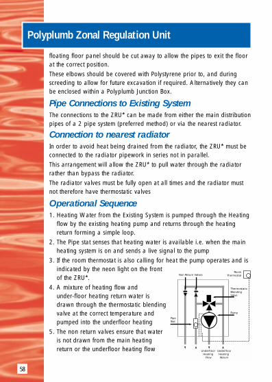
58
Polyplumb Zonal Regulation Unit
floating floor panel should be cut away to allow the pipes to exit the floorat the correct position.These elbows should be covered with Polystyrene prior to, and duringscreeding to allow for future excavation if required. Alternatively they canbe enclosed within a Polyplumb Junction Box.
Pipe Connections to Existing SystemThe connections to the ZRU* can be made from either the main distributionpipes of a 2 pipe system (preferred method) or via the nearest radiator.
Connection to nearest radiatorIn order to avoid heat being drained from the radiator, the ZRU* must beconnected to the radiator pipework in series not in parallel.This arrangement will allow the ZRU* to pull water through the radiatorrather than bypass the radiator.The radiator valves must be fully open at all times and the radiator mustnot therefore have thermostatic valves
Operational Sequence1. Heating Water from the Existing System is pumped through the Heating
flow by the existing heating pump and returns through the heatingreturn forming a simple loop.
2. The Pipe stat senses that heating water is available i.e. when the mainheating system is on and sends a live signal to the pump
3. If the room thermostat is also calling for heat the pump operates and isindicated by the neon light on the frontof the ZRU*.
4. A mixture of heating flow andunder-floor heating return water isdrawn through the thermostatic blendingvalve at the correct temperature andpumped into the underfloor heating
5. The non return valves ensure that wateris not drawn from the main heatingreturn or the underfloor heating flow
PipeStat
ThermostaticBlendingValve
Pump
Non Return Valves
UnderfloorHeating Return
Underfloor Heating
Flow
RoomThermostat

59
Polyplumb Zonal Regulation Unit
6. As the room reaches temperature, the room thermostat will break thelive signal to the pump and stop the pump from operating
7. As the boiler shuts downs and the main heating flow cools, the pipe statwill break the live signal to the pump and stop the pump from operating
User ControlsRoom ThermostatSets the high limit temperature in the room
Thermostatic Blending ValveSets the water temperature to the Underfloor heating. This needs to be setat 50 deg C (between setting 4 and 5) for solid floors and at 60 deg C(Max setting for floating and suspended floors
Pump Speed ControlThis will only need to be set at the lowestsetting (speed 1)
Pipe StatThe temperature shown on the dial is thetemperature which needs to exist in themain flow pipe from the heating to makethe unit operate the pump. This thereforesets the response time for the underfloor heating to operate after the mainheating is on.
In some systems where the existing heating pump pressure at the unit ispoor this may need to be set as low as 30 to 35 Deg C. Alternatively,where temperature at this control is reached soon after the heating systemis switched on, this can be set higher.
This control will also determine the period of time after the heating systemis switched off that the unit stops operating, if initial flow to the pipe statfrom the existing heating system is poor, some radiators on the samecircuit may need to be balanced to encourage flow to the unit.
PipeStat
ThermostaticBlendingValve
PumpSpeed Control
RoomThermostat

60
Polyplumb Underfloor Central Heating Systems
PRODUCT DESCRIPTION CODE NO.
Barrier Pipe Coils15mm x 100 metre coil PB10015B15mm x 150 metre coil PB15015B18mm x 120 metre coil PB12018B18mm x 200 metre coil PB20018B18mm x 300 metre coil PB30018B
Conduit Pipe Coils15mm x 25 metre Coil CPC152515mm x 50 metre Coil CPC155022mm x 25 metre Coil CPC222522mm x 50 metre Coil CPC2250
Pipe Dispenser PB03111
Pipe Stiffener(Must be used with Polybutylene Pipe)15mm Pipe Support PB6415
Edge Insulation25 metre Coil Edge Insulation PB05855
Standard UFCH Pipe Clip PB02911
Long Radius Bend FormerFor use as pipe guide at bottom of PB6325manifold - accepts 15mm conduit pipe
Featuring“Plumb
Straight”Coiling
Technology
Pipe stiffeners must be used whenever Polybutylene pipe is jointed into a Polyplumb socketed fitting or a compression fitting.

61
Polyplumb Underfloor Central Heating Systems
PRODUCT DESCRIPTION CODE NO.
Pipe CuttersStandard Type Cutter 10mm to 28mm PB777Replacement Blades for Standard Cutter PB780
Ratchet Type Cutter 10mm to 28mm PB778
Replacement Blades for Ratchet Cutter PB779
Floor Panel (1200mm x 1000mm) Floor Panel for Screeded Floors PB08576allow for overlap and waste when ordering
Floor Panel (1.2m x 1.2m x 50mm)10 Pack = 14.4 square metres(effective floor area)
Floating Floor Panel PB08577
Single Heat Spreader Plate(For 15mm and 18mm Pipe)Single Heat Spreader Plate PB207
Double Heat Spreader Plate(For 15mm and 18mm Pipe, 450 spandouble indent. Sets pipes at 300mm centres)Double Heat Spreader Plate PB209
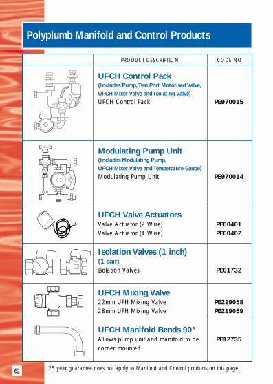
PRODUCT DESCRIPTION CODE NO.
UFCH Control Pack(Includes Pump,Two Port Motorised Valve,UFCH Mixer Valve and Isolating Valve)UFCH Control Pack PB970015
Modulating Pump Unit(Includes Modulating Pump,UFCH Mixer Valve and Temperature Gauge)Modulating Pump Unit PB970014
UFCH Valve ActuatorsValve Actuator (2 Wire) PB00401Valve Actuator (4 Wire) PB00402
Isolation Valves (1 inch)(1 pair)Isolation Valves PB01732
UFCH Mixing Valve22mm UFH Mixing Valve PB21905828mm UFH Mixing Valve PB219059
UFCH Manifold Bends 90°Allows pump unit and manifold to be PB12735corner mounted
62
Polyplumb Manifold and Control Products
25 year guarantee does not apply to Manifold and Control products on this page.

63
Polyplumb Manifold and Control Products
PRODUCT DESCRIPTION CODE NO.
15mm Manifold (C/W MountingBrackets, Drain Cock & Air Bleed)15mm Manifold - 2 Port PB1273715mm Manifold - 3 Port PB1273815mm Manifold - 4 Port PB1273915mm Manifold - 5 Port PB1274015mm Manifold - 6 Port PB1274115mm Manifold - 7 Port PB1274215mm Manifold - 8 Port PB1274315mm Manifold - 9 Port PB1274415mm Manifold - 10 Port PB1274515mm Manifold - 11 Port PB1274615mm Manifold - 12 Port PB12747
18mm Manifold (C/W MountingBrackets, Drain Cock & Air Bleed)18mm Manifold - 2 Port PB0835118mm Manifold - 3 Port PB0839218mm Manifold - 4 Port PB0845918mm Manifold - 5 Port PB0846218mm Manifold - 6 Port PB0847918mm Manifold - 7 Port PB0855818mm Manifold - 8 Port PB0856318mm Manifold - 9 Port PB0856418mm Manifold - 10 Port PB0857218mm Manifold - 11 Port PB0858818mm Manifold - 12 Port PB08589
Zonal Regulation Unit (ZRU)Mark TwoNew compact unit, supplied without PB970018cover, now features new PolyFit demountable connections
Compression
End
Compression
End
25 year guarantee does not apply to Manifold and Control products on this page.
Push-Fit Ends
Push-Fit Ends

64
Polyplumb Manifold and Control Products
PRODUCT DESCRIPTION CODE NO.
Surface Distribution BoxSurface Distribution Box - 4 Port PB06529Surface Distribution Box - 7 Port PB06530Surface Distribution Box - 10 Port PB06531Surface Distribution Box - 12 Port PB06532
Flush Distribution BoxFlush Distribution Box - 4 Port PB04401Flush Distribution Box - 7 Port PB04402Flush Distribution Box - 10 Port PB04404Flush Distribution Box - 12 Port PB04408
Zonal Regulation Unit (ZRU)for single room extensions and conservatories up to 25m2 PB970016
Zonal Regulation Unit (ZRU)White uPVC, designed to conceal PB970016entry and pipework underneathPolyplumb ZRU
Wiring Centrefor use with two wire adaptors PB23010
25 year guarantee does not apply to products on this page.

Installation Guide&Product Handbook
POLYPIPEBUILDING
PRODUCTS LTD
COLD WATERSUPPLY
SYSTEMSincorporating
MDPE Coiled PipePolysure Pipe
Polyfast Compression FittingsPush-fit Fittings
Polyfast AdaptorsElectrofusion Fittings
65

MDPE COILED PIPE
66

67
Polyethylene Pressure Pipe 20mm to 63mm OD20mm to 63mm PipeApplications
Blue MDPE pipes 20mm to 63mm toBS6572 are used for Potable WaterUnderground as service connectionsfrom distribution mains to individualproperties and are connected usingPolypipe Push-fit push-fit, Polyfastcompression fittings or electrofusionfittings. Blue pipes may also be usedfor above ground services if the pipesare installed within protective ducts.
Black MDPE pipes 20mm to 63mm toBS6730 are used for Potable WaterAbove Ground and are connectedusing Push-fit, Polyfast compressionfittings or electrofusion fittings.
Black LDPE continues to bemanufactured in accordance with the now obsolete BS1972 specification,for replacement pipe requirements, irrigation systems, and otherspecialised needs including the Export market and are connected usingPolyfast compression fittings in conjunction with the appropriate BS 1972adaptors.
Quality AssurancePolypipe operates a comprehensive quality assurance system toBS EN ISO 9002:1994 which has been formally approved bythe British Standards Institution and has 12 BSI KitemarkLicences. Polypipe is a BSI registered firm of assessed capabilityfor all manufactured products.
StandardsAll MDPE pipes have true metric outside diameters to ISO 161/1 (BS 5556)
Blue MDPE pipes in the diameter range 20mm to63mm are produced to BS6572:1985 (previously WRCIGN 4-32-02) and are Kitemarked.
FM00318
BS6572BS6730
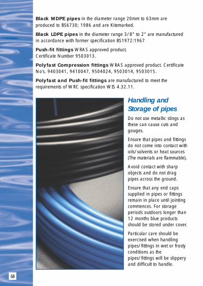
68
Black MDPE pipes in the diameter range 20mm to 63mm areproduced to BS6730; 1986 and are Kitemarked.
Black LDPE pipes in the diameter range 3/8" to 2" are manufacturedin accordance with former specification BS1972:1967
Push-fit fittings WRAS approved product. Certificate Number 9503013.
Polyfast Compression fittings WRAS approved product. CertificateNo’s. 9403041, 9410047, 9504024, 9503014, 9503015.
Polyfast and Push-fit fittings are manufactured to meet therequirements of WRC specification WIS 4.32.11.
Handling andStorage of pipesDo not use metallic slings asthese can cause cuts andgouges.
Ensure that pipes and fittingsdo not come into contact withoils/solvents or heat sources(The materials are flammable).
Avoid contact with sharpobjects and do not dragpipes across the ground.
Ensure that any end capssupplied in pipes or fittingsremain in place until jointingcommences. For storageperiods outdoors longer than12 months blue productsshould be stored under cover.
Particular care should beexercised when handlingpipes/fittings in wet or frostyconditions as thepipes/fittings will be slipperyand difficult to handle.
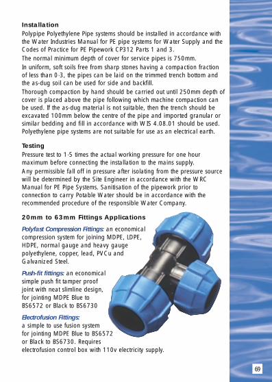
69
InstallationPolypipe Polyethylene Pipe systems should be installed in accordance withthe Water Industries Manual for PE pipe systems for Water Supply and theCodes of Practice for PE Pipework CP312 Parts 1 and 3.The normal minimum depth of cover for service pipes is 750mm.In uniform, soft soils free from sharp stones having a compaction fractionof less than 0·3, the pipes can be laid on the trimmed trench bottom andthe as-dug soil can be used for side and backfill.Thorough compaction by hand should be carried out until 250mm depth ofcover is placed above the pipe following which machine compaction canbe used. If the as-dug material is not suitable, then the trench should beexcavated 100mm below the centre of the pipe and imported granular orsimilar bedding and fill in accordance with WIS 4.08.01 should be used.Polyethylene pipe systems are not suitable for use as an electrical earth.
TestingPressure test to 1·5 times the actual working pressure for one hourmaximum before connecting the installation to the mains supply.Any permissible fall off in pressure after isolating from the pressure sourcewill be determined by the Site Engineer in accordance with the WRCManual for PE Pipe Systems. Sanitisation of the pipework prior toconnection to carry Potable Water should be in accordance with therecommended procedure of the responsible Water Company.
20mm to 63mm Fittings Applications
Polyfast Compression Fittings: an economicalcompression system for joining MDPE, LDPE,HDPE, normal gauge and heavy gaugepolyethylene, copper, lead, PVCu andGalvanized Steel.
Push-fit fittings: an economicalsimple push fit tamper proofjoint with neat slimline design,for jointing MDPE Blue toBS6572 or Black to BS6730
Electrofusion Fittings: a simple to use fusion systemfor jointing MDPE Blue to BS6572or Black to BS6730. Requireselectrofusion control box with 110v electricity supply.

70
PRODUCT DESCRIPTION CODE NO.
MDPE Blue PE80 12 Bar Pipe20mm x 25 metre Plain End Coil 2025BU20mm x 50 metre Plain End Coil 2050BU20mm x 100 metre Plain End Coil 20100BU20mm x 150 metre Plain End Coil 20150BU
25mm x 25 metre Plain End Coil 2525BU25mm x 50 metre Plain End Coil 2550BU25mm x 100 metre Plain End Coil 25100BU25mm x 150 metre Plain End Coil 25150BU
32mm x 25 metre Plain End Coil 3225BU32mm x 50 metre Plain End Coil 3250BU32mm x 100 metre Plain End Coil 32100BU32mm x 150 metre Plain End Coil 32150BU
50mm x 25 metre Plain End Coil 5025BU50mm x 50 metre Plain End Coil 5050BU50mm x 100 metre Plain End Coil 50100BU50mm x 150 metre Plain End Coil 50150BU
63mm x 25 metre Plain End Coil 6325BU63mm x 50 metre Plain End Coil 6350BU63mm x 100 metre Plain End Coil 63100BU63mm x 150 metre Plain End Coil 63150BU
MDPE Black PE80 12 Bar Pipe20mm x 25 metre Plain End Coil 2025B20mm x 50 metre Plain End Coil 2050B20mm x 100 metre Plain End Coil 20100B20mm x 150 metre Plain End Coil 20150B
25mm x 25 metre Plain End Coil 2525B25mm x 50 metre Plain End Coil 2550B25mm x 100 metre Plain End Coil 25100B25mm x 150 metre Plain End Coil 25150B
32mm x 25 metre Plain End Coil 3225B32mm x 50 metre Plain End Coil 3250B32mm x 100 metre Plain End Coil 32100B32mm x 150 metre Plain End Coil 32150B
40mm x 150 metre Plain End Coil ❉ 40100B
Blue & Black Polyethylene Pipe 20mm to 63mm OD
BS6572
BS6730
❉ 40mm pipes are currentlyonly included in the
Draft EuropeanStandard. pr EN12201

71
PRODUCT DESCRIPTION CODE NO.
continuedMDPE Black PE80 12 Bar Pipe50mm x 25 metre Plain End Coil 5025B50mm x 50 metre Plain End Coil 5050B50mm x 100 metre Plain End Coil 50100B50mm x 150 metre Plain End Coil 50150B
63mm x 25 metre Plain End Coil 6325B63mm x 50 metre Plain End Coil 6350B63mm x 100 metre Plain End Coil 63100B63mm x 150 metre Plain End Coil 63150B
MDPE Black PE80 6 Bar Pipe50mm x 100 metre Plain End Coil 5006100B63mm x 100 metre Plain End Coil 6306100B
LDPE Black Type 32, 9 Bar Pipe3/8” x 25 metre Plain End Coil 3825LC3/8” x 50 metre Plain End Coil 3850LC3/8” x 100 metre Plain End Coil 38100LC3/8” x 150 metre Plain End Coil 38150LC
1/2” x 25 metre Plain End Coil 1225LC1/2” x 50 metre Plain End Coil 1250LC1/2” x 100 metre Plain End Coil 12100LC1/2” x 150 metre Plain End Coil 12150LC
3/4” x 25 metre Plain End Coil 3425LC3/4” x 50 metre Plain End Coil 3450LC3/4” x 100 metre Plain End Coil 34100LC3/4” x 150 metre Plain End Coil 34150LC
1” x 25 metre Plain End Coil 10025LC1” x 50 metre Plain End Coil 10050LC1” x 100 metre Plain End Coil 100100LC1” x 150 metre Plain End Coil 100150LC
Blue & Black Polyethylene Pipe 20mm to 63mm OD
For sizes 75mm OD to 450 OD MDPE and HPPE Pipes & Fittings telephone Polypipe MDPE Sales on: 01709 770000

POLYSURE PIPE
72

73
Polysure Pipe 15mm, 22mm and 28mm
Polysure service pipes are copper pipes with anexternal protective sheath of polyethylene and areused where service pipeshave to be installed incontaminated ground asoften occurs when formerindustrial sites are used forhouse building.
The WRC manual for polyethylenepipe systems and the service pipemanual recommend thatpolyethylene must not be used incontaminated grounds whereorganic chemicals through the pipewall could result in contamination ofthe potable water within thepipeline. In these circumstances, themanuals recommend that metal pipes should be installedwherever ground contamination is present.
The Copper pipes are produced to EN1057-R220 and the bluepolyethylene sheath complies with BS 3412. The externalcoating of polyethylene protects the copper pipe from externalcorrosion and improves the resistance of the pipe to mechanicaldamage. The following dimensions are available.
Pipe diameter OD (mm)
Plastic outer layer 17 24 32
Copper inner layer 15 22 28

To join adjacent lengths of Polysure pipes,proprietary gunmetal or DZR Brass fittings must beused (not supplied by Polypipe) to connect theCopper pipes to polyethylene pipes to BS6572,Polyfast or Push-fit copper adaptor couplers shouldbe used. (Polyfast code: 478, Push-fit code: 378)
1. Make a circular incision cutting through theplastic outer protective cover.
1. Remove the cut plastic from the end of the tube.The plastic cover should be cut back sufficiently topermit insertion into the coupling and sufficientcopper tube should be exposed to enable thePolysure pipe to enter up to the stop in the bodyof the fitting.
2. Cut the copper inner pipe using proprietry pipewheel cutters. Do not use a hacksaw unless greatcare is taken to remove any burrs from bothinside and outside the pipe.
3. Re-round the end of the pipe for ease of entryusing a re-rounding tool.
4. Fully push home the copper pipe into thePolyplumb socket through both the ‘O’ ring sealand the stainless steel grabring.
5. Finally wrap each end of the joint created with asuitablewaterproofadhesive plastictape for the last25mm or so ofplastic coveringand a similarlength immediatelyadjacent to thecopper tube.
JointingInstructions
74
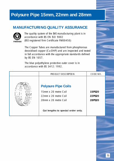
75
Polysure Pipe 15mm, 22mm and 28mm
PRODUCT DESCRIPTION CODE NO.
Polysure Pipe Coils
15mm x 20 metre Coil 15PS2022mm x 20 metre Coil 22PS2028mm x 20 metre Coil 28PS20
Cut lengths to special order only.
MANUFACTURING QUALITY ASSURANCE
The quality system of the IMI manufacturing plant is in accordance with BS EN ISO 9002 (BSI registered firm Certificate FM00450)
The Copper Tubes are manufactured from phosphorousdeoxidised copper (Cu-DHP) and are inspected and testedin full accordance with the appropriate standards definedby BS EN 1057.
The blue polyethylene protective outer cover is inaccordance with BS 3412: 1992.
FM00450

POLYFAST FITTINGS
76

77
Polyfast Polyethylene Compression Fittings
Compression Fittings in sizes 20mm to 63mm OD, to the requirements of WRC WIS 4.32.11. ADAPTABLE FOR POLYETHYLENE, LEAD, COPPER, PVC AND GALVANISED IRON20mm to 63mm. MDPE to BS6572 and BS6730,& 3/8 inch to 2 inch LDPE to BS1972:1967 Class C and D,HDPE to BS3284:1967 Class C and D, LDPE to BS1972:1961Normal and Heavy Gauge (IS134-1977),Copper to BS2871 Table X and Y BS659, BS1386, Lead toBS602/1085:1970, PVC to BS3505:1986, Galvanised Steel to BS1387:1985.
MATERIALS: Polyfast compression fittings are manufacturedwith engineering plastic bodies and grab ringswith EPDM Rubber seals kitemarked toBS EN681-1and engineering plastic stiffenersand retaining nuts.
FEATURES: ● Sound joint integrity gives reliable trouble freeservice.
● Simple and quick to use for speedy installation.● PN16 Pressure Rating gives increased safety
factor.● Pipe and fittings from one British manufacturer.● End load resistant – pull out is prevented by
grab ring/pipe stiffener/insert.● Body and nut adaptable to different pipes.● Robust high impact resistance.● Tough to withstand damage even at low
temperatures.● Seals are pre-lubricated.

78
Note: Always check that the factory appliedsilicone lubricant grease is present on therubber seal.There are 5 Vital stages tosuccessfully join PolyfastCompression fittings to blue (BS6572)and black (BS6730) MDPE pipe.
1. Always use one of the approved pipecutters (Code 781 or 778). A slight rotation of the pipe when cuttingwill help make the operation easier.Never use a hacksaw. Cut pipe endsquare and remove any burrs or sharpedges.
2. Insert pipe stiffener in pipe up to the stop.
3. Loosen nut on Polyfast fittings.
4. Insert clean pipe to full socket depth andre-hand tighten the polyfast nut to secure,plus 1/8 of a turn using a strap wrench(Code: 780) Do not over tighten.Polyethylene pipe cannot be used as anelectrical earth.
Hand tighten plus 1/8 turn using strap wrench.
Polyethylene Pipe JointingInstructions
JointingInstructions

MDPE Reducing Set(a) Remove nut from fitting and place over pipe end.
(b) Discard black/grey metric grab ring.
(c) Place nut reducer and new black grab ring over pipe end (thickest section towards fitting body) Ensure the grab ringis positioned at the end of the pipe.
(d) Insert barbed end of adaptor into pipe and tap in with wooden mallet up to flange.
(e) Push black grab ring up to flange, if necessary.
(f) Push spigot end of adaptor into body of fitting to full socketdepth. Engage nut onto fitting.
(g) Hand tighten plus 1/8 turn using strap wrench.
LDPE and HDPE Black BS1972: 1967 C&D BS3284 C&D BS1972: 1961 (IS134 NG & HG)
(a) Remove nut from fitting and place over pipe end.
(b) Discard black/grey metric grab ring.
(c) Place white imperial grab ring over pipe (thickest section towards fitting body). Ensure the grab ring is positioned atthe end of the pipe.
(d) Insert barbed end of adaptor into pipe and tap in with wooden mallet up to flange.
(e) Push spigot end of adaptor into body of fitting to full socketdepth. Engage nut onto fitting.
(f) Hand tighten plus 1/8 turn using strap wrench.
79
Polyfast Adaptor Set Jointing Instructions
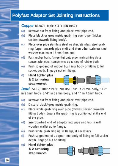
80
Copper BS2871 Table X & Y (EN1057)
(a) Remove nut from fitting and place over pipe end.(b) Place black or grey metric grab ring over pipe (thickest
section towards fitting body).(c) Place over pipe stainless steel washer, stainless steel grab
ring (taper towards pipe end) and then other stainless steelwasher maximum 15mm from end.
(d) Push rubber bush, flange first onto pipe, maintaining closecontact with other components up to stop of rubber bush.
(e) Push spigot end of rubber bush into body of fitting to fullsocket depth. Engage nut on fitting.
(f) Hand tighten plus 1/2 turn using strap wrench.
Lead BS602, 1085/1970 NB Use 3/8” in 20mm body, 1/2”in 25mm body, 3/4” in 32mm body, and 1” in 40mm body.
(a) Remove nut from fitting and place over pipe end.(b) Discard black/grey metric grab ring.(c) Place white grab ring over pipe (thickest section towards
fitting body). Ensure the grab ring is positioned at the endof the pipe.
(d) Insert barbed end of adaptor into pipe and tap in with wooden mallet up to flange.
(e) Push white grab ring up to flange, if necessary.(f) Push spigot end of adaptor into body of fitting to full socket
depth. Engage nut on fitting.(g) Hand tighten plus
1/2 turn using strap wrench.
Polyfast Adaptor Set Jointing Instructions

81
PVCu BS3505/6 1968 Galvanised Steel BS1387(a) Remove nut from fitting
and place over pipe end(b) Discard black metric split grab ring(c) Push rubber bush onto end of pipe(d) Push spigot end of rubber bush into body of fitting to full
socket depth. Engage nut onto fitting(e) Hand tighten plus 1/2 turn using strap wrench.NB: Not end load bearing. Must be anchored to prevent pullout.
Imperial Adaptor Couplers for LDPE/HDPE PipesBS 1972: 1967/BS 3284: 1967
(a) Note that the imperial end of the fitting has a Black nut.Cut the pipe end square with the axis and file a chamferonto thge pipe end.
(b) Insert the pipe end through the black nut, grab-ring and therubber seal to full socket depth.
(c) Hand tighten plus 1/8 turn using strap wrench.(Note: Do not over tighten).
Wide Tolerance Adaptor Couplers for Lead PipesBS 602, 1085: 1970
(a) Check condition of pipe surface and cut back pip square toremove any surface grooves or damage using pipe cutters orsaw, deburr and chamfer end of pipe to facilitate assembly.
(b) Remove the nut from the fitting and replace the nut over thepipe end.
(c) Mark the socket depth on the pipe and push the grab-ringup to the mark (thickest section toward fitting body).
(d) Push the seal onto the pipe and up to the grab-ring (taperedface towards fitting).
(e) Position the lead pipe, seal and grab-ring into the fittingbody, engage the thread.
(f) Hand tighten plus 1/4 turn using strap wrench.(Note: Do not over tighten).
Polyfast Adaptor Set Jointing Instructions
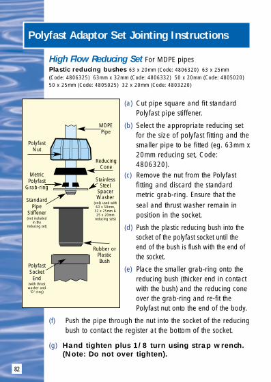
82
High Flow Reducing Set For MDPE pipesPlastic reducing bushes 63 x 20mm (Code: 4806320) 63 x 25mm (Code: 4806325) 63mm x 32mm (Code: 4806332) 50 x 20mm (Code: 4805020) 50 x 25mm (Code: 4805025) 32 x 20mm (Code: 4803220)
(a) Cut pipe square and fit standardPolyfast pipe stiffener.
(b) Select the appropriate reducing setfor the size of polyfast fitting and thesmaller pipe to be fitted (eg. 63mm x20mm reducing set, Code:4806320).
(c) Remove the nut from the Polyfastfitting and discard the standardmetric grab-ring. Ensure that theseal and thrust washer remain in position in the socket.
(d) Push the plastic reducing bush into thesocket of the polyfast socket until theend of the bush is flush with the end ofthe socket.
(e) Place the smaller grab-ring onto thereducing bush (thicker end in contactwith the bush) and the reducing coneover the grab-ring and re-fit thePolyfast nut onto the end of the body.
(f) Push the pipe through the nut into the socket of the reducingbush to contact the register at the bottom of the socket.
(g) Hand tighten plus 1/8 turn using strap wrench.(Note: Do not over tighten).
Polyfast Adaptor Set Jointing Instructions
PolyfastNut
MetricPolyfast
Grab-ring
StandardPipe
Stiffener(not included
in thereducing set)
PolyfastSocketEnd
(with thrustwasher and
‘O’-ring)
MDPEPipe
ReducingCone
Rubber orPlasticBush
StainlessSteel
SpacerWasher
(only used with63 x 50mm,
32 x 25mm &25 x 20mm
reducing sets)

83
Polyfast Adaptor Set Jointing Instructions
High Flow Reducing Set For MDPE pipes
Rubber bushes 63 x 50mm (Code: 4806350) 32 x 25mm (Code: 4803225) 25mm x 20mm (Code: 4802520)
(a) Cut pipe square and fit standard Polyfast pipe stiffener.
(b) Select the appropriate reducing set for the size of polyfastfitting and the smaller pipe to be fitted (eg. 63mm x 20mmreducing set, Code: 4806320).
(c) Remove the nut from the Polyfast fitting and discard thestandard metric grab-ring. Ensure that the seal and thrustwasher remain in the position in the socket and check thatthe factory applied silicone lubricant grease is present onthe rubber seal.
(d) Place the nut on the pipe end followed by the reducingcone, grab-ring (thickest section towards the pipe end) andstainless steel support washer.
(e) Fit the rubber bush over the pipe end and push the stainlesssteel washer/grab-ring and reducing cone back down thepipe until the pipe is fully inserted into the rubber bush witha stainless steel spacer washer and grab-ring in contactwith the flanged end of the rubber bush.
(f) Push the plain spigot of the rubber reducing bush into thesocket of the fitting through the thrust washer and ‘O’-ring andengage the nut onto the threads on the body of the fitting.
(g) Hand tighten plus 1/8 turn using strap wrench.(Note: Do not over tighten).

84
Polyfast Adaptor Set Jointing Instructions
Copper/Polybutylene SocketsPolyfast MDPE x Copper/polybutylene adaptors (Code: 478) andPush-fit MDPE x Copper/polybutylene adaptors (Code: 378)
Please refer to the jointing and dismantlinginstruction section of the Polyplumb Hot and ColdWater Plumbing and Heating Guide earlier in thismanual (pages 8, 9 and 10).
Slip Repair Couplers To replace damaged pipe on straight runs
(a) Cut out the damaged pipe for a distance of at least thelength of 2 slip couplers. Cut a replacement length of pipe,and deburr/chamfer pipe ends.
(b) Fit pipe stiffeners to pipe ends and mark half the length ofthe slip couplers from each pipe end with a felt-tipped pen.Remove nuts and grab rings from the 2 slip couplers andplace first one nut and one grab ring on the existing pipeends with the tapers as shown.
(c) Check that the ‘O’-ring seals are lubricated and slide oneslip coupler onto each pipe end, holding the thrust washerand ‘O’-ring in place until the couplers are fully onto thepipe ends.
(d) Place the second nut and grab-ring of each slip coupleronto the replacement length of pipe as shown, insert thereplacement length of pipe inbetween the 2 existingpipe ends.

85
(e) Slide the 2 slip couplersonto the replacementpipe so that they arehalf on the existingpipe and half on thereplacement pipe usingthe previously markedlines for guidance.
If neccessary, ensurethat the seals and thrustwashers are pushedback into position ineach socket.
(f) Slide the grab-ringsback to contact the endof each socket. (It maybe necessary to insertthe end of ascrewdriver or a pieceof wood in the grab-ring slot to open thegrab-ring out slightly toenable it to be movedbackwards).
(g) Screw the nuts ontoeach socket end. Hand tighten plus 1/8 of a turn with astrap-wrench.
“O” Ring
Grab Ring
PipeStiffeners
Replacement Pipe
ThrustWasher
Slip RepairCoupler
Nut
Slip Repair Couplers continued
Polyfast Adaptor Set Jointing Instructions

86
PRODUCT DESCRIPTION CODE NO.
Straight Coupler20mm Straight Coupler 4002025mm Straight Coupler 4002532mm Straight Coupler 4003240mm Straight Coupler 4004050mm Straight Coupler 4005063mm Straight Coupler 40063
Slip/Repair Coupler20mm Slip/Repair Coupler 40020S25mm Slip/Repair Coupler 40025S32mm Slip/Repair Coupler 40032S40mm Slip/Repair Coupler 40040S50mm Slip/Repair Coupler 40050S63mm Slip/Repair Coupler 40063S
Reducing Coupler25mm x 20mm Reducing Coupler 4062532mm x 20mm Reducing Coupler 406322032mm x 25mm Reducing Coupler 4063240mm x 32mm Reducing Coupler 4064050mm x 32mm Reducing Coupler 406503250mm x 40mm Reducing Coupler 40650
Metric to Imperial Coupler20mm x 1⁄2” 4812025mm x 1⁄2” 481251225mm x 3⁄4” 48125
Copper/Polybutylene Coupler20mm x 15mm (1⁄2”) Copper Coupler 4782025mm x 15mm (1⁄2”) Copper Coupler 478251525mm x 22mm (3⁄4”) Copper Coupler 4782532mm x 22mm (3⁄4”) Copper Coupler 478322232mm x 28mm (1”) Copper Coupler 47832
Polyfast Polyethylene Compression Fittings
BS1972: 1967 & BS3284BS1972: 1967 & BS3284BS1972: 1967 & BS3284
The Copper/Polybutylenesocket is a Push-fit to
BS7291/2: 1990
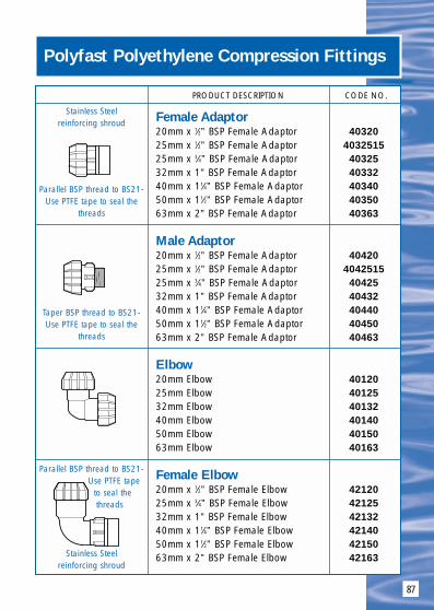
87
PRODUCT DESCRIPTION CODE NO.
Female Adaptor20mm x 1⁄2” BSP Female Adaptor 4032025mm x 1⁄2” BSP Female Adaptor 403251525mm x 3⁄4” BSP Female Adaptor 4032532mm x 1” BSP Female Adaptor 4033240mm x 11⁄4” BSP Female Adaptor 4034050mm x 11⁄2” BSP Female Adaptor 4035063mm x 2” BSP Female Adaptor 40363
Male Adaptor20mm x 1⁄2” BSP Female Adaptor 4042025mm x 1⁄2” BSP Female Adaptor 404251525mm x 3⁄4” BSP Female Adaptor 4042532mm x 1” BSP Female Adaptor 4043240mm x 11⁄4” BSP Female Adaptor 4044050mm x 11⁄2” BSP Female Adaptor 4045063mm x 2” BSP Female Adaptor 40463
Elbow20mm Elbow 4012025mm Elbow 4012532mm Elbow 4013240mm Elbow 4014050mm Elbow 4015063mm Elbow 40163
Female Elbow20mm x 1⁄2” BSP Female Elbow 4212025mm x 3⁄4” BSP Female Elbow 4212532mm x 1” BSP Female Elbow 4213240mm x 11⁄4” BSP Female Elbow 4214050mm x 11⁄2” BSP Female Elbow 4215063mm x 2” BSP Female Elbow 42163
Polyfast Polyethylene Compression Fittings
Stainless Steelreinforcing shroud
Parallel BSP thread to BS21-Use PTFE tape to seal the
threads
Stainless Steelreinforcing shroud
Parallel BSP thread to BS21-Use PTFE tape
to seal thethreads
Taper BSP thread to BS21-Use PTFE tape to seal the
threads

88
PRODUCT DESCRIPTION CODE NO.
Male Elbow20mm x 1⁄2” BSP Male Elbow 4232025mm x 3⁄4” BSP Male Elbow 42325
Wider Tolerance Lead Coupler25mm x 3⁄8” 5lb Lead 47938525mm x 1⁄2” 7lb Lead 47912725mm x 1⁄2” 9lb Lead 47912925mm x 3⁄4” 9lb Lead 47934932mm x 3⁄4” 11lb Lead 479341125mm x 1” 16lb Lead 479116
Equal Tee20mm Equal Tee 4022025mm Equal Tee 4022532mm Equal Tee 4023240mm Equal Tee 4024050mm Equal Tee 4025063mm Equal Tee 40263
Branch Reducing Tee25mm x 20mm Branch Reducing Tee 4112532mm x 25mm Branch Reducing Tee 41132
Female Branch Tee20mm x 1⁄2” BSP Female Branch Tee 4222025mm x 3⁄4” BSP Female Branch Tee 4222532mm x 1” BSP Female Branch Tee 4223240mm x 11⁄4” BSP Female Branch Tee 4224050mm x 11⁄2” BSP Female Branch Tee 4225063mm x 2” BSP Female Branch Tee 42263
Polyfast Polyethylene Compression Fittings
PE x Lead(includingStiffener)
Stainless Steelreinforcing shroud
Taper BSP thread to BS21-Use PTFE tape
to seal thethreads
Parallel BSP thread to BS21-UsePTFE tape to seal the threads
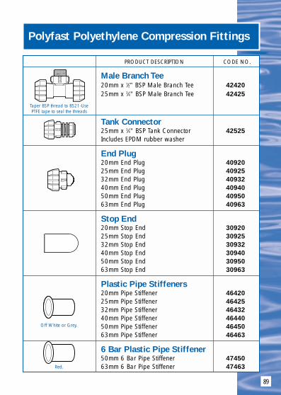
89
PRODUCT DESCRIPTION CODE NO.
Male Branch Tee20mm x 1⁄2” BSP Male Branch Tee 4242025mm x 3⁄4” BSP Male Branch Tee 42425
Tank Connector25mm x 3⁄4” BSP Tank Connector 42525Includes EPDM rubber washer
End Plug20mm End Plug 4092025mm End Plug 4092532mm End Plug 4093240mm End Plug 4094050mm End Plug 4095063mm End Plug 40963
Stop End20mm Stop End 3092025mm Stop End 3092532mm Stop End 3093240mm Stop End 3094050mm Stop End 3095063mm Stop End 30963
Plastic Pipe Stiffeners20mm Pipe Stiffener 4642025mm Pipe Stiffener 4642532mm Pipe Stiffener 4643240mm Pipe Stiffener 4644050mm Pipe Stiffener 4645063mm Pipe Stiffener 46463
6 Bar Plastic Pipe Stiffener50mm 6 Bar Pipe Stiffener 4745063mm 6 Bar Pipe Stiffener 47463
Polyfast Polyethylene Compression Fittings
Taper BSP thread to BS21-UsePTFE tape to seal the threads
Off White or Grey.
Red.
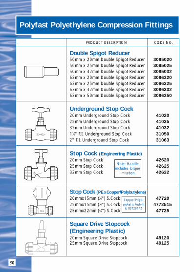
90
PRODUCT DESCRIPTION CODE NO.
Double Spigot Reducer 50mm x 20mm Double Spigot Reducer 308502050mm x 25mm Double Spigot Reducer 308502550mm x 32mm Double Spigot Reducer 308503263mm x 20mm Double Spigot Reducer 308632063mm x 25mm Double Spigot Reducer 308632563mm x 32mm Double Spigot Reducer 308633263mm x 50mm Double Spigot Reducer 3086350
Underground Stop Cock20mm Underground Stop Cock 4102025mm Underground Stop Cock 4102532mm Underground Stop Cock 4103211⁄2” F.I. Underground Stop Cock 310502” F.I. Underground Stop Cock 31063
Stop Cock (Engineering Plastic)20mm Stop Cock 4262025mm Stop Cock 4262532mm Stop Cock 42632
Stop Cock (PExCopper/Polybutylene)20mmx15mm (1⁄2”) S.Cock 4772025mmx15mm (1⁄2”) S.Cock 477251525mmx22mm (3⁄4”) S.Cock 47725
Square Drive Stopcock(Engineering Plastic)20mm Square Drive Stopcock 4912025mm Square Drive Stopcock 49125
Polyfast Polyethylene Compression Fittings
Note: Handleincludes torque
limitation.
Copper/Polyb. socket is Push-fit
to BS7291/2

91
PRODUCT DESCRIPTION CODE NO.
Double Check Valve20mm Double Check Valve 4762025mm Double Check Valve 4762532mm Double Check Valve 47632
Single Union Ball Valve1⁄2” F.I. Single Union Ball Valve 473121⁄2” F.I. Single Union Ball Valve 473341” F.I. Single Union Ball Valve 473111⁄2” F.I. Single Union Ball Valve 4731122” F.I. Single Union Ball Valve 4732
Swivel Adaptor20mm x 1⁄2” Swivel Adaptor 4752025mm x 1⁄2” Swivel Adaptor 475251225mm x 3⁄4” Swivel Adaptor 4752525mm x 1” Swivel Adaptor 47525132mm x 1” Swivel Adaptor 4753232mm x 11⁄4” Swivel Adaptor 47532114
Threaded Reducing Bush3⁄4” x 1⁄2” BSP Threaded Reducing Bush 47034121” x 1⁄2” BSP Threaded Reducing Bush 4701121” x 3⁄4” BSP Threaded Reducing Bush 47013411⁄4” x 1” BSP Threaded Reducing Bush 470114111⁄2” x 1⁄2” BSP Threaded Reducing Bush 4701121211⁄2” x 3⁄4” BSP Threaded Reducing Bush 4701123411⁄2” x 1” BSP Threaded Reducing Bush 470112111⁄2” x 1⁄4” BSP Threaded Reducing Bush 471121142” x 1⁄2” BSP Threaded Reducing Bush 4702122” x 3⁄4” BSP Threaded Reducing Bush 4702342” x 1” BSP Threaded Reducing Bush 470212” x 11⁄2” BSP Threaded Reducing Bush 47021123” x 2” BSP Threaded Reducing Bush 470324” x 3” BSP Threaded Reducing Bush 47043
Polyfast Polyethylene Compression Fittings
To adaptPolyfast
Socket toFemale BSP
SwivelCan also be used with Push-fit fittings
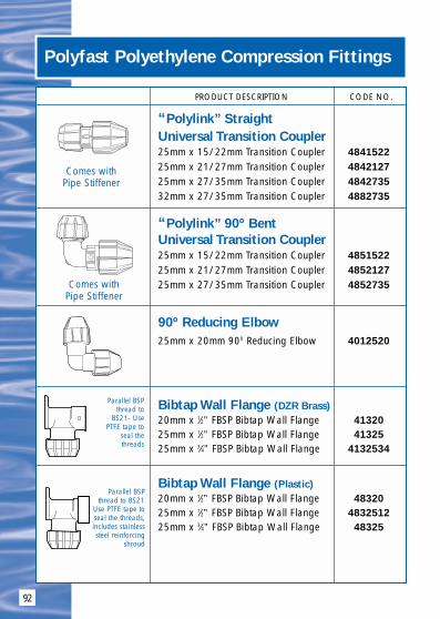
92
Polyfast Polyethylene Compression Fittings
PRODUCT DESCRIPTION CODE NO.
“Polylink” Straight Universal Transition Coupler25mm x 15/22mm Transition Coupler 484152225mm x 21/27mm Transition Coupler 484212725mm x 27/35mm Transition Coupler 484273532mm x 27/35mm Transition Coupler 4882735
“Polylink” 90º BentUniversal Transition Coupler25mm x 15/22mm Transition Coupler 485152225mm x 21/27mm Transition Coupler 485212725mm x 27/35mm Transition Coupler 4852735
90º Reducing Elbow25mm x 20mm 900 Reducing Elbow 4012520
Bibtap Wall Flange (DZR Brass)20mm x 1⁄2” FBSP Bibtap Wall Flange 4132025mm x 1⁄2” FBSP Bibtap Wall Flange 4132525mm x 3⁄4” FBSP Bibtap Wall Flange 4132534
Bibtap Wall Flange (Plastic)20mm x 1⁄2” FBSP Bibtap Wall Flange 4832025mm x 1⁄2” FBSP Bibtap Wall Flange 483251225mm x 3⁄4” FBSP Bibtap Wall Flange 48325
Parallel BSPthread to
BS21- UsePTFE tape to
seal thethreads
Parallel BSPthread to BS21
Use PTFE tape toseal the threads,includes stainlesssteel reinforcing
shroud
Comes withPipe Stiffener
Comes withPipe Stiffener

93
Polyfast Polyethylene Compression Fittings
PRODUCT DESCRIPTION CODE NO.
Imperial Polyethylenex Male Iron Coupler1/2” Imperial Polyethylene x Male Iron Coupler 49012
Imperial Polyethylenex Male Iron Coupler3/4” Imperial Polyethylene x Male Iron Coupler 49034
Imperial Polyethylenex Male Iron Coupler1” Imperial Polyethylene x Male Iron Coupler 4901

OVERLAY SYSTEM
94

95
Until now Under Floor Central Heating hasbeen strictly for new homes or as part of awhole-house refurbishment project. Previousufch Installation techniques caused significantdisruption to the home because of the need tore-excavate existing floors, and the timeconsuming connection to the central heatingboiler was often a major headache.
Now with Overlay Floor Heating Systemfrom Polypipe you can lay a simple ‘lowprofile’ panel system over the existing solid or timber floor in any room.And it can be linked to the existing radiator system via the PolyplumbZonal Regulation Unit (ZRU) or Distribution Multi-portManifold.
Overlay is quick to heat up to the required temperatureand energy efficient to run under any floor covering.Because the overlay panel system is high load bearingand impact resistant (and fire resistant and soundinsulating) it is the ideal base for wood or laminateflooring, for ceramic tiles, or for carpet.
floor covering
concrete sub-floor
Polyplumb12mm barrier pipe
Overlay floor panel
End Return
damp proofmembrane
under carpet
under wood orlaminate fooring
under tiles

96
Overlay System Product Range
Installation InstructionsStage 1 - Design & PlanningTo decide the orientation of the boards, the pipe runs are to be made inthe direction of the longest edge of the room with the return bends on theshortest walls. This ensures the minimum required amount of return bends.The first end returns and Overlay panel should be laid in the “best”square corner, ie with no obstacles. The positioning of the ZonalRegulation Unit (ZRU) or manifold is determined by the most convenientlocation of heating supply. On single circuit rooms the pipes can be run ina simplistic route up and down the room and the final return is run alongthe short edge of the room back to the ZRU / manifold.When the room floor dictates that more than one circuit is required, theOverlay system flow from the ZRU is taken to the furthest point and“worked back” to the unit to ensure the longest run is the warmest.Stage 2 - Floor LevellingThe installation of Overlay floor heating must be done on a level surfacewhich contains no dips or bumps. If the sub floor is not level and soundthis may result in damage to the Overlay floor panels. Use a self levellingcompound to fill any minor dips. Ensure the sub floor (solid concrete orsuspended timber) is thoroughly swept and all dirt, dust, grit and anyother residue is removed. Failure to do so will result in an uneven surface.Stage 3 - Floor / Drying and Perimeter SealingBefore commencing any installation work the sub floor must be dry. Careshould be taken around external doors and areas such as bathrooms andkitchens to ensure no damp is present. Check for damp and moistureingress into room and ensure fully sealed, eg with appropriate siliconesealant. All door thresholds should be checked for moisture ingress andwhere moisture is breaching the threshold this should be sealed withsilicone. Ensure the sub-floor has a DPC/DPM present and that walls areprotected by a damp proof course. Where there are alcoves for doorwaysit is recommended that these are sealed with silicone and filled in up tothe line of the wall using a plywood filler piece 18mm in depth. Any gapscan be taken up by a semi-dry concrete screed.Where there are any other small recesses or indents it is alsorecommended these are filled in to reduce the cutting of Overlay panels.Stage 4 - Skirting / Electrical Room CheckAll skirting boards should be removed before commencing installation.As the finished floor level will alter after the installation is complete andthe skirting board may be at a higher position, electrical sockets should bechecked for possible clashes with the new skirting height.
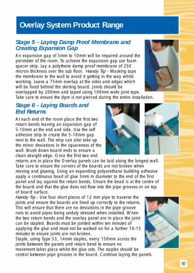
97
Overlay System Product Range
Stage 5 - Laying Damp Proof Membrane and Creating Expansion GapAn expansion gap of 5mm to 10mm will be required around theperimeter of the room. To achieve the expansion gap use foamspacer strip. Lay a polythene damp proof membrane of 250micron thickness over the sub floor. Handy Tip - Masking tapethe membrane to the wall to avoid it getting in the way whilstworking. Leave a 75mm overlap at the sides and edges whichwill be fixed behind the skirting board. Joints should beoverlapped by 200mm and taped using 100mm wide joint tape.Take care to ensure the dpm is not pierced during the entire installation.
Stage 6 - Laying Boards and End ReturnsAt each end of the room place the first tworeturn bends leaving an expansion gap of 5-10mm at the end and side. Use the selfadhesive strip to create the 5-10mm gapnext to the wall. The strip can also take upthe minor deviations in the squareness of thewall. Brush down board ends to ensure aclean straight edge. Once the first two endreturns are in place the Overlay panels can be laid along the longest wall.Take care to ensure the corners of the boards are not broken whenmoving and glueing. Using an expanding polyurethane building adhesiveapply a continuous bead of glue 3mm in diameter to the end of the firstpanel and lay against the return bends. Ensure the bead is at the centre ofthe board and that the glue does not flow into the pipe grooves or on topof board surface.Handy Tip - Use four short pieces of 12 mm pipe to traverse thejoints and ensure the boards are lined up correctly to the returns.This will ensure that there are no deviations in the pipe grooveruns to avoid pipes being unduly stressed when installed. Whenthe two return bends and the overlay panel are in place the jointcan be stapled. Boards must be jointed within ten minutes ofapplying the glue and must not be walked on for a further 10-15minutes to ensure joints are not broken.Staple, using Type 53, 14mm staples, every 150mm across thejoints between the panels and return bend to ensure nomovement takes place whilst the glue sets. The staples should becentral between pipe grooves in the board. Continue laying the panels

98
Overlay System Product Range
along the length of the room.Apply glue to the end of each panel only by butting up to each other onthe first run. Lay the rest of the end returns along the wall and work back.When nearing the end of the first run of panels allow for the return bendsand cut a panel to size to complete the run.
The Overlay panels can also be cut using a handsaw or electricjigsaw set at a slow speed. Use the remainder of the panel tostart the next run and stagger joints with the next set of panels.Ensure there is adequate ventilation to the room as layingOverlay floor panels can generate dust.Cover the area of the room with Overlay boards, ensuring gapsare left for expansion purposes around the perimeter.Use cut boards to start the next run to keep wastage to a minimum.Check for movement when laying boards and where the floor isnot completely level use self levelling granules and brush to fill anyminor dips.
Do not infill any small gaps in the floor area with Overlay panel off cuts. Inthese cases use a dry mix screed.Allow the glue to dry before carefully removing excess with a chisel.Handy Tip - If there is any dried glue in any of the pipe grooves at paneljoints use a short offcut of 12mm pipe to remove any excess glue byscraping out. Use a vacuum cleaner and a small brush to remove all dustand debris from the pipe grooves prior to fitting pipes into the grooves.
Stage 7 - Installing PipeInstall the 12mm polybutylene barrier pipeinto the Overlay panels.The pipe is a “size-for-size” fit into thegrooves and care should be taken to avoidkinking the pipes. A soft head mallet can beused to tap the pipes carefully into thegrooves if necessary. Observe all normalprocedures associated with the installation ofPolyplumb pipes (see Polyplumb Design andInstallation Guide). Allow for enough pipe at
the start and end of each circuit to connect to the distribution unit (eg aPolyplumb ZRU). Use the self adhesive pipe clip to clip flow and returnpipes at the sides/ends of rooms. Do not use nail down clips to secure pipesas the polythene dpm must not be pierced.Stage 8 - Connecting PipeConnect pipes to Polyplumb ZRU (if used) using a 15mm x 12mm brassadaptor. Multiple circuits can be accommodated by using 15mm

99
Overlay System Product Range
Polyplumb tees and elbows. Observe all normal installation procedureswhen installing Polyplumb pipes and fittings. The system can beconnected to the ZRU. Fill and pressure test the system inaccordance with the Polyplumb Design and Installation Guide.Cover pipes entering and exiting the ZRU using the ZRU PipeShroud.Stage 9 - Finishing PerimetersFill in the void containing flow and return pipes with a semi dryscreed of concrete which contains a plasticiser to the level ofthe top Overlay floor panel.Stage 10 - Covering the FloorTiles or wood/laminate floor can be applied directly over theOverlay floor heating system. It is recommended that a 4mmwaterproof plywood cover is installed over the Overlay panels and pipeswhen the finished floor is to be carpeted. Mark on the plywoodcovering where the pipe runs are. Staple plywood to theOverlay panel ensuring not to staple through pipes. Handy tip -Mark a strip of wood with the pipe centres on and use to slideacross the plywood, stapling between the marks.All plywood joints should be taped. Once the floor covering has been applied the skirting boardcan be fixed by floating above the finished floor level or anedging quadrant can be used where skirting boards have notbeen removed. Finally, care should be taken when using carpetgripper strip to ensure pipes are not damaged with nails.
Tools and equipment required to install thePolyplumb Overlay Floor Heating System
• Consumables
– 250 micron damp proof membrane
– Damp proof membrane tape
– Polyurethane expanding foam glue
– Dry mix screed
– 14mm Type 53 Staples
• Safety Wear – Dust mask, latex gloves and safety glasses
• Tools and Equipment
– Polyplumb pipe cutters
– Stapler (air/electric)
– Handsaw and workbench
– Hoover
– Builders bucket
– Hand trowel
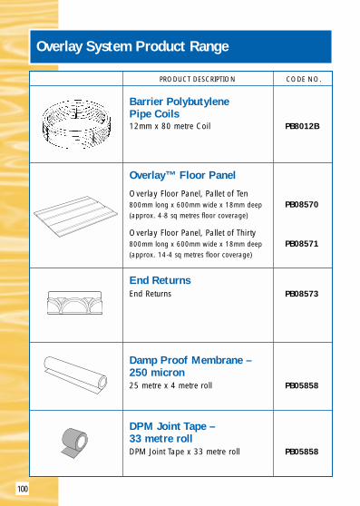
100
PRODUCT DESCRIPTION CODE NO.
Barrier PolybutylenePipe Coils12mm x 80 metre Coil PB8012B
Overlay™ Floor Panel
Overlay Floor Panel, Pallet of Ten800mm long x 600mm wide x 18mm deep PB08570(approx. 4·8 sq metres floor coverage)
Overlay Floor Panel, Pallet of Thirty800mm long x 600mm wide x 18mm deep PB08571(approx. 14·4 sq metres floor coverage)
End ReturnsEnd Returns PB08573
Damp Proof Membrane – 250 micron25 metre x 4 metre roll PB05858
DPM Joint Tape – 33 metre rollDPM Joint Tape x 33 metre roll PB05858
Overlay System Product Range

101
PRODUCT DESCRIPTION CODE NO.
Foam Spacer Strip –20 metre rollFoam Spacer Strip x 20 metre roll PB05856
Self Adhesive Pipe ClipsSelf Adhesive Pipe Clips x 50 pack PB02912
Polyurethane ExpandingFoam GluePolyurethane Expanding Foam Glue PB776
Jointing StaplesJointing Staples x box of 1000 PB02913(approximately 70 square metresusage)
Adaptor Setincluding 12mm Pipe Stiffeners PB18151215mm x 12mm Adaptor includingPipe Stiffeners
Overlay System Product Range
Bend overtab to
secure pipe

102
PRODUCT DESCRIPTION CODE NO.
15mm Manifold15mm Manifold - 2 Port PB1273715mm Manifold - 3 Port PB1273815mm Manifold - 4 Port PB1273915mm Manifold - 5 Port PB1274015mm Manifold - 6 Port PB1274115mm Manifold - 7 Port PB1274215mm Manifold - 8 Port PB1274315mm Manifold - 9 Port PB1274415mm Manifold - 10 Port PB1274515mm Manifold - 11 Port PB1274615mm Manifold - 12 Port PB12747
UFCH Valve ActuatorsValve Actuator (2 wire) PB00401Valve Actuator (4 wire) PB00402
Isolation Valves (1 inch)(1 Pair)Isolation Valves - use to connect PB01732manifolds to both UFCH Control Packand Modulating Unit
Wiring CentreFor use with two wire adaptors PB23010
Overlay System Product Range
Push-Fit Ends
(C/W Mounting Brackets,Drain Cock & Air Bleed)
Push-Fit Ends
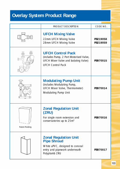
103
PRODUCT DESCRIPTION CODE NO.
UFCH Mixing Valve22mm UFCH Mixing Valve PB21905828mm UFCH Mixing Valve PB219059
UFCH Control Pack(includes Pump, 2 Port Motorised Valve,UFCH Mixer Valve and Isolating Valve) PB970015UFCH Control Pack
Modulating Pump Unit(includes Modulating Pump, UFCH Mixer Valve, Thermometer) PB970014Modulating Pump Unit
Zonal Regulation Unit(ZRU)For single room extension and PB970016conservatories up to 25m2
Zonal Regulation UnitPipe ShroudWhite uPVC, designed to concealentry and pipework underneath PB970017Polyplumb ZRU
Overlay System Product Range
Patent Pending

POLYFAST ADAPTORS
104
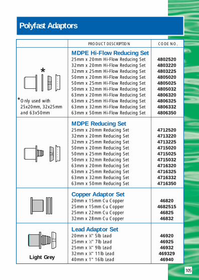
105
PRODUCT DESCRIPTION CODE NO.
MDPE Hi-Flow Reducing Set25mm x 20mm Hi-Flow Reducing Set 480252032mm x 20mm Hi-Flow Reducing Set 480322032mm x 25mm Hi-Flow Reducing Set 480322550mm x 20mm Hi-Flow Reducing Set 480502050mm x 25mm Hi-Flow Reducing Set 480502550mm x 32mm Hi-Flow Reducing Set 480503263mm x 20mm Hi-Flow Reducing Set 480632063mm x 25mm Hi-Flow Reducing Set 480632563mm x 32mm Hi-Flow Reducing Set 480633263mm x 50mm Hi-Flow Reducing Set 4806350
MDPE Reducing Set25mm x 20mm Reducing Set 471252032mm x 20mm Reducing Set 471322032mm x 25mm Reducing Set 471322550mm x 20mm Reducing Set 471502050mm x 25mm Reducing Set 471502550mm x 32mm Reducing Set 471503263mm x 20mm Reducing Set 471632063mm x 25mm Reducing Set 471632563mm x 32mm Reducing Set 471633263mm x 50mm Reducing Set 4716350
Copper Adaptor Set20mm x 15mm Cu Copper 4682025mm x 15mm Cu Copper 468251525mm x 22mm Cu Copper 4682532mm x 28mm Cu Copper 46832
Lead Adaptor Set20mm x 3⁄8” 5lb Lead 4692025mm x 1⁄2” 7lb Lead 4692525mm x 3⁄4” 9lb Lead 4693232mm x 3⁄4” 11lb Lead 46932940mm x 1” 16lb Lead 46940
Polyfast Adaptors
Light Grey
*
*Only used with25x20mm, 32x25mmand 63x50mm

106
PRODUCT DESCRIPTION CODE NO.
Polyethylene Adaptor Set20mm x 3⁄8” Polyethylene 467NG12(Red)20mm x 1⁄2” Polyethylene 465C1225mm x 3⁄4” Polyethylene 465C3432mm x 1” Polyethylene 465C150mm x 11⁄4” Polyethylene 465C11450mm x 11⁄2” Polyethylene 465C11263mm x 2” Polyethylene 465C2
Polyethylene Adaptor Set25mm x 1⁄2” Polyethylene 465D1225mm x 3⁄4” Polyethylene 465D3432mm x 1” Polyethylene 465D150mm x 11⁄4” Polyethylene 465D1450mm x 11⁄2” Polyethylene 465D112
Polyethylene Adaptor Set20mm x 1⁄2” Polyethylene 466C1225mm x 3⁄4” Polyethylene 466C3432mm x 1” Polyethylene 466C150mm x 11⁄4” Polyethylene 466C11450mm x 11⁄2” Polyethylene 466C11263mm x 2” Polyethylene 466C2
Polyethylene Adaptor Set20mm x 1⁄2” Polyethylene 466D1220mm x 3⁄8” Polyethylene 466D3825mm x 3⁄4” Polyethylene 466D3432mm x 1” Polyethylene 466D150mm x 11⁄4” Polyethylene 466D1450mm x 11⁄2” Polyethylene 466D1263mm x 2” Polyethylene 466D2
Polyfast Adaptors
Mid Blue
Light Green
Dark Blue
Dark Green
Low DensityBS1972:
1967 Class CTo connect3/8” use
1/2” 467NG12with 20mm
Nut and Body
Low DensityBS1972:
1967 Class D
High DensityBS3284:
1967 Class C
High Density
BS3284:1967
Class D

107
PRODUCT DESCRIPTION CODE NO.
Polyethylene Adaptor Set20mm x 1⁄2” Polyethylene 467NG1225mm x 3⁄4” Polyethylene 467NG3432mm x 1” Polyethylene 467NG150mm x 11⁄4” Polyethylene 467NG11450mm x 11⁄2” Polyethylene 467NG11263mm x 2” Polyethylene 467NG2
Polyethylene Adaptor Set20mm x 1⁄2” Polyethylene 467HG1225mm x 3⁄4” Polyethylene 467HG3432mm x 1” Polyethylene 467HG150mm x 11⁄4” Polyethylene 467HG11450mm x 11⁄2” Polyethylene 467HG112
PVC/Galvanised Steel Adaptor20mm x 3⁄8” PVC/Galv. Steel 472203825mm x 1⁄2” PVC/Galv. Steel 472251232mm x 3⁄4” PVC/Galv. Steel 472323440mm x 1” PVC/Galv. Steel 47240
Swivel Adaptor20mm x 1⁄2” BSP 4752025mm x 1⁄2” BSP 475251225mm x 3⁄4” BSP 4752525mm x 1” BSP 47525132mm x 1” BSP 4753232mm x 11⁄4” BSP 47532114
Push-fit and PolyfastAdaptor Couplings20mm Push-fit/Polyfast Adaptor Coupling 4052025mm Push-fit/Polyfast Adaptor Coupling 4052532mm Push-fit/Polyfast Adaptor Coupling 4053250mm Push-fit/Polyfast Adaptor Coupling 4055063mm Push-fit/Polyfast Adaptor Coupling 40563
Polyfast Adaptors
Red
Light Blue
NB: Not endload bearing.Must beanchored orclamped toprevent pullout.
Complete with seal
Enables Polyfast adaptorsto be used
Low DensityBS1972:
1961NormalGauge
IS134:1977
Low DensityBS1972:
1961 HeavyGauge
IS134:1977
PVCBS3505/6Galv. Steel BS1387
To adaptPolyfast or
Push-fitSocket to
Female BSPSwivel
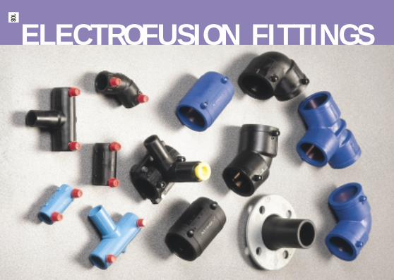
ELECTROFUSION FITTINGS
108

109
Electrofusion 20mm to 63mm OD
Blue and Black, 12 Bar rated to the requirements ofWRC. WIS 4-32-14.20mm to 63mm MDPE to BS6572 and BS6730.
IntroductionEach fitting is marked with the fusion time and cooling time.Available in Blue or Black, please specify when ordering.A simple to follow fusion system.
Socket fittings are used which consist of an injection mouldedPolyethylene body with an integral heating element and 2terminals.Fusion occurs when fittings are energised by means of a 39·5Volt electrofusion control box connected to a suitable 110 Volt4KVA generator.
Jointing InstructionsCut pipe ends square and deburr. Clearly mark depth of entry onpipe. Scrape OD of pipe to remove surface layer. Ensure pipesand fitting are completely clean and dry. Insert pipes into fittingup to pipe stop. Connect control unit leadsto fitting terminals. Switch on control unit.Enter and observe the correct fusion andcooling time detailed on each fitting. Do notmove fitting assembly until the fusion timeand cooling period are complete.
ClampsMinimise the risk of accidental movementand assist in correct pipe alignment. Specialsaddle clamps are needed for tapping teesto provide a constant load between fittingand pipe during the fusion cycle.

110
PRODUCT DESCRIPTION CODE NO.
Electrofusion Coupler20mm Coupler EF20C25mm Coupler EF25C32mm Coupler EF32C50mm Coupler EF50C63mm Coupler EF63C
Electrofusion Reducer25mm x 20mm Reducer EF25R32mm x 20mm Reducer EF322OR32mm x 25mm Reducer EF32R63mm x 50mm Reducer EF63R
Electrofusion Tee25mm Tee EF25T32mm Tee EF32T50mm Tee EF50T63mm Tee EF63T
Electrofusion Tapping Tee50mm x 32mm Tapping Tee EF5032S63mm x 32mm Tapping Tee EF6332S
Electrofusion 90° Elbow20mm 90° Elbow EF209025mm 90° Elbow EF259032mm 90° Elbow EF329050mm 90° Elbow EF509063mm 90° Elbow EF6390
Electrofusion 45° Elbow25mm 45° Elbow EF254532mm 45° Elbow EF324550mm 45° Elbow EF504563mm 45° Elbow EF6345
Electrofusion Fittings 20mm to 63mm OD

111
PRODUCT DESCRIPTION CODE NO.
Spigot Fittings for use in Electrofusion Sockets
Spigot Reducer50mm x 20mm Spigot Reducer 308502050mm x 25mm Spigot Reducer 308502550mm x 32mm Spigot Reducer 308503263mm x 20mm Spigot Reducer 308632063mm x 25mm Spigot Reducer 308632563mm x 32mm Spigot Reducer 308633263mm x 50mm Spigot Reducer 3086350
Spigot Fittings for use in Electrofusion Sockets
Spigot Stop End20mm Spigot Stop End 3092025mm Spigot Stop End 3092532mm Spigot Stop End 3093250mm Spigot Stop End 3095063mm Spigot Stop End 30963
Spigot Fittings for use in Electrofusion Sockets
Spigot Flange Assembly63mm Stub LS63ST63mm Backing Ring 63NP1663mm Gasket 50GASK
Replacement Grab Rings20mm Replacement Grab Rings 3922025mm Replacement Grab Rings 3922532mm Replacement Grab Rings 3923250mm Replacement Grab Rings 3925063mm Replacement Grab Rings 39263
Electrofusion Fittings 20mm to 63mm OD

112
Notes

113
Notes

114
Notes

115
Notes

POLYPIPEBUILDING
PRODUCTS LTD
Broomhouse Lane, Edlington, Doncaster DN12 1ESTelephone: (01709) 770000 Fax: (01709) 770001
2410 London Road, Mount Vernon, Glasgow G32 8XZTelephone: (0141) 778 8822 Fax: (0141) 778 2703
Dromore Road, Lurgan, Craigavon, Co. Armagh,Northern Ireland BT66 7HLTelephone: (0283) 888 1270 Fax: (0283) 888 2344
POLYPIPEGROUP
COLD WATERSUPPLY SYSTEMS
incorporating Compression, Push-fit and Electrofusion Fittings
HOT & COLD PLUMBING& HEATING SYSTEM
UNDERFLOOR CENTRALHEATING SYSTEM
www.polyplumb.co.uk
www.ufch.com
www.polypipe.com/bp