han q le© ece 3336 introduction to circuits & electronics lecture set #10 signal analysis &...
TRANSCRIPT
Han Q Le©
ECE 3336 Introduction to Circuits & Electronics
Lecture Set #10Signal Analysis & Processing –Frequency Response & Filters
Dr. Han LeECE Dept.

Han Q Le©
Outline• Review• Signal analysis
– Power spectral density• Frequency response of a system (circuit)
– Transfer function– Bode plot
• Filters– Analog– Digital
Han Q Le©
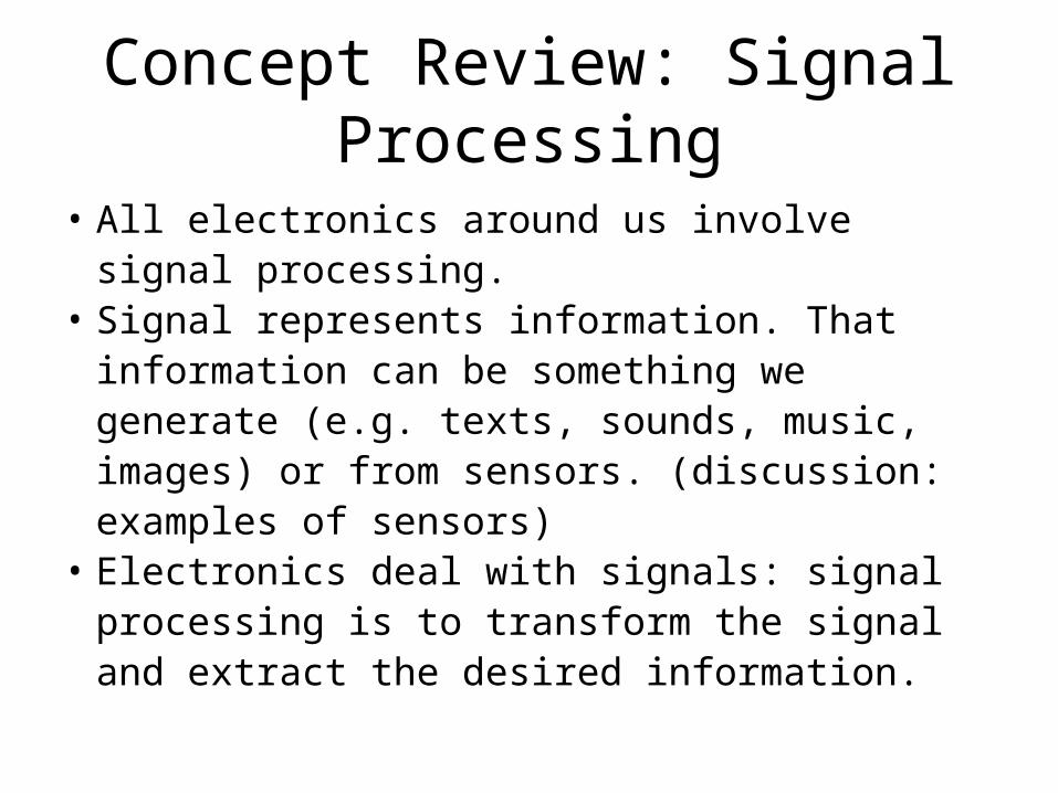
Concept Review: Signal Processing
• All electronics around us involve signal processing.
• Signal represents information. That information can be something we generate (e.g. texts, sounds, music, images) or from sensors. (discussion: examples of sensors)
• Electronics deal with signals: signal processing is to transform the signal and extract the desired information.

Han Q Le©
Concept Review: Signal Processing (cont.)• Signal processing is a general concept, not a single
specific thing. It includes:– signal synthesis or signal acquisition– signal conditioning (transforming): shaping, filtering,
amplifying– signal transmitting– signal receiving and analysis: transforming the signal,
converting into information
• Signal processing is mathematical operation; electronics are simply tools.
• Computation is high-level signal processing: dealing directly with information rather than signal.

Han Q Le©
Applications of mathematical techniques
Fourier transform
Harmonic function
Complex number
&analysisPhasors
Signal and AC circuit problems• RLC or any time-varying linear
circuits. Applicable to linear portion of circuits that include nonlinear elements
• Signal processing• signal analysis (spectral
decomposition)• filtering, conditioning (inc
amplification)• synthesizing
Note: The main lecture material is in the Mathematica file – this is only for concept summary

Han Q Le©
Homework (to be seen in HW 8)
Choose an electronic system around you (e. g. a TV, DVD player, phone,…); show a functional block diagram and describe the signal processing sequence (end to end).
Han Q Le©
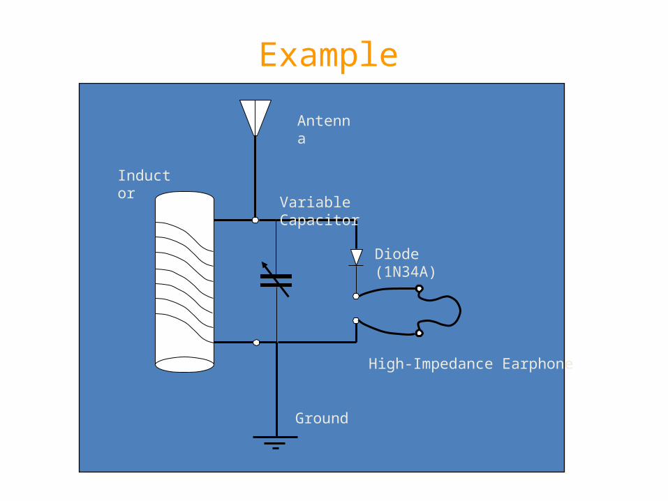
Example
Antenna
Ground
Inductor
Variable Capacitor
Diode (1N34A)
High-Impedance Earphone
Han Q Le©
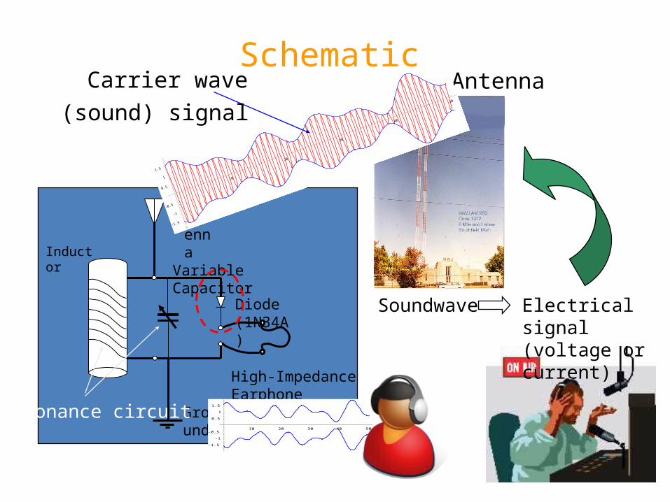
Schematic
Antenna
Ground
Inductor
Variable Capacitor
Diode (1N34A)
High-Impedance Earphone
Soundwave Electrical signal (voltage or current)
Antenna
10
20
30
40
50
-1.5
-1
-0.5
0.5
1
1.5
Carrier wave(sound) signal
Resonance circuit10 20 30 40 50
-1.5
-1
-0.5
0.5
1
1.5

Han Q Le©
Link to Mathematica file: AM FM

Han Q Le©
Outline• Review• Signal analysis
– Power spectral density• Frequency response of a system (circuit)
– Transfer function– Bode plot
• Filters– Analog– Digital

Han Q Le©
Signal Fourier (or harmonic) Analysis
• Treat each time-finite signal as if it is composed of many harmonics, using Fourier series
xt a 0 n 1 a n C osn t n 1
b n Sinn t In complex (or Euler) representation, Fourier
series coefficients Xm are phasor components,
xt m X m m t
X m X m m

Han Q Le©
Signal Fourier (or harmonic) Analysis (cont)
• If the signal is real (all cases involving real physical quantity), then:
Hence, we need to keep only positive frequencies A signal can be represented by a plot of | Xm | vs. frequency,
or usually | Xm |2 if x(t) is voltage or current, known as the signal magnitude spectrum, or its power spectral density.
Equally important is the phase spectrum: plot of fm vs. frequency
X m X m m
X m X m
X m X m m
Han Q Le©
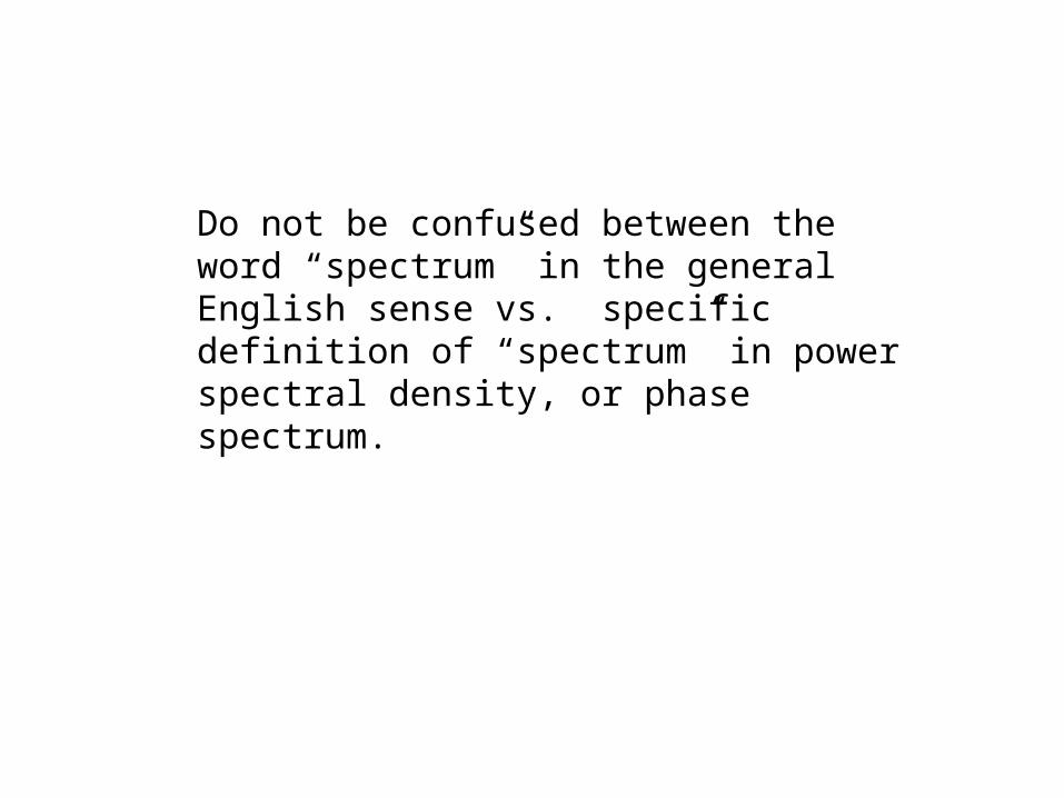
Do not be confused between the word “spectrum” in the general English sense vs. specific definition of “spectrum” in power spectral density, or phase spectrum.

Han Q Le©
The Electromagnetic Spectrum
Visible
UV & solar blind

Han Q Le©
Example of Spectra
0 1000 2000 3000 4000 5000 140
120
100
80
60
0 1000 2000 3000 4000 5000 3
2
1
0
1
2
3
0.89 s 11 025 H z

Han Q Le©
Example of Spectra
0 1000 2000 3000 4000 5000
120
100
80
60
0.79 s 11 025 H z
0 1000 2000 3000 4000 5000 3
2
1
0
1
2
3

Han Q Le©
Outline• Review• Signal analysis
– Power spectral density• Frequency response of a circuit
– Transfer function– Bode plot
• Filters– Analog– Digital
Han Q Le©
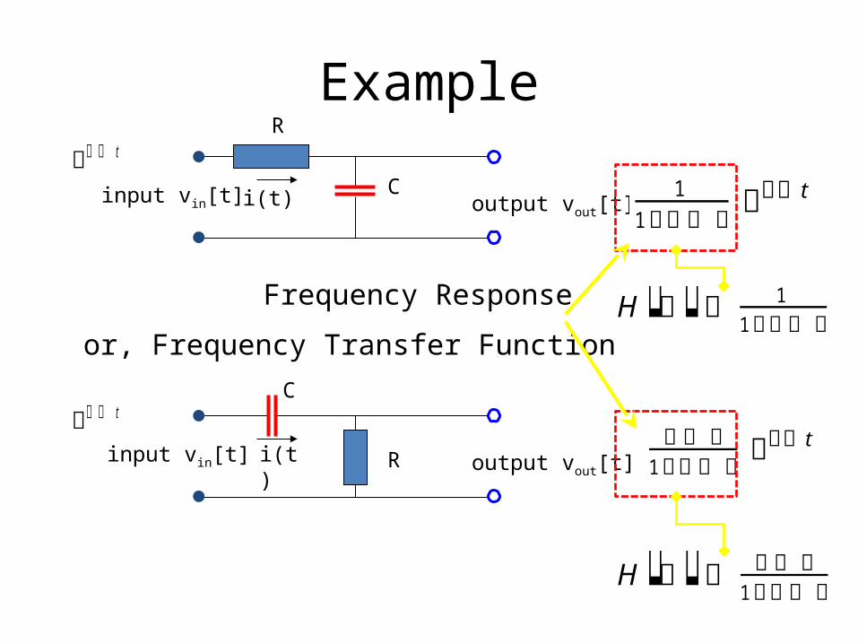
Example
R
C
output vout[t]i(t)input vin[t]
t
R
Cinput vin[t] output vout[t]i(t)
t 1
1 t
1
t
Frequency Response
or, Frequency Transfer FunctionH 1
1
H 1
Han Q Le©
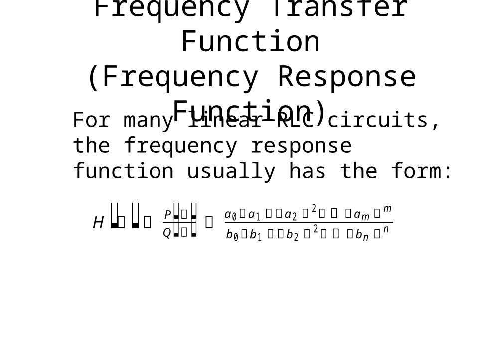
Frequency Transfer Function(Frequency Response Function)
H P Q a 0 a 1 a 2 2 a m m
b 0 b 1 b 2 2 b n n
For many linear RLC circuits, the frequency response function usually has the form:
Han Q Le©
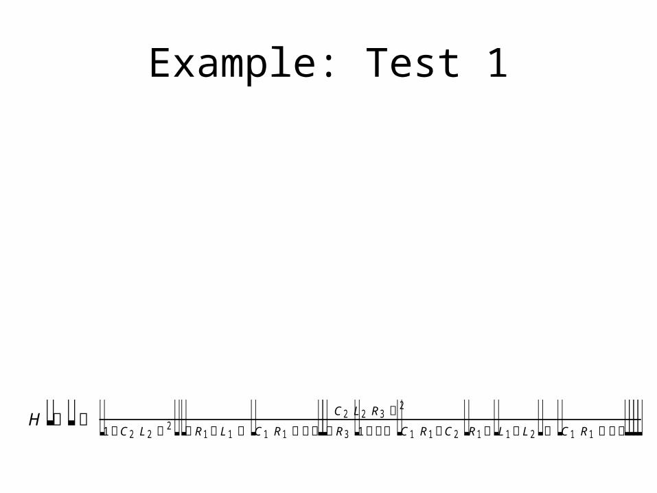
Example: Test 1
H C 2 L 2 R 3 21 C 2 L 2 2 R 1 L 1 C 1 R 1 R 3 1 C 1 R 1 C 2 R 1 L 1 L 2 C 1 R 1

Han Q Le©
Bode Plot for Vout in Test 1
1000 104 105 106 3
2
1
0
1
2
3
F requency HzPh
ase
Shif
trad1000 104 105 106
10 4
0.001
0.01
0.1
1
F requency Hz
Am
plit
udeR
espo
nse

Han Q Le©
Applications of Frequency Transfer Function
• Any signal can be decomposed as a sum of many phasors (Fourier components)
• For a linear system, each component can be multiplied by H[w] to obtain the output phasor
• The signal output is simply the sum of all the individual phasor (Fourier component) outputs.

Han Q Le©
Example
0.00.51.0 1.52.02.5 3.00.60.40.20.00.20.40.6
0.00.51.0 1.52.02.5 3.0
0.40.20.00.20.4
0.0 0.5 1.0 1.5 2.0 2.5 3.02
0
2
4
6
8
0.0 0.5 1.0 1.5 2.0 2.5 3.0
0
2
4
6
8
R
Cinput vin[t] output vout[t]i(t)
Han Q Le©
Outline• Review• Signal analysis
– Power spectral density• Frequency response of a circuit
– Transfer function– Bode plot
• Filters– Analog– Digital

Han Q Le©
General Filter Concept Review
0 1000 2000 3000 4000 5000
140
120
100
80
60
Frequency H zPow
erS
pect
ralD
ensi
tyThis is a filter This is also filter This is another filter

Han Q Le©
General Filter Concept• A system (electronic circuit) can be
designed such that its transfer function H[w] has preference (let through) certain ranges of frequencies while attenuating (blocking) other frequencies
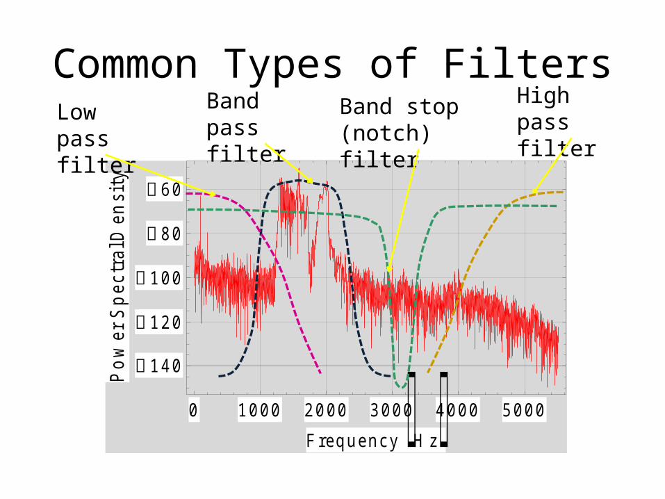
• Such a circuit is called a filter. Filter is a concept about the function of a circuit, not the circuit itself.
• Filter includes both amplitude response and phase shift. Usually, only amplitude is plotted.
Han Q Le©
Common Types of Filters
0 1000 2000 3000 4000 5000
140
120
100
80
60
Frequency H zPow
erS
pect
ralD
ensi
tyLow pass filter
Band pass filter
High pass filter
Band stop (notch) filter

Han Q Le©
Design of Filters• A circuit designed to perform filtering
function on an analog signal is called an analog filter.
• If a signal is digital (converted into a sequence of number), a filter can be realized as a mathematical operation, this is called digital filter.
• Digital filter can be done with any computing device: from a DSP chip to a computer.

Han Q Le©
Example of Simple Analog Filters RC band stop filter.
RC bandpass filters

Han Q Le©
Example of Simple Analog FiltersRLC resonant filter

Han Q Le©
Example of Simple Analog FiltersNotch filter application: rejection line 60-Hz signal
Han Q Le©
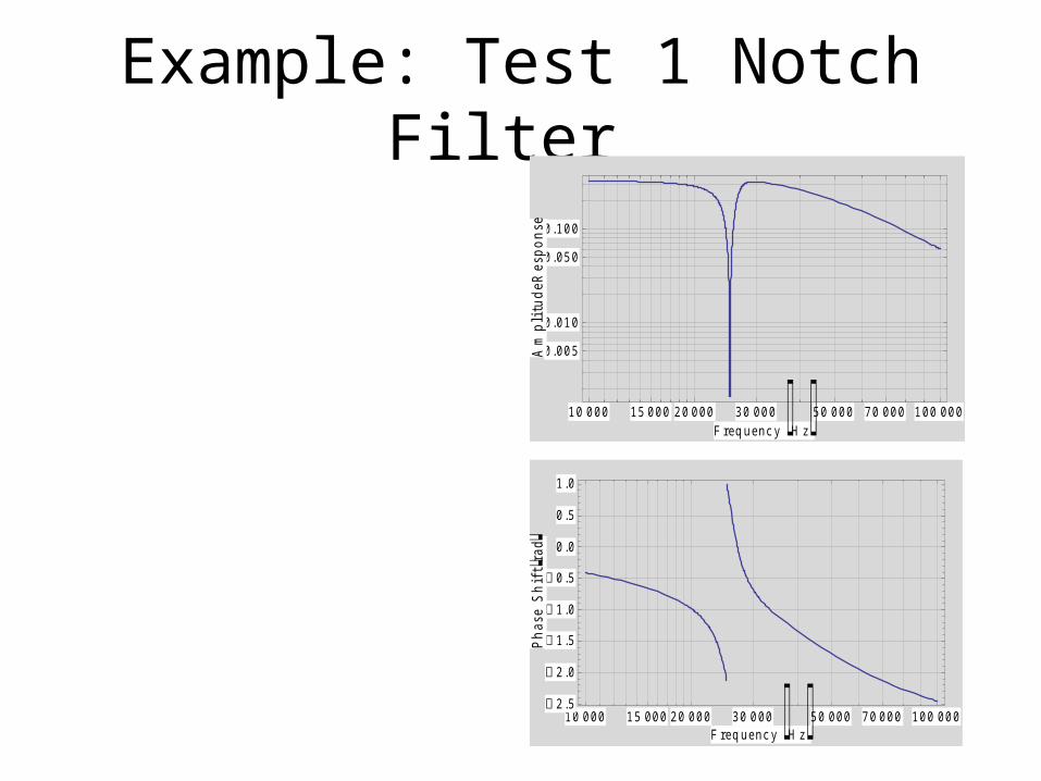
Example: Test 1 Notch Filter
10 000 100 00050 00020 000 30 00015 000 70 000
0.005
0.010
0.050
0.100
F requency HzA
mpl
itud
eRes
pons
e
10 000 100 00050 00020 000 30 00015 000 70 000 2.5
2.0
1.5
1.0
0.5
0.0
0.5
1.0
F requency Hz
Phas
eSh
iftrad
Han Q Le©
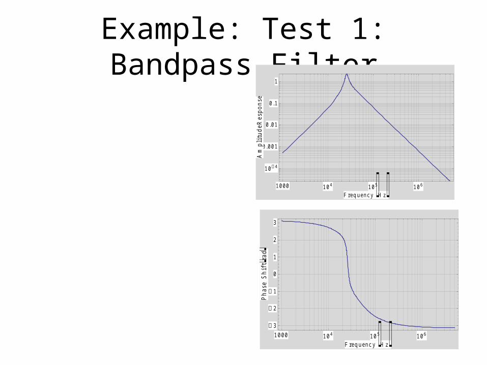
Example: Test 1: Bandpass Filter
1000 104 105 106 3
2
1
0
1
2
3
F requency Hz
Phas
eSh
iftrad
1000 104 105 106
10 4
0.001
0.01
0.1
1
F requency Hz
Am
plit
udeR
espo
nse

Han Q Le©
Digital Filter• Any filter function can be achieved with digital filter
Micro-processor(DSP)
Signal input
User input
Filtered signal output

Han Q Le©
Digital Filter
This is a filterThis is another filter This is another type
of filterThis is a filterThis is another filter This is another type
of filter
• Digital filter can also be designed with sharp cut-off edge that is difficult with analog filter.

Han Q Le©
http://www2.renesas.com/linear/en/application/equipment/cd.html

Han Q Le©From TI http://focus.ti.com/docs/solution/folders/print/530.html