half-wave parabolic reflector antenna...
TRANSCRIPT
HALF-WAVE PARABOLIC
REFLECTOR ANTENNA
OPTIMIZATION
Parker Singletary, Carson Smith
Advisor: Dr. Gregory J. Mazzaro
Department of Electrical & Computer Engineering
The Citadel, The Military College of South Carolina
171 Moultrie St., Charleston, SC 29409 September 2015
PROJECT GOALS Design, in simulation, a UHF antenna producing maximum power-
on-target, directly in front of the antenna, at a given distance
Minimal power reflection into feeder line
Optimize antenna parameters by using FEKO, a method-of-
moments-based electromagnetic field solver, to vary its physical
dimensions
2
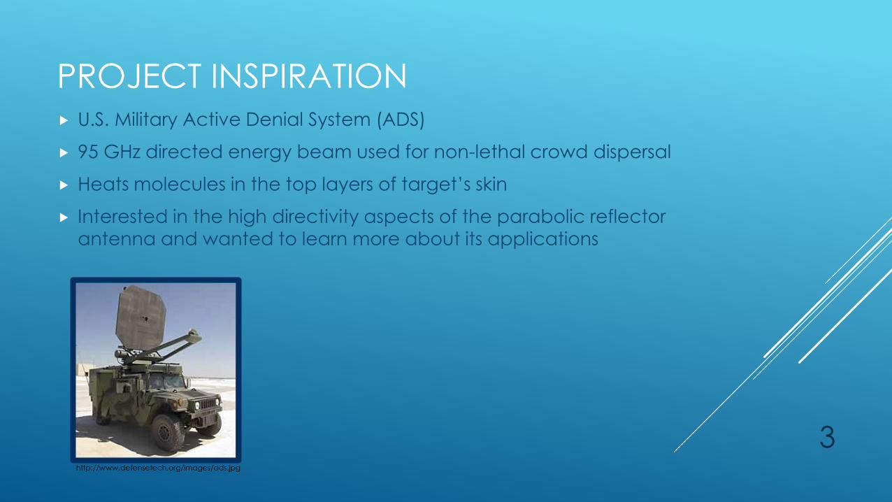
PROJECT INSPIRATION U.S. Military Active Denial System (ADS)
95 GHz directed energy beam used for non-lethal crowd dispersal
Heats molecules in the top layers of target’s skin
Interested in the high directivity aspects of the parabolic reflector antenna and wanted to learn more about its applications
3 http://www.defensetech.org/images/ads.jpg
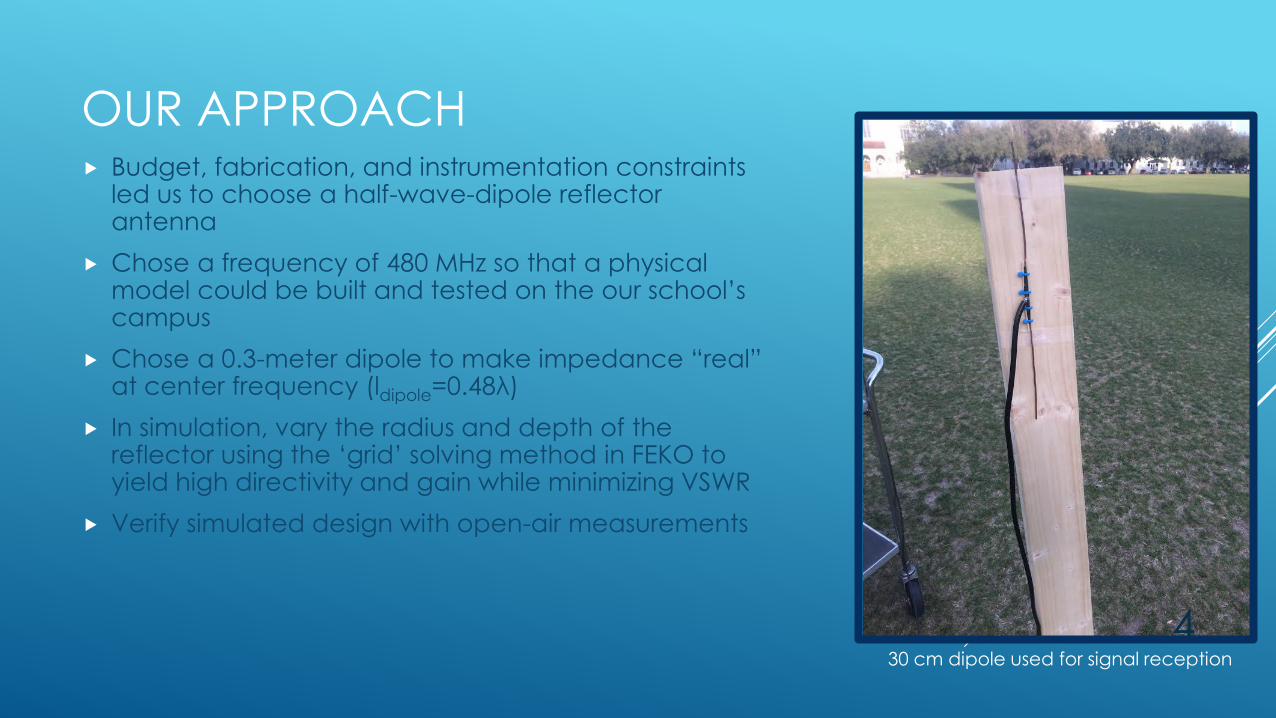
OUR APPROACH Budget, fabrication, and instrumentation constraints
led us to choose a half-wave-dipole reflector antenna
Chose a frequency of 480 MHz so that a physical model could be built and tested on the our school’s campus
Chose a 0.3-meter dipole to make impedance “real” at center frequency (ldipole=0.48λ)
In simulation, vary the radius and depth of the reflector using the ‘grid’ solving method in FEKO to yield high directivity and gain while minimizing VSWR
Verify simulated design with open-air measurements
30 cm dipole used for signal reception
4
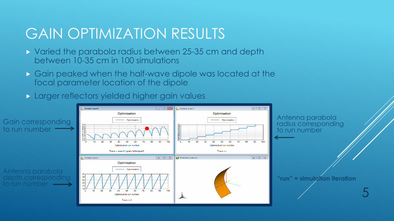
GAIN OPTIMIZATION RESULTS Varied the parabola radius between 25-35 cm and depth
between 10-35 cm in 100 simulations
Gain peaked when the half-wave dipole was located at the focal parameter location of the dipole
Larger reflectors yielded higher gain values
5
Antenna parabola radius corresponding to run number
Antenna parabola depth corresponding to run number
Gain corresponding to run number
“run” = simulation iteration
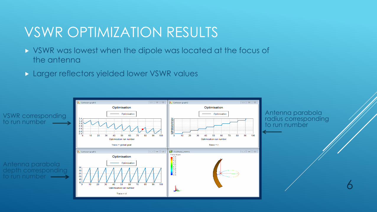
VSWR OPTIMIZATION RESULTS VSWR was lowest when the dipole was located at the focus of
the antenna
Larger reflectors yielded lower VSWR values
6
Antenna parabola radius corresponding to run number
Antenna parabola depth corresponding to run number
VSWR corresponding to run number

SELECTED MODEL Although simulation run 95 yielded the most optimal results, we
selected run 75, so the implemented antenna would not be too
large to handle during testing
In size range, chose model with high gain (8 dB) and reasonable
VSWR (2.5)
Determined parabola’s equation for fabrication
Depth = 23 cm
Radius = 33 cm
Y=0.02112029x2
7
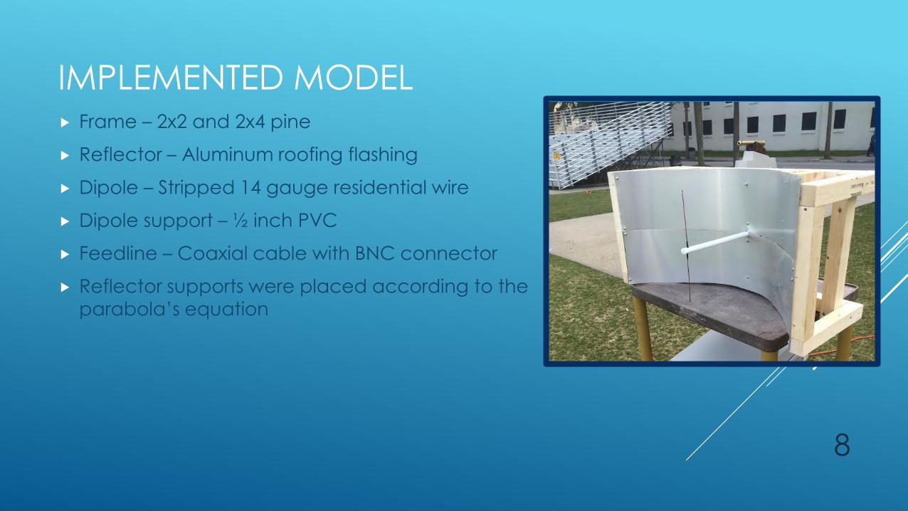
IMPLEMENTED MODEL Frame – 2x2 and 2x4 pine
Reflector – Aluminum roofing flashing
Dipole – Stripped 14 gauge residential wire
Dipole support – ½ inch PVC
Feedline – Coaxial cable with BNC connector
Reflector supports were placed according to the
parabola’s equation
8

RADIATION PATTERN AND BEAMWIDTH TEST Connected implemented antenna to
function generator producing a 1 mW constant sinusoid at 480 MHz
Utilized second dipole as a receiver connected to a spectrum analyzer for measurements
Placed second dipole at a distance of 50 feet from transmitting antenna (~20λ) and measured the average power received along a 180° swath at 5° intervals
Determined that the antenna has a 40° 3-dB beamwidth
-58
-56
-54
-52
-50
-48
-46
-44
-42
-40
0 10 20 30 40 50 60 70 80 90 100 110 120 130 140 150 160 170 180
Po
we
r R
ec
eiv
ed
(d
Bm
)
Azimuth (degrees)
Received Power vs. Angle
Received Power vs. Angle 3 dB down
9
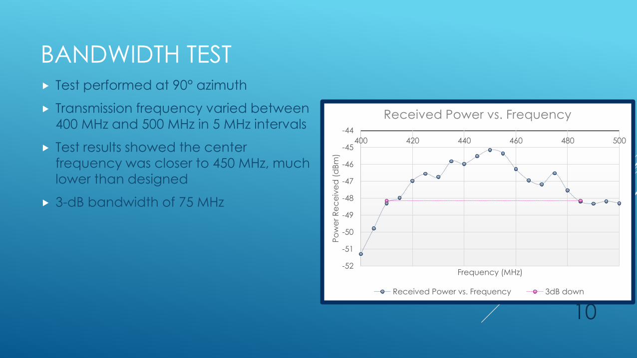
BANDWIDTH TEST Test performed at 90° azimuth
Transmission frequency varied between
400 MHz and 500 MHz in 5 MHz intervals
Test results showed the center frequency was closer to 450 MHz, much
lower than designed
3-dB bandwidth of 75 MHz
-52
-51
-50
-49
-48
-47
-46
-45
-44
400 420 440 460 480 500
Po
we
r R
ec
eiv
ed
(d
Bm
)
Frequency (MHz)
Received Power vs. Frequency
Received Power vs. Frequency 3dB down
10

COMPARISON OF RESULTS Experimental gain pattern tracked
theoretical gain pattern within 1dBm
Performed curve fitting in Excel with a
4th-order polynomial to smooth
measured data, for a clearer
comparison against simulated results
Testing methods likely induced much of
the error (e.g. multipath, including ground bounce between Tx and Rx)
Tests were performed on a large field as
an anechoic chamber was unavailable
-2.00
-1.00
0.00
1.00
2.00
3.00
4.00
5.00
6.00
7.00
8.00
0 50 100 150
Ga
in (
dB
m)
Angle (Degrees)
Theoretical vs. Experimental Gain
Theoretical GainExperimental GainPoly. (Experimental Gain)
11
CONCLUSIONS We were able to successfully design, simulate, and
build an optimized half-wave dipole reflector antenna
Simulation results showed clear tradeoffs between VSWR and gain when manipulating reflector geometry
Larger parabola radii resulted in more desirable gain and VSWR while depth variation yielded more contrasting output parameters, so parabola depth drove the design
The antenna’s operating frequency enables it be used for a variety of applications at low RF power, potentially in a secure point-to-point RF link or an RF device jammer
12
ACKNOWLEDGEMENTS
Department of Electrical & Computer
Engineering at The Citadel
Dr. Gregory J. Mazzaro, Advisor
Altair, FEKO software provider
Applied EM, Inc. (Hampton, VA)
Dr. C. J. Reddy
Thomas G. Campbell, Sr. 13
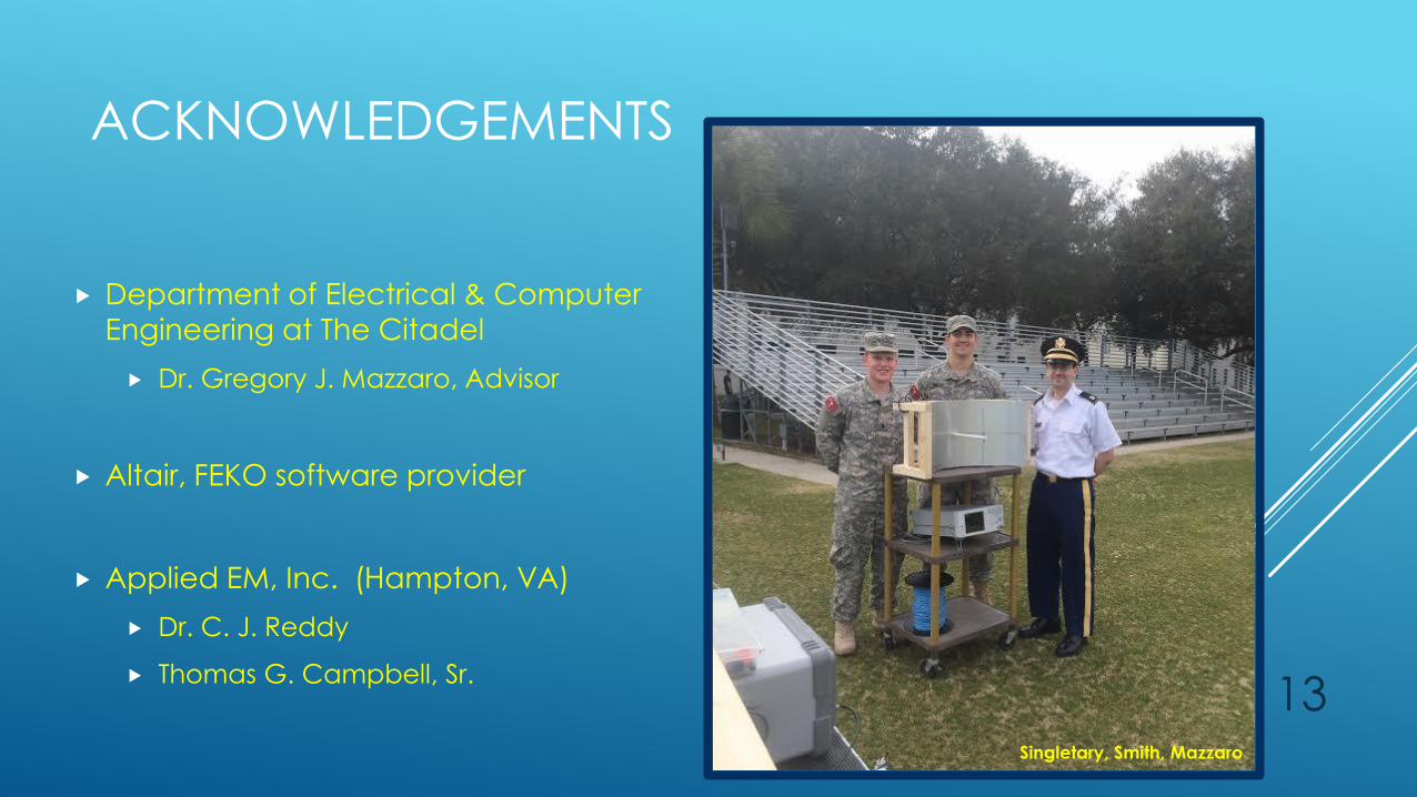
Singletary, Smith, Mazzaro