guidelines for service stations - nz transport agency · traffic engineering ... • policies and...
TRANSCRIPT

Guidelines forservice stations
RTS 13

Disclaimer
While this document is believed to be correct at the time of publication, the Land Transport SafetyAuthority and their employees or agents involved in its preparation and publication cannot acceptany liability for its contents or for any consequences arising from its use. People using thedocument should apply, and rely on, their own skill and judgement. They should not rely on itscontents in isolation from other sources of advice and information.
March 1996Reprinted June 1998, September 2001
Land Transport Safety AuthorityPO Box 2840WellingtonTelephone 04 494 8600Fascimile 04 494 8601
ISSN: 1170-5337ISBN: 0-478-20623-2

3
Preface 4
1. Introduction 5
2. Traffic engineering principles and crash data 6
3. Safety issues and recommended traffic management techniques in theurban speed environment 8
4. Safety issues and recommended traffic management techniques in therural speed environment 13
5. General safety considerations 15
6. Truckstops 20
References 21
Acknowledgements 22
Appendix 1: Australian literature 23
Appendix 2: Analysis of crash data 24
Appendix 3: Service station survey 27
Appendix 4: Driveway distance formula 37
Appendix 5: Crash types 38
Appendix 6: Visibility 39
Appendix 7: Glossary of terms 41
Contents

4
The safe design of service stations and driveways can prevent crashes and save lives. Over the fiveyear period from 1990-1994, 387 reported injury crashes at service stations resulted in four deaths,103 serious injuries and 364 minor injuries. There were also 876 reported non-injury crashes.
Historically the document Standard for service stations 1983, and its predecessors, were developedbecause the then Ministry of Transport was able to influence the siting of driveways and pumps atservice stations through the licensing process that existed.
In May 1988, the deregulation of the motor spirits industry enabled oil companies to own andoperate any number of service stations, as well as to set retail prices for the sale of fuel.
The continuance of this document was brought about by requests from local authorities, roadcontrolling authorities, engineers and planners. Many of the principles in this guideline have beenused throughout New Zealand and have obtained a wide acceptance at a working level by those inthe industry, as well as being embodied in many local authority district schemes and plans. Localauthorities who are preparing or reviewing their district plans under the Resource Management Act1991 may wish to refer to this guideline to evaluate and control any adverse effects that suchdevelopments could have on the natural and physical resources of New Zealand.
I would like to thank all those who contributed to the compilation of this document and commendto you the widespread use of this guideline.
Reg BarrettDirector, Land Transport Safety
Preface
5
Some characteristics of service stations changed considerably following the 1988 deregulation ofthe motor spirits industry.
The trend has been to develop large efficient operations on arterial routes and at intersections.
The more recent designs incorporate large forecourts, carwashes, drive-in banking facilities, andretail areas with convenience stores.
The result is that the modern service station is a significant attraction for motorists, cyclists andpedestrians.
The aim of this guideline is to provide a document that can help engineers and planners enhancethe road safety environment adjacent to the modern service station. The guideline also takes intoaccount the Resource Management Act 1991 and the changes that have occurred with servicestations over recent years.
Although this guideline has evolved from the former Standard for Service Stations 1983, many ofthe principles outlined in this document may also be appropriate for assessing the impacts of someother land uses, particularly those that exhibit moderate to high traffic generation.
This guideline has been formulated using the following:
• fundamental traffic engineering principles• Australian practice and guidelines• crash data• a survey of service stations at intersections• feedback on the draft guideline• the experience and opinions of a working group comprised of members from the traffic
engineering and town planning professions (see Acknowledgements).
1. Introduction

6
2. Traffic engineering principles and crash data
2.1 Fundamental traffic engineering principles
An understanding of fundamental traffic engineering principles is necessary to ensure safe roadingdesign. Some of the more important principles are:
• reducing the number of conflict points• separating the points of conflict• controlling vehicle speeds• defining vehicle paths.
The types of manoeuvres likely to occur at the driveway of a service station need to be known toensure safe design. The most common manoeuvres are merging, diverging and crossing. Weavingmanoeuvres may occur at some sites.
Every two-way driveway has nine conflict points (three merge, three diverge, three crossing),therefore midblock sites typically have 18 conflict points (two driveways) and intersection sitestypically have 27 conflict points (three driveways). The conversion of driveways to entry only orexit only reduces the number of conflict points from 18 to eight and 27 to 12 in midblock andintersection sites respectively.
By implementing traffic management techniques such as one-way driveways, solid islands andsolid medians, the number of conflict points can be reduced.
The conflict points associated with a service station driveway should be separated from theconflict points of an adjacent intersection.
This will separate the motorist’s decision points and better define vehicle paths at, and adjacent to,intersections.
2.1 Australian literature
A literature review undertaken by the working group researched the following topics:
• policies and guidelines for service stations• policies and guidelines for driveway locations.
The main points of interest regarding driveway location are summarised in Appendix 1.
2.3 Crash data and service station survey
The national reported service station injury crash data for the 1990-1994 five year period areanalysed in Appendix 2.
Table 2.1 summarises the injury crash data by urban/rural, intersection/midblock and manoeuvre.Right turn manoeuvres (in and out) comprise the majority of the data.
Manoeuvres classified as unknown are those that cannot be readily identified as left or right turn(in or out) without a full examination of the original traffic crash reports.

7
Table 2.1: Percentage of service station injury crashes by urban/rural, intersection/midblock andmanoeuvre (1990-1994)
Urban RuralManoeuvre Intersection Midblock Intersection MidblockLeft turn (in) 10 1 0 0Left turn (out) 5 6 6 0Right turn (in) 41 54 56 50Right turn (out) 24 33 20 25Unknown 20 6 18 25Total 100 100 100 100
A survey of 61 service stations located at intersections in urban speed environments (=< 70 km/h)was undertaken by the Land Transport Safety Authority (LTSA) (see Appendix 3 for an explanationand analysis of this survey).
The survey is limited because the database is not extensive (61 service stations, 28 crashes) and itwould have been impracticable to obtain traffic flows on driveways (exposure).
The results from this survey suggest that driveway proximity to an intersection is not a clearlyidentifiable problem.
2.4 Linking fundamental traffic engineering principles, Australian literature andcrash data
There has been criticism of the document Standard for service stations 1983 (1) regarding the issueof service stations at intersections; in particular the requirement that no driveway should be locatedwithin 30 metres of an intersection carrying more than 1,000 vph.
Results from the service station survey suggest that many crashes occur independently of thedistance from an intersection (a crash may be as likely to occur at 29 metres as at 31 metres).Therefore, the location of driveways at distances greater than 30 metres from intersections does notguarantee safety.
This guideline emphasises the use of traffic management techniques to address potential crashmanoeuvres, rather than imposing an arbitrary distance from intersections.
The user of this guideline requires sound engineering judgement to ensure that the most effectivecombination of traffic management techniques is used at each site under consideration. Theguideline recommends traffic management techniques to improve the negative road safety impacts.This approach is more aligned to the purpose and principles of the Resource Management Act.

8
3. Safety issues and recommended traffic managementtechniques in the urban speed environment
3.1 Summary of traffic management techniques
The main traffic management techniques used to increase safety at service stations are:
• solid medians• flush medians• increasing kerbside lane width• locating driveways clear of queues• traffic signs and markings• stopping restrictions
3.1.1 Solid mediansThe installation of a solid median may be the most effective technique for reducing crashes atboth intersection and midblock service station sites.
Median divided arterial roads can achieve a crash reduction of approximately 23 percent (Jackett[2]). Sound engineering judgement is required when assessing the benefits of using isolated sectionsof a solid median.
Solid medians prevent right turn manoeuvres which comprise at least 65 percent of intersectioncrash data and 87 percent of midblock crash data.
Intersection and midblock capacity are often improved as solid medians prevent right turning trafficfrom obstructing through traffic.
Solid medians should be designed to minimise the occurrence of hazardous manoeuvres, e.g. u-turns at the end of the median. This may require extending the median to a point where turns canbe safely accommodated. Consideration may need to be given to the consequences of restrictingaccess to other neighbouring properties.
The desirable minimum width of a solid median is 1.8 metres (to provide refuge for pedestrians),although in many situations a greater width will be required in order to enhance pedestrian safetyor accommodate traffic signals.
Refer to Guide to traffic engineering practice, Part 5 section 5.10.2 and Part 13 section 3.4.1 (3).
3.1.2 Flush mediansThe use of a flush median will improve some safety and operational issues, but is not aseffective as a solid median in addressing the major safety problem, i.e. right turn crashes.
Flush medians can achieve a midblock crash reduction of approximately 15 percent (Jackett [2]).
For exiting right turning vehicles, a flush median may assist the driver to select a suitable gap byeffectively breaking the manoeuvre into two parts.
A flush median addresses most rear end/right turn-in crashes, but right turn crashes resulting fromobscured visibility, e.g. visibility obscured by intersection queues or multi-lane traffic flows, are notfully addressed by a flush median.

9
The documents RTS 4 Guidelines for flush medians [4] and Manual of traffic signs and markings,Part II Markings [5] should be consulted for layout requirements.
3.1.3 Increasing kerbside lane width
Increasing the kerbside lane width can reduce left turn-in and left turn-out conflicts by providingmore space on the road for turning manoeuvres to take place. Safety is enhanced by ensuring thatthe relative speed between through traffic and turning traffic is low. This may be achieved bylowering speed and/or the angle of conflict.
In some situations, on-street parking will not be allowed so that the visibility requirements set outin section 5.1 can be achieved. In this case, the extra space on the road can be utilised to giveincreased kerbside lane width.
On urban state highways, the provision of appropriate acceleration and deceleration lanes may benecessary. The Transit New Zealand document Highway planning under the Resource ManagementAct 1991 [6] should be consulted.
3.1.4 Locating driveways clear of queued traffic
Right turn-in and right turn-out crashes are often attributed to obscured visibility, e.g. queuedtraffic at intersections. Some traffic management techniques applied in isolation, e.g. flush medians,cannot fully address right turn safety issues. However, the crash problem could be improved bycombining several techniques, such as installing a flush median and locating driveways clear ofqueued traffic on the approach leg.
In some situations, the installation of a flush median in conjunction with locating driveways clearof queued traffic will address right turn crashes. However, at sites where traffic queues extendbeyond the site boundary, the most effective technique is the installation of a solid median tophysically prevent right turns. Sound engineering judgement is required on a site by site basis.
3.2 Safety issues and recommended traffic management techniques
When assessing the road safety issues arising from entry and exit manoeuvres at service stations inthe urban speed environment, the practitioner should use table 3.2 to:
• highlight the major safety issues and problems associated with entry and exit manoeuvres• examine why the safety issues and problems exist• examine the effect that the safety issues and problems have on road safety and road operating
characteristics• identify the appropriate traffic management techniques to be used to improve the safety issues
and problems.
Sound engineering judgement will be needed to ensure that the traffic management techniquechosen is appropriate.

10
Table 3.2: Safety issues and recommended traffic management techniques for service stationsin urban speed environments
Manoeuvre Crash type % of crashesInter-section
Mid-block
Issues and problems Why problem exists Effect
Right turn-in 41 54 delay/safety • rear end crashes• delays motorists
entering station andthrough traffic
• reduced capacity onfrontage road
• deceleration• gap selection
obscured visibility/delay/safety
• right turn/right sidecrashes
• delay to motoristsentering station
• queued traffic• multi-lane flows• gap selection
Right turn-out 24 33 obscured visibility/delay/safety
• right turn/right sidecrashes
• delay to motoristsexiting station
• queued traffic• multi-lane flows• gap selection
• right turn/right sidecrashes
• delay to motoristsexiting station
Left turn-in 10 1 delay/safety • delay to throughtraffic
• rear end crashes• reduced road
capacity
• deceleration toenter driveway
Left turn-out 5 6 delay/safety • delay to throughtraffic
• left turn/left sidecrashes
• motorists exitingstation acceleratingto operating speed
• gap selection

11
Table 3.2 continued
Prominent causalfactors
Recommended traffic management technique (by road hierarchy)
Arterial Distributor Collector Local
• failure to signal• following too close• attention diverted
• solid median • solid median • flush median • centreline
• visibility limited byother traffic
• misjudged distance,size, position orspeed of traffic
• solid median• locate driveway
clear of queues
• solid median• locate driveway
clear of queues
• flush median• locate driveway
clear of queues
• centreline
• visibility limited byother traffic
• misjudged distance,size, position orspeed of traffic
• solid median• locate driveway
clear of queues
• solid median• locate driveway
clear of queues
• flush median• locate driveway
clear of queues
• centreline
• failure to signal• following too close• attention diverted
street parking
• widen kerbside lane• ban adjacent street
parking
• widen kerbside lane• ban adjacent street
parking
• widen kerbside lane • centreline
• misjudged distance,size, position orspeed of traffic
• failure to checkadequately
• widen kerbside lane• ban adjacent street
parking
• widen kerbside lane• ban adjacent street
parking
• widen kerbside lane • centreline
12
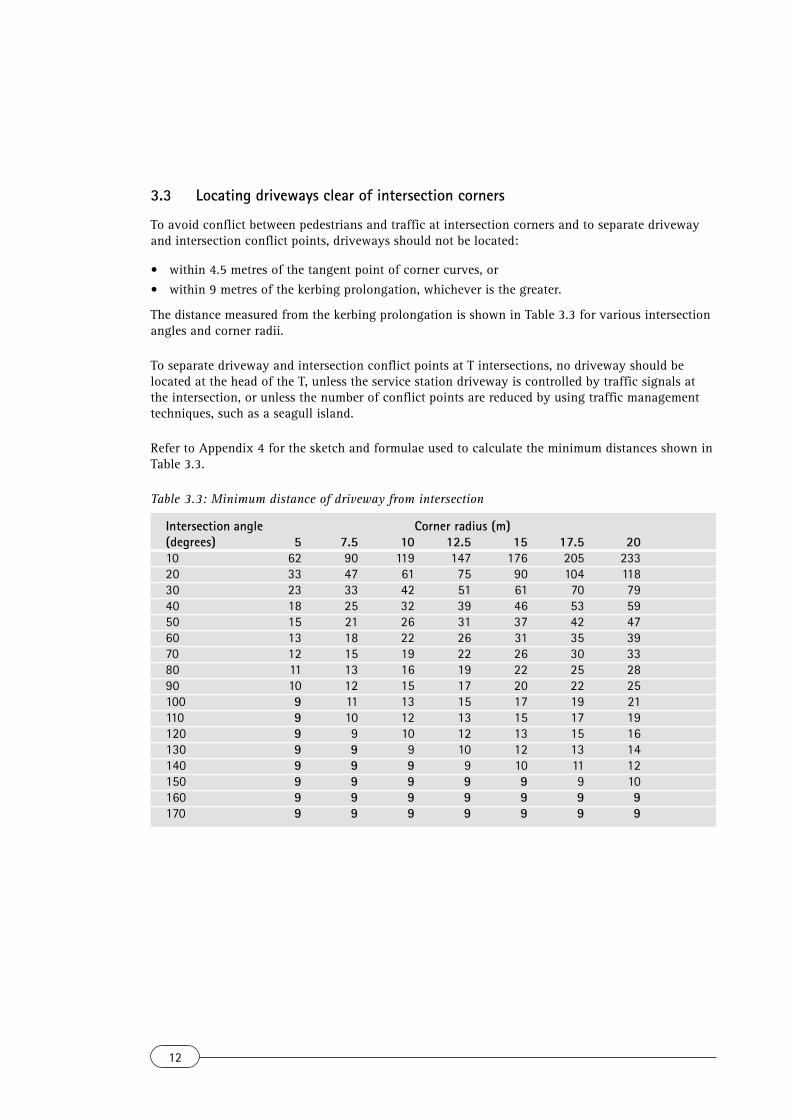
3.3 Locating driveways clear of intersection corners
To avoid conflict between pedestrians and traffic at intersection corners and to separate drivewayand intersection conflict points, driveways should not be located:
• within 4.5 metres of the tangent point of corner curves, or• within 9 metres of the kerbing prolongation, whichever is the greater.
The distance measured from the kerbing prolongation is shown in Table 3.3 for various intersectionangles and corner radii.
To separate driveway and intersection conflict points at T intersections, no driveway should belocated at the head of the T, unless the service station driveway is controlled by traffic signals atthe intersection, or unless the number of conflict points are reduced by using traffic managementtechniques, such as a seagull island.
Refer to Appendix 4 for the sketch and formulae used to calculate the minimum distances shown inTable 3.3.
Table 3.3: Minimum distance of driveway from intersection
Intersection angle Corner radius (m)(degrees) 5 7.5 10 12.5 15 17.5 2010 62 90 119 147 176 205 23320 33 47 61 75 90 104 11830 23 33 42 51 61 70 7940 18 25 32 39 46 53 5950 15 21 26 31 37 42 4760 13 18 22 26 31 35 3970 12 15 19 22 26 30 3380 11 13 16 19 22 25 2890 10 12 15 17 20 22 25100 9 11 13 15 17 19 21110 9 10 12 13 15 17 19120 9 9 10 12 13 15 16130 9 9 9 10 12 13 14140 9 9 9 9 10 11 12150 9 9 9 9 9 9 10160 9 9 9 9 9 9 9170 9 9 9 9 9 9 9
13
4. Safety issues and recommended traffic managementtechniques in the rural speed environment
4.1 Rural state highways
Crashes at service stations in the high speed environment (> 70 km/h) comprise 14 percent of thenational reported service station injury crash data.
In keeping with the nature of the business, most service stations in the high speed environment arelocated on state highways in order to serve reasonable traffic volumes. Of the 54 crashes in therural speed environment (Table 2.2, Appendix 2), 50 occurred on state highways and 4 on non-statehighway roads.
The requirements of the Transit New Zealand document Highway planning under the ResourceManagement Act 1991 [6] should be complied with for service stations situated on state highways.
4.2 Crash data
Right turn crashes are the major problem. The main points of interest are:
4.2.1 Midblock sites• small crash data set (four reported injury crashes)• right turn manoeuvres comprise 75 percent of the midblock crash data as follows:
(a) right turn-in/rear end (GC, GD, GE)* = 25%(b) right turn-in/left side (LB) = 25%(c) right turn-out/right side (JA) = 25%
* See Appendix 5 for crash types.
4.2.2 Intersection sites
Right turn manoeuvres comprise at least 75 percent of intersection crash data as follows:
• right turn-in/rear end (GC, GD, GE) = 30%• right turn-in/left side (LB) = 26%• right turn-out/right side (JA) = 14%• right turn-out/left side (KB) = 6%• left turn manoeuvres comprise 6 percent
of intersection crash data, i.e. left turn-out/right side (KA) = 6%
4.3 Traffic management techniques in the rural speed environment
4.3.1 Midblock sitesIt is essential to provide adequate lane width adjacent to service stations so that:
• vehicles entering and exiting can decelerate and accelerate without adversely affecting the freeflow of traffic on the frontage road
• through traffic can safely manoeuvre past vehicles entering or exiting the site.
The Transit New Zealand document Highway Planning under the Resource Management Act 1991[6] discusses the requirements for vehicle orientated commercial activities such as service stationssituated on state highways.

14
In order to achieve adequate lane width, localised road widening may be required adjacent toservice stations and truckstops situated on rural state highways. This typically involves widening ofthe sealed shoulder to 2.5 metres.
At some sites the merits of auxiliary lanes (acceleration, deceleration and right turn treatments) willneed to be considered, based on the volumes of through traffic and traffic attracted to the site.
4.3.2 Intersection sitesFor service stations located at a state highway intersection, it may be preferable to locate alldriveways on the side road. This enables entering and exiting vehicles to use the merge and divergetapers and right turn bay provided as standard intersection treatment. Refer to Manual of TrafficSigns and Markings, Part II Markings [5] Section 3.16.
For service stations proposed at intersections with little existing road marking treatment, theprovision of merge, diverge and right turn bay markings at the side road should be undertaken toimprove the safety issues of motorists entering and exiting the development.

15
5.1 Visibility
The provision of adequate visibility at service station driveways in both the horizontal and verticalplanes is fundamental to safe design.
The document RTS 6 Guidelines for visibility at driveways [7] should be consulted. Extracts fromthis document are shown in Appendix 6.
Some of the more common situations which may cause visibility problems at service stationsinclude:
• parked vehicles• landscaping, fences or walls at property boundaries• vehicle mounted advertising signs• portable advertising signs on footpaths or grass berms• signs adjacent to driveways, e.g. directional signs• signs close to intersections or curves in the roadway.
Signs are discussed in Section 5.3.
Structures within the service station site such as fences and walls should be erected at a height sothat visibility requirements discussed in Appendix 6 are satisfied. Generally, this will require aheight of one metre or less. The use of a low nib wall, grass berm, or low growing/low maintenancespecies of plants are recommended near the property boundary (they serve to define the position ofdriveways) to prevent vehicles encroaching onto footpaths along site boundaries. They also enhancethe environmental amenity of the development.
In some urban areas there will be a lot of competition for the available road space, and there mayoften be pressure to site activities, such as bus stops, adjacent to service station driveways.
This requirement may be accommodated with consideration to the following:
• permanent structures, e.g. bus shelter, should not impinge on visibility requirements• the number of buses stopping should be infrequent so that visibility is not affected (this requires
consideration of bus routes, timetables and in-service headways)• passengers waiting for buses may become a safety hazard when there are too many of them and
this could obscure a driver’s visibility.
In all cases, the interaction between the development, frontage road, traffic and pedestrians is sitespecific. Therefore, each site should be assessed on its own merits using sound engineeringjudgement.
Consultation between the developer and the appropriate local authority or road controllingauthority will be required where items within the road reserve, e.g. trees, bus shelters, car parking,impinge on the visibility requirements of a driveway.
5.2 Pedestrians
While table 2.1 (Appendix 2) shows that pedestrian/motor vehicle conflicts are not a major problem,an interaction exists between motor vehicles and pedestrians at the driveway/footpath interface andit requires careful consideration.
5. General road safety considerations

16
The following classification system using three categories should be considered to assess thesuitability of a site for a service station:
Category 1: Less than 150 pedestrians/hour
Suitable for a service station. At low pedestrian flows, motor vehicles may dominate the driveway/footway interface so that pedestrians are forced to give way. Driveways should be designed toreinforce the motorist’s obligation to give way to pedestrians. Driveway widths can be maximised ifrequired.
Category 2: 150 - 500 pedestrians/hour
Generally suitable for a service station. Special consideration should be given to ensure pedestrianamenity is maintained. For example, the number of driveways on frontage roads and drivewaywidths should be minimised where possible.
Category 3: Greater than 500 pedestrians/hour
Generally unsuitable for service stations. High pedestrian flows may cause delays, frustration andon-road queuing problems to motorists wishing to access the site. In some circumstances a servicestation development may be feasible at high pedestrian flows, provided there is adequate space forvehicles entering the development to safely wait on the roadway while giving way to pedestrians.
The categories shown have been formulated by members of the working group. Sound engineeringjudgement and consideration of the following are required:
• type of pedestrians, e.g. young children, the older pedestrian• pedestrian environment, e.g. central business district, residential, commercial, rural etc.• rare or occasional events, e.g. crowds attending concerts, fixtures, rallies etc.• frequency and duration of pedestrian flows.
In many areas, the modern service station has superseded the corner dairy, with about a quarter ofall sales being non-fuel related. Surveys have also shown that 12.5 percent of all sales are topedestrians (Hunter [8]).
Consideration also needs to be given to the interaction between cyclists and motor vehicles wherecycle lanes exist or where cycling is a prominent mode of transport. The peak hour for servicestation traffic generation and cycle flow need to be established in order to quantify the relationshipthat exists. It is possible that the two peak hours may not be coincidental.
5.3 Signs
The presence of some advertising signs at service stations may compromise road safety in thefollowing ways:
• by directly distracting or confusing motorists• by presenting a physical obstruction to vehicles moving on or off the carriageway• by obstructing visibility (advertising or traffic signs).
To achieve advertising which is safe and effective from a road safety point of view, the documentRTS 7 Advertising signs and road safety: design and location guidelines [9] should be consulted.
17
Driveways intended for one-way use should only display legend (ENTRY or EXIT) or directionalarrow signs to convey the preferred direction of traffic movement. Such signs should be compatiblewith the intended traffic movements as defined by traffic management schemes on the adjacentroads. (In some cases signs may need to be visible from only one direction.)
5.4 Driveway angle and width
5.4.1 Driveway angle
For pedestrian safety and operational reasons, e.g. visibility, the angle between the driveway andthe frontage road (kerb) should be in the range of 70 degrees to 90 degrees. A study by Richardson(10) confirms that vehicle design may limit the drivers field of vision and that a minimum acuteangle of about 70 degrees is desirable. Driveways at an angle less than 70 degrees are moreacceptable where access is made from a divided road or one-way roadway, with full considerationgiven to pedestrian movements and vehicle entry speeds.
Driveways located on urban arterial roads and rural roads may require the consideration ofwidening kerbside lane width. They may also require the provision of acceleration and decelerationlanes where driveway manoeuvres will significantly affect roadway capacity and operating speeds.(Refer Sections 3.1.3 and 4.3.)
5.4.2 Driveway widthLarge driveway widths may allow vehicle entry and exit manoeuvres to be undertaken with moreease but increase a pedestrian’s exposure to conflict.
The design vehicle, driveway type, e.g. one-way, two-way, and traffic generation are some of thefactors affecting driveway width. The width should be restrictive enough to discourage parallelexiting manoeuvres which can result in visibility restrictions and conflicts.
The radius (or splay) at the roadway edge will be site specific and determined from the swept pathsof the appropriate design vehicle. On any road, all vehicles should be able to undertake theirturning manoeuvres without crossing the road centreline, and preferably without encroaching intoadjacent lanes on a multi-lane roadway, with the exception of the occasional bulk filling tanker.
It may be preferable that bulk filling tankers do not use any driveway intended for one-way use.(This is because use by tankers may require widening to a maximum of 9 metres, under whichcircumstances the driveway is likely to be used as a two-way driveway by other vehicles.)
The recommended dimensions shown in Table 5.2 should be measured at the road boundary (thelegal boundary between the service station site and the road reserve).
Table 5.2: Recommended driveway width
Movement Minimum width (m) Maximum width (m)One-way 3.5 5.0Two-way 6.0 9.0
Where a bulk filling tanker requires access via a one-way driveway, a greater maximum width maybe required (to a maximum of 9 metres).
18
5.5 Internal layout
5.5.1 ParkingWhere appropriate, consideration should be given to provide parking to the following:
• employees• vehicles being serviced• convenience store customers (non-petrol purchasers)• fast food/restaurant customers• storage at car wash, air hose etc.
All parking (or storage) should be clearly marked and located such that there is no obstruction tothe sale of motor vehicle fuels, or conflicts between patrons and the facilities mentioned above.
Car wash structures should be placed so as to provide storage for several cars proceeding to thewash. Car wash manoeuvres should not conflict with driveway manoeuvres.
The parking requirements for the various site activities should be added together to determine themaximum space needed. If the parking requirements are calculated on an hourly basis for thevarious site activities it may be possible to demonstrate that the peak times do not coincide, therebyreducing total space required.
It is apparent that service stations do serve a role as the corner dairy in many situations (Hunter[8]), therefore, adequate parking should be provided.
5.5.2 Bulk tank filling
The operation of bulk tank filling should take place from within the service station site and withoutobstruction to driveways and adjacent footpaths.
Tanker access to bulk filling positions should be sited so that tankers can enter and exit the site in aforward direction. Section 5.4 discusses driveway widths and angles.
To mitigate the potential for on-site conflicts between pedestrians or motorists and bulk fillingtankers, the on-site route should be designed to avoid the necessity for reverse manoeuvres.
It is acknowledged that some tankers may experience difficulty using a 9 metre driveway. However,the benefits of obtaining an orderly entry and exit manoeuvre by light vehicle users offsets theinfrequent use by bulk tankers.
5.5.3 Pump locationsIt is reasonable to expect some queuing for service at petrol pumps. However, if the arrival rate ofcustomers exceeds the service rate then queue lengths and delays may become excessive, oralternatively customers may purchase fuel elsewhere.
Because traffic generation and expected queuing characteristics are site specific, it is not theintention of this document to propose ideal queuing disciplines or service layouts.

19
It is desirable that queuing vehicles do not block any driveway because this may cause a conflictbetween entering vehicles and traffic on the frontage road, or obstruct pedestrian flows onfootpaths. To facilitate this requirement no pump should be located within 7 metres of any point ona driveway. This allows one vehicle to queue behind another that is being served.
The pump layout must not enable vehicles to be served from outside the site, i.e. the road reserve.This may be achieved by:
• locating pumps 4.5 metres or greater from the boundary• installing grass berms, landscaping or low nib walls.
Consideration must be given to any future road widening which could alter road boundaries.
Figure 5.1 shows areas within the site where it is not advisable to locate petrol pumps.
To achieve easy entry and exit from the station, turns with an inside radius of less than 4.5 metresshould not be used. For a 4.5 metre radius turn, a path width of 4.5 metres should be provided toensure that there is sufficient width for a vehicle to traverse between the pumps and any kerb, nibwall or landscaping etc.
For turns of 7.5 metre inside radii (and greater) a minimum path width of 3.5 metres should beprovided. When the station is to provide for any large vehicles such as buses, trucks and tankers,the minimum inside turning radii required is 7.5 metres with a path width of 4.5 metres.
Figure 5.1: Pump location

20
6. Truckstops
Truckstops are self-service stations dispensing diesel fuel only, typically by way of a card readersystem. Truckstops differ from service stations in a number of important ways:
• vehicles are mostly heavy vehicles, with some large vans or diesel powered cars• traffic generation is typically lower than that for service stations; however, the mean service
time at truck stops is longer due to the larger fuel capacity of heavy vehicles• heavy vehicles are the predominate vehicle using the site, therefore, driveway widths may be
increased to 12 metres to facilitate entry and exit manoeuvres. This provision should notincrease pedestrian exposure due to the fact that truckstops should typically be sited at areas oflow pedestrian flow, as required by many local authority district schemes and plans
• heavy vehicles have a maximum legal length of 20 metres, therefore, fuel pumps should bepositioned so that other vehicles may enter the driveway while another vehicle (up to 20 metreslong) is being serviced. This may require the pump to be positioned about 24 metres clear of anypoint on a driveway, depending on site design. In addition, no pump should be positioned within4.5 metres of any road boundary (which is not a driveway)
• due to the difference between heavy vehicle and light vehicle acceleration rates, those sites thatgenerate heavy vehicles cause frontage road traffic to slow down more, while the heavy vehiclesaccelerate to operating speed.
Truckstops may require special consideration for acceleration lanes so that operational safetyand capacity of frontage roads are not adversely affected.
A safety hazard can occur at sites where heavy vehicles undertake right-turn exit manoeuvresacross a multi-lane road. In addition, capacity may be affected when heavy vehicles undertake rightturn-in manoeuvres as they require a longer gap in the traffic stream than light vehicles for safecompletion of the manoeuvre.
In some situations traffic management techniques such as a flush median should beimplemented to improve safety and decrease delays to frontage road traffic.
This guideline acknowledges that other land use developments may generate more heavy vehiclesthan a truckstop, and the rationale used for addressing the safety issues at truckstops should also beapplied to other heavy vehicle generating developments.

21
References
(1) Ministry of Transport (1983) Standard for service stations, Wellington.
(2) Jackett, M.J. (1993) Accident rates on urban routes - 1992 update, IPENZ Transactions Vol.20, November 1993.
(3) Austroads Guide to traffic engineering practice, Part 5: Intersections at grade, (1988) and Part13: Pedestrians (1995), Sydney.
(4) Land Transport (1991) RTS 4 Guidelines for flush medians, Wellington.
(5) Transit New Zealand (1994) Manual of traffic signs and markings, Part II Markings,Wellington.
(6) Transit New Zealand (1994) Highway planning under the Resource Management Act 1991,Wellington.
(7) Land Transport Safety Authority (1993) RTS 6 Guidelines for visibility at driveways,Wellington.
(8) Hunter, D.J. (1992) New generation service station attraction, Proceedings of AnnualConference 1992, IPENZ.
(9) Land Transport Safety Authority (1993) RTS 7 Advertising signs and road safety: design andlocation guidelines, Wellington.
(10) Richardson, A.J. (1979) Vehicle characteristics - effect on traffic design, Traffic EngineeringPractice, Department of Civil Engineering, Monash University, Melbourne.
(11) Traffic Authority of NSW (1984) Policies, guidelines and procedures for traffic generatingdevelopments, Sydney.
(12) Vicroads (1986) Service station entrance and exits; Standard Drawing SD613, Kew.
(13) Main Roads (1987) Interim policy manual for driveways in urban areas, Perth.
(14) Queensland Department of Transport (1993) Metropolitan North Development AssessmentGuide - Draft, Brisbane.
(15) Land Transport Safety Authority (1993) Accident print-out and interpretation, Wellington.

22
Acknowledgements
This guideline was compiled by a working group comprised of:
Graeme Bean Land Transport Safety Authority (convenor)Peter Kippenberger Land Transport Safety AuthorityMurray Noone Land Transport Safety AuthorityJohn Burgess Consultant (Auckland)John Chivers Consultant (Wellington)Russell Dickson Consultant (Auckland)Rachel Harward Transit New Zealand (Auckland)Murray Parker Auckland City CouncilAnatole Sergejew Consultant (Auckland)Garth Vipond Manukau City Council
The group gratefully acknowledge comments on the draft document from:
Peter Evans Transit New Zealand (Auckland)

23
Appendix 1: Australian literature
A literature review undertaken by the working group searched for policies and guidelines forservice stations and driveway locations. The main points of interest regarding driveway location aresummarised below:
New South Wales (Traffic Authority of NSW [11])
Minimum distance of driveway from signalised intersection (prolongation of property boundary) is25m, or 100m at the intersection of two major roads, increase beyond 100m if necessary to clearnormal queue lengths.
Minimum distance of 12m from limit lines at stop or give way controlled intersections.
Driveways serving a large amount of traffic should not be located where right turning trafficentering the facility would obstruct through traffic.
Victoria (Vicroads [12])
Minimum distance of driveway from a standard intersection corner truncation is 7.5m (equivalentto about 13.5m measured from the prolongation of the property boundary).
For channelised intersections, minimum of 14m measured from the nose of left turn splitter island.
Western Australia (Main roads [13])
Defines a standard corner property truncation (isosceles triangle with 8.48m base). For anunsignalised right angle intersection the minimum is about 9.5m (from the prolongation of propertyboundaries).
For signalised intersections the minimum is 25m from the standard truncation (about 31m fromproperty boundary prolongation).
Queensland (Queensland Department of Transport [14])
Minimum distance of 25m from tangent point of corner curve for signalised intersections (about30m from property boundary prolongation for 10m corner curve and 5m verge). Increase ifnecessary to clear normal queue lengths.

24
Appendix 2: Analysis of crash data
2.1 National crash data
An analysis of the Land Transport Safety Authority crash database for all New Zealand shows 387reported injury crashes in the five year period 1990 - 1994 coded as entering or leaving a servicestation, i.e. 962 (15).
Table 2.1 shows the number and percentage of injury crashes at service stations by crash type.Appendix 5 shows the manoeuvres that comprise the various crash types.
Table 2.1: Service station injury crash types
Crash type Number of crashes Percentage of crashesOvertaking 34 9Straight road - lost control/head on 5 1Curved road - lost control/head on 7 2Rear end/obstruction 93 24Intersection type 236 61Pedestrian 11 3Miscellaneous 1 0Total 387 100
The main points of interest are:
• the 387 reported injury crashes resulted in 4 deaths, 103 serious injuries and 364 minor injuries• crash numbers peak in the period of 4.00pm - 6.00pm and comprise 25 percent of the data• motorcycles are involved in 30 percent of service station injury crashes whereas they comprise
15 percent of all New Zealand reported injury crashes.
2.2 Segregation of the national crash data
In order to study the characteristics of crashes by speed environment (urban/rural) and location(intersection/midblock), the data was grouped as shown in Table 2.2.
Table 22: Service station injury crash data by speed environment and location
Location/speed environment Intersection Midblock TotalUrban (≤ 70 km/h) 266 (≤ 70 m) 67(> 70 m) 333Rural (> 70 km/h) 50 (≤ 210 m) 4 (> 210 m) 54Total crashes 316 71 387
Tables 2.3 - 2.6 show the percentage of injury crashes by manoeuvre for the four groups in table2.2, the numbers shown in brackets represent the number of reported injury crashes. Themanoeuvres chosen are those that allow data to be grouped as entering or exiting, and left turningor right turning. Each group has a manoeuvre called miscellaneous, which represents crash data forwhich movements cannot be readily identified without an in-depth analysis of traffic crash reports(TCRs).

25
Table 2.3: Percentage of urban intersection service station crashes, by manoeuvre
Urban intersection data Entering Exiting
Manoeuvre Left turn-in Right turn-in Left turn-out Right turn-outGA 5 (12)GB 5 (13)GC 1 (3)GD 13 (34)GE 3 (8)JA 20 (52)KA 5 (14)KB 4 (11)LB 24 (65)Misc. 20 (54)Turn totals 10 (25) 41 (110) 5 (14) 24 (63)Total 100 (266)
Table 2.4: Percentage of urban midblock service station crashes, by manoeuvre
Urban midblock data Entering Exiting
Manoeuvre Left turn-in Right turn-in Left turn-out Right turn-outGA 1 (1)GB 0 (0)GC 0 (0)GD 21 (14)GE 14 (9)JA 27 (18)KA 6 (4)KB 6 (4)LB 19 (13)Misc. 6 (4)Turn totals 1 (1) 54 (36) 6 (4) 33 (22)Total 100 (67)

26
Table 2.5: Percentage of rural intersection service station crashes, by manoeuvre
Rural intersection data Entering Exiting
Manoeuvre Left turn-in Right turn-in Left turn-out Right turn-outGA 0 (0)GB 0 (0)GC 6 (3)GD 18 (9)GE 6 (3)JA 14 (7)KA 6 (3)KB 6 (3)LB 26 (13)Misc. 18 (9)Turn totals 0 (0) 56 (28) 6 (3) 20 (10)Total 100 (50)
Table 2.6: Percentage of rural midblock service station crashes, by manoeuvre
Rural midblock data Entering Exiting
Manoeuvre Left turn-in Right turn-in Left turn-out Right turn-outGA 0 (0)GB 0 (0)GC 0 (0)GD 25 (1)GE 0 (0)JA 25 (1)KA 0 (0)KB 0 (0)LB 25 (1)Misc. 25 (1)Turn totals 0 (0) 50 (2) 0 (0) 25 (1)Total 100 (4)

27
Appendix 3: Service station survey
The Land Transport Safety Authority conducted a study of 61 service stations located atintersections as shown in table 3.1.
Table 3.1: Service station survey sites
Location No. of sites Sites with crashes Injury crashes Crash periodAuckland 21 8 10 87-91Wellington 21 3 4 88-92Christchurch 19 12 15 88-92Total 61 23 28
The sites were chosen randomly and included 29 T-intersections, 25 X-intersections, fourroundabouts, two Y-intersections and one multi-leg intersection.
The details recorded on the site visits included: lane, footpath and driveway widths, petrol pumplayouts, corner curve radius, intersection control, distance of driveway from intersection, generalroad geometrics (e.g. lane markings, channelisation) and details of goods and services offered by theservice station.
A search of the Land Transport Safety Authority crash database was undertaken for a five yearperiod at each site as shown in table 3.1.
The reported injury crash data was superimposed on the appropriate site sketches and the crashesgrouped as follows:
• Approach Leg: 9 JA, 3 LB, 2 misc.• Departing Leg: 3 JA, 7 LB, 4 misc.
Refer to Appendix 5.
The following comments are drawn from the site sketches and traffic crash reports:
A. Approach Leg1. For six JA crashes the common characteristics were:
• all exiting right turning vehicles passed through a gap left by queued traffic• all collided with a vehicle legally travelling along the lane marked as right turn only• all were signalised intersections with no median on approach leg• independent of distance from intersections (5, 20, 30, 40, 50, 60m).
2. One additional JA crash had all the above characteristics except the collision occurred in ashared through - right turn lane (19m).
3. One JA crash, car exiting did not see cyclist (23m).4. One JA crash, car exiting did not see a second car following the first (4m).5. Two LB crashes at the same site, both with motorcycle as key (through) vehicle that was not
seen by right turn-in vehicle (52m).6. One LB crash where key vehicle in kerbside lane was obscured by a vehicle in the median lane
(through vehicles were in motion) (13m).7. One MC crash resulted when a vehicle at a set of traffic lights reversed into the path of another
vehicle undertaking a right turn-in (11m).8. One GD crash resulted when a truck driver (following a car off a roundabout) checked rear
vision mirror and failed to see the car undertaking a right turn-in (15m).
28
B. Departing leg1. Three JA crashes, two involved motorcycle as key (through) vehicle (both signalised
intersections) (30, 37, 49m).2. Six LB crashes involved a motorcycle as the key (through) vehicle. In four situations the
motorcycle was obscured by stationary vehicles (queuing for upstream signals or right turns). Inone situation the motorcycle passed through a set of traffic lights on an amber light, and inanother situation visibility was reduced by the sun (4, 4, 13, 16, 28, 39m).
3. One LB crash, right turn entry collided with through car that was obscured by traffic queuingfor adjacent staggered T (37m).
4. One KA crash, motorcycle as key (through) vehicle (49m).5. One DA crash, wrong pedal, loss control right turn-out and collided with stationary car at
intersection (16m).6. One NA conflict, pedestrian standing on roadway centreline not seen by right turn-out vehicle
(31m).
For convenience, four categories were used to classify the distance between the driveway andintersection (prolongation of kerbing) namely: 0 - 9.9, 10 - 19.9, 20 - 29.9, > 30m.
Frontage roads were classified as main or side (based on traffic volume) or as an approach leg ordeparture leg. Intersection control, median type, number of lanes and presence of a right turn baywere recorded.
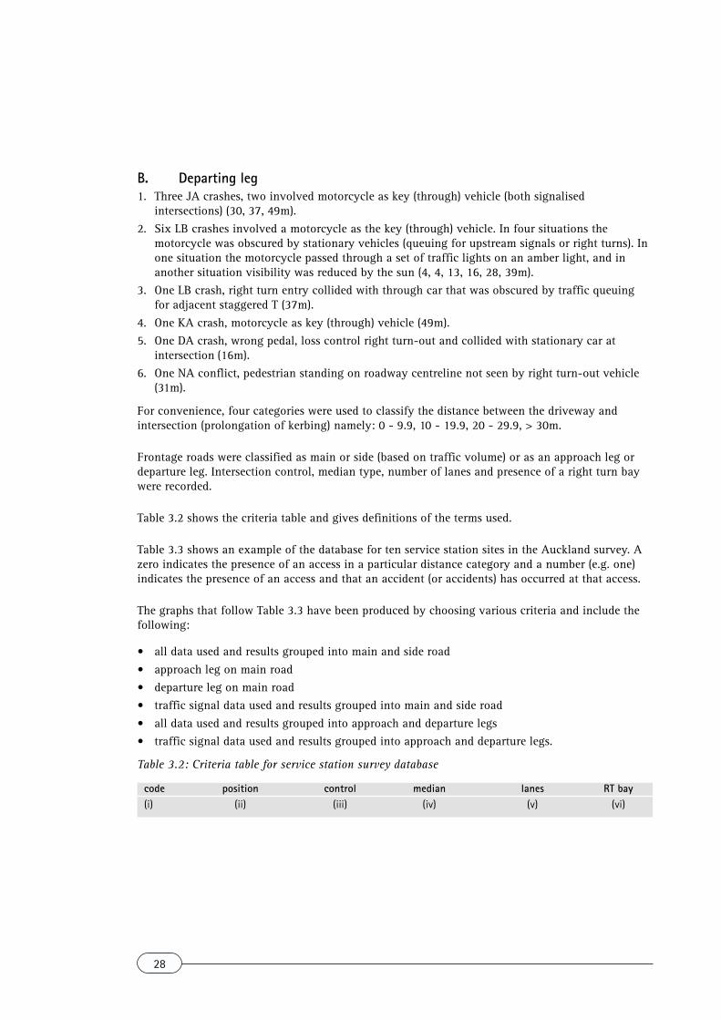
Table 3.2 shows the criteria table and gives definitions of the terms used.
Table 3.3 shows an example of the database for ten service station sites in the Auckland survey. Azero indicates the presence of an access in a particular distance category and a number (e.g. one)indicates the presence of an access and that an accident (or accidents) has occurred at that access.
The graphs that follow Table 3.3 have been produced by choosing various criteria and include thefollowing:
• all data used and results grouped into main and side road• approach leg on main road• departure leg on main road• traffic signal data used and results grouped into main and side road• all data used and results grouped into approach and departure legs• traffic signal data used and results grouped into approach and departure legs.
Table 3.2: Criteria table for service station survey database
code position control median lanes RT bay(i) (ii) (iii) (iv) (v) (vi)

29
Definitions(i) code: specific station I.D., e.g. A19 is Auckland sample station number 19(ii) position: A = station located on the approach to the intersection, D = station located on the
departure from the intersection(iii) control: type of control at intersection (TS = traffic signals, GW = give way, S = stop, R =
roundabout, Nil = uncontrolled)(iv) median: median type on the main road (S = solid, F = flush, N = none)(v) lanes: number of lanes on the main road(vi) RT bay: Y = right turn bay on the main road
Note: A blank criteria table will extract and present all the data from the database.

30
Code
Posi
tion
Med
ian
Lane
sRT
cont
rol
(F/S
/N)
bay
A01
DTS
N4
A02
AN
ILN
2A0
3D
TSN
4Y
A04
ATS
N3
A05
DG
WN
3Y
A06
DTS
N2
A07
AN
ILN
4A0
8D
TSN
3A0
9D
TSS
4Y
A10
DG
WN
2Y
Nea
rest
driv
eway
to
int.
0-9m
10-1
9m20
-29m
30+
01
1
0 01 0
00
Furt
hest
d/w
ay f
rom
int.
0-9m
10-1
9m20
-29m
30+ 1
00 0 0 0 2
Nea
rest
driv
eway
to
int.
0-9m
10-1
9m20
-29m
30+
0 00
00
10
Mai
n ro
ad c
rash
esFu
rthe
st d
/way
fro
m in
t.0-
9m10
-19m
20-2
9m30
+ 0
Side
roa
d cr
ashe
s
Table 2.3: Service station surveydatabase (sample)

31
0%
10%
20%
30%
40%
50%
0-9 10-19 20-29 30+
Driveway distance from main road (metres)
% of driveways
% of crashes
0%
10%
20%
30%
40%
50%
0-9 10-19 20-29 30+
Driveway distance from side road (metres)
% of driveways
% of crashes
Criteria table for service station survey database
code position control median lanes RT bay
Results for the main road Results for the side road0-9m 10-19m 20-29m 30+ 0-9m 10-19m 20-29m 30+
No. of driveways 14 23 13 42 12 20 12 24% of driveways 15% 25% 14% 46% 18% 29% 18% 35%No. of crashes 5 2 3 8 0 4 2 4% of crashes 28% 11% 17% 44% 0% 40% 20% 40%Crashes/driveway 0.36 0.09 0.23 0.19 0.00 0.20 0.17 0.17
Location of driveway versus crashes
Main road accesses
Location of driveway versus crashes
Side road accesses

32
0%
20%
40%
60%
80%
0-9 10-19 20-29 30+
Driveway distance from main road (metres)
% of driveways
% of crashes
0%
10%
20%
30%
40%
50%
0-9 10-19 20-29 30+
Driveway distance from side road (metres)
% of driveways
% of crashes
Criteria table for service station survey database
code position control median lanes RT bayA
Results for the main road Results for the side road0-9m 10-19m 20-29m 30+ 0-9m 10-19m 20-29m 30+
No. of driveways 5 11 5 18 2 12 5 11% of driveways 13% 28% 13% 46% 7% 40% 17% 37%No. of crashes 2 2 1 2 0 2 0 1% of crashes 29% 29% 14% 29% 0% 67% 0% 33%Crashes/driveway 0.40 0.18 0.20 0.11 0.00 0.17 0.00 0.09
Location of driveway versus crashes
Main road accesses
Location of driveway versus crashes
Side road accesses

33
0%
10%
20%
30%
40%
50%
0-9 10-19 20-29 30+
Driveway distance from main road (metres)
% of driveways
% of crashes
0%
10%
20%
30%
40%
50%
60%
0-9 10-19 20-29 30+
Driveway distance from side road (metres)
% of driveways
% of crashes
Criteria table for service station survey database
code position control median lanes RT bayD
Results for the main road Results for the side road0-9m 10-19m 20-29m 30+ 0-9m 10-19m 20-29m 30+
No. of driveways 9 12 8 24 10 8 7 13% of driveways 17% 23% 15% 45% 26% 21% 18% 34%No. of crashes 3 0 2 6 0 2 2 3% of crashes 27% 0% 18% 55% 0% 29% 29% 43%Crashes/driveway 0.33 0.00 0.25 0.25 0.00 0.25 0.29 0.23
Location of driveway versus crashes
Main road accesses
Location of driveway versus crashes
Side road accesses

34
0%
10%
20%
30%
40%
50%
60%
0-9 10-19 20-29 30+
Driveway distance from main road (metres)
% of driveways
% of crashes
0%10%20%30%40%50%60%70%
0-9 10-19 20-29 30+
Driveway distance from side road (metres)
% of driveways
% of crashes
Criteria table for service station survey database
code position control median lanes RT bayTS
Results for the main road Results for the side road0-9m 10-19m 20-29m 30+ 0-9m 10-19m 20-29m 30+
No. of driveways 3 7 6 24 2 9 4 14% of driveways 8% 18% 15% 60% 7% 31% 14% 48%No. of crashes 1 0 2 3 0 3 2 4% of crashes 17% 0% 33% 50% 0% 33% 22% 44%Crashes/driveway 0.33 0.00 0.33 0.13 0.00 0.33 0.50 0.29
Location of driveway versus crashes
Main road accesses
Location of driveway versus crashes
Side road accesses

35
0%
10%
20%
30%
40%
50%
60%
0-9 10-19 20-29 30+
Driveway distance from intersection (metres)
% of driveways
% of crashes
0%
10%
20%
30%
40%
50%
0-9 10-19 20-29 30+
Driveway distance from intersection (metres)
% of driveways
% of crashes
All approaches and all departures
Results for the main road Results for the side road0-9m 10-19m 20-29m 30+ 0-9m 10-19m 20-29m 30+
No. of driveways 15 19 12 31 11 24 13 35% of driveways 19% 25% 16% 40% 13% 29% 16% 42%No. of crashes 2 5 3 5 3 2 2 7% of crashes 13% 33% 20% 33% 21% 14% 14% 50%Crashes/driveway 0.13 0.26 0.25 0.16 0.27 0.08 0.15 0.20
Location of driveway versus crashes
All approach data
Location of driveway versus crashes
All departure data

36
0%
10%
20%
30%
40%
50%
60%
0-9 10-19 20-29 30+
Driveway distance from intersection (metres)
% of driveways
% of crashes
0%
10%
20%
30%
40%
50%
60%
0-9 10-19 20-29 30+
Driveway distance from intersection (metres)
% of driveways
% of crashes
All approaches and all departures at traffic signals
Results for the main road Results for the side road0-9m 10-19m 20-29m 30+ 0-9m 10-19m 20-29m 30+
No. of driveways 3 5 5 16 2 11 5 22% of driveways 10% 17% 17% 55% 5% 28% 13% 55%No. of crashes 1 2 3 5 0 1 1 2% of crashes 9% 18% 27% 45% 0% 25% 25% 50%Crashes/driveway 0.33 0.40 0.60 0.31 0.00 0.09 0.20 0.09
Location of driveway versus crashes
All approaches to signalised intersections
Location of driveway versus crashes
All departures from signalised intersections

37
Appendix 4: Driveway distance formula
Table 4.1 shows the formulae used to calculate the minimum distance a driveway should be from anintersection (prolongation of kerbing).
Table 4.1: Minimum distance of driveway from intersection

38
Appendix 5: Crash types

39
Appendix 6: Visibility
The following extracts regarding visibility are taken from RTS 6 - Guidelines for visibility atdriveways [7].
6.1 Sight distance
Table 6.1: Sight distances
Minimum sight distance (metres)** Frontage road classification
Local Collector ArterialDriveway classifications Operating speed (km/h)*Low volume 40 30 35 70Up to 200 vehicle manoeuvres per day 50 40 45 90
60 55 65 11570 85 85 14080 105 105 17590 130 130 210
100 160 160 250110 190 190 290120 230 230 330
High volume 40 30 70 70More than 200 vehicle manoeuvres per day 50 40 90 90
60 55 115 11570 85 140 14080 105 175 17590 130 210 210
100 160 250 250110 190 290 290120 230 330 330
* Operating speed = 85th percentile speed on frontage road. This can be taken as the speed limitplus 15% if survey data are not available.
** Distances are based on the Approach Sight Distance and Safe Intersection Sight Distance tablesin Austroads, Intersections at Grade [4] assuming reaction times of 1.5 seconds on local roadswith operating speeds up to 60 km/h, and 2.0 seconds for all other speeds and all collector andarterial roads.
Sight distance is measured along the vehicle path shown in Figure 6.1.

40
��������
��� �������
������ �� ����
��� �������
���
� �
���
� �
��������
��� �������
������ �� ����
��� �������
���
� �
���
� �
��������
�� ���� ������ �� ���� ������ ��������
���
� �
���
� �
��
��������
�� ���� ������ �� ���� ������ ��������
���
� �
���
� �
��
Figure 6.1: Sight distance measurement
6.2 Lines of clear sight
There should be lines of clear sight from driver’s eye height to driver’s eye height (1.15 metresabove ground level) along the lines detailed below and shown in Figure 6.2.
• Lines AC and BD - All driveways, all roads• Lines EC and ED (no permanent obstructions, exclude parked vehicles which may obstruct these
sight lines occasionally)- High volume driveway, collector road- Low volume driveway, arterial road in urban area
• Lines EC and ED (no obstructions, parked vehicles not excluded)- Low volume driveway, arterial road in rural area- High volume driveway, arterial road.
Figure 6.2: Lines of clear sight
The procedure of establishing adequate sight distance and lines of clear sight should be undertakenfor all driveways at the service station site.
RTS 6 - Guidelines for visibility at driveways [7] should be consulted if an in-depth knowledge ofthe design principles for visibility at driveways is required.
Points A, B, C and Dare as shown in Figure6.2, with points C andD established bymeasuring the sightdistance from Table 6.1along the centre of theappropriate lane frompoints A and B.

41
Appendix 7: Glossary of terms
Driveway A means of vehicle access between the roadway and the service stationsite, e.g. footpath crossover.
Flush median A flush median is an area of white diagonal lines normally painted downthe middle of the road. The area is bounded by approximately parallellongitudinal white lines. Flush medians are used to separate opposinglanes of traffic and provide a place for vehicles that are waiting to turnright, are waiting to merge with traffic, or provide pedestrian refugeareas.
Head of the T The length of the road boundary opposite the side road of a T-shapedintersection. The extended road boundaries of the side road determinethe length of the head of the T.
Intersection The area outlined by extensions of the road boundaries where two ormore roads intersect.
Intersection site A site with crashes located 70m or less from an intersection in an urbanspeed environment (< 70 km/h) and 210m or less in a rural speedenvironment (> 70 km/h).
Road boundary The legal boundary between the road reserve and adjoining land use, e.g.a service station.
Road reserve The entire area of legal road, including roadway, footpath and berms(grassed area between roadway and footpath).
Roadway The portion of the road reserve used by vehicles. It includes traffic lanes,parking lanes and metal shoulders, but not footpaths or berms.
Rural Speed environment > 70 km/h.
Solid median A traffic island (raised above the roadway surface) used to channel andto separate different streams of traffic on the roadway or to providerefuge for pedestrians crossing the roadway.
Urban Speed environment < 70 km/h.
VPH Vehicles per hour. The number of vehicles passing a fixed point on aroadway per hour.

42
Road and Traffic Guideline publications
The following Road and Traffic Guidelines are available:
RTS 1 Guidelines for the implementation of traffic control at crossroads (1990)
RTS 2 Guidelines for street name signs (1990)
RTS 3 Guidelines for establishing rural selling places (1992)
RTS 4 Guidelines for flush medians (1991)
RTS 5 Guidelines for rural road marking and delineation (1992)
RTS 6 Guidelines for visibility at driveways (1993)
RTS 7 Advertising signs and road safety: design and location guidelines (1993)
RTS 8 Guidelines for safe kerbline protection (1993)
RTS 9 Guidelines for the signing and layout of slip lanes (1994)
RTS 11 Urban roadside barriers and alternative treatments (1995)
RTS 13 Guidelines for service stations (1995)
RTS 14 Guidelines for installing pedestrian facilities for people with visual impairment (1997)
RTS 17 Guidelines for setting speed limits (1995)
The Guidelines may be purchased from:
Land Transport Safety Authority, Head Office (PO Box 2840, Wellington) or Regional Offices in:Auckland, (Private Bag 106 602), Wellington (PO Box 27 249) and Christchurch (PO Box 13 364).