guide for installation of acss & acss/tw conductor · pdf filefigure 1. comparison of acss...
TRANSCRIPT
GUIDE FOR INSTALLATION OF ACSS & ACSS/TW CONDUCTOR

TABLE OF CONTENTS
Introduction 1
Reel Handling and Storage 2
Conductor Handling 3
Payoff 3
Bullwheel 4
Stringing Sheaves 5
Conductor Stringing and Sagging 6
Conductor Grips 7
Dead-Ends and Splices 9
Prestressing 10
Spooling and Training 11
Conductor Oxidation 12
Conductor Staining 13
Sagging Methods 14
Vibration Dampers 15
Suspension Clamps 17
Hardware Manufacturer Links 18
Southwire’s Aluminum Conductor, Coated-Steel
Supported (ACSS) and Trapezoidal-Shaped Wire
Aluminum Conductor, Coated-Steel Supported (ACSS/TW)
are aluminum conductors with a stranded steel core for
use as the primary support member. ACSS conductors have round wire aluminum
strands, while ACSS/TW conductors have trapezoidal-shaped aluminum strands for
increased ampacity for the same diameter, or reduced
diameter for the same conductor size.

Figure 1. Comparison of ACSS and ACSS/TW conductors.
Although similar in appearance, ACSS and ACSR are mechanically and electrically different. The aluminum wires in ACSR are extra-hard drawn 1350-H19, while the aluminum wires in ACSS are 1350-O temper, or soft drawn. Since the annealed aluminum wires are softer, they exhibit increased ductility and conductivity but decreased tensile strength. Due to the softness of the wires, ACSS is more susceptible to surface abrasion than ACSR. Consequently, more care should be taken during installation of ACSS to ensure proper handling of the conductor.1
ACSS installs in a manner similar to ACSR. However, ACSS is less forgiving of improperly sized or damaged equipment and “shortcuts.” Southwire recommends that all conductor installations be performed in accordance with IEEE 524 “Guide to the Installation of Overhead Transmission Line Conductors.” This guide is intended to summarize best practices for installing ACSS and ACSS/TW conductors.
Introduction
1
1 IEEE Standard 524-2002 pg. 75

REEL HANDLING AND STORAGE
While reel handling and storage guidelines do apply equally for all conductors, special care should be taken to ensure that ACSS conductor and reels are not damaged. Unloading equipment must never come in contact with the conductor. Lifting must be performed using a fork lift or crane as described below.
When using a fork lift, the forks shall be placed under both flanges, with the flange facing the operator.
When using a crane, a spreader bar must be used in conjunction with either “J” hooks or an axle to prevent damage to the reel flange and conductor. “J” hooks should be placed in the arbor holes. Axles should be inserted through the arbor holes and lifted with straps.
Reels should be stored away from physical and environmental hazards, such as chemicals. Conductor reels must be stored standing on their flanges in a flat, well-drained area. The conductor must not be allowed to touch the ground.
Figure 2. Forklift handling of reels.
Figure 3. Crane handling of reels.
Reel Handling and Storage
2

2 IEEE Standard 524-2002 pg. 593 IEEE Standard 524-2002 pg. 75
4 IEEE Standard 524-2002 pg. 665 IEEE Standard 524-2002 pg. 75
CONDUCTOR HANDLING2
Additional emphasis should be placed on normal precautions to avoid scuffing the surface of ACSS conductor. ACSS conductor should not be dragged across any surface. If conductor must contact the ground due to unavoidable circumstances, a smooth,
rigid material may be laid in its path to prevent damage. Minor abrasions should not be a cause of concern; most can be sanded or buffed out. In an EHV application, the abrasion should be evaluated for possible corona concerns.
PAYOFF
The conductor reel should be set up on a reel payoff stationed 40-50 feet behind and in line with the bullwheel tensioner. This will ensure that the conductor does not scrub the flanges as it is being unwound.3
Aligning the payoff and bullwheel will help to avoid scuffing of the conductor against adjacent conductor turns or against the reel flange.4 Proper adjustment of the fairlead roller guides is necessary to prevent scuffing of the conductor as it reeves through the bullwheel. Reels are only designed to transport the conductor; they are not designed for use as tensioning devices. As with any conductor, minimal braking tension should be applied to the payoff to prevent damage to the conductor or reel. Only enough braking tension should be applied to the reel to prevent the reel from over-rotating (free-spooling) when the pulling operation stops. A slight droop between the payoff and bullwheel is desirable, as this indicates low tension between the bullwheel and payoff.
Back tension should be kept at a minimum. This is especially important for smaller conductor diameters and wooden reels5. If too much back tension is applied, the conductor on the outer layer can “pull down” into the underlying layers, as in Figure 5.
Figure 4. Payoff and bullwheel setup.
Figure 5. Conductor pulldown
Conductor Handling
3
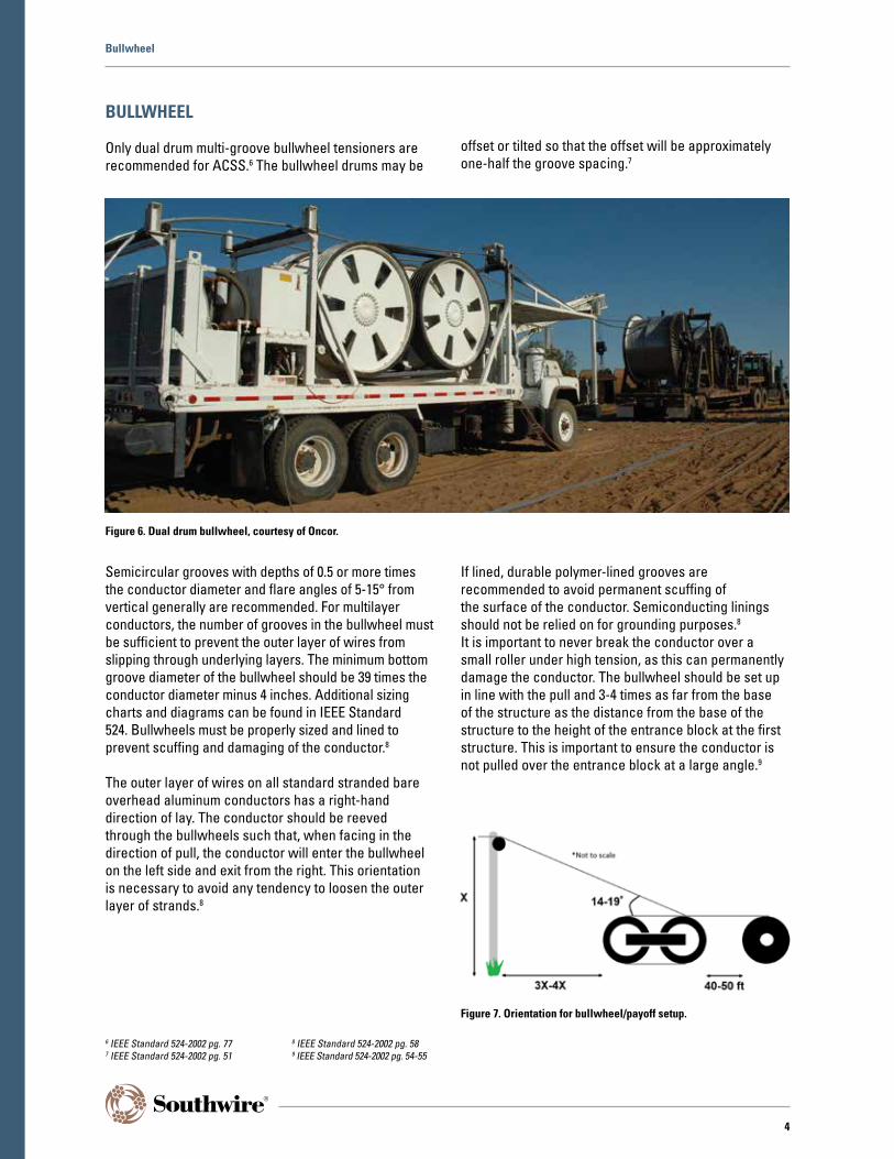
BULLWHEEL
Only dual drum multi-groove bullwheel tensioners are recommended for ACSS.6 The bullwheel drums may be
offset or tilted so that the offset will be approximately one-half the groove spacing.7
Bullwheel
Semicircular grooves with depths of 0.5 or more times the conductor diameter and flare angles of 5-15° from vertical generally are recommended. For multilayer conductors, the number of grooves in the bullwheel must be sufficient to prevent the outer layer of wires from slipping through underlying layers. The minimum bottom groove diameter of the bullwheel should be 39 times the conductor diameter minus 4 inches. Additional sizing charts and diagrams can be found in IEEE Standard 524. Bullwheels must be properly sized and lined to prevent scuffing and damaging of the conductor.8
The outer layer of wires on all standard stranded bare overhead aluminum conductors has a right-hand direction of lay. The conductor should be reeved through the bullwheels such that, when facing in the direction of pull, the conductor will enter the bullwheel on the left side and exit from the right. This orientation is necessary to avoid any tendency to loosen the outer layer of strands.8
If lined, durable polymer-lined grooves are recommended to avoid permanent scuffing of the surface of the conductor. Semiconducting linings should not be relied on for grounding purposes.8
It is important to never break the conductor over a small roller under high tension, as this can permanently damage the conductor. The bullwheel should be set up in line with the pull and 3-4 times as far from the base of the structure as the distance from the base of the structure to the height of the entrance block at the first structure. This is important to ensure the conductor is not pulled over the entrance block at a large angle.9
Figure 6. Dual drum bullwheel, courtesy of Oncor.
6 IEEE Standard 524-2002 pg. 777 IEEE Standard 524-2002 pg. 51
8 IEEE Standard 524-2002 pg. 589 IEEE Standard 524-2002 pg. 54-55
Figure 7. Orientation for bullwheel/payoff setup.
4

STRINGING SHEAVES10
Sizing recommendations for sheaves should be made by the sheave manufacturer, but typical sizing criteria are discussed below.
A minimum bottom groove diameter of 20 times the conductor diameter is recommended, although higher tension pulls, or structures with a turning angle greater than 20°, may warrant larger sheaves. For angles between 20-45°, a bottom groove diameter of 25 times the conductor diameter is typically recommended. For angles up to 90°, two sheaves with bottom groove diameters of 25 times the conductor diameter are typically recommended. Sheaves on structures with a turning angle should be supported so that the conductor acts through the center line of the sheave. Measurement A in Figure 8 below shows where to measure the bottom groove diameter.
The minimum radius at the base of the groove is recommended to be 1.1 times the radius of the conductor. The location of this measurement is shown as Measurement B in Figure 8. Sheaves with a groove radius as above may, in general, be used with smaller conductors. However, the more layers of aluminum that exist, the more important it is to have a well-fitting groove.
The minimum depth of the groove should be 1.25 times the conductor diameter. This measurement is given as Measurement C in Figure 8. The flare of the grooves should be between 12-20° from vertical to facilitate the passage of swivels, grips, etc., and to contain the conductor for angled pulls.
If lined, sheaves should be lined with a durable polymer to protect against scratching of the conductor. Sheave bearings must be in good working condition and free-wheeling.
Rough handling of sheaves can result in inadequate performance, so make sure all sheaves are in proper working order before use.
Figure 8. Measurements for stringing sheave.
Figure 9. Stringing sheave.
10 IEEE Standard 524-2002 pg. 63
Stringing Sheaves
5

Table 1. Common Conductors And Sheave Requirements
Conductor Overall DiameterMinimum Bottom Groove Diameter Minimum Groove Radius
at Base Minimum Groove DepthStandard Tangent
in in in in in
Partridge/ACSS 0.642 12.84 8.84 0.353 0.803
Linnet/ACSS 0.720 14.40 10.40 0.396 0.900
Hawk/ACSS 0.858 17.16 13.16 0.472 1.073
Dove/ACSS 0.927 18.54 14.54 0.510 1.159
Drake/ACSS 1.108 22.16 18.16 0.609 1.385
Cardinal/ACSS 1.196 23.92 19.92 0.658 1.495
Curlew/ACSS 1.245 24.90 20.90 0.685 1.556
Falcon/ACSS 1.545 30.90 26.90 0.850 1.931
Bluebird/ACSS 1.762 35.24 31.24 0.969 2.203
RUNNING GROUNDS11
Running grounds should be installed along two points in the pull—one between the reel stand or tensioner and first structure, and the other between the puller and last structure. Running grounds should be bonded to the established ground and free-wheeling. They should not be over tightened, as this could cause surface abrasion or birdcaging.
CONDUCTOR STRINGING AND SAGGING
To avoid damaging the conductor, tension stringing is recommended.12 The maximum recommended pulling tension during the stringing operation should not exceed that necessary to maintain clearances above obstructions on the ground or safety structures. Recommended stringing tensions13 are between 5-10% of the rated breaking strength of the conductor and should not exceed 50% of sagging tensions. In circumstances where the tension must exceed 50% of sagging tensions, contact Southwire for a recommendation on creep correction. Typical pulling speeds are between 3-5 miles per hour.14
Southwire recommends that any conductor be pulled up to sag and clipped in as soon as possible. The conductor should not be left in the sheaves for more than 24 hours before being pulled up to sag. If tension must be reduced after sagging (due to vibration concerns, equipment availability, etc.), the attachment points should be marked immediately after sagging. The conductor should be clipped in within 72 hours.15 If a conductor must be left in the sheaves for an extended period of time, it should be left at a tension less than 50% of sagging tension (close to pulling tension). If this tension is exceeded, contact Southwire for a recommendation on creep correction.
Conductor Stringing and Sagging
11 IEEE Standard 524-2002 pg. 7512 IEEE Standard 524-2002 pg. 52
13 IEEE Standard 524-2002 pg. 6614 IEEE Standard 524-2002 pg. 74
15 IEEE Standard 524-2002 pg. 75
6
CONDUCTOR GRIPS16
Southwire does not recommend nor take responsibility for the use of any conductor grips. All grips must first be approved by the grip manufacturer for use with ACSS.
All grips used for ACSS must be of the transmission grade. The jaws of transmission grade grips are longer to ensure more gripping area on the conductor. Grip jaws may be round or oval but not V-shaped. Grips must be properly sized for the conductor type, conductor diameter, and tensions to be installed. Ranging grips that accept a range of conductor sizes, e.g. 1/0-4/0 AWG, should not be used. Certain high-tension applications require the use of tandem grips. If the required tension exceeds the safe load of a single grip, two grips must be used in tandem. Please refer to the Prestressing section for more information on the use of tandem grips.
Prior to use, grips must be inspected to ensure they are in good operating condition and tested for holding strength on the conductor to be installed. Southwire recommends taking a section of the conductor to be installed and, using two line trucks as temporary anchors, testing the holding strength of the grips using a chain hoist and dynamometer to verify grip holding strength. During testing, grips should not slip when subjected to a minimum tension of 110% of the working tension during installation. The following grips are commonly used with ACSS conductor:
A swivel is required between the basket grip and pull line or between grips if multiple reels are tied together (double-socked) for longer pulls. The swivel will allow the conductor to rotate freely during the pulling process.
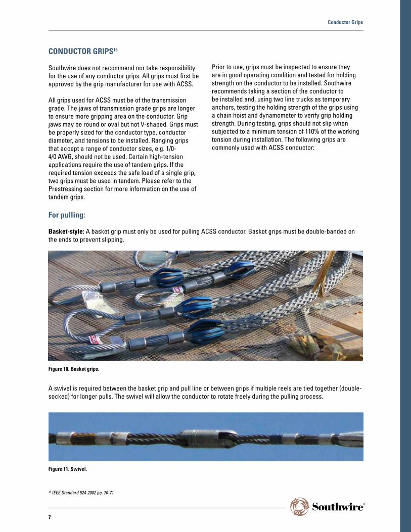
For pulling:
Basket-style: A basket grip must only be used for pulling ACSS conductor. Basket grips must be double-banded on the ends to prevent slipping.
Figure 10. Basket grips.
Figure 11. Swivel.
Conductor Grips
16 IEEE Standard 524-2002 pg. 70-71
7

Other grips may be determined to be applicable for use with ACSS. Any grips should be qualified by the manufacturer for use with ACSS and should be tested prior to use.
Some manufacturers publish their grip ratings based on use with ACSR conductors and then derate them for use
with ACSS conductors. The lower rating is necessary because the grips must hold onto the fully annealed aluminum in ACSS as opposed to the hardened aluminum in ACSR. Check with the grip manufacturer for a recommendation before using any grip with ACSS conductors.
Conductor Grips
Pocketbook-style: These grips have also been used with ACSS. Bolts on pocketbook-style grips, or comealongs, must be cleaned and well lubricated. Pull tests for grips must be conducted per the manufacturer requirements.
The bolts must be snugged-up and then tightened with at least five passes applying full torque recommended by the manufacturer.
Figure 13. Pocketbook-style grip.
For sagging:
Klein “Chicago-style”17: Chicago grips are the most commonly used sagging grip. For conductor diameters 0.953” and smaller, Klein grips should be of catalog number 1656-XX and used in tandem. For conductor diameters larger than 0.953”, grips should be catalog number 1628-50. Grips should be closely sized for the conductor diameter to minimize strand distortion. For applications where the load is expected to exceed 10,000 lb or 40% RBS, use two grips in tandem.
Figure 12. Klein “Chicago-style” grip.
8
17 ”Wire Pulling Grip Guide.” Klein Tools, Sept. 2015. Web.

Proper installation of ACSS hardware will ensure that birdcaging does not occur. When compression fittings are crimped, the fully annealed aluminum in ACSS tends to extrude more than the hardened aluminum in ACSR. For this reason, special steps must be taken to avoid
excessive birdcaging during installation of compression dead-ends and splices. Check with the hardware manufacturer for their recommendations for ACSS conductors.
DEAD-ENDS AND SPLICES
Southwire does not recommend, nor take responsibility, for the use of any conductor hardware. All dead-ends and splices must first be approved by the hardware manufacturer for use with ACSS.
The compression hardware for ACSS is similar to the type used for ACSR. However, the ACSS hardware must be able to handle the higher current densities present in ACSS. ACSS hardware has more aluminum and has been tempered to handle the high operating temperatures. ACSS dead-ends should have NEMA four hole pads. All compression hardware for ACSS must be
two-piece. Two-piece compression hardware has a steel sleeve or eye for the steel core and an aluminum sleeve for the conductor.
Bolted dead-ends, strain clamps, and automatic splices are not recommended. Bolted T-taps are suitable pending hardware manufacturer approval.
Formed wire and implosive dead-ends and splices have been successfully used on ACSS. Check with your hardware manufacturer for a recommendation on the use of these types of hardware on ACSS.
Because of the high operating temperature of ACSS, corrosion inhibitors should be specified as suitable for high temperature use.
Figure 14. Compression dead-end.
Dead-Ends and Splices
9
PRESTRESSING
Prestressing is a method used to reduce future creep in the conductor. It can also increase the self-damping
capability. Consult with your damper suppliers for damping requirements and recommendations.
The rated strength of a tandem configuration is 150% of the lowest rated grip. For example, if one grip is rated for 6,000 lb and the other for 7,500 lb, the two in tandem would be rated 9,000 lb (6,000 X 1.5).
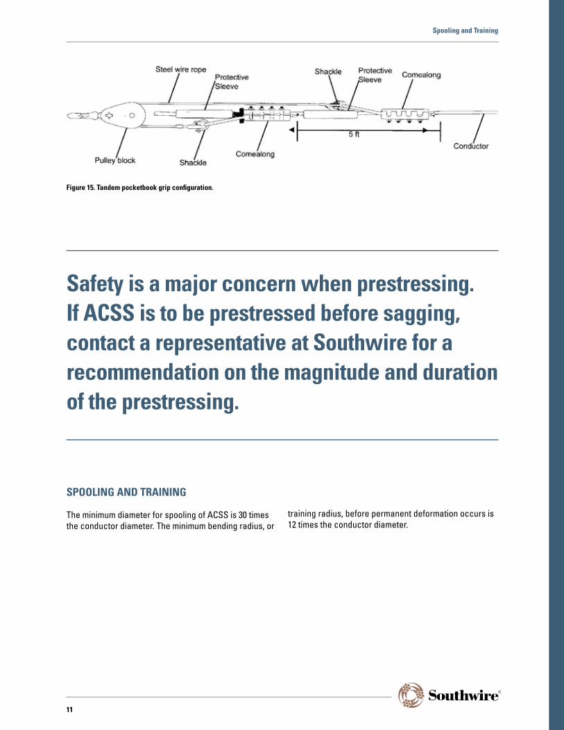
In tandem configurations, the grip bails should be bridled with a sling, consisting of shackles and wire rope, and pulley block to ensure equal distribution of the load. Protective sleeves should be placed over the conductor at each shackle location to prevent damage. Tandem grip configurations should be tested for grip strength prior to use.
Prestressing
When prestressing ACSS, tandem grips must be used along with a conventional core gripping method to avoid slip during high tension.
10
Safety is a major concern when prestressing. If ACSS is to be prestressed before sagging, contact a representative at Southwire for a recommendation on the magnitude and duration of the prestressing.
SPOOLING AND TRAINING
The minimum diameter for spooling of ACSS is 30 times the conductor diameter. The minimum bending radius, or
training radius, before permanent deformation occurs is 12 times the conductor diameter.
Figure 15. Tandem pocketbook grip configuration.
Spooling and Training
11

CONDUCTOR OXIDATION
Oxidation results from a chemical reaction between oxygen and aluminum, yielding an oxide layer on the conductor. While it is normal for oxidation to form, necessary steps should be taken to clean the
conductor of oxidation at hardware application areas. The conductor must be brushed in these areas prior to installing hardware to ensure adequate metal-to-metal contact.
Figure 16. Oxidation on a conductor.
Conductor Oxidation
Exposure of conductor to air will cause oxidation to form on the conductor.
12

CONDUCTOR STAINING
When conductor reels are stored outdoors, moisture can accumulate on the conductor on the underside of the reel. If the moisture contains chemicals from the surrounding atmosphere, a black stain known as a “water stain” can
appear on the conductor. This has been found to be more prevalent in non-specular conductor because the drawing oils have been removed. Figure 17 shows the appearance of a water stain.
Water stains are a cosmetic issue; they have no adverse effect on the performance or service life of the conductor.
In most environments, the conductor will darken in the first few months after the line is energized, and the stain will no longer be noticeable. Aluminum Association Technical Bulleting TR3, “Guidelines for Minimizing
Water Staining of Aluminum” discusses this issue in detail and contains advice for avoiding conductor staining.
No corrosion in excess of normal oxidation results from the water stain.
Figure 17. Water stain on conductor.
Conductor Staining
13
SAGGING METHODS18
Conductor sagging involves the use of stringing tables to determine the required sag or tension at a specific conductor temperature. Conductor temperature should be measured at the time of sagging using a conductor
thermometer placed at or near the conductor. The conductor thermometer should be installed prior to sagging to allow for temperature stabilization.
Transit MethodThe transit method includes three types of sagging methods: calculated angle of sight, calculated target, and horizontal line of sight. Choice of the best transit sagging method to use is determined by the terrain of the span in the right-of-way and span length. Tall structures on flat terrain and short spans indicate the calculated target or horizontal line of sight method would be most applicable. Steep slopes, long spans, and large sags indicate the calculated angle of sight method would be best.
Dynamometer MethodIn the dynamometer method, a dynamometer is inserted in-line with the sagging equipment to get a direct measurement of line tension. To ensure accurate sagging, there should be minimal sheaves in the line section. This method works best on smaller conductors, shorter spans, and ruling spans containing one or two spans.
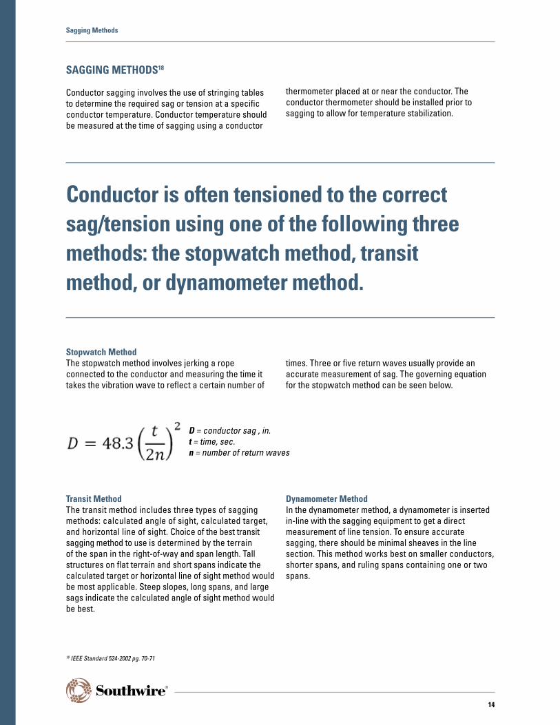
Stopwatch MethodThe stopwatch method involves jerking a rope connected to the conductor and measuring the time it takes the vibration wave to reflect a certain number of
times. Three or five return waves usually provide an accurate measurement of sag. The governing equation for the stopwatch method can be seen below.
Sagging Methods
D = conductor sag , in.t = time, sec.n = number of return waves
18 IEEE Standard 524-2002 pg. 70-71
Conductor is often tensioned to the correct sag/tension using one of the following three methods: the stopwatch method, transit method, or dynamometer method.
14

VIBRATION DAMPERS
Under most conditions, the self-damping capability of ACSS activated by prestressing will greatly lessen or eliminate the need to install vibration dampers. However, if the conductor is not prestressed, dampers may be necessary to protect the conductor until the conductor
has activated its self-damping capability through electrical and mechanical loading. Recommendations on type and placement of dampers on ACSS lines should be made by the damper manufacturer.
Many dampers utilize armor rods to provide added protection for ACSS.
ACSS is suitable for bundling applications. When using dampers, cushioning inserts or line guards are recommended to protect ACSS conductor.
Figure 18. Stockbridge damper, courtesy of AFL Global.
Vibration Dampers
Check with your damper manufacturer for their recommendations on use of armor rods with dampers.
15

SUSPENSION CLAMPS
Since ACSS conductor features fully annealed aluminum, proper hardware must be chosen to ensure the conductor will not be damaged in the clamps. The suspension hardware must be rated to handle temperatures up to 250°C. Aluminum or cushioned-type
clamps are suitable for use with ACSS. When using bolted clamps, armor rods are recommended with standard clamps.
Figure 19. Armor-Grip Suspension units, courtesy of PLP.
Suspension Shoes
Use of these will help to protect the fully annealed aluminum from damage by the shoes.
16

Hardware manufacturers have hardware designed for use with ACSS. Please consult the hardware manufacturer for their recommendation on use of armor rods or a repair sleeve.
CONDUCTOR REPAIR
Since ACSS is primarily supported by the steel core, damage or loss of an aluminum strand does not significantly affect the strength of ACSS conductor. However, a reduction of the current carrying ability does occur. The conductor will operate hotter if one or
more strands are broken. If conductor temperature becomes an issue, then repair of the conductor may be necessary. Line carts may be used to aid in the repair process.
Conductor Repair
Repair methods may include use of armor rods or a repair sleeve to reestablish the full current carrying capacity.
17

HARDWARE MANUFACTURER LINKS
For more information on conductor hardware, including splices, dead-ends, grips, armor rod, repair sleeves, dampers, and suspension shoes, please see the hardware manufacturer websites below.
AFL: http://www.aflglobal.com/Home.aspx
Preformed Line Products (PLP): http://www.preformed.com/
Hubbell: http://www.hubbell-wiring.com/productinformation/viewcatalog.aspx?Dest=hubbell-wiring.com/press/catalog/t.pdf
http://www.hubbellpowersystems.com/connectors/trans/
Burndy: http://www.burndy.com/
MacLean: http://www.macleanpower.com/
REFERENCES
“Wire Pulling Grip Guide.” Klein Tools, Sept. 2015. Web.
IEEE Standard 524-2002, “Guide to the Installation of Overhead Transmission Line Conductors.”
Thrash, Ridley, Kim Nuckles, Amy Murrah, and Mark Lancaster. Overhead Conductor Manual 2nd Edition. N.p.: Southwire, 2007. Print.
DISCLAIMER
This publication is a collection of items of general information related to the subject of ACSS conductor. It is not intended to be nor should it be used as authority for design, construction, use, or installation. The design, construction, use, and installation of ACSS conductor should only be undertaken by competent professionals in light of currently accepted design and engineering practices. While great care has been employed to ensure that the applications, tables, standards, references, and other information contained herein are free of errors, absolutely no warranties, either expressed or implied, are made as to the accuracy or completeness of any such material contained herein.
THOSE PREPARING AND/OR CONTRIBUTING TO THE PUBLICATION SPECIFICALLY DISCLAIM ANY WARRANTY OF ANY KIND, EITHER EXPRESSED OR IMPLIED. THE WARRANTIES OF MERCHANTABILITY AND FITNESS FOR A PARTICULAR PURPOSE ARE HEREBY SPECIFICALLY DISCLAIMED BY SOUTHWIRE AND ALL OTHER PARTIES INVOLVED IN THE CREATION, PRODUCTION, OR DELIVERY OF THIS PUBLICATION.
Neither Southwire nor anyone else who has been involved in the creation, production, or delivery of this publication shall be liable for any direct, indirect, consequential, or incidental damages arising out of the use, the results of the use, or inability to use such publication, even if Southwire has been advised of the possibility of such damages or claim. Some states do not allow the exclusion or limitation for consequential incidental damages, so the above limitation may not apply to you.
Hardware Manufacturer Links
18


Southwire Company, LLC. • One Southwire Drive • Carrollton, GA 30119 www.southwire.com • 574-596-0030
©2017 Southwire Company, LLC. All Rights Reserved. ®Registered Trademark ™Trademark of Southwire Company, LLC.