guidance for developing integrated water quality ... · pdf file2.1 project management team...
TRANSCRIPT
Guidance for Developing Integrated Water Quality Surveillance and Response Systems
Office of Water (MC 140) EPA 817-B-15-006 October 2015
i
DisclaimerThe Water Security Division of the Office of Ground Water and Drinking Water has reviewed and approved this document for publication. This document does not impose legally binding requirements on any party. The information in this document is intended solely to recommend or suggest and does not imply any requirements. Neither the U.S. Government nor any of its employees, contractors or their employees make any warranty, expressed or implied, or assumes any legal liability or responsibility for any third party’s use of any information, product or process discussed in this document, or represents that its use by such party would not infringe on privately owned rights. Mention of trade names or commercial products does not constitute endorsement or recommendation for use.
Questions concerning this document should be addressed to [email protected] or the following contact:
Steve Allgeier U.S. EPA Water Security Division 26 West Martin Luther King Drive Mail Code 140 Cincinnati, OH 45268 (513) [email protected]
ii
Acknowledgements
The Water Security Division of the Office of Ground Water and Drinking Water would like to recognize the following individuals and organizations for their assistance, contributions, and review during the development of this document.
• James Alair, New York City Department of Environmental Protection • Manouchehr Boozarpour, San Francisco Public Utilities Commission • Geoffrey Brock, City of Philadelphia • Adam Haas, Computer Sciences Corporation • Darcy Shala, Computer Sciences Corporation • Jeff Swertfeger, Greater Cincinnati Water Works
iii
Table of ContentsLIST OF FIGURES .......................................................................................................................................................... V LIST OF TABLES .......................................................................................................................................................... VI ABBREVIATIONS ......................................................................................................................................................... VII SECTION 1: INTRODUCTION ......................................................................................................................................... 1 SECTION 2: PROJECT MANAGEMENT .......................................................................................................................... 3
2.1 Project Management Team ................................................................................................................................. 5 2.2 Component Teams .............................................................................................................................................. 6 2.3 Ongoing Project Coordination ............................................................................................................................ 8
SECTION 3: MASTER PLANNING .................................................................................................................................. 9 3.1 Establish Design Goals and Performance Objectives ....................................................................................... 10 3.2 Identify Project Constraints .............................................................................................................................. 12 3.3 Review Preliminary Component Designs ......................................................................................................... 13 3.4 Consolidate and Prioritize Information Management Requirements ................................................................ 13 3.5 Evaluate SRS Design Alternatives and Select One to Implement .................................................................... 13 3.6 Establish a Project Budget and Schedule ......................................................................................................... 14
SECTION 4: INFORMATION MANAGEMENT ............................................................................................................... 17 4.1 Approaches to Information Management ......................................................................................................... 17
4.1.1 Example of a Manual Information Management System .......................................................................... 17 4.1.2 Example of an Automated Information Management System ................................................................... 18 4.1.3 Example of an Automated and Integrated Information Management System ........................................... 20
4.2 Developing Information Management System Requirements .......................................................................... 22 4.2.1 Develop Preliminary Information Flow Diagrams ................................................................................... 23 4.2.2 Define Functional and Technical Information Management Requirements ............................................. 24 4.2.3 Consolidate and Prioritize Information Management System Requirements ........................................... 26 4.2.4 Finalize Requirements .............................................................................................................................. 28
4.3 Selecting an Information Management System ................................................................................................ 29 4.3.1 Assess Existing Source Data Systems with Respect to Requirements ....................................................... 29 4.3.2 Evaluate Implementation Approaches ...................................................................................................... 30 4.3.3 Select the Solution ..................................................................................................................................... 32 4.3.4 Implement the Solution ............................................................................................................................. 33
4.4 IT Master Planning ........................................................................................................................................... 33 4.4.1 Access Privileges and Security ................................................................................................................. 33 4.4.2 System Adaptability................................................................................................................................... 34 4.4.3 External Hosting of Data or Software ...................................................................................................... 34 4.4.4 System Documentation .............................................................................................................................. 35
SECTION 5: ALERT INVESTIGATION PROCEDURES ................................................................................................... 36 5.1 Assess Existing Resources ............................................................................................................................... 37 5.2 Develop Component Alert Investigation Procedures ....................................................................................... 37 5.3 Review Component Alert Investigation Procedures for Consistency ............................................................... 41
SECTION 6: TRAINING AND EXERCISE PROGRAM..................................................................................................... 43 6.1 Overview of an SRS Training and Exercise Program ...................................................................................... 43 6.2 Discussion-based Exercises .............................................................................................................................. 44
6.2.1 Seminars ................................................................................................................................................... 44 6.2.2 Workshops................................................................................................................................................. 45 6.2.3 Tabletop Exercises .................................................................................................................................... 46
6.3 Operations-based Exercises .............................................................................................................................. 47 6.3.1 Drills ......................................................................................................................................................... 47 6.3.2 Functional and Full-scale Exercises ......................................................................................................... 48
6.4 Implementing an SRS Training and Exercise Program .................................................................................... 49 RESOURCES ................................................................................................................................................................. 51 REFERENCES ............................................................................................................................................................... 53

iv
GLOSSARY ................................................................................................................................................................... 54 APPENDIX A: MASTER PLAN TEMPLATE .................................................................................................................. 62 APPENDIX B: IT OPERATION AND MAINTENANCE MANUAL TEMPLATE ................................................................ 65
v
List of Figures FIGURE 1-1. SURVEILLANCE AND RESPONSE SYSTEM COMPONENTS ............................................................................ 1 FIGURE 1-2. OVERARCHING DESIGN ACTIVITIES AND THE STAGES OF SRS IMPLEMENTATION ..................................... 2 FIGURE 2-1. AREAS OF COORDINATION BETWEEN PROJECT MANAGEMENT AND COMPONENT TEAMS ......................... 5 FIGURE 3-1. OVERVIEW OF THE MASTER PLANNING PROCESS .................................................................................... 10 FIGURE 3-2. OVERVIEW OF THE PROCESS FOR COMPARING SRS DESIGN ALTERNATIVES ........................................... 14 FIGURE 4-1. MANUAL SYSTEM FOR TRACKING WATER QUALITY CUSTOMER COMPLAINTS ....................................... 18 FIGURE 4-2. AUTOMATED CCS DATA ANALYSIS, ALERT NOTIFICATION, AND DATA DISPLAY .................................. 20 FIGURE 4-3. EXAMPLE SRS DASHBOARD .................................................................................................................... 21 FIGURE 4-4. PROCESS FOR DEVELOPING INFORMATION MANAGEMENT SYSTEM REQUIREMENTS .............................. 23 FIGURE 4-5. EXAMPLE INFORMATION FLOW DIAGRAM FOR CCS ................................................................................ 24 FIGURE 4-6. REQUIREMENTS DEVELOPMENT TOOL NAVIGATION PATHWAYS ............................................................ 25 FIGURE 4-7. REQUIREMENTS DEVELOPMENT TOOL – OWQM COMPONENT RATING INTERFACE ............................... 26 FIGURE 4-8. REQUIREMENTS DEVELOPMENT TOOL – IT DESIGN TEAM WORKING VIEW ............................................ 27 FIGURE 4-9. EXAMPLE OF A CCS PHYSICAL ARCHITECTURE DIAGRAM ...................................................................... 28 FIGURE 4-10. PROCESS FOR SELECTING AND IMPLEMENTING AN INFORMATION MANAGEMENT SYSTEM ................... 29 FIGURE 5-1. PROCESS FOR DEVELOPING SRS ALERT INVESTIGATION PROCEDURES ................................................... 36 FIGURE 5-2. EXAMPLE OF A SIMPLIFIED ALERT INVESTIGATION PROCESS DIAGRAM.................................................. 38 FIGURE 5-3. EXAMPLE ALERT INVESTIGATION RECORD.............................................................................................. 40 FIGURE 6-1. PROGRESSION OF AN SRS TRAINING AND EXERCISE PROGRAM .............................................................. 49

vi
List of TablesTABLE 1-1. STAGES OF SRS IMPLEMENTATION ............................................................................................................. 2 TABLE 2-1. UTILITY POSITIONS AND EXTERNAL PARTNERS THAT MAY FORM COMPONENT TEAMS.............................. 7 TABLE 3-1. EXAMPLES OF SRS DESIGN GOALS ........................................................................................................... 11 TABLE 3-2. EXAMPLES OF SRS PERFORMANCE OBJECTIVES ....................................................................................... 12 TABLE 6-1. EXAMPLE SRS SEMINARS ......................................................................................................................... 44 TABLE 6-2. EXAMPLE SRS WORKSHOPS ..................................................................................................................... 46 TABLE 6-3. EXAMPLE SRS TABLETOPS ....................................................................................................................... 47 TABLE 6-4. EXAMPLE SRS DRILLS .............................................................................................................................. 48
vii
Abbreviations AWWA American Water Works Association CCS Customer Complaint Surveillance CM Consequence Management CMP Consequence Management Plan EPA U.S. Environmental Protection Agency ESM Enhanced Security Monitoring GIS Geographic Information System HSEEP Homeland Security Exercise and Evaluation Program ICS Incident Command System IT Information Technology LIMS Laboratory Information Management System NIMS National Incident Management System OWQM Online Water Quality Monitoring PHS Public Health Surveillance S&A Sampling and Analysis SCADA Supervisory Control and Data Acquisition SRS Water Quality Surveillance and Response System
Guidance for Developing Integrated Water Quality Surveillance and Response Systems
1
Section 1: Introduction A Water Quality Surveillance and Response System (SRS) is a framework designed to support monitoring and management of distribution system water quality. The system consists of one or more components that enhance a drinking water utility’s capability to quickly detect and respond to water quality incidents. Early warning and effective response to an emerging water quality incident can prevent escalation to a more serious problem. Additionally, an SRS provides information that improves a utility’s understanding of distribution system water quality, including the manner in which system operations affect water quality.
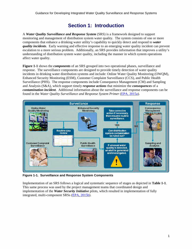
Figure 1-1 shows the components of an SRS grouped into two operational phases, surveillance and response. The surveillance components are designed to provide timely detection of water quality incidents in drinking water distribution systems and include: Online Water Quality Monitoring (OWQM), Enhanced Security Monitoring (ESM), Customer Complaint Surveillance (CCS), and Public Health Surveillance (PHS). The response components include Consequence Management (CM) and Sampling and Analysis (S&A), which support timely response actions that minimize the consequences of a contamination incident. Additional information about the surveillance and response components can be found in the Water Quality Surveillance and Response System Primer (EPA, 2015a).
Figure 1-1. Surveillance and Response System Components
Implementation of an SRS follows a logical and systematic sequence of stages as depicted in Table 1-1. This same process was used by the project management teams that coordinated design and implementation of the Water Security Initiative pilots, which resulted in implementation of fully integrated, multi-component SRSs (EPA, 2015b).

Guidance for Developing Integrated Water Quality Surveillance and Response Systems
2
Table 1-1. Stages of SRS Implementation Implementation Stage Description Preparation Establishing a project management team and a vision statement, defining
design goals and performance objectives, and identifying project constraints
Assessment Conducting an inventory of resources that could be leveraged for the SRS
Design Developing a workplan and specifications for each component
Installation Implementing the design and installing equipment
Preliminary operation Training utility and partner personnel on SRS operations and procedures, and collecting data to evaluate system performance
Real-time operation Operating the SRS to achieve the design goals, responding to alerts in real time, evaluating performance, and implementing enhancements
This document is intended for utilities and stakeholders that are planning to implement a multi-component SRS. It provides guidance on overarching activities necessary to design an integrated SRS including: project management, master planning, information management, alert investigation procedures, and training and exercises. Figure 1-2 shows how these activities relate to the stages of SRS implementation, noting that some activities occur only during certain stages of implementation.
Project management
Master planning
Information management
Alert investigation procedures
Training and exercises
Stages of SRS Implementation
Activities
Figure 1-2. Overarching Design Activities and the Stages of SRS Implementation
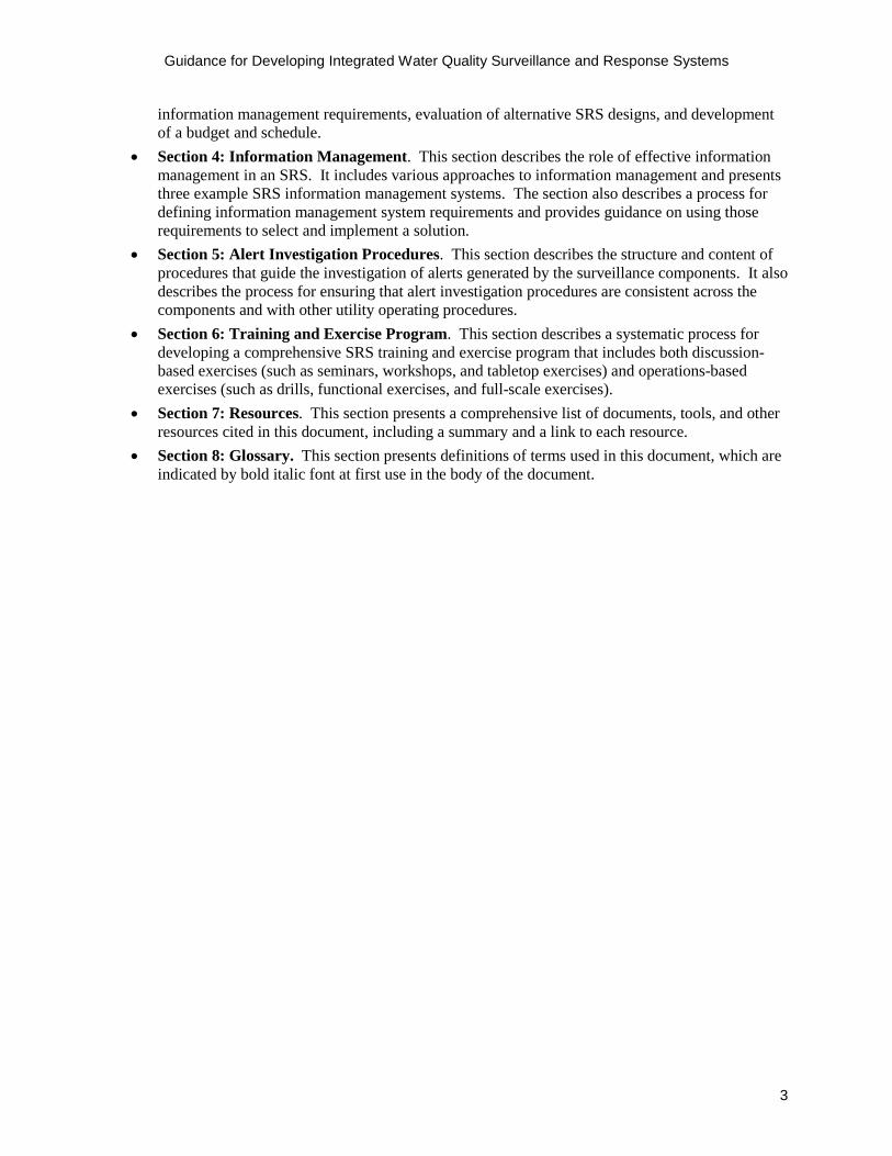
The remaining sections included in this document present guidance on each of the activities listed in Figure 1-2, as described below:
• Section 2: Project Management. This section describes the roles and responsibilities of theproject management team and component teams in designing and implementing a multi-component SRS.
• Section 3: Master Planning. This section discusses the master planning process for an SRSincluding development of design goals, performance objectives, and project constraints. It alsoprovides guidance on the review and consolidation of preliminary component designs and
Guidance for Developing Integrated Water Quality Surveillance and Response Systems
3
information management requirements, evaluation of alternative SRS designs, and development of a budget and schedule.
• Section 4: Information Management. This section describes the role of effective informationmanagement in an SRS. It includes various approaches to information management and presentsthree example SRS information management systems. The section also describes a process fordefining information management system requirements and provides guidance on using thoserequirements to select and implement a solution.
• Section 5: Alert Investigation Procedures. This section describes the structure and content ofprocedures that guide the investigation of alerts generated by the surveillance components. It alsodescribes the process for ensuring that alert investigation procedures are consistent across thecomponents and with other utility operating procedures.
• Section 6: Training and Exercise Program. This section describes a systematic process fordeveloping a comprehensive SRS training and exercise program that includes both discussion-based exercises (such as seminars, workshops, and tabletop exercises) and operations-basedexercises (such as drills, functional exercises, and full-scale exercises).
• Section 7: Resources. This section presents a comprehensive list of documents, tools, and otherresources cited in this document, including a summary and a link to each resource.
• Section 8: Glossary. This section presents definitions of terms used in this document, which areindicated by bold italic font at first use in the body of the document.

Guidance for Developing Integrated Water Quality Surveillance and Response Systems
4
Section 2: Project Management Design and implementation of an SRS is a cross-divisional effort that requires strong and effective project management. Project management for an SRS differs from other common utility projects with respect to the scope of involvement from divisions across a utility. Typical utility projects, such as distribution system expansion projects or process monitoring equipment installation, may only require coordination among a few divisions; however, design and implementation of a multi-component SRS will involve most utility divisions, including operations, engineering, water quality, security, information technology (IT), and customer service. Furthermore, partners outside of the utility such as public health partners, emergency response agencies, and state primacy agencies may play a role in the project as well. To coordinate the efforts of these participants, a project team should be established prior to beginning work on the design of an SRS or any of its components. The project team may include a project management team and component teams.
The project management team is responsible for overseeing all project activities, tracking the overall budget, and ensuring system integration. Component teams are composed of utility personnel and external partners with relevant technical expertise who design and implement specific SRS components (see Section 2.2 for a matrix of utility and partner positions and the components they may support). When forming component teams, utilities should consider assigning a component lead with technical expertise in the component focus area to guide the development of workplans, design specifications, and information management requirements. While project management and component teams will each have dedicated responsibilities, close coordination will be required for certain aspects of system design and implementation such as budget and personnel management, coordination with external partners, and design of information management and source data systems, as illustrated in Figure 2-1.
HELPFUL HINT Utilities should establish an SRS project management structure in line with the scale and complexity of their planned SRS. • A 1-2 component SRS can be
supported by a single project management team
• A ≥ 3 component SRS will likelyrequire a project managementteam and component teams

Guidance for Developing Integrated Water Quality Surveillance and Response Systems
5
ProjectManagement TeamMaster PlanCapital BudgetOverall Schedule
ComponentTeams
Component WorkplansComponent Budget
Component Schedule
Information Management
System
Use of Outside Consultants
Contracting and Procurement
Vehicle
Coordination with External
Partners
Source Data Systems
Personnel Availability and
Capability
Figure 2-1. Areas of Coordination between Project Management and Component Teams
2.1 Project Management Team For a utility planning to implement a multi-component SRS, the primary purpose of establishing a project management team is to provide oversight of the overall SRS design and implementation process. It is critical from the outset of the project that this team is granted the authority to reach consensus on issues related to the overall project budget and schedule and govern the project accordingly. The utility should select an experienced project manager with adequate availability to serve as the SRS Manager and lead the project management team.
The project management team will need sufficient administrative support to successfully design and implement a multi-component SRS given the scale and complexity of the project. It may be useful to leverage administrative support from within the utility to support meetings, document control, contracts, and procurements for the SRS.
ATTRIBUTES OF AN EFFECTIVESRS MANAGER
□ Project manager with experience in developingproject schedules, budgets, and project controls, and identifying support personnel
□ Acts as a project “champion” who believes in thevision and goals of the SRS
□ Demonstrates strong leadership and communicationskills to facilitate collaboration across utility divisions
□ Has the ability to gain buy-in from senior utilitymanagement and the board of directors
□ Commands the respect and support of the projectmanagement team and the component teams
□ Inspires utility personnel and partners to move theproject forward
□ Anticipates potential challenges that may ariseduring design and implementation and identifiescreative solutions
Guidance for Developing Integrated Water Quality Surveillance and Response Systems
6
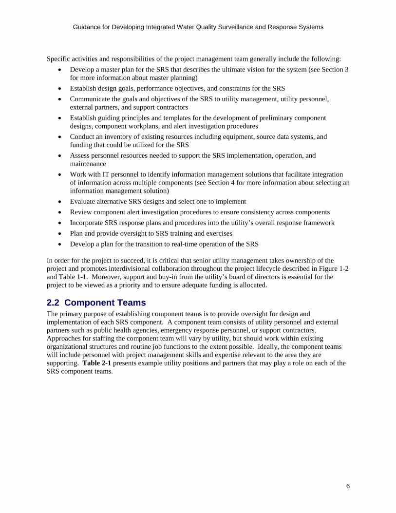
Specific activities and responsibilities of the project management team generally include the following: • Develop a master plan for the SRS that describes the ultimate vision for the system (see Section 3
for more information about master planning)• Establish design goals, performance objectives, and constraints for the SRS• Communicate the goals and objectives of the SRS to utility management, utility personnel,
external partners, and support contractors• Establish guiding principles and templates for the development of preliminary component
designs, component workplans, and alert investigation procedures• Conduct an inventory of existing resources including equipment, source data systems, and
funding that could be utilized for the SRS• Assess personnel resources needed to support the SRS implementation, operation, and
maintenance• Work with IT personnel to identify information management solutions that facilitate integration
of information across multiple components (see Section 4 for more information about selecting aninformation management solution)
• Evaluate alternative SRS designs and select one to implement• Review component alert investigation procedures to ensure consistency across components• Incorporate SRS response plans and procedures into the utility’s overall response framework• Plan and provide oversight to SRS training and exercises• Develop a plan for the transition to real-time operation of the SRS
In order for the project to succeed, it is critical that senior utility management takes ownership of the project and promotes interdivisional collaboration throughout the project lifecycle described in Figure 1-2 and Table 1-1. Moreover, support and buy-in from the utility’s board of directors is essential for the project to be viewed as a priority and to ensure adequate funding is allocated.
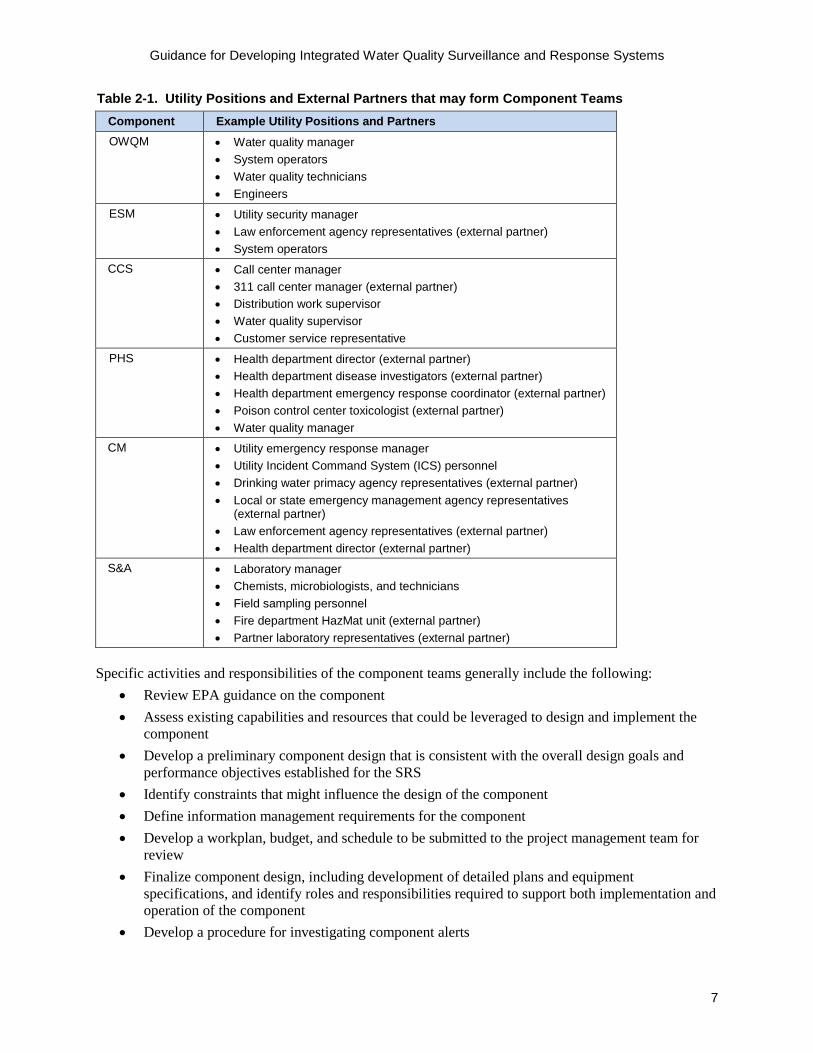
2.2 Component Teams The primary purpose of establishing component teams is to provide oversight for design and implementation of each SRS component. A component team consists of utility personnel and external partners such as public health agencies, emergency response personnel, or support contractors. Approaches for staffing the component team will vary by utility, but should work within existing organizational structures and routine job functions to the extent possible. Ideally, the component teams will include personnel with project management skills and expertise relevant to the area they are supporting. Table 2-1 presents example utility positions and partners that may play a role on each of the SRS component teams.
Guidance for Developing Integrated Water Quality Surveillance and Response Systems
7
Table 2-1. Utility Positions and External Partners that may form Component Teams Component Example Utility Positions and Partners OWQM • Water quality manager
• System operators• Water quality technicians• Engineers
ESM • Utility security manager• Law enforcement agency representatives (external partner)• System operators
CCS • Call center manager• 311 call center manager (external partner)• Distribution work supervisor• Water quality supervisor• Customer service representative
PHS • Health department director (external partner)• Health department disease investigators (external partner)• Health department emergency response coordinator (external partner)• Poison control center toxicologist (external partner)• Water quality manager
CM • Utility emergency response manager• Utility Incident Command System (ICS) personnel• Drinking water primacy agency representatives (external partner)• Local or state emergency management agency representatives
(external partner)• Law enforcement agency representatives (external partner)• Health department director (external partner)
S&A • Laboratory manager• Chemists, microbiologists, and technicians• Field sampling personnel• Fire department HazMat unit (external partner)• Partner laboratory representatives (external partner)
Specific activities and responsibilities of the component teams generally include the following: • Review EPA guidance on the component• Assess existing capabilities and resources that could be leveraged to design and implement the
component• Develop a preliminary component design that is consistent with the overall design goals and
performance objectives established for the SRS• Identify constraints that might influence the design of the component• Define information management requirements for the component• Develop a workplan, budget, and schedule to be submitted to the project management team for
review• Finalize component design, including development of detailed plans and equipment
specifications, and identify roles and responsibilities required to support both implementation andoperation of the component
• Develop a procedure for investigating component alerts
Guidance for Developing Integrated Water Quality Surveillance and Response Systems
8
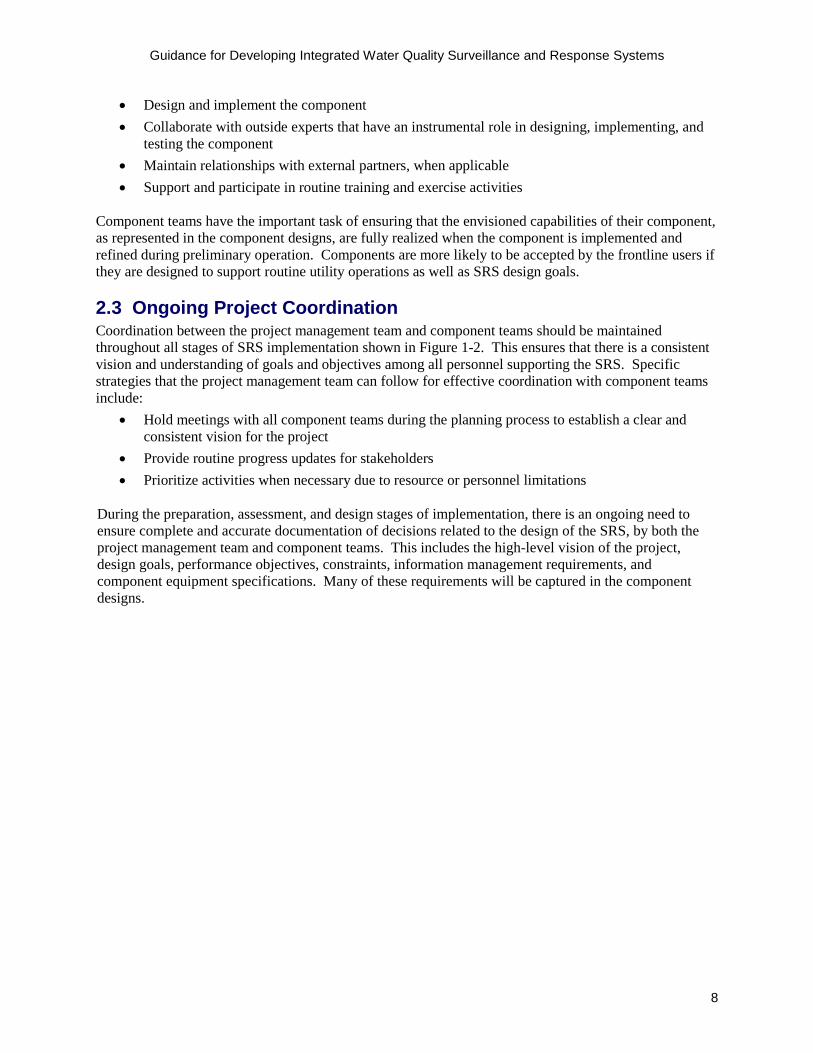
• Design and implement the component• Collaborate with outside experts that have an instrumental role in designing, implementing, and
testing the component• Maintain relationships with external partners, when applicable• Support and participate in routine training and exercise activities
Component teams have the important task of ensuring that the envisioned capabilities of their component, as represented in the component designs, are fully realized when the component is implemented and refined during preliminary operation. Components are more likely to be accepted by the frontline users if they are designed to support routine utility operations as well as SRS design goals.
2.3 Ongoing Project Coordination Coordination between the project management team and component teams should be maintained throughout all stages of SRS implementation shown in Figure 1-2. This ensures that there is a consistent vision and understanding of goals and objectives among all personnel supporting the SRS. Specific strategies that the project management team can follow for effective coordination with component teams include:
• Hold meetings with all component teams during the planning process to establish a clear andconsistent vision for the project
• Provide routine progress updates for stakeholders• Prioritize activities when necessary due to resource or personnel limitations
During the preparation, assessment, and design stages of implementation, there is an ongoing need to ensure complete and accurate documentation of decisions related to the design of the SRS, by both the project management team and component teams. This includes the high-level vision of the project, design goals, performance objectives, constraints, information management requirements, and component equipment specifications. Many of these requirements will be captured in the component designs.
Guidance for Developing Integrated Water Quality Surveillance and Response Systems
9
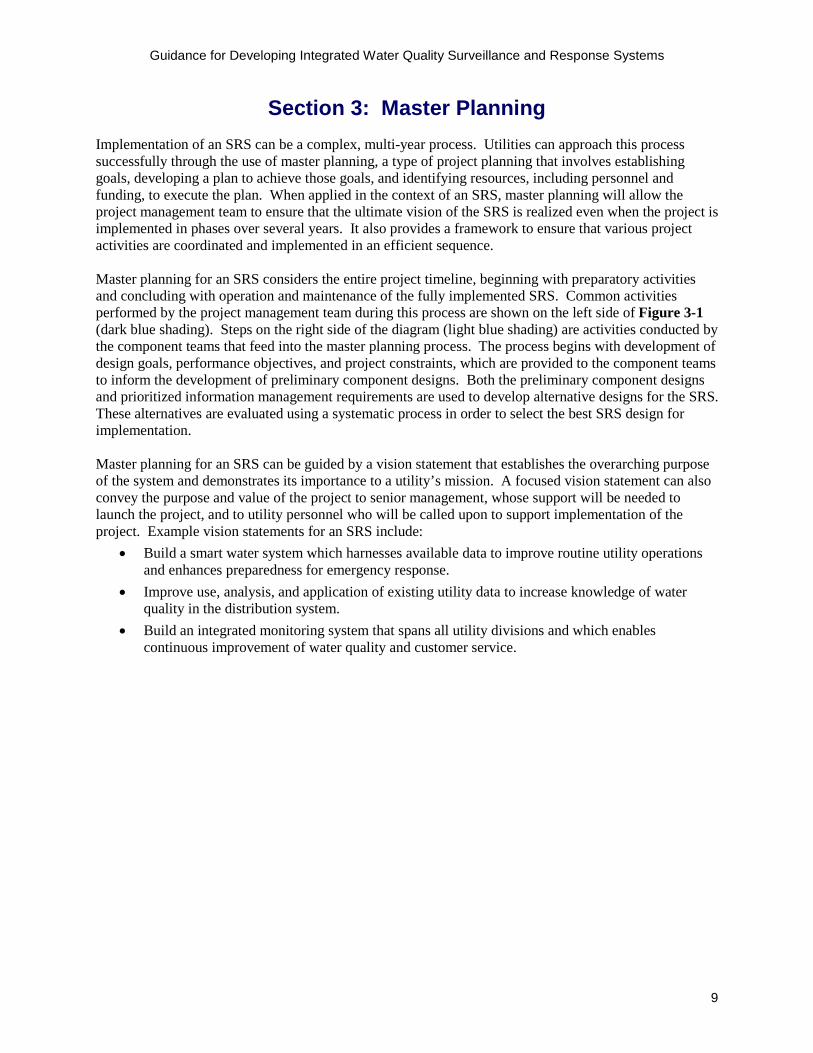
Section 3: Master Planning Implementation of an SRS can be a complex, multi-year process. Utilities can approach this process successfully through the use of master planning, a type of project planning that involves establishing goals, developing a plan to achieve those goals, and identifying resources, including personnel and funding, to execute the plan. When applied in the context of an SRS, master planning will allow the project management team to ensure that the ultimate vision of the SRS is realized even when the project is implemented in phases over several years. It also provides a framework to ensure that various project activities are coordinated and implemented in an efficient sequence.
Master planning for an SRS considers the entire project timeline, beginning with preparatory activities and concluding with operation and maintenance of the fully implemented SRS. Common activities performed by the project management team during this process are shown on the left side of Figure 3-1 (dark blue shading). Steps on the right side of the diagram (light blue shading) are activities conducted by the component teams that feed into the master planning process. The process begins with development of design goals, performance objectives, and project constraints, which are provided to the component teams to inform the development of preliminary component designs. Both the preliminary component designs and prioritized information management requirements are used to develop alternative designs for the SRS. These alternatives are evaluated using a systematic process in order to select the best SRS design for implementation.
Master planning for an SRS can be guided by a vision statement that establishes the overarching purpose of the system and demonstrates its importance to a utility’s mission. A focused vision statement can also convey the purpose and value of the project to senior management, whose support will be needed to launch the project, and to utility personnel who will be called upon to support implementation of the project. Example vision statements for an SRS include:
• Build a smart water system which harnesses available data to improve routine utility operationsand enhances preparedness for emergency response.
• Improve use, analysis, and application of existing utility data to increase knowledge of waterquality in the distribution system.
• Build an integrated monitoring system that spans all utility divisions and which enablescontinuous improvement of water quality and customer service.

Guidance for Developing Integrated Water Quality Surveillance and Response Systems
10
Establish design goals and performance objectives
Identify project constraints
Review preliminary component designs
Consolidate and prioritize information management requirements
Evaluate alternative SRS designs and select one to implement
Establish a project budget and schedule
Develop preliminary component designs
Define component information management requirements
Figure 3-1. Overview of the Master Planning Process
Sections 3.1 through 3.6 align with the steps of master planning shown on the left side of Figure 3-1, which represent project management team activities. Additionally, Appendix A provides a general template for developing an SRS master plan. Aspects of master planning specific to information management are covered in Section 4.4.
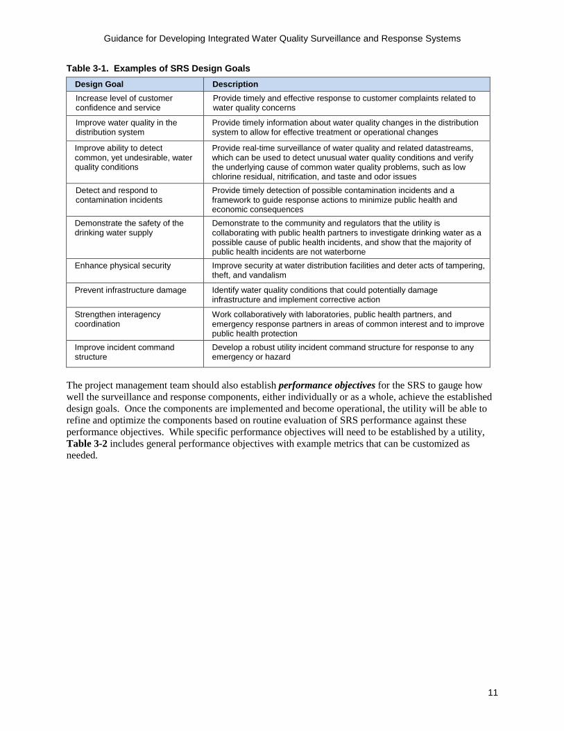
3.1 Establish Design Goals and Performance Objectives The first step of SRS master planning involves establishing design goals and performance objectives. Design goals define the specific benefits that a utility would like to realize through implementation and operation of an SRS. Several example design goals are described in Table 3-1. While all of these design goals can be achieved through implementation of a multi-component SRS, it is important for a utility to precisely define specific design goals that reflect their broader objectives for distribution system surveillance, operation, and response. Furthermore, not all design goals are equally important, and they should be prioritized according to a specific utility’s needs. Design goals that are clearly described and prioritized can also serve as a basis for evaluating alternative SRS designs, as discussed below.
Guidance for Developing Integrated Water Quality Surveillance and Response Systems
11
Table 3-1. Examples of SRS Design Goals Design Goal Description Increase level of customer confidence and service
Provide timely and effective response to customer complaints related to water quality concerns
Improve water quality in the distribution system
Provide timely information about water quality changes in the distribution system to allow for effective treatment or operational changes
Improve ability to detect common, yet undesirable, water quality conditions
Provide real-time surveillance of water quality and related datastreams, which can be used to detect unusual water quality conditions and verify the underlying cause of common water quality problems, such as low chlorine residual, nitrification, and taste and odor issues
Detect and respond to contamination incidents
Provide timely detection of possible contamination incidents and a framework to guide response actions to minimize public health and economic consequences
Demonstrate the safety of the drinking water supply
Demonstrate to the community and regulators that the utility is collaborating with public health partners to investigate drinking water as a possible cause of public health incidents, and show that the majority of public health incidents are not waterborne
Enhance physical security Improve security at water distribution facilities and deter acts of tampering, theft, and vandalism
Prevent infrastructure damage Identify water quality conditions that could potentially damage infrastructure and implement corrective action
Strengthen interagency coordination
Work collaboratively with laboratories, public health partners, and emergency response partners in areas of common interest and to improve public health protection
Improve incident command structure
Develop a robust utility incident command structure for response to any emergency or hazard
The project management team should also establish performance objectives for the SRS to gauge how well the surveillance and response components, either individually or as a whole, achieve the established design goals. Once the components are implemented and become operational, the utility will be able to refine and optimize the components based on routine evaluation of SRS performance against these performance objectives. While specific performance objectives will need to be established by a utility, Table 3-2 includes general performance objectives with example metrics that can be customized as needed.

Guidance for Developing Integrated Water Quality Surveillance and Response Systems
12
Table 3-2. Examples of SRS Performance Objectives
Performance Objective Description Example Metric
Incident coverage The type of incidents that can be detected by an SRS, including those resulting from natural, accidental, or intentional contamination
Number of water quality incidents detected
Spatial coverage The area monitored by an SRS % of utility distribution system monitored
Timeliness of detection and response
The amount of time between the start of a water quality incident and detection by an SRS component, and the amount of time between detection and implementation of response actions to minimize the consequences of the incident
Time to implement response actions, such as public notification, following identification of credible contamination (hours)
Operational reliability The likelihood the SRS is available and producing data of sufficient quality and quantity to reliably detect water quality incidents
% of time the SRS is available
Alert occurrence The relative frequency of valid and invalid alerts Number of invalid alerts month
per
Sustainability The degree to which the benefits derived from the SRS justify the cost to implement and maintain the system
List of specific benefits realized through operation of the SRS
3.2 Identify Project Constraints The next step of master planning involves identifying and documenting project constraints, such as:
Project capital budget: the total budget available for significant expenditures associated with
SRS implementation. Examples of such expenditures include security monitoring and
communication equipment, online water quality sensors, construction and installation costs, field
and laboratory testing instrumentation, and software and hardware for information management.
Annual operating and maintenance budget: the amount of funding available on an annual basis
to operate and maintain the SRS. When evaluating the available budget against the cost to
maintain the system, consideration should be given to all potential cost areas, including
equipment maintenance, alert investigations, training and exercises, annual license fees for
software, product support from vendors, and fees for communications services.
Availability of essential personnel: the time that personnel are available to operate and maintain
the SRS. When evaluating staff availability against project requirements, consideration should be
given to whether existing personnel will be trained to support selected SRS component operations
and maintenance, or if new personnel will be hired to support the SRS.
Policy restrictions: any utility-wide policies that limit or bound the design of the SRS, such as IT
restrictions, city or county building regulations, and contractual requirements. Examples of such
restrictions include policies that limit remote access to utility IT systems, or building codes that
would prohibit the installation of SRS-related monitoring equipment at certain locations in a city
(e.g., prohibition against the installation of equipment in a public right-of-way).
The project management team should review the considerations listed above to identify project
constraints. During the evaluation of alternatives, SRS designs that do not meet project constraints can be
eliminated from consideration, allowing the project management team to focus their efforts on viable
alternatives.
The design goals, performance objectives, and project constraints, described above in Sections 3.1 and
3.2, should be provided to the component teams when they begin to prepare preliminary component

Guidance for Developing Integrated Water Quality Surveillance and Response Systems
13
designs and define information management requirements. The overall project goals, objectives, and constraints serve two important functions: (1) define the scope and scale of the project, and (2) ensure that designs proposed by component teams are feasible and worth further consideration. Once the project management team has instructed the component teams to develop their preliminary component designs, there may be a delay of several months before the preliminary component designs are available for review by the project management team.
3.3 Review Preliminary Component Designs In this step of master planning, the project management team reviews the preliminary component designs submitted by each component team, which include the elements shown in the callout box below. Some component teams may provide several unique design options for review which vary by cost, complexity, and capability.
Several guidelines for eliminating options from consideration include preliminary component designs that:
• Do not adequately support the established designgoals and performance objectives
• Do not adhere to the established constraints• Rely on entities without a demonstrated capability to
support the SRS• Are not feasible to integrate into existing utility
operations
At the end of this step, the project management team should identify one or two preferred design options for each component, which can be used to develop alternative designs for the complete SRS. This information will be used in the evaluation of alternative SRS designs discussed in Section 3.5.
3.4 Consolidate and Prioritize Information Management Requirements The project management team should work with the IT design team to consolidate and prioritize information management requirements provided by the component teams. Reviewing and finalizing the requirements will allow the IT design team to gain an understanding of the functionality and features that end-users desire in the SRS information management system. This topic is discussed in further detail in Section 4.2.
The prioritized list of information management requirements should be used to conduct a preliminary assessment of potential information management solutions. Once a few viable solutions are identified, order of magnitude cost estimates should be developed for each. This information will be used in the evaluation of alternative SRS designs discussed in Section 3.5.
3.5 Evaluate SRS Design Alternatives and Select One to Implement In this step, the project management team develops SRS design alternatives based on the preliminary component designs selected for further consideration (see Section 3.3) and preliminary information management solutions (see Section 3.4). In some cases, a single SRS design may emerge as the obvious best choice. However, it is more likely that competing designs will emerge. SRS design alternatives may be developed from various permutations of the following:
ELEMENTS OF A PRELIMINARY COMPONENT DESIGN
• Preliminary information flow• Preliminary alert investigation
procedure• Personnel (availability and skill set)• Equipment options• Data analysis methods• Budget
o Capitalo Annual operations and
maintenance • Schedule
o Sequence of activitieso Duration of activitieso Key dependencies
Guidance for Developing Integrated Water Quality Surveillance and Response Systems
14
• Combining different components. For example, a utility may start with a design that includesCCS, CM, and S&A, and develop alternatives by adding PHS, OWQM, and ESM in variouscombinations.
• Combining different component designs. For example, OWQM designs using differentnumbers of monitoring stations or different sensor suites may be evaluated.
• Incorporating different information management solutions. For example, use of a relativelysimple information management system may conserve resources that can be used to implementadditional surveillance capabilities.
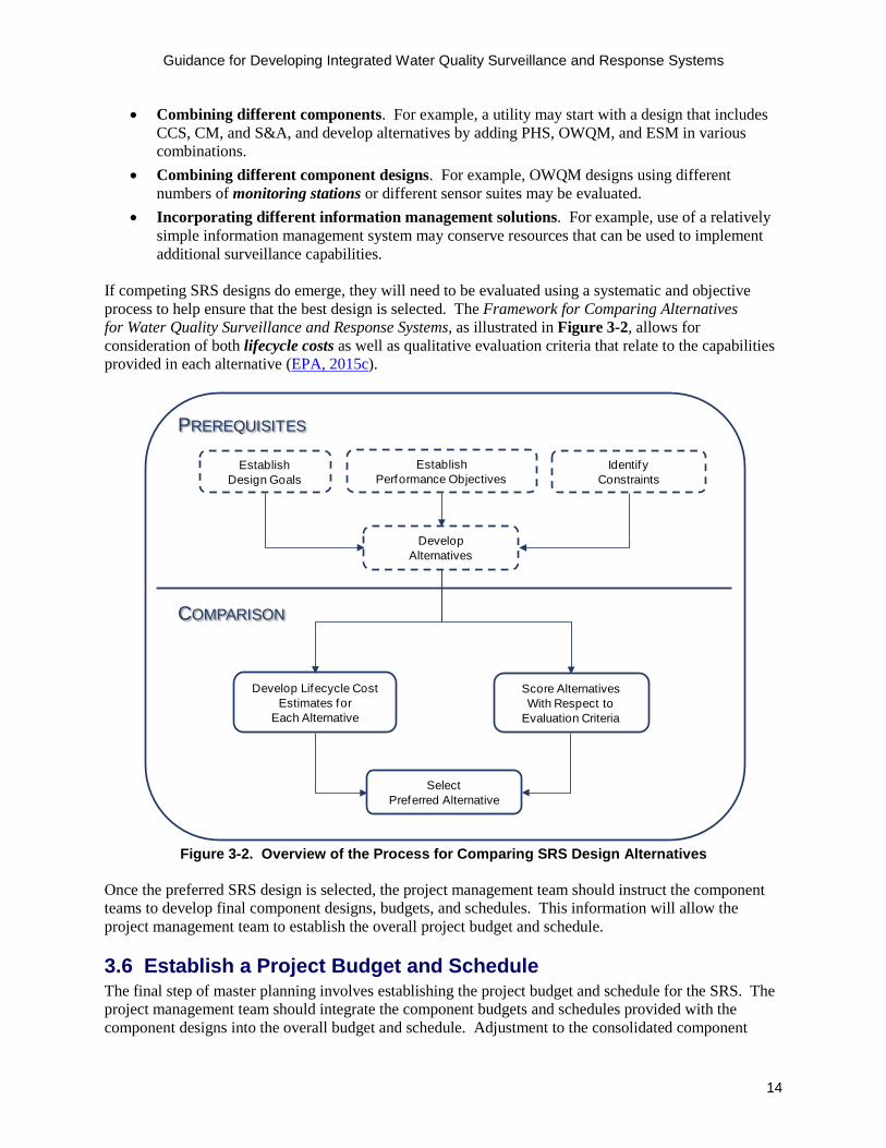
If competing SRS designs do emerge, they will need to be evaluated using a systematic and objective process to help ensure that the best design is selected. The Framework for Comparing Alternatives for Water Quality Surveillance and Response Systems, as illustrated in Figure 3-2, allows for consideration of both lifecycle costs as well as qualitative evaluation criteria that relate to the capabilities provided in each alternative (EPA, 2015c).
DevelopAlternatives
Develop Lifecycle Cost Estimates for
Each Alternative
Score AlternativesWith Respect to
Evaluation Criteria
SelectPreferred Alternative
EstablishPerformance Objectives
EstablishDesign Goals
IdentifyConstraints
PREREQUISITES
COMPARISON
Figure 3-2. Overview of the Process for Comparing SRS Design Alternatives
Once the preferred SRS design is selected, the project management team should instruct the component teams to develop final component designs, budgets, and schedules. This information will allow the project management team to establish the overall project budget and schedule.
3.6 Establish a Project Budget and Schedule The final step of master planning involves establishing the project budget and schedule for the SRS. The project management team should integrate the component budgets and schedules provided with the component designs into the overall budget and schedule. Adjustment to the consolidated component

Guidance for Developing Integrated Water Quality Surveillance and Response Systems
15
budgets and schedules will likely be necessary due to interdependencies among component implementation activities and final allocation of the available budget and other resources.
In addition to implementation costs, the project management team needs to account for the funding required for ongoing operation and maintenance of the SRS. Annual operations and maintenance costs provided with the preliminary component designs will be a large percentage of the annual expenses for the SRS. Additionally, there may be ongoing costs for the SRS that are not attributable to any single component, such as information management (see Section 4.3.3 for cost considerations related to selecting an information management solution), that should be considered when estimating an annual operations and maintenance budget for the SRS.
Given the amount of work associated with designing and implementing a complex system that involves multiple utility departments and external partners, most SRS projects will be phased and involve a project timeline of several years from initial preparations to the time when the system is fully operational. Based on this fact, it is important for the project management team to establish a logical sequence for significant implementation activities, particularly those that impact multiple components. Phased implementation may also eliminate or minimize certain project constraints, such as budget and personnel limitations. For example, installation of OWQM stations in phases over several years might allow a utility to build up to their desired number of monitoring locations while working within constraints on the annual capital budget available for this type of equipment. Consideration of these budget and scheduling constraints, along with the flexibility offered by phased implementation, will help the project management team to develop an overarching implementation plan that is achievable and efficient.
Adequate time should be built into the schedule to allow the components to pilot new equipment before making a decision about the final type, configuration, and installation location of equipment. Similarly, time should be allotted for preliminary operation of the system once all equipment and IT systems are operational. As noted earlier, the budget and schedule portion of the master plan may require updates to reflect changes in project status and expenditures as the system is implemented.
Budget constraints are often one of the more significant hurdles to implementation of any project. The callout box below provides information about potential funding opportunities for SRS implementation. Utilities will need to access the links provided below to learn more about the specific repayment terms of the loans described.
REMINDER Ensure that the schedule and availability of contractors, vendors, and external partners is accommodated when planning for aspects of the project that require coordination with outside entities.

Guidance for Developing Integrated Water Quality Surveillance and Response Systems
16
SRS FUNDING OPPORTUNITIES Pay-as-you-go: Funding an SRS project through pay-as-you-go involves incorporating the cost of implementation into the annual budget. This can occur through allocation of existing cash reserves or developing new sources of revenue measures such as capital improvement fees, increased property taxes, or tapping a portion of water sales revenue. This funding mechanism works best for a phased SRS implementation, where pieces of the system are gradually deployed as the capital becomes available.
Bonds/Loans: Funding an SRS project through bonds or loans incurs debt at the beginning of the project, which is typically paid back over a 10 or 20-year period. The debt may also be serviced through implementation of new sources of revenue such as capital improvement fees, increased property taxes, or a portion of water sales revenue. Financing the project using bonds or loans would allow for accelerated design and implementation of the project, with significant expenditures at the beginning of the project.
Grants/Federal Loans: Funding an SRS project through grants or federal loans involves applying to a government agency for funds at or below market interest rate loan. The project description should match the requirements of the agency providing the grant to improve the likelihood of an award. Discuss with the individual responsible for the grant review what the most important criteria are and other information that they will be considering during the review. The following organizations are potential sources of grant funding for an SRS project:
• Federal Emergency Management Agency Urban Agency Security Initiative: These funds are usually available to large metropolitan areas. Applications need to have a strong security focus, which is an excellent fit for the SRS project. (http://www.fema.gov/urban-areas-security-initiative-nonprofit-security-grant-program)
• Bureau of Reclamation: There are significant grant funding opportunities for systems that reduce the energy consumption, address climate risks, and support sustainability of water systems. SRS programs that have implemented protocols and technologies to aid in leak detection would score well for water and energy efficiency grants. (http://www.usbr.gov/watersmart/grants.html)
• Department of Agriculture: Districts that provide water to agricultural customers, along with urban customers, can apply for grants related to improving water quality and water availability for agricultural customers. The agricultural portion of water served by the utility should be a meaningful amount (at least 30 percent of deliveries). (http://www.rd.usda.gov/)
• Drinking Water State Revolving Fund: These federal loans must address a serious risk to public health, bring the systems into compliance with the Safe Drinking Water Act, consolidate water supplies, or replace aging infrastructure. Systems that have had primary standard violations that will be reduced or eliminated through the use of an SRS would score well for this type of grant.(http://yosemite.epa.gov/r10/water.nsf/drinking+water/state+revolving+fund)
Public-private partnership: Funding an SRS project through public-private partnerships involves working with a private entity that would benefit from financing some aspect of the SRS project. One simple example would be if a large water usage customer (e.g., a brewery) provided the site location and all or partial funding to place an OWQM station in their facility, with the utility maintaining the equipment and managing the data. The value of this partnership to the brewery would be access to water quality data that can be used to optimize their production process, while not holding responsibility for the cost of operating and maintaining the OWQM station. The benefit to the utility would be reduced upfront cost for the OWQM station as well as the ability to place the station in the distribution system at a non-utility facility. Another potential opportunity is a partnership with hospitals that would use the water quality data in a program to combat Legionella outbreaks.

Guidance for Developing Integrated Water Quality Surveillance and Response Systems
17
Section 4: Information Management A principle of SRS design is that concurrent monitoring of multiple datastreams increases the range of incidents that can be detected as well as the area of the distribution system monitored. However, unless data from the surveillance components (CCS, ESM, OWQM and PHS) can be effectively accessed and used in a timely manner, the benefits of a multi-component SRS cannot be fully realized. Thus, information management is a fundamental aspect of a successful SRS and encompasses methods and processes for capturing and storing data for both short- and long-term needs, and providing access to data in a usable format.
An SRS information management system refers to the combination of source data systems, tools, and processes that collectively support the SRS. It provides utility personnel with data needed to monitor real-time system conditions and to efficiently identify, investigate, and respond to water quality incidents or other undesirable changes in water quality, such as low residual disinfectant, rusty water, or taste and odor issues. While access to data from all relevant systems is essential, an SRS information management system does not have to involve complex visualization tools or complete integration of data into one system. Even simple solutions can yield significant improvements in a utility’s ability to manage and analyze data.
Section 4.1 describes approaches to information management and presents three example SRS information management systems. Section 4.2 describes a process for defining information management system requirements that utilities can employ to facilitate selection of a solution that will meet user needs. Section 4.3 provides guidance on using these requirements to select and implement a solution. Section 4.4 describes IT master planning for SRS information management systems.
4.1 Approaches to Information Management An SRS information management system can range from a fairly simple system with no automation to a sophisticated system with layers representing data from a variety of sources in an integrated, geospatial display. To illustrate the range of potential solutions, three general approaches to SRS information management are presented: (1) manual data access and analysis, (2) automation of information management functions, and (3) integration of information from multiple source data systems and automation of information management functions. Additionally, hybrid solutions may deploy a mix of manual and automated analysis approaches with different degrees of information integration.
4.1.1 Example of a Manual Information Management System Manual systems generally do not integrate data from multiple SRS components or ancillary source data systems into a single system. Rather, discrete source data systems must be accessed separately. In a manual system, data visualization and analysis capabilities are not included in a user interface but must be manually executed by a user, possibly using external tools such as Microsoft Excel. Data will typically need to be extracted from the source system and then manually loaded into a separate tool for further manipulation and display. Standardized procedures can be developed to guide execution of manual processes to perform routine data review and analysis.
Figure 4-1 provides an example of a simple, manual information management system that could support daily reviews of water quality customer complaints. In this example, the user exports customer complaint records from a call management system into an Excel workbook with button-activated macros that provide efficient data visualization through either a summary data table or time-series chart. The representation of water quality customer complaints allows the user to easily identify a spike in the number of customer complaints. In the figure, the background image shows a tabular listing of water

Guidance for Developing Integrated Water Quality Surveillance and Response Systems
18
quality complaints exported from the utility’s call management system. The images in the forefront show the summary table and time-series chart that would be created when the user clicks the macro buttons.
Figure 4-1. Manual System for Tracking Water Quality Customer Complaints
4.1.2 Example of an Automated Information Management System An automated information management system automates certain functions within existing or new source data systems that support the SRS, reducing the time and effort required to use the system. Automation can occur along a range of functions and systems. Simple examples of automation include code which automatically extracts data from a source data system at regular intervals, while a further enhancement could automate data analysis and alert notification functions. The combination of automated data extraction and analysis provides the capability for near-real time data analysis.

Guidance for Developing Integrated Water Quality Surveillance and Response Systems
19
Three information management functions that lend themselves to automation within an SRS information management system include data analysis and visualization, anomaly detection and alert notification, and geospatial display of alerts and related data.
Automated systems can significantly decrease the time required to access and analyze data. Other potential benefits, compared to a manual system, include:
• More timely anomaly detection due to continuous monitoring• A more intuitive system that is easier to use and thus requires less training• Fewer data transcription and data analysis errors• More consistent data evaluation due to automated workflows• Reduced effort required to gather information
Figure 4-2 shows screenshots from a system in which several information management functions have been automated for the CCS component. The background image is an example of an alert notification indicating a high volume of water quality customer complaints. The image in the forefront is an example plot that shows the location of the customer calls superimposed on the distribution system network map, which can be used to investigate potential spatial clustering of the calls. In contrast to the example depicted in Figure 4-1, the user is immediately notified of alerts, which are automatically generated through real-time data analysis. Also, investigation of alerts requires far less time and effort by the user as there is point-and-click functionality for viewing the data in meaningful formats.
UNIQUE APPROACH TO AUTOMATED ALERT NOTIFICATIONS
One of the Water Security Initiative pilot utilities implemented a complex, automated alerting function that included: • Different alerts depending on the shift• Escalation if acknowledgement is not
received within a pre-defined period• Notification through multiple
channels, such as text, voice, andemail
• Ability to respond to alert notificationsusing email or text

Guidance for Developing Integrated Water Quality Surveillance and Response Systems
20
Figure 4-2. Automated CCS Data Analysis, Alert Notification, and Data Display
4.1.3 Example of an Automated and Integrated Information Management System A fully automated and integrated information management system aggregates data from multiple utility source data systems that support the SRS into a centralized system with a single user interface, typically referred to as a dashboard, and displays the real-time status of multiple SRS components. Many of the crucial aspects of information management are automated, including data analysis and visualization, anomaly detection and alert notification, and geospatial display of alerts. An effective dashboard design can provide users with an overview of system status as well as detailed information about specific datastreams monitored through the SRS. Dashboard Design Guidance for Water Quality Surveillance and Response Systems provides additional information about the potential functionality, requirements, and design of a dashboard (EPA, 2015d).
SRS DASHBOARD FUNCTIONALITY Four of the Water Security Initiative pilot utilities developed SRS dashboards. Functionality that was implemented and found to be useful included: • Comprehensive view of system status with the
ability to drill down into detailed information • Spatial representation of alerts from all
surveillance components• Overlay of supplemental information, such as
work orders, on a GIS map• Event tracking, including the initial alert
investigation and follow-up activities

Guidance for Developing Integrated Water Quality Surveillance and Response Systems
21
Compared with example systems described in the two previous sections, development of a dashboard can be a significant undertaking involving substantial upfront capital costs and a considerable amount of collaboration among the component teams to ensure the single solution addresses the requirements of each component. However, this integrated display can allow for more effective and efficient distribution system monitoring and data analysis.
Figure 4-3 shows an example SRS dashboard in which recent CCS alert data, OWQM alert data, and grab sampling data is displayed geospatially. The telephone receiver icons indicate the location of water quality complaint calls associated with a CCS alert and the red circle with a water droplet shows the location of an OWQM station at which an alert has occurred. The triangular symbols indicate grab sampling locations: red indicates low chlorine values whereas green indicates chlorine values in an acceptable range.
Figure 4-3. Example SRS Dashboard
A dashboard enables utility personnel to better visualize and understand relationships among the datastreams. Data that is collected from discrete source data systems (such as in a water quality database or work management system) can often be viewed simultaneously on a geographic display to rapidly identify possible correlations, which is important as signals in the data indicative of water quality anomalies are expected to demonstrate spatial and temporal relationships. In the example SRS dashboard shown in Figure 4-3, the noticeable geographic clustering of the OWQM alert, CCS calls, and grab sampling locations with low chlorine values could immediately escalate the urgency of the alert investigation.
Another benefit of a dashboard is the efficiency that can be achieved by reducing the amount of time and effort required to gather relevant information during an alert investigation. In the previous examples, the

Guidance for Developing Integrated Water Quality Surveillance and Response Systems
22
user may have to log into separate systems or call other departments to acquire information that would be available through the dashboard.
4.2 Developing Information Management System Requirements This section describes a process for defining information management system requirements, which is recommended during development of any information management system, regardless of the level of complexity. This process ensures that the solution selected by the utility will have the necessary functionality and features for the intended system use and will be accepted by users. It is highly
recommended that utilities in the process of implementing an SRS form an IT design team composed of the individuals responsible for selecting, designing, and implementing the information management system that will support the SRS. The IT design team should facilitate the process of defining requirements, manage IT personnel responsible for building or procuring the SRS information management system, and interface with different utility departments or partner organizations that monitor external datastreams relevant to the SRS.
To begin designing the SRS information management system, the IT design team should engage all stakeholders, including utility personnel and external partners who will use the system, as well as IT personnel who will be responsible for implementing the system. External partners that play a role in the implementation of the information management system, such as a city IT department, local public health department, technology vendors, and communication service providers, should be engaged early. This builds relationships and buy-in necessary for a successful project and ensures that constraints and resource limitations are identified in the early stages of the project. This early engagement will also facilitate the process of defining and understanding one another’s roles and responsibilities for designing, implementing, and maintaining the SRS information management system as the project moves forward.
Oversight of SRS information management system implementation by a dedicated IT design team facilitates development of a comprehensive set of information management system requirements, development of a solution that meets those requirements, and sustained maintenance of the system. Two types of information management system requirements, which are described below, are defined during this process.
• Functional requirements: define key features and attributes of the system that are visible to theend user. Examples of functional requirements include the manner in which data can beaccessed, types of tables and plots that can be produced through the user interface, the method bywhich component alerts are transmitted to investigators, and the ability to generate customreports. Functional requirements will likely evolve throughout the requirements developmentprocess as the IT design team, IT personnel, and component teams collaborate to refine the needsof end users.
• Technical requirements: system attributes and design features that are often not readily apparentto the end user, but are essential to meeting functional requirements or other design constraints.Technical requirements include attributes such as system availability, information security andprivacy, back-up and recovery, data storage needs, and communication protocols. Theserequirements are generally developed by IT personnel.
There is often a relationship between a functional requirement and a technical requirement. For example, a functional requirement of the system might be the ability to display 13 months of historical water quality data. This functional requirement could lead to the development of a technical requirement that
HELPFUL HINT It is important to engage IT specialists at the beginning of the requirements development process and to maintain their involvement throughout design and implementation of the SRS information management system given that requirements will evolve over the life of the project.
Guidance for Developing Integrated Water Quality Surveillance and Response Systems
23
specifies the precise amount of data storage provided through the system to accommodate 13 months of data for all water quality monitoring locations.
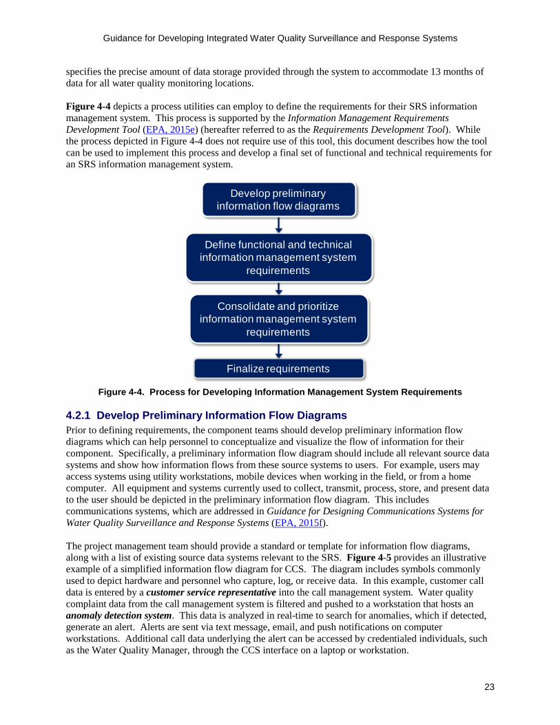
Figure 4-4 depicts a process utilities can employ to define the requirements for their SRS information management system. This process is supported by the Information Management Requirements Development Tool (EPA, 2015e) (hereafter referred to as the Requirements Development Tool). While the process depicted in Figure 4-4 does not require use of this tool, this document describes how the tool can be used to implement this process and develop a final set of functional and technical requirements for an SRS information management system.
Finalize requirements
Consolidate and prioritize information management system
requirements
Define functional and technical information management system
requirements
Develop preliminary information flow diagrams
Figure 4-4. Process for Developing Information Management System Requirements
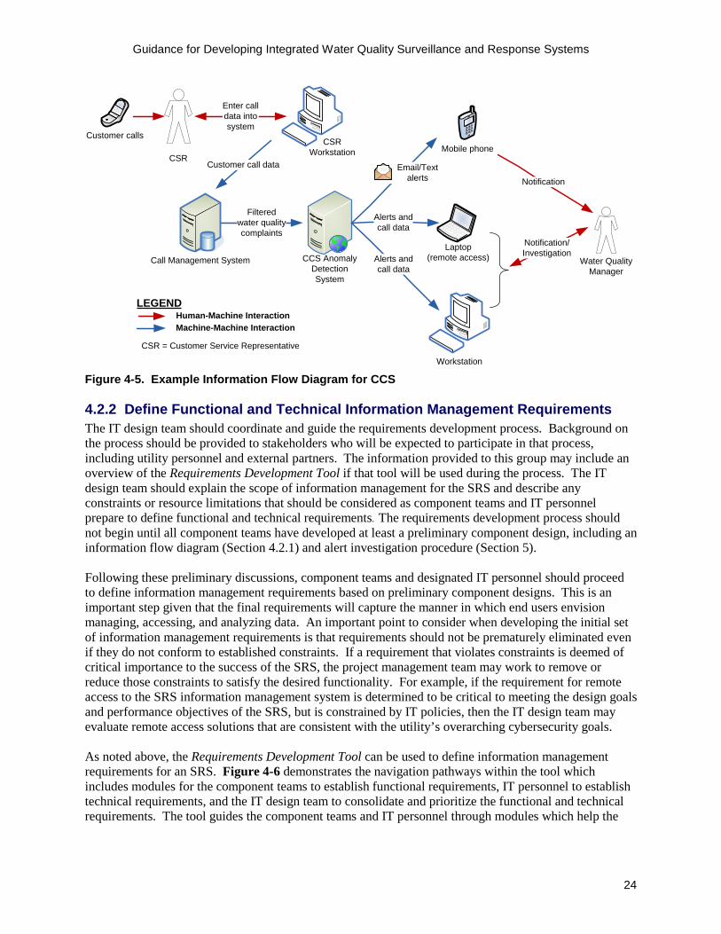
4.2.1 Develop Preliminary Information Flow Diagrams Prior to defining requirements, the component teams should develop preliminary information flow diagrams which can help personnel to conceptualize and visualize the flow of information for their component. Specifically, a preliminary information flow diagram should include all relevant source data systems and show how information flows from these source systems to users. For example, users may access systems using utility workstations, mobile devices when working in the field, or from a home computer. All equipment and systems currently used to collect, transmit, process, store, and present data to the user should be depicted in the preliminary information flow diagram. This includes communications systems, which are addressed in Guidance for Designing Communications Systems for Water Quality Surveillance and Response Systems (EPA, 2015f).
The project management team should provide a standard or template for information flow diagrams, along with a list of existing source data systems relevant to the SRS. Figure 4-5 provides an illustrative example of a simplified information flow diagram for CCS. The diagram includes symbols commonly used to depict hardware and personnel who capture, log, or receive data. In this example, customer call data is entered by a customer service representative into the call management system. Water quality complaint data from the call management system is filtered and pushed to a workstation that hosts an anomaly detection system. This data is analyzed in real-time to search for anomalies, which if detected, generate an alert. Alerts are sent via text message, email, and push notifications on computer workstations. Additional call data underlying the alert can be accessed by credentialed individuals, such as the Water Quality Manager, through the CCS interface on a laptop or workstation.
Guidance for Developing Integrated Water Quality Surveillance and Response Systems
24
Customer call data
Filtered water quality complaints
LEGEND
Machine-Machine InteractionHuman-Machine Interaction
CSR = Customer Service Representative
Customer calls
Call Management System
CSR
CSR Workstation
CCS Anomaly Detection System
Mobile phone
Workstation
Alerts and call data
Laptop (remote access)
Alerts and call data
Water Quality Manager
Email/Textalerts
Enter call data into system
Notification/Investigation
Notification
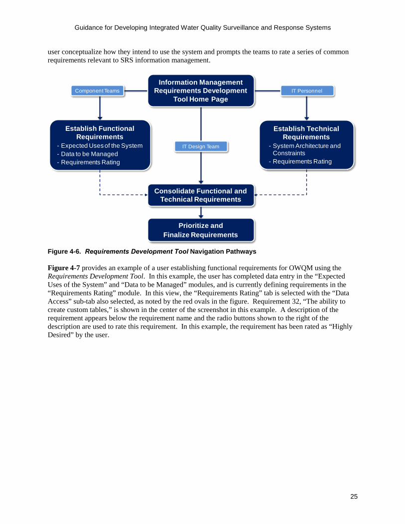
Figure 4-5. Example Information Flow Diagram for CCS 4.2.2 Define Functional and Technical Information Management Requirements The IT design team should coordinate and guide the requirements development process. Background on the process should be provided to stakeholders who will be expected to participate in that process, including utility personnel and external partners. The information provided to this group may include an overview of the Requirements Development Tool if that tool will be used during the process. The IT design team should explain the scope of information management for the SRS and describe any constraints or resource limitations that should be considered as component teams and IT personnel prepare to define functional and technical requirements. The requirements development process should not begin until all component teams have developed at least a preliminary component design, including an information flow diagram (Section 4.2.1) and alert investigation procedure (Section 5). Following these preliminary discussions, component teams and designated IT personnel should proceed to define information management requirements based on preliminary component designs. This is an important step given that the final requirements will capture the manner in which end users envision managing, accessing, and analyzing data. An important point to consider when developing the initial set of information management requirements is that requirements should not be prematurely eliminated even if they do not conform to established constraints. If a requirement that violates constraints is deemed of critical importance to the success of the SRS, the project management team may work to remove or reduce those constraints to satisfy the desired functionality. For example, if the requirement for remote access to the SRS information management system is determined to be critical to meeting the design goals and performance objectives of the SRS, but is constrained by IT policies, then the IT design team may evaluate remote access solutions that are consistent with the utility’s overarching cybersecurity goals. As noted above, the Requirements Development Tool can be used to define information management requirements for an SRS. Figure 4-6 demonstrates the navigation pathways within the tool which includes modules for the component teams to establish functional requirements, IT personnel to establish technical requirements, and the IT design team to consolidate and prioritize the functional and technical requirements. The tool guides the component teams and IT personnel through modules which help the
Guidance for Developing Integrated Water Quality Surveillance and Response Systems
25
user conceptualize how they intend to use the system and prompts the teams to rate a series of common requirements relevant to SRS information management.
Establish Functional Requirements
- Expected Uses of the System- Data to be Managed- Requirements Rating
Establish Technical Requirements
- System Architecture and Constraints
- Requirements Rating
Prioritize and Finalize Requirements
Consolidate Functional and Technical Requirements
Information Management Requirements Development
Tool Home PageComponent Teams IT Personnel
IT Design Team
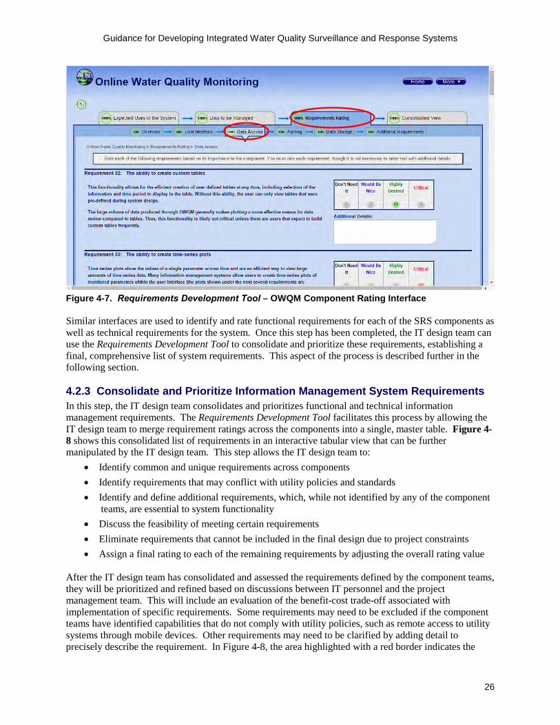
Figure 4-6. Requirements Development Tool Navigation Pathways Figure 4-7 provides an example of a user establishing functional requirements for OWQM using the Requirements Development Tool. In this example, the user has completed data entry in the “Expected Uses of the System” and “Data to be Managed” modules, and is currently defining requirements in the “Requirements Rating” module. In this view, the “Requirements Rating” tab is selected with the “Data Access” sub-tab also selected, as noted by the red ovals in the figure. Requirement 32, “The ability to create custom tables,” is shown in the center of the screenshot in this example. A description of the requirement appears below the requirement name and the radio buttons shown to the right of the description are used to rate this requirement. In this example, the requirement has been rated as “Highly Desired” by the user.
Guidance for Developing Integrated Water Quality Surveillance and Response Systems
26
Figure 4-7. Requirements Development Tool – OWQM Component Rating Interface
Similar interfaces are used to identify and rate functional requirements for each of the SRS components as well as technical requirements for the system. Once this step has been completed, the IT design team can use the Requirements Development Tool to consolidate and prioritize these requirements, establishing a final, comprehensive list of system requirements. This aspect of the process is described further in the following section.
4.2.3 Consolidate and Prioritize Information Management System Requirements In this step, the IT design team consolidates and prioritizes functional and technical information management requirements. The Requirements Development Tool facilitates this process by allowing the IT design team to merge requirement ratings across the components into a single, master table. Figure 4-8 shows this consolidated list of requirements in an interactive tabular view that can be further manipulated by the IT design team. This step allows the IT design team to:
• Identify common and unique requirements across components• Identify requirements that may conflict with utility policies and standards• Identify and define additional requirements, which, while not identified by any of the component
teams, are essential to system functionality• Discuss the feasibility of meeting certain requirements• Eliminate requirements that cannot be included in the final design due to project constraints• Assign a final rating to each of the remaining requirements by adjusting the overall rating value
After the IT design team has consolidated and assessed the requirements defined by the component teams, they will be prioritized and refined based on discussions between IT personnel and the project management team. This will include an evaluation of the benefit-cost trade-off associated with implementation of specific requirements. Some requirements may need to be excluded if the component teams have identified capabilities that do not comply with utility policies, such as remote access to utility systems through mobile devices. Other requirements may need to be clarified by adding detail to precisely describe the requirement. In Figure 4-8, the area highlighted with a red border indicates the

Guidance for Developing Integrated Water Quality Surveillance and Response Systems
27
fields in the interactive tabular view where the IT design team is able to adjust the final rating value for the functional and technical requirements.
Figure 4-8. Requirements Development Tool – IT Design Team Working View During the process of consolidating and prioritizing requirements, one or more physical architecture diagrams may be developed by the IT design team based on the consolidated component requirements and information flow diagrams. The initial versions of these architecture diagrams may be skeletonized versions of the final design that depict the physical elements of the system (e.g., source data systems, servers, databases, and interfaces). Furthermore, these architecture diagrams can support comparison of alternative designs of the information management system, with respect to criteria such as performance, cost, and complexity. Figure 4-9 presents an example physical architecture diagram for the CCS component of an SRS. In this example, the customer information is available in the call center database servers. These servers exist in their own security domain, separated by a firewall, and according to this example utility’s IT policies, cannot be accessed by any system outside of this security domain. Thus, to provide this data to the SRS information management system, it is pushed from the call center security domain to a secure FTP server every 15 minutes where the data poller can request it. The data can then be loaded to the operational data store on a regular interval to synchronize with the new data from the call center application servers.

Guidance for Developing Integrated Water Quality Surveillance and Response Systems
28
Figure 4-9. Example of a CCS Physical Architecture Diagram
4.2.4 Finalize Requirements In this step, the IT design team should document the final set of requirements. The Requirements Development Tool has a feature that allows users to produce an output file that contains the final list of functional and technical requirements as selected and rated by the IT design team. This list can then be used to guide the design or procurement of the SRS information management system. Clear and thorough
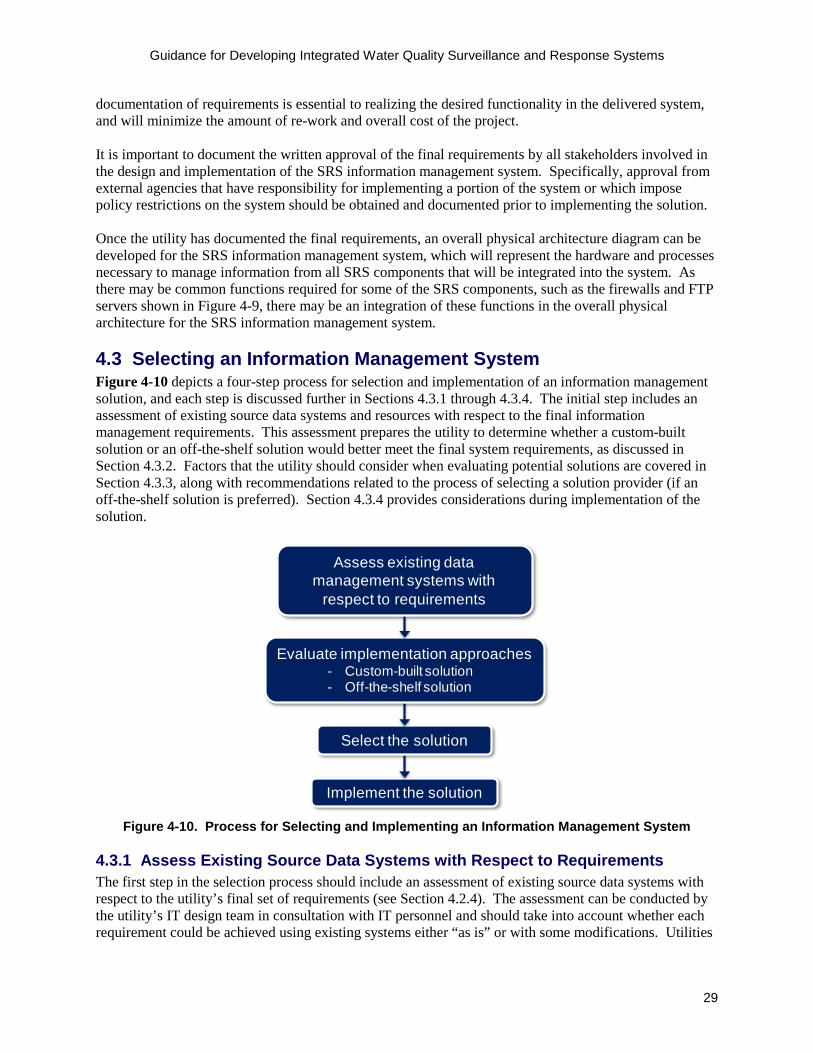
Guidance for Developing Integrated Water Quality Surveillance and Response Systems
29
documentation of requirements is essential to realizing the desired functionality in the delivered system, and will minimize the amount of re-work and overall cost of the project.
It is important to document the written approval of the final requirements by all stakeholders involved in the design and implementation of the SRS information management system. Specifically, approval from external agencies that have responsibility for implementing a portion of the system or which impose policy restrictions on the system should be obtained and documented prior to implementing the solution.
Once the utility has documented the final requirements, an overall physical architecture diagram can be developed for the SRS information management system, which will represent the hardware and processes necessary to manage information from all SRS components that will be integrated into the system. As there may be common functions required for some of the SRS components, such as the firewalls and FTP servers shown in Figure 4-9, there may be an integration of these functions in the overall physical architecture for the SRS information management system.
4.3 Selecting an Information Management System Figure 4-10 depicts a four-step process for selection and implementation of an information management solution, and each step is discussed further in Sections 4.3.1 through 4.3.4. The initial step includes an assessment of existing source data systems and resources with respect to the final information management requirements. This assessment prepares the utility to determine whether a custom-built solution or an off-the-shelf solution would better meet the final system requirements, as discussed in Section 4.3.2. Factors that the utility should consider when evaluating potential solutions are covered in Section 4.3.3, along with recommendations related to the process of selecting a solution provider (if an off-the-shelf solution is preferred). Section 4.3.4 provides considerations during implementation of the solution.
Implement the solution
Select the solution
Evaluate implementation approaches- Custom-built solution- Off-the-shelf solution
Assess existing data management systems with
respect to requirements
Figure 4-10. Process for Selecting and Implementing an Information Management System
4.3.1 Assess Existing Source Data Systems with Respect to Requirements The first step in the selection process should include an assessment of existing source data systems with respect to the utility’s final set of requirements (see Section 4.2.4). The assessment can be conducted by the utility’s IT design team in consultation with IT personnel and should take into account whether each requirement could be achieved using existing systems either “as is” or with some modifications. Utilities

Guidance for Developing Integrated Water Quality Surveillance and Response Systems
30
that have elected to use the Requirements Development Tool to define requirements can refer to the component data entered in the “Data to be Managed” module as component teams were prompted to indicate existing systems that could be leveraged. Examples of existing source data systems that might be used for SRS information management include:
• Call management system. Manages customer calls received by the utility and may includefunctionality to classify and direct calls.
• Work management system. Contains information related to work activities in the distributionsystem, including work orders and work requests.
• Supervisory Control and Data Acquisition (SCADA). Collects, displays and stores operationaldata from treatment plants, pumping facilities, and other monitoring points throughout thetreatment plant and distribution system.
• Geographic Information System (GIS). Collects, manages, analyzes, and displaysgeographically referenced information.
• Laboratory Information Management System (LIMS). Contains detailed analytical resultsand related information for water samples analyzed in-house or by external laboratories.
• Water quality database. Repository for routinely monitored water quality data that may not becaptured in a LIMS or SCADA including results associated with field investigations, such asthose resulting from customer water quality complaints.
• External systems (such as PHS systems). Collects and analyzes information relevant to theSRS, such as health-related data monitoring systems that identify anomalies indicative of unusualincidence of disease.
• Business enterprise systems. Large-scale software application that support business processes,information flows, reporting, and data analysis. This may include customer billing systems, assetmanagement systems, and email systems.
Utilities should also conduct an inventory of IT infrastructure, including the internal network (wiring, switches and Wi-Fi), external data connections (T1, TLS 4G LTE), and secure access (VPN or Citrix gateway).
This initial assessment should also evaluate the level of effort required to update existing systems (if needed) to meet SRS information management requirements, which will depend largely on the functionality available in the existing system. These requirements should be compared to the utility’s in-house capabilities, including experience level and availability of IT personnel, which would be needed to modify existing systems to meet the final set of requirements.
4.3.2 Evaluate Implementation Approaches This section discusses two general implementation approaches for meeting the SRS information management system requirements: developing a custom-built solution or implementing an off-the-shelf solution. A custom-built solution could either be developed by utility IT personnel or a hired contractor, whereas an off-the-shelf solution would be purchased from a commercial software vendor. The IT design team can evaluate which of these approaches would best achieve the final system requirements. In some cases, a hybrid approach using customization of existing systems and procurement of new hardware or software may be appropriate.
Develop a Custom-built Solution One option for meeting SRS information management system requirements is to develop a custom-built solution by leveraging features or functionality of existing systems. Custom-built solutions can be simple or complex, depending on the utility’s final set of requirements and available resources. One example of

Guidance for Developing Integrated Water Quality Surveillance and Response Systems
31
a relatively simple custom-built solution is to use existing functionality in a SCADA system to establish a setpoint alert for OWQM. Utilization of functionality in existing source data systems can be a low-cost solution to enhancing SRS capabilities.
A slightly more advanced custom-built solution could involve implementation of data transfer protocols to send data between existing systems. For example, establishing a schedule for the automated transfer of records from a work order system to a GIS system. A utility with experienced IT personnel may be able to implement a customized solution or, in the absence of in-house IT expertise, employ contractor support to build and maintain the system.
If there is high priority functionality in the final set of requirements that could not be met by existing systems, the utility may opt to develop a new custom-built solution, which would likely be a more complex and potentially significant undertaking in comparison to the example solutions described above. For example, an SRS dashboard could be built on top of existing source data systems to provide data access and analysis capabilities for those systems through a common interface.
A custom-built solution can offer significant benefits, including the convenience of onsite IT personnel, with extensive knowledge of the solution. The utility can build features to meet unique requirements that may not be available in commercial products. Moreover, a custom-built solution allows the utility to maintain control of the system design and to modify the system when requirements evolve.
One drawback to this approach is the lack of external support from a vendor for troubleshooting and system maintenance. Thus, if the developer of the custom-built solution is unavailable (such as through personnel turnover), routine maintenance and updates may not be addressed and it may require significant effort for someone new to learn and maintain the system. To avoid the potential for an unsupported system, the utility should maintain comprehensive documentation of system design and maintenance procedures and ensure that multiple utility IT personnel (or contractor support personnel) are trained on these procedures. Additionally, if the solution is built by a contractor, thorough documentation and training can mitigate the dependency on continued support from the contractor, lowering the overall cost to maintain the system.
Custom-built solutions should only be considered if skilled personnel are available to do the work and if utility management is willing to support ongoing maintenance. Without management buy-in, maintenance of a custom-built solution can be neglected, resulting in deteriorating performance and decreased attention to the SRS by the users. In the absence of this commitment, an off-the-shelf solution with vendor support is likely the more sustainable option.
Implement an Off-the-shelf Solution Another option for implementing an SRS information management system is to procure an off-the-shelf solution. There are a wide range of commercially available products that provide data management, access, and visualization functionality for time-series data. For example, Qlik Sense, Microsoft Power BI, iDashboards, and WISKI are products currently used within the Water Sector to manage and visualize utility data.
Off-the-shelf solutions are often the more practical option for utilities without the technical personnel to build their own solutions. Costs for the product, ancillary hardware and software, and vendor support vary but may be reasonable when compared to the level of effort that would be required to build and
HELPFUL HINT While a number of sophisticated anomaly detection systems are available, thresholds or setpoints can provide anomaly detection and are simple and inexpensive to implement. Setpoints are intuitive and readily interpreted by trained personnel (Umberg and Allgeier, 2016).

Guidance for Developing Integrated Water Quality Surveillance and Response Systems
32
maintain a custom solution. However, even with an off-the shelf solution, some customization by the solution provider may be necessary to configure the product within the utility’s existing infrastructure. A major benefit of off-the-shelf solutions is that these products are generally thoroughly tested, reliable, and regularly updated. New versions are periodically released to address issues such as security vulnerabilities identified by the solution provider. In addition, experienced support is generally available and thus the utility does not need to retain a group of experienced IT personnel within its organization. However, there are drawbacks to this approach, such as the fact that an off-the-shelf solution may not meet all of the desired functionality. Furthermore, the utility may need support from the solution provider for simple updates or modifications to the system. The cost and response time of vendor support for trouble-shooting issues with a product are often dictated by the terms of a service agreement, and preclude flexibility in the level of support provided. It is also important to operate the solution within vendor stipulated parameters to avoid violating the product warranty. Moreover, the sustainability of an off-the-shelf solution will rely extensively on the stability and longevity of the solution provider. Some of these drawbacks can be mitigated through vendor provided training on advanced functionality of the solution, which can provide the user with the knowledge necessary to maintain the product and alter the configuration as necessary. If it is determined that an off-the-shelf solution is the best approach, the preferred product can be selected through a competitive process wherein the final requirements can be used to define specifications in the request for proposals. Prior to developing a request for proposals, utilities should consider performing market research to identify potential solutions by conducting web searches or leveraging market research performed by IT advisory companies such as Gartner, International Data Corporation, or Forrester. This step will allow the utility to determine if any specifications beyond the final requirements should be included in the request for proposals. To evaluate multiple proposals submitted during a competitive process, the utility should also consider scheduling a product demonstration session with each solution provider under consideration, during which solution providers are requested to demonstrate a common suite of functions and features using a utility-provided dataset. This approach facilitates comparison of all solutions under consideration against the same set of requirements. The utility should involve relevant parties in evaluation and selection of the solution, including the IT design team, project management team, component teams, and frontline personnel. 4.3.3 Select the Solution A solution for the SRS information management system can be selected based on the final requirements, available resources, and the decision to implement a custom-built or off-the-shelf solution. Consideration of these factors will allow the IT design team, in consultation with the project management team, to identify one or more potential solutions. A list of items which should be documented and discussed by the team for each potential solution includes:
• Cost and level of effort required to implement and maintain the solution • Specialized skills or knowledge required to implement and maintain the solution • Prospect for reliable technical support over the life of the solution
FACTORS TO CONSIDER WHEN EVALUATING OFF-THE-SHELF TECHNOLOGIES
□ How well the solution meets final information management system requirements
□ Longevity and reputation of solution provider (request references)
□ Maturity of solution and extent of product’s use in the Water Sector
□ Availability of training on use of solution (consider whether in-person training is necessary or if self-guided training aids will suffice)
□ Cost structure for the product support including implementation, maintenance, and troubleshooting (e.g., fixed price versus cost per incident)
Guidance for Developing Integrated Water Quality Surveillance and Response Systems
33
• Ability of frontline users to understand and utilize the solution• Ability to incorporate new functionality in later phases of development• Additional hardware and software required to implement the solution• Compatibility of solution with existing systems
For a rigorous evaluation of potential solutions, the utility may consider employing the process described in the Framework for Comparing Alternatives for Water Quality Surveillance and Response Systems (EPA, 2015c) to determine which alternative best meets the information management requirements and provides the most value for the investment. The process described in this document considers both lifecycle costs and qualitative evaluation factors for ranking the alternatives.
4.3.4 Implement the Solution Before implementation begins, complete documentation of the final requirements and physical architecture should be provided to the developer who will be responsible for designing and implementing the SRS information management system. This could be utility IT personnel, utility contractors, or a vendor. The utility should anticipate that the implementation process will be iterative as requirements are further refined and as the functionality of the system is tested. Often, the developer provides the preliminary system design to users through screen mockups or development versions of the solution to verify that the requirements are properly translated into system design, and to further refine the desired functionality of the system. It is important that the IT design team notify the developer of IT protocols, policies, or standards that must be followed when implementing the solution.
4.4 IT Master Planning Given that implementation of an information management system for a multi-component SRS can be a complex, multi-year process, the IT design team can approach this process successfully through the use of IT master planning to define requirements and implement the solution. IT master planning for an SRS information management system should parallel the activities conducted during SRS master planning (Section 3) to ensure that design decisions related to the overall SRS and the selection of an information management system are closely coordinated between the project management team and the IT design team. IT master planning will also allow the utility to avoid development of duplicate systems through consideration of SRS requirements in relation to utility-wide or city-wide IT projects when projecting funding and resource needs. Some SRS information management system capabilities may be incorporated during regular lifecycle upgrades of existing systems, and therefore may involve minimal or no additional capital costs.
During system design, the IT design team should consider factors that may have both short-term and long-term implications, such as: (1) access privileges and security, (2) external hosting of data orsoftware, (3) system adaptability, and (4) system documentation.These topics are discussed below.
4.4.1 Access Privileges and Security Access to information generated by the surveillance components is a key requirement of an SRS information management system. However, the need for reliable access to information must be balanced with cybersecurity requirements. When integrating previously disparate source data systems within the utility, such as through implementation of a dashboard, new cybersecurity vulnerabilities can be inadvertently introduced. Early in the design phase, and on a continuing basis, the utility should identify
HELPFUL HINT The IT design team should determine whether any current source data systems which will be leveraged for the SRS information management system will be phased out or upgraded prior to implementing the solution.
Guidance for Developing Integrated Water Quality Surveillance and Response Systems
34
and address cybersecurity vulnerabilities associated with the system architecture, incoming and outgoing traffic, and access privileges. Information related to cybersecurity best practices for water systems can be found in the publication titled Process Control System Security Guidance for the Water Sector, and the associated Cybersecurity Tool applies information entered by the user to develop a set of utility-specific cybersecurity recommendations based on user input (AWWA, 2014). For each recommended control, the tool provides a reference to existing standards, which offer more detailed information about how to implement the control. In general, utilities should seek to minimize the number of system users and access points. While it is important that frontline personnel have access to the SRS information management system in order to investigate component alerts, these access points could expose sensitive utility data, such as utility infrastructure details or customer information, to unauthorized personnel. The utility will also need to determine whether remote access to SRS information management systems is necessary. Given that an important goal of an SRS is to achieve timely receipt of data to expedite investigation of water quality anomalies, utilities should consider strategies for investigators to access information remotely if they receive component alert notifications when away from their workstations. The amount of information that is available via remote access should be necessary and sufficient to initiate the investigation. Options for implementing remote access include pushing data from utility systems onto a web application, or through remote log-in to a data historian with security controls that prevent access to the primary information management system. 4.4.2 System Adaptability Given the likelihood that utilities will design and implement components of an SRS in phases as funding becomes available, the SRS information management system should be able to accommodate incremental design changes, such as the addition of new datastreams over time, or updates to external systems that interface with the SRS information management system. Additionally, SRS information management system implementation plans should reflect the priority placed on each requirement. Functions that are most important to the operation of the system should be implemented prior to those that have a lower priority. Furthermore, a robust system that provides users with the ability to easily adjust key parameters without modifying the underlying code is recommended. For example, it is likely that the alert settings in an anomaly detection system (e.g., thresholds and data analysis windows) will need to be modified to keep the system operating at peak performance. A system that allows these settings to be changed without manipulating the underlying code will be much easier to maintain. 4.4.3 External Hosting of Data or Software Utilities may consider external hosting of data or software when building their SRS information management system. Software as a service solutions, such as cloud computing and virtual services, allow a user to access software applications and data management services over the internet using a local computer. This option generally requires the user to pay a fixed, recurring subscription fee to a vendor for the hosted solution. This fee will typically cover product updates, upgrades, and technical support. Some utilities may elect to rely on hosted systems or servers if they do not have the equipment or expertise to store and manage the potentially large quantity of data generated through an SRS.
HELPFUL HINT When changes are made to the SRS information management system, they should be tracked in a change management system designed to document the changes to the system, collateral changes to other systems, and system documentation. This ensures that changes are performed as required, and their impact on other parts of the system is understood.
Guidance for Developing Integrated Water Quality Surveillance and Response Systems
35
Utilities that are considering hosted solutions should request information from the vendor regarding their security practices. As noted in Section 4.4.1, security risks increase significantly when the system is connected to the internet. While this vulnerability is inherent when using a hosted solution, some vendors put considerable resources into ensuring data security across its customer base – often dedicating more resources towards maintaining and monitoring information security than a utility could do internally. Utilities should also request the vendor’s data portability policy, so that if the utility decides to end the service, historical data and performance can be transferred to a new solution. This is commonly handled through the use of open standards such as XML or JSON. 4.4.4 System Documentation During implementation of an SRS information management system, it is important to develop and update documentation regarding system design, maintenance requirements, and upgrade cycles for all relevant SRS systems including hardware, software, user interfaces, servers, electronics, web services, and communications systems. This documentation ensures that personnel involved in maintaining and updating the system have a resource to consult when resolving system issues, performing routine maintenance, making system updates, and training new users. A template for an SRS hardware and software operation and maintenance manual, located in Appendix B, can be used to document features of the SRS information management system such as maintenance activities and schedules, operation of system components, troubleshooting suggestions, and details about software licenses. The utility should also consider preparing documentation for frontline personnel who utilize the SRS user interfaces, such as a user guide or a list of frequently asked questions.

Guidance for Developing Integrated Water Quality Surveillance and Response Systems
36
Section 5: Alert Investigation Procedures During routine operation of the SRS, data from the surveillance components is routinely analyzed, and if an anomaly is detected an alert is generated and investigated according to a thorough and systematic process. Alert investigation procedures are developed by the component teams early in the design process, and generally include elements shown in the callout box below.
ELEMENTS OF AN ALERT INVESTIGATION PROCEDURE □ Alert investigation process. A detailed, step-by-step process for investigating an alert, which begins with
generation of an alert and ends with a determination of whether contamination is possible. The process may be depicted graphically through an alert investigation process diagram.
□ Roles and responsibilities. A list of all personnel that have a role during alert investigations along with a description of their responsibilities.
□ Alert categories. A list of pre-identified alert causes that can be used to classify alerts at the conclusion of an investigation.
□ Alert investigation tools. Materials developed to assist investigators in fulfilling their responsibilities during alert investigations. Examples include investigation checklists, alert investigation records, and quick reference guides.
This section describes the recommended process for developing alert investigation procedures, which is graphically depicted in Figure 5-1. The component teams are responsible for developing their component alert investigation procedure. Subsequently, the project management team conducts an overarching review of these procedures to ensure that they are consistent with each other and with existing processes.
Review all Component Alert Investigation Procedures for Consistency
- Compare investigation processes for consistent approach and timelines
- Ensure roles align with existing job functions and are consistent across components
- Ensure consistent categorization of alert types- Review investigation tools and identify those that
might be leveraged by multiple components
Develop Component Alert Investigation Procedures- Alert investigation process- Roles and responsibilities- Alert categories- Investigation tools
Assess Existing Resources- Leverage existing procedures- Identify available personnel
Figure 5-1. Process for Developing SRS Alert Investigation Procedures
Guidance for Developing Integrated Water Quality Surveillance and Response Systems
37
5.1 Assess Existing Resources The project management team should direct the component teams to conduct an assessment of available resources, including procedures and personnel, to initiate development of their alert investigation procedure. Leveraging Existing Procedures Existing procedures should be reviewed in the context of the design goals and performance objectives established for the utility’s SRS. This includes a review of procedures internal to the utility as well as those of local partners who have a role in SRS operations. For example, utilities might have established procedures with local law enforcement agencies to support investigation of security alerts at unstaffed facilities, which could be leveraged for ESM. These existing procedures might be tailored to the SRS by incorporating hazard awareness practices into the site approach. Building on existing procedures will help to integrate the SRS into routine utility operations, which will improve the likelihood that SRS practices will be continued into the future. Other existing procedures which could be leveraged for the SRS may include public health response plans and utility procedures for responding to and investigating unusual water quality data or analytical results for distribution system samples. During this review of existing procedures, enhancements or modifications necessary for SRS operation should be documented to support development of the alert investigation procedures. Identify Available Personnel Identify required skills and personnel who would have a role in routine monitoring and alert investigation for each of the surveillance components. Alert investigations often require a mix of skills and knowledge, involving personnel from various utility divisions, including: water quality, operations, engineering, and customer service. In some cases, personnel from partner organizations, such as public health agencies, will need to be engaged in the process. Once the necessary skills and personnel have been identified, assess their availability and the degree to which they can incorporate SRS responsibilities into their existing job duties. 5.2 Develop Component Alert Investigation Procedures The component teams will have primary responsibility for developing the alert investigation procedure for their respective component, including an alert investigation process, a table depicting roles and responsibilities for personnel with a role in alert investigations, and alert investigation tools. The project management team should provide guidelines to the component teams, such as templates, tables, and example checklists. Detailed steps of the investigation and characteristics of what is considered a valid alert will be determined by the component teams. Alert Investigation Process Because each component uses different underlying data and generates different alerts, the detailed investigation process for each component will be unique. However, all component investigation process descriptions should follow a consistent approach to the investigation and should generally conclude with notification of the SRS Manager if contamination is considered possible.
HELPFUL HINT Consider lessons learned from discovery of and response to real-world contamination incidents (such as spills, chemical overfeeds, cross connections, etc.) as a starting point to inform development of SRS alert investigation procedures.
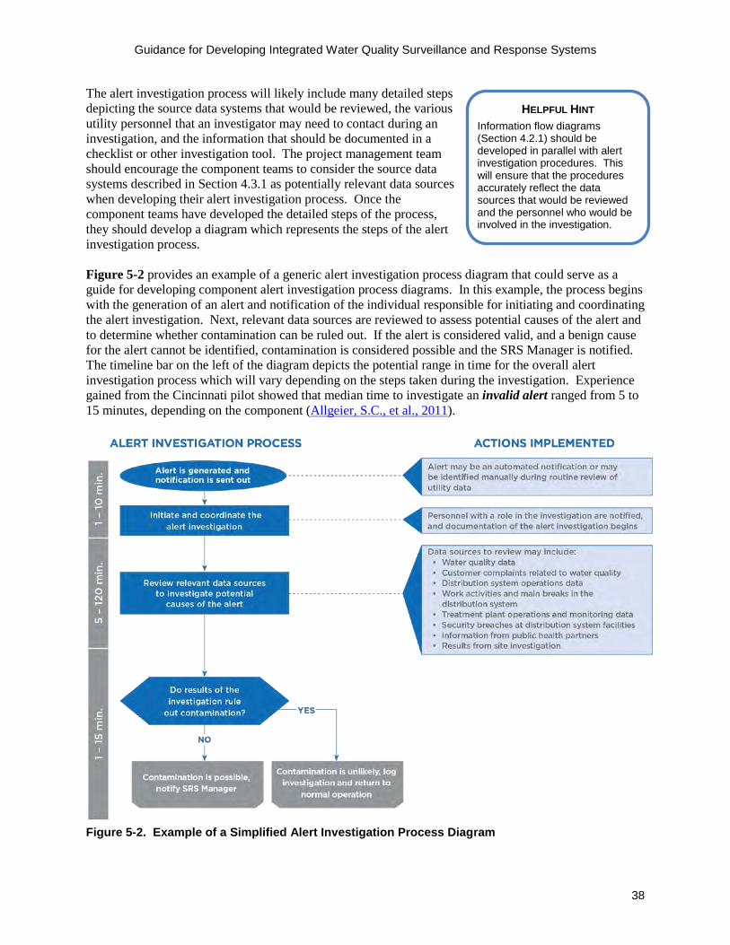
Guidance for Developing Integrated Water Quality Surveillance and Response Systems
38
The alert investigation process will likely include many detailed steps depicting the source data systems that would be reviewed, the various utility personnel that an investigator may need to contact during an investigation, and the information that should be documented in a checklist or other investigation tool. The project management team should encourage the component teams to consider the source data systems described in Section 4.3.1 as potentially relevant data sources when developing their alert investigation process. Once the component teams have developed the detailed steps of the process, they should develop a diagram which represents the steps of the alert investigation process. Figure 5-2 provides an example of a generic alert investigation process diagram that could serve as a guide for developing component alert investigation process diagrams. In this example, the process begins with the generation of an alert and notification of the individual responsible for initiating and coordinating the alert investigation. Next, relevant data sources are reviewed to assess potential causes of the alert and to determine whether contamination can be ruled out. If the alert is considered valid, and a benign cause for the alert cannot be identified, contamination is considered possible and the SRS Manager is notified. The timeline bar on the left of the diagram depicts the potential range in time for the overall alert investigation process which will vary depending on the steps taken during the investigation. Experience gained from the Cincinnati pilot showed that median time to investigate an invalid alert ranged from 5 to 15 minutes, depending on the component (Allgeier, S.C., et al., 2011).
Figure 5-2. Example of a Simplified Alert Investigation Process Diagram
HELPFUL HINT Information flow diagrams (Section 4.2.1) should be developed in parallel with alert investigation procedures. This will ensure that the procedures accurately reflect the data sources that would be reviewed and the personnel who would be involved in the investigation.
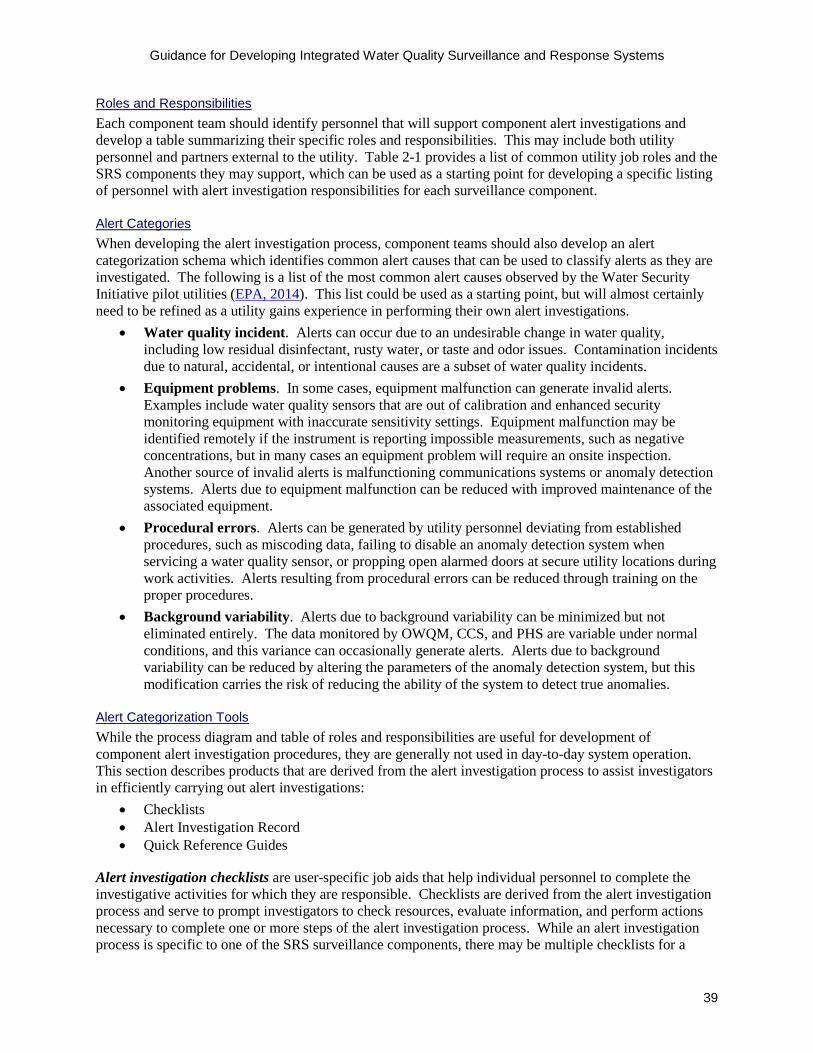
Guidance for Developing Integrated Water Quality Surveillance and Response Systems
39
Roles and Responsibilities Each component team should identify personnel that will support component alert investigations and develop a table summarizing their specific roles and responsibilities. This may include both utility personnel and partners external to the utility. Table 2-1 provides a list of common utility job roles and the SRS components they may support, which can be used as a starting point for developing a specific listing of personnel with alert investigation responsibilities for each surveillance component. Alert Categories When developing the alert investigation process, component teams should also develop an alert categorization schema which identifies common alert causes that can be used to classify alerts as they are investigated. The following is a list of the most common alert causes observed by the Water Security Initiative pilot utilities (EPA, 2014). This list could be used as a starting point, but will almost certainly need to be refined as a utility gains experience in performing their own alert investigations.
• Water quality incident. Alerts can occur due to an undesirable change in water quality, including low residual disinfectant, rusty water, or taste and odor issues. Contamination incidents due to natural, accidental, or intentional causes are a subset of water quality incidents.
• Equipment problems. In some cases, equipment malfunction can generate invalid alerts. Examples include water quality sensors that are out of calibration and enhanced security monitoring equipment with inaccurate sensitivity settings. Equipment malfunction may be identified remotely if the instrument is reporting impossible measurements, such as negative concentrations, but in many cases an equipment problem will require an onsite inspection. Another source of invalid alerts is malfunctioning communications systems or anomaly detection systems. Alerts due to equipment malfunction can be reduced with improved maintenance of the associated equipment.
• Procedural errors. Alerts can be generated by utility personnel deviating from established procedures, such as miscoding data, failing to disable an anomaly detection system when servicing a water quality sensor, or propping open alarmed doors at secure utility locations during work activities. Alerts resulting from procedural errors can be reduced through training on the proper procedures.
• Background variability. Alerts due to background variability can be minimized but not eliminated entirely. The data monitored by OWQM, CCS, and PHS are variable under normal conditions, and this variance can occasionally generate alerts. Alerts due to background variability can be reduced by altering the parameters of the anomaly detection system, but this modification carries the risk of reducing the ability of the system to detect true anomalies.
Alert Categorization Tools While the process diagram and table of roles and responsibilities are useful for development of component alert investigation procedures, they are generally not used in day-to-day system operation. This section describes products that are derived from the alert investigation process to assist investigators in efficiently carrying out alert investigations:
• Checklists • Alert Investigation Record • Quick Reference Guides
Alert investigation checklists are user-specific job aids that help individual personnel to complete the investigative activities for which they are responsible. Checklists are derived from the alert investigation process and serve to prompt investigators to check resources, evaluate information, and perform actions necessary to complete one or more steps of the alert investigation process. While an alert investigation process is specific to one of the SRS surveillance components, there may be multiple checklists for a
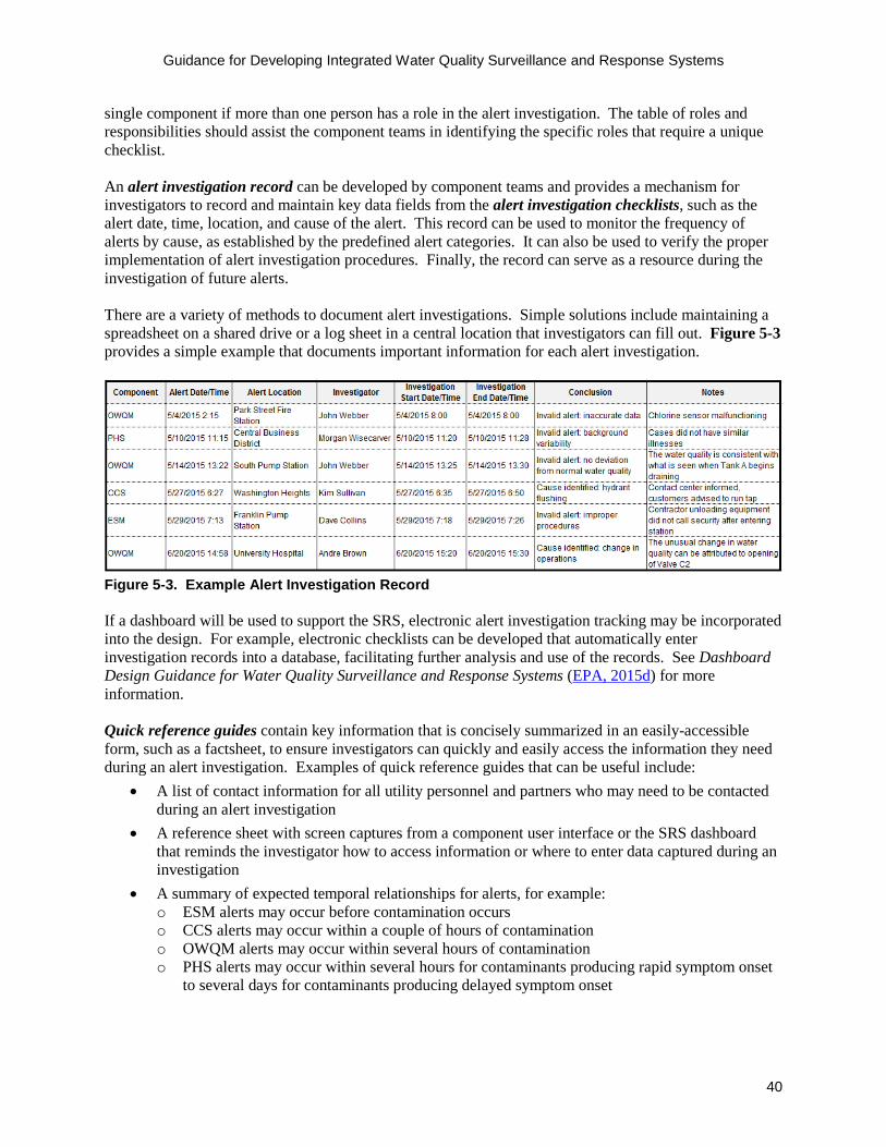
Guidance for Developing Integrated Water Quality Surveillance and Response Systems
40
single component if more than one person has a role in the alert investigation. The table of roles and responsibilities should assist the component teams in identifying the specific roles that require a unique checklist. An alert investigation record can be developed by component teams and provides a mechanism for investigators to record and maintain key data fields from the alert investigation checklists, such as the alert date, time, location, and cause of the alert. This record can be used to monitor the frequency of alerts by cause, as established by the predefined alert categories. It can also be used to verify the proper implementation of alert investigation procedures. Finally, the record can serve as a resource during the investigation of future alerts. There are a variety of methods to document alert investigations. Simple solutions include maintaining a spreadsheet on a shared drive or a log sheet in a central location that investigators can fill out. Figure 5-3 provides a simple example that documents important information for each alert investigation.
Figure 5-3. Example Alert Investigation Record If a dashboard will be used to support the SRS, electronic alert investigation tracking may be incorporated into the design. For example, electronic checklists can be developed that automatically enter investigation records into a database, facilitating further analysis and use of the records. See Dashboard Design Guidance for Water Quality Surveillance and Response Systems (EPA, 2015d) for more information. Quick reference guides contain key information that is concisely summarized in an easily-accessible form, such as a factsheet, to ensure investigators can quickly and easily access the information they need during an alert investigation. Examples of quick reference guides that can be useful include:
• A list of contact information for all utility personnel and partners who may need to be contacted during an alert investigation
• A reference sheet with screen captures from a component user interface or the SRS dashboard that reminds the investigator how to access information or where to enter data captured during an investigation
• A summary of expected temporal relationships for alerts, for example: o ESM alerts may occur before contamination occurs o CCS alerts may occur within a couple of hours of contamination o OWQM alerts may occur within several hours of contamination o PHS alerts may occur within several hours for contaminants producing rapid symptom onset
to several days for contaminants producing delayed symptom onset
Guidance for Developing Integrated Water Quality Surveillance and Response Systems
41
5.3 Review Component Alert Investigation Procedures for Consistency
Once the draft component alert investigation procedures are complete, the project management team should review them for consistency with respect to each other and with respect to the organizational and operational structure of the utility. This analysis should include a cross-component evaluation of the alert investigation process, roles and responsibilities, alert categories, and investigation tools. Alert Investigation Process The alert investigation processes should be reviewed to verify that there is a consistent approach used to determine if contamination is possible. The investigation process for each component should start with generation of an alert, include a review of data sources to help identify potential causes of the alert, and end with a determination of whether contamination is possible. In addition, the times required to complete various steps of the alert investigation should be compared across components, and large differences in the times required to complete similar steps should be reconciled. Streamlining the alert investigation process will result in more timely investigations. Notification steps in the process should be reviewed to determine whether the same individual(s) may receive notifications based on information generated from multiple components. Where this is the case, the mechanism for notification, as well as the information provided, should be consistent. The notifications should also be reviewed to determine if the correct personnel are being notified at the right time across the components. Roles and Responsibilities For each identified user, verify that their roles and responsibilities are consistent across all components and align with routine job functions. This review step can be facilitated by developing a tabular summary of roles and responsibilities that includes a list of all identified users, the description of their role, and a listing of their responsibilities for each component in which they have a role. Alert Categories The alert categories and descriptions should be consistent across components to ensure that similar types of alerts are being categorized in a similar manner, and that component teams have a common understanding of the difference between valid and invalid alerts. This review can ensure that component teams understand when to escalate an alert to possible contamination. Alert Investigation Tools Review of the user-specific checklists, alert investigation record, and quick reference guides developed by the component teams allows the project management team to identify tools that might support multiple components. This review also provides an opportunity to ensure consistency in the format and layout of these tools across the components. When reviewing the checklists, the project management team should determine if some users would be involved in alert investigations for more than one component. For example, it is likely that the water quality supervisor would have a role in OWQM and CCS alert investigations. In such cases, the checklists should clearly indicate the component name so it is easy for the user to understand which checklist needs to be completed for a specific component alert. The project management team should also identify common fields that should be recorded in the alert investigation record for all components.
HELPFUL HINT Ensure component alert investigation process descriptions strike a good balance between ease of use and comprehensiveness. Unnecessarily complex processes could impede the investigation.

Guidance for Developing Integrated Water Quality Surveillance and Response Systems
42
Upon completion of review of the alert investigation procedures, the project management team should provide final instructions to the component teams as to how to update their procedures. Finally, it is recommended that the alert investigation procedures be evaluated during preliminary operation through drills and exercises, and refined based on lessons learned, as discussed in Section 6.

Guidance for Developing Integrated Water Quality Surveillance and Response Systems
43
Section 6: Training and Exercise Program
Effective operation of an SRS requires that personnel clearly understand their role in the associated procedures. This can be achieved through implementation of a comprehensive training and exercise program. The overall goals of an SRS training and exercise program are to:
• Familiarize utility staff and response partners with their roles in SRS operations • Design, test, evaluate, and refine SRS procedures such as alert investigation procedures and the
Consequence Management Plan (CMP) • Test and evaluate the ability of utility personnel to implement SRS procedures • Test and evaluate communication and coordination with response partners • Identify opportunities to improve plans and procedures, particularly the time and accuracy with
which procedures are implemented Ultimately, a training and exercise program improves the efficacy with which utility personnel perform routine surveillance and respond to valid SRS alerts. Additionally, an effective training and exercise program is useful for integrating SRS procedures with existing utility procedures and those of external partners. This section provides general guidance on implementing a training and exercise program for an SRS. An interactive software program, the SRS Exercise Development Toolbox, is also available for designing, conducting, and evaluating drills and exercises for an SRS (EPA, 2015g). 6.1 Overview of an SRS Training and Exercise Program A training and exercise program for an SRS should be based on guidance provided by the Homeland Security Exercise and Evaluation Program (HSEEP), which constitutes a national standard for all types of exercises. The HSEEP is maintained by the Federal Emergency Management Agency’s National Preparedness Directorate, Department of Homeland Security. The HSEEP is a capabilities and performance-based exercise program that provides a standardized methodology and terminology for exercise design, development, conduct, evaluation, and improvement planning. The HSEEP describes two types of exercises:
• Discussion-based exercises include seminars, workshops, and tabletops to develop and teach new procedures
• Operations-based exercises include drills, functional exercises, and full-scale exercises to test and evaluate the effectiveness of procedures
A comprehensive SRS training and exercise program should include both discussion-based and operations-based exercises, and each exercise should have defined objectives, participants, duration, and level of complexity. Additional information concerning discussion-based and operations-based exercises for an SRS is presented in the following sections.
HELPFUL HINT Utilities should consider identifying a training coordinator who is ultimately responsible for overseeing the utility’s training program. This includes planning and designing drills and exercises, coordinating with response partners, maintaining evaluation records, and ensuring that Continuing Education Units or other training credits are received.

Guidance for Developing Integrated Water Quality Surveillance and Response Systems
44
6.2 Discussion-based Exercises Discussion-based exercises are typically used as a starting point in a comprehensive training and exercise program. This type of exercise is often used to familiarize utility personnel and response partners with SRS procedures and their role in implementing those procedures. Discussion-based exercises for an SRS should include seminars, workshops, and tabletop exercises as further described below.
6.2.1 Seminars Seminars are used to familiarize participants with SRS procedures and to learn about the capabilities of various response partners. Seminars are generally led by a presenter or facilitator in a classroom type-setting using a lecture-based, question-and-answer format. The duration of SRS seminars can range from one to six hours depending on the complexity of the topic. Table 6-1 describes some of the specific seminars that may be conducted as part of an SRS.
Table 6-1. Example SRS Seminars Seminar Description Participants Incident Command System (ICS) and National Incident Management System (NIMS)
Provide a basic understanding of ICS procedures and an introduction to the NIMS. Could include ICS course 100, 200, and NIMS 700 training.
All personnel who will have a role in the utility ICS.
SRS Orientation Provide an overview of the SRS including both routine surveillance and response.
All personnel who have a potential role in the operation and maintenance of an SRS.
Alert Investigation Procedures for Surveillance Components
Provide a basic understanding of the SRS surveillance components as well as their associated alert investigation procedures. These would typically be conducted as individual seminars for each SRS surveillance component.
Utility personnel and any external partners with responsibilities for routine monitoring of an SRS component.
Consequence Management Provide a basic understanding of the processes and procedures outlined in the SRS Consequence Management Plan.
Utility personnel and response partners who have a role in consequence management activities.
External Partner Engagement Provide a basic understanding of the process for identifying and engaging external partners who have a role in the SRS.
Utility management and utility personnel who have a need to interact with external partners during design or operation of the SRS.
Site Characterization Orientation Provide a basic understanding of the site characterization procedures that support investigative activities during consequence management.
Utility site characterization team members, laboratory personnel, HazMat, and local law enforcement.

Guidance for Developing Integrated Water Quality Surveillance and Response Systems
45
6.2.2 Workshops Workshops are typically used to develop new concepts, procedures, or other products through a group consensus process. Similar to seminars, workshops are generally led by a presenter or facilitator in a classroom type-setting, but are designed around participant discussion rather than lectures. Workshops often use breakout sessions to explore parts of an issue with smaller groups. The overall outcome of the workshop is the creation of, or modifications to, consensus-based plans or procedures. The duration of SRS workshops typically range from two to eight hours depending on the complexity of the topic. Table 6-2 describes some of the specific workshops that may be conducted in support of an SRS.

Guidance for Developing Integrated Water Quality Surveillance and Response Systems
46
Table 6-2. Example SRS Workshops Workshop Description Participants Alert Investigation Procedures
Discuss and come to a consensus on the alert investigation procedures for each of the SRS surveillance components. Separate workshops should be held for each component.
All personnel who have a role during investigation of component alerts including any relevant external partners.
Consequence Management Plan
Discuss and come to a consensus on procedures and responsibilities documented in the Consequence Management Plan. Separate workshops can be held to address specific aspects of the plan, including operational responses, site characterization, public notification, and remediation and recovery.
All personnel who have a role in the Consequence Management Plan including the appropriate response partners.
Utility Incident Command System
Discuss and come to a consensus on the utility ICS. This includes outlining all roles and responsibilities within the ICS.
All personnel who have a role in the utility ICS.
Response Partner Integration
Discuss and come to a consensus on roles and responsibilities of response partners during suspected contamination incidents.
Command staff of the utility ICS and appropriate response partners.
6.2.3 Tabletop Exercises Tabletop exercises are scenario-based and are designed to test and evaluate SRS procedures with all participants located in a classroom setting. Tabletop exercises are typically designed to allow participants to demonstrate proficiency in applying procedures in the context of a realistic scenario, identifying deficiencies in existing procedures, and building experience for operating the SRS.
Tabletop exercises require an experienced facilitator who can encourage in-depth discussion and help participants to make decisions through slower-paced problem-solving rather than the rapid, spontaneous decision-making that occurs during an actual emergency or an operations-based exercise (as discussed in Section 6.3). The duration of tabletops typically ranges from two to eight hours depending on the type and complexity of the scenario used.
Following a tabletop exercise, an after-action report is typically prepared. The after-action report captures observations made by evaluators during the exercise and provides recommendations for post-exercise improvements. The after-action report also contains an improvement plan, which identifies specific corrective actions, assigns them to responsible parties, and establishes target dates for their completion. Table 6-3 describes some of the specific tabletops that may be conducted in support of an SRS.
HELPFUL HINT Contamination scenarios are necessary to test and evaluate the simulated actions taken by exercise participants. Creating a credible and realistic scenario is critical to the success of an exercise. A credible scenario will keep players engaged and maintain their interest in the exercise.

Guidance for Developing Integrated Water Quality Surveillance and Response Systems
47
Table 6-3. Example SRS Tabletops Tabletop Exercise Description Participants Component Alert Investigation Procedures
Develop scenarios and conduct tabletop exercises for the SRS surveillance components. Separate exercises should be held for each component.
All personnel from the utility and external partners who have a role in component alert investigation procedures.
Consequence Management Develop scenarios and conduct tabletop exercises on the process flows and procedures in the Consequence Management Plan. This can range from a large exercise of the entire plan to smaller exercises for the various consequence management procedures.
All personnel who have a role in the Consequence Management Plan including the appropriate response partners.
The following case study describes a tabletop exercise conducted at one of the Water Security Initiative pilot utilities which focused on one aspect of Consequence Management – the threat level determination process.
6.3 Operations-based Exercises Once utility personnel and response partners have solidified SRS procedures through discussion-based exercises, the utility can validate the procedures by conducting operations-based exercises. These exercises should be used to test and evaluate the alert investigation procedures and Consequence Management Plan in order to clarify roles and responsibilities, identify gaps in resources needed to implement procedures, and ultimately to improve performance. While discussion-based exercises consist of a facilitated conversation in a classroom-style setting, operations-based exercises involve spontaneous reaction and response by participants to scenario details in a timeframe closely resembling that which would occur during a real contamination incident. Overall, operations-based exercises are more complex and detailed than discussion-based exercises and require more time to develop and conduct. Operations-based exercises for an SRS should include drills, functional exercises, and full-scale exercises as further described below.
6.3.1 Drills Drills are used to test a specific operation or function of the SRS through a coordinated and supervised activity. During an SRS drill, participants gain training and practice on the use of new equipment, such as site characterization equipment, test new or updated procedures, and prepare for more complex exercises such as functional and full-scale exercises. The duration of SRS drills typically ranges from one to six hours depending on the complexity of the procedures evaluated and the scenario used.
DISCUSSION-BASED EXERCISE CASE STUDY A tabletop exercise was designed and conducted to assess the threat level determination process in the Consequence Management Plan. Members of the utility’s ICS were presented with a series of contamination scenarios involving different types of contaminants, each of which unfolded with progressive information disclosure, including component alerts and associated information (e.g., alert locations, water quality changes, customer complaints, public health findings, etc.), results from site characterization, and results of laboratory analysis.
At each point where new information was disclosed, the participants were asked to determine if the threat level was possible, credible, or confirmed. Additionally, they were asked to identify the response actions they would consider, such as operational changes, notification of public health partners, public notification of use restriction(s), site characterization and sample collection, and laboratory analysis of collected samples. Exercise participants noted many benefits, including a more concrete understanding of the types and combinations of alerts that lead the utility ICS to conclude that contamination is possible, credible, or confirmed.
Guidance for Developing Integrated Water Quality Surveillance and Response Systems
48
While drills are often designed around a single component, they can involve multiple components. For example, one of the Water Security Initiative pilot utilities combined a CCS and site characterization drill by incorporating an investigation of clustered customer calls with the process for selecting a site for sampling and field testing. Creating a drill that combines closely related aspects from multiple components not only provides an opportunity for coordination between components, but can save time and conserve funding. Table 6-4 provides example SRS drills.
Table 6-4. Example SRS Drills Title Description Participants Component Alert Investigation Procedure Drills
Test the alert investigation procedures for each SRS component with participants situated at their normal workstation or in the field, and responding to scenario details in real-time.
All personnel from the utility and external partners who have a role in component alert investigation procedures.
Site Characterization Drills
Field response personnel and partners practice implementation of site characterization and sampling procedures/equipment.
All personnel from the utility and external partners who have a role in specific site characterization activities.
6.3.2 Functional and Full-scale Exercises Functional exercises are a single or multi-agency activity designed to test and evaluate multiple procedures, such as an end-to-end test of the SRS, and provide training for those who would use them in a real situation using a simulated response. Typically, all participants are gathered in a single room rather than at their workstations, and no field activities are performed. Unlike a tabletop exercise, a functional exercise is intended to operate in a pseudo real-time environment and without facilitation. However, an exercise controller may provide injects, which are scripted events or information, to move the exercise forward and indicate the result of certain actions taken by participants.
In contrast, a full-scale exercise is a multi-agency activity involving implementation of response actions as if a real incident had occurred. For an SRS, this would typically involve a full end-to-end test of a utility’s alert investigation procedures and Consequence Management Plan. Participants respond from their normal workstations, field activities such as sample collection are performed, and procedures are implemented in real-time when practical. Unlike tabletop exercises, where the pace of the scenario is driven by a facilitator who can slow down the discussion to ensure the participants improve their understanding of procedures, the pace of functional and full-scale exercises is driven by participants who are responsible for making decisions in a time-pressured environment.
Given that functional and full-scale exercises for an SRS typically involve end-to-end tests of many detailed procedures, they require the participation of all designated utility personnel and response partners identified in the utility’s alert investigation procedures and Consequence Management Plan. Due to the complexity of these exercises and the number of personnel involved, exercise development planning should begin at least six months prior to the exercise. The actual exercise usually takes place over a one to two day period.
The following case study describes a full-scale exercise conducted at one of the Water Security Initiative pilot utilities.
HELPFUL HINT It is recommended that a utility conduct a functional exercise prior to conducting their first full-scale exercise. This will allow the utility and response partners to practice their procedures in a less stressful environment. In addition, lessons learned from the functional exercise can prepare participants for a more involved full-scale exercise.

Guidance for Developing Integrated Water Quality Surveillance and Response Systems
49
OPERATIONS-BASED EXERCISE CASE STUDY A full-scale exercise was designed and conducted to test the SRS investigation and response procedures, and assess the level of preparedness of the utility and its external partners to respond to possible water contamination. The exercise was held during a 2-day period and involved approximately 100 participants. The contamination scenario involved an OWQM alert, customer complaints received via 311 and Twitter, and reports of illness from public health partners. Once contamination was deemed possible, utility field crews and response partners were deployed to perform site characterization activities in the field. Later in the scenario, the players received simulated laboratory analysis results which identified the presence of aldicarb, a toxic pesticide, in finished water reservoir samples. As the scenario unfolded and the threat level transitioned from possible to credible and finally confirmed contamination, the response was escalated from the internal utility operations center to the city emergency operations center. The scenario allowed the utility to test activation of the utility operations center, coordination with response partners such as HazMat, and implementation of response measures including containment of water in the distribution system and issuance of public health notifications.
In the weeks following the exercise, the utility addressed areas for improvement by updating their consequence management plan with the specific conditions that would result in activation of response partners, and solidified notification protocols. The utility also developed a training schedule to practice ICS principles at the operations center and scheduled a meeting with the public health partners to develop templates for public notifications that could be used during a contamination incident.
6.4 Implementing an SRS Training and Exercise Program Figure 6-1 illustrates a systematic, progressive approach to developing an SRS training and exercise program. It begins with development of procedures and building a broad, sound foundation of SRS knowledge among utility and response partner personnel through a series of discussion-based exercises. This is followed by drills of limited scope to build proficiency in specific areas, and finally culminates in functional and full-scale exercises.
Operations-based Exercises
Discussion-based Exercises
Figure 6-1. Progression of an SRS Training and Exercise Program
An SRS training and exercise program will evolve over the course of SRS implementation. The training and exercise program will tend to be more extensive at first in order to establish and refine procedures, as

Guidance for Developing Integrated Water Quality Surveillance and Response Systems
50
well as educate personnel responsible for implementing those procedures. Once the SRS is fully operational, the training and exercise program may be scaled back to focus on refresher training and training for new employees.
During the initial phases of SRS implementation, typically during the first two years, the training program might proceed as follows:
1. Seminars and tabletop exercises to evaluate and refine SRS procedures2. Functional exercise to provide staff with an opportunity to practice use of multiple SRS
procedures3. Full-scale exercises to apply SRS procedures during a simulated contamination incident
If a utility has decided on a phased implementation approach and is designing and implementing one component at a time, the initial set of exercises may be limited in scope to test the alert investigation procedures for the first component and potentially bridge over into Consequence Management procedures. Once more components are implemented, the utility will be able to design and conduct more complex exercises to observe multiple component alert investigations and a more fully developed strategy for Consequence Management.
Once the initial training period has passed and the SRS is in real-time operation, the utility should conduct annual training to maintain proficiency in the implementation of SRS procedures. This training should be coordinated through a multi-year training and exercise plan and integrated into a utility’s existing training program if one is already in place. The training coordinator, or other personnel designated by the utility to oversee trainings and exercises, should ensure that SRS documents are updated based on the improvement plan documented in after-action reports. To learn more, refer to the EPA document, How to Develop a Multi-Year Training and Exercise Plan (EPA, 2011).
HELPFUL HINT One of the major dual-use benefits of conducting exercises is that they can be used to fulfill state or local training requirements. For example, Continuing Education Units or Training Contact Hours can be applied towards operator licenses as well as city requirements for training hours. Similarly, partner organizations can often receive credit towards their training requirements.
Guidance for Developing Integrated Water Quality Surveillance and Response Systems
51
Resources Introduction Water Quality Surveillance and Response System Primer (EPA, 2015a)
http://www.epa.gov/waterqualitysurveillance/water-quality-surveillance-and-response-system-fact-sheet-and-primer This document provides an overview of SRSs for drinking water distribution systems. It covers possible applications of an SRS, provides information about the monitoring and surveillance components, covers common design goals and performance objectives, and includes an overview of the approach for implementing an SRS. EPA 817-B-15-002, May 2015.
Summary of Implementation Approaches and Lessons Learned from the Water Security Initiative Contamination Warning System Pilots (EPA, 2015b)
http://www.epa.gov/waterqualitysurveillance/water-quality-surveillance-and-response-system-case-studies This report provides a summary of key findings from five water utilities that participated in a pilot program to design and demonstrate a sustainable Contamination Warning System capable of providing timely detection of and response to drinking water contamination incidents in the water distribution system. Specifically, this document provides a concise overview of implementation approaches and lessons learned from the pilots that are potentially useful to future SRS implementers. EPA 817-R-15-002, October 2015.
Master Planning Framework for Comparing Alternatives for Water Quality Surveillance and Response Systems (EPA, 2015c)
http://www.epa.gov/waterqualitysurveillance/surveillance-and-response-system-resources This document provides guidance for selecting the most appropriate SRS design for a utility from a set of viable alternatives. It guides the user through an objective, stepwise analysis for ranking multiple alternatives and describes, in general terms, the types of information necessary to perform the comparison of alternatives. EPA 817-B-15-003, June 2015.
Information Management Dashboard Design Guidance for Water Quality Surveillance and Response Systems (EPA, 2015d)
http://www.epa.gov/waterqualitysurveillance/surveillance-and-response-system-resources This document provides information about useful features and functions that can be incorporated into an SRS dashboard. It also provides guidance on a systematic approach that can be used by utility managers and IT personnel engaged in the process of designing a dashboard to define requirements.
Information Management Requirements Development Tool (EPA, 2015e) http://www.epa.gov/waterqualitysurveillance/surveillance-and-response-system-resources This tool is intended to help users develop requirements for an SRS information management system, thereby preparing them to select and implement an information management solution. Specifically, this tool (1) assists SRS component teams with development of component functional requirements, (2) assists IT personnel with development of technical requirements, and (3) allows the IT design team to efficiently consolidate and review all requirements. EPA 817-B-15-004, October 2015.

Guidance for Developing Integrated Water Quality Surveillance and Response Systems
52
Guidance for Designing Communications Systems for Water Quality Surveillance and Response Systems (EPA, 2015f)
http://www.epa.gov/waterqualitysurveillance/surveillance-and-response-system-resources This guidance document describes the approach for evaluating and selecting communications technologies to support operation of OWQM, ESM, and other SRS components that need to transmit data. The document provides users with a description of attributes that should be considered when evaluating communications systems alternatives and a general assessment of common technologies relative to these attributes.
Cybersecurity Guidance & Tool (AWWA, 2014) http://www.awwa.org/resources-tools/water-and-wastewater-utility-management/cybersecurity-guidance.aspx This website contains links to a guidance document and tool. The guidance document includes a list of recommended cybersecurity considered to be the most critical for managing the process control system cybersecurity risk in the water sector. These recommended practices are further defined by a set of 82 cybersecurity controls that represent the more granular measures necessary to support implementation of the recommended practices. The cybersecurity tool generates a prioritized list of recommended controls based on specific characteristics of the utility. The user provides information about their process control system and the manner in which it is used by choosing from a number of pre-defined use cases. For each recommended control, specific references to existing cybersecurity standards are also provided.
Training and Exercise Program SRS Exercise Development Toolbox (EPA, 2015g)
http://www.epa.gov/waterresiliencetraining An interactive software application designed to aid drinking water utilities in developing, conducting, and evaluating discussion-based and operations-based exercises for an SRS. It guides users through a process to enter the information necessary to develop a drill or exercise and then generates the required documentation.
How to Develop a Multi-Year Training and Exercise Plan (EPA, 2011) http://www.epa.gov/waterresiliencetraining/develop-water-utility-training-and-exercise-plan This document provides information to assist utilities in creating multi-year training and exercise plans that can lead to increased emergency preparedness. The material included in the document is based on HSEEP. EPA 816-K-11-003, May 2011.

Guidance for Developing Integrated Water Quality Surveillance and Response Systems
53
References Allgeier, S.C., Haas, A.J., and Pickard, B.C., 2011. Optimizing Alert Occurrence in the Cincinnati
Contamination Warning System. Journal of the American Water Works Association, 103:10.
EPA, 2014. Water Security Initiative: System Evaluation of the Cincinnati Contamination Warning System Pilot, EPA 817-R-14-001A.
Umberg, K. and Allgeier, S.C., 2016. Parameter Setpoints: An Effective Solution for Real-time Data Analysis. Journal of the American Water Works Association, 108:1.
Guidance for Developing Integrated Water Quality Surveillance and Response Systems
54
Glossary alert. An indication from an SRS surveillance component that an anomaly has been detected in a datastream monitored by that component. Alerts may be visual or audible, and may initiate automatic notifications such as pager, text, or email messages.
alert investigation. The process of investigating the validity and potential causes of an alert generated by an SRS surveillance component.
alert investigation checklist. A form that lists a sequence of steps to follow when investigating an SRS alert. This form ensures consistency with an alert investigation procedure and provides documentation of the investigation of each alert.
alert investigation procedure. A documented process that guides the investigation of an SRS alert. A typical procedure defines roles and responsibilities for alert investigations, includes an investigation process diagram, and provides one or more checklists to guide investigators through their role in the process.
alert investigation record. A repository or database of completed alert investigations that documents the actions taken, conclusion of the investigation, and likely cause of the alert. An alert investigation record can be maintained in an electronic or paper format.
anomaly. A deviation from an established baseline in a monitored datastream. Detection of an anomaly by an SRS surveillance component generates an alert.
anomaly detection system. An automated tool which continually analyzes data and generates an alert if the data deviates from an established baseline. An anomaly detection system may take a variety of forms, ranging from complex computer algorithms to a simple set of heuristics that are manually implemented.
architecture. The fundamental organization of a system embodied in its components, their relationships to each other, and to the environment, and the principles guiding its design and evolution. The architecture of an information management system is conceptualized as three tiers: source data systems, analytical infrastructure, and presentation.
baseline. Values for a datastream that include the variability observed during typical system conditions.
benefit. An outcome associated with the implementation and operation of an SRS that promotes the welfare of a utility and the community it serves. Benefits can be derived from a reduction in the consequences of a contamination incident and from improvements to routine operations.
call management system. Software that manages customer calls received by a utility, which may include functionality to classify and direct calls.
case-based surveillance. A form of public health surveillance in which frontline healthcare providers detect potential public health incidents through the cumulative assessment of case details or case volume.
component. One of the primary functional areas of an SRS. There are four surveillance components: Online Water Quality Monitoring; Enhanced Security Monitoring; Customer Complaint Surveillance; and Public Health Surveillance. There are two response components: Consequence Management and Sampling and Analysis.
Guidance for Developing Integrated Water Quality Surveillance and Response Systems
55
component team. A designated group of individuals responsible for design and implementation of an SRS component.
confirmed. In the context of the threat level determination process, contamination is confirmed when the analysis of all available information provides definitive, or nearly definitive, evidence of the presence of a specific contaminant or contaminant class in a distribution system. While positive results from laboratory analysis of a sample collected from a distribution system can be a basis for confirming contamination, a preponderance of evidence, without the benefit of laboratory results, can lead to this same determination.
Consequence Management (CM). One of the response components of an SRS. This component encompasses actions taken to plan for and respond to possible drinking water contamination incidents to minimize the response and recovery timeframe, and ultimately minimize consequences to a utility and the public.
Consequence Management Plan (CMP). A planned decision-making framework that establishes roles and responsibilities and guides the investigative and response actions following a determination that distribution system contamination is possible.
constraints. Requirements or limitations that may impact the viability of an alternative. The primary constraints for an SRS project are typically schedule, budget, and policy issues (for example, zoning restrictions, IT restriction, and union prohibitions).
contamination incident. The presence of a contaminant in a drinking water distribution system that has the potential to cause harm to a utility or the community served by the utility. Contamination incidents may have natural (e.g., toxins produced by a source water algal bloom), accidental (e.g., chemicals introduced through an accidental cross-connection) or intentional (e.g., purposeful injection of a contaminant at a fire hydrant) causes.
contamination scenario. A simulated contamination incident.
continuous monitoring. Uninterrupted collection and analysis of data. Collection and analysis frequency can range from seconds to hours.
credible. In the context of the threat level determination process, a contamination incident is characterized as credible if information collected during the investigation of possible contamination corroborates information from a validated SRS alert.
Customer Complaint Surveillance (CCS). One of the surveillance components of an SRS. CCS monitors water quality complaint data in call or work management systems and identifies abnormally high volumes or spatial clustering of complaints that may be indicative of a contamination incident.
customer service representative (CSR). Personnel at a utility or city contact center who receive customer information or interact with customers. These personnel often resolve issues related to water quality, service, or billing.
cybersecurity. Measures implemented to protect an information management system and network from unauthorized access, damage, or attack. Common examples include password protected computers, encryption, and use of anti-virus software.
dashboard. A visually-oriented user interface that integrates data from multiple SRS components to provide a holistic view of distribution system water quality. The integrated display of information in a

Guidance for Developing Integrated Water Quality Surveillance and Response Systems
56
dashboard allows for more efficient and effective management of distribution system water quality and the timely investigation of water quality incidents.
data access. The process of retrieving data from an information management system for review and analysis.
data analysis. The process of analyzing data to support routine system operation, rapid identification of water quality anomalies, and generation of alert notifications.
data historian. A software application or database that is designed to store large volumes of information. Data historians are usually separate from the primary information management system.
data management. The process of capturing, processing, and storing data.
datastream. A time series of values for a unique parameter or set of parameters. Examples of SRS datastreams include, chlorine residual values, water quality complaint counts, and number of emergency department cases.
design basis threat. The threat against which an asset must be protected and upon which the design of a protective system is based. It includes the tactics and tools that aggressors will use against the asset.
design goal. The specific benefits to be realized through deployment of an SRS and each of its components. A fundamental design goal of an SRS is detecting and responding to distribution system contamination incidents. Additional design goals for an SRS are established by a utility and often include benefits to routine utility operations.
design sub-element. Features, capabilities, or attributes that comprise a design element. In general, the information presented in SRS guidance and products is organized by design elements and sub-elements.
diagnostics. Processes used to examine the state of, and locate problems with, equipment, hardware or software.
distribution system model. A mathematical representation of a drinking water distribution system, including pipes, junctions, valves, pumps, tanks, reservoirs, and other appurtenances. These models predict flow and pressure of water through the system, and, in some cases, water quality.
emergency management agency. Emergency planning committees and emergency management departments that primarily support response activities and coordinate with other response agencies. These agencies may operate at the federal, state, or local level.
emergency operations center. A staffed facility that is responsible for carrying out emergency preparedness and emergency management functions at a strategic level in an emergency situation. Personnel collect and analyze data, disseminate information to all concerned agencies, and locate needed resources.
Enhanced Security Monitoring (ESM). One of the surveillance components of an SRS. ESM includes the equipment and procedures used to detect and respond to security breaches at distribution system facilities that are vulnerable to contamination.
external partners. Entities outside the water utility that may be involved in a variety of SRS support functions, including system design, monitoring, investigating alerts, and responding contamination
Guidance for Developing Integrated Water Quality Surveillance and Response Systems
57
incidents. Typical external partners include local law enforcement, HazMat unit, and public health agencies.
functional requirement. A type of information management requirement that defines key features and attributes of an information management system that are visible to the end user. Examples of functional requirements include the manner in which data is accessed, types of tables and plots that can be produced through the user interface, the manner in which component alerts are transmitted to investigators, and the ability to generate custom reports.
geographic information system (GIS). Hardware and software used to store, manage, and display geographically referenced information. Typical information layers used by water utilities include utility infrastructure, hydrants, service lines, streets, and hydraulic zones. A GIS can also be used to display information generated by an SRS.
hardware. A physical IT assets such as servers or user workstations.
HazMat unit. A specially trained unit of professionals with responsibility for responding to uncontrolled releases of hazardous materials. In situations where the presence of hazardous materials is suspected or discovered, HazMat units support implementation of site characterization activities.
historical data. Data that has been generated and stored, including recent data that is readily available in an information management system as well as older data that has been stored or archived in a historian.
implementation costs. Costs to procure and install equipment, IT components, and other assets necessary to build an operational system.
Incident Command System (ICS). A standardized, all-hazards emergency operations structure that is flexible and can be used for incidents of any type, scope, and complexity. ICS is a part of the National Incident Management System.
information management. The processes involved in the collection, storage, access, and visualization of information. In the context of an SRS, information includes the raw data generated by SRS surveillance components, alerts generated by the components, ancillary information used to support data analysis or alert investigation, details entered during alert investigations, and documentation of Consequence Management activities.
information management system. The combination of hardware, software, tools, and processes that collectively support an SRS and provides users with information needed to monitor real-time system conditions. The system allows users to efficiently identify, investigate, and respond to water quality incidents.
information technology (IT). Hardware, software, and data networks that store, manage, and process information.
inject. Information provided to participants verbally or in written format during a discussion-based or operations-based exercise to simulate an event that will drive the actions taken by the participants.
invalid alert. An alert from an SRS surveillance component that is not due to a water quality incident or public health incident.
Guidance for Developing Integrated Water Quality Surveillance and Response Systems
58
IT design team. Personnel responsible for selecting, designing, and implementing the SRS information management system.
lifecycle cost. The total cost of a system, component, or asset over its useful life. Lifecycle cost includes the cost of implementation, operation and maintenance, and renewal.
monitoring location. A specific point in the water distribution system where SRS component data is collected, such as the location of OWQM sensor hardware or an ESM video surveillance camera.
monitoring station. A configuration of one or more water quality sensors and associated support systems, such as plumbing, electric, and communications that is deployed to monitor water quality in real time at a specific location in a drinking water distribution system.
National Incident Management System (NIMS). A system that provides a consistent nationwide template to enable all government, private-sector, and nongovernmental organizations to work together during domestic incidents. NIMS works within the National Response Framework (NRF). NIMS provides the template for the management of incidents, while the NRF provides the structure and mechanisms for national-level policy for incident management.
National Response Framework (NRF). A framework that serves as a guide to national response to all types of disasters and emergencies. It is built on scalable, flexible, and adaptable concepts identified in the National Incident Management System to align key roles and responsibilities across the nation. This framework describes specific authorities and best practices for managing incidents that range from the serious but purely local to large-scale terrorist attacks or catastrophic natural disasters.
Online Water Quality Monitoring (OWQM). One of the surveillance components of an SRS. OWQM utilizes data collected from monitoring stations that are deployed at strategic locations in a distribution system. Monitored parameters can include common water quality parameters (e.g., chlorine residual, pH, specific conductance and turbidity) and advanced parameters (e.g., total organic carbon and UV-Vis spectral data). Data from distribution system monitoring locations is transferred to a central location and analyzed for water quality anomalies.
operational change. A change in the way the distribution system is operated, including changes in pumping or valving.
operations and maintenance (O&M) costs. Expenses incurred to sustain operation of a system at an acceptable level of performance. O&M costs are typically reported on an annual basis, and include labor and other expenditures, such as supplies and purchased services.
performance objectives. Measurable indicators of how well an SRS or its components meet established design goals.
Poison Control Center (PCC). An agency employing toxicologists, medical doctors, and other professions with pharmacological expertise for the purpose of providing guidance to persons who may have been exposed to a toxic substance, or to healthcare providers with responsibility for treating exposed persons.
possible. In the context of the threat level determination process, water contamination is considered possible if the cause of an alert from one of the surveillance components cannot be identified or determined to be benign.
Guidance for Developing Integrated Water Quality Surveillance and Response Systems
59
primacy agency. The organization responsible for overseeing drinking water utility compliance with drinking water regulations. In most cases the primacy agency is a state agency such as a state department of environmental protection, environmental quality, or public health.
project management team. A designated group of individuals responsible for overseeing all project activities, tracking the overall budget and schedule, and ensuring system integration.
public health incident. An occurrence of disease, illness, or injury within a population that is a deviation from the disease baseline in the population.
public health response plan. A plan that coordinates actions among public health agencies, emergency management agencies, and other partners to ensure a methodical response to public health incidents.
Public Health Surveillance (PHS). One of the surveillance components of an SRS. PHS involves the analysis of public health datastreams to identify public health incidents, and the investigation of such incidents to determine whether they may be due to drinking water contamination.
public notification. Official communication to utility customers regarding the quality and safety of their drinking water. A public notification may include instructions to customers, such as to not use the water for any purpose, not use the water for drinking, or boil the water before use.
quick reference guide. Factsheets or other summary briefs that contain key information that is concisely presented in an easily-accessible format to ensure that investigators can quickly and easily access the information they need during an alert investigation.
rapid field testing. Testing of drinking water samples in the field for chemical, biological, or radiochemical contaminants. Results provide decision-makers and laboratories with preliminary information that may help focus an investigation.
real-time. A mode of operation in which data describing the current state of a system is available in sufficient time for analysis and subsequent use to support assessment, control, and decision functions related to the monitored system.
remote access. The ability of a user to access an information management system from a location other than the physical location of the hardware that hosts the system.
response action. An action taken by a utility, public health agency or another response partner to minimize the consequences of an undesirable water quality incident. Response actions may include issuing a public notification, changing system operations, or flushing the system.
response partners. A subset of external partners that assist a water utility during emergency response activities such as site characterization, laboratory analysis, public notification, and provision of alternate water supply.
Sampling and Analysis (S&A). One of the response components of an SRS. S&A is activated during Consequence Management to help confirm or rule out possible water contamination through field and laboratory analyses of water samples. In addition to laboratory analyses, S&A includes all the activities associated with site characterization. S&A continues to be active throughout remediation and recovery if contamination is confirmed.

Guidance for Developing Integrated Water Quality Surveillance and Response Systems
60
setpoint. Minimum and maximum acceptable values for individual datastreams that are compared against current or recent data to determine whether conditions are anomalous, or atypical of normal operations. See also threshold.
setpoint alerting. A data analysis technique in which the user defines setpoints for individual datastreams and an alert is generated if a value is outside the range established by the setpoints. See also threshold alerting.
site characterization. The process of collecting information from the site of a suspected contamination incident. Site characterization activities include the site investigation, site safety screening, rapid field testing of the water, and sample collection.
site safety screening. The process of screening for environmental hazards at the site of a field investigation to help ensure worker safety. Typical site safety screening includes instrumentation for monitoring volatile or combustible gases and radiation.
software. A program that runs on a computer and performs certain functions.
solution. The design and configuration of the hardware, software, and other products that will be used to construct an information management system.
source data system. The application or database that houses and manages the source data used by one or more of the SRS components, and which forms a tier of the SRS information management system architecture.
SRS Manager. A role within an SRS typically filled by a mid- to upper-level manager from a drinking water utility. Responsibilities of this position include: receiving notification of valid alerts, coordinating the threat level determination process, integrating information across the different surveillance components, and activating the Consequence Management Plan.
standard operating procedure (SOP). A standardized process for accomplishing a task, operating a piece of equipment, or running a system.
Supervisory Control and Data Acquisition (SCADA). A system that collects data from various sensors at a drinking water treatment plant and locations in a distribution system, and sends this data to a central information management system.
technical requirement. A type of information management requirement that defines system attributes and design features that are often not readily apparent to the end user but are essential to meeting functional requirements or other design constraints. Examples include attributes such as system availability, information security and privacy, back-up and recovery, data storage needs, and integration requirements.
threat level determination process. A systematic process in which all relevant information available from an SRS is evaluated to determine whether contamination is possible, credible, or confirmed. This is an iterative process in which the threat level is revised as additional information becomes available. The conclusions from this process are considered during Consequence Management when making response decisions.
threshold. A value that is compared against current or recent data to determine whether conditions are anomalous, or atypical of normal operations. See also setpoint.
Guidance for Developing Integrated Water Quality Surveillance and Response Systems
61
time-series data. A sequence of ordered data points in which each point corresponds to a data value collected at a specific time. Time-series data is usually collected at a regular polling interval.
user interface. A visually oriented interface that allows a user to interact with an information management system. A user interface typically facilitates data access and analysis.
valid alert. Alerts due to water contamination, verified water quality incidents, intrusions at utility facilities, or public health incidents.
vulnerability. A weakness that can be exploited by an adversary.
water quality complaints. Complaints received by a utility from a customer indicating that water quality is not as expected. Traits such as an unusual taste, odor, or appearance can all indicate abnormal water quality within the distribution system.
water quality incident. An incident that results in an undesirable change in water quality (e.g., low residual disinfectant, rusty water, taste & odor, etc.). Contamination incidents are a subset of water quality incidents.
Water Quality Surveillance and Response System (SRS). A system that employs one or more surveillance components to monitor and manage distribution system water quality in real time. An SRS utilizes a variety of data analysis techniques to detect water quality anomalies and generate alerts. Procedures guide the investigation of alerts and the response to validated water quality incidents that might impact operations, public health, or utility infrastructure.
Water Security Initiative (WSI). A program developed by EPA to design, evaluate, and promote adoption of Water Quality Surveillance and Response Systems within the drinking water sector.
work management system. Software used by a utility to schedule and track maintenance, repair or other operations in the distribution system.
Guidance for Developing Integrated Water Quality Surveillance and Response Systems
62
Appendix A: Master Plan Template
Section 1.0: Project Scope This section should define the project scope for design of the Water Quality Surveillance and Response System, including a description of the design goals, performance objectives, and constraints. It should also include a concise yet meaningful vision statement for the SRS.
1.1 Design Goals List the design goals established for the SRS, which define the specific benefits that a utility would like to realize through implementation and operation of an SRS.
1.2 Performance Objectives Describe the performance objectives for the SRS which will be used to gauge how well the surveillance and response components, either individually or as a whole, achieve the established design goals.
1.3 Constraints Identify and document project constraints which will bound the design of the system, such as: capital budget, annual operating and maintenance budget, availability of essential personnel, and policy restrictions.
Section 2.0: Project Management This section should document the structure of project management and component teams, and establish the overarching project budget and schedule.
2.1 Project Management Team Include a list of utility personnel and partners who will compose the project management team. Note the roles and responsibilities of each team member.
2.2 Component Teams Include a list of utility personnel and partners who will compose the component teams. Note the roles and responsibilities of each team member.
2.3 Project Budget Define the overall project budget, including a breakout of the budget allocated to each component for each budget period.
2.4 Project Schedule Define the overall project schedule, including a breakout of the schedule for each component and noting interdependencies among project activities.
Section 3.0: Component Designs This section should include a summary of the design for each component to be implemented as part of the SRS. The following subsections provide examples of the type of information that might be included to describe the design of each component.

Guidance for Developing Integrated Water Quality Surveillance and Response Systems
63
3.1 Customer Complaint Surveillance • Information flow diagram • Alert investigation procedure • List of the partners who will need to be engaged to develop the component • Summary of the approach used to funnel and filter customer water quality complaints • Data management and analysis methods • Budget, including capital and annual operations and maintenance costs • Schedule, including the sequence and duration of activities and any key dependencies
3.2 Online Water Quality Monitoring
• Information flow diagram • Alert investigation procedure • List of the partners who will need to be engaged to develop the component • List of existing and proposed monitoring locations, noting the parameters that will be monitored
at each site • Cumulative summary of the major pieces of equipment needed to implement the component • Data communication, management, and analysis methods • Budget, including capital and annual operations and maintenance costs • Schedule, including the sequence and duration of activities and any key dependencies
3.3 Enhanced Security Monitoring
• Information flow diagram • Alert investigation procedure • List of the partners who will need to be engaged to develop the component • List of the utility distribution system facilities that will be enhanced under the component, and the
specific enhancements at each • Cumulative summary of the major pieces of equipment needed to implement the component • Data communication, management, and analysis methods • Budget, including capital and annual operations and maintenance costs • Schedule, including the sequence and duration of activities and any key dependencies
3.4 Public Health Surveillance
• Information flow diagram • Alert investigation procedure • List of the partners who will need to be engaged to develop the component • Strategy for improving communication and coordination with public health partners • Summary of the public health datastreams that will be monitored under the component • Data management and analysis methods • Budget, including capital and annual operations and maintenance costs • Schedule, including the sequence and duration of activities and any key dependencies
3.5 Consequence Management
• Listing and brief description of the procedures and documentation needed to support the component
• List of the partners who will need to be engaged to develop the component • List of equipment needed to implement the component • Budget, including capital and annual operations and maintenance costs • Schedule, including the sequence and duration of activities and any key dependencies

Guidance for Developing Integrated Water Quality Surveillance and Response Systems
64
3.6 Sampling and Analysis • Summary of the contaminants and contaminant classes that will be covered by the component and
the strategy for developing the field and laboratory analytical capabilities for each • Listing and brief description of the procedures and documentation needed to support the
component • List of the partners who will need to be engaged to develop the component • List of field and laboratory equipment needed to implement the component • Budget, including capital and annual operations and maintenance costs • Schedule, including the sequence and duration of activities and any key dependencies
Section 4.0: Information Management This section should include a summary of the requirements and solution for information management needed to support all components of the SRS.
• Listing of the partners that will need to be engaged to implement the information management solution
• Consolidated list of final functional and technical requirements • Summary description of the information management solution, including a physical architecture
diagram • Listing of the hardware, software, communication infrastructure, and other systems needed to
implement the SRS information management solution Section 5.0: Training and Exercise Program This section should include a general plan for developing and implementing an SRS training and exercises program.
• Strategy for progressive learning in which participants begin with simple activities and progress though increasingly complex activities
• Curriculum of training and exercises that includes both discussion-based and operations-based activities
• Approximate schedule for completing major training and exercise activities

Guidance for Developing Integrated Water Quality Surveillance and Response Systems
65
Appendix B: IT Operation and Maintenance Manual Template
Section 1.0: Introduction This section should describe the purpose of the manual, note the intended audience and provide an overview of the information contained within. Section 2.0: Overview of System Architecture This section should provide an overview of the SRS information management system. It should include an overarching physical architecture diagram for the SRS information management system. Supplemental architecture diagrams can be included as needed. Section 3.0: Description of Hardware and Software Elements Provide a detailed description of each hardware and software element used in the SRS information management system. A tabular summary of the information to document for each IT element, includes:
• Name: The name of the IT element. • Purpose: The general purpose served by the IT element in the context of the SRS information
management system architecture. • Summary Description: A summary description of the IT element. • Location: The location of the IT element. • Access: Procedure for accessing the IT element. • Vendor: Contact information for the vendor of the IT element, if applicable. • Warranty: Information about the warranty covering the IT element, if applicable. • License: Information about the license agreement, such as the number of users or installations, if
applicable. • Specifications: Detailed information about the item, such as hardware specifications, version,
programming language, acceptable formats, and any other relevant specifications. Section 4.0: Backup and Recovery Plan This section describes the backup and recovery plan for the SRS information management system, organized into subsections for each IT element with a distinct approach to backup and recovery. In general, the following types of information should be documented for each IT element:
• Frequency of backups • Location of backups • Recovery and restoration method • Specifications of uninterrupted power supplies
Section 5.0: Maintenance Plan Describe the maintenance plan for each IT element, as applicable. Maintenance activities could be summarized in a table that includes:
• Name: The name of the IT element.
Guidance for Developing Integrated Water Quality Surveillance and Response Systems
66
• Point of Contact: Contact information for the person responsible for maintaining the hardware or software element.
• Maintenance Activity: Description of the specific maintenance activity and a reference to the associated procedure, if available. (Note that there may be multiple maintenance activities per IT element.)
• Frequency: Schedule for performing the maintenance activity. Section 6.0: Troubleshooting This section can be divided into subsections that provide general guidance on troubleshooting each of the major IT elements of the SRS information management system. Information that could be documented for each major IT element includes:
• Startup and shutdown procedures • Description of any diagnostic tools or features available in the IT element • Common issues and their resolution
Section 7.0: IT Support Distribution List Include an e-mail distribution list to facilitate communication of updates and notices about SRS information management system operations and maintenance activities to all relevant IT support personnel.