gskin application note: building physics -...
TRANSCRIPT
1 / 9
gSKIN® Application Note: Building Physics
Get to know the thermal behavior of your building
Did you ever wonder how much of your heating bill is caused by badly insulated windows or walls? Or how much energy you can save by adjusting the temperature level in a room? Use the gSKIN® Heat Flux Sensor to get answers
to these and many more questions. The gSKIN® Heat Flux Sensor features:
• Easy read-out Use greenTEG’s solution to get your measurement results directly.”
• Simple mounting & integration “The sensor is compact, small and thin. You just tape it to the place, where you want to
measure your heat flux.”
• Robust “The sensor is robust and withstands harsh environmental conditions. This allows easy handling and makes it re-usable.”
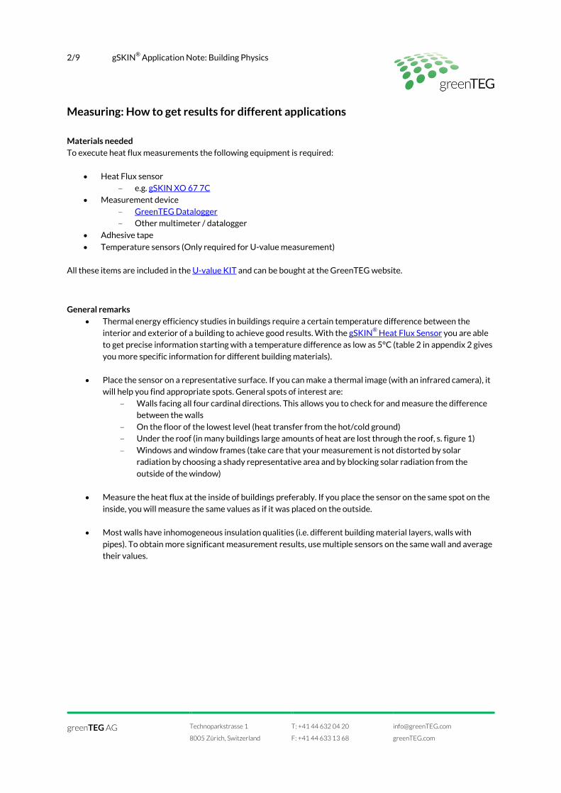
Why using a heat flux sensor A building is a complex thermal system. Thermal energy is
entering the building via the heating system and solar radiation. Energy leaks to the outside through the roof, walls, windows and
other various thermal bridges e.g. balconies, into the soil and through exchange to ambient air. To fully understand this
thermal system in order to optimize it (for example to reduce heating costs), precise data is required.
Use the gSKIN® Heat Flux Sensor to:
• Compare the amount of heat transferred through different walls
• Calculate the overall heat transfer coefficient (U-Value) of walls or windows and find out if you have a well-insulated building
• Quantify the energy balance of a room: How much
energy is coming from the heating and where is energy lost?
• Calculate energy provided by the heating radiator to
forecast for example your heating costs
• Optimize through enhanced insights your heating and
cooling control
• Analyze the thermal behavior of rooms / buildings at different temperature levels
Figure 1: Heat lost from a building on a Swiss winter day in % of total.
greenTEG AG
Technoparkstrasse 1
8005 Zürich, Switzerland
T: +41 44 632 04 20
F: +41 44 633 13 68
greenTEG.com
2/9 gSKIN® Application Note: Building Physics
Measuring: How to get results for different applications Materials needed To execute heat flux measurements the following equipment is required:
• Heat Flux sensor
- e.g. gSKIN XO 67 7C
• Measurement device
- GreenTEG Datalogger - Other multimeter / datalogger
• Adhesive tape
• Temperature sensors (Only required for U-value measurement)
All these items are included in the U-value KIT and can be bought at the GreenTEG website.
General remarks
• Thermal energy efficiency studies in buildings require a certain temperature difference between the
interior and exterior of a building to achieve good results. With the gSKIN® Heat Flux Sensor you are able to get precise information starting with a temperature difference as low as 5°C (table 2 in appendix 2 gives
you more specific information for different building materials).
• Place the sensor on a representative surface. If you can make a thermal image (with an infrared camera), it will help you find appropriate spots. General spots of interest are:
- Walls facing all four cardinal directions. This allows you to check for and measure the difference between the walls
- On the floor of the lowest level (heat transfer from the hot/cold ground) - Under the roof (in many buildings large amounts of heat are lost through the roof, s. figure 1)
- Windows and window frames (take care that your measurement is not distorted by solar radiation by choosing a shady representative area and by blocking solar radiation from the
outside of the window)
• Measure the heat flux at the inside of buildings preferably. If you place the sensor on the same spot on the
inside, you will measure the same values as if it was placed on the outside.
• Most walls have inhomogeneous insulation qualities (i.e. different building material layers, walls with
pipes). To obtain more significant measurement results, use multiple sensors on the same wall and average their values.
greenTEG AG
Technoparkstrasse 1
8005 Zürich, Switzerland
T: +41 44 632 04 20
F: +41 44 633 13 68
greenTEG.com
3/9 gSKIN® Application Note: Building Physics
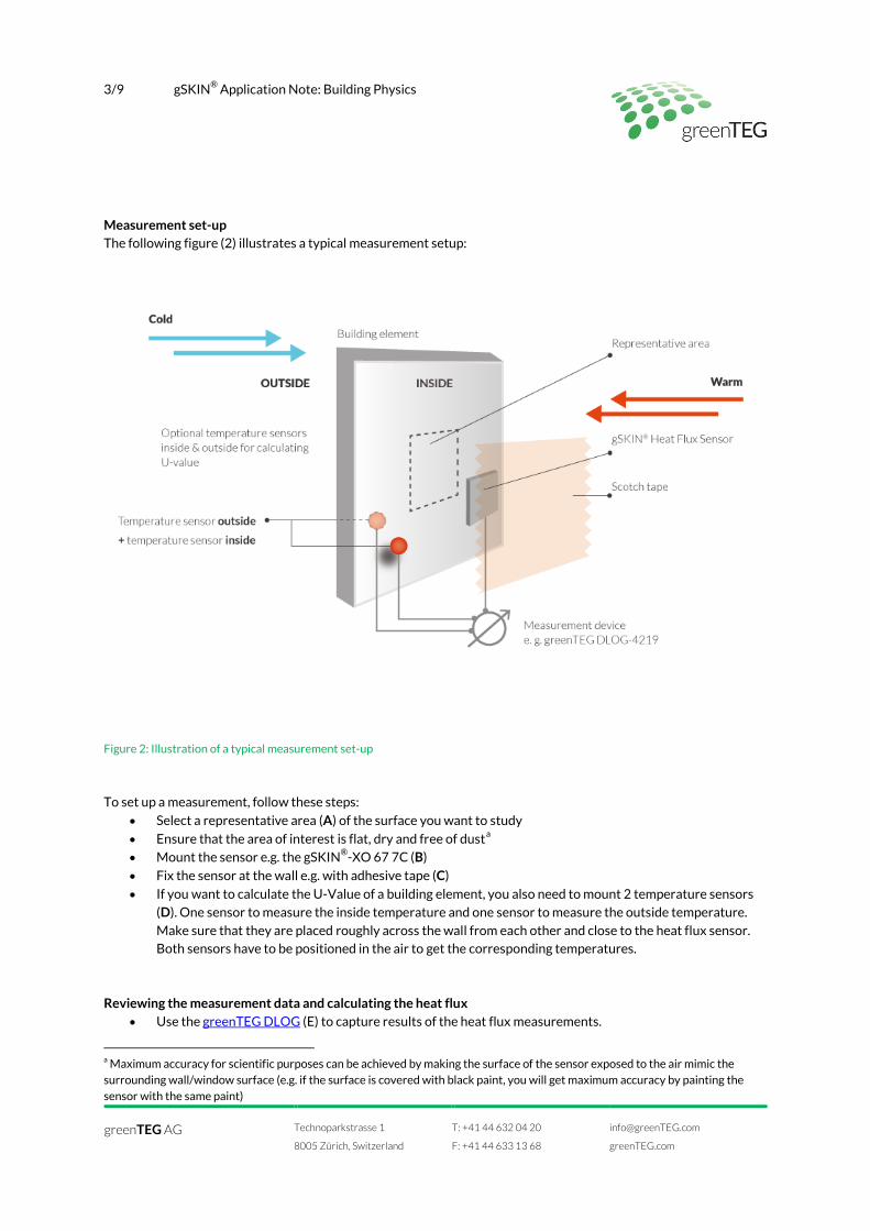
Measurement set-up The following figure (2) illustrates a typical measurement setup:
Figure 2: Illustration of a typical measurement set-up
To set up a measurement, follow these steps:
• Select a representative area (A) of the surface you want to study
• Ensure that the area of interest is flat, dry and free of dusta
• Mount the sensor e.g. the gSKIN®-XO 67 7C (B)
• Fix the sensor at the wall e.g. with adhesive tape (C)
• If you want to calculate the U-Value of a building element, you also need to mount 2 temperature sensors
(D). One sensor to measure the inside temperature and one sensor to measure the outside temperature.
Make sure that they are placed roughly across the wall from each other and close to the heat flux sensor. Both sensors have to be positioned in the air to get the corresponding temperatures.
Reviewing the measurement data and calculating the heat flux • Use the greenTEG DLOG (E) to capture results of the heat flux measurements.
a Maximum accuracy for scientific purposes can be achieved by making the surface of the sensor exposed to the air mimic the surrounding wall/window surface (e.g. if the surface is covered with black paint, you will get maximum accuracy by painting the sensor with the same paint)
greenTEG AG
Technoparkstrasse 1
8005 Zürich, Switzerland
T: +41 44 632 04 20
F: +41 44 633 13 68
greenTEG.com
4/9 gSKIN® Application Note: Building Physics
• If you use another data logger multimeter or other read-out device, make sure that your device has a
resolution of 1 µV or higher. Follow these instructions:
o Connect the gSKIN® Heat Flux Sensor to your measurement device and record the output voltage
U
o Calculate the heat flux φ using the sensor-specific sensitivity S (which is delivered with your
gSKIN® Heat Flux Sensor)
o The equation for calculating the heat flux is:
where
φ Heat Flux in W/m2
U measured voltage in V
S sensor-specific sensitivity in µV/(W/m2)
Interpretation of your measurement results
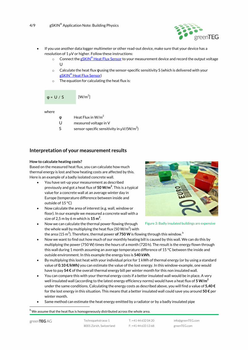
How to calculate heating costs? Based on the measured heat flux, you can calculate how much thermal energy is lost and how heating costs are affected by this.
Here is an example of a badly isolated concrete wall.
• You have set-up your measurement as described
previously and got a heat flux of 50 W/m2. This is a typical value for a concrete wall at an average winter day in
Europe (temperature difference between inside and outside of 15 °C)
• Now calculate the area of interest (e.g. wall, window or
floor). In our example we measured a concrete wall with a size of 2,5 m by 6 m which is 15 m2.
• Now we can calculate the thermal power flowing through
the whole wall by multiplying the heat flux (50 W/m2) with the area (15 m2). Therefore, thermal power of 750 W is flowing through this window.b
• Now we want to find out how much of our monthly heating bill is caused by this wall. We can do this by
multiplying the power (750 W) times the hours of a month (720 h). The result is the energy flown through this wall during 1 month assuming an average temperature difference of 15 °C between the inside and
outside environment. In this example the energy loss is 540 kWh.
• By multiplying this lost heat with your individual price for 1 kWh of thermal energy (or by using a standard
value of 0.10 €/kWh) you can estimate the value of the lost energy. In this window-example, one would have to pay 54 € of the overall thermal energy bill per winter month for this non insulated wall.
• You can compare this with your thermal energy costs if a better insulated wall would be in place. A very
well insulated wall (according to the latest energy efficiency norms) would have a heat flux of 5 W/m2
under the same conditions. Calculating the energy costs as described above, you will find a value of 5,40 € for the lost energy in this situation. This means that a better insulated wall could save you around 50 € per winter month.
• Same method can estimate the heat energy emitted by a radiator or by a badly insulated pipe
b We assume that the heat flux is homogeneously distributed across the whole area.
φ = U / S
[W/m2]
Figure 3: Badly insulated buildings are expensive
greenTEG AG
Technoparkstrasse 1
8005 Zürich, Switzerland
T: +41 44 632 04 20
F: +41 44 633 13 68
greenTEG.com
5/9 gSKIN® Application Note: Building Physics
Calculating the U-Value (requires two additional temperature sensors)c To measure the U-value directly, follow these steps:
• Set up the measurement with two additional temperature sensors as shown in Figure 2. The greenTEG
DLOG (E) calculates the U-value directly based on the measured heat flux and the measured temperatures.
• The U-value can also be calculated manually with
the following equation:
where U-Value overall heat transfer coefficient in W/(m2K)
φ mean value of all heat flux data points in W/m2
ΔT mean value of all temperature difference data points in °C
• Table 1 in appendix 2 lists some typical values for building materials and gives you an indication for the
quality of building materials. It also shows typical heat flux values and minimum temperature difference for which heat flux values can be resolved with the gSKIN®-XO 67 7C. Further example values are stated for
how much thermal energy is lost with a temperature difference of 10°C for the specific material for a given winter month.
c For a detailed description of U-Value measurements and evaluation, refer to greenTEG’s U-Value case study.
U-Value = φ / ΔT
[ W/(m2K)]
greenTEG AG
Technoparkstrasse 1
8005 Zürich, Switzerland
T: +41 44 632 04 20
F: +41 44 633 13 68
greenTEG.com
6/9 gSKIN® Application Note: Building Physics
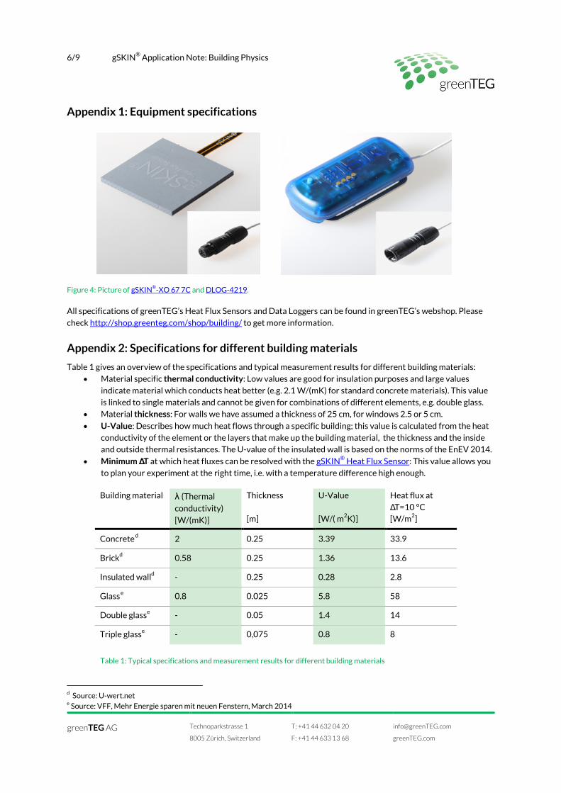
Appendix 1: Equipment specifications
Figure 4: Picture of gSKIN®-XO 67 7C and DLOG-4219. All specifications of greenTEG’s Heat Flux Sensors and Data Loggers can be found in greenTEG’s webshop. Please
check http://shop.greenteg.com/shop/building/ to get more information.
Appendix 2: Specifications for different building materials
Table 1 gives an overview of the specifications and typical measurement results for different building materials:
• Material specific thermal conductivity: Low values are good for insulation purposes and large values
indicate material which conducts heat better (e.g. 2.1 W/(mK) for standard concrete materials). This value
is linked to single materials and cannot be given for combinations of different elements, e.g. double glass.
• Material thickness: For walls we have assumed a thickness of 25 cm, for windows 2.5 or 5 cm.
• U-Value: Describes how much heat flows through a specific building; this value is calculated from the heat
conductivity of the element or the layers that make up the building material, the thickness and the inside and outside thermal resistances. The U-value of the insulated wall is based on the norms of the EnEV 2014.
• Minimum ΔT at which heat fluxes can be resolved with the gSKIN® Heat Flux Sensor: This value allows you
to plan your experiment at the right time, i.e. with a temperature difference high enough.
Building material λ (Thermal
conductivity)
[W/(mK)]
Thickness
[m]
U-Value
[W/( m2K)]
Heat flux at
ΔT=10 °C [W/m2]
Concreted 2 0.25 3.39 33.9
Brickd 0.58 0.25 1.36 13.6
Insulated walld - 0.25 0.28 2.8
Glasse 0.8 0.025 5.8 58
Double glasse - 0.05 1.4 14
Triple glasse - 0,075 0.8 8
Table 1: Typical specifications and measurement results for different building materials
d Source: U-wert.net e Source: VFF, Mehr Energie sparen mit neuen Fenstern, March 2014
greenTEG AG
Technoparkstrasse 1
8005 Zürich, Switzerland
T: +41 44 632 04 20
F: +41 44 633 13 68
greenTEG.com
7/9 gSKIN® Application Note: Building Physics
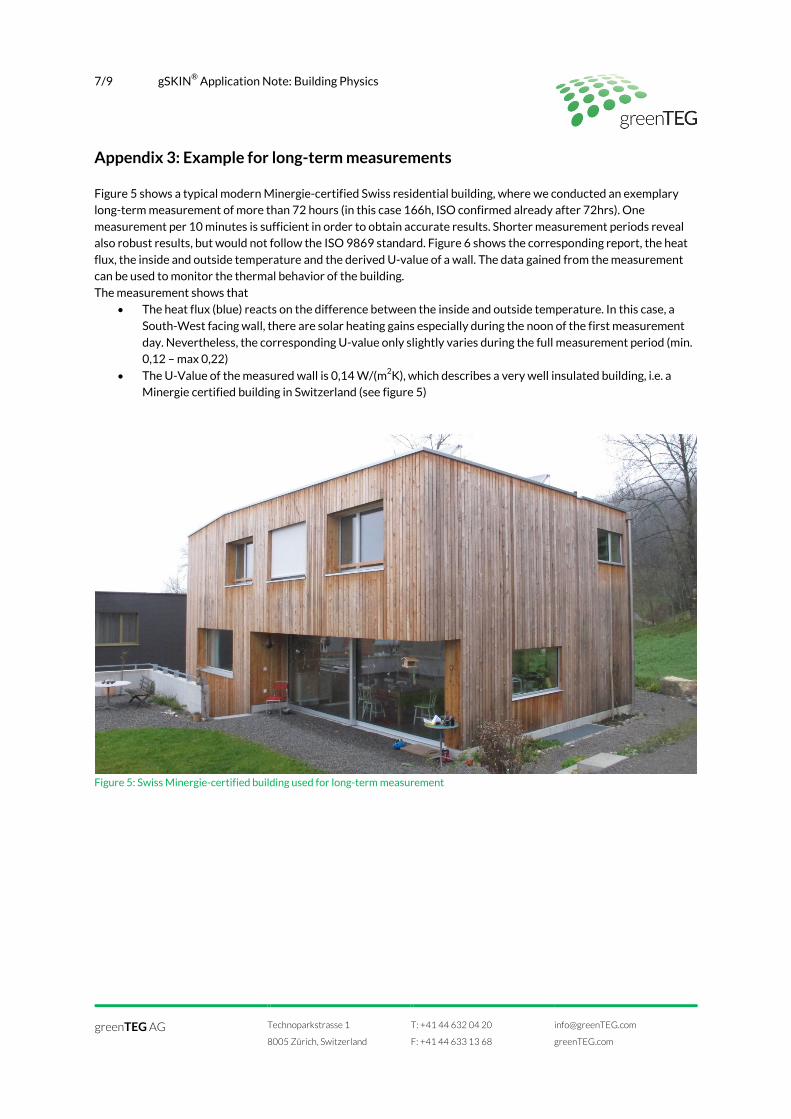
Appendix 3: Example for long-term measurements
Figure 5 shows a typical modern Minergie-certified Swiss residential building, where we conducted an exemplary long-term measurement of more than 72 hours (in this case 166h, ISO confirmed already after 72hrs). One
measurement per 10 minutes is sufficient in order to obtain accurate results. Shorter measurement periods reveal also robust results, but would not follow the ISO 9869 standard. Figure 6 shows the corresponding report, the heat
flux, the inside and outside temperature and the derived U-value of a wall. The data gained from the measurement can be used to monitor the thermal behavior of the building.
The measurement shows that
• The heat flux (blue) reacts on the difference between the inside and outside temperature. In this case, a
South-West facing wall, there are solar heating gains especially during the noon of the first measurement
day. Nevertheless, the corresponding U-value only slightly varies during the full measurement period (min. 0,12 – max 0,22)
• The U-Value of the measured wall is 0,14 W/(m2K), which describes a very well insulated building, i.e. a Minergie certified building in Switzerland (see figure 5)
Figure 5: Swiss Minergie-certified building used for long-term measurement
greenTEG AG
Technoparkstrasse 1
8005 Zürich, Switzerland
T: +41 44 632 04 20
F: +41 44 633 13 68
greenTEG.com

8/9 gSKIN® Application Note: Building Physics
Figure 6: Heat flux, inside and outside temperature and U-Value measurement on a wall of a typical modern Minergie-certified Swiss residential building. The figure was created using the software included in all U-Value Kits
greenTEG AG
Technoparkstrasse 1
8005 Zürich, Switzerland
T: +41 44 632 04 20
F: +41 44 633 13 68
greenTEG.com

9/9 gSKIN® Application Note: Building Physics
Disclaimer
The above restrictions, recommendations, materials, etc. do not cover all possible cases and items. This document is not to be considered to be complete and it is subject to change without prior notice.
Document information
Copyright © greenTEG AG, All rights reserved Pictures by greenTEG AG and flickr
Revision History
Date Revision Changes
5. April 2013 0.1 (preliminary) Initial version
17. May 2013 1.0 (first published) Completed content
9. July 2013 1.6 Revised tables
12. August 2013 1.7 Measurement data added
11. February 2014 12. December 2014
2.5 2.6
Revision of symbols, figures and tables New software report figures, general updates
4 February 2015 2.7 Revision Heat flux calculations, general updates
greenTEG AG
Technoparkstrasse 1
8005 Zürich, Switzerland
T: +41 44 632 04 20
F: +41 44 633 13 68
greenTEG.com