grounding systems grounding systems. the objective of a grounding system are: 1. to provide safety...
TRANSCRIPT
GROUNDING SYSTEMSGROUNDING SYSTEMS
The objective of a grounding system are:
1. To provide safety to personnel during normal and fault conditions by limiting step and touch potential.
2. To assure correct operation of electrical/electronic devices.
3. To prevent damage to electrical/electronic apparatus.
4. To dissipate lightning strokes.
5. To stabilize voltage during transient conditions and to minimize the probability of flashover during transients.
6. To divert stray RF energy from sensitive audio, video, control, and computer equipment.
A safe grounding design has two objectives:
1. To provide means to carry electric currents into the earth under normal and fault conditions without exceeding any operating and equipment limits or adversely affecting continuity of service.
2. To assure that a person in the vicinity of grounded facilities is not exposed to the danger of critical electric shock.
The PRIMARY goal of the grounding
system throughout any facilities is
SAFETY.
Why ground at all?
PERSONNEL SAFETY FIRST
EQUIPMENT PROTECTION SECOND
The three main types are: EQUIPMENT GROUNDING (SAFETY) SYSTEM GROUNDING LIGHTNING/SURGE GROUNDING
What are the three main typesof grounding?

Types of Grounding Systems
Ground rod
Earth / Ground BasicsEarth / Ground Basics
Many different types availableMany different types available Choice depends on local Choice depends on local
conditions and required conditions and required functionfunction
Simplest form is a single Simplest form is a single stakestake
Mostly used for:Mostly used for: Lightning protectionLightning protection Stand alone structuresStand alone structures Back-up for utility groundBack-up for utility ground

Types of Grounding Systems
Ground rod group
Earth / Ground BasicsEarth / Ground Basics
ground rod groupground rod group
typically for lightning typically for lightning protection on larger protection on larger structures or protection structures or protection around potential hotspots around potential hotspots such as substations.such as substations.
Types of Grounding Systems
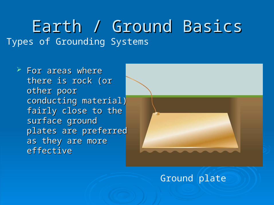
Ground plate
Earth / Ground BasicsEarth / Ground Basics
For areas where there is For areas where there is rock (or other poor rock (or other poor conducting material) fairly conducting material) fairly close to the surface ground close to the surface ground plates are preferred as plates are preferred as they are more effectivethey are more effective
Types of Grounding Systems
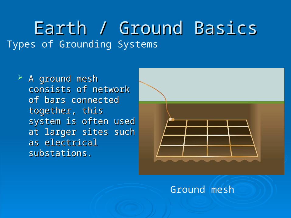
Ground mesh
Earth / Ground BasicsEarth / Ground Basics
A ground mesh consists of A ground mesh consists of network of bars connected network of bars connected together, this system is together, this system is often used at larger sites often used at larger sites such as electrical such as electrical substations.substations.

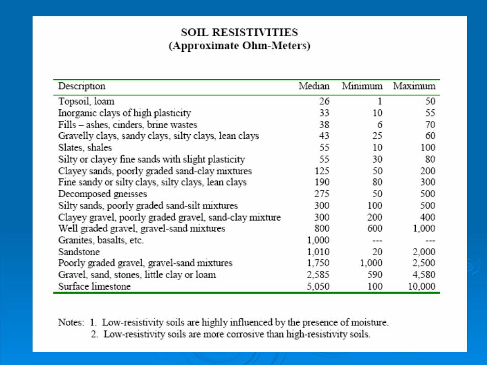
Soil CharacteristicsSoil Characteristics Soil typeSoil type. Soil resistivity varies widely . Soil resistivity varies widely
depending on soil type, from as low as depending on soil type, from as low as 1 1 Ohmmeter for moistOhmmeter for moist loamy topsoil to almost loamy topsoil to almost 10,000 Ohm-meters10,000 Ohm-meters for for surface limestonesurface limestone..
Moisture content Moisture content is one of the controlling is one of the controlling factors in earth resistance because electrical factors in earth resistance because electrical conduction in soil is essentially electrolytic. conduction in soil is essentially electrolytic.
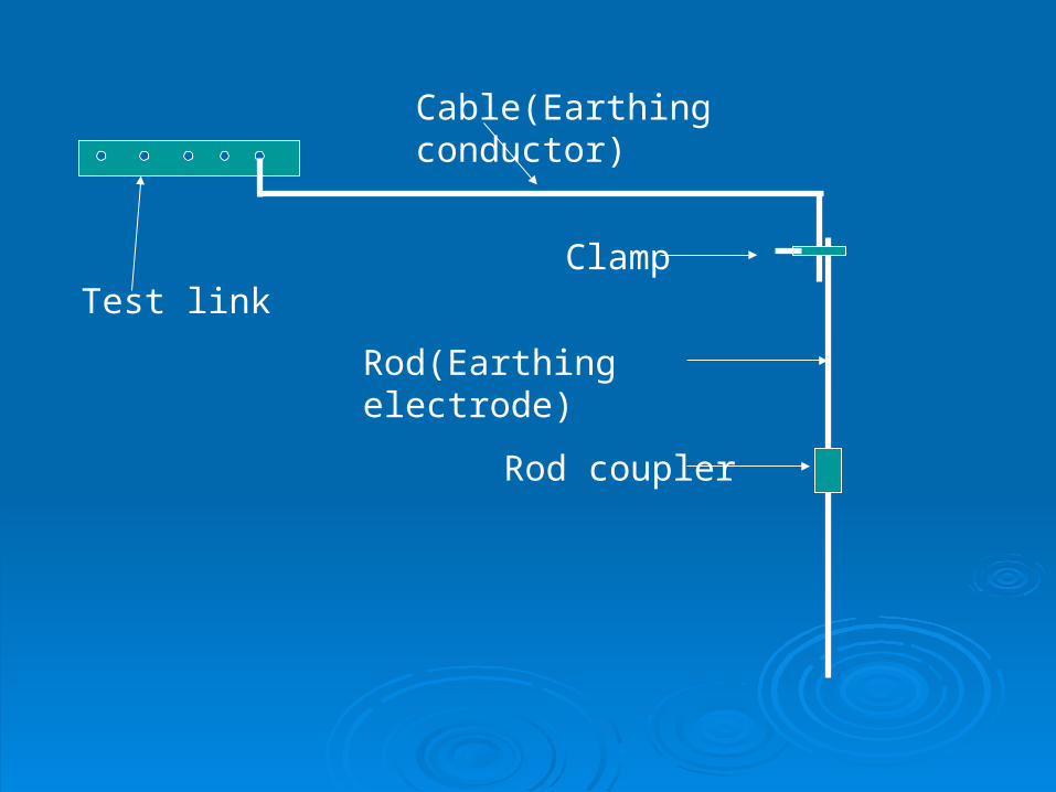
Test link
Cable(Earthing conductor)
Clamp
Rod(Earthing electrode)
Rod coupler

Recommended values of earth resistance
systemsystem Recommended earth Recommended earth resistance(ohm)resistance(ohm)
Light current Light current 0.5-10.5-1
Low voltage Low voltage 55
Medium Medium voltagevoltage
2.52.5
High voltageHigh voltage 0.5 0.5
Substation earthing system
•Step & Touch voltage
•Grounding grids
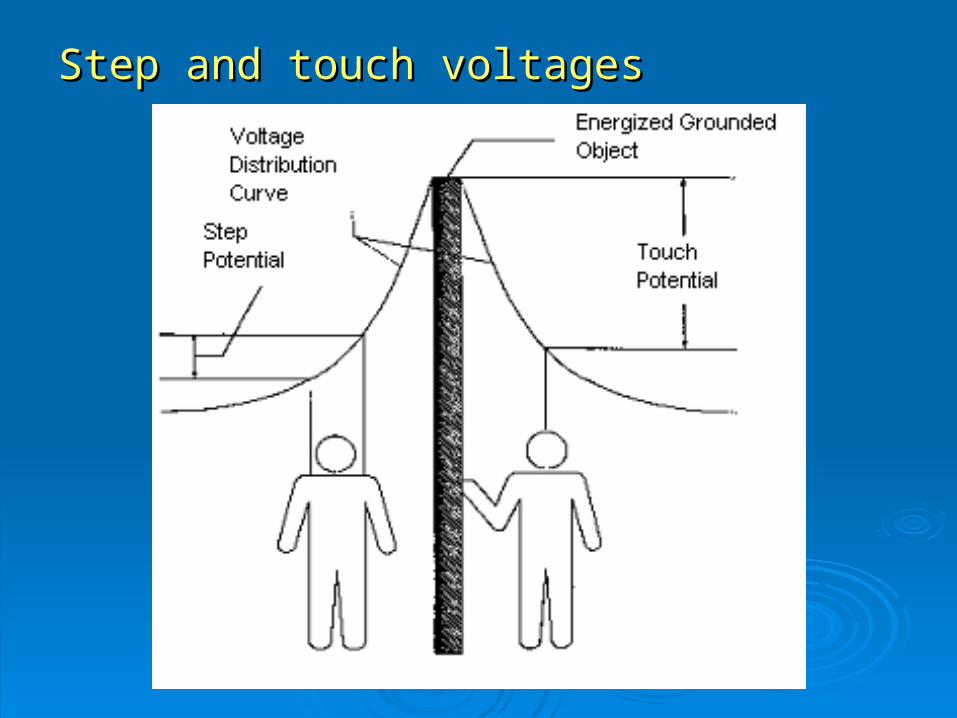
Step and touch voltagesStep and touch voltages
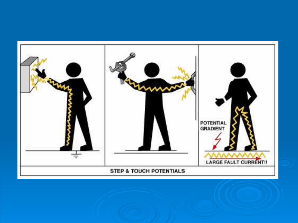

Step potentialStep potential “ “Step potential” is the voltage Step potential” is the voltage
between the feet of a person standing between the feet of a person standing near an energized grounded object. near an energized grounded object.
It is equal to the difference in voltage, It is equal to the difference in voltage, given by the voltage distribution curve, given by the voltage distribution curve, between two points at different between two points at different distances from the “electrode.” distances from the “electrode.”
A person could be at risk of injury A person could be at risk of injury during a fault simply by standing near during a fault simply by standing near the grounding point.the grounding point.
Touch potentialTouch potential “ “Touch potential” is the voltage between Touch potential” is the voltage between
the energized object and the feet of a the energized object and the feet of a person in contact with the object. person in contact with the object.
It is equal to the difference in voltage It is equal to the difference in voltage between the energized object and a point between the energized object and a point some distance away. some distance away.
The touch potential could be nearly the The touch potential could be nearly the full voltage across the grounded object if full voltage across the grounded object if that object is grounded at a point remote that object is grounded at a point remote from the place where the person is in from the place where the person is in contact with it.contact with it.
Resistivity Measurement
The purpose of resistivity measurements is to quantify the effectiveness of the earth where a grounding system will be installed.
Differing earth materials will affect the effectiveness of the grounding system.
The capability of different earth materials to conduct current can be quantified by the value E (resistivity in .m).
Resistivity measurements should be made prior to installing a grounding system, the values measured will have an effect on the design of the grounding system.
Ground Testing Methods (1)Ground Testing Methods (1)

Resistivity Measurement ( Wenner method)
Resistivity measurements are performed by using a Resistivity measurements are performed by using a four wire methodfour wire method.
Used to determine which KIND of earthing should be used, so BEFORE placing earth stakes
Ground Testing Ground Testing Methods (1)Methods (1)
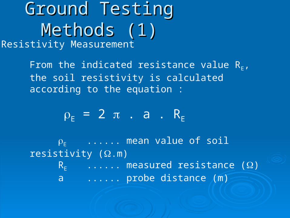
Resistivity Measurement
From the indicated resistance value RE, the soil resistivity is calculated according to the equation :
E = 2 . a . RE
E ...... mean value of soil resistivity (.m)RE ...... measured resistance ()a ...... probe distance (m)
Ground Testing Ground Testing Methods (1)Methods (1)
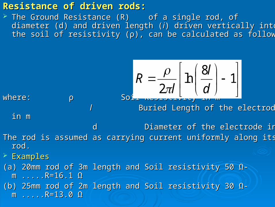
Resistance of driven rods:Resistance of driven rods: The Ground Resistance (R) of a single rod, of diameter (d) and The Ground Resistance (R) of a single rod, of diameter (d) and
driven length (driven length (ii) driven vertically into the soil of resistivity (ρ), can ) driven vertically into the soil of resistivity (ρ), can be calculated as followsbe calculated as follows::
where: ρ Soil Resistivity in mwhere: ρ Soil Resistivity in m l l Buried Length of the electrode in m Buried Length of the electrode in m d Diameter of the electrode in md Diameter of the electrode in mThe rod is assumed as carrying current uniformly along its rod.The rod is assumed as carrying current uniformly along its rod. ExamplesExamples(a) 20mm rod of 3m length and Soil resistivity 50 Ω-m .....R=16.1 Ω(a) 20mm rod of 3m length and Soil resistivity 50 Ω-m .....R=16.1 Ω(b) 25mm rod of 2m length and Soil resistivity 30 Ω-m .....R=13.0 Ω(b) 25mm rod of 2m length and Soil resistivity 30 Ω-m .....R=13.0 Ω
1
8ln
2 d
l
lR
The resistance of a single rod is not sufficiently The resistance of a single rod is not sufficiently low.low.
A number of rods are connected in parallel.A number of rods are connected in parallel. They should be driven far apart as possible to They should be driven far apart as possible to
minimize the overlap among their areas of minimize the overlap among their areas of influence.influence.
It is necessary to determine the net reduction in It is necessary to determine the net reduction in the total resistance by connecting rods in the total resistance by connecting rods in parallel.parallel.
The rod is replaced by a hemispherical The rod is replaced by a hemispherical electrode having the same resistance.electrode having the same resistance.
Rod Electrodes in ParallelRod Electrodes in Parallel
If the desired ground resistance cannot be If the desired ground resistance cannot be achieved with one ground electrode, the overall achieved with one ground electrode, the overall resistance can be reduced by connecting a resistance can be reduced by connecting a number of electrodes in parallel. number of electrodes in parallel.
These are called “arrays of rod electrodes”.These are called “arrays of rod electrodes”.
The combined resistance is a function of the The combined resistance is a function of the number and configuration of electrodes, the number and configuration of electrodes, the separation between them, their dimensions and separation between them, their dimensions and soil resistivity. soil resistivity.
Rods in parallel should be spaced at least twice Rods in parallel should be spaced at least twice their length to utilize the full benefit of the their length to utilize the full benefit of the additional rods.additional rods.
If the separation of the electrodes is much If the separation of the electrodes is much larger than their lengths and only a few larger than their lengths and only a few electrodes are in parallel, then the resultant electrodes are in parallel, then the resultant ground resistance can be calculated using the ground resistance can be calculated using the ordinary equation for resistances in parallel. ordinary equation for resistances in parallel.
In practice, the effective ground resistance will In practice, the effective ground resistance will usually be higher than this. usually be higher than this.
Typically, a 4 spike array may provide an Typically, a 4 spike array may provide an improvement of about 2.5 to 3 times. improvement of about 2.5 to 3 times.
An 8 spike array will typically give an An 8 spike array will typically give an improvement of may be 5 to 6 times.improvement of may be 5 to 6 times.

Earth clamping 1
AT-090H
AT-090H
Earth clamping 2
AT-087J AT-089J AT-093J

METHODS OF DECREASING GROUND METHODS OF DECREASING GROUND RESISTANCERESISTANCE
Decreasing the ground resistance of a Decreasing the ground resistance of a grounding system in high resistivity soil is grounding system in high resistivity soil is often a formidable task. often a formidable task.
Recently, some new methods have been Recently, some new methods have been proposed to decrease ground resistance. proposed to decrease ground resistance.
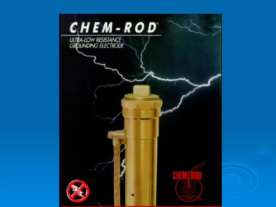
1-Chemical Rods 1-Chemical Rods
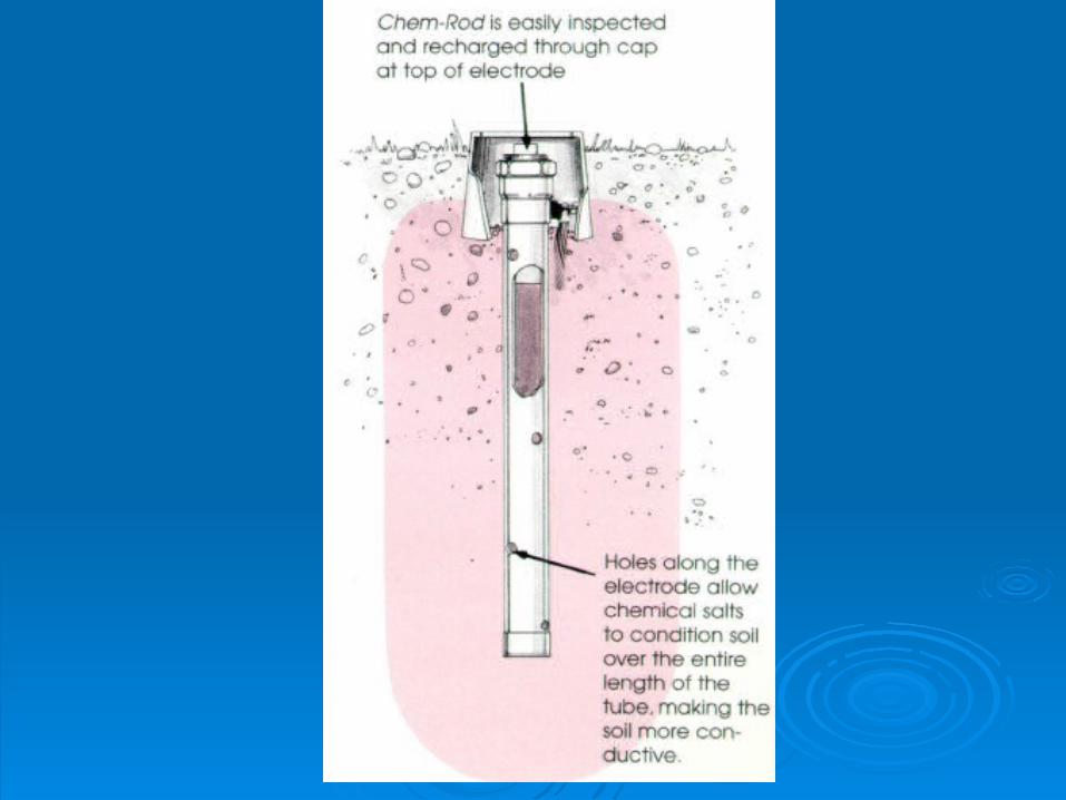
Chemical rods are electrodes with holes along Chemical rods are electrodes with holes along their length, filled with mineral salts. their length, filled with mineral salts.
The specially formulated mineral salts are evenly The specially formulated mineral salts are evenly distributed along the entire length of the distributed along the entire length of the electrode.electrode.
The rod absorbs moisture from both air and soil. The rod absorbs moisture from both air and soil. Continuous conditioning of a large area insures Continuous conditioning of a large area insures
an ultra-low-resistance ground which is more an ultra-low-resistance ground which is more effective than a conventional electrode. effective than a conventional electrode.
If the conductive salts are running low, the If the conductive salts are running low, the rod can be recharged with a refill kit.rod can be recharged with a refill kit.
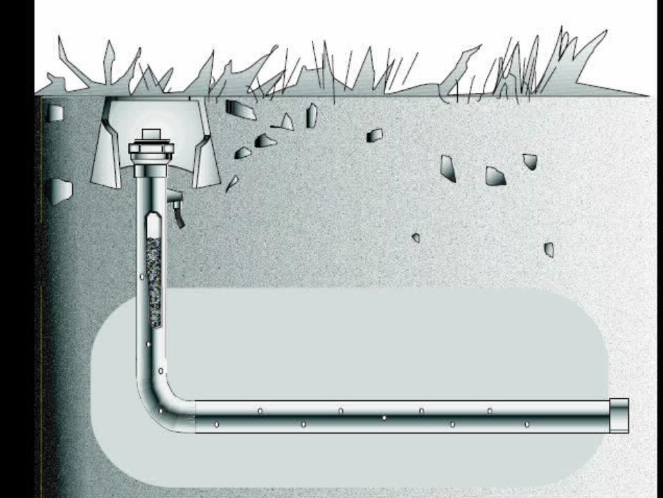
These rods are available in vertical and These rods are available in vertical and horizontal configurations. horizontal configurations.
They may be used in rocky soils, freezing They may be used in rocky soils, freezing climates, dry deserts, or tropical rain climates, dry deserts, or tropical rain forests. forests.
They provide stable protection for many They provide stable protection for many years. years.


Disadvantages are: Chemicals concentrated around
electrodes will cause corrosion Chemicals leach through the soil and
dissipate Scheduled replacement may be required May be prohibited because they may
contaminate the water table
Soil Treatment Alternatives Ground enhancement material
Cement-like compound Non-corrosive Extremely conductive Installed around the electrode Easy installation Permanent
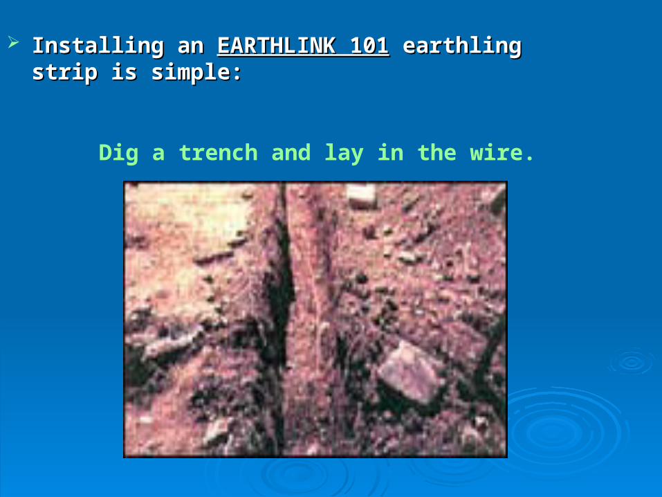
Installing an Installing an EARTHLINK 101EARTHLINK 101 earthling strip is earthling strip is simple:simple:
Dig a trench and lay in the wire.
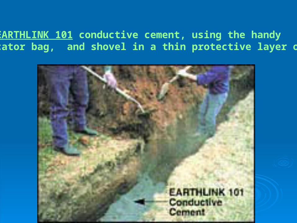
Pour EARTHLINK 101 conductive cement, using the handyapplicator bag, and shovel in a thin protective layer of soil.
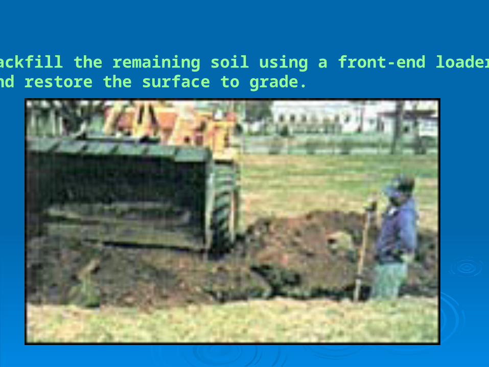
Backfill the remaining soil using a front-end loader and restore the surface to grade.