grounding basics: mobile systems - diysolarforum.com
TRANSCRIPT

The subject of grounding is a complex, multifaceted subject, that is often treated as an after-thought but needs to be considered from the beginning of the design and build process of any DIY Solar/Battery Project.
This is Part 4 of a 4-part series on grounding Basics.
1. AC & HouseholdPart 1 covers the basics of grounding for household AC systems. Even if you are familiar with house wiring, it is suggested that the reader review this paper to become familiar with the terminology concepts and practices of grounding.
2. Stationary SystemsPart 2 introduces the grounding principles of DC wiring, inverters and multiple power sources.
3. Solar PanelsPart 3 is a short overview of how to properly ground the frames and mounting racks of Solar arrays.
4. Mobile Systems (This Paper)Part 4 goes through designing the grounding scheme that addresses the unique situations encountered in a mobile system.
Each of the 4 parts are written to be usable and understandable as a stand-alone paper. However, to get a broad understanding of grounding and grounding principles, it is recommended that all 4 papers be read.
Grounding Basics: Mobile SystemsGrounding Made Simple

Document Structure.For this document we will go through the process of designing a vehicle mounted system in this order:1) House battery 2) DC Loads, 3) Solar and Solar Charge Controller, 4) Inverter, 5) Shore power 6) Generator7) DC-DC charger for charging off the vehicle Inverter.
At each stage we will discuss the design details as it relates to grounding but will not go into system details not related to grounding.
Note: Much of this document is also applicable to a marine system, but there are some marine specific issues that will not be covered.

1) Battery and Ground
The first step in grounding a LiFePO4 set-up for a mobile system is tying the DC circuit to ground. For mobile systems, the vehicle is on rubber tires so there is no earth ground. Instead, we use vehicle chassis as our proxy for earth Ground
Why tie Negative to Chassis?The primary reason to tie Negative to chassis is to prevent an imposed charge from creating large voltage differences between the system and the rest of the vehicle. This may seem unlikely but think of the last time you received a static Shock. The voltage of the shock was quite high, and it is possible for it to damage electronics. Furthermore, in an electrical storm, the chassis can develop a significantly different charge level than the DC circuit if the Chassis is not bonded to the DC circuit.
NOTE 1) The Tie between chassis and DC negative should only be done at one place. Otherwise, ground loops can develop and create difficult RFI issues. It is best to have a separate Grounding Bus Bar that will be used for multiple grounding connections. In simple systems, the grounding busbar and negative
busbar can be one and the same, but as a best practice especially for more complex systems or if you are unsure which approach is right
for you, a dedicated grounding busbar is preferable
Note 2) Most mobile systems will be 12 or 24 volt, but occasionally a mobile 48 volt system will be built. The concepts around grounding are Identical for any voltage. However, the NEC makes earth grounding 48 volt (nominal) circuits mandatory while grounding 12 or 24 Volt circuits is optional but recommended. (For mobile, systems, this would be Chassis ground) Furthermore, if the Solar Array can operate above 50V the NEC requires the DC circuit to be [Chassis] grounded. My personal recommendation is to always bond DC negative to chassis.
Note 3) The NEC allows tying either positive or negative to ground/chassis (not both). However, the only time a vehicle mounted system would do this is if the vehicle is an older, positive grounded vehicle (Very rare these days)
HouseBattery
Loads
Chassis
Fuse
Common Grounding Bus bar
Common Negative Bus bar

Bond DC circuits to the ground point after the BMS
Most FET based BMSs are positioned in series with the most-negative cell of the battery bank. In this case the DC negative to equipment ground bond should not be between the battery and BMS.
75A Load
7.5A Load
10
10
0
16 AWG Wire
BMS
Short to Chassis
Fuse
s
75A
Battery
Fuse
The figure to the right shows both a safety issue and a functional issue with bonding DC neg to ground between the BMS and the Battery.
1. Safety Issue: High current short.If the BMS disconnects the battery, a short to ground on a small wire could cause a large amount of current that the fuses would not stopand the wire can not handle. This is a significant fire safety issue.
2. Functional Issue: BMS can not turn off current in a short scenario.Even if the short did not cause a fire, it is allowing current to flow even though the BMS has tried to turn it off. This circumvents the cell protection offered by the BMS.
3. Functional issue: Chassis as return.A third issue (not shown) is that in a mobile system, people often use chassis as a negative return conductor. If this is done and the bond is between the battery and BMS, the BMS can not shut off the current.
Do not bond to chassis between the BMS and the Battery
DC System Grounding Conductor should be attached here
Chassis ground
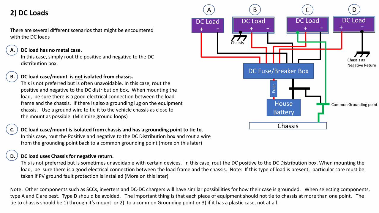
DC Load2) DC Loads
There are several different scenarios that might be encountered with the DC loads
A. DC load has no metal case. In this case, simply rout the positive and negative to the DC distribution box.
B. DC load case/mount is not isolated from chassis. This is not preferred but is often unavoidable. In this case, rout the positive and negative to the DC distribution box. When mounting the load, be sure there is a good electrical connection between the load frame and the chassis. If there is also a grounding lug on the equipmentchassis. Use a ground wire to tie it to the vehicle chassis as close to the mount as possible. (Minimize ground loops)
C. DC load case/mount is isolated from chassis and has a grounding point to tie to. In this case, rout the Positive and negative to the DC Distribution box and rout a wire from the grounding point back to a common grounding point (more on this later)
D. DC load uses Chassis for negative return. This is not preferred but is sometimes unavoidable with certain devices. In this case, rout the DC positive to the DC Distribution box. When mounting the load, be sure there is a good electrical connection between the load frame and the chassis. Note: If this type of load is present, particular care must be taken if PV ground fault protection is installed (More on this later)
Note: Other components such as SCCs, inverters and DC-DC chargers will have similar possibilities for how their case is grounded. When selecting components, type A and C are best. Type D should be avoided. The important thing is that each piece of equipment should not tie to chassis at more than one point. The tie to chassis should be 1) through it’s mount or 2) to a common Grounding point or 3) if it has a plastic case, not at all.
DC LoadDC Load
HouseBattery
Chassis
Fuse
DC Load+ -
DC Load+ -
DC Load+ -
DC Load+ -
A B C D
DC Fuse/Breaker Box
Common Grounding point
Chassis as Negative Return
Chassis

3) Solar Panels and Solar Charge Controller.
• If the SCC has a metal Chassis, it should be solidly tied to the grounding system. If possible, it is best to ground it at the common grounding bus but it may be impractical to isolate the SCC Chassis from vehicle Chassis when mounting the SCC. If it is bonded to chassis at the mount, do not also run a ground wire to the DC Grounding bus bar.
• The metal frames and metal mounting racks for the panels are highly susceptible to static charges and should always have a strong electrical tie to chassis.
• If the panels and mounts are electrically isolated from the chassis, you would run a grounding wire from the Panels and mounts to the common DC grounding point. (Figure 1)
• If, the panels are mounted on a metal roof, there is probably already an electrical connection to chassis. In this case you would *not* run a second grounding wire to the common DC grounding bus (It would create ground loops). Instead, you would ensure the existing connection is solid. (Figure 2)
• For more on Solar Panel grounding and how to make solid connections to the panel frames, see the resource “Solar Panel Grounding”https://diysolarforum.com/resources/grounding-made-simpler-part-3-solar-panels.160/
• If a ground-Breaker style PV Ground Fault Protection Device (GFPD) is used, the PV negative path to ground must go through the GFPD (Figure 3). For more on PV Ground Fault Protection see the resource “Ground Fault Protection On Solar Panel Arrays.”: https://diysolarforum.com/resources/ground-fault-protection-on-solar-panel-arrays.147/
SCC
HouseBattery
DC Fuse Box
DC Grounding bus
DC Loads
FUS
E
FUS
E
SCC
Panels
Chassis
Figure 1 Figure 3
SCC
HouseBattery
DC Fuse Box
DC Grounding bus
DC Loads
FUS
E
FUS
ESCC
Panels
Chassis
Figure 2
Chassis SCC
HouseBattery
DC Grounding bus
DC Fuse Box
DC Loads
FUS
E
Panels
Chassis
FUS
E
GFPD
SCC
Note that DC is grounded through the GFPD
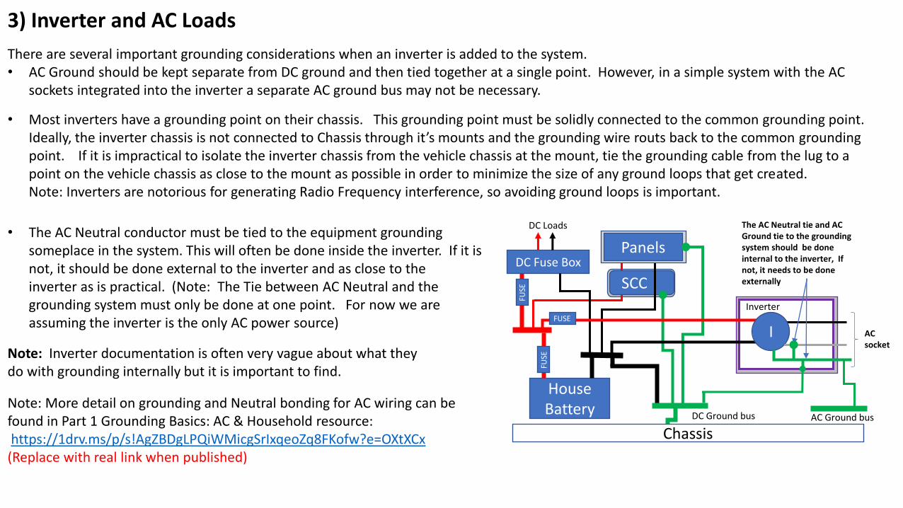
3) Inverter and AC Loads
There are several important grounding considerations when an inverter is added to the system.• AC Ground should be kept separate from DC ground and then tied together at a single point. However, in a simple system with the AC
sockets integrated into the inverter a separate AC ground bus may not be necessary.
• Most inverters have a grounding point on their chassis. This grounding point must be solidly connected to the common grounding point. Ideally, the inverter chassis is not connected to Chassis through it’s mounts and the grounding wire routs back to the common grounding point. If it is impractical to isolate the inverter chassis from the vehicle chassis at the mount, tie the grounding cable from the lug to a point on the vehicle chassis as close to the mount as possible in order to minimize the size of any ground loops that get created. Note: Inverters are notorious for generating Radio Frequency interference, so avoiding ground loops is important.
• The AC Neutral conductor must be tied to the equipment groundingsomeplace in the system. This will often be done inside the inverter. If it is not, it should be done external to the inverter and as close to the inverter as is practical. (Note: The Tie between AC Neutral and the grounding system must only be done at one point. For now we are assuming the inverter is the only AC power source)
Note: Inverter documentation is often very vague about what theydo with grounding internally but it is important to find.
Note: More detail on grounding and Neutral bonding for AC wiring can be found in Part 1 Grounding Basics: AC & Household resource:https://1drv.ms/p/s!AgZBDgLPQiWMicgSrIxqeoZq8FKofw?e=OXtXCx(Replace with real link when published)
SCC
HouseBattery
DC Fuse Box
DC Ground bus bus
DC Loads
FUSE
FUSE SCC
Panels
Chassis
FUSE
The AC Neutral tie and AC Ground tie to the grounding system should be done internal to the inverter, If not, it needs to be done externally
AC socket
AC Ground bus
I
Inverter

A note about Inverter Grounding similarities and differences.
Unfortunately, different inverters can handle ground differently so there can be no simple statement on how to handle grounding for all inverters.
Of the inverters I have looked at, the commonalities I have seen are:• They all have a case grounding lug• They all tie the AC-out Equipment Grounding Conductor to the case.• Inverters that have an AC in (Such as inverter-Chargers) all tie the AC-in Equipment Grounding Conductor to the case.Warning: The above are my observations of several different inverters and inverter brands. There is no guarantee all inverters will be the same.
However, there are several critical differences between inverters.• Most Inverters have a bond between AC Neutral and Ground. Some don’t.• Most inverters that have AC-in will dynamically switch on a N-G bond only when they are not getting power from the AC-
IN. Some don’t.
Note: Some all-in-one inverter products have built in Ground-fault protection. Be sure to read the manual carefully because these units may already tie the DC circuit to the grounding system and an additional connection between the DC and Ground system may create problems.
It is important to find out how your specific inverter handles all of this in order to set the system up correctly. Unfortunately, the manuals and spec sheets for many inverters do not describe what the inverter does so it can be difficult to find out.
The following resource on the DIY Solar Forum shows the best available information on how several popular inverters handle ground internally.https://diysolarforum.com/resources/grounding-details-for-specific-make-model-of-inverters.156/

SCC
4) Shore Power (with Transfer Switch.)
It is important that AC Neutral be tied to the grounding system at only one point. Furthermore, it must be assumed that any shore power system already has a tie between AC Neutral and ground. Consequently, when hooked to shore power the vehicle can NOT have a tie between AC neutral and ground but when not on shore power, it must have the tie. Therefore, the transfer switch must switch both AC Hot and AC Neutral.
Notice that the Ground line for shore power is NOT switched. Furthermore, when plugged into shore power, the grounding system is tied to earth ground.
In order to plug this circuit into a generator instead of shore power, the generator must have a neutral-ground bond. Most portable gas generators sold in the US do not have the Neutral-ground bond but they can be modified to have it.
HouseBattery
DC Fuse Box
DC Grounding Bus Bar
DC Loads
FUSE
FUSE SCC
Panels
Chassis
In this example the inverter ties AC Ground to neutral and it’s chassis. In this example, the tie between AC and DC ground is through the inverter chassis
Transfer Switch
ad
Sub Panel
No tie from Neutral to grounding system in the ACDistribution box
AC Circuits
Shore Power
I
Inverter
AC Grounding Bus Bar
FUSE
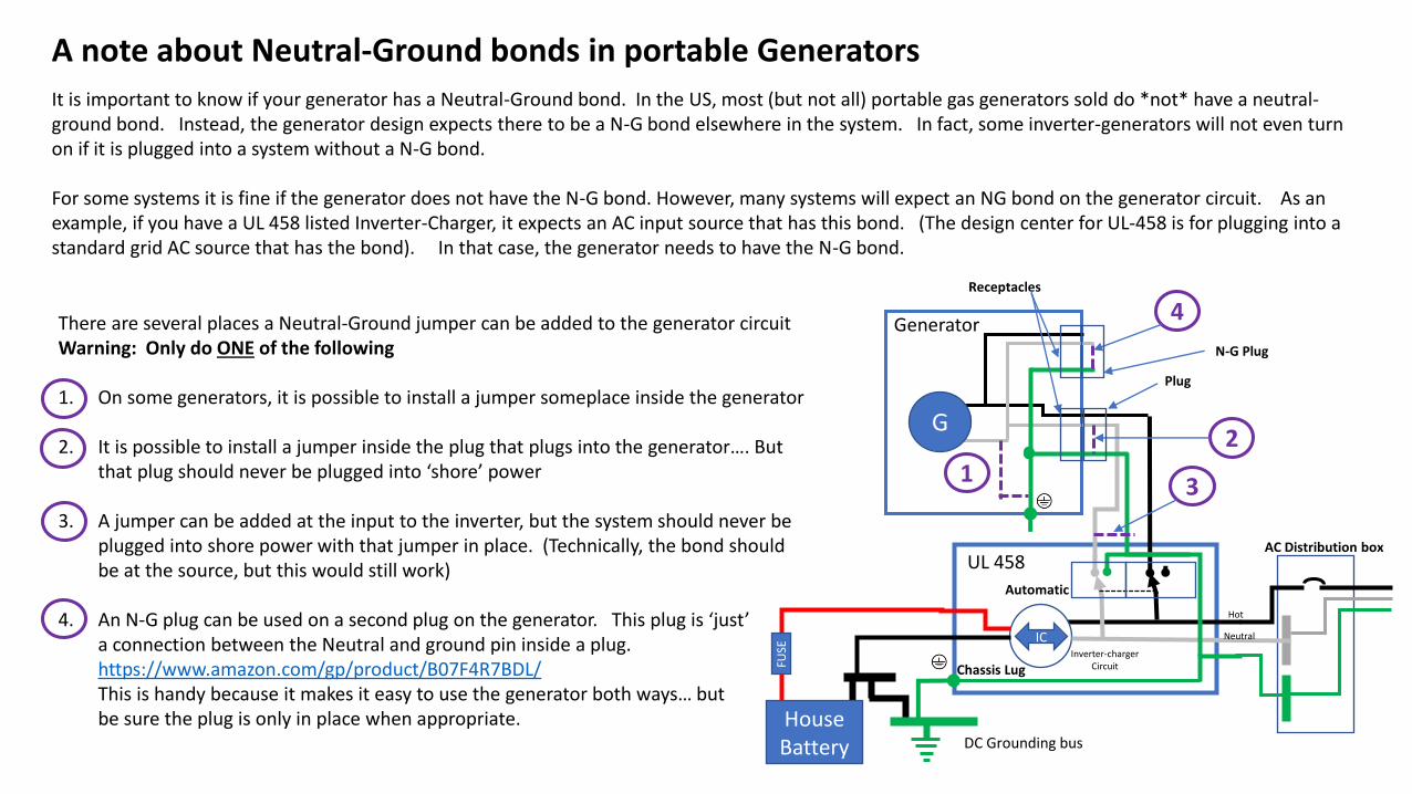
A note about Neutral-Ground bonds in portable Generators
It is important to know if your generator has a Neutral-Ground bond. In the US, most (but not all) portable gas generators sold do *not* have a neutral-ground bond. Instead, the generator design expects there to be a N-G bond elsewhere in the system. In fact, some inverter-generators will not even turn on if it is plugged into a system without a N-G bond.
For some systems it is fine if the generator does not have the N-G bond. However, many systems will expect an NG bond on the generator circuit. As an example, if you have a UL 458 listed Inverter-Charger, it expects an AC input source that has this bond. (The design center for UL-458 is for plugging into a standard grid AC source that has the bond). In that case, the generator needs to have the N-G bond.
DC Grounding bus
ad
AC Distribution box
FUSE
HouseBattery
Hot
Inverter-chargerCircuit
I-C
Chassis Lug
Automatic
UL 458
IC Neutral
G
Generator
Receptacles
Plug
1
2
3
There are several places a Neutral-Ground jumper can be added to the generator circuitWarning: Only do ONE of the following
1. On some generators, it is possible to install a jumper someplace inside the generator
2. It is possible to install a jumper inside the plug that plugs into the generator…. But that plug should never be plugged into ‘shore’ power
3. A jumper can be added at the input to the inverter, but the system should never be plugged into shore power with that jumper in place. (Technically, the bond should be at the source, but this would still work)
4. An N-G plug can be used on a second plug on the generator. This plug is ‘just’a connection between the Neutral and ground pin inside a plug.https://www.amazon.com/gp/product/B07F4R7BDL/This is handy because it makes it easy to use the generator both ways… butbe sure the plug is only in place when appropriate.
4
N-G Plug

SCC
4) Shore Power (with inverter charger.)
Inverter chargers have the transfer switch function built in and therefor must properly manage the tie between neutral and ground.Furthermore, Inverter chargers typically switch from battery to shore power in a seamless manor. Consequently, the internal switching can be quite complex. The diagram below shows a conceptual diagram of how it works.
With this set up, the shore power plug should never be plugged into a generator that does not have a neutral-ground bond. Most portable gas generators sold in the US do not have the bond, but they can be modified to have it.
Note: Some inverter-chargers do not manage the ground-neutral connection as shown below. It is important to find out what the selected invertercharger does and manage the ground-neutral connection appropriately. (If it is a Marine rated or UL 458 listed inverter charger, it switches the Neutral-ground bond appropriately. However, some of them have configuration settings for this so you must read and understand the manual to set it up correctly.)
HouseBattery
DC Fuse Box
DC Grounding bus
DC Loads
FUSE
FUSE SCC
Panels
Chassis
FUSE ad
Sub Panel
No tie from Neutral to grounding system in the ACDistribution box
AC Circuits
AC: When inverter is getting power from shore, it does not tie AC Neutral to groundBAT: When inverter is not using power from shore it ties AC Neutral to ground
AC Grounding Bus
Hot
Inverter-chargerCircuit
I-C
Ground Lug
Automatic
UL 458AC AC Bat
ICNeutral
Shore Power
SCC
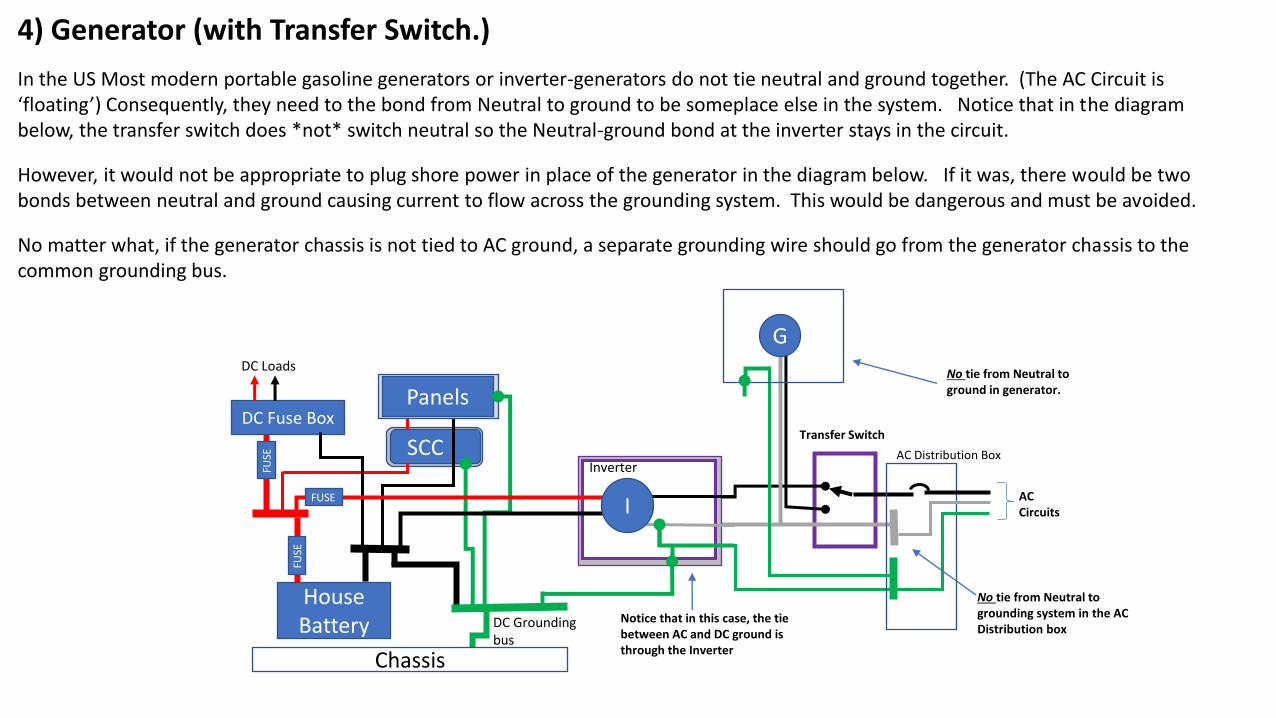
4) Generator (with Transfer Switch.)
In the US Most modern portable gasoline generators or inverter-generators do not tie neutral and ground together. (The AC Circuit is ‘floating’) Consequently, they need to the bond from Neutral to ground to be someplace else in the system. Notice that in the diagram below, the transfer switch does *not* switch neutral so the Neutral-ground bond at the inverter stays in the circuit.
However, it would not be appropriate to plug shore power in place of the generator in the diagram below. If it was, there would be two bonds between neutral and ground causing current to flow across the grounding system. This would be dangerous and must be avoided.
No matter what, if the generator chassis is not tied to AC ground, a separate grounding wire should go from the generator chassis to the common grounding bus.
HouseBattery
DC Fuse Box
DC Grounding bus
DC Loads
FUSE
FUSE SCC
Panels
Chassis
Notice that in this case, the tie between AC and DC ground is through the Inverter
Transfer Switch
ad
AC Distribution Box
No tie from Neutral to grounding system in the ACDistribution box
AC Circuits
or
No tie from Neutral to ground in generator.
Inverter
IFUSE
G

SCC
Inverter-Charger
DC-DC Charger
DC-DC charger from Alternator to House Battery.
Most DC-DC chargers are not ‘isolated’. In other words, the negative input and negative output are tied together. This means that DC negative of the house battery will be tied to chassis via the DC-DC charger. Since the tie between House Battery DC Negative and ground should only be done in one place, the DC-DC charger becomes the bonding point to chassis and the Jumper between the DC negative Bus and the ground bus is removed. Otherwise, a ground loop would be created and possibly create RFI issues.
Some isolated DC-DC chargers are available. These allow more deliberate management for the tie between DC Negative and ground.Isolated chargers are highly recommended for trailer mounted systems. With a non-isolated DC-DC charger, when the trailer is not hitched up, the tie between House DC negative and Chassis ground is lost. When the trailer is hooked up, the path from ground to chassis is long and unreliable.
HouseBattery
DC Fuse Box
Grounding bus
DC Loads
FUSE
FUSE
SCC
Panels
Chassis
FUSE
Shore Power or Generator.
ad
Sub Panel
AC Circuits
Inverter-Charger
A
StarterBattery
DC-DC Charger
FUSE
FUSE
FUSE
Non-isolated
A Non-isolated DC-DC charger becomes the connection between House DC-Negative and Chassis ground
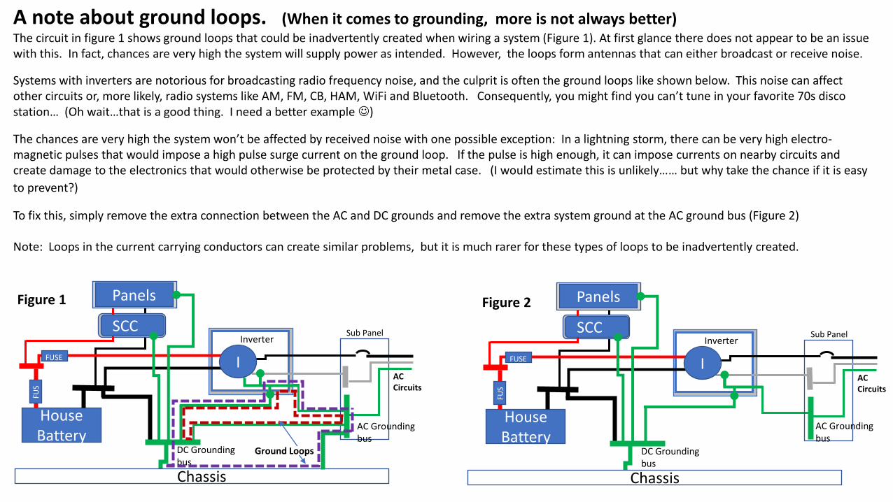
A note about ground loops. (When it comes to grounding, more is not always better)The circuit in figure 1 shows ground loops that could be inadvertently created when wiring a system (Figure 1). At first glance there does not appear to be an issue with this. In fact, chances are very high the system will supply power as intended. However, the loops form antennas that can either broadcast or receive noise.
Systems with inverters are notorious for broadcasting radio frequency noise, and the culprit is often the ground loops like shown below. This noise can affect other circuits or, more likely, radio systems like AM, FM, CB, HAM, WiFi and Bluetooth. Consequently, you might find you can’t tune in your favorite 70s disco station… (Oh wait…that is a good thing. I need a better example ☺)
The chances are very high the system won’t be affected by received noise with one possible exception: In a lightning storm, there can be very high electro-magnetic pulses that would impose a high pulse surge current on the ground loop. If the pulse is high enough, it can impose currents on nearby circuits and create damage to the electronics that would otherwise be protected by their metal case. (I would estimate this is unlikely…… but why take the chance if it is easy
to prevent?)
To fix this, simply remove the extra connection between the AC and DC grounds and remove the extra system ground at the AC ground bus (Figure 2)
Note: Loops in the current carrying conductors can create similar problems, but it is much rarer for these types of loops to be inadvertently created.
SCC
HouseBattery
DC Grounding bus
FUS
E
SCC
Panels
Chassis
ad
Sub Panel
AC Circuits
Inverter
Ground Loops
I
SCC
HouseBattery
DC Grounding bus
FUS
E
SCC
Panels
Chassis
ad
Sub Panel
AC Circuits
Inverter
I
Figure 1 Figure 2
FUSE FUSE
AC Grounding bus
AC Grounding bus
I am *not* a licensed electrician.
I have a degree in electrical engineering. I know a lot about electrical wiring, solar systems and batteries from both personal experience and on-line research. I have studied a lot of the NEC code but do not consider myself an expert on it.
I gladly share my knowledge for free, but you should not consider my advice as 'professional’ advice.
About the author
Corrections
Feedback, Corrections and suggestions are welcome. You can post them in the comment section for the resource at the following link.
https://diysolarforum.com/resources/grounding-made-simpler-part-4-mobile-systems.159/
Updates to this document can be found there as well.