griz lathe g0602
TRANSCRIPT

8/21/2019 Griz Lathe G0602
http://slidepdf.com/reader/full/griz-lathe-g0602 1/96
COPYRIGHT © MARCH, 2013 BY GRIZZLY INDUSTRIAL, INC. REVISED SEPTEMBER, 2014 (ST)
WARNING: NO PORTION OF THIS MANUAL MAY BE REPRODUCED IN ANY SHAPE OR FORM WITHOUT THE WRITTEN APPROVAL OF GRIZZLY INDUSTRIAL, INC.
#BL15556 PRINTED IN CHINA
MODEL G0602/G0752
10" X 22" BENCHTOP LATHE
OWNER'S MANUAL(For models manufactured since 11/12)
G0602 Shown

8/21/2019 Griz Lathe G0602
http://slidepdf.com/reader/full/griz-lathe-g0602 2/96
This manual provides critical safety instructions on the proper setup,
operation, maintenance, and service of this machine/tool. Save this
document, refer to it often, and use it to instruct other operators.
Failure to read, understand and follow the instructions in this manual
may result in fire or serious personal injury—including amputation,
electrocution, or death.
The owner of this machine/tool is solely responsible for its safe use.
This responsibility includes but is not limited to proper installation in
a safe environment, personnel training and usage authorization,
proper inspection and maintenance, manual availability and compre-
hension, application of safety devices, cutting/sanding/grinding toolintegrity, and the usage of personal protective equipment.
The manufacturer will not be held liable for injury or property damage
from negligence, improper training, machine modifications or misuse.
Some dust created by power sanding, sawing, grinding, drilling, and
other construction activities contains chemicals known to the State
of California to cause cancer, birth defects or other reproductive
harm. Some examples of these chemicals are:
• Lead from lead-based paints.
• Crystalline silica from bricks, cement and other masonry products.
• Arsenic and chromium from chemically-treated lumber.
Your risk from these exposures varies, depending on how often you
do this type of work. To reduce your exposure to these chemicals:
Work in a well ventilated area, and work with approved safety equip-
ment, such as those dust masks that are specially designed to filter
out microscopic particles.

8/21/2019 Griz Lathe G0602
http://slidepdf.com/reader/full/griz-lathe-g0602 3/96
Table of ContentsINTRODUCTION ............................................... 3
Machine Description ...................................... 3Contact Info.................................................... 3Manual Accuracy ........................................... 3Model G0602 Identification ............................ 4Model G0752 Identification ............................ 5Controls & Components ................................. 6
Model G0602 Control Panel ...............................6
Model G0752 Control Panel ...............................6
Quick Change Gearbox ......................................6
Carriage ..............................................................7
Tailstock ..............................................................7
Change Gears, Pulleys, V-Belt ...........................7
Machine Data Sheet ...................................... 8
SECTION 1: SAFETY ..................................... 10Safety Instructions for Machinery ................ 10Additional Safety for Metal Lathes ............... 12
Glossary of Terms ....................................... 13
SECTION 2: POWER SUPPLY ...................... 14Availability .........................................................14
Full-Load Current Rating ..................................14
Circuit Requirements ........................................14
Grounding & Plug Requirements ......................15
Extension Cords................................................ 15
SECTION 3: SETUP ....................................... 16Unpacking .................................................... 16Needed for Setup ......................................... 16
Inventory ...................................................... 17Cleanup ........................................................ 18Site Considerations ...................................... 19Lifting & Placing ........................................... 20Leveling & Mounting .................................... 21
Leveling .............................................................21
Mounting ........................................................... 21
Assembly ..................................................... 22Lubricating Lathe ......................................... 22Power Connection........................................ 22
Connecting Power .............................................22
Disconnecting Power ........................................22
Test Run ...................................................... 22Spindle Break-In .......................................... 24Recommended Adjustments ........................ 24
SECTION 4: OPERATIONS ........................... 25Operation Overview ..................................... 25Chuck & Faceplate Mounting....................... 26Installation & Removal Devices ................... 26Chuck Installation......................................... 27Chuck Removal............................................ 28Changing Jaw Set ........................................ 28Scroll Chuck Clamping ................................ 294-Jaw Chuck ................................................ 30Faceplate ..................................................... 31Tailstock ....................................................... 32
Positioning Tailstock .........................................32
Using Quill .........................................................32
Installing Tooling ...............................................32
Removing Tooling .............................................33
Offsetting Tailstock ...........................................33
Aligning Tailstock to Spindle Centerline ...........34
Centers ........................................................ 36Dead Centers ....................................................36
Live Centers ......................................................36
Mounting Dead Center in Spindle .....................36
Removing Center from Spindle ......................... 37
Mounting Center in Tailstock ............................37
Removing Center from Tailstock ......................37
Mounting Workpiece Between Centers ............ 38
Steady Rest ................................................. 38Follow Rest .................................................. 39Carriage & Slide Locks ................................ 39Compound Rest ........................................... 39
Four-Way Tool Post ..................................... 40Installing Tool ....................................................40
Aligning Cutting Tool with Spindle Centerline ...40
Manual Feed ................................................ 41Spindle Speed.............................................. 42
Determining Spindle Speed ..............................42
Setting Spindle Speed ......................................42
G0602 Configuration Examples ........................ 42
G0752 Configuration Example ..........................43
Power Feed.................................................. 44Setting Power Feed Rate ..................................45
Threading ..................................................... 46
Headstock Threading Controls .........................46
Apron Threading Controls .................................47
Thread Dial Chart .............................................47

8/21/2019 Griz Lathe G0602
http://slidepdf.com/reader/full/griz-lathe-g0602 4/96
SECTION 5: ACCESSORIES ......................... 49
SECTION 6: MAINTENANCE ......................... 51Schedule ...................................................... 51
Ongoing ............................................................51
Daily, Before Operations ................................... 51
Daily, After Operations ......................................51
Annually ............................................................51
Cleaning/Protecting ...................................... 51Lubrication ................................................... 52
Quick-Change Gearbox .................................... 52
Ball Oilers .......................................................... 53
Leadscrew & Carriage Rack ............................. 54
Bedways ........................................................... 54
Compound Slide ............................................... 54
Change Gears ...................................................55
Machine Storage .......................................... 56
SECTION 7: SERVICE ................................... 57Troubleshooting ........................................... 57
Operation .......................................................... 58Backlash Adjustment ................................... 60Compound Rest ................................................60
Cross Slide ........................................................60
Gib Adjustment ............................................ 61Half Nut Adjustment ..................................... 62Leadscrew Shear Pin Replacement ............ 62V-Belt Tension & Replacement.................... 63
Tensioning V-Belt..............................................63
Replacing V-Belt ...............................................64
Timing Belt Tension & Replacement ........... 65Tensioning Timing Belt .....................................65
Replacing Timing Belt .......................................65
SECTION 8: WIRING ...................................... 66Wiring Safety Instructions ............................ 66G0602 Wiring Diagram ................................ 67G0602 Electrical Components ..................... 68G0752 Wiring Box Diagram ......................... 69G0752 Wiring Box Components .................. 70G0752 Control Panel Wiring Diagram ......... 71G0752 Control Panel Components .............. 72
G0752 Motor Wiring Diagram ...................... 73
SECTION 9: PARTS ....................................... 74Spindle & Drive Belt ..................................... 74Apron ........................................................... 76Tool Post & Compound Rest ....................... 77Tailstock ....................................................... 78Bed & Leadscrew ......................................... 79Steady Rest & Follow Rest .......................... 80G0602 Motor & Electrical ............................. 81G0752 Motor & Electrical ............................. 82Change Gears.............................................. 83
Gearbox ....................................................... 84Cross Slide & Carriage ................................ 86
SECTION 10: APPENDIX ............................... 89G0602 Charts............................................... 89G0752 Charts............................................... 90
WARRANTY AND RETURNS ........................ 93

8/21/2019 Griz Lathe G0602
http://slidepdf.com/reader/full/griz-lathe-g0602 5/96Model G0602/G0752 (Mfg. Since 11/12) -3-
INTRODUCTION
The metal lathe is used to remove material froma rotating workpiece, which is held in place onthe spindle with a chuck or faceplate. The cuttingtool is mounted on the carriage or tailstock andmoved against the spinning workpiece to performthe cut.
Typical metal lathe cutting operations include fac-ing, turning, parting, drilling, reaming, grooving,knurling, and threading. There are a wide varietyof tools and workpiece holding devices available
for each of these operations.
Models G0602 and G0752 both require settinggearbox dial positions and positioning V-belts toselect the spindle speed. However, the ModelG0752 features an electronic variable-speed con-trol and digital RPM display that make it possibleto select speeds within the selected range whilethe machine is running.
Machine Description
We are proud to provide a high-quality owner’smanual with your new machine!
We made every effort to be exact with the instruc-tions, specifications, drawings, and photographscontained inside. Sometimes we make mistakes,but our policy of continuous improvement alsomeans that sometimes the machine you receivewill be slightly different than what is shown inthe manual.
If you find this to be the case, and the differencebetween the manual and machine leaves youconfused about a procedure, check our websitefor an updated version. We post current manualsand manual updates for free on our website atwww.grizzly.com.
Alternatively, you can call our Technical Supportfor help. Before calling, please write down theManufacture Date and Serial Number stampedinto the machine ID label (see below). This infor-mation helps us determine if updated documenta-
tion is available for your machine.
Manufacture Date
Serial Number
Manual Accuracy
We stand behind our machines. If you haveany questions or need help, use the informationbelow to contact us. Before contacting, please getthe serial number and manufacture date of yourmachine. This will help us help you faster.
Grizzly Technical Support1203 Lycoming Mall Circle
Muncy, PA 17756
Phone: (570) 546-9663Email: [email protected]
We want your feedback on this manual. What didyou like about it? Where could it be improved?Please take a few minutes to give us feedback.
Grizzly Documentation ManagerP.O. Box 2069
Bellingham, WA 98227-2069Email: [email protected]
Contact Info

8/21/2019 Griz Lathe G0602
http://slidepdf.com/reader/full/griz-lathe-g0602 6/96-4- Model G0602/G0752 (Mfg. Since 11/12)
L. Chip TrayM. Thread DialN. Half Nut Lever
O. Cross Slide HandwheelP. Carriage HandwheelQ. LeadscrewR. Alpha Gearbox DialS. Gearbox Oil Level Sight GlassT. Numeric Gearbox DialU. Change Gear and Belt Safety Cover
A. Emergency Stop ButtonB. Spindle Direction SwitchC. ON Button
D. 3-Jaw ChuckE. Steady RestF. 4-Way Tool PostG. Follow RestH. Compound Rest HandwheelI. MT#3 Dead CenterJ. TailstockK. Back Splash
Model G0602 Identification
U
TS R
QP
ON
M
L
K
J
IH
GF
EDC
B
A
Figure 1. G0602 identification.
Serious personal injury could occur ifyou connect the machine to power beforecompleting the setup process. DO NOTconnect power until instructed to do solater in this manual.
Untrained users have an increased riskof seriously injuring themselves with thismachine. Do not operate this machine untilyou have understood this entire manualand received proper training.

8/21/2019 Griz Lathe G0602
http://slidepdf.com/reader/full/griz-lathe-g0602 7/96Model G0602/G0752 (Mfg. Since 11/12) -5-
M. TailstockN. Back SplashO. Chip TrayP. Thread DialQ. Half Nut Lever R. Cross Slide HandwheelS. Carriage HandwheelT. LeadscrewU. Alpha Gearbox DialV. Gearbox Oil Level Sight Glass
W. Numeric Gearbox DialX. Change Gear and Belt Safety Cover
A. Emergency Stop ButtonB. ON ButtonC. OFF ButtonD. Spindle Speed RPM DisplayE. Spindle Speed DialF. Spindle Direction SwitchG. 3-Jaw ChuckH. Steady RestI. 4-Way Tool PostJ. Follow Rest
K. Compound Rest HandwheelL. MT#3 Dead Center
RQ
M
LI
H
C
B
A
Model G0752 Identification
D
G
FE
K
Figure 2. G0752 identification.
Serious personal injury could occur ifyou connect the machine to power beforecompleting the setup process. DO NOTconnect power until instructed to do solater in this manual.
Untrained users have an increased riskof seriously injuring themselves with thismachine. Do not operate this machine untilyou have understood this entire manualand received proper training.
J N
OS
T
P
UV
W
X

8/21/2019 Griz Lathe G0602
http://slidepdf.com/reader/full/griz-lathe-g0602 8/96-6- Model G0602/G0752 (Mfg. Since 11/12)
Controls &Components
Refer to Figures 3–8 and the following descrip-tions to become familiar with the basic controls of
this lathe.
D. OFF Button: Stops spindle rotation.
E. Spindle Speed RPM Display: Shows a digi-tal readout of the spindle speed.
F. Spindle Speed Dial: Controls the variablespindle speed.
Model G0752 Control Panel
Figure 4. Model G0752 control panel.
FE
B
A
C D
Model G0602 Control Panel
Figure 3. Model G0602 control panel.
A. Emergency STOP Button: Cuts power tothe motor and control panel when pressed.Remains depressed until reset by twistingclockwise.
B. Spindle Switch: Starts, stops, and reversesspindle rotation.
C. ON Button: Enables spindle rotation.
A B C
G. Numeric Gearbox Dial: Controls theleadscrew for threading and feeding opera-tions. To make a selection, rotate the dial tothe corresponding number displayed on thethreading or feed charts.
H. Alpha Gearbox Dial: Controls the leadscrewfor threading and feeding operations. Tomake a selection, rotate the dial to the cor-responding letter displayed on the threadingor feed charts.
Quick Change Gearbox
Figure 5. Gearbox dials.
G H

8/21/2019 Griz Lathe G0602
http://slidepdf.com/reader/full/griz-lathe-g0602 9/96Model G0602/G0752 (Mfg. Since 11/12) -7-
Carriage Tailstock
I. 4-Way Tool Post: Holds up to four cuttingtools at once that can be individually indexed
to the workpiece.
J. Compound Rest Handwheel: Moves thetool toward and away from the workpiece atthe preset angle of the compound rest.
K. Carriage Lock: Secures the carriage forgreater rigidity when it should not move.
L. Thread Dial: Indicates when to engage thehalf nut during threading operations.
M. Half Nut Lever: Engages/disengages halfnut for power feed and threading operations.
N. Thread Chart: Indicates which thread dialmark to use when engaging the half nut forspecific inch thread pitches.
O. Cross Slide Handwheel: Moves the crossslide toward and away from the workpiece.
P. Carriage Handwheel: Moves the carriagealong the bedway.
Q. Tailstock Quill: Moves a tool or centermounted in the tailstock toward or away fromthe workpiece.
R. Tailstock Quill Lock Lever: Secures thequill position.
S. Tailstock Lock Nut: Secures the tailstock tothe bedway.
Figure 6. Carriage controls.
I
L
J
MOP
K
NT. Tailstock Quill Handwheel: Controls the
movement of the quill.
U. Offset Scale: Indicates the relative distanceof tailstock offset from the spindle centerline.
V. Tailstock Offset Set Screw (1 of 2): Adjuststhe tailstock offset left or right from the spin-dle centerline.
Change Gears, Pulleys, V-BeltW. Change Gears: The configuration of the
change gears for power feed, inch, and met-ric threading controls the leadscrew speed.
X. Pulleys: The position of the V-belt on the pul-leys controls the spindle speed.
Y. V-Belt: Transfers power from the motor pul-ley to the spindle pulley. Model G0602 usestwo V-belts. Model G0752 uses one V-belt.
Z. Timing-Belt: (G0602) Transfers power fromthe motor to the secondary drive pulley.
Figure 7. Tailstock controls.
Q
S T
UV
R
Figure 8. Change gears and pulleys(Model G0602 shown).
X
W
Y
Z

8/21/2019 Griz Lathe G0602
http://slidepdf.com/reader/full/griz-lathe-g0602 10/96-8- Model G0602/G0752 (Mfg. Since 11/12)
MODEL G0602, G075210" x 22" Bench Top Metal Lathe
Model Number G0602 G0752
Product Dimensions
Weight 330 lbs.
Width/Depth/Height 46" x 22" x 165 ⁄ 8" 501 ⁄ 2" x 22" x 165 ⁄ 8"
Foot Print (Width/Depth) 471 ⁄ 2" x 121 ⁄ 2"
Shipping Dimensions
Type Wood Crate
Content Machine
Weight 432 lbs. 453 lbs.
Width /Depth/Height 55" x 23" x 22"
Electrical
Power Requirement 110V, Single-Phase, 60 Hz
Minimum Circuit Size 20A 15A
Switch Forward & Reverse Button Switches
Cord Length 5 ft.
Cord Gauge 16 AWG 16 AWG
Plug Included Yes
Included Plug Type NEMA 5-15
Main Motor
Type TEFC Capacitor-Start Induction TEFC Induction
Horsepower 1 HP 1 HP
Phase Single-Phase 3-Phase
Amps 13.6A 12A
Speed 1725 RPM
Power Transfer Cogged Belt Drive
Bearings Shielded & Permanently Sealed
Operation InformationSwing Over Bed 95 ⁄ 8"
Distance Between Centers 22 in.
Swing Over Cross Slide 61 ⁄ 8 in.
Swing Over Saddle 61 ⁄ 8 in.
Maximum Tool Bit Size 1 ⁄ 2 in.
Compound Travel 31 ⁄ 2
Carriage Travel 181 ⁄ 2 in.
Cross Slide Travel 61 ⁄ 2 in.

8/21/2019 Griz Lathe G0602
http://slidepdf.com/reader/full/griz-lathe-g0602 11/96Model G0602/G0752 (Mfg. Since 11/12) -9-
Model Number G0602 G0752
Headstock Information
Spindle Bore 1"
Spindle Size 13 ⁄ 4"
Spindle Taper MT#4
Spindle Threads 8 TPI
Number of Spindle Speeds 6 VariableRange of Spindle Speeds 150 – 2400 RPM 100 – 800, 160 – 1300, 250 – 2000 RPM
Spindle Type Threaded
Spindle Bearings Tapered Roller
Tailstock Information
Tailstock Quill Travel 21 ⁄ 2"
Tailstock Taper MT#3
Tailstock Barrel Diameter 1.25"
Threading Information
Number of Longitudinal Feeds 9
Range of Longitudinal Feeds 0.0025 – 0.0140 in./rev.Number of Inch Threads 33
Range of Inch Threads 8 – 72 TPI
Number of Metric Threads 26
Range of Metric Threads 0.25 – 3.50 mm
Dimensions
Bed Width 61 ⁄ 8 in.
Leadscrew Diameter 3 ⁄ 4 in.
Leadscrew TPI 12 TPI
Leadscrew Length 34"
Steady Rest Capacity1
⁄ 4"– 2"Follow Rest Capacity 1 ⁄ 4"– 2"
Faceplate Size 8 in.
Construction
Base Cast Iron
Headstock Cast Iron
Headstock Gears Steel
Bed Hardened and Precision-Ground Cast Iron
Stand Cast Iron
Paint Epoxy
Other Country of Origin China
Warranty 1 Year
Serial Number Location ID Label on Headstock
Approximate Assembly & Setup
Time1 Hour

8/21/2019 Griz Lathe G0602
http://slidepdf.com/reader/full/griz-lathe-g0602 12/96-10- Model G0602/G0752 (Mfg. Since 11/12)
ELECTRICAL EQUIPMENT INJURY RISKS. Youcan be shocked, burned, or killed by touching liveelectrical components or improperly groundedmachinery. To reduce this risk, only allow qualifiedservice personnel to do electrical installation orrepair work, and always disconnect power beforeaccessing or exposing electrical equipment.
DISCONNECT POWER FIRST. Always discon-nect machine from power supply BEFORE makingadjustments, changing tooling, or servicing machine.This prevents an injury risk from unintended startupor contact with live electrical components.
EYE PROTECTION. Always wear ANSI-approvedsafety glasses or a face shield when operating orobserving machinery to reduce the risk of eyeinjury or blindness from flying particles. Everydayeyeglasses are NOT approved safety glasses.
OWNER’S MANUAL. Read and understand thisowner’s manual BEFORE using machine.
TRAINED OPERATORS ONLY. Untrained oper-ators have a higher risk of being hurt or killed.Only allow trained/supervised people to use thismachine. When machine is not being used, dis-connect power, remove switch keys, or lock-outmachine to prevent unauthorized use—especiallyaround children. Make workshop kid proof!
DANGEROUS ENVIRONMENTS. Do not usemachinery in areas that are wet, cluttered, or havepoor lighting. Operating machinery in these areasgreatly increases the risk of accidents and injury.
MENTAL ALERTNESS REQUIRED. Full mentalalertness is required for safe operation of machin-ery. Never operate under the influence of drugs oralcohol, when tired, or when distracted.
For Your Own Safety, Read Instruction
Manual Before Operating This MachineThe purpose of safety symbols is to attract your attention to possible hazardous conditions.This manual uses a series of symbols and signal words intended to convey the level of impor-tance of the safety messages. The progression of symbols is described below. Remember thatsafety messages by themselves do not eliminate danger and are not a substitute for properaccident prevention measures. Always use common sense and good judgment.
Indicates a potentially hazardous situation which, if not avoided,
MAY result in minor or moderate injury. It may also be used to alertagainst unsafe practices.
Indicates a potentially hazardous situation which, if not avoided,
COULD result in death or serious injury.
Indicates an imminently hazardous situation which, if not avoided,
WILL result in death or serious injury.
This symbol is used to alert the user to useful information aboutproper operation of the machine.NOTICE
Safety Instructions for Machinery
SECTION 1: SAFETY

8/21/2019 Griz Lathe G0602
http://slidepdf.com/reader/full/griz-lathe-g0602 13/96Model G0602/G0752 (Mfg. Since 11/12) -11-
WEARING PROPER APPAREL. Do not wearclothing, apparel or jewelry that can becomeentangled in moving parts. Always tie back orcover long hair. Wear non-slip footwear to avoidaccidental slips, which could cause loss of work-piece control.
HAZARDOUS DUST. Dust created while usingmachinery may cause cancer, birth defects, orlong-term respiratory damage. Be aware of dusthazards associated with each workpiece material,and always wear a NIOSH-approved respirator toreduce your risk.
HEARING PROTECTION. Always wear hear-ing protection when operating or observing loudmachinery. Extended exposure to this noise
without hearing protection can cause permanenthearing loss.
REMOVE ADJUSTING TOOLS. Tools left onmachinery can become dangerous projectilesupon startup. Never leave chuck keys, wrenches,or any other tools on machine. Always verifyremoval before starting!
USE CORRECT TOOL FOR THE JOB. Only usethis tool for its intended purpose—do not forceit or an attachment to do a job for which it was
not designed. Never make unapproved modifica-tions—modifying tool or using it differently thanintended may result in malfunction or mechanicalfailure that can lead to personal injury or death!
AWKWARD POSITIONS. Keep proper footingand balance at all times when operating machine.Do not overreach! Avoid awkward hand positionsthat make workpiece control difficult or increasethe risk of accidental injury.
CHILDREN & BYSTANDERS. Keep children and
bystanders at a safe distance from the work area.Stop using machine if they become a distraction.
GUARDS & COVERS. Guards and covers reduceaccidental contact with moving parts or flyingdebris. Make sure they are properly installed,undamaged, and working correctly.
FORCING MACHINERY. Do not force machine.It will do the job safer and better at the rate forwhich it was designed.
NEVER STAND ON MACHINE. Serious injurymay occur if machine is tipped or if the cuttingtool is unintentionally contacted.
STABLE MACHINE. Unexpected movement dur-ing operation greatly increases risk of injury orloss of control. Before starting, verify machine isstable and mobile base (if used) is locked.
USE RECOMMENDED ACCESSORIES. Consultthis owner’s manual or the manufacturer for rec-ommended accessories. Using improper acces-sories will increase the risk of serious injury.
UNATTENDED OPERATION. To reduce therisk of accidental injury, turn machine OFF andensure all moving parts completely stop beforewalking away. Never leave machine runningwhile unattended.
MAINTAIN WITH CARE. Follow all maintenanceinstructions and lubrication schedules to keepmachine in good working condition. A machinethat is improperly maintained could malfunction,leading to serious personal injury or death.
CHECK DAMAGED PARTS. Regularly inspectmachine for any condition that may affect safeoperation. Immediately repair or replace damagedor mis-adjusted parts before operating machine.
MAINTAIN POWER CORDS. When disconnect-ing cord-connected machines from power, graband pull the plug—NOT the cord. Pulling the cordmay damage the wires inside. Do not handlecord/plug with wet hands. Avoid cord damage bykeeping it away from heated surfaces, high traffic
areas, harsh chemicals, and wet/damp locations.
EXPERIENCING DIFFICULTIES. If at any timeyou experience difficulties performing the intend-ed operation, stop using the machine! Contact ourTechnical Support at (570) 546-9663.

8/21/2019 Griz Lathe G0602
http://slidepdf.com/reader/full/griz-lathe-g0602 14/96-12- Model G0602/G0752 (Mfg. Since 11/12)
Additional Safety for Metal Lathes
SPEED RATES. Operating the lathe at the wrongspeed can cause nearby parts to break or theworkpiece to come loose, which will result in dan-
gerous projectiles that could cause severe impactinjuries. Large or non-concentric workpieces mustbe turned at slow speeds. Always use the appro-priate feed and speed rates.
CHUCK KEY SAFETY. A chuck key left in thechuck can become a deadly projectile when thespindle is started. Always remove the chuck keyafter using it. Develop a habit of not taking yourhand off of a chuck key unless it is away from themachine.
SAFE CLEARANCES. Workpieces that crashinto other components on the lathe may throwdangerous projectiles in all directions, leading toimpact injury and damaged equipment. Beforestarting the spindle, make sure the workpiece hasadequate clearance by hand-rotating it through itsentire range of motion. Also, check the tool andtool post clearance, chuck clearance, and saddleclearance.
LONG STOCK SAFETY. Long stock can whip
violently if not properly supported, causing seriousimpact injury and damage to the lathe. Reduce thisrisk by supporting any stock that extends from thechuck/headstock more than three times its owndiameter. Always turn long stock at slow speeds.
CRASHES. Aggressively driving the cutting tool orother lathe components into the chuck may causean explosion of metal fragments, which can resultin severe impact injuries and major damage tothe lathe. Reduce this risk by releasing automaticfeeds after use, not leaving lathe unattended, and
checking clearances before starting the lathe.Make sure no part of the tool, tool holder, com-pound rest, cross slide, or carriage will contact thechuck during operation.
SECURING WORKPIECE. An improperly securedworkpiece can fly off the lathe spindle with deadlyforce, which can result in a severe impact injury.
Make sure the workpiece is properly secured in thechuck or faceplate before starting the lathe.
CHUCKS. Chucks are very heavy and difficult tograsp, which can lead to crushed fingers or handsif mishandled. Get assistance when handlingchucks to reduce this risk. Protect your hands andthe precision-ground ways by using a chuck cradleor piece of plywood over the ways of the lathewhen servicing chucks. Use lifting devices whennecessary.
CLEARING CHIPS. Metal chips can easily cutbare skin—even through a piece of cloth. Avoidclearing chips by hand or with a rag. Use a brushor vacuum to clear metal chips.
STOPPING SPINDLE BY HAND. Stopping thespindle by putting your hand on the workpieceor chuck creates an extreme risk of entangle-ment, impact, crushing, friction, or cutting hazards.Never attempt to slow or stop the lathe spindle withyour hand. Allow the spindle to come to a stop on
its own or use the brake.
TOOL SELECTION. Cutting with an incorrect ordull tool increases the risk of accidental injury dueto the extra force required for the operation, whichincreases the risk of breaking or dislodging com-ponents that can cause small shards of metal tobecome dangerous projectiles. Always select theright cutter for the job and make sure it is sharp. Acorrect, sharp tool decreases strain and providesa better finish.

8/21/2019 Griz Lathe G0602
http://slidepdf.com/reader/full/griz-lathe-g0602 15/96Model G0602/G0752 (Mfg. Since 11/12) -13-
The following is a list of common definitions, terms and phrases used throughout this manual as they relateto this lathe and metalworking in general. Become familiar with these terms for assembling, adjusting oroperating this machine. Your safety is VERY important to us at Grizzly!
Arbor: A machine shaft that supports a cuttingtool.
Backlash: Wear in a screw or gear mechanismthat may result in slippage, vibration, and lossof tolerance.
Carriage: A main housing that consists of theapron and the saddle.
Cross Slide: A fixture attached to the lathe car-
riage that holds the compound rest and can bemoved in and out.
Compound Rest: A fixture attached to the crossslide that holds the tool holder and can bemoved in and out.
Cutting Speed: The distance a point on a cuttermoves in one minute, expressed in meters orfeet per minute.
Dial Indicator: An instrument used in setup
and inspection work that shows on a dial theamount of error in size or alignment of a part.
Facing: In lathe work, cutting across the end ofa workpiece, usually to machine a flat surface.
Feed: The movement of a cutting tool into aworkpiece.
Fixture: A device that securely holds theworkpiece in place during cutting operationas opposed to a jig which is used to hold and
guide a workpiece through an operation.
Gib: A tapered wedge located along a slidingmember to take up wear or to ensure a properfit.
Headstock: The major lathe component thathouses the spindle and motor drive system toturn the workpiece.
Lathe Center: A lathe accessory with a 60°point which is inserted into the headstock ortailstock of the lathe and is used to support theworkpiece.
Leadscrew: Lathe—The long screw that is driv-en by the change gears and supplies power tothe carriage.
Saddle: The upper portion of carriage that rideson the lathe ways and supports the cross feed
and the follow rest.
Spindle: The revolving shaft that holds anddrives the workpiece or cutting tool.
Tailstock: A moveable fixture opposite of theheadstock on a lathe that has a spindle usedto support one end of a workpiece and for hold-ing tools.
Tool Post: The part of the compound rest thatholds the tool holder.
Turret: Lathe—A machine fixture that holds mul-tiple tools and can be revolved and indexed toposition.
Ways: The precision machined and flat trackson a lathe on which the carriage and tailstockslide.
Glossary of Terms

8/21/2019 Griz Lathe G0602
http://slidepdf.com/reader/full/griz-lathe-g0602 16/96-14- Model G0602/G0752 (Mfg. Since 11/12)
SECTION 2: POWER SUPPLY
AvailabilityBefore installing the machine, consider the avail-ability and proximity of the required power supply
circuit. If an existing circuit does not meet therequirements for this machine, a new circuit mustbe installed. To minimize the risk of electrocution,fire, or equipment damage, installation work andelectrical wiring must be done by an electrican orqualified service personnel in accordance with allapplicable codes and standards.
Electrocution, fire, or
equipment damage mayoccur if machine is notcorrectly grounded andconnected to the powersupply.
Full-Load Current RatingThe full-load current rating is the amperage amachine draws at 100% of the rated output power.On machines with multiple motors, this is theamperage drawn by the largest motor or sum of allmotors and electrical devices that might operateat one time during normal operations.
G0602 Full-Load Rating ...........................13.6A
G0752 Full-Load Rating ..............................12A
The full-load current is not the maximum amountof amps that the machine will draw. If the machineis overloaded, it will draw additional amps beyondthe full-load rating.
If the machine is overloaded for a sufficient lengthof time, damage, overheating, or fire may result—especially if connected to an undersized circuit.To reduce the risk of these hazards, avoid over-loading the machine during operation and makesure it is connected to a power supply circuit thatmeets the requirements in the following section.
For your own safety and protection ofproperty, consult an electrician if you areunsure about wiring practices or electricalcodes in your area.
Note: The circuit requirements listed in this man- ual apply to a dedicated circuit—where only onemachine will be running at a time. If this machinewill be connected to a shared circuit where mul- tiple machines will be running at the same time,consult a qualified electrician to ensure that thecircuit is properly sized for safe operation.
A power supply circuit includes all electricalequipment between the main breaker box or fusepanel in your building and the incoming powerconnections inside the machine. This circuit must
be safely sized to handle the full-load current thatmay be drawn from the machine for an extendedperiod of time.
Circuit RequirementsThis machine is prewired to operate on a 110Vpower supply circuit that has a verified ground and
meets the following requirements:
Nominal Voltage ...............................110V/120VCycle ..........................................................60 HzPhase ........................................... Single-PhaseMinimum Circuit Size (G0602) .......... 20 AmpsMinimum Circuit Size (G0752) .......... 15 Amps

8/21/2019 Griz Lathe G0602
http://slidepdf.com/reader/full/griz-lathe-g0602 17/96Model G0602/G0752 (Mfg. Since 11/12) -15-
Improper connection of the equipment-grounding
wire can result in a risk of electric shock. Thewire with green insulation (with or without yellowstripes) is the equipment-grounding wire. If repair
or replacement of the power cord or plug is nec-essary, do not connect the equipment-groundingwire to a live (current carrying) terminal.
Check with a qualified electrician or service per-sonnel if you do not understand these groundingrequirements, or if you are in doubt about whetherthe tool is properly grounded. If you ever notice
that a cord or plug is damaged or worn, discon-nect it from power, and immediately replace it witha new one.
Extension CordsWe do not recommend using an extension cordwith this machine. If you must use an extension
cord, only use it if absolutely necessary and onlyon a temporary basis.
Extension cords cause voltage drop, which maydamage electrical components and shorten motorlife. Voltage drop increases as the extension cord
size gets longer and the gauge size gets smaller(higher gauge numbers indicate smaller sizes).
Any extension cord used with this machine mustcontain a ground wire, match the required plug
and receptacle, and meet the following require-ments:
Minimum Gauge Size ...........................14 AWGMaximum Length (Shorter is Better).......50 ft.
Figure 9. Included 5-15 plug and receptacle.
Grounding Prong
Neutral Hot
5-15 PLUG
GROUNDED
5-15 RECEPTACLE
Serious injury could occur if you connectthe machine to power before completing thesetup process. DO NOT connect to power
until instructed later in this manual.
SHOCK HAZARD!Two-prong outlets do not meet the groundingrequirements for this machine. Do not modifyor use an adapter on the plug provided—ifit will not fit the outlet, have a qualifiedelectrician install the proper outlet with averified ground.
Grounding & Plug RequirementsThis machine MUST be grounded. In the eventof certain malfunctions or breakdowns, grounding
reduces the risk of electric shock by providing apath of least resistance for electric current.
This machine is equipped with a power cord that
has an equipment-grounding wire and a ground-ing plug (similar to the figure below). The plugmust only be inserted into a matching receptacle(outlet) that is properly installed and grounded in
accordance with all local codes and ordinances.

8/21/2019 Griz Lathe G0602
http://slidepdf.com/reader/full/griz-lathe-g0602 18/96-16- Model G0602/G0752 (Mfg. Since 11/12)
SECTION 3: SETUP
Your machine was carefully packaged for safetransportation. Remove the packaging materialsfrom around your machine and inspect it. If youdiscover any damage, please call us immediatelyat (570) 546-9663 for advice.
Save the containers and all packing materials forpossible inspection by the carrier or its agent.Otherwise, filing a freight claim can be difficult.
When you are completely satisfied with the condi-
tion of your shipment, inventory the contents.
Unpacking
SUFFOCATION HAZARD!Keep children and pets awayfrom plastic bags or packingmaterials shipped with thismachine. Discard immediately.
The following are needed to complete the setupprocess, but are not included with your machine.
Description Qty• Additional People ....................................... 1• Safety Glasses ............... 1 For Each Person• Cleaner/Degreaser (Page 18) .... As Needed• Quality Metal Protectant ............. As Needed• Disposable Shop Rags ............... As Needed• Precision Level ........................................... 1• Lifting Straps (rated for at least 500 lbs.) ... 2
• Forklift/Power Lifting Device (rated for at least500 lbs.) ...................................................... 1
• Bench Mounting Hardware ........ As Needed
Needed for Setup

8/21/2019 Griz Lathe G0602
http://slidepdf.com/reader/full/griz-lathe-g0602 19/96Model G0602/G0752 (Mfg. Since 11/12) -17-
Inventory
The following is a list of items shipped with yourmachine. Before beginning setup, lay these itemsout and inventory them.
If any non-proprietary parts are missing (e.g. anut or a washer), we will gladly replace them; orfor the sake of expediency, replacements can beobtained at your local hardware store.
Installed Components (Figure 10) Qty.A. 5" Three-Jaw Chuck ................................... 1B. Steady Rest ................................................ 1C. Follow Rest ................................................. 1D. 4-Way Tool Post ......................................... 1E. Compound Rest ......................................... 1F. Tailstock ...................................................... 1
Figure 11. Packaged components.
I
J
K
L
M N
OP Q
R
S
U V
W
H
T
NOTICE If you cannot find an item on this list, care-fully check around/inside the machine andpackaging materials. Often, these items get
lost in packaging materials while unpack-ing or they are pre-installed at the factory.
Figure 10. Installed components.
D EA B C F
Packaged Components (Figure 11) Qty.G. Chip Pan (Not Shown) ................................ 1H. Hex Wrench Set (2.5, 3, 4, 5, 6 mm) .....1 EaI. Tool Box...................................................... 1J. 8" Faceplate ............................................... 1K. 61 ⁄ 2" 4-Jaw Universal Chuck ....................... 1L. Low Range Belt 271 ⁄ 2" (G0602) .................. 1 High Range Belt 33" (Installed, G0602) ..... 1 V-Belt 33" (Installed, G0752) ...................... 1M. #2 Phillips and Standard Screwdriver ...1 EaN. Wrench Set (8/10, 12/14, 19/17mm) .......1 EaO. 3-Jaw Chuck Internal Jaw Set .................... 1P. 3-Jaw Chuck Key ....................................... 1Q 4-Jaw Chuck Key ....................................... 1R. Oil Bottle for Oil .......................................... 1S. Cross Slide Handwheel Handle ................. 1T. Carriage Handwheel Handle ...................... 1U. Dead Centers MT#3 .................................. 2
V. Dead Center MT#4 ..................................... 1W. Change Gear Set ....................................... 1 — Change Gear (27-tooth, Installed) ......... 1 — Change Gear (36-tooth) ......................... 1 — Change Gear (40-tooth) ......................... 1 — Change Gear (44-tooth) ......................... 1 — Change Gear (45-tooth) ......................... 1 — Change Gear (46-tooth) ......................... 1
— Change Gear (48-tooth) ......................... 1 — Change Gear (52-tooth) ......................... 1 — Change Gear (56-tooth, Installed) ......... 1 — Change Gear (60-tooth) ......................... 1 — Plastic Drive Gear (60-tooth, Installed) .. 1 — Change Gear (104-tooth, Installed) ....... 1 — Change Gear (120-tooth) ....................... 1 — Change Gear (127-tooth, Installed) ........ 1X. Frequency Drive Manual VFD-E (G0752, Not
Shown) ....................................................... 1

8/21/2019 Griz Lathe G0602
http://slidepdf.com/reader/full/griz-lathe-g0602 20/96-18- Model G0602/G0752 (Mfg. Since 11/12)
The unpainted surfaces of your machine arecoated with a heavy-duty rust preventative thatprevents corrosion during shipment and storage.This rust preventative works extremely well, but it
will take a little time to clean.
Be patient and do a thorough job cleaning yourmachine. The time you spend doing this now willgive you a better appreciation for the proper careof your machine's unpainted surfaces.
There are many ways to remove this rust preven-tative, but the following steps work well in a widevariety of situations. Always follow the manufac-turer’s instructions with any cleaning product youuse and make sure you work in a well-ventilated
area to minimize exposure to toxic fumes.
Before cleaning, gather the following:• Disposable Rags• Cleaner/degreaser (WD•40 works well)• Safety glasses & disposable gloves• Plastic paint scraper (optional)
Basic steps for removing rust preventative:
1. Put on safety glasses.
2. Coat the rust preventative with a liberalamount of cleaner/degreaser, then let it soakfor 5–10 minutes.
3. Wipe off the surfaces. If your cleaner/degreas-er is effective, the rust preventative will wipeoff easily. If you have a plastic paint scraper,scrape off as much as you can first, then wipeoff the rest with the rag.
4. Repeat Steps 2–3 as necessary until clean,
then coat all unpainted surfaces with a qualitymetal protectant to prevent rust.
Gasoline or productswith low flash points canexplode or cause fire ifused to clean machin-ery. Avoid cleaning with
these products.
Many cleaning solventsare toxic if concentrat-ed amounts are inhaled.Only work in a well-venti-lated area.
NOTICE Avoid chlorine-based solvents, such asacetone or brake parts cleaner, that maydamage painted surfaces. Test all cleanersin an inconspicuous area before using tomake sure they will not damage paint.
Cleanup
T23692—Orange Power DegreaserA great product for removing the waxy shippinggrease from your machine during clean up.
Figure 12. T23692 Orange Power Degreaser.

8/21/2019 Griz Lathe G0602
http://slidepdf.com/reader/full/griz-lathe-g0602 21/96Model G0602/G0752 (Mfg. Since 11/12) -19-
12.5" 30"
47.5"
65"
KeepWorkpieceLoading AreaUnobstructed
Access Door Lathe
110VSupply
Footprint
Footprint
18"
Wall
Min. 30"
for Maintenance
Figure 13. Minimum working clearances.
Site Considerations
Weight LoadRefer to the Machine Data Sheet for the weightof your machine. Make sure that the surface upon
which the machine is placed will bear the weightof the machine, additional equipment that may beinstalled on the machine, and the heaviest work-piece that will be used. Additionally, consider theweight of the operator and any dynamic loadingthat may occur when operating the machine.
Space AllocationConsider the largest size of workpiece that willbe processed through this machine and provideenough space around the machine for adequateoperator material handling or the installation ofauxiliary equipment. With permanent installations,leave enough space around the machine to openor remove doors/covers as required by the main-tenance and service described in this manual.See below for required space allocation.
Physical EnvironmentThe physical environment where the machine isoperated is important for safe operation and lon-
gevity of machine components. For best results,operate this machine in a dry environment that isfree from excessive moisture, hazardous chemi-cals, airborne abrasives, or extreme conditions.Extreme conditions for this type of machinery aregenerally those where the ambient temperaturerange exceeds 41°–104°F; the relative humidityrange exceeds 20–95% (non-condensing); or theenvironment is subject to vibration, shocks, orbumps.
Electrical InstallationPlace this machine near an existing power source.Make sure all power cords are protected fromtraffic, material handling, moisture, chemicals,or other hazards. Make sure to leave access toa means of disconnecting the power source orengaging a lockout/tagout device, if required.
LightingLighting around the machine must be adequateenough that operations can be performed safely.Shadows, glare, or strobe effects that may distractor impede the operator must be eliminated.
Children or untrained peoplemay be seriously injured bythis machine. Only install in an
access restricted location.

8/21/2019 Griz Lathe G0602
http://slidepdf.com/reader/full/griz-lathe-g0602 22/96-20- Model G0602/G0752 (Mfg. Since 11/12)
Lifting & Placing
HEAVY LIFT!Straining or crushing injurymay occur from improperlylifting machine or some ofits parts. To reduce this risk,get help from other peopleand use a forklift (or otherlifting equipment) rated forweight of this machine.
Do not attempt to lift or move this lathe withoutusing the proper lifting equipment (such as forkliftor crane) or the necessary assistance from other
people. Refer to Needed for Setup on Page 16for details.
To lift and move the lathe:
1. Remove the shipping crate top and sides,then remove the chip pan, 4-jaw chuck, face-plate, and toolbox from the shipping pallet.
2. Position the chip pan on the selected mount-ing surface and use it as a template to markthe hole locations for the mounting hardware(refer to Leveling & Mounting on Page 21).
3. Unbolt the lathe from the shipping pallet.
5. Wrap the lifting straps around the bed andbetween the leadscrew and the bedway, asshown in Figure 14, to help prevent bendingthe leadscrew during lifting.
6. Attach the lifting straps to the power liftingequipment, have an assistant steady theload, then lift it just enough to clear anyobstacles and move it to its mounting posi-tion.
7. Properly mount the lathe as instructed in theMounting subsection on Page 21.
Figure 14. Example of lifting strap positions.
4. To balance the load for lifting, move thetailstock and carriage to the extreme rightend of the bedway, then lock them in place.
Note: Before attempting to move the car- riage, make sure the carriage lock is looseand the half nut is disengaged.
Only use lifting straps and power liftingequipment rated for at least 500 lbs. and ingood working condition. If the lathe falls ortips over while moving it, serious personalinjury and property damage could result.

8/21/2019 Griz Lathe G0602
http://slidepdf.com/reader/full/griz-lathe-g0602 23/96Model G0602/G0752 (Mfg. Since 11/12) -21-
The chip pan and the base of the lathe haveholes that allow the machine to be mounted toa workbench. You MUST mount your machineto a workbench to prevent it from unexpectedlymoving during operation, which could lead topersonal injury or property damage.
Follow these guidelines when mounting yourlathe to ensure safe and accurate cuttingresults:
• Make sure that the workbench can adequate-ly support the weight of the machine andmaterials and that it will not move or vibrateduring operation.
• Use a silicon sealant between the lathe andthe chip pan to prevent coolant or other fluids
from leaking through onto the bench or floor.
To mount the lathe and chip pan to the workbench,drill holes all the way through the workbench, anduse hex bolts, washers, and hex nuts to securethe lathe to the workbench, as illustrated inFigure 16.
Leveling & Mounting
Figure 15. Grizzly Model H2683 12" MasterMachinist's Level.
Leveling machinery helps precision components,such as bedways, remain straight and flat duringthe lifespan of the machine. Components on a
machine that is not level may slowly twist due tothe dynamic loads placed on the machine duringoperation.
For best results, use a precision level that is atleast 12" long and sensitive enough to show adistinct movement when a 0.003" shim (approxi-mately the thickness of one sheet of standardnewspaper) is placed under one end of the level.
See the figure below for an example of a highprecision level.
Leveling
Mounting
Chip Pan
Workbench
Hex Bolt
Flat Washer
Flat Washer
Silicon
Lock Washer
Hex Nut
Lathe
Figure 16. Example of a through mount setup.
For accurate turning results and to preventwarping the cast iron bed and ways, the lathe
bedways MUST be leveled from side-to-sideand from front-to-back on both ends.
Re-check the bedways 24 hours afterinstallation, two weeks after that, and thenannually to make sure they remain level.

8/21/2019 Griz Lathe G0602
http://slidepdf.com/reader/full/griz-lathe-g0602 24/96-22- Model G0602/G0752 (Mfg. Since 11/12)
Power Connection
Lubricating Lathe
The lathe must be properly lubricated before it canbe operated for the first time.
Damage caused to the bearings and gears fromrunning the lathe without oil in the reservoirswill not be covered under warranty. Refer to theLubrication section, beginning on Page 52, fordetails on how to lubricate the lathe.
GEARBOX MUST
BE FILLED WITH OIL!
LATHE MAY NOT
HAVE OIL INCLUDED!
Refer to the LubricationSection in this Manual
for RecommendedOil Type.
Assembly
With the exception of the handwheel handles, thelathe is shipped fully assembled.
To install the handwheel handles, thread the large
handle into the carriage handwheel and the smallhandle into the cross slide handwheel, as shownin Figure 17.
Figure 17. Handwheel handles installed.
Before the machine can be connected to thepower source, an electrical circuit and connec-tion device must be prepared per the POWERSUPPLY section in this manual, and all previ-
ous setup instructions in this manual must becompleted to ensure that the machine has beenassembled and installed properly.
Connecting PowerAlways make sure the spindle direction switch onthe front of the headstock is turned OFF (middleposition) before connecting power.
Insert the power cord plug into a matching powersupply receptacle.
Disconnecting PowerIf you need to disconnect the machine from powerfor maintenance, service, or adjustments, turn themachine off and pull the plug completely out ofthe receptacle.
Once the assembly is complete, test run yourmachine to make sure it runs properly and isready for regular operation.
The test run consist of verifying the following: 1)The motor powers up and runs correctly, 2) theemergency STOP button safety feature workscorrectly.
If, during the test run, you cannot easily locatethe source of an unusual noise or vibration, stopusing the machine immediately, then review
Troubleshooting on Page 57.
If you still cannot remedy a problem, contact ourTech Support at (570) 546-9663 for assistance.
Test Run
LargeHandle
SmallHandle

8/21/2019 Griz Lathe G0602
http://slidepdf.com/reader/full/griz-lathe-g0602 25/96Model G0602/G0752 (Mfg. Since 11/12) -23-
7. Reset the emergency STOP button by twist-ing it clockwise until it pops out.
To test run your machine:
1. Make sure the spindle direction switch (seeFigure 18) is turned to STOP, and press theemergency STOP button.
5. Set lathe spindle speed for 150 RPM, (referto Setting Spindle Speed on Page 42).
6. Disengage the half nut with the lever shownin Figure 19.
Figure 18. Headstock and gearbox controls.
3. Clear away all tools and objects used duringassembly, lubrication, and preparation.
4. Make sure chuck and jaws, if installed, aresecure (see Chuck Installation on Page 27).
Note: If a chuck is not installed on the lathe,you do not need to install one for this test.
2. Read and follow the safety instructions at thebeginning of the manual, take all requiredsafety precautions, and make sure all pre-vious preparation steps discussed in thismanual have been followed and completed.
EmergencyStop Button
Spindle Direction SwitchPointing to STOP
8. G0752 Only: Ensure the spindle speed dial isturned all the way counterclockwise.
Push the green ON button, then turn thespindle direction switch to FWD. Turn thespindle speed dial until the spindle speeddisplay shows 150 RPM. The spindle shouldbe rotating counterclockwise—down andtoward you as you face the lathe.
G0602: Push the green ON button, then turn
the spindle direction switch to FWD. Thespindle should be rotating counterclockwise—down and toward you as you face the lathe.
9. Push the emergency STOP button to turn thelathe OFF, then, without resetting the STOPbutton, try to restart spindle rotation. Thespindle should not start.
—If spindle rotation does start with theemergency STOP button pressed in, thebutton is not operating correctly. This
safety feature must operate properlybefore continuing operation. Use thespindle direction switch to stop the lathe,disconnect it from power, and call TechSupport for help.
Congratulations! The test run is complete. Turnthe lathe OFF and perform the following SpindleBreak-In procedure.
ONButton
Figure 19. Half nut lever in the disengagedposition.
Engaged
Halfnut
Lever
Disengaged
Half NutLever

8/21/2019 Griz Lathe G0602
http://slidepdf.com/reader/full/griz-lathe-g0602 26/96-24- Model G0602/G0752 (Mfg. Since 11/12)
Before subjecting the lathe to full loads, it is essen-tial to complete the spindle break-in process. Thiswill ensure the best results and maximum life ofthe precision components inside the lathe.
The break-in procedure must be performed insuccession with the Test Run procedure becausemany of the test run steps prepare the lathe con-trols for the break-in process.
Important: Do not perform the break-in procedureindependently from the Test Run section—seri- ous damage could occur to the lathe if the controlsare set differently than instructed in that section.
Spindle Break-In
To perform the spindle break-in:
1. Operate the lathe at 150 RPM for 10 minutes.
2. G0602: Repeat Step 1 at each of the followingspeeds 300, 560, 720, 1200, and 2400.
G0752: Repeat Step 1 at each of the followingapproximate speeds: 800, 1300, and 2000.
3. When the spindle has come to a completestop, run the spindle in reverse at 2400 RPM
(Model G0602) or 2000 RPM (Model G0752)for another 10 minutes, then press theemergency STOP button and DISCONNECTTHE LATHE FROM POWER!
4. Check, and if necessary, re-tension the drivebelts (refer to V-Belt Tension & Replacement Page 64 on page for detailed instructions.)
5. While the oil is still warm and any metal par-ticles are still suspended in the oil, changethe gearbox oil (refer to Lubrication on Page
52 for detailed instructions).
Congratulations! The spindle break-in is com-plete. Continue with the following RecommendedAdjustments subsection.
RecommendedAdjustments
For your convenience, the adjustments listedbelow have been performed at the factory.However, because of the many variables involvedwith shipping, we recommend that you at leastverify the following adjustments to ensure the bestpossible results from your new machine. Step-by-step instructions for these adjustments can befound on the pages referenced below.
Factory adjustments that should be verified:
• Tailstock alignment (Page 33)• Gib adjustments (Page 61)• Backlash adjustment (Page 60)

8/21/2019 Griz Lathe G0602
http://slidepdf.com/reader/full/griz-lathe-g0602 27/96Model G0602/G0752 (Mfg. Since 11/12) -25-
Complete the Test Run & Break-In proce-dure on Pages 22– 24 before using this lathefor any cutting or threading operations; oth-erwise, gear box damage will occur.
SECTION 4: OPERATIONS
Operation Overview
The purpose of this overview is to provide the nov-ice machine operator with a basic understandingof how the machine is used during operation, sothe machine controls/components discussed laterin this manual are easier to understand.
Due to the generic nature of this overview, it isnot intended to be an instructional guide. To learnmore about specific operations, read this entiremanual and seek additional training from expe-rienced machine operators, and do additionalresearch outside of this manual by reading "how-
to" books, trade magazines, or websites.
To reduce your risk ofserious injury, read thisentire manual BEFOREusing machine.
If you are not experienced with this typeof machine, WE STRONGLY RECOMMENDthat you seek additional training outside ofthis manual. Read books/magazines or get
formal training before beginning any proj-ects. Regardless of the content in this sec-tion, Grizzly Industrial will not be held liablefor accidents caused by lack of training.
To reduce risk of eye injuryfrom flying chips alwayswear safety glasses or faceshield when operating.
To complete a typical operation, the operatordoes the following:
1. Puts on safety glasses, rolls up sleeves,
removes jewelry, and secures any clothing, jewelry, or hair that could get entangled inmoving parts.
2. Examines the workpiece to make sure it issuitable for turning, then securely mounts theworkpiece in a chuck, between centers, or onthe faceplate.
3. Mounts the tooling, aligns it with the workpiece,then backs it away to establish a safe startupclearance.
4. Clears all setup tools from the lathe.
5. Checks for safe clearances by rotating theworkpiece by hand at least one full revolution.
6. Sets the correct spindle speed for the opera-tion.
7. If using power feed, selects the proper feedrate for the operation.
8. Starts spindle rotation, then engages the halfnut.
9. Uses various carriage controls to move thetooling into the workpiece for operations.
10. When finished cutting, disengages the halfnut (power feed only), moves the spindledirection switch to the OFF position, waits forthe spindle to completely stop, then removesthe workpiece.

8/21/2019 Griz Lathe G0602
http://slidepdf.com/reader/full/griz-lathe-g0602 28/96-26- Model G0602/G0752 (Mfg. Since 11/12)
This lathe ships with the 3-jaw chuck installed.
This is a scroll-type chuck where all three jawsmove in unison when the chuck key is used.
The included 4-jaw chuck features independent jaws, which are used for square or unevenly-shaped stock, and to mount work that needs to beadjusted to near zero total indicated runout.
If neither chuck can hold your workpiece, thecast iron faceplate has slots for T-bolts that holdstandard or custom clamping hardware. With thecorrect clamping hardware, a faceplate offers a
wide range of uses, including machining non-concentric workpieces, straight turning betweencenters, off-center turning, and boring.
This lathe is equipped with a threaded spindlenose. With this type of spindle, a chuck or face-
plate is screwed directly onto the spindle nose.
Never use spindle speeds faster than thechuck RPM rating or the safe limits ofyour workpiece. Excessive spindle speedsgreatly increase the risk of the workpiece orchuck being thrown from the machine withdeadly force!
Chuck & FaceplateMounting
Installation &Removal Devices
Figure 20. Examples of common devices usedduring chuck installation and removal.
A dropped chuck can cause amputation,serious crushing injuries, or property dam-age. Always use a support or protectivedevice to reduce this risk when installing orremoving a chuck.
Loose hair, clothing, orjewelry could get caughtin machinery and causeserious personal injury.Keep these items awayfrom moving parts at alltimes to reduce this risk.
Because chucks are heavy and often awkward tohold, some kind of support or protective device
should be used during installation or removal. Theweight and size of the chuck will determine theappropriate device to use (refer to the followingfigure for examples).

8/21/2019 Griz Lathe G0602
http://slidepdf.com/reader/full/griz-lathe-g0602 29/96Model G0602/G0752 (Mfg. Since 11/12) -27-
Chuck Installation 5. Insert the chuck wrenches as shown inFigure 22, and tighten the chuck until it isseated snug against the spindle shoulder.
Figure 22. Location to insert chuck keys wheninstalling chuck.
To ensure accurate work, it is extremely importantto make sure the spindle nose and chuck matingsurfaces are clean. Even a small amount of lint ordebris can affect accuracy.
The chuck is properly installed when it threadsall the way onto the spindle nose (see Figure 21 below) and is seated against the spindle shoulder.
6. Install the chuck locks with the cap screws(see Figure 23).
Figure 23. Chuck lock installed on spindle noseand chuck.
Chuck Lock
Cap Screw
4. Thread the chuck onto the spindle nose andhand-tighten it.
3. Thoroughly clean, inspect, deburr, and lightly
oil all threads and mating surfaces.
To install the chuck:
1. DISCONNECT LATHE FROM POWER!
2. Use an appropriate device to protect the waysand support the chuck during the installationprocess (refer to Installation & RemovalDevices on Page 26).
Tools Needed: QtyChuck Wrenches ............................................... 2
Hex Wrench 5mm .............................................. 1
Figure 21. Spindle nose.
Threads
InsideTaper
SpindleShoulder

8/21/2019 Griz Lathe G0602
http://slidepdf.com/reader/full/griz-lathe-g0602 30/96-28- Model G0602/G0752 (Mfg. Since 11/12)
Figure 25. Location to insert chuck keys whenremoving chuck.
Figure 24. Location of chuck lock and capscrews.
Chuck Lock
Cap Screw
4. Insert the chuck wrenches, as shown inFigure 25, then while holding the spindle,unthread the chuck in a counterclockwisedirection.
5. Support the chuck, unscrew it, and remove.
To remove the chuck:
1. DISCONNECT LATHE FROM POWER!
2. Use an appropriate device to protect the waysand support the chuck (refer to Installation &Removal Devices on Page 26).
3. Remove the cap screws and chuck locks(see Figure 24).
Chuck Removal Changing Jaw Set
The 3-jaw scroll chuck included with the lathe fea-
tures inside and outside hardened steel jaw sets(see Figure 26), which move in unison to centera concentric workpiece.
When installing the jaws, it is important to makesure they are installed correctly. Incorrect installa-tion will result in jaws that do not converge evenlyand are unable to securely clamp a workpiece.
Jaws are numbered from 1–3 (see Figure 27).They are designed to be installed in numericalorder in the jaw guides so they will hold a concen-tric workpiece evenly.
Figure 26. Chuck and jaw selection.
InsideSet
Insert KeysHere
Tools Needed: QtyChuck Wrenches ............................................... 2Hex Wrench 5mm .............................................. 1
Tools Needed: QtyChuck Wrench ................................................... 1
Figure 27. Jaw guide and jaw numbers.
Jaw Numbers
OutsideSet
JawGuides

8/21/2019 Griz Lathe G0602
http://slidepdf.com/reader/full/griz-lathe-g0602 31/96Model G0602/G0752 (Mfg. Since 11/12) -29-
4. Use mineral spirits to clean the debris andgrime from the jaws and chuck jaw guides.
5. Apply a thin coat of white lithium grease tothe surfaces of the removed jaw set. Storein a safe place free from moisture and abra-sives.
6. Rotate the chuck key clockwise until you seethe tip of the scroll-gear lead thread just beginto enter a jaw guide (see Figure 28).
9. Install the remaining jaws in numerical order,
in the same manner.
—If installed correctly, the jaws will convergeevenly at the center of the chuck.
—If the jaws do not converge evenly, removethem. Re-install the jaws sequentially 1–3,and make sure each one engages with thescroll-gear lead thread during its first rota-tion.
To change the jaw set:
1. DISCONNECT LATHE FROM POWER!
2. Place a piece of plywood over the bedways toprotect them from potential damage.
3. Insert the chuck key and turn it counterclock-
wise to back the jaws out and remove them.
Figure 28. Lead thread on scroll gear.
Lead Thread
7. Insert jaw #1 into the jaw guide and hold the jaw against the scroll-gear.
8. Rotate the chuck key clockwise one turn toengage the tip of the scroll-gear lead threadinto the jaw. Pull the jaw; it should be lockedinto the jaw guide.
The 3-jaw scroll-type chuck has an internalscroll-gear that moves all jaws in unison when
adjusted with the chuck key. The chuck will holdcylindrical parts on-center with the axis of spindlerotation and can be rotated at high speeds if theworkpiece is properly clamped and balanced.
Never mix jaw types or positions toaccommodate an odd-shaped workpiece. Thechuck will spin out of balance and may throwthe workpiece! Instead, use an independent jawchuck or a faceplate.
InsufficientJaw Clamping
UnstableWorkpiece
Bar Stock
Cylinder
Unsafe Jaw Position
Poor ScrollGear Engagement
Safer InsideJaw Use
Unsafe InsideJaw Use
Unsafe JawPosition
Safer OutsideJaw Use
Poor Scroll Gear EngagementUnsafe Jaw Position and
Poor Scroll
GearEngagement
Poor Grip
UnstableWorkpiece
ShallowBar Stock
ShallowBar Stock
Safer Outside
Jaw Use
Safer InsideJaw Use
CORRECT
CORRECT
CORRECT
CORRECT
INCORRECT
INCORRECT
INCORRECT
INCORRECT
Scroll ChuckClamping
Figure 29. Jaw selection and workpiece holding.

8/21/2019 Griz Lathe G0602
http://slidepdf.com/reader/full/griz-lathe-g0602 32/96-30- Model G0602/G0752 (Mfg. Since 11/12)
Refer to the Chuck Installation (see Page 27)and Chuck Removal (see Page 28) instructionsto install or remove the 4-jaw chuck.
The 4-jaw chuck features independently adjust-able hardened steel jaws for holding non-con-centric or off-center workpieces. Each jaw canbe independently removed from the chuck bodyand reversed for a wide range of work holdingversatility.
To mount the workpiece:
1. DISCONNECT LATHE FROM POWER!
2. Place a chuck cradle or plywood on thebedway below the chuck to protect thebedway surfaces.
3. Use the chuck key to open each jaw so theworkpiece will lay flat against the chuck face,
jaw steps, or into the spindle opening.
4. With help from another person or a holdingdevice, position the workpiece so it is cen-
tered in the chuck.
Because of the dynamic forces involved inmachining a non-concentric or off-center
workpiece, always use a low spindle speedto reduce risk of the workpiece coming looseand being thrown from the lathe, which couldcause death or serious personal injury.
4-Jaw Chuck
Figure 30. 4-jaw tightening sequence.
1
2
3
4
Workpiece
Center Point
5. Tighten each jaw in small increments. Afteryou have adjusted the first jaw, continuetightening the remaining jaws in an opposingsequence, as shown by the sequential orderin Figure 30.
6. After the workpiece is held in place by the jaws, use a dial indicator to make sure theworkpiece is centered in the chuck.
—If the workpiece is not correctly centered,make fine adjustments by slightly loosen-ing one jaw and tightening the opposing
jaw until the workpiece is correctly posi-tioned (see Figure 31 for an example).
Figure 31. Generic picture of non-cylindricalworkpiece correctly mounted on the 4-jaw chuck.
Tools Needed: Qty4-Jaw Chuck Key .............................................. 1Dial Indicator ..................................................... 1

8/21/2019 Griz Lathe G0602
http://slidepdf.com/reader/full/griz-lathe-g0602 33/96Model G0602/G0752 (Mfg. Since 11/12) -31-
Faceplate
Refer to the Chuck Installation (see Page 27)and Chuck Removal (see Page 28) instructionsto install or remove the faceplate.
The faceplate included with your lathe can beused for a wide range of operations, includingmachining non-concentric workpieces, straightturning between centers, off-center turning, andboring.
The tools needed for mounting a workpiece willvary depending on the type of setup you have.
Machining non-concentric workpieces at ahigh speed could cause the workpiece to bethrown from the spindle with deadly forceat the operator or bystanders. To reducethis risk, only machine non-concentricworkpieces at low speeds and clampcounter-weights to the faceplate to balanceit.
Failure to properly secure a workpiece tothe faceplate could cause the workpiece tobe thrown from the lathe with deadly force atthe operator or bystanders. Use a minimumof THREE independent clamping devices tohold the workpiece onto the faceplate.
To mount a non-concentric workpiece to thefaceplate:
1. DISCONNECT LATHE FROM POWER!
2. Protect the bedway with a piece of plywood.
3. With help from another person or a holding
device to support the workpiece, position itonto the faceplate and clamp it in place witha minimum of three independent clampingdevices (see Figure 32 for an example).
Be sure to take into account the rotationaland cutting forces that will be applied to theworkpiece when clamping it to the faceplate.If necessary, use counter-weights to balancethe assembly and use a dial indicator to makesure that the workpiece is properly positionedfor your operation.
Figure 32. Generic picture of workpiece clampedin a faceplate.
Faceplate
Non-CylindricalWorkpiece
Clamp

8/21/2019 Griz Lathe G0602
http://slidepdf.com/reader/full/griz-lathe-g0602 34/96-32- Model G0602/G0752 (Mfg. Since 11/12)
The tailstock (see Figure 33) is typically used tosupport long workpieces by means of a live ordead center (refer to Centers on Page 36). It canalso be used to hold a drill or chuck to bore holes
in the center of a part. Custom arbors and taperscan also be cut on your lathe by using the offsettailstock adjustment.
Tailstock
Figure 33. Tailstock and quill lock handles inlocked position.
TailstockLock Nut
Quill LockLever
Quill Handwheel
Graduated DialIncrements ................................................. 0.001"One Full Revolution ...................................0.060"
Increments on QuillInch ..............................0"-21 ⁄ 2" in 1 ⁄ 8" IncrementsMetric ..................... 0–65mm in 1mm Increments
Positioning Tailstock 1. Loosen the tailstock lock nut to unlock the
tailstock from the bedway.
2. Slide the tailstock to the desired position.
3. Tighten the tailstock lock nut to lock the
tailstock against the bedway.
Using Quill1. Loosen the quill lock lever.
2. Turn the quill handwheel clockwise to movethe quill toward the spindle or counterclock-wise to move it away from it.
3. Tighten the quill lock lever.
Installing ToolingThis tailstock uses a quill with an MT#3 taper thataccepts a variety of tapered arbors and tooling,including tang arbors and drill bits (see Figures34–35 for examples).
Figure 34. Types of tapered arbors and tooling.
SolidEnd
OpenEnd
SolidEnd
Screw
End
Tang
Figure 35. Example photos of inserting MT#3tools with tangs into a typical tailstock.
Tang
Note: If the tooling has an open hole in the end,then a screw can be threaded into the end of thetool to provide a solid surface for the quill pin topush against when the quill is retracted for toolremoval. Otherwise, removal of such tooling maybe difficult.

8/21/2019 Griz Lathe G0602
http://slidepdf.com/reader/full/griz-lathe-g0602 35/96Model G0602/G0752 (Mfg. Since 11/12) -33-
To install tooling in the tailstock:
1. With the tailstock locked in place, unlock thequill, then use the handwheel to extend itapproximately 1".
2. Thoroughly clean and dry the tapered matingsurfaces of the quill and the center, making
sure that no lint or oil remains on the tapers.
Removing Tooling1. Use a shop rag to hold the tool.
2. Rotate the quill handwheel counterclockwiseuntil the tool is forced out of the quill.
Offsetting Tailstock The tailstock can be offset from the spindle cen-terline for turning tapers. Move the tailstock topcasting toward the front of the lathe to machine ataper at the tailstock end. Conversely, position thetailstock top casting toward the back of the latheto machine a taper at the spindle end.
Note: The marks on the offset indicator are arbi- trary. For a precise offset, use a dial indicator tocheck quill movement while adjusting the screws.
Tools Needed QtyHex Wrench 4mm .............................................. 1Open-End Wrench 19mm .................................. 1
3. With a firm and quick motion, insert the toolinto the quill, as shown in Figure 35 on Page32. Check to see if it is firmly seated byattempting to twist it—a firmly seated tool willnot twist.
4. Unlock the tailstock and move it until the tipof the tool is close to, but not touching, theworkpiece, then re-lock the tailstock.
5. Start spindle rotation, unlock the quill locklever, then turn the quill handwheel clockwiseto feed the tool into the workpiece.
To offset the tailstock:
1. Loosen the tailstock lock nut (see Figure 36).
2. Rotate the adjustment set screws in oppositedirections for the desired offset (see the illus-tration in Figure 37).
Turn
CCW
Turn
CCW
Turn
CW
Turn
CW
Figure 37. Set screw adjustment in relation totailstock movement.
3. Retighten the tailstock lock nut to secure theoffset.
Figure 36. Left offset adjustment.
TailstockLock Nut
AdjustmentSet Screw(1 of 2)
OffsetIndicator

8/21/2019 Griz Lathe G0602
http://slidepdf.com/reader/full/griz-lathe-g0602 36/96-34- Model G0602/G0752 (Mfg. Since 11/12)
This is an essential adjustment that should be ver-ified or performed each time the tailstock is usedto turn concentric workpieces between centersor immediately after offsetting the tailstock whenturning a taper. If the tailstock is not aligned with
the spindle centerline when it is supposed to be,turning results will be inaccurate along the lengthof the workpiece.
Items Needed QtyHex Wrench 4mm .............................................. 1Open-End Wrench 19mm .................................. 1Round Stock 2" x 6" .......................................... 2Precision Level .................................................. 1Precision Calipers ............................................. 1Dial Indicator ..................................................... 1
To align the tailstock to the spindle center-line:
1. Use the precision level to make sure thebedway is level from side-to-side and fromfront-to-back.
—If the bedway is not level, correct this con-dition before continuing (refer to Leveling& Mounting on Page 21).
2. Center drill both ends of one piece of roundstock, then set it aside for use in Step 5.
3. Use the other piece of round stock to makea dead center, and turn it to a 60° point, asillustrated in Figure 38.
Figure 38. Turning a dead center.
Aligning Tailstock to SpindleCenterline
Note: As long as this dead center remains inthe chuck, the point of the center will remaintrue to the spindle centerline. The point willhave to be refinished whenever the center isremoved and then returned to the chuck.
4. Install a center in the tailstock.
5. Attach a lathe dog to the test stock from Step2, then mount it between the centers (seeFigure 39 for an example).
Figure 39. Example photo of stock mountedbetween the centers.
6. Turn 0.010" off the stock diameter.
7. Mount a test or dial indicator so that theplunger is on the tailstock quill.
Note: If necessary in the following step,refer to Offsetting Tailstock on Page 33 fordetailed instructions.

8/21/2019 Griz Lathe G0602
http://slidepdf.com/reader/full/griz-lathe-g0602 37/96Model G0602/G0752 (Mfg. Since 11/12) -35-
8. Use calipers to measure both ends of theworkpiece.
—If the test stock is thicker at the tailstockend, move the tailstock toward the front ofthe lathe 1 ⁄ 2 the distance of the amount oftaper (see Figure 40).
9. Repeat Steps 6–8 until the desired accuracyis achieved.
Move the tailstock toward
the front of the machine half
the distance of the taper
Looking down from above
Figure 40. Adjust tailstock toward the operator.
—If the test stock is thinner at the tailstockend, move the tailstock toward the back ofthe lathe 1 ⁄ 2 the distance of the amount oftaper (see Figure 41).
Move tailstock toward the
back of the machine half
the distance of the taper
Looking down from above
Figure 41. Adjust tailstock away from theoperator.

8/21/2019 Griz Lathe G0602
http://slidepdf.com/reader/full/griz-lathe-g0602 38/96-36- Model G0602/G0752 (Mfg. Since 11/12)
Figure 42 shows one of the two included MT#3dead centers and the MT#4 dead center.
Centers
Figure 42. Dead centers.
MT#3 DeadCenter
MT#4 DeadCenter
Dead Centers
A dead center is a one-piece center that does not
rotate with the workpiece and is used to support
long, slender workpieces in the tailstock.
A carbide-tipped dead center (not included) canbetter withstand the effects of friction than a typi-cal dead center and is best used in the tailstockwhere the workpiece will rotate against it. The tipof a dead center must be generously lubricatedduring the operation to avoid premature wear and
maximize smooth operation. Using low spindlespeeds will also reduce the heat and wear fromfriction.
Use the dead center in the spindle for operationswhere the workpiece rotates with the center anddoes not generate friction.
The spindle taper is an MT#4 and will only receivethe MT#4 dead center. The tailstock quill taperis an MT#3 and will only receive the MT#3 deadcenters.
Live CentersA live center (not included) has bearings thatallow the center tip and the workpiece to rotatetogether; it can be installed in the tailstock quill forhigher speeds.
Mounting Dead Center in Spindle1. DISCONNECT LATHE FROM POWER!
2. Thoroughly clean and dry all threads andmating surfaces of the spindle bore and thecenter, making sure that no lint or oil remainson these surfaces.
Note: This will prevent the tapered surfacesfrom seizing due to operational pressures,which could make it very difficult to removethe center.
3. Mount a chuck or faceplate onto the spindle,whichever is correct for your operation.
4. Insert the center into the spindle bore throughthe chuck or faceplate.
Figure 43 shows an example photo of a deadcenter installed in the spindle, using a lathedog and faceplate for turning between cen-ters.
Figure 43. Example photo of using a deadcenter with a faceplate and lathe dog.
Dead Center
Lathe
Dog

8/21/2019 Griz Lathe G0602
http://slidepdf.com/reader/full/griz-lathe-g0602 39/96Model G0602/G0752 (Mfg. Since 11/12) -37-
Removing Center from SpindleTo remove the center from the spindle, insert apiece of round bar stock or similar tool through theoutboard end (on the left side of the headstock).Have another person hold onto the center witha gloved hand or shop rag, then tap the centerloose.
To mount a center in the tailstock:
1. DISCONNECT LATHE FROM POWER!
2. Thoroughly clean and dry the tapered matingsurfaces of the tailstock quill bore and thecenter, making sure that no lint or oil remainson the tapers.
Mounting Center in Tailstock The included dead center or a live center can beused in the tailstock. Mounting instructions arethe same for both. Figure 44 shows an examplephoto of a dead center mounted in a tailstock.
Figure 44. Example photo of using a deadcenter installed in the tailstock.
To avoid premature wear of the dead centeror damage to the workpiece, use low spindlespeeds and keep the tip of the dead centermounted in the tailstock well lubricated.
3. Use the quill handwheel to feed the quill outof the casting approximately 1" (see Figure1).
Note: The maximum quill travel is 2 1 ⁄ 2 ", butwe do not recommend extending the quillmore than 2" or stability and accuracy will bereduced.
Figure 1. Dead center inserted into tailstock.
4. Insert the center into the tailstock quill.
5. Seat the center firmly into the quill duringworkpiece installation by rotating the quillhandwheel clockwise to apply pressure, withthe center engaged in the center hole in the
workpiece.
Note: Only apply enough pressure with thetailstock quill to securely mount the workpiecebetween centers. Avoid overtightening thecenter against the workpiece, or it maybecome difficult to remove later, and it willresult in excessive friction and heat, whichmay damage the workpiece and center.
6. Secure the quill lock lever and tailstock locknut.
Removing Center from Tailstock To remove the center from the quill, hold onto itwith a gloved hand or shop rag, then rotate thequill handwheel counterclockwise to draw the quillback into the casting until the center releases.
Dead Center

8/21/2019 Griz Lathe G0602
http://slidepdf.com/reader/full/griz-lathe-g0602 40/96-38- Model G0602/G0752 (Mfg. Since 11/12)
Mounting Workpiece BetweenCenters1. DISCONNECT LATHE FROM POWER!
2. Drill center holes in both ends of the workpiece.
3. Install a dead center in the spindle with a
lathe dog and a chuck or faceplate, theninstall a live center or carbide-tipped deadcenter in the tailstock.
4. Lubricate the workpiece center holes, thenmount the workpiece between the centersand hold it in place with light pressure fromthe tailstock center.
5. Seat the center firmly into the quill by rotatingthe quill handwheel clockwise to apply pres-sure against the workpiece (see the example
in Figure 45).
Note: Only apply enough pressure to secure- ly mount the workpiece between centers.Avoid over-tightening the center against theworkpiece, or it may become difficult toremove later. Also, over-tightening will resultin excessive friction and heat, which maydamage the workpiece or center.
The steady rest supports long shafts and canbe mounted anywhere along the length of thebedway.
Familiarize yourself with the steady rest compo-nents shown in Figure 46 to better understand itsoperation.
To install and use the steady rest:
1. DISCONNECT LATHE FROM POWER!
2. Thoroughly clean all mating surfaces, thenplace the steady rest base on the bedwaysso the triangular notch fits over the bedwayprism.
3. Loosen the finger lock nuts shown inFigure 46, turn the finger adjustment knobs,and adjust the fingers as required for theworkpiece.
4. Loosen the steady rest lock nut, position the
steady rest where required to properly sup-port the workpiece, then secure the lock nut.
5. Turn the finger adjustment knobs so the fin-gers are barely touching the workpiece, thentighten the finger lock nuts.
6. Lubricate the finger tips with an anti-seizelubricant during operation.
Note: Mill or file the tips if they show wear.
Figure 46. Steady rest components.
Steady Rest
Finger
LockNut
Figure 45. Example photo of a workpiecemounted between the centers.
6. Secure the quill lock lever and tailstock locknut.
FingerAdjustment
KnobFinger
Lock Nut

8/21/2019 Griz Lathe G0602
http://slidepdf.com/reader/full/griz-lathe-g0602 41/96Model G0602/G0752 (Mfg. Since 11/12) -39-
The follow rest mounts to the saddle with two capscrews (see Figure 47). It is used on long, slenderparts to prevent workpiece deflection from cuttingtool pressure during operation. Adjust the follow
rest fingers in the same manner as the those onthe steady rest.
Note: To reduce the effects of friction, lubricatethe finger tips with generous anti-sieze lubricantduring operation.
Figure 47. Follow rest attachment.
CapScrews
Follow Rest
The carriage and cross slide have locks that canbe tightened to provide additional rigidity duringoperation, especially during heavy cuts.
See Figure 48 to identify the locations of thelocks for each device.
Carriage & Slide
Locks
Figure 48. Carriage and cross slide locks.
Cross Slide
Lock
Carriage
Lock
The compound rest handwheel has an indirect-read graduated scale. This means the distanceshown on the scale represents the actual distancethe tool moves. The base of the compound rest
has another graduated scale used for setting thecutting tool to a specific angle.
Graduated DialIncrements ...............................0.001" (0.025mm)One Full Revolution ..................... 0.04" (1.02mm)
Tool Needed QtyOpen-End Wrench 14mm .................................. 1
To set the compound rest at a certain angle:
1. Loosen the two hex nuts at the base of thecompound rest (1 of 2 shown in Figure 49).
Compound Rest
2. Rotate the rest to the desired angle, asindicated by the scale at the base,then retighten the two hex nuts.
Tip: The first time you set the angle of thecompound rest for cutting threads, mark thelocation on the cross slide as a quick refer-
ence point. This will allow you to quicklyreturn the compound rest to that exact anglethe next time you need to cut threads.
Figure 49. Compound rest.
CompoundRest
Angle Scale
Hex Nut(1 of 2)

8/21/2019 Griz Lathe G0602
http://slidepdf.com/reader/full/griz-lathe-g0602 42/96-40- Model G0602/G0752 (Mfg. Since 11/12)
The four-way tool post is mounted on top of thecompound rest and allows a maximum of four 1 ⁄ 2"tools to be loaded simultaneously.
Each tool can be quickly indexed to the workpieceby loosening the top handle, rotating the tool postto the desired position, then re-tightening thehandle to lock the tool into position.
Four-Way Tool Post
Tool Needed QtyHex Wrench 6mm .............................................. 1
To install a tool in the tool post:
1. Adjust the tool post screws so that the cuttingtool can fit underneath them (see Figure 50).
Installing Tool
2. Firmly secure the cutting tool with at least twotool post screws.
3. Check and adjust the cutting tool to thespindle centerline, as instructed in the nextsubsection.
Figure 50. Example of tool mounted in tool post.
CuttingTool
Tool PostScrew
Over-extending a cutting tool from the postwill increase the risk of tool chatter, breakage,or tool loosening during operation, whichcould cause metal pieces to be thrown atthe operator or bystanders with great force.
DO NOT extend a cutting tool more than 2.5times the width of its cross-section (e.g.,2.5 x 0.5" = 1.25").
Aligning Cutting Tool with Spindle
CenterlineFor most operations, the cutting tool tip should bealigned with the spindle centerline, as illustratedin Figure 51.
There are a number of ways to check and alignthe cutting tool to the spindle centerline. If nec-essary, you can raise the cutting tool by placingsteel shims underneath it. The shims should beas long and as wide as the cutting tool to properlysupport it.
Below are two common methods:
• Move the tailstock center over the cross slideand use a dial indicator to measure the dis-tance from the surface of the cross slide tothe tip of the center. Adjust the cutting toolheight so it is the same distance above thecross slide as the tailstock center.
• Align the tip of the cutting tool with a tailstockcenter, as instructed in the following pro-cedure. For this to work, the tailstock must
be aligned to the spindle centerline (refer toAligning Tailstock To Spindle Centerline on Page 34 for detailed instructions).
CuttingTool
SpindleCenterLine
Figure 51. Cutting tool aligned with spindlecenterline (viewed from tailstock).

8/21/2019 Griz Lathe G0602
http://slidepdf.com/reader/full/griz-lathe-g0602 43/96Model G0602/G0752 (Mfg. Since 11/12) -41-
Tools Needed QtyHex Wrench 6mm .............................................. 1Steel Shims ....................................... As NeededCutting Tool ....................................................... 1Tailstock Center ................................................. 1
To align the cutting tool with the tailstockcenter:
1. Mount the cutting tool in the tool post, thensecure the post so the tool faces the tailstock.
2. Install a center in the tailstock, and positionthe center tip near the cutting tool tip.
3. Lock the tailstock and quill in place.
4. Adjust the height of the cutting tool so that thetool tip is aligned vertically and horizontally
with the center tip, as shown in Figure 52.
CuttingTool
TailstockCenter
(Side View)
Figure 52. Cutting tool aligned to the tailstockcenter.
CuttingTool
TailstockCenter
(Top View)
Carriage HandwheelUse the carriage handwheel to move the carriageleft or right along the bed. This control is help-ful when setting up the machine for turning orwhen manual movement is desired during turningoperations.
Cross Slide HandwheelGraduated DialIncrements ...............................0.001" (0.025mm)One Full Revolution ..................... 0.06" (1.52mm)
Use this handwheel to move the tool toward andaway from the work. Adjust the position of thegraduated scale by holding the handwheel withone hand and turning the dial with the other.The cross slide handwheel has an indirect-readgraduated dial. This means the distance shownon the scale represents the actual distance thetool moves.
Compound Rest HandwheelGraduated DialIncrements .............................. 0.001" (0.025mm)One Full Revolution ..................... 0.04" (1.02mm)
Use this handwheel to move the cutting tool lin-early along the set angle of the compound rest.Set the compound rest angle by hand-rotating itand securing in place with two hex nuts. The com-pound rest has an indirect-read graduated dial.
The handwheels shown in Figure 53 allow theoperator to manually move the cutting tool.
Manual Feed
Figure 53. Manual handwheel controls.
CarriageHandwheel
Cross SlideHandwheel
Compound RestHandwheel

8/21/2019 Griz Lathe G0602
http://slidepdf.com/reader/full/griz-lathe-g0602 44/96-42- Model G0602/G0752 (Mfg. Since 11/12)
Use a low RPM when machiningheavy eccentric workpieces;securely clamp your workpieceand remove the chuck key!Objects thrown from a lathe cancause serious injury or death to
the operator or bystanders.
Use a minimum of three independent clampingdevices when turning eccentric workpieceson the faceplate. Failure to provide adequateclamping will cause workpiece to eject.
Spindle Speed
Using the correct spindle speed is important forsafe and satisfactory results, as well as maximiz-ing tool life.
To set the spindle speed for your operation, youwill need to: 1) Determine the best spindle speedfor the cutting task, and 2) configure the lathecontrols to produce the required spindle speed.
Determining Spindle SpeedMany variables affect the optimum spindle speedto use for any given operation, but the two mostimportant are the recommended cutting speedfor the workpiece material and the diameter ofthe workpiece, as noted in the formula shown in
Figure 54.
Cutting speed, typically defined in feet per minute(FPM), is the speed at which the edge of a toolmoves across the material surface.
A recommended cutting speed is an ideal speedfor cutting a type of material in order to producethe desired finish and optimize tool life.
The books Machinery’s Handbook or MachineShop Practice, and some internet sites, pro-vide excellent recommendations for which cuttingspeeds to use when calculating the spindle speed.
These sources also provide a wealth of additionalinformation about the variables that affect cuttingspeed and they are a good educational resource.
Also, there are a large number of easy-to-usespindle speed calculators that can be found onthe internet. These sources will help you take intoaccount the applicable variables in order to deter-mine the best spindle speed for the operation.
Cutting Speed (FPM) x 12*Recommended
Dia. of Cut (in inches) x 3.14
SpindleSpeed(RPM)
*Double if using carbide cutting tool
=
Figure 54. Spindle speed formula for lathes.
Setting Spindle Speed
Selecting one of the available six spindle speeds(Model G0602) or one of the three spindle speedranges (Model G0752) is performed by reposition-ing the V-belt(s) between the pulleys.
Tools Needed Qty
Hex Wrench 5mm .............................................. 1Hex Wrench 8mm .............................................. 1Open-End Wrench 17mm .................................. 1
G0602 Configuration Examples
The 271
⁄ 2" belt is used on pulleys B and C (seeFigure 55) with the tensioner for 50, 300, and560 RPM.
Figure 55. Positioning belt for low speed.
Tensioner
Used
A
BC

8/21/2019 Griz Lathe G0602
http://slidepdf.com/reader/full/griz-lathe-g0602 45/96Model G0602/G0752 (Mfg. Since 11/12) -43-
3. Open the change gear cover, then loosen thetensioner lock nut located on the other side ofthe gear cover plate and the headstock.
The 33" belt is used on pulleys A and C (seeFigure 56) without the tensioner for 720, 1200,and 2400 RPM.
Figure 58. Location of tensioner lock nut.
4. Move the tensioner to install the 271 ⁄ 2" beltbetween pulleys B and C, and in sheave 1,as shown in Figure 55 on Page 42.
5. Re-tension the belt (refer to "TensioningV-Belt" on Page 63), then close the changegear cover and secure it. The lathe is now setfor a spindle speed of 150 RPM.
Locking Nut
Figure 57. G0602 RPM chart.
RPM
PulleyCombination
RPM Chart
To set the spindle speed to 150 RPM:
1. DISCONNECT LATHE FROM POWER!
2. Refer to the RPM chart in Figure 57 to deter-mine the pulley combination you need toachieve a spindle speed of 150 RPM—it isBC1.
Follow along with the examples below for settingthe Model G0602 spindle speed to gain a better
understanding of this task.
Figure 56. Positioning belt for high speed.
TensionerNot Used
A
C
B
G0752 Configuration ExampleThe V-belt is positioned on the spindle and motorpulleys with the tensioner (see Figure 59) to selectbetween low (100-800 RPM), medium (160-1300RPM), and high (250–2000 RPM) speed ranges.
Figure 59. Positioning belt for low speed.
Tensioner
L M HMotorPulley
SpindlePulley
Bolt

8/21/2019 Griz Lathe G0602
http://slidepdf.com/reader/full/griz-lathe-g0602 46/96-44- Model G0602/G0752 (Mfg. Since 11/12)
The carriage has power feed capability when itis engaged with the lead screw. The rate that thecarriage moves (feed rate) is controlled by V-belt,change gear, and gearbox dial configurations.
Feed rate and spindle speed must be consideredtogether when determining the proper cuttingspeed for a given workpiece. The sources youuse to determine the optimum spindle speed foran operation will also provide the optimal feed rateto use with that spindle speed.
Often, the experienced machinist will use thefeeds and speeds given in their reference chartsor web calculators as a starting point, then makeminor adjustments to the feed rate (and some-
times spindle speed) to achieve the best results.
The carriage can alternately be driven by theleadscrew for threading operations. However, thissection only covers using the power feed optionfor the carriage for non-threading operations. Tolearn how to power the carriage for threadingoperations, refer to Threading on Page 46.
Power Feed
Tools Needed QtyHex Wrench 5mm .............................................. 1Hex Wrench 6mm .............................................. 1
Follow along with this example for setting thespindle speed for the Model G0752 to gain a bet-ter understanding of this task.
To set the spindle speed to 150 RPM:
1. DISCONNECT LATHE FROM POWER!
2. Open the change gear cover, use an 8mmhex wrench to loosen the tensioner bolt, thenmove the tensioner out of the way.
3. Move the V-belt to the outer pulley sheavesto select the low speed range (100-800RPM), as shown in Figure 59.
4. Re-tension the belt (refer to "TensioningV-Belt" on Page 63) and secure the tension-er.
5. Turn the spindle direction switch to FWD, andpress the ON button.
6. Adjust the spindle speed dial until the spindlespeed display reads 150 RPM.

8/21/2019 Griz Lathe G0602
http://slidepdf.com/reader/full/griz-lathe-g0602 47/96Model G0602/G0752 (Mfg. Since 11/12) -45-
The feed rate chart on the headstock displays thesettings for the feed controls for inch feed rates.
Using the controls on the lathe, follow along withthe example below to better understand how toset the lathe for the desired power feed rate.
Setting Power Feed Rate of 0.0120 in/rev 1. DISCONNECT LATHE FROM POWER!
2. Turn the feed dials to the numeral and letterindicated by the chart in Figure 61.
Note: You may have to rock the chuck byhand to get the gearbox gears to mesh.
3. Gather the required change gears, based
upon the chart in Figure 61.
4. Remove the cap screw that secures thechange gear cover, open the cover, thenloosen the lash adjuster cap screw (seeFigure 61) and swing the change gearassembly out of the way.
5. Remove the E-clips and cap screw from thechange gears.
6. Lubricate the change gears (refer to Page 55for detailed instructions) and swap them outin the order shown on the chart in Figure 61,then re-install the E-clips and cap screw.
Setting Power Feed Rate
7. Move the lash adjuster so the gear backlashis between 0.003" to 0.008", tighten the lashadjuster cap screw, then close and securethe change gear cover.
8. Loosen the carriage lock (see Figure 60),and push down on the half nut lever toengage the power feed.
Figure 60. Carriage lock and feed control.
Carriage LockCap Screw
Half NutLever
The lathe is now set up for a power feed rate of0.0120 in/rev.
To avoid potential carriage/chuck crash,disengage the half-nut lever immediatelyafter completing power feeding operations.
Note: All change gears are stamped with thenumber of teeth they have.
Figure 61. Power feed setup.
= 0.012" Feed
Feed Dials
Feed Chart
Change Gears
E-Clips
CapScrew
Lash Adjuster Cap Screw
104
12756
2760
40

8/21/2019 Griz Lathe G0602
http://slidepdf.com/reader/full/griz-lathe-g0602 48/96-46- Model G0602/G0752 (Mfg. Since 11/12)
The following subsections describe how to usethe threading controls and charts to set up thelathe for a threading operation. If you are unfamil-iar with the process of cutting threads on a lathe,
we strongly recommend that you read books,review industry trade magazines, or get formaltraining before attempting any threading projects.
Headstock Threading ControlsThe threading charts on the headstock face dis-play the settings for metric and inch threading.
Using the controls on the lathe, complete the fol-lowing examples to better understand how to set
up the lathe for the desired threading operation.
Threading 4. Open the change gear cover, loosen the lash
adjuster (Figure 61 on Page 45) and swingthe change gear assembly out of the way.
5. Remove the E-clips and cap screw from thechange gears.
6. Lubricate the change gears (refer to Page 55
for detailed instructions) and swap them outin the order shown on the chart in Figure 62,then secure the change gears with the E-clipsand cap screw.
Note: All change gears are stamped with thenumber of teeth they have.
7. Move the lash adjuster so the gear backlashis between 0.003" to 0.008", tighten the lashadjuster cap screw, and close the cover.
8. Loosen the carriage lock (see Figure 60 onPage 45).
The lathe is now set up to cut 64 TPI threads.
When threading keep your hand on the half-nut lever ready to disengage the half nut toavoid potential carriage/chuck crash.
To set the lathe to cut 64 TPI threads:
1. DISCONNECT LATHE FROM POWER!
2. Turn the feed dials to the numeral and letterindicated by the chart in Figure 62.
Note: You may have to rock the chuck byhand to mesh the gearbox gears.
3. Gather the required change gears based
upon the chart.
Figure 62. Threading setup for 64 TPI.
= 64 TPI
Lash Adjuster
E-Clips
InchThreadChart
CapScrew

8/21/2019 Griz Lathe G0602
http://slidepdf.com/reader/full/griz-lathe-g0602 49/96Model G0602/G0752 (Mfg. Since 11/12) -47-
To set the lathe to cut 0.45 TPmm threads:
The steps for setting up the lathe for threading metric threads are the same as those for inch threads. Followthe instructions on Page 46 for setting the thread pitch to 64 TPI, and refer to the chart below.
Note: Since this lathe has an inch leadscrew,do not use the thread dial when cutting metricthreads. Instead you must leave the half nutengaged from the beginning until the threadingoperation is complete.
Apron Threading ControlsThe half nut lever engages the carriage with theleadscrew, which moves the carriage and cuttingtool along the length of the workpiece for thread-ing and power feed operations (see Figure 64).
The numbers on the thread dial are used with thethread dial chart to show when to engage the halfnut during inch threading. The thread dial num-bers are not used when cutting metric threads,
since this lathe has an inch leadscrew.
When threading, we recommend using theslowest speed possible and avoiding deepcuts, so you are able to disengage the halfnut when required and prevent an aproncrash!
Figure 64. Half nut lever and thread dial.
Thread DialHalf Nut
Lever
Thread Dial ChartFind the TPI (threads per inch) that you wantto cut in the left column of the thread dial chart(see Figure 65), then reference the dial numberto the right of it. The dial numbers indicate whento engage the half nut for a specific thread pitch.The thread dial chart can also be found on thecarriage beside the half nut lever.
Indicator Table
9
TPI SCALE
12
18
24
36
48
729½,11½, ,13½
1-12
1-12
1-12
1-12
1-12
1-12
1-121.7
1.4.7.10Other TPI
Figure 65. Thread dial chart.
Figure 63. Metric threading setup.
= 0.45 TPmm
Metric Thread Chart

8/21/2019 Griz Lathe G0602
http://slidepdf.com/reader/full/griz-lathe-g0602 50/96-48- Model G0602/G0752 (Mfg. Since 11/12)
The following examples explain how to use the
thread dial chart.
9, 12, 18, 24, 36, 48, 72 TPIFor these threading TPI's, use any of the lines onthe thread dial (see Figure 66).
All Other TPIFor all other TPI's, use numbered lines 1 or 7 or
non-numbered lines 4 or 10 on the thread dial(see Figure 68).
ANYPOSITION9, 12, 18, 24, 36, 48, 72
TPI
5
7
3
1
1 1 9
Figure 66. 9, 12, 18, 24, 36, 48, 72 TPIs.
91 ⁄ 2, 111 ⁄ 2 ,131 ⁄ 2 Fractional TPIFor threading these TPIs, use the numbered lines1 or 7 on the thread dial (see Figure 67).
91 / 2 ,111 / 2 ,131 / 2POSITION
1,7
TPI
5
7
3
1
1 1 9
Figure 67. 91 ⁄ 2, 111 ⁄ 2 131 ⁄ 2 TPIs.
All Other TPI POSITION1,4, 7, 10
TPI
5
7
3
1
1 1
9
Figure 68. All other TPIs.

8/21/2019 Griz Lathe G0602
http://slidepdf.com/reader/full/griz-lathe-g0602 51/96Model G0602/G0752 (Mfg. Since 11/12) -49-
SECTION 5: ACCESSORIES
Installing unapproved accessories may
cause machine to malfunction, resulting inserious personal injury or machine damage.To reduce this risk, only install accessoriesrecommended for this machine by Grizzly.
NOTICE Refer to our website or latest catalog foradditional recommended accessories.
Figure 70. H6204 Drill Chuck.
H6204—High Precision Drill Chuck 5/8" x JT3Unlike most keyed drill chucks, this one is madeto very tight tolerances on CNC equipment and is
one of the finest drill chucks on the market today.It has very high gripping strength and is suitablefor heavy-duty, high-speed drilling. Each chuckincludes a high visibility chuck key. Specifications:1 ⁄ 32"- 5 ⁄ 8" x JT #3.
Figure 72. G9849 Magnetic Base/Dial Indicator.
G9849—Magnetic Base/Dial Indicator ComboPrecision measurements and set-ups have neverbeen so easy. Magnetic base engages with justthe turn of a switch and allows pinpoint adjust-ment. The dial indicator features 0–1" travel andhas a resolution of 0.001". Set includes a moldedcase for protection and convenience.
Figure 71. G1677 Drill Chuck Arbor.
G1677—Drill Chuck Arbor - MT3/JT3This Drill Chuck Arbor is used to adapt drill chucksto your drill press, milling machine or lathe. Longend: MT #3, Short end: J.T. #3.
SBCE3450—How to Run a LatheFirst printed in 1907 by South Bend Lathe, this56th edition is an exact reprint from 1966. Wellillustrated with vintage photos and drawings, this128-page book is written specifically about thecare and operation of a metal lathe. “This book isto aid the beginner or apprentice in the machineshop and the student in the school shop to securea better understanding of the fundamental opera-tions of modern lathe practice in use in modernindustries in the United States.”
Figure 69. SBCE3450 South Bend Lathe~How
to Run a Lathe book.
H2987—½" Bent Lathe DogH2988—1" Bent Lathe DogH2989—1½" Bent Lathe DogH2990—2" Bent Lathe DogH2991—3" Bent Lathe Dog

8/21/2019 Griz Lathe G0602
http://slidepdf.com/reader/full/griz-lathe-g0602 52/96-50- Model G0602/G0752 (Mfg. Since 11/12)
T10255—Mini Lathe Tooling KitThis convenient Mini Lathe Tool Kit includes right,left and straight turning tool holders with 1 ⁄ 8" HSStool bits, boring bar with holder and 1 ⁄ 8" HSS toolbit, cut off tool holder with 3 ⁄ 32" HSS blade and3 ⁄ 8" shank, mini cut off tool holder with 1 ⁄ 16" HSSblade and 5 ⁄ 16" shank, knurling tool holder withpivoting head, single horizontal/vertical knurlingtool holder and assorted hex wrenches. Maximumshank size is 1 ⁄ 2".
Figure 74. T10255 Mini Lathe Tooling Kit.
T23962—ISO 68 Moly-D Machine Oil, 5 gal.T23963—ISO 32 Moly-D Machine Oil, 5 gal.Moly-D oils are some of the best we've found formaintaining the critical components of machinerybecause they tend to resist run-off and maintaintheir lubricity under a variety of conditions—aswell as reduce chatter or slip. Buy in bulk andsave with 5-gallon quantities.
Figure 76. ISO 68 and ISO 32 machine oil.
T23963T23962
Figure 75. High-pressure oil cans for ball oilers.
H7616—Oil Can w/Plastic NozzleH7617—Oil Can w/Flexible Plastic NozzleThese high-pressure oil cans are perfect for lubri-cating the ball oilers found on your machine. Eachcan holds 5 ounces of oil.
H7616
H7617
Figure 73. G5639 5 Pc. Indexable Tool Set.
G5640—5-Pc. 1 ⁄ 2" Indexable Carbide Tool SetG6706—Replacement TiN Carbide InsertsFive-piece turning tool set features indexable car-bide inserts with "spline" type hold-down screwthat allow indexing without removing the screw.Each set includes AR, AL, BR, BL, and E styletools with carbide inserts, hex wrench, extra hold-down screws and a wooden case.
H5930—4-Pc Center Drill Set 60°H5931—4-Pc Center Drill Set 82°Double ended HSS Center Drills are precisionground. Includes sizes 1-4.
order online at www.grizzly.com or call 1-800-523-4777

8/21/2019 Griz Lathe G0602
http://slidepdf.com/reader/full/griz-lathe-g0602 53/96Model G0602/G0752 (Mfg. Since 11/12) -51-
SECTION 6: MAINTENANCE
Always disconnect power
to the machine beforeperforming maintenance.Failure to do this mayresult in serious person-al injury.
Schedule
Ongoing
To help reduce the risk of injury and ensure propermachine operation, if you ever observe any of theitems below, shut down the machine immediatelyand fix the problem before continuing operations:
• Loose mounting bolts or fasteners.• Worn, frayed, cracked, or damaged wires.• Guards or covers removed.• Emergency STOP button not working cor-
rectly or not requiring you to reset it beforestarting the machine again.
• Damaged or malfunctioning components.
Daily, Before Operations• Check/add gearbox oil (Page 52).• Add oil to the ball oilers (Page 53).• Clean/lubricate the leadscrew and carriage
rack (Page 54).• Lubricate the bedways (Page 54).• Compound slide (Page 54).• Disengage the half nut on the carriage (to
prevent crashes upon startup).• Ensure carriage lock bolt is loose.
Daily, After Operations• Turn the spindle direction switch to STOP,
and press the Emergency STOP button (toprevent accidental startup).
• Vacuum/clean all chips and swarf from bedand slides.
• Wipe down all unpainted or machined sur-faces with an oiled rag.
• Add oil to the ball oilers (Page 53).
Annually• Change the gearbox oil (Page 52).• Lubricate the change gears (Page 55).• Check/level bedway (Page 21).
Cleaning/Protecting
Because of its importance, we recommend thatthe cleaning routine be planned into the workflowschedule.
Typically, the easiest way to clean swarf from themachine is to use a wet/dry shop vacuum that is
dedicated for this purpose. The small chips leftover after vacuuming can be wiped up with aslightly oiled rag. Avoid using compressed air toblow off chips, as this may drive them deeper intothe moving surfaces or cause sharp chips to flyinto your face or hands.
All unpainted and machined surfaces should bewiped down daily to keep them rust free and in topcondition. This includes any surface that is vulner-able to rust if left unprotected (especially partsthat are exposed to water soluble cutting fluid).
Use a quality rust protectorate such as SLIPIT ® orBoeshield ® to prevent corrosion.
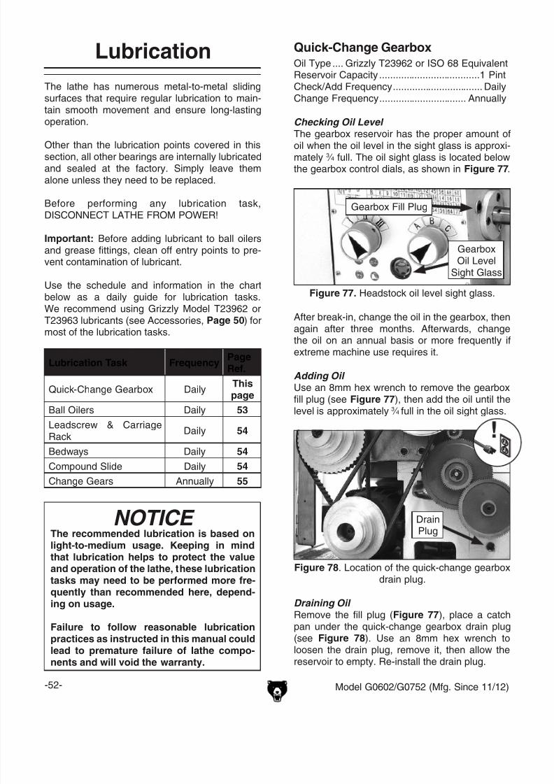
8/21/2019 Griz Lathe G0602
http://slidepdf.com/reader/full/griz-lathe-g0602 54/96-52- Model G0602/G0752 (Mfg. Since 11/12)
The lathe has numerous metal-to-metal slidingsurfaces that require regular lubrication to main-tain smooth movement and ensure long-lastingoperation.
Other than the lubrication points covered in thissection, all other bearings are internally lubricatedand sealed at the factory. Simply leave themalone unless they need to be replaced.
Before performing any lubrication task,DISCONNECT LATHE FROM POWER!
Important: Before adding lubricant to ball oilersand grease fittings, clean off entry points to pre-vent contamination of lubricant.
Use the schedule and information in the chartbelow as a daily guide for lubrication tasks.We recommend using Grizzly Model T23962 orT23963 lubricants (see Accessories, Page 50) formost of the lubrication tasks.
Lubrication
Lubrication Task FrequencyPageRef.
Quick-Change Gearbox DailyThispage
Ball Oilers Daily 53Leadscrew & CarriageRack
Daily 54
Bedways Daily 54
Compound Slide Daily 54
Change Gears Annually 55
NOTICE The recommended lubrication is based on
light-to-medium usage. Keeping in mindthat lubrication helps to protect the valueand operation of the lathe, these lubricationtasks may need to be performed more fre-quently than recommended here, depend-ing on usage.
Failure to follow reasonable lubricationpractices as instructed in this manual couldlead to premature failure of lathe compo-nents and will void the warranty.
Checking Oil Level
The gearbox reservoir has the proper amount ofoil when the oil level in the sight glass is approxi-mately 3 ⁄ 4 full. The oil sight glass is located belowthe gearbox control dials, as shown in Figure 77.
Quick-Change GearboxOil Type .... Grizzly T23962 or ISO 68 EquivalentReservoir Capacity .....................................1 PintCheck/Add Frequency ................................. DailyChange Frequency ................................ Annually
Figure 77. Headstock oil level sight glass.
GearboxOil Level
Sight Glass
Gearbox Fill Plug
After break-in, change the oil in the gearbox, thenagain after three months. Afterwards, changethe oil on an annual basis or more frequently ifextreme machine use requires it.
Adding Oil Use an 8mm hex wrench to remove the gearboxfill plug (see Figure 77), then add the oil until the
level is approximately 3 ⁄ 4 full in the oil sight glass.
Draining Oil Remove the fill plug (Figure 77), place a catchpan under the quick-change gearbox drain plug(see Figure 78). Use an 8mm hex wrench toloosen the drain plug, remove it, then allow thereservoir to empty. Re-install the drain plug.
Figure 78. Location of the quick-change gearboxdrain plug.
DrainPlug

8/21/2019 Griz Lathe G0602
http://slidepdf.com/reader/full/griz-lathe-g0602 55/96Model G0602/G0752 (Mfg. Since 11/12) -53-
Figure 80. Change gear ball oilers.
Ball OilersOil Type .... Grizzly T23963 or ISO 32 EquivalentOil Amount ................................1 or 2 Squirts/FillLubrication Frequency ................................. Daily
This lathe has 10 ball oilers that should be oiledon a daily basis before beginning operation.
Proper lubrication of ball oilers is done with apump-type oil can that has a plastic or rubber-ized cone tip. We do not recommend using metalneedle or lance tips, as they can push the ball toofar into the oiler, break the spring seat, and lodgethe ball in the oil galley.
Lubricate the ball oilers before and after machineuse, and more frequently under heavy use. Whenlubricating ball oilers, first clean the outside sur-face to remove any dust or grime. Push the tip of
the oil can nozzle against the ball oiler to createa hydraulic seal, then pump the oil can once ortwice. If you see sludge and contaminants comingout of the lubrication area, keep pumping the oilcan until the oil runs clear. When finished, wipeaway any excess oil.
Refer to Figures 79–83 to identify the location ofeach ball oiler.
Figure 79. Spindle bearing ball oilers.
Ball Oilers
BallOilers
Figure 83. Leadscrew end bearing ball oilers.
Figure 82. Tailstock ball oiler.
Figure 81. Carriage and cross slide ball oilers.
BallOilers
Ball Oiler
Ball Oiler
Ball Oiler
Ball Oiler

8/21/2019 Griz Lathe G0602
http://slidepdf.com/reader/full/griz-lathe-g0602 56/96-54- Model G0602/G0752 (Mfg. Since 11/12)
Leadscrew & Carriage Rack Oil Type .... Grizzly T23962 or ISO 68 EquivalentOil Amount ......................................... As NeededLubrication Frequency ................................. Daily
Before lubricating the leadscrew and carriagerack (see Figure 84), clean them first with min-
eral spirits. Use a stiff brush to help remove anydebris or grime. Apply a thin coat of oil alongthe length of the carriage rack. Use a stiff brushto make sure oil is applied into the leadscrewthreads.
Note: In some environments, abrasive materialcan become caught in the leadscrew lubricant anddrawn into the half nut. In this case, lubricate theleadscrew with a quality dry lubricant.
Figure 85. Compound bottom slide.
Compound SlideOil Type .... Grizzly T23962 or ISO 68 EquivalentOil Amount ............................................Thin CoatLubrication Frequency ................................. Daily
Use the handwheel to move the compound slideall the way toward you (see Figure 85), then wipe
clean the bottom slide with a rag and mild solvent.Apply the lubricant and move the compound slideback and forth to distribute the oil.
Figure 84. Leadscrew, rack and bedways.
Rack
Leadscrew
Bedways
BedwaysOil Type .... Grizzly T23962 or ISO 68 EquivalentOil Amount ......................................... As NeededLubrication Frequency ................................. Daily
Before lubricating the bedways (see Figure 84),clean it with mineral spirits. Apply a thin coatof oil along the length of the bedway. Move thesteady rest, carriage, and tailstock to access the
entire length of the bedways.
Bottom Slide

8/21/2019 Griz Lathe G0602
http://slidepdf.com/reader/full/griz-lathe-g0602 57/96Model G0602/G0752 (Mfg. Since 11/12) -55-
Change GearsGrease Type ............................................NLGI#2Oil Amount ............................................Thin CoatFrequency............... Annually or When Changing
The change gears, shown in Figure 86, shouldalways have a thin coat of heavy grease to
minimize corrosion, noise, and wear. Wipe awayexcess grease that could be thrown onto theV-belts and reduce optimal power transmissionfrom the motor.
Figure 86. Change gears.
To handle and care for the change gears:
Make sure to clean and lubricate any gears youinstall or change. Be very careful during handlingand storage—the grease coating on the gears willeasily pickup dirt or debris, which can then spreadto the other gears and increase the rate of wear.
Make sure the change gear cover remains installedwhenever possible to keep the gears free of dustor debris from the outside environment.
To lubricate the change gears:
1. DISCONNECT LATHE FROM POWER!
2. Open the change gear cover and remove allthe change gears shown in Figure 86.
3. Clean the change gears thoroughly with min-
eral spirits to remove the old grease. Use asmall brush if necessary to clean between theteeth.
4. Clean the shafts, and wipe away any greasesplatters in the vicinity and on the inside ofthe change gear cover.
5. Using a clean brush, apply a thin layer ofgrease on the gears. Make sure to get greasebetween the gear teeth, but do not fill theteeth valleys.
6. Install the change gears and mesh themtogether with 0.003"–0.008" backlash. Oncethe gears are meshed together, apply a smalldab of grease between them where theymesh together—this grease will be distrib-uted when the gears rotate and re-coat anyareas scraped off during installation.
7. Close the change gear cover before re-con-necting the lathe to power.

8/21/2019 Griz Lathe G0602
http://slidepdf.com/reader/full/griz-lathe-g0602 58/96-56- Model G0602/G0752 (Mfg. Since 11/12)
To prevent the development of rust and corrosion,the lathe must be properly prepared if it will bestored for a long period of time. Doing this willensure the lathe remains in good condition for
later use.
To prepare the lathe for storage:
1. Run the lathe and bring the gearbox reservoirto operating temperature, then drain and refillwith clean oil.
2. DISCONNECT LATHE FROM POWER!
3. Thoroughly clean all unpainted, bare metalsurfaces, then apply a liberal coat of way oil,heavy grease, or rust preventative. Take careto ensure these surfaces are completely cov-ered but that the rust preventative or greaseis kept off of painted surfaces.
4. Lubricate the machine as outlined in theLubrication section beginning on Page 52.Be sure to use an oil can to purge all ball oil-ers and oil passages with fresh oil.
Machine Storage 5. Loosen or remove all belts so they do notbecome stretched during the storage period.(Be sure to place a maintenance note nearthe power button as a reminder that the beltshave been loosened or removed.)
6. Cover the lathe and place it in a dry area thatis out of direct sunlight and away from haz-
ardous fumes, paint, solvents, or gas. Fumesand sunlight can bleach or discolor paint.
7. Every few months do the following:
• Rotate by hand all gear-driven componentsa few times in several gear selections. Thiswill keep the bearings, bushings, gears,and shafts well lubricated and protectedfrom corrosion—especially during the win-ter months.
• Slide the carriage, tailstock, and steadyrest down the lathe bed to make sure thatway spotting is not beginning to occur.

8/21/2019 Griz Lathe G0602
http://slidepdf.com/reader/full/griz-lathe-g0602 59/96Model G0602/G0752 (Mfg. Since 11/12) -57-
Motor & Electrical
Review the troubleshooting and procedures in this section if a problem develops with your machine. If youneed replacement parts or additional help with a procedure, call our Technical Support at (570) 546-9663.Note: Please gather the serial number and manufacture date of your machine before calling.
SECTION 7: SERVICE
Troubleshooting
Symptom Possible Cause Possible Solution
Machine does not
start or a circuit
breaker trips.
1. Emergency stop button engaged or at fault.
2. Spindle direction switch turned OFF or at
fault.
3. Start capacitor at fault.
4. Wall fuse/circuit breaker is blown/tripped;
short in electrical system; start-up load too
high for circuit.
5. Wiring is open/has high resistance.
6. Contactor not getting energized/has poor
contacts.
7. Motor connection wired wrong.
8. Motor spindle direction switch at fault.
9. Inverter/control box at fault (G0752 only).
10. Motor at fault.
1. Rotate button clockwise until it pops out to reset it
for operation; replace if not working properly.
2. Turn spindle direciton switch to FWD or REV.
Ensure switch has correct voltage. Replace if faulty.
3. Test/replace if faulty.
4. Verify circuit is rated for machine amp load;
troubleshoot and repair cause of overload; replace
weak breaker; find/repair electrical short.
5. Check for broken wires or disconnected/corroded
connections, and repair/replace as necessary.
6. Test for power on all legs and contactor operation.
Replace unit if faulty.
7. Correct motor wiring connections (Page 67).
8. Replace switch.
9. Inspect inverter/controller box; replace if faulty.
10. Test/repair/replace.
Loud, repetitious
noise coming from
lathe at or near the
motor.
1. Pulley set screws or keys are missing or
loose.
2. Motor fan is hitting the cover.
1. Inspect keys and set screws. Replace or tighten if
necessary.
2. Tighten fan, shim cover, or replace items.
Motor overheats. 1. Motor overloaded. 1. Allow motor to cool; reduce load on motor.
Motor is loud when
cutting, or bogs
down under load.
1. Excessive depth of cut or feed rate.
2. Spindle speed or feed rate wrong for
cutting operation.
3. Cutting tool is dull.
1. Decrease depth of cut or feed rate.
2. Refer to the feeds and speed charts in Machinery's
Handbook or a speeds and feeds calculator on the
internet.
3. Sharpen or replace the cutting tool.

8/21/2019 Griz Lathe G0602
http://slidepdf.com/reader/full/griz-lathe-g0602 60/96-58- Model G0602/G0752 (Mfg. Since 11/12)
Operation
Symptom Possible Cause Possible Solution
Entire machine
vibrates upon
startup and while
running.
1. Workpiece is unbalanced.
2. Workpiece is hitting stationary object.
3. Loose or damaged V-belt(s).
4. V-belt pulleys are not properly aligned.
5. Chuck or faceplate is unbalanced or not
installed properly.
6. Change gears not aligned or no backlash.
7. Worn or broken gear present.
8. Broken gear or bad bearing.
9. Spindle bearings at fault.
1. Re-install workpiece as centered with the spindle
bore as possible.
2. Stop lathe immediately and correct interference
problem.
3. Re-tension/replace the V-belt(s) as necessary (see
Page 64).
4. Align the V-belt pulleys.
5. Check installation; re-balance chuck or faceplate;
contact a local machine shop for help.
6. Adjust change gears and establish backlash.
7. Inspect gears, and replace if necessary.
8. Replace broken gear or bearing.
9. Reset spindle bearing preload or replace worn
spindle bearings.
Bad surface finish. 1. Wrong spindle speed or feed rate.
2. Dull tooling or poor tool selection.
3. Tool height not at spindle centerline.
4. Too much play in gibs.
1. Adjust for appropriate spindle speed and feed rate.
2. Sharpen tooling or select a better tool for the
intended operation.
3. Adjust tool height to spindle centerline (see Page
40).
4. Tighten gibs (see Page 61).
Tapered tool difficult
to remove from
tailstock quill.
1. Quill is not retracted all the way back into
the tailstock.
2. Contaminants not removed from taper
before inserting into quill.
1. Turn the quill handwheel until it forces the tapered
tool out of quill.
2. Clean the taper and bore, then re-install tool.
Cross slide,
compound rest, or
carriage feed has
sloppy operation.
1. Gibs are out of adjustment.
2. Handwheel is loose or backlash is high.
1. Adjust gibs (see Page 61).
2. Tighten handwheel fasteners, adjust handwheel
backlash to a minimum (see Page 60).
Cross slide,
compound, or
carriage feed
handwheel hard to
move.
1. Dovetail ways loaded with shavings, dust,
or grime.
2. Gib screws are too tight.
3. Backlash setting too tight.
4. Bedways are dry.
1. Clean ways and re-lubricate.
2. Loosen gib screw(s) slightly (see Page 61).
3. Slightly loosen backlash setting (see Page 60).
4. Lubricate bedways/ball oilers.
Cutting tool
or machine
components vibrate
excessively during
cutting.
1. Tool holder not tight enough.
2. Cutting tool sticks too far out of tool holder;
lack of support.
3. Gibs are out of adjustment.
4. Dull cutting tool.
5. Incorrect spindle speed or feed rate.
1. Check for debris, clean, and re-tighten.
2. Re-install cutting tool so no more than 1 ⁄ 3 of the total
length is sticking out of tool holder.
3. Adjust gibs at affected component (see Page 61).
4. Replace or resharpen cutting tool.
5. Use the recommended spindle speed and feed rate.

8/21/2019 Griz Lathe G0602
http://slidepdf.com/reader/full/griz-lathe-g0602 61/96Model G0602/G0752 (Mfg. Since 11/12) -59-
Symptom Possible Cause Possible Solution
Workpiece is
tapered.
1. Headstock and tailstock are not properly
aligned with each other.
1. Re-align the tailstock to the headstock spindle
centerline (see Page 34).
Chuck jaws will
not move or do not
move easily.
1. Chips lodged in the jaws or scroll plate. 1. Remove jaws, clean and lubricate scroll plate and
jaws, then replace jaws.
Carriage will not
feed or is hard to
move.
1. Quick-change gears are not all engaged.
2. Half nut lever engaged.
3. Carriage lock is tightened down.
4. Chips have loaded up on bedways.
5. Bedways are dry and in need of lubrication.
6. Gibs are too tight.
7. Gears or shear pin broken.
1. Adjust gear dials.
2. Disengage half nut lever for manual feeding.
3. Check to make sure the carriage lock bolt is fully
released.
4. Frequently clean away chips that load up during
turning operations and re-lubricate.
5. Lubricate bedways/ball oilers.
6. Loosen gibs screw(s) slightly (see Page 61).
7. Replace gears or shear pin (see Page 62).
Quick-change gear
change dials will not
shift into position.
1. Gears not aligned inside headstock/quick
change gearbox.
1. Rotate spindle by hand with light pressure on the
dial until gear falls into place.

8/21/2019 Griz Lathe G0602
http://slidepdf.com/reader/full/griz-lathe-g0602 62/96-60- Model G0602/G0752 (Mfg. Since 11/12)
Backlash Adjustment
Backlash is the amount of free play felt whilechanging rotation directions with the handwheel.This can be adjusted on the compound rest andcross slide leadscrews. Before beginning any
adjustment, make sure all associated compo-nents are cleaned and lubricated, and the locksare loose.
Reducing backlash to less than 0.002" isimpractical and can lead to accelerated wearto the leadscrew and other components.Avoid the temptation to overtighten thebacklash nut or screw while adjusting.
Compound RestTools Needed: QtyHex Wrench 5mm .............................................. 1Open-End Wrench 10mm .................................. 1
The compound rest backlash is adjusted by loos-ening or tightening the nut and set screw shown in Figure 87 to remove play between the handwheeland the leadscrew collar.
To adjust the backlash, loosen the compound restnut and set screw, turn the handwheel counter-clockwise until the compound rest moves, thentighten the nut until the backlash is approximately0.002"–0.003", as indicated on the graduated dial.Tighten the set screw to secure the setting.
Figure 87. Compound rest backlash adjustment
set screws.
Cross SlideTools Needed: QtyHex Wrench 4mm .............................................. 1Hex Wrench 5mm ............................................. 1Open-End Wrench 14mm .................................. 1
The cross slide backlash is adjusted by loos-
ening the cap screw shown in Figure 88. Thescrew pushes down on a wedge and forces theleadscrew nut apart, taking up lash between thenut and leadscrew.
To adjust the backlash, remove the compoundrest. Then, rock the cross slide handwheel backand forth, and tighten the cap screw slowly untilthe backlash is approximately 0.002"–0.003" asindicated on the graduated dial.
If you end up adjusting the nut too tight, loosenthe cap screw, turn the handwheel back and forthuntil it turns freely—then try again.
Re-install the compound rest when you are fin-ished.
Figure 88. Cross slide backlash adjustment capscrew.
Cap Screw
Nut
Set Screw

8/21/2019 Griz Lathe G0602
http://slidepdf.com/reader/full/griz-lathe-g0602 63/96Model G0602/G0752 (Mfg. Since 11/12) -61-
Gib Adjustment
3. Make adjustments in small and equal incre-ments to the three set screws, then testthe movement of the slide by rotating thehandwheel.
Note: Turning the set screws clockwise willtighten the gib, and turning them counter- clockwise will loosen the gib.
4. When you are satisfied with the gib adjust-ment, keep the set screws from moving andre-tighten the hex nuts to secure the settings.
5. Re-check the movement of the slide and, ifnecessary, repeat Steps 2–4.
Figure 90. Compound slide gib adjustment hexnuts and set screws.
The goal of adjusting the cross slide and com-pound slide gibs is to remove sloppiness or "play"from the ways without making them overly stiffand difficult to move.
In general, loose gibs cause poor finishes andtool chatter; however, over-tightened gibs causepremature wear and make the handwheels dif-ficult to turn.
Tools Needed QtyOpen-End Wrench 8mm.................................... 1Hex Wrench 2.5mm ........................................... 1
To adjust the cross slide and compound slidegibs:
1. DISCONNECT LATHE FROM POWER!
2. Loosen the three hex nuts on the side of theslide (see Figures 89–90).
Figure 89. Cross slide gib adjustment hex nutsand set screws.
Cross SlideAdjustmentFasteners
Compound SlideAdjustmentFasteners

8/21/2019 Griz Lathe G0602
http://slidepdf.com/reader/full/griz-lathe-g0602 64/96-62- Model G0602/G0752 (Mfg. Since 11/12)
The clamping pressure of the half nut is fullyadjustable with a gib that can be loosened ortightened by two set screws. Use this procedureto adjust the half nut if it becomes loose from
wear, or it is too tight for your preferences. A halfnut that is too loose will make it difficult to produceaccurate work; one that is too tight will increasethe rate of wear on itself and the leadscrew.
Tools Needed QtyOpen-End Wrench 8mm.................................... 1Hex Wrench 5mm .............................................. 1Hex Wrench 2.5mm ........................................... 1
To adjust the half nut:
1. DISCONNECT LATHE FROM POWER!
2. Disengage the half nut, then remove thethread dial.
3. Loosen the two adjustment hex nuts shownin Figure 91, then adjust the set screws insmall, even increments so one end of the gibdoes not become tighter than the other.
Half Nut Adjustment
Half-Nut
4. Engage/disengage the half nut several times
and notice how it feels. The adjustment iscorrect when the half nut has a slight dragwhile opening and closing. The movementshould not be too stiff or too sloppy.
5. Repeat Steps 3–4, if necessary, until you aresatisfied with the half nut pressure.
6. While keeping the set screws from moving,re-tighten the hex nuts, then re-install thethread dial.
Figure 91. Typical half nut gib adjustment.
AdjustmentFasteners
Leadscrew Shear PinReplacement
The longitudinal leadscrew is secured to the feedrate gearing in the headstock with the use of a
soft-metal shear pin (see Figure 92). The shearpin is designed to break and disengage powerto the leadscrew to help protect more expensivelathe components if you crash your carriage ortake too large of a cut and overload the lathe.
Contact Grizzly Customer Service at (570) 546-9663 to order a replacement shear pin (Part #P0602815).
Tools Needed QtyHammer ............................................................. 1Punch 2.5mm .................................................... 1
To replace the shear pin:
1. DISCONNECT LATHE FROM POWER!
2. Rotate the leadscrew so the shear pin facesup and down. If the connecting collar rotatesindependently from the leadscrew, then
rotate the collar so the shear pin holes alignwith those in the leadscrew.
3. Use the punch and hammer to drive out thepieces of the old shear pin.
4. Make sure the holes in the collar andleadscrew are aligned, then tap the newshear pin completely through the holes in thecollar and leadscrew.
Figure 92. Longitudinal leadscrew shear pin.
Shear Pin
ConnectingCollar

8/21/2019 Griz Lathe G0602
http://slidepdf.com/reader/full/griz-lathe-g0602 65/96Model G0602/G0752 (Mfg. Since 11/12) -63-
V-Belt Tension &Replacement
V-Belts stretch and wear with use, so check thetension on a monthly basis to ensure optimal
power transmission. Replace the V-belts if theybecome cracked, frayed, or glazed.
On the Model G0602, the low range V-belt ten-sion is controlled by a tensioner between thesecondary drive pulley (B) and spindle (C) pulley.The high range V-belt between the spindle (C)and motor (A) pulleys is tensioned by the motor.
On the Model G0752, V-belt tension is controlledby a tensioner between the spindle and motorpulleys.
Tools Needed QtyOpen-End Wrench 17mm .................................. 1Hex Wrench 5mm .............................................. 1Hex Wrench 8mm .............................................. 1
Tensioning V-BeltTo tension the Model G0602 low range V-beltor Model G0752 V-belt:
1. DISCONNECT LATHE FROM POWER!
2. Open the change gear cover.
3. Loosen the tensioner lock nut (Model G0602)or tensioner lock bolt (Model G0752) shownin Figures 93–94.
4. Push the tensioner against the V-belt to ten-sion it, then secure the tensioner.
The V-belt is correctly tensioned when thereis approximately 1 ⁄ 4" deflection when it ispushed with moderate pressure, as shown in
Figure 95.
Figure 94. Model G0752 tensioner and lock bolt.
—If there is more than 1 ⁄ 4" deflection when theV-belt is pushed with moderate pressure,loosen the tensioner, adjust it so the ten-sion is correct, then secure the tensioner.
5. Secure the change gear cover.
Pulley
Deflection
Pulley
Figure 95. Correct V-belt deflection.
1 ⁄ 4"
Figure 93. Model G0602 tensioner and lock nut.
TensionerLock Nut
Lock Bolt
Tensioner

8/21/2019 Griz Lathe G0602
http://slidepdf.com/reader/full/griz-lathe-g0602 66/96-64- Model G0602/G0752 (Mfg. Since 11/12)
Figure 97. Model G0602 low-range belt.
Model G0752:Loosen the tensioner lock bolt, then pivot thetensioner to the left and secure it temporarily.Remove the V-belt (see Figure 98) and re-installthe new one. Follow Steps 4-5 on Page 63 to ten-sion the belt.
Figure 98. Model G0752 V-Belt.
V-Belt
Tensioner
C
B
To tension the Model G0602 high rangeV-belt:
1. Follow Steps 1–3 in "Tensioning Timing Belt"on Page 65.
2. Lower the motor and re-tighten the mountinghex nuts. The high range V-belt is correctly
tensioned when there is approximately 1 ⁄ 4"deflection when it is pushed with moderatepressure, as shown in Figure 95 on Page 63.
—If there is more than 1 ⁄ 4" deflection whenthe V-belt is pushed with moderate pres-sure, loosen the motor mount nuts, lowerthe motor as needed, then tighten the nuts.
3. Check the timing belt tension (refer to Step 5 of "Tensioning Timing Belt" on Page 65).
4. Secure the change gear cover.
Replacing V-Belt1. DISCONNECT LATHE FROM POWER!
2. Open the change gear cover.
3. Model G0602:
—If the high range belt (Figure 96) needs tobe replaced, loosen the motor mount hex
nuts, (see Figure 99 on Page 65), raisethe motor, and carefully roll the belt off ofpulleys A and C. Install a new V-belt, thenfollow the steps in "To tension the ModelG0602 high range V-belt" above.
Figure 96. Model G0602 high-range belt.
A
C
HighRange Belt
—If the low range belt between pulleys B andC (see Figure 97) needs to be replaced,loosen the tensioner lock nut (see Figure93 on Page 63), move the tensioner down,roll the belt off the pulleys, then re-installthe new V-belt. Follow Steps 4-5 on Page63 to tension the belt.
Lock Bolt
Tensioner

8/21/2019 Griz Lathe G0602
http://slidepdf.com/reader/full/griz-lathe-g0602 67/96Model G0602/G0752 (Mfg. Since 11/12) -65-
Figure 99. Timing belt and motor mount hexnuts.
Timing Belt Tension& Replacement
On the Model G0602 the timing belt transferspower from the motor to the secondary drive pul-
ley (see Figure 99). If the timing belt becomesexcessively worn or damaged, you will need toreplace it.
Tools Needed QtyHex Wrench 5mm .............................................. 1Open-End Wrench 14mm .................................. 1
Tensioning Timing Belt1. DISCONNECT LATHE FROM POWER!
2. Open the change gear cover.
3. Loosen the motor mount hex nuts (seeFigure 99).
Note: It may be more convenient to accessthe motor mount hex nuts if you first remove
the rear splash guard.
—If there is more than 1 ⁄ 4" deflection whenthe belt is pushed with moderate pressure,loosen the motor mount nuts, lower themotor, adjust belt tension as required, thentighten the nuts.
—If the high range V-belt is installed, checkthe V-belt tension. Refer to "To tension theModel G0602 high range V-belt" instruc-tions on Page 64.
6. Secure the change gear cover.
Replacing Timing Belt1. DISCONNECT LATHE FROM POWER!
2. Open the change gear cover.
3. Loosen the four motor mount hex nuts (seeFigure 99) then remove the low or high rangeV-belt (refer to Replacing V-Belt on Page64).
Note: It may be more convenient to accessthe motor mount hex nuts if you first removethe rear splash guard.
4. Raise the motor up, roll the old timing beltoff the pulleys and replace it with a new one,
making sure that the belt teeth are seated inthe pulley indents.
5. Re-install the high or low range V-Belt—depending upon your setup (refer toReplacing V-Belt on Page 64).
6. Tension the timing belt and V-belt. Refer toTensioning Timing-Belt on this page, andthe instructions for tensioning the applicableV-belt on Pages 63– 64.
Pulley
Deflection
Pulley
Figure 100. Correct timing-belt deflection.
1 ⁄ 4"
4. Lower the motor and re-tighten the mountinghex nuts.
TimingBelt
MotorMount
Hex Nuts(2 of 4)
5. Check the timing belt tension: It is correctlytensioned when there is approximately 1 ⁄ 4"deflection when it is pushed with moderatepressure, as shown in Figure 100.

8/21/2019 Griz Lathe G0602
http://slidepdf.com/reader/full/griz-lathe-g0602 68/96-66- Model G0602/G0752 (Mfg. Since 11/12)
SHOCK HAZARD.Working on wiring that is con-nected to a power source is extremely dangerous.
Touching electrified parts will result in personalinjury including but not limited to severe burns,electrocution, or death. Disconnect the powerfrom the machine before servicing electrical com-ponents!
MODIFICATIONS. Modifying the wiring beyondwhat is shown in the diagram may lead to unpre-dictable results, including serious injury or fire.This includes the installation of unapproved after-
market parts.
WIRE CONNECTIONS. All connections mustbe tight to prevent wires from loosening duringmachine operation. Double-check all wires dis-connected or connected during any wiring task toensure tight connections.
CIRCUIT REQUIREMENTS. You MUST followthe requirements at the beginning of this man-ual when connecting your machine to a powersource.
WIRE/COMPONENT DAMAGE. Damaged wiresor components increase the risk of serious per-
sonal injury, fire, or machine damage. If you noticethat any wires or components are damaged whileperforming a wiring task, replace those wires orcomponents.
MOTOR WIRING. The motor wiring shown inthese diagrams is current at the time of printingbut may not match your machine. If you find thisto be the case, use the wiring diagram inside themotor junction box.
CAPACITORS/INVERTERS. Some capacitorsand power inverters store an electrical charge forup to 10 minutes after being disconnected fromthe power source. To reduce the risk of beingshocked, wait at least this long before working oncapacitors.
EXPERIENCING DIFFICULTIES. If you are expe-riencing difficulties understanding the informationincluded in this section, contact our TechnicalSupport at (570) 546-9663.
Wiring Safety Instructions
The photos and diagrams
included in this section are
best viewed in color. You
can view these pages in
color at www.grizzly.com.
These pages are current at the time of printing. However, in the spirit of improvement, we may make chang-es to the electrical systems of future machines. Compare the manufacture date of your machine to the onestated in this manual, and study this section carefully.
If there are differences between your machine and what is shown in this section, call Technical Support at(570) 546-9663 for assistance BEFORE making any changes to the wiring on your machine. An updatedwiring diagram may be available. Note: Please gather the serial number and manufacture date of yourmachine before calling. This information can be found on the main machine label.
SECTION 8: WIRINGmachine

8/21/2019 Griz Lathe G0602
http://slidepdf.com/reader/full/griz-lathe-g0602 69/96Model G0602/G0752 (Mfg. Since 11/12) -67-READ ELECTRICAL SAFETY
ON PAGE 66!
G0602 Wiring Diagram
Ground
Motor 1HP 110V
Ground
Front
View
6 102
8 124
Rear
View
7 113
5 91
13NO 21NC 31NC
14NO 22NC 32 NC
4T2
3L2
Siemens
3TB41
22E KM1
CANSEN LW26-20Start
Button
Switch
E-Stop Button
Switch
Rotary
Switch
U2 V1 W1
V2U1W2
Neutral
Hot
Ground
2
1 NC
MINGERLA125H-BE101C
3
A2
Gnd
L
N
L
4
4
L
L L
L
N
N
V2
V2
N
V1V1
3
4
L
V1
S t a r t C a p a c i t o r
1 5 0 M F D
2 5 0 V A C
R u n C a p a c i t o r
2 0 M F D
4 5 0 V A C
W1
W1
44 NO
6T32T1
43NO
1L1
A1
5L3
N
U1
U1V1
W2
W2
W2
U2
U2
N
110 VAC5-15 Plug
(As Recommended)
Control PanelWiring Box
V1
(Shown from behind)
2
MINGERLA125H-BE101C
3
4 NO
4
4 4
4
L 3
3L

8/21/2019 Griz Lathe G0602
http://slidepdf.com/reader/full/griz-lathe-g0602 70/96-68- Model G0602/G0752 (Mfg. Since 11/12)READ ELECTRICAL SAFETY
ON PAGE 66!
Figure 103. Motor connection detail.
G0602 Electrical Components
Figure 101. Spindle direction switch and ONbutton.
Figure 102. Electrical box.
Figure 105. Magnetic contactor.
Figure 104. Spindle direction switch and
emergency stop switch.

8/21/2019 Griz Lathe G0602
http://slidepdf.com/reader/full/griz-lathe-g0602 71/96Model G0602/G0752 (Mfg. Since 11/12) -69-READ ELECTRICAL SAFETY
ON PAGE 66!
G0752 Wiring Box Diagram
21NC 31NC
14NO 22NC 32 NC
4T2
3L2
Siemens
3TB41
22E KM1
A2
44 NO
6T32T1
43NO
5L3
13NO
Contactor
1
2 A
2
4
6
OMRON
MY2N-J 220V
5
12L1 N1
L1 N1
L N
L N
14 13
9
1
Relay
MI1 MI3
MI2 MI4
MI5 DCM 24VAC1
10VRS-485
Port
MI6 DCM ACM
AFM
AVI
M01
MCM
RA RC
RB
AVI
ACI
NPN
PNP
R/L1
READ Y RUN FAU LT ON
1 2 3
U/T1 V/T2 W/T3 +/B1 B2
S/L2 T/L3
DeltaVFD007E11A
VS Drive
1
Transformer
BEIJING AOHENGDA ELECTRICAL
JBK5-40VA
PE 0 1 10 2 20
0 24
V1
W1N1
N1
L1
L1
DCM
10V
10V
AVI
AVI
ACM
ACM
1L1
A1
3
N1L1
DCM
L N
PE
U1 V1 W1
U1
PE
PE
N1
N1
N1
L1
0
L1
5
8
80
PE
L
N
2
4
3
1
5
5
4
0
Wiring Box
DCM
LN
L
L
N
M1
M1
M2
M2 DCM
PE
PE
To Left MotorJunction BoxPage 73
To Circuit BoardPage 71
To Variable SpeedSwitch Page 71
To Spindle DirectionSwitch Page 71
To Control PanelPage 71
To Right MotorJunction BoxPage 73
To PowerSupplyPage 73

8/21/2019 Griz Lathe G0602
http://slidepdf.com/reader/full/griz-lathe-g0602 72/96-70- Model G0602/G0752 (Mfg. Since 11/12)READ ELECTRICAL SAFETY
ON PAGE 66!
Figure 106. G0752 electrical box.
G0752 Wiring Box Components

8/21/2019 Griz Lathe G0602
http://slidepdf.com/reader/full/griz-lathe-g0602 73/96Model G0602/G0752 (Mfg. Since 11/12) -71-READ ELECTRICAL SAFETY
ON PAGE 66!
G0752 Control Panel Wiring Diagram
1 NC
LA252HBE102C
2 3 NO
4
LA252HBE101C L A 2 5 2 H B E 1 0 1 C
L A 2 5 2 H B E 1 0 1 C
L A 2 5 2 H B E 1 0 2 C
L A 2 5 2 H B E 1 0 2 C
2
2
4
4
VS Switch
RPM Display
SpindleSpeed
Sensor
Spindle Speed
Circuit Board
SpindleDirection
Switch
OFF ButtonSwitch
ON ButtonSwitch
E-StopButton Switch
(Viewed from Behind)
Control Panel
WX14-124K7
3 NO
3 NO
1 NC
1 NC
(Bottom)(Top)
COM
4
Ground
33
3
33
33
22
2
P EPE
M 1M1
M 2M2
M2
10V
A V IAVI
A C MACM
4
PE
1 NC
LA252HBE102C
2
44
5
11 11
11
1
4
D C MDCM
DCM
5
M1
See Figure 107, on Page 72
See Figure 110, Page 72
See Figure 108, Page 72
See
Figure 109,Page 72
To Wiring Box Page 69
To Wiring Box Page 69
To Wiring Box Page 69
See Figure 112, on Page 72

8/21/2019 Griz Lathe G0602
http://slidepdf.com/reader/full/griz-lathe-g0602 74/96-72- Model G0602/G0752 (Mfg. Since 11/12)READ ELECTRICAL SAFETY
ON PAGE 66!
G0752 Control Panel Components
Figure 107. Control panel.
Figure 108. RPM display.
Figure 111. Right junction box.
Figure 109. Variable speed potentiometer.
Figure 110. Spindle speed circuit board.
Figure 112. Spindle speed sensor.
E-Stop
ButtonSwitch
ON ButtonSwitch
OFFButtonSwitch
SpindleDirectionSwitch

8/21/2019 Griz Lathe G0602
http://slidepdf.com/reader/full/griz-lathe-g0602 75/96Model G0602/G0752 (Mfg. Since 11/12) -73-
Figure 114. Right motor junction box.Figure 113. Left motor junction box.
G0752 Motor Wiring Diagram
Motor 1HP 220V 3PH
Motor Fan
110V 30W 1PH
Ground
Neutral
Hot
Ground
110 VAC5-15 Plug
(As Recommended)
U1W1
N1 L1
PEL N
V1
PE
To Wiring Box Page 69
To Wiring Box Page 69
To Wiring Box Page 69

8/21/2019 Griz Lathe G0602
http://slidepdf.com/reader/full/griz-lathe-g0602 76/96-74- Model G0602/G0752 (Mfg. Since 11/12)
Spindle & Drive Belt
SECTION 9: PARTS
1
25
67
8
10 11
1314
15
16
17
18
19
19-1
20 21
22
2324
25
26
27
54
55
55-1
28
29
30
3132
3334
35
36
3737
3738
39
4041
4142 4243
40
44
4546
4748
49
51
5253
12
54-4
55-2
54-3
57
3
56
54-2
60
62
64
6970
63
54-1
LEFT REAR VIEW
(G0602)
(G0752)
(G0602)
(G0602) (G0752)
(G0602)(G0752)
51
13
55-3
71
72

8/21/2019 Griz Lathe G0602
http://slidepdf.com/reader/full/griz-lathe-g0602 77/96Model G0602/G0752 (Mfg. Since 11/12) -75-
Spindle & Drive Belt PartsREF PART # DESCRIPTION REF PART # DESCRIPTION
1 P0602001 HEADSTOCK REAR COVER 37 P0752037 MOTOR PULLEY (G0752)
2 P0602002 PHLP HD SCR M4-.7 X 6 38 P0602038 KEY 6 X 6 X 40
3 P0602003 DEAD CENTER MT#4 39 P0602039 SPACER
5 P0602005 CAP SCREW M6-1 X 25 40 P0602040 STANDOFF STUD M10-1.5 X 50, 15, 25 (G0602)
6 P0602006 FLAT WASHER 6MM 40 P0752040 CAP SCREW M10-1.5 X 20 (G0752)
7 P0602007 COMPRESSION SPRING 41 P0602041 MOUNTING PLATE8 P0602008 CLAMP 42 P0602042 FLAT WASHER 10MM
10 P0602010 CAP SCREW M6-1 X 25 43 P0602043 HEX NUT M10-1.5 (G0602)
11 P0602011 SPINDLE 44 P0602044 TENSIONER ROLLER SHAFT
12 P0602012 KEY 10 X 10 X 55 45 P0602045 BALL BEARING 6001-2RS
13 P0602013 SPACER 46 P0602046 TENSIONER ROLLER
14 P0602014 TAPERED ROLLER BEARING 32009 48 P0602048 EXT RETAINING RING 12MM
15 P0602015 HEADSTOCK 49 P0602049 CHANGE GEAR COVER
16 P0602016 CAP SCREW M8-1.25 X 20 51 P0602051 HEX NUT M5-.8
17 P0602017 TAPERED ROLLER BEARING 32009 52 P0602052 SPINDLE COVER
18 P0602018 CAP SCREW M6-1 X 20 53 P0602053 PHLP HD SCR M5-.8 X 12
19 P0602019 SPACER 54 P0602054 3-JAW CHUCK 5"
19 P0752019 SPEED SENSOR RING W/MAGNETS 54-1 P0602054-1 3-JAW CHUCK JAW INT 3-PC SET
20 P0602020 GEAR 40T PLASTIC 54-2 P0602054-2 CHUCK BACKPLATE
21 P0602021 V-BELT M-27.5 3L275 (G0602) 54-3 P0602054-3 3-JAW CHUCK KEY22 P0602022 PULLEY C 54-4 P0602054-4 3-JAW CHUCK JAW EXT 3-PC SET
23 P0602023 V-BELT M-33 3L330 55 P0602055 4-JAW CHUCK 6.5"
24 P0602024 SPANNER NUT 37MM 55-1 P0602055-1 4-JAW CHUCK JAWS 4-PC SET
25 P0602025 BRACKET PLATE 55-2 P0602055-2 4-JAW CHUCK KEY
26 P0602026 LOCK WASHER 10MM 55-3 P0602055-3 4-JAW CHUCK BACKPLATE
27 P0602027 HEX NUT M10-1.5 56 P0602056 FACEPLATE 8"
28 P0602028 FLAT WASHER 10MM 57 P0602057 DEAD CENTER MT#3
29 P0602029 CAP SCREW M5-.8 X 10 60 P0602060 TOOL BOX, EMPTY
30 P0602030 FLAT WASHER 5MM 62 P0602062 HEX WRENCH SET (2.5,3,4,5,6MM)
31 P0602031 GEAR SHAFT 63 P0602063 WRENCH SET (8-10, 12-14, 17-19MM)
32 P0602032 TIMING BELT 263L (G0602) 64 P0602064 BOTTLE FOR OIL
33 P0602033 BALL BEARING 6001ZZ (G0602) 69 P0602069 STANDARD SCREWDRIVER #1
34 P0602034 TIMING PULLEY (G0602) 70 P0602070 PHILLIPS SCREWDRIVER #1
35 P0602035 INT RETAINING RING 12MM (G0602) 71 P0602071 SPINDLE CLAMP
36 P0602036 SPACER 72 P0602072 CAP SCREW M6-1 X 20
37 P0602037 PULLEY A (G0602)
Please Note: We do our best to stock replacement parts whenever possible, but we cannot guarantee that all parts shown here
are available for purchase. Call (800) 523-4777 or visit our online parts store at www.grizzly.com to check for availability.

8/21/2019 Griz Lathe G0602
http://slidepdf.com/reader/full/griz-lathe-g0602 78/96-76- Model G0602/G0752 (Mfg. Since 11/12)
Apron
101
102103
104105
106
107
108 109
110
111
112
113
114
115116 117
118119
120
121
122
123
124
125
126
127
128
129
130
131
132
133
134
135
136
137
138
139
140
141142
126-1
G0602 Only
132
133
143
144
145
134
146
136
G0752 Only
REF PART # DESCRIPTION REF PART # DESCRIPTION
101 PRP19M ROLL PIN 4 X 14 126 P0602126 THREAD DIAL BODY
102 P0602102 HALF-NUT 2-PC 126-1 P0602126-1 THREAD DIAL ASSY
103 P0602103 DOWEL PIN 5 X 12 127 P0602127 SIDE GEAR 48T
104 P0602104 GEAR SHAFT 128 PW01M FLAT WASHER 8MM
105 P0602105 GEAR 129 PN03M HEX NUT M8-1.25
106 PRP73M ROLL PIN 4 X 30 130 PSS02M SET SCREW M6-1 X 6
107 P0602107 APRON CASTING 131 P0602131 COMPRESSION SPRING
108 PCAP23M CAP SCREW M4-.7 X 12 132 P0602132 CARRIAGE HANDWHEEL HANDLE
109 P0602109 HALF-NUT GIB 133 P0602133 CARRIAGE HANDWHEEL (G0602)
110 P0602110 DOWEL PIN 4 X 16 133 P0752133 CARRIAGE HANDWHEEL (G0752)
111 PSS34M SET SCREW M5-.8 X 16 134 PRP04M ROLL PIN 4 X 24 (G0602)
112 PSS12M SET SCREW M6-1 X 25 134 PSS04M SET SCREW M6-1 X 12 (G0752)
113 PN06M HEX NUT M5-.8 135 PSS131M SET SCREW M6-1 X 12 CONE-PT
114 PSS04M SET SCREW M6-1 X 12 136 P0602136 GEAR SHAFT (G0602)
115 P0602115 HALF-NUT LEVER HUB 136 P0752136 GEAR SHAFT (G0752)
116 P0602116 HALF-NUT LEVER STUD 137 PFH29M FLAT HD SCR M6-1 X 10
117 P0602117 HALF-NUT LEVER HANDLE 138 PW03M FLAT WASHER 6MM
118 PSTB004M STEEL BALL 5MM 139 P0602139 HALF-NUT INDICATOR PLATE
119 PCAP85M CAP SCREW M6-1 X 6 140 P0602140 LOCK CAM SHAFT
120 P0602120 THREAD DIAL 141 P0602141 THREADED DIAL PLATE
121 PRIV001M RIVET 2 X 5MM STEEL FLUTED 142 P0602142 HALF-NUT BRACKET
122 P0602122 POINTER 143 P0752143 PLATE SPRING (G0752)
123 P0602123 SHAFT 144 P0752144 GRADUATED DIAL (G0752)
124 PK39M KEY 3 X 3 X 10 145 PRP59M ROLL PIN (G0752)
125 PCAP83M CAP SCREW M6-1 X 55 146 PK103M KEY 3 X 3 X 12 (G0752)

8/21/2019 Griz Lathe G0602
http://slidepdf.com/reader/full/griz-lathe-g0602 79/96Model G0602/G0752 (Mfg. Since 11/12) -77-
201
202
203
204
205
206
207
208
209
210
211
212
213
214
215
216
217
218
219
220
221
222
223
224
225
226
227
228
229
230 231
208
220A
Tool Post & Compound Rest
REF PART # DESCRIPTION REF PART # DESCRIPTION
201 P0602201 COMPOUND REST 217 PB26M HEX BOLT M8-1.25 X 30
202 P0602202 SWIVEL BASE 218 P0602218 TOOL POST HANDLE
203 P0602203 COMPOUND REST GIB 219 P0602219 TOOL POST HANDLE HUB
204 P0602204 CLAMPING RING 220A P0602220A 4-WAY TOOL POST ASSEMBLY
205 P0602205 GRADUATED DIAL 220 P0602220 TOOL REST
206 P0602206 BARREL NUT 221 P0602221 HUB SPACER
207 P0602207 DOWEL PIN 222 P0602222 TOOL REST SLIDE PLATE
208 P0602208 TOOL POST BOLT 223 P0602223 COMPOUND REST LEADSCREW
209 PW01M FLAT WASHER 8MM 224 P0602224 LEADSCREW MOUNT
210 P0602210 DOWEL PIN 225 P0602225 GRADUATED DIAL
211 P0602211 COMPRESSION SPRING 226 P0602226 COMPOUND REST HANDWHEEL
212 PCAP13M CAP SCREW M8-1.25 X 30 227 P0602227 COMPOUND HANDWHEEL HANDLE
213 PCAP31M CAP SCREW M8-1.25 X 25 228 PK03M KEY 3 X 3 X 8
214 PCAP26M CAP SCREW M6-1 X 12 229 P0602229 POINTER
215 PSS34M SET SCREW M5-.8 X 16 230 P0602230 THREADED COLLAR
216 PN06M HEX NUT M5-.8 231 PSS17M SET SCREW M8-1.25 X 6

8/21/2019 Griz Lathe G0602
http://slidepdf.com/reader/full/griz-lathe-g0602 80/96-78- Model G0602/G0752 (Mfg. Since 11/12)
Tailstock
301
302
303
304
305
306
307
308
309
310
311
312
314
315
316317
318
319
320
321
322
323
324
325
326
313
314
319
300
REF PART # DESCRIPTION REF PART # DESCRIPTION
300 P0602300 COMPLETE TAILSTOCK ASSY 314 PSS21M SET SCREW M8-1.25 X 25
301 P0602301 TAILSTOCK QUILL 315 P0602315 TAILSTOCK HANDWHEEL HANDLE
302 P0602302 TAILSTOCK LEADSCREW 316 P0602316 UPPER OFFSET PLATE
303 P0602303 BUSHING 317 PK39M KEY 3 X 3 X 10
304 P0602304 HANDWHEEL SCALE PLATE 318 PLN05M LOCK NUT M10-1.5
305 P0602305 TAILSTOCK HANDWHEEL 319 PRIV001M RIVET 2 X 5MM STEEL FLUTED
306 P0602306 LEVER BOLT M12-1.75 X 50 320 P0602320 BALL OILER 10MM
307 P0602307 BARREL NUT M12-1.75 321 P0602321 CLAMPING PLATE
308 PSS04M SET SCREW M6-1 X 12 322 PN09M HEX NUT M12-1.75
309 P0602309 GRADUATED DIAL 323 PB158M HEX BOLT M12-1.75 X 90310 P0602310 TAILSTOCK HANDWHEEL POINTER 324 PW06M FLAT WASHER 12MM
311 P0602311 HANDWHEEL BUSHING 325 PSS26M SET SCREW M5-.8 X 6
312 P0602312 TAILSTOCK BODY 326 P0602326 LOWER OFFSET PLATE
313 P0602313 TAILSTOCK BASE

8/21/2019 Griz Lathe G0602
http://slidepdf.com/reader/full/griz-lathe-g0602 81/96Model G0602/G0752 (Mfg. Since 11/12) -79-
Bed & Leadscrew
401
402
403
404405
406407 408
409
410
411
412
413414
415
REF PART # DESCRIPTION REF PART # DESCRIPTION
401 P0602401 BED 409 P0602409 BACK SPLASH402 P0602402 RACK 410 P0602410 STUD-SE M10-1.5 X 45, 35
403 PCAP33M CAP SCREW M5-.8 X 12 411 PN02M HEX NUT M10-1.5
404 P0602404 LONGITUDINAL LEADSCREW 412 PSS44M SET SCREW M8-1.25 X 40
405 P0602405 LEADSCREW END BRACKET 413 PW01M FLAT WASHER 8MM
406 P0602406 BALL OILER 6MM 414 PN03M HEX NUT M8-1.25
407 PCAP02M CAP SCREW M6-1 X 20 415 P0602415 CHIP PAN
408 PLN05M LOCK NUT M10-1.5

8/21/2019 Griz Lathe G0602
http://slidepdf.com/reader/full/griz-lathe-g0602 82/96-80- Model G0602/G0752 (Mfg. Since 11/12)
Steady Rest & Follow Rest
501
502
503
504
505
506
507 508
509
511
512
513
514
511A
515
516
517
518
510501A
REF PART # DESCRIPTION REF PART # DESCRIPTION
501A P0602501A STEADY REST ASSEMBLY 510 PN09M HEX NUT M12-1.75
501 P0602501 STEADY REST CASTING 511A P0602511A FOLLOW REST ASSEMBLY
502 P0602502 FINGER 511 P0602511 FOLLOW REST CASTING
503 P0602503 SHOULDER T-BOLT 512 P0602502 FINGER
504 PLW03M LOCK WASHER 6MM 513 P0602503 SHOULDER T-BOLT
505 PN01M HEX NUT M6-1 514 P0602506 ADJUSTING SCREW
506 P0602506 ADJUSTING SCREW 515 PN01M HEX NUT M6-1
507 P0602507 CLAMPING PLATE 516 PLW03M LOCK WASHER 6MM
508 PB125M HEX BOLT M12-1.75 X 65 517 PCAP40M CAP SCREW M8-1.25 X 35
509 PW06M FLAT WASHER 12MM 518 PW01M FLAT WASHER 8MM

8/21/2019 Griz Lathe G0602
http://slidepdf.com/reader/full/griz-lathe-g0602 83/96Model G0602/G0752 (Mfg. Since 11/12) -81-
G0602 Motor & Electrical
601
602
603
604
607
608
610
611V2
611V2-2
611V2-3
611V2-4
611V2-6
612
615
617
616
611V2-5
611V2-7
611V2-1
618
620
619
621
REF PART # DESCRIPTION REF PART # DESCRIPTION
601 P0602601 ELECTRICAL CABINET 611V2-5 P0602611V2-5 CAPACITOR COVER
602 PCAP06M CAP SCREW M6-1 X 25 611V2-6 P0602611V2-6 POWER CORD 14G 3W 60" 5-15P
603 PLW03M LOCK WASHER 6MM 611V2-7 P0602611V2-7 MOTOR JUNCTION BOX
604 P0602604 ELECTRICAL CABINET COVER 612 PW05M FLAT WASHER 4MM
607 P0602607 STRAIN RELIEF NUT 615 P0602615 STRAIN RELIEF M20-1.5
608 P0602608 STRAIN RELIEF M25-1.5 616 P0602616 STRAIN RELIEF NUT610 PS17M PHLP HD SCR M4-.7 X 6 617 P0602617 CONTACTOR SIEMENS 3TB41 22E 110V
611V2 P0602611V2 MOTOR 1HP 110V 1-PH ALUM BDY V2.09.08 618 P0602618 E-STOP BUTTON MINGER LA125H-BE102C
611V2-1 P0602611V2-1 MOTOR FAN 619 P0602619 ON PUSH BUTTON MINGER LA125H-BE101C
611V2-2 P0602611V2-2 MOTOR FAN COVER 620 P0602620 ROTARY SWITCH CANSEN LW26-20 M09T/3
611V2-3 PC150 S CAPACITOR 150M 125V 621 P0602621 G0602 CONTROL PANEL
611V2-4 P0602611V2-4 R CAPACITOR 20M 400V

8/21/2019 Griz Lathe G0602
http://slidepdf.com/reader/full/griz-lathe-g0602 84/96-82- Model G0602/G0752 (Mfg. Since 11/12)
G0752 Motor & Electrical
611
611-1
611-2
611-3 611-4
611-6
602
601
604603
607
617
618
619
630
631
632633
620
634
621608
610
612
622
623
624
627
628
629
626
625
4
6
KAIDYF08A
5
1
REF PART # DESCRIPTION REF PART # DESCRIPTION
601 P0752601 ELECTRICAL CABINET 619 P0752619 TERMINAL POST
602 PCAP06M CAP SCREW M6-1 X 25 620 P0752620 VS DRIVE DELTA VFD007E11A
603 PLW03M LOCK WASHER 6MM 621 P0752621 VFD-E USER MANUAL
604 P0752604 ELECTRICAL CABINET COVER 622 P0752622 E-STOP BUTTON MINGER LA125H-BE101C-102C
607 P0602607 STRAIN RELIEF NUT 623 P0752623 ON PUSH BUTTON MINGER LA125H-BE102C
608 P0602608 STRAIN RELIEF M25-1.5 624 P0752624 SPINDLE DIRECTION SWITCH LA125H-BE102C
610 PS17M PHLP HD SCR M4-.7 X 6 625 P0752625 G0752 CONTROL PANEL
611 P0752611 MOTOR 1HP 220V 3-PH 626 P0752626 OFF PUSH BUTTON MINGER LA125H-BE101C
611-1 P0752611-1 MOTOR FAN 627 P0752627 RPM DISPLAY UNIT
611-2 P0752611-2 MOTOR FAN COVER 628 P0752628 POTENTIOMETER WX14-12 4K7
611-3 P0752611-3 RIGHT MOTOR JUNCTION BOX COVER 629 P0752629 SPINDLE SPEED SENSOR
611-4 P0752611-4 LEFT MOTOR JUNCTION BOX COVER 630 P0752630 RELAY OMRON MY2N-J 220V
611-6 P0602611-6 POWER CORD 16G 3W 60" 5-15P 631 P0752631 FUSE 2A 250V
612 PW05M FLAT WASHER 4MM 632 P0752632 FUSE HOLDER
617 P0602617 CONTACTOR SIEMENS 3TB41 22E 110V 633 P0752633 TERMINAL POST MOUNTING BRACKET
618 P0752618 TRANSFORMER BAEEC JBK5-40VA 634 P0752634 GROUNDING BAR

8/21/2019 Griz Lathe G0602
http://slidepdf.com/reader/full/griz-lathe-g0602 85/96Model G0602/G0752 (Mfg. Since 11/12) -83-
701
702703
704
706
707
708
711
712
713
714 715
716
717718719
720
723
724
725
726727
729
728
730
731
732
733
734
735
736
737
739
740
741
721
722
REF PART # DESCRIPTION REF PART # DESCRIPTION
701 PSS01M SET SCREW M6-1 X 10 723 P0602723 GEAR 104T
702 P0602715 KEYED BUSHING 724 PW03M FLAT WASHER 6MM
703 P0602703 GEAR 60T PLASTIC 725 PCAP85M CAP SCREW M6-1 X 6
704 P0602704 GEAR 27T CAST-IRON 726 PLW04M LOCK WASHER 8MM
706 P0602706 GEAR SHAFT 727 PCAP12M CAP SCREW M8-1.25 X 40
707 PEC10M E-CLIP 9MM 728 P0602728 GEAR 36T
708 P0602708 BALL OILER 6MM 729 P0602729 GEAR 36T
711 P0602711 BRACKET 730 P0602730 GEAR 40T
712 P0602712 T-NUT 731 P0602731 GEAR 44T
713 P0602713 SPACER WASHER 732 P0602732 GEAR 46T
714 P0602714 GEAR SHAFT 733 P0602733 GEAR 48T
715 P0602715 KEYED BUSHING 734 P0602734 GEAR 52T
716 P0602716 GEAR 127T 735 P0602735 GEAR 45T
717 P0602717 GEAR 56T 736 P0602736 GEAR 56T
718 P0602718 GEAR SHAFT CLIP 737 P0602737 GEAR 60T
719 P0602708 BALL OILER 6MM 738 P0602703 GEAR 60T PLASTIC
720 P0602720 BUSHING 739 P0602739 GEAR 104T
721 PK97M KEY 4 X 4 X 14 740 P0602740 GEAR 120T
722 P0602722 SPACER RING 741 P0602741 GEAR 127T
Change Gears

8/21/2019 Griz Lathe G0602
http://slidepdf.com/reader/full/griz-lathe-g0602 86/96-84- Model G0602/G0752 (Mfg. Since 11/12)
Gearbox
801
802 803
804
806
807
808
809
810
811
812
813
814
815
816
817818
819
820
821
822
823
824
825
826
828
829
830
831
832
833
834
835
836
837
838
839
840
841842
843
844 845
846847
848
849
850
805
805
802
827
822
822
820
822
823

8/21/2019 Griz Lathe G0602
http://slidepdf.com/reader/full/griz-lathe-g0602 87/96Model G0602/G0752 (Mfg. Since 11/12) -85-
REF PART # DESCRIPTION REF PART # DESCRIPTION
801 P0602801 PLUG 826 P0602826 COLLAR
802 P0602802 O-RING 827 PK132M KEY 4 X 4 X10
803 P0602803 BUSHING 828 P0602828 GEAR SHAFT
804 P0602804 CLUSTER GEAR 30/36/33T 829 P0602829 GEAR 33T
805 PK133M KEY 4 X 4 X 50 830 P0602830 GEAR 30T
806 P0602806 GEAR SHAFT 831 P0602831 GEAR 35T
807 P0602807 BUSHING 832 P0602832 FLANGE
808 P0602808 CLUSTER GEAR 22/44/33T 833 PCAP01M CAP SCREW M6-1 X 16
809 P0602809 CLUSTER GEAR PLUG 834 P0602834 SHIFT FORK
810 PCAP50M CAP SCREW M5-.8 X 10 835 P0602835 FRONT GEARBOX COVER
811 P0602811 REAR GEARBOX COVER 836 PRP05M ROLL PIN 5 X 30
812 P0602812 FILL PLUG 3/8" NPT 837 P0602837 COMPRESSION SPRING
813 P0602813 GEAR BOX CASE 838 P0602838 SIGHT GLASS A16
814 P0602814 DRAIN PLUG 3/8" NPT 839 P0602839 POINTER DISC
815 P0602815 SHEAR PIN 5 X 20 840 PSS01M SET SCREW M6-1 X 10
816 P0602816 LEADSCREW CONNECTING COLLAR 841 PSTB004M STEEL BALL 5MM
817 P0602817 SHEAR PIN 5 X 20 842 P0602842 SHIFT HUB
818 PCAP26M CAP SCREW M6-1 X 12 843 PSS01M SET SCREW M6-1 X 10
819 P0602819 FLANGE 844 PCAP37M CAP SCREW M6-1 X 50
820 P6202-OPEN BALL BEARING 6202-OPEN 845 PCAP02M CAP SCREW M6-1 X 20
821 P0602821 GEAR 33T 846 P0602846 O-RING 1.8 X 6.7
822 PR05M EXT RETAINING RING 15MM 847 P0602847 SHAFT
823 PK65M KEY 4 X 4 X 8 848 PRP03M ROLL PIN 5 X 20
824 P0602824 GEAR SHAFT 22T 849 P0602849 SHIFT LEVER
825 P0602825 GEAR 44T 850 P0602850 SHIFT FORK
Gearbox Parts List

8/21/2019 Griz Lathe G0602
http://slidepdf.com/reader/full/griz-lathe-g0602 88/96-86- Model G0602/G0752 (Mfg. Since 11/12)
Cross Slide & Carriage
901
902A
903
904
905
906
907
908
909
910
911
912913
914
915
916
917
918
919
920
921
922
923
924
925
926
927
928
929
930
931
932
933
934
935
936937938
939
REF PART # DESCRIPTION REF PART # DESCRIPTION
901 P0602901 SADDLE 921 P0602921 DOWEL PIN
902A P0602902A CROSS SLIDE W/O T-SLOTS V2.08.07 922 PSS34M SET SCREW M5-.8 X 16
903 P0602903 CROSS SLIDE GIB 923 PN06M HEX NUT M5-.8
904 P0602904 CROSS SLIDE LEADSCREW NUT 924 P0602924 SADDLE TENSION BAR
905 P0602905 CROSS SLIDE LEADSCREW 925 PW03M FLAT WASHER 6MM
906 P0602906 LEADSCREW BRACKET 926 PCAP01M CAP SCREW M6-1 X 16
907 PCAP31M CAP SCREW M8-1.25 X 25 927 P0602927 SADDLE CLAMP PLATE
908 P0602908 INDICATOR PLATE 928 PSS25M SET SCREW M6-1 X 20
909 PRIV001M RIVET 2 X 5MM STEEL FLUTED 929 PN01M HEX NUT M6-1
910 P0602910 GRADUATED DIAL 930 PCAP48M CAP SCREW M6-1 X 35
911 PK105M KEY 3 X 3 X 6 931 P0602931 V-WAY WIPER
912 P0602912 SPRING PLATE 932 P0602932 V-WAY WIPER COVER
913 P0602913 CROSS SLIDE HANDWHEEL 933 PS07M PHLP HD SCR M4-.7 X 8
914 P0602914 HANDWHEEL HEX NUT 934 P0602934 STRAIGHT WAY WIPER
915 PSS17M SET SCREW M8-1.25 X 6 935 P0602935 STRAIGHT WAY WIPER COVER
916 P0602916 CROSS SLIDE HANDWHEEL HANDLE 936 P0602936 BALL OILER 6MM
917 P0602917 SLIDE BLOCK 937 PCAP40M CAP SCREW M8-1.25 X 35
918 P0602918 CHIP GUARD 938 PCAP48M CAP SCREW M6-1 X 35
919 PCAP26M CAP SCREW M6-1 X 12 939 P0602939 HANDLE SCREW
920 PSS11M SET SCREW M6-1 X 16

8/21/2019 Griz Lathe G0602
http://slidepdf.com/reader/full/griz-lathe-g0602 89/96

8/21/2019 Griz Lathe G0602
http://slidepdf.com/reader/full/griz-lathe-g0602 90/96

8/21/2019 Griz Lathe G0602
http://slidepdf.com/reader/full/griz-lathe-g0602 91/96Model G0602/G0752 (Mfg. Since 11/12) -89-
SECTION 10: APPENDIXmachine
G0602 Charts

8/21/2019 Griz Lathe G0602
http://slidepdf.com/reader/full/griz-lathe-g0602 92/96
G0752 Charts

8/21/2019 Griz Lathe G0602
http://slidepdf.com/reader/full/griz-lathe-g0602 93/96
Name _____________________________________________________________________________
Street _____________________________________________________________________________
City _______________________ State _________________________ Zip _____________________
Phone # ____________________ Email _________________________________________________
Model # ____________________ Order # _______________________ Serial # __________________
WARRANTY CARD
The following information is given on a voluntary basis. It will be used for marketing purposes to help us develop
better products and services. Of course, all information is strictly confidential.
1. How did you learn about us? ____ Advertisement ____ Friend ____ Catalog ____ Card Deck ____ Website ____ Other:
2. Which of the following magazines do you subscribe to?
3. What is your annual household income? ____ $20,000-$29,000 ____ $30,000-$39,000 ____ $40,000-$49,000 ____ $50,000-$59,000 ____ $60,000-$69,000 ____ $70,000+
4. What is your age group? ____ 20-29 ____30-39 ____ 40-49
____ 50-59 ____60-69 ____ 70+
5. How long have you been a woodworker/metalworker? ____ 0-2 Years ____ 2-8 Years ____ 8-20 Years ____20+ Years
6. How many of your machines or tools are Grizzly? ____ 0-2 ____ 3-5 ____ 6-9 ____10+
7. Do you think your machine represents a good value? _____Yes _____No
8. Would you recommend Grizzly Industrial to a friend? _____Yes _____No
9. Would you allow us to use your name as a reference for Grizzly customers in your area? Note: We never use names more than 3 times. _____Yes _____No
10. Comments: _____________________________________________________________________
_________________________________________________________________________________
_________________________________________________________________________________
_________________________________________________________________________________
____ Cabinetmaker & FDM____ Family Handyman____ Hand Loader
____ Handy____ Home Shop Machinist____ Journal of Light Cont.____ Live Steam____ Model Airplane News____ Old House Journal____ Popular Mechanics
____ Popular Science____ Popular Woodworking____ Precision Shooter
____ Projects in Metal____ RC Modeler____ Rie____ Shop Notes____ Shotgun News____ Today’s Homeowner____ Wood
____ Wooden Boat____ Woodshop News____ Woodsmith
____ Woodwork____ Woodworker West____ Woodworker’s Journal____ Other:

8/21/2019 Griz Lathe G0602
http://slidepdf.com/reader/full/griz-lathe-g0602 94/96
TAPE ALONG EDGES--PLEASE DO NOT STAPLE
FOLD ALONG DOTTED LINE
FOLD ALONG DOTTED LINE
GRIZZLY INDUSTRIAL, INC.
P.O. BOX 2069
BELLINGHAM, WA 98227-2069
Place
StampHere
Name_______________________________
Street_______________________________
City______________State______Zip______
Send a Grizzly Catalog to a friend:

8/21/2019 Griz Lathe G0602
http://slidepdf.com/reader/full/griz-lathe-g0602 95/96
WARRANTY AND RETURNS
Grizzly Industrial, Inc. warrants every product it sells for a period of 1 year to the original purchaser fromthe date of purchase. This warranty does not apply to defects due directly or indirectly to misuse, abuse,negligence, accidents, repairs or alterations or lack of maintenance. This is Grizzly’s sole written warranty
and any and all warranties that may be implied by law, including any merchantability or fitness, for any par-ticular purpose, are hereby limited to the duration of this written warranty. We do not warrant or representthat the merchandise complies with the provisions of any law or acts unless the manufacturer so warrants.In no event shall Grizzly’s liability under this warranty exceed the purchase price paid for the product andany legal actions brought against Grizzly shall be tried in the State of Washington, County of Whatcom.
We shall in no event be liable for death, injuries to persons or property or for incidental, contingent, special,or consequential damages arising from the use of our products.
To take advantage of this warranty, contact us by mail or phone and give us all the details. We will thenissue you a “Return Number,’’ which must be clearly posted on the outside as well as the inside of thecarton. We will not accept any item back without this number. Proof of purchase must accompany the
merchandise.
The manufacturers reserve the right to change specifications at any time because they constantly strive toachieve better quality equipment. We make every effort to ensure that our products meet high quality anddurability standards and we hope you never need to use this warranty.
Please feel free to write or call us if you have any questions about the machine or the manual.
Thank you again for your business and continued support. We hope to serve you again soon.
WARRANTY AND RETURNS

8/21/2019 Griz Lathe G0602
http://slidepdf.com/reader/full/griz-lathe-g0602 96/96