greenheck product category - air movement and control ... rev9 june2008 (2).pdf · fan shaft -...
TRANSCRIPT

Greenheck Product CategoryModel SWBBelt Drive Backward Inclined
June2008

2
SWBBelt Drive Utility Fans
Greenheck’s backward inclined utility fans have many advantages; higher operating efficiencies, non‑overloading horsepower curve and higher pressure capability. You will also receive the following benefits with a Greenheck backward inclined utility fan.
AMCA Class 1 Performance on Series 200 •(sizes 210 through 236)
Performance ranges from 70 to 30,000 cfm •(120 to 51,000 m3/hr) with static pressure up to 5 in. wg (1250 Pa)
Two different series of construction will meet your •exact needs in the most efficient manner
Each fan is tested prior to shipment to provide •you with smooth, vibration free operation
Greenheck utility fans are designed, •engineered and tested to provide years of dependable service with minimal maintenance
Each fan size has been tested in our AMCA •Accredited Laboratory and all models are licensed to bear the AMCA air performance seal. Performance as cataloged is assured.
Leading Edge Technical SupportWhen you need extensive product information look no further. Greenheck products are supported by the industry’s best product literature, ranging from Catalogs, Installation, Operation and Maintenance Manuals (IOM’s), Electronic Media, Computer Aided Product Selection (CAPS) program and more. You’ll also find this information on our website at www.greenheck.com
Count on personal service and expertise from our national and international representative organizations To locate your nearest Greenheck representative, call 715‑359‑6171 or visit our website at www.greenheck.com
Quick Delivery and Quick Build ProgramsMore than five SWB configurations are stocked in our strategically located Greenheck warehouses. All SWB sizes are available through our five and ten‑day Quick Build (QB) programs. The QB programs provide custom built‑to‑order products available to ship in one, three, five, or ten days after ordered. This allows the flexibility of knowing that your fan can be made‑to‑order and shipped in as little as one day.
Other products are available from our Quick Delivery (QD) program. The QD program provides same day shipment of Greenheck product from our strategically located warehouses throughout the world.
Greenheck Fan Corporation certifies that the model SWB fans shown herein are licensed to bear the AMCA Seal. The ratings shown are based on tests and procedures performed in accordance with AMCA Publication 211 and comply with the requirements of the AMCA Certified Ratings Program. The certified ratings for Model SWB are shown on pages 13 to 38.
Series 100 and 200 SWB models are listed for electrical (UL/cUL 705) File no. E40001
Series 200 SWB models are listed for grease removal (UL/cUL 762) File no. MH11745
Series 200 SWB models are listed for Emergency Smoke Control Systems File No. MH17511

3
Model Number CodeThe model number code is designed to completely identify the fan. The correct code letters must be specified to designate the correct construction. The remainder of the model number is determined by the size and performance.
SWB - 1 10 - 3 - CW - TH
Outstanding Customer ServiceYour local Greenheck representative has a wealth of industry and product knowledge to answer your questions. Our representatives receive the latest product information and can have orders processed directly to our factory. With our direct order processing system, we can ship orders as fast as the next day. With Greenheck’s experienced staff, we can answer questions and provide solutions.
World Class ManufacturingGreenheck’s skilled production workers use cost‑effective machines and unique dies designed and built by our own engineers to add innovative features and greater strength to our centrifugal exhaust fans. Our advanced manufacturing processes and quality control procedures always ensure the highest product quality. And just to be sure you get the peace‑of‑mind you expect when you specify Greenheck, our assembly inspectors test run and monitor every fan before it leaves the factory. Results of these tests are kept in permanent records for future reference.
Series100 - Galvanized Construction200 - PermatectorTM Coated Steel Construction
Motor HP 4 = 1/4 15 = 11/2 75 = 71/2 3 = 1/3 20 = 2 100 = 10 5 = 1/2 30 = 3 150 = 15 7 = 3/4 50 = 5 200 = 2010 = 1
Discharge PositionUB - UpblastTAU - Top Angular UpblastTH - Top HorizontalTAD - Top Angular DownblastDB - DownblastBAD - Backward Angular DownblastBH - Backward HorizontalBAU - Backward Angular Upblast
Wheel RotationCW - ClockwiseCCW - Counterclockwise
ModelSWB - Belt Drive
Fan Size06 through 36
3

4
Two Construction Series
Standard Construction FeaturesModel SWB Arrangement 10, single width, backward inclined utility fans feature:
Finish - All structural steel parts are phosphate treated and coated with Greenheck’s PermatectorTM for a long lasting finish.
Housing - Constructed of heavy gauge steel. Series 100 housings are constructed from galvanized steel. Series 200 fans are constructed of steel and are coated with PermatectorTM. They are available in clockwise or counterclockwise rotation and are field rotatable to the eight standard discharge positions. Housing sides are bonded to the fan scroll with an airtight lock seam.
Housing Supports - Housing supports are constructed of structural steel with formed flanges for extra strength.
Mounting Holes - Housing supports have prepunched mounting holes which provide ease for installation.
Drive Frame - Rugged, welded steel drive frame members support the shaft and bearings and provide rigid reinforcement for the housing.
Fasteners - Corrosion-resistant fasteners are used to secure unit base and blower scroll assembly.
Motor - Heavy duty ball bearing motors are carefully matched to the fan load. Open drip proof, totally enclosed and explosion proof enclosures are available.
Motor Plate - A pivoting motor plate with adjusting screws make belt tensioning a quick and easy operation.
Wheel - Backward inclined wheels are constructed of heavy gauge, single thickness blades are securely riveted or welded to a heavy gauge backplate and wheel cone. Each wheel is statically and dynamically balanced to precise tolerances.
Drive Assembly - Sized for a minimum of 150% of driven horsepower. Machined cast iron pulleys are factory set to the required RPM and are adjustable for final system balancing.
Fan Shaft - Precision turned, ground and polished solid steel shafts are sized so the first critical speed is at least 25% over the maximum operating speed. Stainless steel shafts are available on SWB Series 200 fans.
Bearings - Heavy duty, self aligning pillow block ball bearings are selected for a minimum L10 life in excess of 100,000 hours (L50 average life of 500,000 hours) at maximum cataloged operating conditions.
Inlet Cone - The streamlined inlet cone design provides a low turbulence air intake. This reduces intake losses and sound levels.
SWB Series 100Greenheck’s model SWB Series 100 backward inclined utility fans are available in ten sizes (106 through 124) with capacities from 100 to 8,800 cfm (170 to 15,000 m3/hr) and static pressures to 3.5 in. wg (870 Pa).
Blower scroll constructed of galvanized steel•
Drive frame is coated with Permatector• TM
Aluminum wheel on all sizes•
Clockwise and counterclockwise wheel rotation•
SWB Series 200Greenheck’s model SWB Series 200 backward inclined utility fans are available in sixteen sizes (206 through 236) with capacities from 70 to 27,000 cfm (120 to 45,880 m3/hr) and static pressures to 5 in. wg (1250 Pa).
Entire fan is constructed of steel and is coated with Permatector• TM
Larger shafts, bearings and increased material thickness•
Aluminum wheel on sizes 206 through 210•
Steel wheel on sizes 212 through 236•
Clockwise and counterclockwise wheel rotation•
Available in either seam or welded scrolls•
1
5
6
2
3
4
7
8
9
10
11
12
13
4

5
Standard Construction Features
1
5
6
2
3
4
78
9
10
1112
13

6
Temperature Options
Spark Resistant Construction ‑ The following AMCA Standards apply to fan applications that may involve the handling of potentially explosive or flammable particles, fumes or vapors.
•AMCA Type A ‑ All parts in contact with the airstream are constructed of nonferrous material (aluminum). Model SWB does not meet AMCA Type A Spark Resistant Construction.
•AMCA Type B ‑ The fan wheel is constructed of nonferrous material (aluminum). A nonferrous (aluminum) rub ring surrounds the fan shaft where it passes through the fan housing. Available on all sizes with an aluminum wheel and rub ring.
•AMCA Type C ‑ The inlet cone is constructed of nonferrous material (aluminum). A nonferrous (aluminum) rub ring surrounds the fan shaft where it passes through the fan housing. Available on all sizes with an aluminum wheel and rub ring.
The constructions listed minimize the potential of ferrous components making contact with each other that may produce sparks. However, they do not guarantee against the potential of producing sparks. The installer must electrically ground all fan and system components.
Operating Temperatures ‑ Model SWB is suitable for applications above normal operating temperatures of 70°F (21°C). Refer to the chart at the right for operation temperature guidelines and optional accessories.
High Temperature/Emergency Smoke Control The Series 200 sizes 212 and larger may be equipped for emergency smoke removal applications by specifying a high temperature option. The table to the right indicates the construction features included in the high temperature options enabling exhaust of heat and smoke at 500°F (260°C) for a minimum of 4 hours or 1000°F (538°C) for a minimum of 15 minutes.
High temperature testing was conducted at Greenheck’s Research and Development facility with airstream temperatures in excess of 1000°F (538°C). Temperatures were monitored at the following critical locations throughout the tests: bearings, bearing compartment, motor, motor compartment, airstream, and fan housing.
High Temperature Option
•500°F(260°C) for a minimum of 4 hours
•1000°F(538°C) for a minimum of 15 minutes
Temperature ratings tested in accordance to UL smoke control systems.
Emergency Smoke Control ‑ U.L. Listed
•500°F(260°C) for a minimum of 4 hours
•1000°F(538°C) for a minimum of 15 minutes
Operation Temperature and Construction
Series 100 Galvanized
Series 200
Painted Steel
Aluminum Airstream
-20° to 200°F (-29° to 93°C)
Standard√ √ √
201° to 300°F (94° to 149°C)
Heat Slinger / Shaft Seal√ √ √
301° to 400°F (149° to 204°C)
Heat Slinger / Shaft Seal√ √
The maximum continuous operating temperature on the SWB is 400°F. For continuous operating temperatures between 401° and 1000°F use an Arrangement 1, 9 or 10, backward inclined centrifugal fan model BISW.
FeaturesHigh
Temperature Option
High Temperature Option with
UL
Steel Construction √ √
Shaft Seal √ √
Heat Slinger √ √
Weatherhood √
UL Label (Power ventilators for smoke control systems) √
Emergency Smoke Temperature and Time Guidelines
Code Class Tested Temperature
Converted Temperature
Time (Hours)
IRI 500°F (260°C) 4.00
SBCCI 1000°F (538°C) 0.25
BSI Class A 150°C (302°F) 5.00
Class B 250°C (482°F) 2.00
Class C 300°C (572°F) 0.50
Class D 300°C (572°F) 1.00
Class E 400°C (752°F) 2.00
6

7
Options and Accessories
UL/cUL 762 ‑ Series 200 SWB models are listed for grease removal (UL/cUL 762). The
UL/cUL 762 option includes a weatherhood, threaded drain connection and bolted access door. Indoor mounting requires the fan to have welded scroll construction.
WEATHERHOOD ‑ Weatherhoods are available to completely cover the motor and drive compartments; protecting the shaft, bearings, motor and drive components from moisture and other adverse weather conditions. Weatherhoods are vented to provide sufficient motor cooling.
DRAIn COnnECTIOn ‑ Threaded drain connections can be provided to drain moisture from the bottom of the fan housing.
GREASE TRAP ‑ Aluminum trap is designed to collect grease residue and avoid drainage onto roof surface. Disposable grease absorbents are available for easy maintenance.
ACCESS DOORS ‑ Access doors provide access for inspection & cleaning. Both bolted or hinged, quick opening access doors are available on 200 Series.
WELDED SCROLL COnSTRUCTIOn ‑ Welded scroll construction is available on SWB Series 200.
ALUMInUM COnSTRUCTIOn ‑ Aluminum airstream option is available on SWB Series 200.
DAMPERS ‑ Gravity or motorized parallel blade backdraft dampers feature sturdy galvanized frames with prepunched mounting holes, aluminum blades with felt edges and balanced design for minimal
resistance to airflow. Backdraft dampers are not suitable for downblast or bottom angular
downblast discharge positions. The fan must be supplied with a flanged outlet to install a backdraft damper directly to the fan. Heavy duty dampers are available for high pressure applications on fans with motors equal to or greater than 71/2 horsepower.
DISCOnnECT SWITCHES ‑ A wide selection of nEMA rated switches are available for positive electrical shutoff and safety, including: dust‑tight, rainproof and corrosion‑resistant.
WIRInG PIGTAIL ‑ Allows direct hook‑up to the power supply eliminating field wiring to the fan.
ExTEnDED LUBE LInES ‑ Lubrication lines with grease fittings are extended from shaft bearings to the base of the drive frame panel for easy bearing lubrication without disassembling the fan.
InLET AnD OUTLET GUARDS ‑ Inlet and outlet guards are constructed of expanded metal mounted in a steel frame to provide protection for non‑ducted installations. The guards can be easily removed for maintenance or inspection.
FLAnGED InLET AnD OUTLET ‑ Flanges are welded to the fan and are available for damper mounting or flanged duct connections. (Inlet flanges have prepunched mounting holes.)
COMPAnIOn FLAnGE ‑ The companion flange connects to the inlet or outlet flange and then attaches to the ductwork. Recommended for slip fit duct connections.
InLET VAnE DAMPERS ‑ External inlet vane dampers are available on model SWB fans sizes 112–124 and 212–236. External vanes are mounted on the inlet flange. Inlet vane dampers feature zinc plated steel blade axles, stainless steel washers and bearings. Vanes can be used for either manual or automatic operation, with controls furnished by others. Maximum operating temperature is 200°F (93°C).
COATInGS ‑ A wide variety of coatings and colors are available for decorative to acidic applications on SWB Series 200. All Greenheck coatings can be found in the coatings bulletin.
Permatector™ is our standard coating. Typically used for applications that require corrosion resistance in indoor and outdoor environments.
Hi-Pro Polyester is resistant to salt water, chemical fumes and moisture in more corrosive atmospheres. Typically used for applications that require superior chemical resistance, excellent abrasion and outdoor UV protection. This coating exceeds protective qualities of Air Dried Heresite and Air Dry Phenolic.
Baked Enamel Decorative Coatings are heat cured enamels applied either as wet paints or electrostatic powders. Customers can choose from 16 standard decorative colors or color match any color.
HEAT SLInGER AnD SHAFT SEAL ‑ The heat slinger is an aluminum cooling disc mounted on the fan shaft between the inboard bearing and the fan housing. The disc dissipates heat conducted along the fan shaft. The shaft seal with an aluminum rub ring is available for applications where contaminated or high temperature air is being handled.
BELT GUARDS ‑ Sturdy three‑sided fabricated steel belt guards provide protection from rotating pulleys and belts. The belt guards meet OSHA requirements.

8
Mounting Options
EQUIPMEnT SUPPORTS Models GESS and GESR equipment supports are available for roof mounting of all utility fans. Equipment supports are available in a number of lengths, widths and heights, and can also be built for a pitched roof.
VIBRATIOn ISOLATORS Base mounted neoprene or housed spring isolators are available to lessen mechanical vibration and assure quiet operation. The model SWB is available with 1/4‑inch of deflection neoprene isolators. Free standing, restrained and housed spring isolators are also available. Isolators are sized to match the weight of each fan.
MOUnTInG RAILS Isolation mounting rails are available with 1/4‑in. of deflection, free standing, or restrained spring isolators. The isolators are mounted in an aluminum rail that runs the length of the fan base. Isolation rails provide easy installation on isolated systems, and are ideal for applications where there is a large overhung load.
DIRECT MOUnT ‑ TYPE A No base required. Isolators are attached directly to equipment. Direct isolation can be used if equipment is unitary and rigid without the use of additional support. Direct isolation is not recommended for equipment having large overhung loads (e.g. motors on Arr. 9 fans). If there is any doubt whether or not equipment can be supported directly on isolators; use rails, bases or consult the factory.
RUBBER MOUnTS ‑ TYPE 2, 1/4 In. & 1/2 In. DEFLECTIOn neoprene mountings consist of a steel top plate and base plate completely embedded in colored (oil‑resistant) neoprene for easy identification of capacity. neoprene mountings are furnished with a tapped hole in the center. This enables the equipment to be bolted securely to the rubber mount.
HOUSED SPRInG MOUnTS ‑ TYPE 4B, 1 In. DEFLECTIOn Housed spring isolators consist of steel springs assembled into a telescoping housing with a top mounted adjusting bolt and an acoustical non‑skid base. Housed spring isolators include resilient inserts to prevent metal‑to‑metal contact and provide snubbing for side loads. Springs provide an additional 50% overload capacity and are color coded or identified to indicate load capacity.
FREE‑STAnDInG OPEn SPRInG MOUnTS ‑ TYPE 3, 1 In. DEFLECTIOn Free‑standing spring isolators are unhoused laterally stable steel springs. They provide a minimum horizontal stiffness of 0.8 times the rated vertical stiffness and provide an additional 50% overload capacity. These isolators are equipped with a top mounted adjusting bolt and an acoustical non‑skid base. Springs are color coded or identified to indicate load capacity.
RESTRAInED SPRInG MOUnTS ‑ TYPE 4A, 1 In. DEFLECTIOn Restrained spring isolators consist of laterally stable, free‑standing springs assembled into a steel housing. These assemblies are designed for vertical and horizontal motion restraint. Restrained spring isolators can be used for blocking during equipment installation and are provided with leveling bolts. Springs provide 50% overload capacity and are color coded or identified to indicate load capacity. Restrained spring mounts are recommended for equipment subject to wind loading or large torquing forces.
Rubber Mount
Spring Mount
8

9
Discharge Position
SWB Size
A B C D E F G H I J
106115/16 (49)
141/8 (359)
91/4 (235)
713/16 (198)
103/4 (273)
101/8 (257)
85/8 (219)
151/8 (384)
111/2 (292)
85/8 (219)
107115/16 (49)
141/8 (359)
91/4 (235)
713/16 (198)
103/4 (273)
101/8 (257)
85/8 (219)
151/8 (384)
111/2 (292)
85/8 (219)
108115/16 (49)
141/8 (359)
91/4 (235)
713/16 (198)
103/4 (273)
101/8 (257)
85/8 (219)
151/8 (384)
111/2 (292)
85/8 (219)
110115/16 (49)
141/8 (359)
91/4 (235)
713/16 (198)
103/4 (273)
101/8 (257)
85/8 (219)
151/8 (384)
111/2 (292)
85/8 (219)
113211/16 (68)
175/8 (448)
113/4(298)
97/8(251)
135/8(346)
123/4 (324)
107/8 (276)
165/8(422)
145/8(371)
105/8(270)
11531/8 (79)
191/2 (495)
131/16
(332)11
(279)151/8(384)
141/8 (359)
121/8 (308)
181/2(470)
161/4(413)
115/8(295)
11631/2 (89)
211/4 (540)
145/15
(364)12
(305)169/16
(406)151/2 (394)
131/4 (337)
203/8(518)
173/4(451)
121/2(318)
11841/16 (103)
233/8 (594)
1513/16
(402)131/4(337)
185/16
(465)171/8 (435)
145/8 (371)
223/8(568)
195/8(498)
133/4(349)
12049/16 (116)
251/2(648)
171/4(438)
141/2(368)
201/16
(510)183/4(476)
161/8(410)
241/2(622)
211/2(546)
147/8(378)
124513/16
(402)3015/16
(786)211/16
(535)173/4(451)
247/16
(621)227/8(581)
199/16
(497)311/2(800)
261/4(667)
173/4(451)
206115/16 (49)
141/8 (359)
91/4 (235)
713/16 (198)
103/4 (273)
101/8 (257)
85/8 (219)
151/8 (384)
111/2 (292)
85/8 (219)
207115/16 (49)
141/8 (359)
91/4 (235)
713/16 (198)
103/4 (273)
101/8 (257)
85/8 (219)
151/8 (384)
111/2 (292)
85/8 (219)
208115/16 (49)
141/8 (359)
91/4 (235)
713/16 (198)
103/4 (273)
101/8 (257)
85/8 (219)
151/8 (384)
111/2 (292)
85/8 (219)
210115/16 (49)
141/8 (359)
91/4 (235)
713/16 (198)
103/4 (273)
101/8 (257)
85/8 (219)
151/8 (384)
111/2 (292)
85/8 (219)
21225/16 (59)
161/8 (410)
1011/16 (271)
9 (229)
123/8 (314)
115/8 (295)
915/16 (252)
151/8 (384)
131/4 (337)
93/4 (248)
213211/16 (68)
175/8 (448)
113/4(298)
97/8(251)
135/8(346)
123/4 (324)
107/8 (276)
165/8(422)
145/8(371)
105/8(270)
21531/8 (79)
191/2 (495)
131/16
(332)11
(279)151/8(384)
141/8 (359)
121/8 (308)
181/2(470)
161/4(413)
115/8(295)
21631/2 (89)
211/4 (540)
145/15
(364)12
(305)169/16
(406)151/2 (394)
131/4 (337)
203/8(518)
173/4(451)
121/2(318)
21841/16 (103)
233/8 (594)
1513/16
(402)131/4(337)
185/16
(465)171/8 (435)
145/8 (371)
223/8(568)
195/8(498)
133/4(349)
22049/16 (116)
251/2(648)
171/4(438)
141/2(368)
201/16
(510)183/4(476)
161/8(410)
241/2(622)
211/2(546)
147/8(378)
22253/16 (132)
281/16 (713)
191/16 (484)
16 (406)
221/8 (562)
205/8 (524)
1711/16 (449)
283/4 (730)
233/4 (603)
161/4 (413)
224513/16
(402)3015/16
(786)211/16
(535)173/4(451)
247/16
(621)227/8(581)
199/16
(497)311/2(800)
261/4(667)
173/4(451)
2275
(127)281/16 (713)
191/16 (484)
16 (406)
221/8 (562)
205/8 (524)
1711/16 (449)
283/4 (730)
233/4 (603)
161/4 (413)
23065/8
(168)381/8(968)
25(635)
211/8(537)
29(737)
271/4(692)
231/4(591)
365/8(930)
313/8(797)
211/2(546)
23371/4
(184)41
(1041)27
(686)23
(584)323/8 (822)
301/4 (768)
2513/16 (656)
40 (1016)
35 (889)
25 (635)
2368
(203)463/8
(1178)303/4(781)
255/8(651)
35(889)
327/8(835)
281/16
(713)441/2
(1130)385/8(981)
271/4(692)
All dimensions in inches (millimeters).
F
I
H
J
CW TH
CCW THF
I
H
J
C
E
A
H
B
CW TAD
CCW TADC
E
A
H
B
G
F
H
I
CW DB
CCW DBG
F
H
I
D
C
A
H
E
CW BAD
CCW BADD
C
A
H
E
J
G
H
F
CW BH
CCW BHJ
G
H
F
E
B
H
DA
CW TAU
CCW TAUE
B
H
DA
I
J
H
G
CW UB
CCW UBI
J
H
G
B
D
HA
C
CW BAU
CCW BAUB
D
HA
C
F
I
H
J
CW TH
CCW THF
I
H
J
C
E
A
H
B
CW TAD
CCW TADC
E
A
H
B
G
F
H
I
CW DB
CCW DBG
F
H
I
D
C
A
H
E
CW BAD
CCW BADD
C
A
H
E
J
G
H
F
CW BH
CCW BHJ
G
H
F
E
B
H
DA
CW TAU
CCW TAUE
B
H
DA
I
J
H
G
CW UB
CCW UBI
J
H
G
B
D
HA
C
CW BAU
CCW BAUB
D
HA
C
F
I
H
J
CW TH
CCW THF
I
H
J
C
E
A
H
B
CW TAD
CCW TADC
E
A
H
B
G
F
H
I
CW DB
CCW DBG
F
H
I
D
C
A
H
E
CW BAD
CCW BADD
C
A
H
E
J
G
H
F
CW BH
CCW BHJ
G
H
F
E
B
H
DA
CW TAU
CCW TAUE
B
H
DA
I
J
H
G
CW UB
CCW UBI
J
H
G
B
D
HA
C
CW BAU
CCW BAUB
D
HA
C
F
I
H
J
CW TH
CCW THF
I
H
J
C
E
A
H
B
CW TAD
CCW TADC
E
A
H
B
G
F
H
I
CW DB
CCW DBG
F
H
I
D
C
A
H
E
CW BAD
CCW BADD
C
A
H
E
J
G
H
F
CW BH
CCW BHJ
G
H
F
E
B
H
DA
CW TAU
CCW TAUE
B
H
DA
I
J
H
G
CW UB
CCW UBI
J
H
G
B
D
HA
C
CW BAU
CCW BAUB
D
HA
C
F
I
H
J
CW TH
CCW THF
I
H
J
C
E
A
H
B
CW TAD
CCW TADC
E
A
H
B
G
F
H
I
CW DB
CCW DBG
F
H
I
D
C
A
H
E
CW BAD
CCW BADD
C
A
H
E
J
G
H
F
CW BH
CCW BHJ
G
H
F
E
B
H
DA
CW TAU
CCW TAUE
B
H
DA
I
J
H
G
CW UB
CCW UBI
J
H
G
B
D
HA
C
CW BAU
CCW BAUB
D
HA
C
F
I
H
J
CW TH
CCW THF
I
H
J
C
E
A
H
B
CW TAD
CCW TADC
E
A
H
B
G
F
H
I
CW DB
CCW DBG
F
H
I
D
C
A
H
E
CW BAD
CCW BADD
C
A
H
E
J
G
H
F
CW BH
CCW BHJ
G
H
F
E
B
H
DA
CW TAU
CCW TAUE
B
H
DA
I
J
H
G
CW UB
CCW UBI
J
H
G
B
D
HA
C
CW BAU
CCW BAUB
D
HA
C
F
I
H
J
CW TH
CCW THF
I
H
J
C
E
A
H
B
CW TAD
CCW TADC
E
A
H
B
G
F
H
I
CW DB
CCW DBG
F
H
I
D
C
A
H
E
CW BAD
CCW BADD
C
A
H
E
J
G
H
F
CW BH
CCW BHJ
G
H
F
E
B
H
DA
CW TAU
CCW TAUE
B
H
DA
I
J
H
G
CW UB
CCW UBI
J
H
G
B
D
HA
C
CW BAU
CCW BAUB
D
HA
C
F
I
H
J
CW TH
CCW THF
I
H
J
C
E
A
H
B
CW TAD
CCW TADC
E
A
H
B
G
F
H
I
CW DB
CCW DBG
F
H
I
D
C
A
H
E
CW BAD
CCW BADD
C
A
H
E
J
G
H
F
CW BH
CCW BHJ
G
H
F
E
B
H
DA
CW TAU
CCW TAUE
B
H
DA
I
J
H
G
CW UB
CCW UBI
J
H
G
B
D
HA
C
CW BAU
CCW BAUB
D
HA
C
F
I
H
J
CW TH
CCW THF
I
H
J
C
E
A
H
B
CW TAD
CCW TADC
E
A
H
B
G
F
H
I
CW DB
CCW DBG
F
H
I
D
C
A
H
E
CW BAD
CCW BADD
C
A
H
E
J
G
H
F
CW BH
CCW BHJ
G
H
F
E
B
H
DA
CW TAU
CCW TAUE
B
H
DA
I
J
H
G
CW UB
CCW UBI
J
H
G
B
D
HA
C
CW BAU
CCW BAUB
D
HA
C
F
I
H
J
CW TH
CCW THF
I
H
J
C
E
A
H
B
CW TAD
CCW TADC
E
A
H
B
G
F
H
I
CW DB
CCW DBG
F
H
I
D
C
A
H
E
CW BAD
CCW BADD
C
A
H
E
J
G
H
F
CW BH
CCW BHJ
G
H
F
E
B
H
DA
CW TAU
CCW TAUE
B
H
DA
I
J
H
G
CW UB
CCW UBI
J
H
G
B
D
HA
C
CW BAU
CCW BAUB
D
HA
C
F
I
H
J
CW TH
CCW THF
I
H
J
C
E
A
H
B
CW TAD
CCW TADC
E
A
H
B
G
F
H
I
CW DB
CCW DBG
F
H
I
D
C
A
H
E
CW BAD
CCW BADD
C
A
H
E
J
G
H
F
CW BH
CCW BHJ
G
H
F
E
B
H
DA
CW TAU
CCW TAUE
B
H
DA
I
J
H
G
CW UB
CCW UBI
J
H
G
B
D
HA
C
CW BAU
CCW BAUB
D
HA
C
F
I
H
J
CW TH
CCW THF
I
H
J
C
E
A
H
B
CW TAD
CCW TADC
E
A
H
B
G
F
H
I
CW DB
CCW DBG
F
H
I
D
C
A
H
E
CW BAD
CCW BADD
C
A
H
E
J
G
H
F
CW BH
CCW BHJ
G
H
F
E
B
H
DA
CW TAU
CCW TAUE
B
H
DA
I
J
H
G
CW UB
CCW UBI
J
H
G
B
D
HA
C
CW BAU
CCW BAUB
D
HA
C
F
I
H
J
CW TH
CCW THF
I
H
J
C
E
A
H
B
CW TAD
CCW TADC
E
A
H
B
G
F
H
I
CW DB
CCW DBG
F
H
I
D
C
A
H
E
CW BAD
CCW BADD
C
A
H
E
J
G
H
F
CW BH
CCW BHJ
G
H
F
E
B
H
DA
CW TAU
CCW TAUE
B
H
DA
I
J
H
G
CW UB
CCW UBI
J
H
G
B
D
HA
C
CW BAU
CCW BAUB
D
HA
C
F
I
H
J
CW TH
CCW THF
I
H
J
C
E
A
H
B
CW TAD
CCW TADC
E
A
H
B
G
F
H
I
CW DB
CCW DBG
F
H
I
D
C
A
H
E
CW BAD
CCW BADD
C
A
H
E
J
G
H
F
CW BH
CCW BHJ
G
H
F
E
B
H
DA
CW TAU
CCW TAUE
B
H
DA
I
J
H
G
CW UB
CCW UBI
J
H
G
B
D
HA
C
CW BAU
CCW BAUB
D
HA
C
F
I
H
J
CW TH
CCW THF
I
H
J
C
E
A
H
B
CW TAD
CCW TADC
E
A
H
B
G
F
H
I
CW DB
CCW DBG
F
H
I
D
C
A
H
E
CW BAD
CCW BADD
C
A
H
E
J
G
H
F
CW BH
CCW BHJ
G
H
F
E
B
H
DA
CW TAU
CCW TAUE
B
H
DA
I
J
H
G
CW UB
CCW UBI
J
H
G
B
D
HA
C
CW BAU
CCW BAUB
D
HA
C
F
I
H
J
CW TH
CCW THF
I
H
J
C
E
A
H
B
CW TAD
CCW TADC
E
A
H
B
G
F
H
I
CW DB
CCW DBG
F
H
I
D
C
A
H
E
CW BAD
CCW BADD
C
A
H
E
J
G
H
F
CW BH
CCW BHJ
G
H
F
E
B
H
DA
CW TAU
CCW TAUE
B
H
DA
I
J
H
G
CW UB
CCW UBI
J
H
G
B
D
HA
C
CW BAU
CCW BAUB
D
HA
C

10
Typical Installations
Model SWB Series 100 and 200 are designed for supply, exhaust and return air applications. Tests were conducted to assure safe, rugged and reliable fans capable of withstanding severe conditions.
Due to the varying airstreams encountered in commercial ventilation, system designers must be aware of national, state and local codes and guidelines governing these installations.
General Clean Air or Fume Hood (Non–Grease)Greenheck’s SWB Series 100 and 200 are designed for applications ranging from clean air to contaminated air. Typical installations are shown below. Installations must include a means for inspecting, cleaning and servicing the exhaust fan.
Commercial Kitchen (Grease)Greenheck’s SWB Series 200 are designed to meet restaurant and food service applications. These fans are UL and cUL Listed for grease removal and have been tested under elevated temperature conditions.
Due to high temperatures and grease‑laden airstreams in commercial kitchen ventilation, system designers must be aware of governing codes and guidelines. The national Fire Protection Association (nFPA) is the primary source used by many local codes for commercial kitchen ventilation systems. Local code authorities should be consulted before proceeding with any kitchen ventilation project.
Installation must include a means for inspecting, cleaning and servicing the exhaust fan.
Fans selected for grease removal must include a weatherhood, bolted access door and 1‑in. (25 mm) drain connection. For grease applications where the fan is mounted indoor, the welded scroll option must be selected. An outlet guard is strongly recommended when the fan discharge is accessible. When an outlet guard is not ordered with the fan it must be provided by the installer. An upblast discharge is recommended. no dampers are to be used in the system.
The fan must discharge a minimum of 40 in. (1016 mm) above the roof line and the exhaust duct must be fully welded to a minimum distance of 18 in. (457 mm) above the roof surface.
3 WheelDiameters
3 WheelDiameters
*18 in.(457 mm)
DuctFrom
KitchenHood
Weatherhood
Per NFPA 96 the duct must be all welded construction to a minumum distance of 18 in. (457 mm) above the roof surface.
* Per NFPA 96 the fan discharge must be a minumum distance of 40 in. (1016 mm) above the roof surface.
**
Upblast Discharge
**40 in.(1016 mm) 3 Wheel
Diameters
OptionalCompanion
Flange
Series 200 SWB models are listed for grease removal (UL/cUL 762). File no. MH11745

11
Engineering Data
This catalog contains comprehensive air performance data for Greenheck’s backward inclined utility fans. Air performance is shown in both fan tables and fan curves.
SelectionThe first consideration in any fan selection is the amount of air to be moved and the resistance to this air movement. Air volume requirements are established through specific codes or accepted industry standards. Once the air volume is known, system resistance can be determined by summing up the losses through the system components. Duct layout, duct size, coil, filters, dampers, and fan accessories all affect system resistance. “ASHRAE Guide and Data Books” and manufacturer’s data on individual system components are common sources of information available to the system designer.
In most applications, several fans may meet the required airflow and system resistance conditions. An optimum fan selection requires evaluation of alternative fan types and fan sizes, as they relate to initial cost, operating cost, available space, and allowable sound levels. The relative importance of these facts varies with each system.
Backward inclined utility fans turn at twice the speed of forward curved fans. Advantages of backward inclined fans are higher operating efficiencies and a non‑overloading horsepower curve, which reaches a maximum in the middle of the normal operation range. The wheel design is stronger, permitting operation at higher static pressures.
Larger fans tend to turn slower and generate less noise. These fans generally have lower operating costs, however, this may be offset by higher initial costs when compared to a smaller fan. For a given application, a smaller fan will have a higher speed and a steeper performance curve. The steeper performance curve minimizes airflow changes in the system as system resistance varies.
Effects of Installation on PerformanceFan ratings presented in the performance tables and curves of this catalog are in accordance with AMCA Standard 210 “Laboratory Methods of Testing Fans for Aerodynamic Performance Rating”. The AMCA test procedure utilizes an open inlet and a straight outlet duct to assure maximum static regain.
Any installation with inlet or discharge configurations that deviate from this standard may result in reduced fan performance. Restricted or unstable flow at the fan inlet can cause pre‑rotation of incoming air or uneven loading of the fan wheel yielding large system losses and increased sound levels. Free discharge or turbulent flow in the discharge ductwork will also result in system effect losses.
The examples below show system layouts and inlet and discharge configurations which can affect fan performance.
GOOD POOR
GOOD
POOR
POOR
POOR
7o MAX.
Not Greater than60
o Including Angle
GOOD
GOOD
One Fan Dia.
GOOD
Should be at least1/2 Dia. Impeller
GOOD POOR POOR
GOOD GOOD POOR

12
Performance certified is for installation Type B - free inlet, ducted outlet. Power rating (bhp) does not include transmission losses. Performance ratings do not include the effects of appurtenances (accessories). The AMCA Certified Ratings Seal applies to air performance ratings only.
SWB-106 - Belt Drive Series 100
265⁄8 (676)
12 (305)
167⁄8 (429)
11⁄2 (38)
111⁄2 (292)
151⁄8 (384)
111⁄4 (286)
183⁄4 (476)
221⁄4 (565)
16 (406)217⁄8 (556)
231⁄2 (597)
151⁄2 (394)
93⁄4 (248)
11 (279)
85⁄8 (219)
2 (51)
Wheel Diameter = 111⁄8 (283)Shaft Diameter = 3/4 (19)Outlet Area = 0.76 ft2 (0.07 m2)^Approximate Unit Weight = 135 lb. (61 kg)
All dimensions in inches (millimeters).For additional discharge positions see page 9.^Weight shown is largest cataloged Open Drip Proof motor.
Modelnumber
FanCFM
Static Pressure in Inches wg0.25 0.5 0.75 1 1.25 1.5 1.75 2 2.25 2.5
SWB-106
100RPM 936 1273 1542BHP 0.02 0.04 0.06
Sones 5.4 6.8 8.0
140RPM 1023 1322 1574 1799 1999 2179BHP 0.02 0.04 0.07 0.11 0.14 0.18
Sones 6.0 7.1 8.4 9.8 11.5 13.1
180RPM 1172 1398 1632 1843 2031 2210 2376 2531 2676 2813BHP 0.03 0.05 0.08 0.12 0.16 0.20 0.24 0.29 0.34 0.39
Sones 6.6 7.5 8.9 10.2 11.9 13.4 14.8 16.3 17.9 19.4
220RPM 1356 1522 1712 1906 2088 2257 2413 2561 2706 2844BHP 0.05 0.07 0.10 0.13 0.17 0.22 0.26 0.31 0.37 0.42
Sones 7.2 8.2 9.4 10.9 12.6 13.9 15.2 16.7 18.3 19.8
260RPM 1550 1681 1830 1993 2155 2318 2470 2614 2751 2880BHP 0.07 0.09 0.12 0.15 0.19 0.24 0.29 0.34 0.39 0.45
Sones 8.0 9.0 10.2 11.8 13.2 14.5 15.9 17.4 18.8 20
300RPM 1749 1866 1976 2113 2253 2391 2537 2676 2808 2936BHP 0.09 0.12 0.15 0.18 0.22 0.27 0.32 0.37 0.42 0.48
Sones 9.1 10.1 11.3 12.8 14.0 15.2 16.6 18.0 19.5 21
340RPM 1952 2056 2158 2258 2379 2500 2626 2745 2876 3000BHP 0.13 0.15 0.19 0.22 0.26 0.31 0.35 0.41 0.46 0.52
Sones 10.5 11.5 12.5 13.7 14.9 16.2 17.5 18.7 20 22
380RPM 2156 2253 2344 2434 2524 2633 2736 2852 2963BHP 0.17 0.20 0.23 0.27 0.31 0.35 0.40 0.45 0.51
Sones 12.2 12.8 13.7 14.7 16.2 17.4 18.6 19.9 21
420RPM 2361 2452 2535 2618 2699 2779 2879 2973BHP 0.23 0.26 0.29 0.33 0.37 0.42 0.46 0.51
Sones 14.7 14.2 15.1 16.1 17.2 18.8 20 21
460RPM 2567 2654 2732 2806 2883 2956BHP 0.29 0.32 0.36 0.40 0.44 0.49
Sones 17.9 16.2 16.9 17.8 18.9 19.8
500RPM 2775 2858 2931BHP 0.37 0.40 0.44
Sones 22 22 18.9
MAXIMUM BHP AT A GIVEN RPM = (RPM/3706)3
MAXIMUM RPM = 3000TIP SPEED (ft/min.) = RPM x 2.91
MAXIMUM MOTOR FRAME SIZE = 145T
0 200 400 600 800 1000
0
100
200
300
400
500
600
700
0 100 200 300 400 500 6000.0
0.5
1.0
1.5
2.0
2.5
3.0
Sta
tic
Pre
ssur
e in
. wg
cfm
m3/hr
Sta
tic
Pre
ssur
e P
a
RPM HP
Density 0.075 lb/ft³
Do no
t sel
ect t
o th
e le
ft o
f thi
s sy
stem
cur
ve
1/3 HP
1/4 HP
1/2 HP
3000
2530
2065
1600
1135 670

13
Performance certified is for installation Type B - free inlet, ducted outlet. Power rating (bhp) does not include transmission losses. Performance ratings do not include the effects of appurtenances (accessories). The AMCA Certified Ratings Seal applies to air performance ratings only.
SWB-107 - Belt Drive Series 100
Wheel Diameter = 111⁄8 (283)Shaft Diameter = 3/4 (19)Outlet Area = 0.76 ft2 (0.07 m2)^Approximate Unit Weight = 135 lb. (61 kg)
All dimensions in inches (millimeters).For additional discharge positions see page 9.^Weight shown is largest cataloged Open Drip Proof motor.
265⁄8 (676)
12 (305)
167⁄8 (429)
11⁄2 (38)
111⁄2 (292)
151⁄8 (384)
111⁄4 (286)
183⁄4 (476)
221⁄4 (565)
16 (406)217⁄8 (556)
231⁄2 (597)
151⁄2 (394)
93⁄4 (248)
11 (279)
85⁄8 (219)
2 (51)
Modelnumber
FanCFM
Static Pressure in Inches wg0.25 0.5 0.75 1 1.25 1.5 1.75 2 2.25 2.5
SWB‑107
140RPM 891 1198BHP 0.02 0.04
Sones 4.5 5.9
200RPM 1008 1264 1494 1695 1877BHP 0.02 0.04 0.07 0.10 0.13
Sones 5.1 6.2 7.3 8.5 9.8
260RPM 1184 1374 1572 1759 1931 2088 2239 2380 2512BHP 0.04 0.06 0.09 0.12 0.15 0.19 0.23 0.27 0.32
Sones 6.0 6.8 7.7 8.8 10.1 11.3 12.6 13.8 15.2
320RPM 1372 1531 1686 1848 2005 2156 2299 2432 2559 2684BHP 0.06 0.08 0.11 0.14 0.18 0.22 0.26 0.30 0.35 0.40
Sones 7.3 7.7 8.4 9.5 10.6 11.8 13.0 14.2 15.6 17.0
380RPM 1573 1713 1840 1970 2105 2244 2375 2502 2627 2745BHP 0.09 0.11 0.14 0.18 0.21 0.25 0.30 0.34 0.39 0.44
Sones 8.6 8.9 9.7 10.7 11.6 12.6 13.7 14.9 16.3 17.6
440RPM 1782 1900 2020 2129 2238 2358 2472 2593 2708 2817BHP 0.12 0.15 0.19 0.22 0.26 0.30 0.34 0.39 0.44 0.49
Sones 10.1 10.6 11.3 12.0 12.7 13.7 14.7 15.9 17.2 18.5
500RPM 1994 2096 2205 2308 2404 2493 2601 2705 2805BHP 0.17 0.20 0.24 0.28 0.32 0.36 0.41 0.45 0.50
Sones 11.8 12.3 12.9 13.5 14.2 14.9 16.1 17.2 18.3
560RPM 2208 2302 2394 2492 2583 2669 2751 2838BHP 0.23 0.27 0.30 0.35 0.39 0.44 0.48 0.53
Sones 14.1 14.1 14.7 15.5 16.1 16.8 17.5 18.4
620RPM 2421 2512 2593 2680 2767 2850BHP 0.30 0.34 0.38 0.43 0.48 0.53
Sones 16.6 17.0 16.7 17.6 18.5 19.1
680RPM 2636 2723 2799 2872BHP 0.39 0.44 0.48 0.52
Sones 19.5 22 19.0 19.9
740RPM 2852BHP 0.50
Sones 23
MAXIMUM BHP AT A GIVEN RPM = (RPM/3493)3
MAXIMUM RPM = 2900TIP SPEED (ft/min.) = RPM x 2.91
MAXIMUM MOTOR FRAME SIZE = 145T
Do not s
elec
t to
the
left
of t
his
syst
em c
urve

14
Performance certified is for installation Type B - free inlet, ducted outlet. Power rating (bhp) does not include transmission losses. Performance ratings do not include the effects of appurtenances (accessories). The AMCA Certified Ratings Seal applies to air performance ratings only.
SWB-108 - Belt Drive Series 100
Wheel Diameter = 111⁄8 (283)Shaft Diameter = 3/4 (19)Outlet Area = 0.76 ft2 (0.07 m2)^Approximate Unit Weight = 135 lb. (61 kg)
All dimensions in inches (millimeters).For additional discharge positions see page 9.^Weight shown is largest cataloged Open Drip Proof motor.
265⁄8 (676)
12 (305)
167⁄8 (429)
11⁄2 (38)
111⁄2 (292)
151⁄8 (384)
111⁄4 (286)
183⁄4 (476)
221⁄4 (565)
16 (406)217⁄8 (556)
231⁄2 (597)
151⁄2 (394)
93⁄4 (248)
11 (279)
85⁄8 (219)
2 (51)
Modelnumber
FanCFM
Static Pressure in Inches wg0.25 0.5 0.75 1 1.25 1.5 1.75 2 2.25 2.5
SWB‑108
200RPM 860 1148BHP 0.02 0.04
Sones 5.5 6.8
300RPM 982 1235 1443 1635 1805BHP 0.03 0.05 0.09 0.12 0.16
Sones 6.6 7.0 7.7 8.7 9.6
400RPM 1141 1357 1551 1719 1872 2025 2165 2296 2419BHP 0.04 0.07 0.11 0.15 0.19 0.24 0.29 0.34 0.40
Sones 7.2 7.7 8.2 9.0 9.8 10.7 11.5 12.4 13.5
500RPM 1317 1506 1675 1837 1983 2117 2241 2364 2487 2603BHP 0.07 0.10 0.14 0.18 0.23 0.28 0.33 0.39 0.45 0.51
Sones 8.0 8.6 9.2 9.8 10.5 11.1 12.0 12.9 13.9 14.8
600RPM 1504 1673 1825 1965 2105 2234 2356 2471 2579 2681BHP 0.09 0.14 0.18 0.22 0.27 0.32 0.38 0.44 0.50 0.57
Sones 9.1 9.8 10.5 11.2 11.8 12.3 13.0 13.7 14.6 15.5
700RPM 1699 1849 1989 2119 2242 2361 2478 2589 2695 2796BHP 0.13 0.18 0.23 0.28 0.33 0.39 0.44 0.50 0.56 0.63
Sones 10.3 11.5 12.5 12.9 13.3 13.9 14.6 14.8 15.7 16.6
800RPM 1899 2035 2162 2282 2396 2507 2610 2715BHP 0.18 0.23 0.29 0.34 0.40 0.46 0.52 0.59
Sones 12.1 13.3 13.9 14.5 15.0 15.6 16.2 17.0
900RPM 2102 2227 2344 2455 2561 2662 2763BHP 0.24 0.30 0.37 0.43 0.49 0.54 0.61
Sones 13.9 14.7 15.5 16.2 16.8 17.4 18.1
1000RPM 2308 2423 2531 2634 2733BHP 0.32 0.38 0.45 0.53 0.59
Sones 15.6 16.6 17.4 18.2 18.9
1100RPM 2517 2623 2723BHP 0.41 0.48 0.55
Sones 18.7 18.7 19.7
1200RPM 2728BHP 0.52
Sones 23
MAXIMUM BHP AT A GIVEN RPM = (RPM/3233)3
MAXIMUM RPM = 2800TIP SPEED (ft/min.) = RPM x 2.91
MAXIMUM MOTOR FRAME SIZE = 145T
Do not
sele
ct to
the
left
of t
his
syst
em c
urve

15
Performance certified is for installation Type B - free inlet, ducted outlet. Power rating (bhp) does not include transmission losses. Performance ratings do not include the effects of appurtenances (accessories). The AMCA Certified Ratings Seal applies to air performance ratings only.
SWB-110 - Belt Drive Series 100
Wheel Diameter = 111⁄8 (283)Shaft Diameter = 3/4 (19)Outlet Area = 0.76 ft2 (0.07 m2)^Approximate Unit Weight = 135 lb. (61 kg)
All dimensions in inches (millimeters).For additional discharge positions see page 9.^Weight shown is largest cataloged Open Drip Proof motor.
265⁄8 (676)
12 (305)
167⁄8 (429)
11⁄2 (38)
111⁄2 (292)
151⁄8 (384)
111⁄4 (286)
183⁄4 (476)
221⁄4 (565)
16 (406)217⁄8 (556)
231⁄2 (597)
151⁄2 (394)
93⁄4 (248)
11 (279)
85⁄8 (219)
2 (51)
Modelnumber
FanCFM
Static Pressure in Inches wg0.25 0.5 0.75 1 1.25 1.5 1.75 2 2.25 2.5
SWB‑110
500RPM 898 1094 1264BHP 0.04 0.07 0.10
Sones 8.5 8.8 9.0
650RPM 1040 1218 1368 1508 1635BHP 0.06 0.10 0.13 0.18 0.23
Sones 9.0 9.2 9.4 9.9 10.5
800RPM 1192 1356 1496 1621 1735 1849 1955 2054BHP 0.09 0.13 0.18 0.22 0.27 0.33 0.39 0.45
Sones 9.7 9.9 10.1 10.9 11.5 11.4 12.1 13.3
950RPM 1353 1501 1633 1750 1859 1961 2055 2153 2245 2332BHP 0.13 0.18 0.23 0.28 0.34 0.39 0.45 0.52 0.59 0.66
Sones 10.6 10.9 11.6 12.1 12.1 12.6 13.1 14.0 15.3 16.7
1100RPM 1519 1653 1776 1888 1991 2088 2179 2267 2349 2433BHP 0.18 0.24 0.30 0.36 0.42 0.48 0.54 0.61 0.67 0.75
Sones 12.0 12.7 13.0 13.4 13.9 14.4 15.0 16.1 17.3 18.6
1250RPM 1688 1813 1924 2031 2130 2222 2309 2394 2474 2551BHP 0.25 0.31 0.37 0.44 0.51 0.58 0.65 0.72 0.79 0.87
Sones 14.2 14.3 14.8 15.5 16.2 17.0 18.2 19.3 21 21
1400RPM 1859 1976 2080 2179 2274 2362 2446 2526 2603BHP 0.33 0.40 0.47 0.54 0.62 0.70 0.77 0.85 0.93
Sones 16.0 16.3 17.0 17.8 18.9 20 22 23 22
1550RPM 2033 2141 2241 2332 2421 2506 2588BHP 0.43 0.51 0.59 0.67 0.75 0.83 0.91
Sones 18.3 18.8 19.6 21 22 23 23
1700RPM 2211 2310 2404 2491 2573 2654BHP 0.55 0.63 0.72 0.81 0.89 0.98
Sones 21 22 23 24 24 24
1850RPM 2391 2480 2569 2652BHP 0.69 0.78 0.88 0.97
Sones 24 25 25 26
2000RPM 2571 2652BHP 0.86 0.96
Sones 27 27
MAXIMUM BHP AT A GIVEN RPM = (RPM/2665)3MAXIMUM RPM = 2665
TIP SPEED (ft/min.) = RPM x 2.91MAXIMUM MOTOR FRAME SIZE = 145T
Do not sele
ct to
the
left
of t
his
syst
em c
urve

16
Performance certified is for installation Type B - free inlet, ducted outlet. Power rating (bhp) does not include transmission losses. Performance ratings do not include the effects of appurtenances (accessories). The AMCA Certified Ratings Seal applies to air performance ratings only.
SWB-113 - Belt Drive Series 100
311⁄4 (794)
13 (330)
187⁄8 (479)
11⁄2 (38)
145⁄8 (371)
165⁄8 (422)
141⁄4 (362)
233⁄8 (594)
243⁄4 (629)
175⁄8 (448)221⁄2 (572)
251⁄8 (638)
163⁄4 (425)
105⁄8 (270)
14 (356)
105⁄8 (270)
2 (51)
Wheel Diameter = 131⁄8 (333)Shaft Diameter = 3/4 (19)Outlet Area = 1.03 ft2 (0.10 m2)^Approximate Unit Weight = 175 lb. (79 kg)
All dimension in inches (millimeters).For additional discharge positions see page 9.^Weight shown is largest cataloged Open Drip Proof motor.
Modelnumber
FanCFM
Static Pressure in Inches wg0.25 0.5 0.75 1 1.25 1.5 1.75 2 2.25 2.5
SWB‑113
700RPM 767 939BHP 0.05 0.09
Sones 5.4 5.7
900RPM 883 1037 1168 1291BHP 0.08 0.12 0.17 0.23
Sones 6.2 6.9 8.3 9.0
1100RPM 1009 1147 1269 1378 1482 1580BHP 0.11 0.17 0.22 0.28 0.35 0.41
Sones 7.4 8.5 9.1 9.7 10.2 11.0
1300RPM 1144 1266 1378 1480 1576 1665 1753 1837 1916BHP 0.16 0.22 0.29 0.36 0.43 0.50 0.58 0.65 0.73
Sones 8.8 9.5 10.1 10.7 11.3 12.0 12.8 13.8 15.1
1500RPM 1283 1391 1494 1591 1680 1766 1846 1922 1999 2073BHP 0.22 0.29 0.37 0.44 0.52 0.60 0.68 0.77 0.85 0.94
Sones 10.0 10.8 11.5 12.2 12.9 13.6 14.3 15.2 15.8 16.4
1700RPM 1424 1524 1617 1706 1792 1872 1948 2023 2093 2161BHP 0.30 0.37 0.46 0.55 0.63 0.72 0.81 0.91 1.00 1.09
Sones 11.9 12.7 13.3 13.9 14.7 15.5 16.2 16.7 17.2 17.8
1900RPM 1569 1659 1745 1828 1907 1984 2057 2126 2194 2261BHP 0.39 0.48 0.57 0.66 0.76 0.86 0.96 1.06 1.16 1.27
Sones 13.8 14.6 15.3 16.1 16.9 17.4 17.9 18.4 18.9 19.6
2100RPM 1714 1799 1878 1953 2029 2101 2170 2238 2302 2364BHP 0.51 0.60 0.70 0.80 0.91 1.02 1.13 1.24 1.35 1.46
Sones 15.9 16.8 17.8 18.2 18.7 19.2 19.8 20 21 22
2300RPM 1860 1940 2014 2085 2153 2222 2288 2352BHP 0.64 0.75 0.85 0.96 1.08 1.19 1.31 1.43
Sones 18.1 19.0 19.7 20 21 21 22 23
2500RPM 2007 2083 2153 2219 2284 2347BHP 0.80 0.92 1.03 1.15 1.27 1.40
Sones 20 21 21 22 23 24
2700RPM 2154 2228 2293 2356BHP 0.99 1.12 1.24 1.36
Sones 22 23 24 24
MAXIMUM BHP AT A GIVEN RPM = (RPM/2084)3
MAXIMUM RPM = 2385TIP SPEED (ft/min.) = RPM x 3.53
MAXIMUM MOTOR FRAME SIZE = 184T
Do not select t
o the
left
of th
is sy
stem
cur
ve

17
Performance certified is for installation Type B - free inlet, ducted outlet. Power rating (bhp) does not include transmission losses. Performance ratings do not include the effects of appurtenances (accessories). The AMCA Certified Ratings Seal applies to air performance ratings only.
SWB-115 - Belt Drive Series 100
343⁄4 (883)
15 (381)
211⁄8 (537)
11⁄2 (38)
161⁄4 (413)
181⁄2 (470)
153⁄4 (400)
253⁄4 (654)
271⁄2 (699)
20 (508)241⁄8 (613)
281⁄4 (718)
181⁄2 (470)
115⁄8 (295)
157⁄8 (403)
115⁄8 (295)
2 (51)
Wheel Diameter = 149⁄16 (370)Shaft Diameter = 3/4 (19)Outlet Area = 1.25 ft2 (0.11 m2)^Approximate Unit Weight = 225 lb. (102 kg)
All dimensions in inches (millimeters).For additional discharge positions see page 9.^Weight shown is largest cataloged Open Drip Proof motor.
Modelnumber
FanCFM
Static Pressure in Inches wg0.25 0.5 0.75 1 1.25 1.5 1.75 2 2.25 2.5
SWB‑115
1000RPM 737 879BHP 0.08 0.13
Sones 6.2 6.7
1250RPM 843 976 1086 1186BHP 0.11 0.18 0.24 0.31
Sones 6.9 7.8 8.4 8.9
1500RPM 955 1078 1183 1276 1360 1445BHP 0.16 0.24 0.32 0.39 0.47 0.56
Sones 8.2 9.1 9.6 10.1 10.6 11.3
1750RPM 1075 1184 1284 1373 1455 1530 1600 1673 1746BHP 0.23 0.31 0.40 0.49 0.58 0.67 0.77 0.87 0.97
Sones 9.6 10.3 10.9 11.4 12.0 12.5 13.1 14.1 15.1
2000RPM 1196 1294 1389 1474 1552 1625 1695 1759 1821 1883BHP 0.32 0.41 0.51 0.61 0.71 0.82 0.92 1.02 1.13 1.24
Sones 11.1 11.7 12.4 13.0 13.6 14.1 14.7 15.3 16.1 17.1
2250RPM 1319 1412 1496 1578 1654 1724 1791 1854 1915 1972BHP 0.42 0.53 0.63 0.75 0.86 0.98 1.09 1.21 1.32 1.44
Sones 12.8 13.4 14.0 14.7 15.4 16.0 16.6 17.3 18.0 18.8
2500RPM 1444 1533 1609 1685 1758 1826 1891 1952 2010 2067BHP 0.55 0.67 0.78 0.91 1.03 1.16 1.29 1.42 1.55 1.67
Sones 14.7 15.4 16.0 16.7 17.5 18.0 18.7 19.4 20 21
2750RPM 1570 1654 1727 1794 1864 1931 1993 2053 2109 2164BHP 0.71 0.84 0.97 1.09 1.23 1.37 1.51 1.65 1.79 1.93
Sones 16.7 17.6 18.3 18.8 19.4 20 21 22 22 23
3000RPM 1698 1776 1847 1911 1973 2037 2098 2156BHP 0.89 1.04 1.18 1.31 1.45 1.60 1.76 1.91
Sones 19.0 19.9 20 21 22 22 23 24
3250RPM 1827 1899 1968 2030 2088 2146BHP 1.11 1.26 1.42 1.57 1.71 1.87
Sones 21 22 23 23 24 24
3500RPM 1956 2024 2090 2150BHP 1.35 1.52 1.69 1.86
Sones 24 25 25 26
MAXIMUM BHP AT A GIVEN RPM = (RPM/1737)3
MAXIMUM RPM = 2187TIP SPEED (ft/min.) = RPM x 3.93
MAXIMUM MOTOR FRAME SIZE = 184T
Do not sele
ct to
the
left
of t
his
syst
em c
urve

18
Performance certified is for installation Type B - free inlet, ducted outlet. Power rating (bhp) does not include transmission losses. Performance ratings do not include the effects of appurtenances (accessories). The AMCA Certified Ratings Seal applies to air performance ratings only.
SWB-116 - Belt Drive Series 100
381⁄8 (968)
16 (406)227⁄8 (581)
11⁄2 (38)
173⁄4 (451)
203⁄8 (518)
171⁄2 (445)
28 (711)
30 (762)
213⁄8 (543)
281⁄4 (718)
303⁄8 (772)
191⁄2 (495)
123⁄4
(324)
171⁄2 (445)
121⁄2 (318)
2 (51)
Wheel Diameter = 163⁄4 (425)Shaft Diameter = 1 (25)Outlet Area = 1.52 ft2 (0.14 m2)^Approximate Unit Weight = 241 lb. (109 kg)
All dimensions in inches (millimeters).For additional discharge positions see page 9.^Weight shown is largest cataloged Open Drip Proof motor.
Modelnumber
FanCFM
Static Pressure in Inches wg0.5 0.75 1 1.25 1.5 2 2.5 2.75 3 3.5
SWB‑116
1200RPM 750BHP 0.15
Sones 5.8
1560RPM 846 943 1026BHP 0.22 0.30 0.38
Sones 7.1 7.8 8.7
1920RPM 949 1039 1120 1192 1259BHP 0.31 0.40 0.50 0.60 0.71
Sones 8.8 9.6 10.7 11.5 12.0
2280RPM 1061 1141 1216 1287 1352 1470 1576BHP 0.42 0.53 0.65 0.76 0.88 1.12 1.38
Sones 10.9 11.8 12.5 12.9 13.3 14.4 16.4
2640RPM 1182 1250 1320 1385 1448 1564 1666 1715 1762 1851BHP 0.57 0.69 0.82 0.96 1.09 1.36 1.64 1.79 1.93 2.23
Sones 13.5 13.8 14.1 14.6 15.1 15.9 17.4 18.4 19.5 22
3000RPM 1306 1369 1429 1490 1548 1659 1761 1808 1853 1940BHP 0.76 0.89 1.03 1.18 1.34 1.64 1.95 2.11 2.26 2.59
Sones 15.4 15.8 16.1 16.6 17.1 18.6 19.9 21 21 22
3360RPM 1432 1491 1545 1599 1654 1758 1857 1903 1948BHP 0.99 1.14 1.29 1.45 1.62 1.96 2.30 2.47 2.64
Sones 17.6 18.0 18.4 18.9 19.6 21 23 23 23
3720RPM 1560 1615 1667 1716 1764 1863 1955 2001BHP 1.27 1.43 1.60 1.76 1.94 2.32 2.70 2.89
Sones 20 21 21 22 23 24 25 26
4080RPM 1690 1742 1790 1837 1881 1971BHP 1.60 1.78 1.96 2.14 2.32 2.72
Sones 23 24 25 25 26 27
4440RPM 1821 1869 1916 1960 2002BHP 1.99 2.18 2.38 2.58 2.77
Sones 27 28 28 29 30
4800RPM 1953 1999BHP 2.44 2.65
Sones 32 32
MAXIMUM BHP AT A GIVEN RPM = (RPM/1403)3
MAXIMUM RPM = 2023TIP SPEED (ft/min.) = RPM x 4.32
MAXIMUM MOTOR FRAME SIZE = 184T
Do n
ot sel
ect t
o th
e le
ft o
f thi
s sy
stem
cur
ve
19
Performance certified is for installation Type B - free inlet, ducted outlet. Power rating (bhp) does not include transmission losses. Performance ratings do not include the effects of appurtenances (accessories). The AMCA Certified Ratings Seal applies to air performance ratings only.
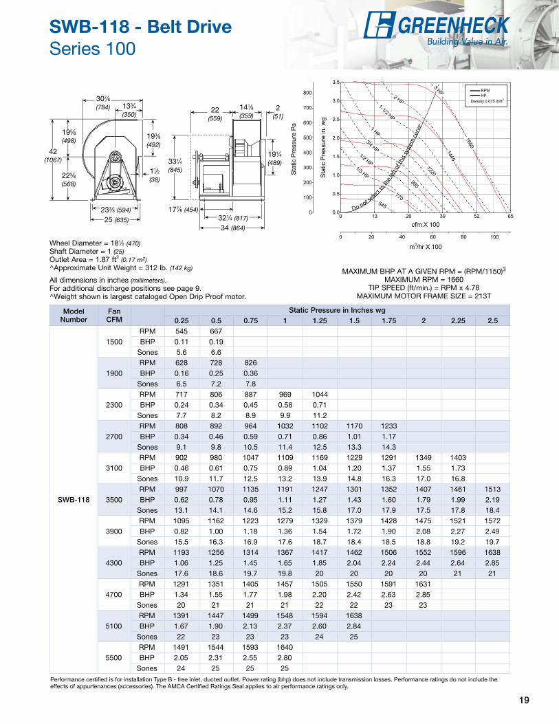
SWB-118 - Belt Drive Series 100
42 (1067)
177⁄8 (454)
25 (635)
11⁄2 (38)
195⁄8 (498)
223⁄8 (568)
193⁄8 (492)
307⁄8
(784)
331⁄4 (845)
233⁄8 (594)321⁄4 (817)
34 (864)
22 (559)
141⁄8 (359)
191⁄4 (489)
133⁄4 (350)
2 (51)
Wheel Diameter = 181⁄2 (470)Shaft Diameter = 1 (25)Outlet Area = 1.87 ft2 (0.17 m2)^Approximate Unit Weight = 312 lb. (142 kg)
All dimensions in inches (millimeters).For additional discharge positions see page 9.^Weight shown is largest cataloged Open Drip Proof motor.
Modelnumber
FanCFM
Static Pressure in Inches wg0.25 0.5 0.75 1 1.25 1.5 1.75 2 2.25 2.5
SWB‑118
1500RPM 545 667BHP 0.11 0.19
Sones 5.6 6.6
1900RPM 628 728 826BHP 0.16 0.25 0.36
Sones 6.5 7.2 7.8
2300RPM 717 806 887 969 1044BHP 0.24 0.34 0.45 0.58 0.71
Sones 7.7 8.2 8.9 9.9 11.2
2700RPM 808 892 964 1032 1102 1170 1233BHP 0.34 0.46 0.59 0.71 0.86 1.01 1.17
Sones 9.1 9.8 10.5 11.4 12.5 13.3 14.3
3100RPM 902 980 1047 1109 1169 1229 1291 1349 1403BHP 0.46 0.61 0.75 0.89 1.04 1.20 1.37 1.55 1.73
Sones 10.9 11.7 12.5 13.2 13.9 14.8 16.3 17.0 16.8
3500RPM 997 1070 1135 1191 1247 1301 1352 1407 1461 1513BHP 0.62 0.78 0.95 1.11 1.27 1.43 1.60 1.79 1.99 2.19
Sones 13.1 14.1 14.6 15.2 15.8 17.0 17.9 17.5 17.8 18.4
3900RPM 1095 1162 1223 1279 1329 1379 1428 1475 1521 1572BHP 0.82 1.00 1.18 1.36 1.54 1.72 1.90 2.08 2.27 2.49
Sones 15.5 16.3 16.9 17.6 18.7 18.4 18.5 18.8 19.2 19.7
4300RPM 1193 1256 1314 1367 1417 1462 1506 1552 1596 1638BHP 1.06 1.25 1.45 1.65 1.85 2.04 2.24 2.44 2.64 2.85
Sones 17.6 18.6 19.7 19.8 20 20 20 20 21 21
4700RPM 1291 1351 1405 1457 1505 1550 1591 1631BHP 1.34 1.55 1.77 1.98 2.20 2.42 2.63 2.85
Sones 20 21 21 21 22 22 23 23
5100RPM 1391 1447 1499 1548 1594 1638BHP 1.67 1.90 2.13 2.37 2.60 2.84
Sones 22 23 23 23 24 25
5500RPM 1491 1544 1593 1640BHP 2.05 2.31 2.55 2.80
Sones 24 25 25 25
MAXIMUM BHP AT A GIVEN RPM = (RPM/1150)3
MAXIMUM RPM = 1660TIP SPEED (ft/min.) = RPM x 4.78
MAXIMUM MOTOR FRAME SIZE = 213T
Do not select t
o the
left
of th
is sy
stem
cur
ve

20
Performance certified is for installation Type B - free inlet, ducted outlet. Power rating (bhp) does not include transmission losses. Performance ratings do not include the effects of appurtenances (accessories). The AMCA Certified Ratings Seal applies to air performance ratings only.
SWB-120 - Belt Drive Series 100
46 (1168)
193⁄8 (492)
273⁄8 (695)
11⁄2 (38)
211⁄2 (546)
241⁄2 (622)
211⁄8 (537)
335⁄8
(854)
361⁄8 (918)
255⁄8 (651)35 (889)
37 (940)
233⁄4 (603)
153⁄8 (391)
211⁄8 (537)
147⁄8 (378)
2 (51)
Wheel Diameter = 213⁄8 (543)Shaft Diameter = 1 (25)Outlet Area = 2.23 ft2 (0.21 m2)^Approximate Unit Weight = 374 lb. (170 kg)
All dimensions in inches (millimeters).For additional discharge positions see page 9.^Weight shown is largest cataloged Open Drip Proof motor.
Modelnumber
FanCFM 0.25 0.5 0.75 1 1.25 1.5 1.75 2 2.25 2.5
SWB‑120
1800RPM 471 591BHP 0.12 0.22
Sones 6.5 6.5
2250RPM 528 633 728 811BHP 0.17 0.29 0.42 0.56
Sones 6.6 6.7 8.0 9.4
2700RPM 593 686 770 850 923 989BHP 0.25 0.38 0.52 0.68 0.84 1.01
Sones 7.1 7.3 8.1 9.5 11.2 12.3
3150RPM 658 743 820 892 962 1028 1088 1145BHP 0.34 0.49 0.64 0.81 0.99 1.18 1.37 1.57
Sones 7.9 8.3 9.1 10.2 11.2 12.4 13.5 14.6
3600RPM 723 807 877 943 1006 1068 1128 1184 1237 1287BHP 0.45 0.62 0.79 0.98 1.17 1.37 1.58 1.80 2.02 2.24
Sones 9.0 10.0 10.9 11.6 12.4 13.0 13.7 14.9 16.4 18.0
4050RPM 791 873 937 999 1057 1113 1169 1223 1276 1326BHP 0.59 0.79 0.97 1.17 1.38 1.59 1.82 2.05 2.29 2.53
Sones 10.7 12.3 13.0 13.4 14.3 15.0 15.1 15.5 16.6 18.2
4500RPM 861 937 1001 1057 1113 1166 1217 1267 1316BHP 0.75 0.98 1.19 1.40 1.62 1.85 2.09 2.33 2.58
Sones 13.1 14.4 15.1 15.3 16.2 16.5 16.4 16.7 17.8
4950RPM 931 1002 1067 1121 1171 1222 1270 1316BHP 0.94 1.20 1.45 1.67 1.90 2.15 2.40 2.65
Sones 15.9 15.9 16.8 17.4 17.2 17.0 17.2 18.1
5400RPM 1003 1069 1132 1186 1234 1280 1327BHP 1.16 1.45 1.73 1.98 2.23 2.48 2.75
Sones 17.6 17.8 18.5 18.5 18.1 18.0 18.7
5850RPM 1076 1137 1196 1252 1298 1342BHP 1.42 1.74 2.04 2.34 2.60 2.87
Sones 19.3 19.8 19.3 19.3 19.7 20
6300RPM 1151 1207 1262 1316BHP 1.73 2.06 2.40 2.71
Sones 21 21 20 21
MAXIMUM BHP AT A GIVEN RPM = (RPM/943)3
MAXIMUM RPM = 1357TIP SPEED (ft/min.) = RPM x 5.23
MAXIMUM MOTOR FRAME SIZE = 215T
Do not sel
ect t
o th
e le
ft o
f thi
s sy
stem
cur
ve

21
Performance certified is for installation Type B - free inlet, ducted outlet. Power rating (bhp) does not include transmission losses. Performance ratings do not include the effects of appurtenances (accessories). The AMCA Certified Ratings Seal applies to air performance ratings only.
SWB-124 - Belt Drive Series 100
573⁄4 (1467)
193⁄4 (502)335⁄8 (854)
11⁄2 (38)
261⁄4 (667)
311⁄2 (800)
26 (661)
405⁄8 (1032)
453⁄4 (1162)
311⁄8 (791)36 (914)
411⁄2 (1054)
25 (635)
19 (483)
257⁄8 (657)
173⁄4
(451)21⁄2 (64)
Wheel Diameter = 241⁄2 (622)Shaft Diameter = 1 (25)Outlet Area = 3.40 ft2 (0.32 m2)^Approximate Unit Weight = 546 lb. (248 kg)
All dimensions in inches (millimeters).For additional discharge positions see page 9.^Weight shown is largest cataloged Open Drip Proof motor.
Do not select
to th
e le
ft of
this
syst
em c
urve
Model number
Fan CFM
Static Pressure in Inches wg0.25 0.5 0.75 1 1.25 1.5 1.75 2 2.25 2.5
SWB‑124
2800RPM 413BHP 0.19
Sones 4.9
3400RPM 464 541BHP 0.27 0.43
Sones 6.0 6.9
4000RPM 517 588 651BHP 0.38 0.56 0.74
Sones 7.5 8.3 9.2
4600RPM 572 638 696 751BHP 0.51 0.71 0.92 1.14
Sones 9.1 9.8 10.7 11.8
5200RPM 629 691 744 795 843BHP 0.66 0.91 1.13 1.37 1.62
Sones 11.0 11.6 12.7 14.0 14.4
5800RPM 687 745 795 843 888 930BHP 0.86 1.13 1.39 1.64 1.91 2.18
Sones 12.9 13.8 15.5 15.6 15.3 15.7
6400RPM 746 800 849 893 935 976 1014 1055BHP 1.09 1.38 1.68 1.96 2.24 2.54 2.83 3.15
Sones 14.7 16.4 16.8 17.2 17.3 17.6 18.0 18.5
7000RPM 806 856 903 945 984 1024 1061 1097 1132 1170BHP 1.37 1.68 2.01 2.32 2.63 2.94 3.26 3.59 3.92 4.26
Sones 16.5 17.6 18.2 19.2 19.8 19.9 20 20 21 21
7600RPM 867 913 958 999 1037 1073 1109 1144 1177 1209BHP 1.69 2.03 2.38 2.74 3.07 3.40 3.74 4.09 4.44 4.79
Sones 18.0 19.0 19.9 21 22 22 22 23 23 23
8200RPM 927 971 1013 1053 1090 1125 1158 1192 1224BHP 2.07 2.43 2.80 3.19 3.56 3.92 4.28 4.64 5.02
Sones 20 21 22 23 24 25 25 25 25
8800RPM 989 1030 1070 1108 1144 1178 1210BHP 2.50 2.88 3.27 3.69 4.11 4.49 4.87
Sones 23 23 24 24 25 26 26
MAXIMUM BHP AT A GIVEN RPM = (RPM/713)3
MAXIMUM RPM = 1225TIP SPEED (ft/min.) = RPM x 6.41
MAXIMUM MOTOR FRAME SIZE = 256T

22
Performance certified is for installation Type B - free inlet, ducted outlet. Power rating (bhp) does not include transmission losses. Performance ratings do not include the effects of appurtenances (accessories). The AMCA Certified Ratings Seal applies to air performance ratings only.
SWB-206 - Belt Drive Series 200
265⁄8 (676)
12 (305)
167⁄8 (429)
11⁄2 (38)
111⁄2 (292)
151⁄8 (384)
111⁄4 (286)
183⁄4 (476)
221⁄4 (565)
16 (406)203⁄8 (518)
22 (559)
151⁄2 (394)
81⁄4 (210)
11 (279)
85⁄8 (219)
2 (51)
Wheel Diameter = 111⁄8 (283)Shaft Diameter = 3/4 (19)Outlet Area = 0.63 ft2 (0.06 m2)^Approximate Unit Weight = 140 lb. (64 kg)
All dimensions in inches (millimeters).For additional discharge positions see page 9.^Weight shown is largest cataloged Open Drip Proof motor.
Modelnumber
FanCFM
Static Pressure in Inches wg0.5 1 1.5 1.75 2 2.5 2.75 3 3.5 3.75
SWB‑206
70RPM 1201BHP 0.03
Sones 6.4
120RPM 1262 1722 2079 2238BHP 0.04 0.09 0.16 0.20
Sones 6.8 9.2 11.9 13.2
170RPM 1350 1786 2137 2292 2435 2698 2822 2941 3165 3272BHP 0.05 0.11 0.19 0.23 0.27 0.35 0.40 0.45 0.56 0.62
Sones 7.4 9.8 12.5 13.8 15.0 17.8 19.1 20 22 24
220RPM 1489 1868 2203 2355 2497 2760 2881 2997 3216 3319BHP 0.07 0.13 0.22 0.26 0.31 0.40 0.45 0.51 0.61 0.67
Sones 8.0 10.7 13.3 14.5 15.8 18.6 19.7 21 23 24
270RPM 1693 1975 2289 2429 2566 2825 2945 3059 3277BHP 0.10 0.16 0.25 0.29 0.35 0.45 0.51 0.57 0.68
Sones 9.0 11.8 14.2 15.3 16.7 19.4 20 22 24
320RPM 1921 2138 2395 2529 2659 2898 3014 3128 3343BHP 0.14 0.20 0.28 0.33 0.39 0.50 0.56 0.62 0.75
Sones 10.5 12.9 15.2 16.5 17.8 20 21 22 25
370RPM 2169 2341 2540 2643 2767 2998 3108 3213BHP 0.19 0.26 0.34 0.39 0.44 0.55 0.62 0.68
Sones 12.1 14.2 16.4 17.6 19.0 21 22 23
420RPM 2422 2567 2721 2817 2907 3108 3213 3313BHP 0.26 0.33 0.41 0.46 0.51 0.62 0.68 0.74
Sones 13.7 15.8 18.1 19.2 20 22 23 24
470RPM 2678 2802 2943 3010 3087 3252 3330BHP 0.35 0.42 0.51 0.55 0.60 0.71 0.77
Sones 15.8 17.7 19.7 21 22 24 24
520RPM 2936 3051 3170 3234 3296BHP 0.45 0.53 0.62 0.67 0.72
Sones 18.5 19.3 21 22 23
570RPM 3196 3303BHP 0.58 0.67
Sones 22 21
MAXIMUM BHP AT A GIVEN RPM = (RPM/3629)3
MAXIMUM RPM = 3370TIP SPEED (ft/min.) = RPM x 2.91
MAXIMUM MOTOR FRAME SIZE = 145T
Do
not s
elec
t to
the
left
of t
his
sys
tem
cur
ve

23
Performance certified is for installation Type B - free inlet, ducted outlet. Power rating (bhp) does not include transmission losses. Performance ratings do not include the effects of appurtenances (accessories). The AMCA Certified Ratings Seal applies to air performance ratings only.
SWB-207 - Belt Drive Series 200
Wheel Diameter = 111⁄8 (283)Shaft Diameter = 3/4 (19)Outlet Area = 0.63 ft2 (0.06 m2)^Approximate Unit Weight = 140 lb. (64 kg)
All dimensions in inches (millimeters).For additional discharge positions see page 9.^Weight shown is largest cataloged Open Drip Proof motor.
Modelnumber
FanCFM
Static Pressure in Inches wg0.5 1 1.5 2 2.5 3 3.5 4 4.5 5
SWB‑207
200RPM 1098 1458BHP 0.04 0.10
Sones 6.2 9.1
280RPM 1244 1549 1808 2060BHP 0.06 0.12 0.19 0.27
Sones 7.3 9.7 11.1 13.3
360RPM 1415 1687 1923 2139 2333 2534BHP 0.09 0.16 0.23 0.32 0.40 0.51
Sones 8.5 10.7 12.1 14.1 15.7 17.7
440RPM 1591 1855 2064 2259 2446 2618 2777 2941 3103 3255BHP 0.13 0.21 0.29 0.38 0.48 0.58 0.68 0.80 0.94 1.07
Sones 10.0 12.4 14.2 15.5 17.4 19.1 21 22 24 25
520RPM 1793 2023 2230 2406 2577 2735 2893 3040 3179 3311BHP 0.19 0.28 0.37 0.47 0.57 0.68 0.79 0.91 1.03 1.16
Sones 12.6 15.0 16.5 17.9 19.5 21 23 24 25 26
600RPM 2007 2195 2404 2574 2725 2878 3021 3158 3295BHP 0.26 0.35 0.47 0.57 0.68 0.80 0.92 1.04 1.17
Sones 16.0 17.1 18.9 21 22 24 25 26 27
680RPM 2226 2395 2565 2751 2898 3034 3168 3300BHP 0.36 0.45 0.57 0.70 0.81 0.93 1.06 1.20
Sones 18.4 19.5 21 23 25 25 26 28
760RPM 2449 2600 2751 2911 3075 3208 3332BHP 0.47 0.58 0.69 0.83 0.97 1.11 1.24
Sones 22 23 24 26 27 28 29
840RPM 2678 2815 2951 3084 3235BHP 0.61 0.73 0.85 0.98 1.13
Sones 25 27 27 28 29
920RPM 2909 3034 3156 3282BHP 0.78 0.90 1.03 1.17
Sones 28 29 30 31
1000RPM 3142 3255BHP 0.97 1.11
Sones 30 32
265⁄8 (676)
12 (305)
167⁄8 (429)
11⁄2 (38)
111⁄2 (292)
151⁄8
(384)
111⁄4 (286)
183⁄4 (476)
221⁄4 (565)
16 (406)
203⁄8 (518)
22 (559)
151⁄2 (394)
81⁄4 (210)
11 (279)
85⁄8
(219)2
(51)
MAXIMUM BHP AT A GIVEN RPM = (RPM/3099)3
MAXIMUM RPM = 3370TIP SPEED (ft/min.) = RPM x 2.91
MAXIMUM MOTOR FRAME SIZE = 145T
Do not
sele
ct to
the
left
of t
his
syst
em c
urve

24
Performance certified is for installation Type B - free inlet, ducted outlet. Power rating (bhp) does not include transmission losses. Performance ratings do not include the effects of appurtenances (accessories). The AMCA Certified Ratings Seal applies to air performance ratings only.
SWB-208 - Belt Drive Series 200
Wheel Diameter = 111⁄8 (283)Shaft Diameter = 3/4 (19)Outlet Area = 0.63 ft2 (0.06 m2)^Approximate Unit Weight = 140 lb. (64 kg)
All dimensions in inches (millimeters).For additional discharge positions see page 9.^Weight shown is largest cataloged Open Drip Proof motor.
Modelnumber
FanCFM
Static Pressure in Inches wg0.5 0.75 1 1.5 2 2.5 3 3.5 4 4.5
SWB‑208
250RPM 1125 1343BHP 0.04 0.06
Sones 7.0 8.0
370RPM 1270 1451 1610 1909 2172BHP 0.06 0.09 0.11 0.18 0.26
Sones 7.7 8.3 8.8 10.9 13.2
490RPM 1445 1606 1753 2014 2240 2472 2681 2874BHP 0.09 0.12 0.16 0.23 0.30 0.39 0.49 0.59
Sones 8.6 9.1 9.7 11.4 13.1 15.3 17.6 19.9
610RPM 1640 1785 1918 2160 2378 2575 2755 2941 3121 3289BHP 0.12 0.16 0.21 0.29 0.38 0.47 0.56 0.67 0.79 0.91
Sones 9.2 10.5 11.3 12.5 14.4 16.2 18.1 21 22 23
730RPM 1852 1980 2101 2323 2528 2715 2892 3056 3210 3357BHP 0.18 0.22 0.27 0.37 0.47 0.57 0.68 0.79 0.90 1.01
Sones 11.2 12.4 12.9 13.8 14.8 17.8 19.9 22 22 23
850RPM 2076 2189 2298 2505 2693 2871 3039 3196 3348BHP 0.24 0.29 0.34 0.45 0.57 0.69 0.81 0.93 1.06
Sones 13.5 14.1 14.6 15.6 16.5 17.6 18.6 22 23
970RPM 2310 2409 2507 2697 2874 3041 3198 3350BHP 0.33 0.38 0.44 0.56 0.69 0.82 0.95 1.09
Sones 15.3 16.0 16.6 17.7 18.6 19.5 20 21
1090RPM 2548 2637 2725 2896 3065 3222BHP 0.44 0.50 0.56 0.69 0.82 0.97
Sones 17.5 18.1 18.8 20 21 21
1210RPM 2790 2872 2951 3110 3263BHP 0.57 0.63 0.70 0.84 0.98
Sones 19.9 21 21 22 23
1330RPM 3035 3111 3184 3329BHP 0.73 0.80 0.87 1.02
Sones 22 23 24 25
1450RPM 3282 3352BHP 0.91 0.99
Sones 26 25
265⁄8
(676)
12 (305)
167⁄8 (429)
11⁄2 (38)
111⁄2
(292)
151⁄8 (384)
111⁄4 (286)
183⁄4 (476)
221⁄4
(565)
16 (406)203⁄8 (518)
22 (559)
151⁄2
(394)
81⁄4 (210)
11 (279)
85⁄8 (219)
2 (51)
MAXIMUM BHP AT A GIVEN RPM = (RPM/3242)3
MAXIMUM RPM = 3370TIP SPEED (ft/min.) = RPM x 2.91
MAXIMUM MOTOR FRAME SIZE = 145T
0 500 1000 1500 2000 2500
0
200
400
600
800
1000
1200
0 200 400 600 800 1000 1200 1400 16000.0
0.5
1.0
1.5
2.0
2.5
3.0
3.5
4.0
4.5
5.0
5.5
Sta
tic
Pre
ssur
e in
. wg
cfm
m3/hr
Sta
tic
Pre
ssur
e P
a
Do not
sel
ect t
o th
e le
ft o
f thi
s sy
stem
cur
ve
RPM HP
Density 0.075 lb/ft³
1 1/2 HP 3/4 HP
1/2 HP
1/3 HP 1/4 HP
1 HP
3370
2830
2290
1750 1210 670

25
Performance certified is for installation Type B - free inlet, ducted outlet. Power rating (bhp) does not include transmission losses. Performance ratings do not include the effects of appurtenances (accessories). The AMCA Certified Ratings Seal applies to air performance ratings only.
SWB-210 - Belt Drive Series 200
Wheel Diameter = 111⁄8 (283)Shaft Diameter = 3/4 (19)Outlet Area = 0.63 ft2 (0.06 m2)^Approximate Unit Weight = 140 lb. (64 kg)
All dimensions in inches (millimeters).For additional discharge positions see page 9.^Weight shown is largest cataloged Open Drip Proof motor.
Modelnumber
FanCFM
Static Pressure in Inches wg0.5 1 1.5 2 2.5 3 3.5 4 4.5 5
SWB‑210
625RPM 1158 1501 1809BHP 0.08 0.17 0.27
Sones 6.3 7.6 9.4
800RPM 1311 1583 1846 2106 2334BHP 0.12 0.21 0.31 0.44 0.58
Sones 7.4 8.2 9.8 11.9 13.9
975RPM 1480 1714 1936 2143 2371 2578 2768BHP 0.17 0.27 0.38 0.50 0.65 0.81 0.97
Sones 8.6 9.5 10.7 12.4 14.3 15.4 16.6
1150RPM 1661 1872 2063 2250 2431 2615 2805 2982 3148 3305BHP 0.24 0.35 0.47 0.60 0.74 0.90 1.07 1.26 1.45 1.65
Sones 10.0 11.0 12.3 13.9 14.8 15.8 17.1 18.3 19.5 21
1325RPM 1853 2041 2214 2379 2541 2704 2854 3019 3185 3342BHP 0.32 0.45 0.58 0.72 0.87 1.03 1.19 1.38 1.58 1.79
Sones 11.9 12.9 14.3 15.2 15.9 16.7 17.6 18.8 20 21
1500RPM 2054 2214 2381 2528 2676 2815 2964 3103 3235BHP 0.43 0.57 0.72 0.87 1.03 1.20 1.37 1.55 1.73
Sones 14.0 15.1 16.0 16.6 17.3 18.1 18.8 19.6 21
1675RPM 2258 2402 2550 2694 2825 2958 3082 3214 3344BHP 0.56 0.71 0.88 1.05 1.21 1.39 1.58 1.77 1.96
Sones 16.5 17.0 17.6 18.3 19.0 19.7 20 21 22
1850RPM 2465 2594 2724 2863 2990 3108 3229 3345BHP 0.72 0.89 1.06 1.25 1.43 1.61 1.81 2.01
Sones 18.3 18.7 19.3 20 21 21 22 23
2025RPM 2674 2793 2913 3034 3159 3274BHP 0.91 1.09 1.28 1.47 1.68 1.88
Sones 20 21 21 22 23 23
2200RPM 2885 2996 3104 3214 3329BHP 1.13 1.33 1.53 1.73 1.95
Sones 22 23 24 24 25
2375RPM 3096 3201 3300BHP 1.39 1.60 1.82
Sones 25 25 26
265⁄8
(676)
12 (305)
167⁄8 (429)
11⁄2 (38)
111⁄2
(292)
151⁄8
(384)
111⁄4
(286)
183⁄4 (476)
221⁄4 (565)
16 (406)
203⁄8 (518)
22 (559)
151⁄2 (394)
81⁄4 (210)
11 (279)
85⁄8 (219)
2 (51)
MAXIMUM BHP AT A GIVEN RPM = (RPM/2649)3
MAXIMUM RPM = 3370TIP SPEED (ft/min.) = RPM x 2.91
MAXIMUM MOTOR FRAME SIZE = 145T
Do not select
to th
e le
ft of
this
syst
em c
urve

26
Performance certified is for installation Type B - free inlet, ducted outlet. Power rating (bhp) does not include transmission losses. Performance ratings do not include the effects of appurtenances (accessories). The AMCA Certified Ratings Seal applies to air performance ratings only.
SWB-212 - Belt Drive Series 200
283⁄8 (721)
12 (305)
167⁄8 (429)
11⁄2 (38)
131⁄4 (337)
151⁄8 (384)
13 (330)
213⁄8 (543)
221⁄4 (565)
16 (406)213⁄8 (543)
229⁄10 (582)
151⁄2
(394)
95⁄8 (244)
13 (330)
93⁄4 (248)
2 (51)
Wheel Diameter = 121⁄4 (311)Shaft Diameter = 1 (25)Outlet Area = 0.85 ft2 (0.08 m2)^Approximate Unit Weight = 170 lb. (77 kg)
All dimensions in inches (millimeters).For additional discharge positions see page 9.^Weight shown is largest cataloged Open Drip Proof motor.
Modelnumber
FanCFM
Static Pressure in Inches wg0.5 1 1.5 2 2.5 3 3.5 4 4.5 5
SWB‑212
600RPM 1022 1372BHP 0.08 0.16
Sones 6.0 7.9
850RPM 1150 1447 1710 1941BHP 0.11 0.21 0.33 0.45
Sones 7.2 8.5 10.4 12.7
1100RPM 1325 1561 1799 2005 2208 2392 2562 2719BHP 0.17 0.28 0.42 0.56 0.71 0.87 1.03 1.20
Sones 8.7 9.8 11.4 13.6 15.2 16.5 17.8 19.0
1350RPM 1522 1728 1913 2113 2291 2457 2625 2783 2931 3071BHP 0.25 0.38 0.52 0.68 0.85 1.03 1.21 1.40 1.59 1.79
Sones 10.5 11.7 13.2 14.9 16.0 17.2 18.5 19.8 21 23
1600RPM 1732 1905 2080 2233 2404 2564 2712 2851 2995 3135BHP 0.36 0.51 0.67 0.84 1.02 1.21 1.41 1.62 1.83 2.05
Sones 12.8 14.0 15.7 16.5 17.4 18.4 19.5 21 22 23
1850RPM 1947 2104 2255 2403 2538 2679 2825 2962 3091BHP 0.50 0.66 0.84 1.03 1.22 1.43 1.65 1.87 2.10
Sones 15.6 16.8 17.6 18.4 19.2 20 21 22 23
2100RPM 2177 2312 2443 2578 2708 2830 2944 3076BHP 0.69 0.86 1.05 1.26 1.47 1.69 1.91 2.16
Sones 18.4 19.0 19.7 21 21 22 23 24
2350RPM 2409 2524 2646 2761 2883 3001 3112BHP 0.92 1.10 1.31 1.53 1.76 2.00 2.24
Sones 21 21 22 23 24 25 26
2600RPM 2641 2739 2855 2962 3065BHP 1.20 1.39 1.62 1.85 2.10
Sones 23 24 25 26 27
2850RPM 2874 2968 3067 3169BHP 1.53 1.75 1.98 2.23
Sones 27 27 28 29
3100RPM 3108 3199BHP 1.91 2.17
Sones 30 31
MAXIMUM BHP AT A GIVEN RPM = (RPM/2372)3
MAXIMUM RPM = 3262TIP SPEED (ft/min.) = RPM x 3.21
MAXIMUM MOTOR FRAME SIZE = 145T
Do not s
elec
t to
the
left
of t
his
syst
em c
urve

27
Performance certified is for installation Type B - free inlet, ducted outlet. Power rating (bhp) does not include transmission losses. Performance ratings do not include the effects of appurtenances (accessories). The AMCA Certified Ratings Seal applies to air performance ratings only.
SWB-213 - Belt Drive Series 200
311⁄4 (794)
13 (330)
187⁄8 (479)
11⁄2 (38)
145⁄8 (371)
165⁄8 (422)
141⁄4 (362)
233⁄8 (594)
243⁄4 (629)
175⁄8 (448)221⁄2 (572)
251⁄8 (638)
163⁄4
(425)
105⁄8 (270)
14 (356)
105⁄8 (270)
2 (51)
Wheel Diameter = 131⁄2 (343)Shaft Diameter = 1 (25)Outlet Area = 1.03 ft2 (0.10 m2)^Approximate Unit Weight = 183 lb. (83 kg)
All dimensions in inches (millimeters).For additional discharge positions see page 9.^Weight shown is largest cataloged Open Drip Proof motor.
Modelnumber
FanCFM
Static Pressure in Inches wg0.5 0.75 1 1.5 2 2.5 3 3.5 4 4.5
SWB‑213
1000RPM 998 1144 1287BHP 0.12 0.18 0.24
Sones 6.9 7.5 8.4
1280RPM 1134 1248 1358 1585BHP 0.18 0.24 0.31 0.46
Sones 8.2 8.7 9.2 11.0
1560RPM 1290 1384 1478 1660 1850 2034BHP 0.26 0.33 0.40 0.56 0.74 0.95
Sones 9.6 10.2 10.8 12.2 14.2 15.8
1840RPM 1457 1540 1619 1778 1931 2093 2249BHP 0.37 0.45 0.53 0.70 0.89 1.10 1.32
Sones 11.5 12.0 12.6 14.1 15.5 16.5 17.7
2120RPM 1629 1703 1775 1913 2051 2181 2318 2462 2596 2730BHP 0.51 0.59 0.69 0.87 1.08 1.29 1.52 1.77 2.03 2.31
Sones 13.7 14.2 15.0 16.3 17.1 17.9 18.8 19.8 21 23
2400RPM 1807 1874 1938 2063 2184 2307 2423 2543 2665 2790BHP 0.68 0.78 0.88 1.09 1.30 1.53 1.78 2.03 2.29 2.58
Sones 16.4 17.0 17.3 18.1 18.8 19.7 20 21 22 24
2680RPM 1987 2048 2107 2222 2332 2440 2550 2656 2758 2869BHP 0.89 1.01 1.12 1.34 1.58 1.81 2.07 2.34 2.62 2.90
Sones 18.8 19.0 19.3 20 21 22 22 23 24 25
2960RPM 2170 2226 2280 2386 2489 2587 2685 2784 2884BHP 1.14 1.27 1.40 1.64 1.89 2.16 2.42 2.69 2.99
Sones 21 21 21 22 23 24 25 26 27
3240RPM 2355 2407 2457 2555 2650 2744 2832BHP 1.44 1.58 1.72 1.99 2.26 2.54 2.83
Sones 23 23 24 25 25 26 27
3520RPM 2541 2589 2636 2727 2816BHP 1.79 1.94 2.10 2.40 2.68
Sones 26 26 27 27 28
3800RPM 2729 2773 2817BHP 2.19 2.36 2.53
Sones 29 30 30
MAXIMUM BHP AT A GIVEN RPM = (RPM/2002)3
MAXIMUM RPM = 2902TIP SPEED (ft/min.) = RPM x 3.53
MAXIMUM MOTOR FRAME SIZE = 184T
Do not s
elect
to th
e le
ft o
f thi
s sys
tem
cur
ve

28
Performance certified is for installation Type B - free inlet, ducted outlet. Power rating (bhp) does not include transmission losses. Performance ratings do not include the effects of appurtenances (accessories). The AMCA Certified Ratings Seal applies to air performance ratings only.
SWB-215 - Belt Drive Series 200
343⁄4 (883)
15 (381)
211⁄8 (537)
11⁄2 (38)
161⁄4 (413)
181⁄2
(470)
153⁄4 (400)
253⁄4 (654)
271⁄2 (699)
20 (508)241⁄8 (613)
281⁄4 (714)
181⁄2 (470)
115⁄8 (295)
157⁄8 (403)
115⁄8 (296)
2 (51)
Wheel Diameter = 15 (381)Shaft Diameter = 1 (25)Outlet Area = 1.25 ft2 (0.12 m2)^Approximate Unit Weight = 231 lb. (105 kg)
All dimensions in inches (millimeters).For additional discharge positions see page 9.^Weight shown is largest cataloged Open Drip Proof motor.
Modelnumber
FanCFM
Static Pressure in Inches wg0.5 0.75 1 1.5 2 2.5 3 3.5 4 4.5
SWB‑215
1200RPM 886 1024 1157BHP 0.15 0.21 0.29
Sones 6.9 7.5 8.5
1550RPM 1009 1112 1214 1421BHP 0.22 0.29 0.37 0.56
Sones 8.2 8.7 9.3 11.2
1900RPM 1150 1236 1322 1487 1661 1830BHP 0.32 0.40 0.49 0.68 0.91 1.16
Sones 9.7 10.2 10.8 12.3 14.4 15.9
2250RPM 1301 1377 1449 1593 1732 1879 2020 2165BHP 0.45 0.54 0.64 0.85 1.09 1.34 1.61 1.92
Sones 11.5 12.1 12.7 14.2 15.6 16.6 17.9 19.3
2600RPM 1458 1525 1591 1715 1840 1958 2083 2213 2333 2456BHP 0.62 0.72 0.84 1.07 1.32 1.58 1.86 2.17 2.48 2.83
Sones 13.8 14.3 15.0 16.3 17.2 18.0 19.0 20 21 23
2950RPM 1620 1680 1738 1852 1961 2072 2176 2285 2396BHP 0.83 0.96 1.08 1.33 1.59 1.88 2.18 2.49 2.81
Sones 16.5 17.0 17.4 18.2 19.0 19.8 21 22 23
3300RPM 1785 1839 1893 1996 2095 2193 2293 2388BHP 1.09 1.23 1.37 1.65 1.94 2.23 2.54 2.88
Sones 19.0 19.2 19.4 20 21 22 23 24
3650RPM 1951 2001 2050 2145 2238 2326 2416BHP 1.41 1.56 1.72 2.02 2.33 2.66 2.98
Sones 21 21 22 22 23 24 25
4000RPM 2120 2166 2211 2299 2385BHP 1.78 1.95 2.13 2.46 2.79
Sones 24 24 24 25 26
4350RPM 2290 2332 2374 2456BHP 2.21 2.41 2.60 2.97
Sones 26 27 27 28
4700RPM 2460 2500BHP 2.72 2.93
Sones 30 30
MAXIMUM BHP AT A GIVEN RPM = (RPM/1679)3
MAXIMUM RPM = 2604TIP SPEED (ft/min.) = RPM x 3.93
MAXIMUM MOTOR FRAME SIZE = 184T
Do not s
elect
to th
e le
ft o
f thi
s sy
stem
cur
ve

29
Performance certified is for installation Type B - free inlet, ducted outlet. Power rating (bhp) does not include transmission losses. Performance ratings do not include the effects of appurtenances (accessories). The AMCA Certified Ratings Seal applies to air performance ratings only.
SWB-216 - Belt Drive Series 200
381⁄8 (968)
16 (406)
227⁄8 (581)
11⁄2 (38)
173⁄4 (451)
203⁄8 (518)
171⁄2 (445)
28 (711)
30 (762)
213⁄8 (543)281⁄4 (718)
303⁄8 (772)
191⁄2 (495)
123⁄4 (324)
171⁄2 (445)
121⁄2 (318)
2 (51)
Wheel Diameter = 161⁄2 (419)Shaft Diameter = 11⁄4 (32)Outlet Area = 1.52 ft2 (0.14 m2)^Approximate Unit Weight = 251 lb. (114 kg)
All dimensions in inches (millimeters).For additional discharge positions see page 9.^Weight shown is largest cataloged Open Drip Proof motor.
Modelnumber
FanCFM
Static Pressure in Inches wg0.5 0.75 1 1.5 2 2.5 3 3.5 4 4.5
SWB‑216
1200RPM 762 900BHP 0.15 0.22
Sones 5.9 6.9
1650RPM 848 959 1072 1267BHP 0.22 0.31 0.40 0.61
Sones 7.1 7.6 8.4 10.4
2100RPM 970 1059 1147 1322 1487 1632BHP 0.32 0.42 0.53 0.77 1.03 1.30
Sones 8.5 9.0 9.6 11.1 13.3 14.8
2550RPM 1109 1182 1255 1400 1543 1687 1818 1939BHP 0.46 0.58 0.70 0.96 1.25 1.56 1.88 2.21
Sones 10.1 10.6 11.2 12.7 14.4 15.6 16.8 18.1
3000RPM 1256 1320 1381 1505 1629 1749 1874 1994 2106 2211BHP 0.65 0.79 0.92 1.20 1.52 1.85 2.20 2.57 2.94 3.33
Sones 12.2 12.7 13.3 14.7 15.7 16.6 17.6 18.9 20 21
3450RPM 1410 1462 1520 1626 1734 1841 1949 2050 2162 2267BHP 0.90 1.04 1.20 1.51 1.84 2.20 2.57 2.96 3.38 3.80
Sones 14.6 15.1 15.7 16.6 17.4 18.3 19.2 20 21 22
3900RPM 1566 1616 1661 1758 1853 1950 2042 2141 2234 2324BHP 1.21 1.37 1.53 1.89 2.24 2.61 3.01 3.43 3.86 4.30
Sones 17.5 17.6 17.9 18.5 19.3 20 21 22 23 24
4350RPM 1724 1770 1813 1900 1985 2069 2156 2239 2326BHP 1.59 1.78 1.95 2.34 2.73 3.11 3.53 3.97 4.43
Sones 19.7 19.9 20 21 21 22 23 24 25
4800RPM 1884 1926 1967 2042 2124 2200 2277 2355BHP 2.05 2.25 2.45 2.85 3.29 3.72 4.14 4.60
Sones 22 22 23 23 24 25 26 27
5250RPM 2046 2084 2123 2194 2265 2338BHP 2.60 2.81 3.04 3.46 3.92 4.41
Sones 25 25 25 26 27 28
5700RPM 2208 2244 2279 2348BHP 3.25 3.47 3.71 4.19
Sones 28 29 29 30
MAXIMUM BHP AT A GIVEN RPM = (RPM/1414)3
MAXIMUM RPM = 2378TIP SPEED (ft/min.) = RPM x 4.32
MAXIMUM MOTOR FRAME SIZE = 184T
Do not sele
ct to
the
left
of t
his
syst
em c
urve

30
Performance certified is for installation Type B - free inlet, ducted outlet. Power rating (bhp) does not include transmission losses. Performance ratings do not include the effects of appurtenances (accessories). The AMCA Certified Ratings Seal applies to air performance ratings only.
SWB-218 - Belt Drive Series 200
42 (1067)
177⁄8 (454)
25 (635)
11⁄2 (38)
195⁄8 (498)
223⁄8 (568)
193⁄8 (492)
307⁄8 (784)
331⁄4 (845)
233⁄8 (594)321⁄4 (819)
34 (864)
22 (559)
141⁄8 (359)
191⁄4 (489)
133⁄4 (349)
2 (51)
Wheel Diameter = 181⁄4 (464)Shaft Diameter = 11⁄4 (32)Outlet Area = 1.87 ft2 (0.17 m2)^Approximate Unit Weight = 324 lb. (147 kg)
All dimensions in inches (millimeters).For additional discharge positions see page 9.^Weight shown is largest cataloged Open Drip Proof motor.
Modelnumber
FanCFM
Static Pressure in Inches wg0.5 1 1.5 2 2.5 3 3.5 4 4.5 5
SWB‑218
2000RPM 762 963 1136BHP 0.26 0.49 0.75
Sones 10.1 11.3 13.4
2500RPM 862 1023 1185 1330 1459BHP 0.37 0.62 0.92 1.24 1.58
Sones 10.1 11.6 13.0 15.2 17.9
3000RPM 974 1110 1245 1380 1507 1623 1730BHP 0.52 0.80 1.12 1.47 1.85 2.24 2.65
Sones 11.5 12.6 13.9 15.5 18.3 21 24
3500RPM 1092 1211 1327 1443 1557 1672 1779 1878 1971 2060BHP 0.72 1.03 1.36 1.74 2.15 2.58 3.02 3.48 3.95 4.43
Sones 13.6 14.2 15.2 16.8 19.1 22 25 27 29 31
4000RPM 1218 1322 1423 1525 1626 1727 1828 1927 2020 2108BHP 0.97 1.32 1.68 2.07 2.51 2.95 3.43 3.93 4.44 4.96
Sones 15.7 16.4 17.3 18.7 21 23 25 27 29 32
4500RPM 1346 1438 1530 1619 1709 1800 1890 1979 2069BHP 1.28 1.66 2.07 2.48 2.92 3.41 3.90 4.42 4.96
Sones 18.2 18.8 19.6 21 23 24 26 28 30
5000RPM 1475 1557 1643 1723 1804 1885 1967 2048BHP 1.66 2.08 2.52 2.97 3.43 3.91 4.45 5.00
Sones 21 21 22 24 25 26 28 29
5500RPM 1605 1683 1758 1834 1907 1981 2055BHP 2.10 2.58 3.04 3.54 4.03 4.54 5.07
Sones 24 24 25 26 27 28 30
6000RPM 1737 1810 1877 1949 2017 2084BHP 2.63 3.15 3.65 4.18 4.72 5.25
Sones 27 28 28 29 30 31
6500RPM 1869 1938 2002 2065 2131BHP 3.26 3.81 4.37 4.91 5.49
Sones 31 31 31 32 33
7000RPM 2003 2067 2128BHP 3.98 4.57 5.18
Sones 34 35 35
MAXIMUM BHP AT A GIVEN RPM = (RPM/1196)3
MAXIMUM RPM = 2147TIP SPEED (ft/min.) = RPM x 4.78
MAXIMUM MOTOR FRAME SIZE = 213T
Do not sel
ect t
o th
e le
ft o
f thi
s sy
stem
cur
ve

31
Performance certified is for installation Type B - free inlet, ducted outlet. Power rating (bhp) does not include transmission losses. Performance ratings do not include the effects of appurtenances (accessories). The AMCA Certified Ratings Seal applies to air performance ratings only.
SWB-220 - Belt Drive Series 200
46(1168)
193⁄8 (492)
273⁄8 (695)
11⁄2 (38)
211⁄2 (546)
241⁄2 (622)
211⁄8 (537)
335⁄8
(854)
361⁄8 (918)
255⁄8 (651)35 (889)
37 (940)
233⁄4 (603)
153⁄8 (390)
211⁄8 (537)
147⁄8
(378)2
(51)
Wheel Diameter = 20 (508)Shaft Diameter = 11⁄4 (32)Outlet Area = 2.23 ft2 (0.21 m2)^Approximate Unit Weight = 389 lb. (176 kg)
All dimensions in inches (millimeters).For additional discharge positions see page 9.^Weight shown is largest cataloged Open Drip Proof motor.
Modelnumber
FanCFM
Static Pressure in Inches wg0.5 1 1.5 2 2.5 3 3.5 4 4.5 4.75
SWB‑220
2000RPM 647 860BHP 0.25 0.51
Sones 8.7 11.5
2650RPM 731 897 1065 1206BHP 0.36 0.65 1.00 1.39
Sones 9.2 11.2 13.4 15.9
3300RPM 836 970 1104 1243 1367 1480BHP 0.53 0.85 1.21 1.64 2.10 2.58
Sones 10.6 12.1 13.5 15.8 19.0 22
3950RPM 951 1064 1177 1289 1405 1517 1621 1717 1807 1851BHP 0.76 1.11 1.51 1.94 2.43 2.96 3.51 4.08 4.67 4.97
Sones 13.0 13.7 14.9 16.4 19.4 23 26 28 30 32
4600RPM 1072 1171 1267 1364 1461 1556 1658 1754 1845 1888BHP 1.06 1.46 1.88 2.35 2.85 3.38 3.98 4.60 5.23 5.55
Sones 15.2 15.8 16.8 18.4 21 23 26 28 31 32
5250RPM 1198 1285 1370 1454 1539 1624 1708 1792 1882 1925BHP 1.44 1.88 2.35 2.84 3.37 3.94 4.52 5.15 5.83 6.18
Sones 17.8 18.4 19.4 21 23 25 26 28 31 32
5900RPM 1325 1401 1481 1555 1630 1706 1781 1857 1932BHP 1.90 2.40 2.92 3.45 4.00 4.58 5.23 5.87 6.52
Sones 21 21 22 24 25 26 28 30 32
6550RPM 1453 1525 1594 1664 1731 1799 1867 1935BHP 2.47 3.04 3.59 4.18 4.76 5.37 6.01 6.70
Sones 24 25 25 26 27 29 30 32
7200RPM 1583 1650 1711 1777 1840 1900BHP 3.15 3.78 4.37 5.01 5.66 6.30
Sones 28 28 28 29 30 32
7850RPM 1714 1776 1835 1892 1952BHP 3.97 4.64 5.32 5.96 6.67
Sones 31 32 32 33 34
8500RPM 1846 1904 1960BHP 4.92 5.63 6.38
Sones 36 36 37
MAXIMUM BHP AT A GIVEN RPM = (RPM/1027)3
MAXIMUM RPM = 1961TIP SPEED (ft/min.) = RPM x 5.23
MAXIMUM MOTOR FRAME SIZE = 215T
Do not sel
ect t
o th
e le
ft o
f thi
s sy
stem
cur
ve

32
Performance certified is for installation Type B - free inlet, ducted outlet. Power rating (bhp) does not include transmission losses. Performance ratings do not include the effects of appurtenances (accessories). The AMCA Certified Ratings Seal applies to air performance ratings only.
SWB-222 - Belt Drive Series 200
521⁄2
(1334)
20 (508)301⁄2 (775)
11⁄2 (38)
233⁄4 (603)
283⁄4 (730)
231⁄2 (597)
367⁄8 (937)
411⁄2 (1054)
281⁄4 (718)
341⁄8 (867)
395⁄8 (1006)
24 (610)
17 (432)
23 (584)
161⁄4
(413)21⁄2 (64)
Wheel Diameter = 221⁄4 (565)Shaft Diameter = 11⁄4 (32)Outlet Area = 2.74 ft2 (0.25 m2)^Approximate Unit Weight = 450 lb. (204 kg)
All dimensions in inches (millimeters).For additional discharge positions see page 9.^Weight shown is largest cataloged Open Drip Proof motor.
Modelnumber
FanCFM
Static Pressure in Inches wg0.5 1 1.5 2 2.5 3 3.5 4 4.5 5
SWB‑222
2500RPM 602 783 949BHP 0.30 0.59 0.93
Sones 9.3 11.5 14.3
3250RPM 677 831 971 1099 1226BHP 0.43 0.77 1.15 1.56 2.01
Sones 9.7 11.5 13.8 16.6 20
4000RPM 768 892 1019 1137 1241 1347 1452BHP 0.61 0.99 1.43 1.88 2.36 2.88 3.42
Sones 11.2 12.6 14.3 16.8 20 24 27
4750RPM 868 975 1080 1186 1289 1383 1470 1556 1648 1735BHP 0.86 1.27 1.75 2.27 2.80 3.36 3.92 4.52 5.16 5.82
Sones 13.6 14.2 15.6 17.7 21 24 27 29 32 35
5500RPM 976 1065 1158 1249 1339 1432 1518 1598 1674 1746BHP 1.18 1.64 2.14 2.70 3.30 3.91 4.54 5.18 5.84 6.51
Sones 15.8 16.5 17.5 19.5 22 25 27 30 32 35
6250RPM 1085 1164 1244 1326 1405 1487 1567 1647 1722 1793BHP 1.60 2.09 2.64 3.22 3.85 4.53 5.22 5.92 6.63 7.36
Sones 18.4 19.0 20 22 24 26 28 30 33 35
7000RPM 1197 1267 1339 1410 1484 1553 1628 1698 1771BHP 2.10 2.66 3.23 3.85 4.52 5.20 5.95 6.73 7.50
Sones 21 22 23 25 26 27 29 31 34
7750RPM 1310 1376 1439 1503 1568 1635 1698 1764BHP 2.71 3.32 3.95 4.61 5.30 6.03 6.78 7.59
Sones 25 25 26 27 28 30 31 33
8500RPM 1424 1485 1542 1601 1659 1719 1780BHP 3.43 4.12 4.80 5.47 6.22 6.98 7.78
Sones 29 29 29 30 31 32 34
9250RPM 1539 1596 1650 1703 1756BHP 4.28 5.04 5.77 6.51 7.25
Sones 32 32 33 34 35
10000RPM 1655 1708 1760BHP 5.28 6.10 6.87
Sones 36 37 37
MAXIMUM BHP AT A GIVEN RPM = (RPM/897)3
MAXIMUM RPM = 1798TIP SPEED (ft/min.) = RPM x 5.82
MAXIMUM MOTOR FRAME SIZE = 215T
Do n
ot sel
ect t
o th
e le
ft o
f thi
s sy
stem
cur
ve

33
Performance certified is for installation Type B - free inlet, ducted outlet. Power rating (bhp) does not include transmission losses. Performance ratings do not include the effects of appurtenances (accessories). The AMCA Certified Ratings Seal applies to air performance ratings only.
SWB-224 - Belt Drive Series 200
573⁄4 (1467)
193⁄4 (502)
335⁄8 (854)
11⁄2 (38)
261⁄4 (667)
311⁄2
(800)
26 (660)
405⁄8 (1032)
453⁄4 (1162)
315⁄8 (803)36 (914)
411⁄2 (1054)
25 (635)
19 (483)
257⁄8 (657)
173⁄4 (451)
21⁄2 (64)
Wheel Diameter = 241⁄2 (622)Shaft Diameter = 11⁄2 (38)Outlet Area = 3.40 ft2 (0.32 m2)^Approximate Unit Weight = 568 lb. (258 kg)
All dimensions in inches (millimeters).For additional discharge positions see page 9.^Weight shown is largest cataloged Open Drip Proof motor.
Modelnumber
FanCFM
Static Pressure in Inches wg0.5 0.75 1 1.5 2 2.5 3 3.5 4 4.5
SWB‑224
3000RPM 526 614 699BHP 0.34 0.51 0.71
Sones 7.4 9.1 12.7
3900RPM 594 659 726 861BHP 0.50 0.68 0.89 1.37
Sones 8.5 9.4 10.4 14.5
4800RPM 674 729 783 890 1001 1106BHP 0.71 0.92 1.14 1.64 2.20 2.84
Sones 10.0 11.0 11.7 13.2 16.1 18.9
5700RPM 760 809 856 945 1036 1126 1221 1309BHP 1.00 1.24 1.49 2.01 2.60 3.22 3.95 4.72
Sones 12.4 13.0 13.5 14.7 16.5 19.1 22 25
6600RPM 851 894 936 1015 1093 1171 1251 1329 1411 1487BHP 1.36 1.64 1.92 2.49 3.11 3.77 4.49 5.24 6.10 6.98
Sones 14.5 15.2 15.8 17.0 18.2 20 23 25 27 29
7500RPM 946 982 1020 1093 1162 1230 1300 1369 1438 1508BHP 1.82 2.13 2.44 3.09 3.74 4.45 5.19 5.98 6.80 7.65
Sones 17.1 17.8 18.6 19.7 21 22 24 26 27 29
8400RPM 1041 1076 1108 1175 1240 1301 1362 1423 1484BHP 2.38 2.73 3.08 3.79 4.51 5.24 6.03 6.85 7.69
Sones 20 21 22 23 24 25 25 26 28
9300RPM 1139 1170 1200 1261 1320 1378 1433 1489BHP 3.07 3.44 3.83 4.60 5.39 6.20 7.01 7.87
Sones 24 25 25 27 27 27 28 28
10200RPM 1239 1266 1294 1348 1404 1458 1510BHP 3.89 4.29 4.71 5.55 6.41 7.28 8.16
Sones 28 29 29 30 30 30 31
11100RPM 1339 1364 1390 1440 1490BHP 4.85 5.28 5.73 6.65 7.57
Sones 31 32 32 32 33
12000RPM 1440 1463 1486 1534BHP 5.98 6.43 6.90 7.89
Sones 34 35 35 36
MAXIMUM BHP AT A GIVEN RPM = (RPM/749)3
MAXIMUM RPM = 1588TIP SPEED (ft/min.) = RPM x 6.41
MAXIMUM MOTOR FRAME SIZE = 256T
Do not s
elect
to th
e le
ft o
f thi
s sy
stem
cur
ve

34
Performance certified is for installation Type B - free inlet, ducted outlet. Power rating (bhp) does not include transmission losses. Performance ratings do not include the effects of appurtenances (accessories). The AMCA Certified Ratings Seal applies to air performance ratings only.
SWB-227 - Belt Drive Series 200
611⁄8 (1553)
221⁄4 (565)375⁄8 (956)
31⁄8 (79)
281⁄8 (714)
33 (838)
283⁄8
(721)
443⁄4 (1137)
491⁄8 (1248)
351⁄8 (892)
401⁄2 (1029)
46 (1168)
27 (686)
21 (533)
281⁄2
(724)
201⁄4 (514)
21⁄2 (64)
Wheel Diameter = 267⁄8 (683)Shaft Diameter = 11⁄2 (38)Outlet Area = 4.10 ft2
(0.38 m2)^Approximate Unit Weight = 715 lb. (324 kg)
All dimensions in inches (millimeters).For additional discharge positions see page 9.^Weight shown is largest cataloged Open Drip Proof motor.
Modelnumber
FanCFM
Static Pressure in Inches wg0.5 1 1.5 2 2.5 3 3.5 4 4.5 5
SWB‑227
4000RPM 495 648 771BHP 0.47 0.93 1.45
Sones 7.4 12.0 15.6
5000RPM 556 679 797 896BHP 0.66 1.16 1.75 2.37
Sones 8.5 10.9 14.2 16.8
6000RPM 624 720 828 927 1014 1094BHP 0.92 1.45 2.09 2.79 3.52 4.28
Sones 10.3 12.1 13.8 16.7 19.4 22
7000RPM 695 782 862 958 1045 1124 1197 1265 1335BHP 1.24 1.84 2.49 3.25 4.06 4.89 5.76 6.64 7.58
Sones 12.7 13.8 15.0 17.1 20 23 26 28 30
8000RPM 772 848 921 991 1077 1156 1228 1296 1359 1420BHP 1.65 2.32 3.02 3.77 4.65 5.56 6.50 7.46 8.45 9.46
Sones 14.6 15.9 17.2 18.4 21 24 26 28 30 33
9000RPM 850 918 985 1050 1111 1187 1260 1327 1390 1450BHP 2.15 2.90 3.67 4.47 5.32 6.29 7.31 8.34 9.41 10.49
Sones 17.0 18.4 19.6 21 22 25 27 29 31 33
10000RPM 929 991 1053 1112 1169 1226 1292 1359 1422BHP 2.76 3.58 4.43 5.29 6.19 7.13 8.18 9.30 10.43
Sones 19.8 21 22 24 25 25 27 29 32
11000RPM 1010 1067 1123 1178 1232 1284 1335 1391BHP 3.49 4.39 5.31 6.25 7.20 8.18 9.22 10.32
Sones 23 24 26 27 27 28 29 30
12000RPM 1092 1145 1195 1247 1297 1346 1394BHP 4.35 5.32 6.31 7.33 8.36 9.40 10.47
Sones 27 28 29 29 30 30 31
13000RPM 1175 1223 1271 1318 1365 1411BHP 5.35 6.39 7.47 8.55 9.66 10.78
Sones 31 31 32 32 32 33
14000RPM 1259 1303 1348 1391BHP 6.52 7.61 8.77 9.93
Sones 33 34 35 35
MAXIMUM BHP AT A GIVEN RPM = (RPM/637)3
MAXIMUM RPM = 1464TIP SPEED (ft/min.) = RPM x 7.03
MAXIMUM MOTOR FRAME SIZE = 284T
Do not sel
ect t
o th
e le
ft o
f thi
s sy
stem
cur
ve

35
Performance certified is for installation Type B - free inlet, ducted outlet. Power rating (bhp) does not include transmission losses. Performance ratings do not include the effects of appurtenances (accessories). The AMCA Certified Ratings Seal applies to air performance ratings only.
SWB-230 - Belt Drive Series 200
68 (1727)
22 (559)411⁄8 (1045)
21⁄2 (64)
313⁄8 (797)
365⁄8 (930)
32 (813)
483⁄4 (1238)
533⁄4 (1365)
383⁄8 (975)
423⁄4 (1086)
481⁄4 (1226)
27 (686)
233⁄8 (594)
313⁄4 (806)
211⁄2
(546)21⁄2 (64)
Wheel Diameter = 295⁄8 (752)Shaft Diameter = 13⁄4 (44)Outlet Area = 5.03 ft2 (0.47 m2)^Approximate Unit Weight = 810 lb. (367 kg)
All dimensions in inches (millimeters).For additional discharge positions see page 9.^Weight shown is largest cataloged Open Drip Proof motor.
Modelnumber
FanCFM
Static Pressure in Inches wg0.5 1 1.5 2 2.5 3 3.5 4 4.5 5
SWB‑230
4000RPM 418BHP 0.46
Sones 7.1
5500RPM 469 588 700BHP 0.68 1.26 1.96
Sones 8.0 10.5 15.6
7000RPM 541 631 725 818BHP 1.02 1.65 2.40 3.26
Sones 9.8 11.8 13.6 16.8
8500RPM 618 697 770 845 927 1001 1069BHP 1.48 2.21 3.00 3.87 4.88 5.95 7.05
Sones 12.7 13.8 15.1 16.9 19.9 23 26
10000RPM 701 770 835 897 961 1028 1095 1159 1218 1278BHP 2.09 2.93 3.80 4.74 5.75 6.84 8.05 9.29 10.57 11.9
Sones 15.0 16.4 17.7 19.0 21 24 26 29 31 33
11500RPM 787 847 906 962 1016 1071 1127 1186 1245 1301BHP 2.88 3.83 4.81 5.82 6.88 8.02 9.20 10.50 11.88 13.30
Sones 18.1 19.4 21 22 23 25 27 29 31 34
13000RPM 875 928 981 1032 1082 1130 1178 1228 1276BHP 3.86 4.93 6.02 7.14 8.27 9.46 10.71 12.02 13.37
Sones 22 23 24 26 27 27 28 30 32
14500RPM 964 1012 1059 1107 1152 1197 1240 1283BHP 5.08 6.26 7.46 8.69 9.94 11.20 12.49 13.87
Sones 26 27 29 29 30 30 31 32
16000RPM 1055 1098 1141 1184 1227 1268BHP 6.56 7.83 9.16 10.49 11.85 13.23
Sones 31 32 32 33 33 34
17500RPM 1146 1186 1225 1263 1303BHP 8.32 9.69 11.13 12.57 14.05
Sones 35 35 36 37 37
19000RPM 1238 1274BHP 10.40 11.90
Sones 39 39
MAXIMUM BHP AT A GIVEN RPM = (RPM/534)3
MAXIMUM RPM = 1306TIP SPEED (ft/min.) = RPM x 7.75
MAXIMUM MOTOR FRAME SIZE = 284T
Do not sel
ect t
o th
e le
ft o
f thi
s sy
stem
cur
ve

36
Performance certified is for installation Type B - free inlet, ducted outlet. Power rating (bhp) does not include transmission losses. Performance ratings do not include the effects of appurtenances (accessories). The AMCA Certified Ratings Seal applies to air performance ratings only.
SWB-233 - Belt Drive Series 200
75 (1905)
231⁄2 (597)441⁄8 (1121)
31⁄2 (89)
35 (889)
40 (1016)
347⁄8 (886)
551⁄2 (1410)
591⁄8 (1502)
415⁄8 (1057)
46 (1168)
52 (1321)
29 (737)
251⁄4 (641)
347⁄8 (886)
25 (635)
21⁄2 (64)
Wheel Diameter = 33 (838)Shaft Diameter = 13⁄4 (44)Outlet Area = 6.12 ft2 (0.57 m2)^Approximate Unit Weight = 980 lb. (445 kg)
All dimensions in inches (millimeters).For additional discharge positions see page 9.^Weight shown is largest cataloged Open Drip Proof motor.
Modelnumber
FanCFM
Static Pressure in Inches wg0.5 1 1.5 2 2.5 3 3.5 4 4.5 5
SWB‑233
6000RPM 402 508BHP 0.71 1.33
Sones 7.3 10.3
7500RPM 447 540 625BHP 0.98 1.71 2.50
Sones 8.5 10.8 13.4
9000RPM 502 584 657 728 799BHP 1.35 2.17 3.07 4.01 5.04
Sones 10.4 12.3 13.8 16.0 18.7
10500RPM 559 628 700 762 822 882 944BHP 1.82 2.72 3.72 4.78 5.88 6.99 8.27
Sones 12.7 14.0 15.4 16.9 19.3 22 25
12000RPM 620 683 743 805 859 910 965 1016 1072BHP 2.42 3.42 4.49 5.65 6.86 8.11 9.36 10.64 12.12
Sones 14.7 16.1 17.5 19.0 21 23 26 28 30
13500RPM 682 739 792 848 902 951 997 1044 1092 1138BHP 3.16 4.26 5.41 6.66 7.97 9.32 10.71 12.11 13.53 14.97
Sones 17.1 18.5 19.9 21 23 25 27 28 31 33
15000RPM 744 797 848 894 945 994 1039 1082 1122BHP 4.06 5.26 6.51 7.81 9.22 10.68 12.16 13.69 15.25
Sones 20 21 23 24 26 27 28 30 32
16500RPM 809 857 904 948 990 1037 1082 1125BHP 5.14 6.43 7.79 9.19 10.63 12.19 13.79 15.42
Sones 23 25 26 27 28 29 30 31
18000RPM 874 919 961 1004 1044 1082 1126BHP 6.42 7.81 9.26 10.77 12.31 13.89 15.59
Sones 27 28 29 30 31 31 33
19500RPM 940 981 1021 1061 1099 1136BHP 7.91 9.39 10.95 12.55 14.19 15.87
Sones 31 32 32 33 34 35
21000RPM 1006 1044 1082 1119 1156BHP 9.64 11.20 12.86 14.56 16.31
Sones 34 35 36 37 37
MAXIMUM BHP AT A GIVEN RPM = (RPM/452)3
MAXIMUM RPM STEEL/ALUMINUM = 1156/975TIP SPEED (ft/min.) = RPM x 8.64
MAXIMUM MOTOR FRAME SIZE = 286T
Do not sele
ct to
the
left
of t
his
syst
em c
urve

37
Performance certified is for installation Type B - free inlet, ducted outlet. Power rating (bhp) does not include transmission losses. Performance ratings do not include the effects of appurtenances (accessories). The AMCA Certified Ratings Seal applies to air performance ratings only.
SWB-236 - Belt Drive Series 200
831⁄8 (2111)
233⁄4 (603)485⁄8 (1235)
31⁄2 (89)
385⁄8 (981)
441⁄2 (1130)
383⁄8 (984)
607⁄8 (1546)
655⁄8 (1667)
457⁄8 (1165)
46 (1168)
553⁄8 (1407)
30 (762)
281⁄4 (718)
381⁄2 (978)
271⁄4 (692) 21⁄2
(64)
Wheel Diameter = 361⁄4 (921)Shaft Diameter = 2 (51)Outlet Area = 7.52 ft2 (0.70 m2)^Approximate Unit Weight = 1170 lb. (531 kg)
All dimensions in inches (millimeters).For additional discharge positions see page 9.^Weight shown is largest cataloged Open Drip Proof motor.
Modelnumber
FanCFM
Static Pressure in Inches wg0.5 1 1.5 2 2.5 3 3.5 4 4.5 5
SWB‑236
7000RPM 361 472BHP 0.81 1.62
Sones 7.5 12.3
9000RPM 410 492 578BHP 1.17 2.02 3.06
Sones 8.7 10.9 14.6
11000RPM 463 537 603 674 746BHP 1.66 2.68 3.70 4.95 6.37
Sones 10.6 12.5 14.2 16.9 20
13000RPM 520 586 647 702 762 820 883 945BHP 2.28 3.43 4.67 5.88 7.26 8.81 10.55 12.38
Sones 13.1 14.4 15.7 17.6 20 23 27 30
15000RPM 582 639 695 747 795 843 897 947 1001 1056BHP 3.10 4.38 5.75 7.18 8.57 10.01 11.76 13.56 15.54 17.63
Sones 15.3 16.6 18.1 19.6 22 24 27 29 32 35
17000RPM 646 697 746 794 840 882 925 970 1017 1061BHP 4.15 5.57 7.03 8.62 10.23 11.80 13.40 15.15 17.14 19.17
Sones 18.0 19.4 21 22 24 26 28 30 32 35
19000RPM 711 754 801 845 888 929 969 1006 1043BHP 5.42 6.90 8.58 10.25 12.04 13.86 15.60 17.38 19.17
Sones 21 22 24 25 27 28 30 32 34
21000RPM 777 816 859 898 938 977 1015 1051BHP 6.95 8.57 10.39 12.17 14.05 16.03 18.08 20.00
Sones 25 26 28 28 29 31 32 33
23000RPM 844 880 915 956 990 1028 1063BHP 8.76 10.59 12.38 14.46 16.38 18.47 20.63
Sones 29 30 31 32 33 34 35
25000RPM 911 945 976 1013 1048BHP 10.90 12.90 14.80 16.90 19.10
Sones 33 34 34 35 36
27000RPM 978 1010 1040 1069BHP 13.40 15.50 17.60 19.70
Sones 37 38 39 40
MAXIMUM BHP AT A GIVEN RPM = (RPM/387)3
MAXIMUM RPM STEEL/ALUMINUM = 1073/960TIP SPEED (ft/min.) = RPM x 9.46
MAXIMUM MOTOR FRAME SIZE = 286T
Do not s
elec
t to
the
left
of t
his
syst
em c
urve

Page Header
Mounting Model Performance Max Psin. wg
CertificationRating Leakage
Class ProgramAMCA UL/cUL
Roof S-CUBE 850 - 30,000 cfm 2Sound
& Air
Emergency Smoke or 705 Electrical
500ºF / 4 hrs.1,000ºF / 15 min. NA Standard
Roof RBUMO 3,200 - 61,700 cfm 1Sound
& Air
Emergency Smoke, 705 Electrical or793 Snow Load
500ºF / 4 hrs.1,000ºF / 15 min. NA 5 Day
Roof TAUB L/H 4,000 - 74,000 cfm 1Sound
& Air
Emergency Smoke, 705 Electrical or793 Snow Load
500ºF / 4 hrs.1,000ºF / 15 min. NA 10 Day
Roof or Inline SWB 70 - 27,000 cfm 5 Air Emergency Smoke
or 705 Electrical500ºF / 4 hrs.
1,000ºF / 15 min. NA 5 Day
Roof or Inline BISW 50 - 200,000 cfm 14
Sound &
Air
Emergency Smoke or 705 Electrical
500ºF / 4 hrs.1,000ºF / 15 min. NA 10 Day
Inline or Roof AX 500 - 115,000 cfm 5 Air
Emergency Smoke, 705 Electrical or793 Snow Load
302ºF / 5 hrs.482ºF / 2 hrs.500ºF / 4 hrs.
572ºF / 30 min.572ºF/ 1 hr.
NA Standard
Inline or Roof QEI 2,000 - 95,000 cfm 8.5
Sound &
Air
Emergency Smoke, 705 Electrical or793 Snow Load
500ºF / 4 hrs.572° / 1 hr. NA 10 Day
Inline or Roof QEID 1,000 - 96,000 cfm 9.5
Sound &
Air
Emergency Smoke or 705 Electrical
302ºF / 5 hrs.392°F / 2 hrs.482ºF / 1 hr
500ºF / 5 hrs.572ºF / 1 hr.
NA 10 Day
Inline or Roof TCF 1,500 - 95,000 8.5 Air
Emergency Smoke, 705 Electrical or793 Snow Load
500ºF / 4 hrs.752°F / 2 hrs.
1,000ºF / 15 min.NA 10 Day
Inline or Roof TBI-FS 4,800 - 74,000 cfm 4
Sound &
Air
Emergency Smoke, 705 Electrical or793 Snow Load
750ºF / 4 hrs.1,000ºF / 15 min. NA 10 Day
Inline or Roof TBI-CA 800 - 96,000 cfm 3.25 Air 705 Electrical 300ºF / 5 hrs. NA 10 Day
Smoke SMD 2,000 - 3,000 fpm 4 Air 555S 350ºF I, II, III Next Day
Smoke HSD-401 3,000 fpm 6. — 555S 250ºF I Standard
Fire Smoke FSD 2,000 - 3,000 fpm 4 Air 555 & 555S 350ºF / 11⁄2 - 3 hrs. I, II, III Next Day
Corridor or Out of Wall
CFSD & OFSD 2,000 - 3,000 fpm 4 Air 555 & 555S 350ºF / 11⁄2 - 3 hrs. I, II, III Next Day
Multi-Blade Fire DFD 2,000 fpm 4 Air 555 11⁄2 - 3 hrs. NA Next Day
UL 555This standard governs fire dampers which are intended for use where air ducts penetrate or terminate at openings in walls or partitions, in air transfer openings in partitions, and where air ducts extend through floors as specified in the Standard for Installation of Air-Conditioning and Ventilating Systems, NFPA 90A. In a fire emergency the fire damper is designed to close and prevent the spread of fire from one side of the wall or partition to the other. Testing includes cycling, salt spray, dust loading, dynamic closure, fire endurance, and hose stream.
UL 555SThis standard governs smoke dampers which are intended to prevent the spread of smoke when HVAC systems shut down during a fire emergency and those which control the movement of smoke within a building when the HVAC system functions in a smoke control mode. Leakage rated dampers are intended for installation in accordance with NFPA 90A. Testing includes salt spray, dust loading, cycling, temperature degradation, operation while under heated airflow, and elevated temperature leakage.
UL 705Intended to assure the buyer of the safety of electrical components and connections within power ventilators and duct fans. Limited to fans connected to permanently installed wiring that meet NFPA 70 and the National Electric Code. Tests under this standard relate to extremes of current, temperature, fuses, motor windings, bearing temperatures, and water that a fan could be subject to.
UL ‑ Power Ventilators for Smoke Control Systems
Ventilators or duct fans have been
Codes & Certifications
Emergency Smoke Control Products
38

Page Header
Mounting Model Performance Max Psin. wg
CertificationRating Program
AMCA UL/cUL
Wall CW & CWB 70 - 12,500 cfm 2.25
Sound &
Air
705 Electrical762 Grease Removal
400°F UL/cUL 762 Next Day
Roof CUE & CUBE 70 - 30,000 cfm 5
Sound &
Air
705 Electrical762 Grease Removal
400°FUL/cUL 762 Next Day
Roof H-CUE & H-CUBE 70 - 14,700 cfm 5
Sound &
Air
705 Electrical762 Grease Removal
400°FUL/cUL 762 Next Day
Roof USGF 330 - 6,800 3.25Sound
& Air
705 Electrical762 Grease Removal
400°FUL/cUL 762 10 Day
Roof or Inline SWB 70 - 27,000 cfm 5 Air
Emergency Smoke, 705 Electrical or
762 Grease Removal
400°FUL/cUL 762 5 Day
Roof or Inline BISW 50 - 200,000 cfm 14
Sound &
Air
Emergency Smoke, 705 Electrical or
762 Grease Removal
400°FUL/cUL 762 10 Day
Inline QEI 2,000 - 95,000 cfm 8.5Sound
& Air
Emergency Smoke, 705 Electrical or
762 Grease Removal793 Snow Load
400°FUL/cUL 762 10 Day
Inline TCB 360 - 24,000 4.5Sound
& Air
705 Electrical762 Grease Removal
300°FUL 762 10 Day
Roof Vektor-H 270 - 24,000 cfm 3.5Sound
& Air
705 Electrical762 Grease Removal
200°FUL 762 15 Day
investigated with respect to their operation during exposure to elevated temperatures. Installed as part of a smoke control system and in accordance NFPA 92A and 92B. Requirements also include UL 705 and if applicable UL 793. Meets the IRI and SBCCI “Standard Fire Prevention Code” requirements.
UL 762UL 762 is for exhausting grease in the airstream as found in restaurant or kitchen applications. Basic testing is the same as for UL 705 and additional testing includes operating the fan in a high temperature airstream without warpage, deterioration
or damage that would cause the fan to operate unsafely plus grease flare-up tests. Greenheck products with UL 762 include most centrifugal roof upblast and centrifugal sidewall fans, utility fans and housed centrifugal fans.
UL 793Specific code applying to power ventilators that have integral dampers. Includes the ability for automatic damper operation that does not depend on electric power that may be interrupted during fire. Dampers blades must be capable of overcoming a 10 lb. / ft2 of wind, snow, or dust load.
AMCAThe AMCA certified rating program seal assures you that a product line has been tested to the appropriate AMCA standards in accordance with a legal license agreement and that the manufacturer’s catalogued certified ratings have been submitted to the AMCA staff for approval prior to publication.
Restaurant Exhaust Fans
39

Greenheck warrants this equipment to be free from defects in material and workmanship for a period
of one year from the purchase date. Any units or parts which prove defective during the warranty
period will be replaced at our option when returned to our factory, transportation prepaid. Motors are
warranted by the motor manufacturer for a period of one year. Should motors furnished by Greenheck
prove defective during this period, they should be returned to the nearest authorized motor service
station. Greenheck will not be responsible for any removal or installation costs.
As a result of our commitment to continuous improvement, Greenheck reserves the right to change
specifications without notice.
P.O. Box 410 • Schofield, WI 54476-0410 • Phone (715) 359-6171 • greenheck.com
Building Value in Air
Our Warranty
Prepared to SupportGreen Building Efforts
Greenheck delivers value to mechanical engineers by helping them solve virtually any air quality challenges their clients face with a comprehensive selection of
top quality, innovative air-related equipment. We offer extra value to contractors by providing easy-to-install, competitively priced, reliable products that arrive on time.
And building owners and occupants value the energy efficiency, low maintenance and quiet dependable operation they experience long after the construction project ends.
Specifications
Copyright © 2008 Greenheck Fan Corp.Catalog SWB Rev. 9 June 2008
Supply, exhaust and return air fans shall be of the belt driven utility fan type in AMCA Arrangement 10 with a single width, single inlet housing, in CW or CCW rotation as specified.
The housing shall be constructed of heavy gauge steel with air tight locked formed seams; galvanized steel on Series 100, painted steel on Series 200 or aluminum optional. The housing shall be field rotatable to any of the eight standard discharge positions. Housing and bearing supports shall be constructed of welded steel members to prevent vibration and to rigidly support the shaft and bearings.
The fan wheel shall be of the non‑overloading backward inclined, centrifugal fan type and constructed of heavy gauge steel for the Series 200 (except sizes 206 to 210 have aluminum) and aluminum for the Series 100.
Wheels shall be statically and dynamically balanced. The wheel cone and fan inlet cone shall be carefully
matched for maximum performance and operating efficiency.
Motors shall be heavy duty, ball bearing type matched to the fan load and furnished at the specified voltage, phase and enclosure. The fan shaft shall be ground and polished solid steel mounted in heavy duty, permanently sealed, pillow block ball bearings. Bearings shall be selected for a minimum L10 life in excess of 100,000 hours (L50 average life of 500,000 hours) at maximum cataloged operating speed. Drives shall be sized for a minimum of 150% of driven horsepower. Pulleys shall be of the fully machined cast iron type, keyed and securely attached to the wheel and motor shafts. The motor pulley shall be adjustable for final system balancing.
All fans shall bear the AMCA Certified Ratings Seal for air performance.
Utility fans shall be model SWB (with backward inclined wheels) as manufactured by Greenheck Fan Corporation in Schofield, Wisconsin.