grasp planning to maximize task coverage
TRANSCRIPT

Article
The International Journal of
Robotics Research
2015, Vol. 34(9) 1195–1210
� The Author(s) 2015
Reprints and permissions:
sagepub.co.uk/journalsPermissions.nav
DOI: 10.1177/0278364915583880
ijr.sagepub.com
Grasp planning to maximize task coverage
Yun Lin and Yu Sun
Abstract
This paper proposes a task-oriented grasp quality metric based on distribution of task disturbance, which could be used
to search for a grasp that covers the most significant part of the disturbance distribution. Rather than using a uniformly
distributed task wrench space, this paper models a manipulation task with a non-parametric statistical distribution model
built from the disturbance data captured during the task demonstrations. The grasp resulting from maximizing the pro-
posed grasp quality criterion is prone to increasing the coverage of most frequent disturbances. To reduce the computa-
tional complexity of the search in a high-dimensional robotic hand configuration space, as well as to avoid the
correspondence problem, the candidate grasps are computed from a reduced configuration space that is confined by a set
of given thumb placements and thumb directions. The proposed approach has been tested both in simulation and on a real
robotic system. In simulation, the approach was validated with a Barrett hand and a Shadow hand in several manipula-
tion tasks. Experiments on a physical robotic platform verified the consistency between the proposed grasp metric and the
success rate.
Keywords
Task-oriented grasping, task modeling, task disturbance distribution, grasp quality measure
1. Introduction
In robotics, grasping has been an active research area that
involves many important research topics. Among them, the
grasp synthesis problem has attracted significant attention.
To solve this problem, numerous approaches and algo-
rithms have been developed. A detailed review of various
approaches can be found in Sahbani et al. (2012). One
direction of the grasp synthesis research is grasp planning
that applies optimization theory to search for contact place-
ment on an object and the optimal posture of the hand,
which gives rise to the difficulty in choosing a quality cri-
terion for the optimization procedure. In the literature, the
existing grasp quality measures can be associated to either
contact locations or hand configuration. Both have been
studied thoroughly. A detailed discussion of several grasp
quality measures within the two groups was provided by
Suarez et al. (2006). In this paper, we present a novel grasp
quality measure that utilizes contact locations.
When a grasp is modeled with contact between the
object and the fingers, one considers that the contact should
provide a firm grasp under external disturbances. A widely
used quality criterion in this group is the force-closure
property that measures the capability of a grasp to with-
stand external disturbance wrenches from any direction
(Kirkpatrick et al., 1992). Related research was developed
by Ferrari and Canny (1992), Pollard (1994), Miller et al.
(2003), and Hsiao et al. (2011), who proposed grasp-
planning approaches to find force-closure grasps. The
force-closure quality measure is task-independent, in which
evenly distributed wrenches in all directions were assumed
(Bicchi and Kumar, 2000).
For many manipulation tasks, however, such as writing
and handling a screwdriver, a task-related grasp criterion
can be applied in order to choose grasps that are most
appropriate to meeting specific task requirements. A
manipulation task refers to ‘‘the process of moving or rear-
ranging objects in the environment’’ (Brock et al., 2008), so
the force and motion requirements are basic task descrip-
tions that commonly exist in every task (Lin et al., 2012).
In terms of the force requirement, the object to be manipu-
lated would interact with the environment, and the interac-
tive wrench on the object would be a disturbance to the
grasp. Therefore, a task-oriented grasp should be efficient
Department of Computer Science and Engineering, University of South
Florida, FL, USA
Corresponding author:
Yu Sun, Department of Computer Science and Engineering, University of
South Florida, 4202 E Fowler Avenue, ENB 118, Tampa, FL 33620, USA.
Email: [email protected]
at Universidade de Coimbra on September 17, 2015ijr.sagepub.comDownloaded from

in resisting the disturbance wrenches required for a task.
One typical task-oriented grasp method is to choose a suit-
able task wrench space (TWS) and then measure how well
it can be fitted into a grasp wrench space (GWS) (Borst
et al., 2004; Han et al., 2000; Haschke et al., 2005; Li and
Sastry, 1988; Pollard, 1994). Few works have considered
the task information in grasp planning due to the difficulty
of modeling a task (Borst et al., 2004; Li and Sastry, 1988;
Sahbani et al., 2012). To obtain the TWS in reality, sensors
are necessary to measure the contact regions and contact
normals in human demonstration, which remains a chal-
lenge. This is the main reason why most works empirically
approximate the TWS rather than actually measure it.
Instead of a wrench space ball used in a force-closure qual-
ity measure, Li and Sastry (1988) used a six-dimensional
wrench space ellipsoid to better approximate a task to facil-
itate the computation of the quality measure. The research
by Haschke et al. (2005) approximated the TWS as a task
polytope. Kruger and van der Stappen (2011, 2013) and
Kruger et al. (2012) developed algorithms to generate two
or three feasible contact locations given one single wrench
and wrenches in its neighborhood. However, their works
were not generalized to most of the manipulation tasks
where multiple interactive wrenches may occur.
Pollard (1994) proposed the object wrench space
(OWS), which takes the complete object geometry into con-
sideration. The OWS integrates all disturbance wrenches
that can be exerted anywhere on the object. Borst et al.
(2004) presented an algorithm to approximate the OWS by
an ellipsoid and to measure how well the OWS ellipsoid
can be fitted into a GWS. The idea of OWS takes all possi-
ble disturbances into account, which is good for unknown
tasks but is not task-specific; for a specific task, a grasp
does not need to perform the whole OWS but only the
required TWS, which should be a subset of the whole
OWS.
Another difficulty of task-oriented grasp planning is the
computational complexity of searching in a high-
dimensional hand configuration space. It is, therefore, natu-
ral to introduce human experience to constrain the search
space (Billard et al., 2008; Hueser and Zhang, 2008;
Romero et al., 2008). Aleotti and Caselli (2010) used data
gloves to map human hand to robotic hand workspace and
captured TWS in virtual reality. They also considered a
database of candidate grasps, and grasps were evaluated by
a task-related quality measure. However, the correspon-
dence problem has been a crucial issue to map between
two different configuration spaces of the human hand and
the robotic hand. Research in Pollard (2004) searched for
candidate grasps by a shape-matching algorithm and evalu-
ated the grasps by a task-oriented criterion. However, the
TWS was also modeled by experience rather than actually
measured from the demonstrated task.
This paper expands our previous work (Lin and Sun,
2013b) to address the task-oriented grasp-planning prob-
lem. The main contributions of the paper are the following:
1. The task property was measured from real human
demonstration data, other than estimated or approxi-
mated by experience. Human demonstration was car-
ried out in a virtual reality environment. The users
interacted with the environment via a haptic device
Phantom OMNI (Section 2.2) and received haptic
feedback when they controlled the virtual object to
interact with the environment. The task-related distur-
bance from the environment to the object was captured
during the task execution.
2. The task requirement is modeled based on the distri-
bution of the task disturbance (Section 2.2). Rather
than simple pick-and-place tasks that have been inves-
tigated thoroughly in the literature, we move to inter-
active tasks that are full of uncertainties. Instead of
considering only the shape of the TWS, the proposed
approach takes into account the task disturbance distri-
bution measured from human demonstration, since it
is possible that disturbance wrenches occur more fre-
quently in some areas than others. The resulting grasp
should be efficient in balancing disturbances that fre-
quently occur.
3. A novel task-oriented grasp quality metric is proposed,
called the task coverage grasp quality metric (Section
2.4). A real-life robotic hand has limited grasping
force that is usually determined by the power of its
actuators. For many interactive tasks, it is impossible
to guarantee a firm grasp that can resist all possible
disturbances, especially spikes that rarely happen. We
aim to find a grasp that best allocates the capability of
the robotic hand to cover the main disturbances of the
task, instead of the rare cases. To move on from pick-
and-place tasks, and move into interactive tasks that
are full of uncertainties, we proposed this new mea-
sure to estimate how likely it is that a grasp will be
maintained during an interactive task. To reduce the
computational complexity of the search in the high-
dimensional robotic hand configuration space, we uti-
lized our previous grasp-planning approach presented
in Lin and Sun (2014), which integrates human strat-
egy (thumb placement and direction, as well as grasp
type) into grasp planning (Section 2.6). The proposed
approach has been tested both in simulation and on a
real robotic system, as described in Section 3.
2. Grasp analysis
2.1. Grasp preliminaries
Considering a multi-fingered robotic hand grasping an
object, a grasp comprises n contact points. The contact can
be modeled by three types: point contact without friction,
hard finger, and soft finger (Murray et al., 1994). Here, we
consider only the hard finger model, that is, point contact
with friction (PCWF), which is widely used in grasp analy-
sis because it has no difficulty in generalizing the model.
1196 The International Journal of Robotics Research 34(9)
at Universidade de Coimbra on September 17, 2015ijr.sagepub.comDownloaded from

Using Coulomb’s friction model, the contact force fi 2 <3
has the following constraint:
F i = fij1
mi2(fit1
2 + fit22)\f 2
i?
� �ð1Þ
where fit1 and fit2 are two tangential force components, fi’is the normal force component, and m is the coefficient of
friction. With a given friction coefficient, the maximum
tangential force is determined by the normal force. Thus,
each contact force fi is constrained to a friction cone. The
friction has a vertex at the contact point, and the axis is
along the contact normal, with an opening angle of
2tan21m.
For the convenience of computation, the circular friction
cone is usually linearized and approximated with an m-
sided pyramid. Then, any contact force fi that is within the
constraint of the friction cone can be represented as a con-
vex combination of the m force vectors on the boundary of
the cone:
fi’Xm
j = 1
aj fij ð2Þ
where coefficient aj � 0, andPm
j = 1 aj� 1. If the bound-
ary force vector fij is assumed to be of unit magnitude along
the normal component, then the normal magnitude of the
contact force fi is bounded to be 1, that is, jjfi’jj � 1.
Each local contact force will generate a force and torque in
the object coordinate, grouped as an object wrench wi 2<6. Then, the net resultant wrench can be transformed from
the local contact forces through the grasp matrix
w = Gf ð3Þ
where f = ½f T1 , . . . , f Tn �T
is a vector concatenating all con-
tact forces, and G = [G1,., Gn] 2 <6× 3n is the grasp
matrix. GWS is defined as the set of all possible resultant
wrenches w that can be generated by all feasible contact
forces lying within the friction cone. GWS is the convex
hull of all the object wrenches. The magnitude of object
wrenches scales linearly with the contact forces that are
limited by the joint capabilities. For comparison, the upper
bound is typically set to be 1. Ferrari and Canny (1992)
defined the unit GWS by bounding unitary L1 or LN norm
of the normal contact force. Since the contact force is
under the frictional constraint, constraint on the normal
component also imposes an upper bound on the contact
force. Here, by imposing the upper bound of the L1
norm to be 1, the set of all possible resultant object
wrenches produced by the grasp is defined as unit
GWS (UGWS):
UGWS = fGf jfi 2 F i, jjfi?jj � 1g ð4Þ
An important grasp property is force closure. A grasp is
force closure if for any wrench w there exists a solution
f 2 F . In other words, a force-closure grasp is able to
equilibrate external force and moment in any direction
without violating the friction constraints. It is equivalent to
the condition that there exist strict internal forces fin, such
that Gfin = 0. Thus, if the origin of the wrench space is
included in the interior of GWS, then the grasp is force clo-
sure. Similar to the GWS, a task can also be described as
the space of disturbance wrenches from the environment
that the object must resist. Ferrari and Canny (1992) quan-
tified the force-closure property by the magnitude of distur-
bance wrench that can be compensated for by the grasp in
the worst case. If no task-oriented information is provided
to form a subset of the whole space of wrenches, a typical
TWS is a six-dimensional ball Tball centered at the wrench
space origin, where external disturbance is uniformly
weighted (left in Figure 1). The grasp quality is the recipro-
cal of the scale to enlarge the UGWS so that it contains the
whole TWS:
Qm(G)=1
km
ð5Þ
km(G)= min(k)jTball � k � UGWS ð6Þ
where km(G) is the minimum magnitude of normal contact
force in order to resist all task wrenches. The larger km is,
the greater the effort needed for a grasp to balance the task
wrench along the weakest direction. Grasp planning is to
find the maximum Q(G), the reciprocal of km(G).
2.2. Measure of task wrench
Instead of using a uniform ball, the quality measure in
equation (5) can also be used for different task require-
ments, such as a TWS approximated by a task ellipsoid or
a polytope.
Most of the existing work (Haschke et al., 2005; Li and
Sastry, 1988; Pollard, 2004) relied on experience to estimate
TWS and predict the contact disturbance. For example, to
dd
dd
d
d
Fig. 1. Grasp quality measures for (left) task ball represented by
the dashed circle, and (right) task ellipsoid represented by the
dashed ellipse; km is the linear scale factor to enlarge UGWS so
that it encloses the entire TWS.
Lin and Sun 1197
at Universidade de Coimbra on September 17, 2015ijr.sagepub.comDownloaded from

manipulate such tools as a pen, screwdriver, scoop, fork,
toothbrush, and so on, the contact disturbance is expected
to be applied to the tips of those tools. Then, the empirical
task-oriented disturbance wrench space is a friction cone
applied to the tip.
Moreover, the task is considered only by the shape of
the GWS without taking the wrench distribution into
account, where the wrenches are assumed to be uniformly
distributed in the space. However, this is rarely the case.
Compare a writing task and the manipulation of a screwdri-
ver, for example. Although both require the grasp to resist
disturbance force applied to the tip, they have different dis-
turbance distributions, as illustrated in Figure 2. For the
writing task, the main disturbance wrench is the force
pointed in the upper-left direction and the torque generated
along with the force. Hence, the GWS should be able to
apply the opposite force to resist the disturbance, which is
distributed primarily in the right area of the friction cone
shown in the figure. The main disturbance wrench of the
screwdriver is the normal force to the surface and the rota-
tional torque, which is generated by the physical constraint
from the screw head, around the principal axis of the
screwdriver. In the figure, we only show the force subspace
for comparison purposes. Also, the expected disturbance
force of the screwdriver is larger than that of the pen. As a
result, different distributions of wrenches in a TWS would
prefer different grasps.
Therefore, we propose to characterize the TWS and rep-
resent the task wrench distribution in it with a task wrench
cluster (TWC). It is not trivial to capture the task wrenches
applied on physical objects, and collect enough wrenches
to form a cluster that could represent the task wrench distri-
bution well. Therefore, we implemented a simulation envi-
ronment that has a virtual reality environment for visual
feedback and a six-dimensional haptic device Phantom
Omni for interaction control and haptic feedback. The
Phantom Omni allows users to control a virtual object in
terms of three-dimensional position and three-dimensional
orientation and provides them with three-dimensional
haptic feedback of the interaction force between the haptic
interaction point (HIP) and the virtual environment.
Although a single device cannot control a multi-link body
or soft objects, the HIP can be a representation of a rigid
body composing the majority of daily tools.
The virtual reality environment was developed based on
Chai3D (http://www.chai3d.org), an open-source C++library for computing haptic feedback, visualization, and
interactive real-time simulation. It integrates Open
Dynamic Engine (ODE) for collision detection and
dynamics simulation and OpenGL library for graphical
visualization. For each task, a user was asked to manipulate
a virtual tool using the haptic device (see Figure 3 for
example). The three-dimensional collision forces of the
tool with the environment were captured every iteration,
with a sampling rate of 100 Hz, and three-dimensional tor-
ques are computed from the collision forces. All wrenches
(forces and torques) collected during the task form a TWC
for that particular task:
TWC = fw(i) 2 <6jw(i)= wc(i)+ wn(i)g ð7Þ
where w(i) is a wrench at the ith iteration, wc(i) is the
wrench generated by the contacts between the tool and the
environment, and wn(i) is a non-contact wrench.
The non-contact wrench wn(i) is an offset wrench that
includes forces not acting on the surface of the object, such
as gravity and the inertial force. Gravity is the force acting
on the center of mass on the object along the vertical direc-
tion with zero torque. The direction of gravity relative to
the object coordinate frame changes with the motion of the
object, so the task of rotating an object is to stabilize a set
of gravities along multiple directions.
2.3. Study on disturbance distribution
In this section, the simulated disturbance distribution is ver-
ified and the distribution model is studied.
2.3.1. Verification on simulated disturbance data. Since
the proposed grasp planning relies heavily on simulated
disturbance measure, it is necessary to validate how reliable
and realistic the simulated data is. Thus, we evaluated the
Fig. 2. Disturbance distribution of two tasks. Left: a writing task
with a pen; right: a screwing task with a screwdriver.
Fig. 3. A user interface for demonstration. Left: the haptic
device, Phantom Omni; right: virtual environment.
1198 The International Journal of Robotics Research 34(9)
at Universidade de Coimbra on September 17, 2015ijr.sagepub.comDownloaded from
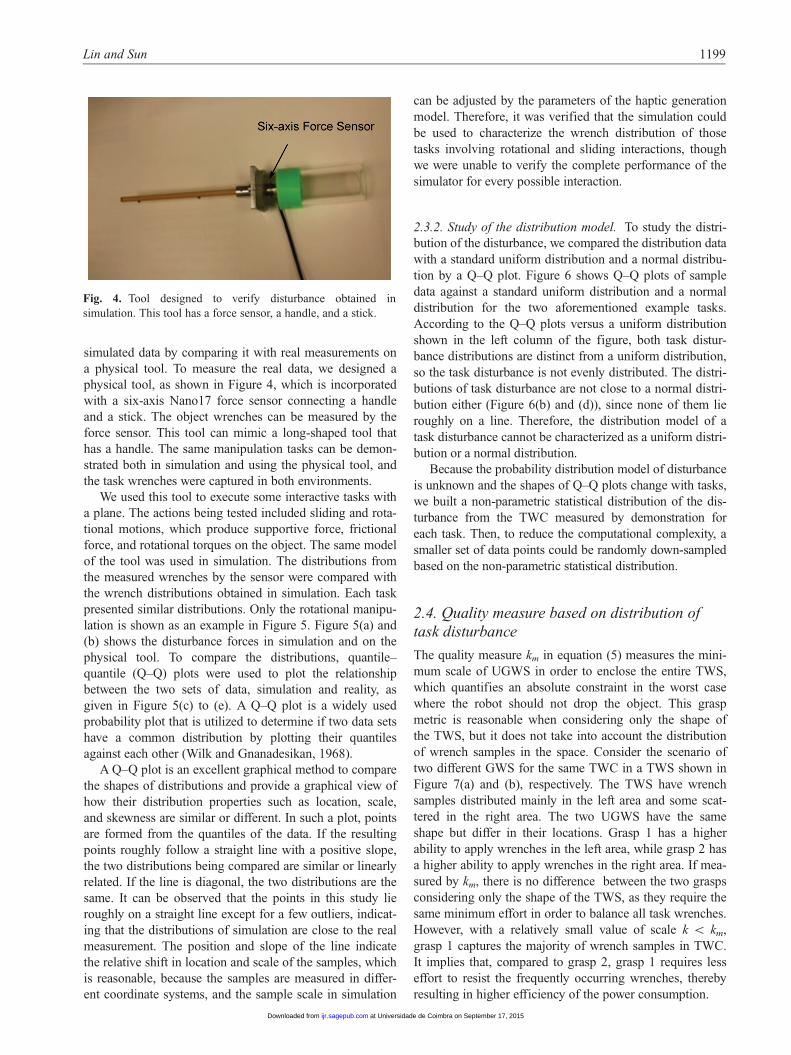
simulated data by comparing it with real measurements on
a physical tool. To measure the real data, we designed a
physical tool, as shown in Figure 4, which is incorporated
with a six-axis Nano17 force sensor connecting a handle
and a stick. The object wrenches can be measured by the
force sensor. This tool can mimic a long-shaped tool that
has a handle. The same manipulation tasks can be demon-
strated both in simulation and using the physical tool, and
the task wrenches were captured in both environments.
We used this tool to execute some interactive tasks with
a plane. The actions being tested included sliding and rota-
tional motions, which produce supportive force, frictional
force, and rotational torques on the object. The same model
of the tool was used in simulation. The distributions from
the measured wrenches by the sensor were compared with
the wrench distributions obtained in simulation. Each task
presented similar distributions. Only the rotational manipu-
lation is shown as an example in Figure 5. Figure 5(a) and
(b) shows the disturbance forces in simulation and on the
physical tool. To compare the distributions, quantile–
quantile (Q–Q) plots were used to plot the relationship
between the two sets of data, simulation and reality, as
given in Figure 5(c) to (e). A Q–Q plot is a widely used
probability plot that is utilized to determine if two data sets
have a common distribution by plotting their quantiles
against each other (Wilk and Gnanadesikan, 1968).
A Q–Q plot is an excellent graphical method to compare
the shapes of distributions and provide a graphical view of
how their distribution properties such as location, scale,
and skewness are similar or different. In such a plot, points
are formed from the quantiles of the data. If the resulting
points roughly follow a straight line with a positive slope,
the two distributions being compared are similar or linearly
related. If the line is diagonal, the two distributions are the
same. It can be observed that the points in this study lie
roughly on a straight line except for a few outliers, indicat-
ing that the distributions of simulation are close to the real
measurement. The position and slope of the line indicate
the relative shift in location and scale of the samples, which
is reasonable, because the samples are measured in differ-
ent coordinate systems, and the sample scale in simulation
can be adjusted by the parameters of the haptic generation
model. Therefore, it was verified that the simulation could
be used to characterize the wrench distribution of those
tasks involving rotational and sliding interactions, though
we were unable to verify the complete performance of the
simulator for every possible interaction.
2.3.2. Study of the distribution model. To study the distri-
bution of the disturbance, we compared the distribution data
with a standard uniform distribution and a normal distribu-
tion by a Q–Q plot. Figure 6 shows Q–Q plots of sample
data against a standard uniform distribution and a normal
distribution for the two aforementioned example tasks.
According to the Q–Q plots versus a uniform distribution
shown in the left column of the figure, both task distur-
bance distributions are distinct from a uniform distribution,
so the task disturbance is not evenly distributed. The distri-
butions of task disturbance are not close to a normal distri-
bution either (Figure 6(b) and (d)), since none of them lie
roughly on a line. Therefore, the distribution model of a
task disturbance cannot be characterized as a uniform distri-
bution or a normal distribution.
Because the probability distribution model of disturbance
is unknown and the shapes of Q–Q plots change with tasks,
we built a non-parametric statistical distribution of the dis-
turbance from the TWC measured by demonstration for
each task. Then, to reduce the computational complexity, a
smaller set of data points could be randomly down-sampled
based on the non-parametric statistical distribution.
2.4. Quality measure based on distribution of
task disturbance
The quality measure km in equation (5) measures the mini-
mum scale of UGWS in order to enclose the entire TWS,
which quantifies an absolute constraint in the worst case
where the robot should not drop the object. This grasp
metric is reasonable when considering only the shape of
the TWS, but it does not take into account the distribution
of wrench samples in the space. Consider the scenario of
two different GWS for the same TWC in a TWS shown in
Figure 7(a) and (b), respectively. The TWS have wrench
samples distributed mainly in the left area and some scat-
tered in the right area. The two UGWS have the same
shape but differ in their locations. Grasp 1 has a higher
ability to apply wrenches in the left area, while grasp 2 has
a higher ability to apply wrenches in the right area. If mea-
sured by km, there is no difference between the two grasps
considering only the shape of the TWS, as they require the
same minimum effort in order to balance all task wrenches.
However, with a relatively small value of scale k \ km,
grasp 1 captures the majority of wrench samples in TWC.
It implies that, compared to grasp 2, grasp 1 requires less
effort to resist the frequently occurring wrenches, thereby
resulting in higher efficiency of the power consumption.
Fig. 4. Tool designed to verify disturbance obtained in
simulation. This tool has a force sensor, a handle, and a stick.
Lin and Sun 1199
at Universidade de Coimbra on September 17, 2015ijr.sagepub.comDownloaded from

In cases where a robotic hand is not capable of covering
all the TWC without exceeding some force limit, it makes
more sense to capture as much of the TWC as possible.
2.4.1. The proposed grasp quality measure. Intuitively, the
grasp quality can be defined as the ratio of TWC that can
be covered by the GWS that is linearly scaling with UGWS
by a factor of k (the magnitude of normal contact force,
which is an indicator of the robotic finger capability). We
define W(G) as the subset of all wrenches in TWC, which
are within the scaled GWS for a given k:
W (G)= f8w(i) 2 TWCjw(i) 2 GWSg ð8Þ
The grasp quality can be represented as
Q(G)=jW (G)jjTWCj ð9Þ
where jW(G)j is the cardinality of the set W(G), that is, the
number of the task wrench samples covered by the GWS,
and jTWCj is the cardinality of the set TWC, that is, the
number of all wrenches in the TWC. Obviously,
0 � Q(G) � 1. The physical meaning of quality measure
Q(G) is, given a capability constraint k on the normal con-
tact forces, the percentage of task wrenches that can be
resisted by the grasp. With this new grasp quality measure,
we will be able to find an optimal grasp G that maximizes
Q(G), so it is able to apply the required task wrenches as
many as possible, without exceeding a certain amount of
contact force.
2.4.2. Selecting k. In some scenarios, the selection of k,
the scale factor to determine the size of GWS from UGWS,
will affect the selection of grasp, since as k increases, Q
increases nonlinearly. Here, we illustrate the influence of k
with two grasps in three different scenarios. Since the two
grasps may have distinct UGWS, the two UGWS would
require different scale factors, km1 and km2, to cover the
Fig. 5. Example disturbance force of manipulating a screwdriver measured in simulation, the physical tool, and robot wrist in robot
execution. (a) Disturbance force measured in simulation; (b) disturbance force measured from tool sensor; (c) to (e) Q–Q plot of
distribution of Fx, Fy and Fz in simulation against real tool measure.
Fig. 6. Q–Q plots to compare sample disturbance data with two
standard distribution models. Top row: Q–Q plots for a
screwdriver task; bottom row: Q–Q plots for manipulating a
knife; left column: Q–Q plots of sample data versus uniform
distribution; right column: Q–Q plots of sample data versus
normal distribution.
1200 The International Journal of Robotics Research 34(9)
at Universidade de Coimbra on September 17, 2015ijr.sagepub.comDownloaded from

entire TWC. In scenario 1, shown in Figure 7(c), where
km1 = km2 and for all k \ km1,m2, Q(G1) . Q(G2), select-
ing grasp 1 is always better than or equal to selecting grasp
2. In scenario 2, shown in Figure 7(d), where km2 . km1,
and for all k \ km2, Q(G1) . Q(G2), selecting grasp 1 is
always better than or equal to selecting grasp 2. However,
in scenario 3, shown in Figure 7(e), the two grasp quality
plots intersect at some random kc \ km1,m2, so
Q(G1) . Q(G2) when k \ kc, and it is the opposite when
k . kc. Then, selecting grasp 1 or grasp 2 depends on the
selection of k. Therefore, it is important to choose a mean-
ingful and reasonable k.
Since scale k stands for the amount of normal contact
force the robotic hand is expected to apply, we suggested a
scale k0 by considering both the capability of the robotic
hand and the task requirement. This paper provides an
example of k0 selection that considers both the robotic
hand capability and the features of the TWC.
In our validation experiments, we also used this k0 selec-
tion scheme as a consistent rule for comparisons. Let a(i) =
kf(i)k, which is the magnitude of f(i), the force component
in a given TWC; then, max(a(i)) represents the maximum
magnitude of all contact forces in TWC. Further, k0 is deter-
mined by the smaller value between the max(a(i)) and the
maximum force fmax that can be applied by the robotic hand,
considering the capability of robot actuators, written as
k0 = min(max(a(i)), fmax) ð10Þ
for all i = 1,.,T, where T is the number of wrench samples
in the TWC. Because the shape of the GWS does not usu-
ally fit with the shape of the TWC well, when k0 is selected
by max(a(i)), GWS does not always cover all the wrenches
in the TWC.
In this paper, we used a Barrett hand for the experiment
in a real environment. The maximum finger force of the
Barrett hand is 20 N, so we set fmax = 20 in order to bound
k0; k0 can also be set to other empirical values, for example
the amount of force that humans usually apply in a manipu-
lation. Further, k0 can also simply be the hand capability
constraint on the contact force, so a grasp will be generated
to best allocate the capability of the robotic hand to resist
most disturbances in the task. For fragile objects, k0 can be
a smaller value to impose a strict limit on normal contact
force, so that the resulting grasp will not break the object
but can still hold the object with small contact forces.
2.5. Computational efficiency of grasp quality
To compute the quality of a grasp, GWS is computed as
the convex hull of all the possible wrenches that could be
generated at all the contact points, and then all samples of
the TWS must be checked to determine if they are inside
Fig. 7. Comparison of quality measure Q in different scenarios. (a), (b): Two GWS, given the same TWS; (c) to (e): compare the plots
of Q(G1) and Q(G2) as a function of scale k in three cases. (c) Scenario 1: the quality plots of the two grasps intersect at km1 = km2, so
for all k \ km, Q(G1) . Q(G2). Thus, if measured by Q(G), grasp 1 is better than grasp 2, but they have the same quality if measured
by the existing quality metric km. (d) Scenario 2: the two grasp plots intersect at km2, and km2 . km1. For all k \ km2, Q(G1) . Q(G2).
Thus, the result of our proposed quality measure agrees with the existing quality measure km. (e) Scenario 3: the two grasp plots
intersect at some k \ km, and the comparison of Q(G) between the two grasps differs depending on the choice of k.
Lin and Sun 1201
at Universidade de Coimbra on September 17, 2015ijr.sagepub.comDownloaded from
the scaled GWS. Convex hull is computed by a quick hull
algorithm using the Qhull C++ library, where the average
case complexity is considered to be O(mnlog(mn)) (Barber
et al., 1996), where n is the number of contact points, and
m is the number of vectors used to approximate the friction
cone.
To check if a point is inside the scaled GWS, one can
test if the query point lies in the inward area of each facet
of the convex hull. Comparing the point with one facet of
the convex hull takes constant time. Thus, comparing a
point with all facets of the convex hull is the worst case,
taking O(K) time, where K is the number of facets of the
convex hull. To check if all samples are inside the convex
hull takes O(KL) time, where L is the number of task sam-
pling points from the distribution of the disturbance.
2.6. Incorporation of thumb placement constraint
into grasp planning
Grasp planning can be treated as an optimization problem,
which searches for the maximum value of the high-
dimensional quality function Q (e.g. force-closure prop-
erty). The quality measure is determined by contact points
of the hand on the object, and contact points are further
determined by the hand posture as well as the relative wrist
positions and orientations. Therefore, Q is a function of
hand posture and position:
Q = f (p,w) ð11Þ
where p 2 RD is the hand posture and w 2 R6 is the posi-
tion and orientation vector of the wrist. The dimensionality
D depends on the degrees of freedom (DOFs) of the robotic
hand and p is the vector that contains the robotic hand’s
joint angles.
Since a number of anthropomorphic hands have a high
number of DOFs to be as powerful as a human hand, thus
introducing complexity to the search in the optimization,
much work has focused on providing constraints to the
search space to reduce the computational complexity of the
search in a high-dimensional robotic hand configuration
space: for example, imposing appropriate contact points on
the object (e.g. Dai et al., 2013; Lin and Sun, 2013a; Liu
et al., 2004; Nguyen, 1988; Ponce and Faverjon, 1995; Roa
and Suarez, 2009; Zhu and Wang, 2003). The constraint on
contact points, however, is assumed to be independent of
physical constraints of a given hand. It raises the problem
of solving the inverse kinematics that satisfies the con-
straints imposed by contact points (Rosales et al., 2011). In
this study, we utilized our previous grasp-planning
approach presented in Lin and Sun (2014, 2015) to reduce
the search space. Here, we provide only a brief description.
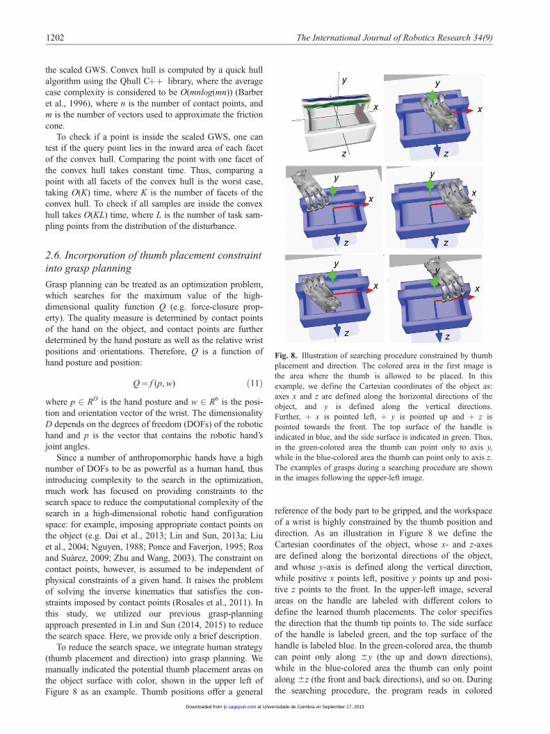
To reduce the search space, we integrate human strategy
(thumb placement and direction) into grasp planning. We
manually indicated the potential thumb placement areas on
the object surface with color, shown in the upper left of
Figure 8 as an example. Thumb positions offer a general
reference of the body part to be gripped, and the workspace
of a wrist is highly constrained by the thumb position and
direction. As an illustration in Figure 8 we define the
Cartesian coordinates of the object, whose x- and z-axes
are defined along the horizontal directions of the object,
and whose y-axis is defined along the vertical direction,
while positive x points left, positive y points up and posi-
tive z points to the front. In the upper-left image, several
areas on the handle are labeled with different colors to
define the learned thumb placements. The color specifies
the direction that the thumb tip points to. The side surface
of the handle is labeled green, and the top surface of the
handle is labeled blue. In the green-colored area, the thumb
can point only along 6y (the up and down directions),
while in the blue-colored area the thumb can only point
along 6z (the front and back directions), and so on. During
the searching procedure, the program reads in colored
Fig. 8. Illustration of searching procedure constrained by thumb
placement and direction. The colored area in the first image is
the area where the thumb is allowed to be placed. In this
example, we define the Cartesian coordinates of the object as:
axes x and z are defined along the horizontal directions of the
object, and y is defined along the vertical directions.
Further, + x is pointed left, + y is pointed up and + z is
pointed towards the front. The top surface of the handle is
indicated in blue, and the side surface is indicated in green. Thus,
in the green-colored area the thumb can point only to axis y,
while in the blue-colored area the thumb can point only to axis z.
The examples of grasps during a searching procedure are shown
in the images following the upper-left image.
1202 The International Journal of Robotics Research 34(9)
at Universidade de Coimbra on September 17, 2015ijr.sagepub.comDownloaded from

vertices of the object model and moves the thumb by
attaching the thumb tip to the colored vertices. The follow-
ing five sub-figures in Figure 8 show the examples of the
feasible grasps found during the searching procedure. For
each thumb placement, the wrist position and orientation
can be computed from the position and orientation of the
thumb tip via forward kinematics. Then, wrist position is
dependent on thumb position as well as on the thumb con-
figurations. Using thumb position as a constraint is a prac-
tical way to reduce the configuration search space so that
the computation of the coverage is feasible.
Once the thumb position is extracted from demonstra-
tion, the wrist position and orientation w can be determined
via forward kinematics by both the pitch of the thumb rela-
tive to the object, and by the thumb joint variables. The
workspace of the wrist is highly constrained by the posture
of the thumb. Therefore, the objective function becomes
Q = f (p, g) ð12Þ
where g is the thumb pitch relative to the object. The search
space of the optimization equals D + 1, where D is the
number of DOFs of the hand joint vector p.
Further dimensionality reduction can be performed on
hand DOFs D using some existing approaches. The idea of
dimensionality reduction on finger joints was proposed by
Santello et al. (1998), who performed principal component
analysis (PCA) on the human hand motion data and
revealed that the first two eigengrasps (mainly flexion/
extension and adduction/abduction) capture more than 80%
of the grasp motion variance, implying a substantial simpli-
fication of hand postures.
Under the constraint of thumb placement, we are able to
use exhaustive search for the optimal grasp. Taking the
Barrett hand for example, with the thumb constraint, the
search space is reduced to five from ten. Given a thumb
placement labeled on the object surface, a number of
potential grasps can be generated by changing the pitch of
the hand relative to the object and hand-joint angles. The
number of grasps to be searched for depends on simulation
settings, such as the resolution of the object model, step
size of the search space, and the physical robotic hand. An
example of power sphere grasp planning by searching
through the subspace of relative pitch is illustrated in
Figure 9. Instead of exhaustive search, further improvement
can be made for the optimization procedure. For detailed
discussion, please refer to our previous work (Lin and Sun,
2014, 2015).
3. Results
3.1. Simulation results
In simulation, we tested our approach for several tasks with
different objects. The data collection of TWC and grasp
planning were programmed with Chai3D and ODE. Non-
expert subjects were asked to manipulate an object in the
user interface via Phantom OMNI. The interactive
wrenches between the object and the environment were
captured during the demonstration with a sample rate of
100 Hz. The data set of the disturbance, compensated for
by object gravity, was recorded. Then, from the data set, a
non-parametric statistical distribution of the disturbance
was built. To reduce the computational complexity, a
smaller set of data points was randomly sampled based on
the non-parametric statistical distribution.
A Barrett hand model and a Shadow hand model were
tested during the simulation for task-oriented grasp plan-
ning. Here, we set the friction coefficient m to be 1. The
friction cone is approximated by an eight-sided pyramid.
For each hand configuration, contact points and contact
normals can be obtained by ODE, and then the GWS can
be computed. Grasp quality Q(G) was calculated based on
the GWS and the distribution of disturbance. The grasp
planning searches for the best grasp configuration that max-
imizes Q(G).
The value of k is computed according to equation (10):
the lower of the values for the task requirement obtained
from the TWC and the capability of the robotic hand. The
task requirement obtained from the TWC is quantified as
the maximum force magnitude of all the data samples in
the TWC. The task requirement indicates the amount of
force we want the robot to apply. If it exceeds the hand
capability, we impose the capability constraint on the con-
tact force.
Figures 10 to 12 show three examples of object manipu-
lation. In the first example, the user was asked to perform a
writing motion with a pencil, where the pencil interacts
with the environment at the tip. The maximum force mag-
nitude in the TWC is 2.6 N, and the hand capability is 20
N, k = min(2.6, 20), therefore k = 2.6. The chosen grasp
should be excellent for balancing the pressure and friction
on the tip. As shown in Figure 10(a) to (c), task wrenches
are biased towards the positive directions of Fy and Fz,
rather than the full space of the friction cone. The resulting
grasp is, therefore, close to the tip. For the hand configura-
tion shown in Figure 10(d), Q(G1) = 0.1969 at k = 2.6,
(a) (b) (c) (d)
(e) (f) (g) (h)
Fig. 9. A procedure of the Shadow hand searching for a power
sphere grasp; (d) is a precision sphere grasp, which is rejected
because it is not a desired grasp type; (h) is a desired power
sphere grasp.
Lin and Sun 1203
at Universidade de Coimbra on September 17, 2015ijr.sagepub.comDownloaded from

meaning it covers 19.69% of task wrenches, which is much
lower than that of Figure 10(e), where Q(G2) = 0.8459 at
the same k, because G2 is better for applying force along
the + Fy and + Fz directions than G1 is. The quality
measures Q(G1) and Q(G2) changing with scale k for the
two grasps are compared in Figure 10(f). The resulting
grasp looks different from a human grasp for a writing task,
since the proposed grasp quality measure evaluates the
grasp only from the perspective of the force requirement,
and the hand kinematics is also different from that of
human hands.
In the second experiment, grasps were compared for
two tasks using a knife. The user was asked to perform a
cutting motion along one direction ( + x marked in red in
Figure 11) and a butter-spreading motion using both sides
of the blade. The disturbance distributions for the two tasks
are reported in Figure 11(a) to (d). As shown for the cutting
task in Figure 11(a), a grasp should be able to generate
pressure along the 2z direction and friction mainly along
the + x direction of the blade. Torque generated along
with the force is shown in Figure 11(b). For the butter-
spreading task shown in Figure 11(c) and (d), the task
wrenches cover a partial area of two opposite friction
cones, in other words, the grasp should be able to apply
pressure along both + y and 2y, and friction along + z.
The thumb placement is constrained to the handle. Figure
11(e) to (g) contains evaluations of three grasps for the two
tasks (Q1 for the cutting task and Q2 for the butter-
spreading task). For the cutting task, the scale k is set to be
8.04 and larger than k = 3.25 for the butter-spreading task,
selected by the maximum force magnitude in the TWC. It
can be seen that for the cutting task the hand configuration
in Figure 11(e) is better to apply force in 2Fz, along with
2Ty. The hand configuration in Figure 11(g) has the worst-
quality measure of the three due to its deficient ability to
apply force along the z direction, whereas for the butter-
spreading task, the hand configuration in Figure 11(g) is
the best and that in Figure 11(e) is the worst.
In the third task, the user was asked to strike a plane
with a hammer, and the grasp planning was performed to
compare the results of the Barrett hand model and the
Shadow hand model. It can be imagined that the chosen
grasp should be excellent for balancing large pressure on
the head of the hammer. As shown in Figure 12(a) and (b),
the distribution covers almost the whole space of the fric-
tion cone, whose axis is along the + z direction, and the
pressure between the hammer and the environment along
the + z direction is as large as 20 N. The designated grasp
type during grasp planning is a power grasp in order to per-
form powerful manipulation. The task requirement exceeds
the hand capability, and therefore the scale k of the GWS is
set to be the hand capability of 20 for the computation of
the quality measure. Figure 12 show the results of search-
ing through the feasible area of thumb placement for the
Barrett hand model (Figure 12(c) to (g)) and for the
Shadow hand model (Figure 12(h) to (k)). It can be seen
that the grasp that is closer to the head is better for counter-
balancing the forces that occur at the head. Note that the
result for the hammer grasp is different from the intuitive
grasping style of humans, who prefer to hold the handle on
the other side away from the head, because humans desire
to reach a large swing motion with a relatively small arm
motion, as well as to generate a large impact force. The
grasp optimization considers only the ability to apply
Fig. 10. Planning results for a writing task with a pencil. The center of mass is set to be the origin of the coordinate frame, where
axes x, y, and z are indicated in red, green and blue (shown in (d) and (e)). (a) to (c) Distribution of task wrench projected to Fx–Fy,
Fx–Fz, Ty–Tz subspaces, respectively, where the task wrench is distributed mainly along the Fx, Fy and Fz directions; torque Tz is
small so it is not reported here. (d) and (e) Two different hand configurations; (f) grasp quality Q versus scale k for the two hand
configurations shown in (d) and (e).
1204 The International Journal of Robotics Research 34(9)
at Universidade de Coimbra on September 17, 2015ijr.sagepub.comDownloaded from

finger contact force other than the arm and wrist motions.
It can be observed from the figure that similar results were
obtained for the two hand models.
As concluded from the experiments, the resulting
grasp with a higher grasp-quality criterion tends to be
more efficient in applying frequently occurring force,
using the same magnitude of resultant force as the low-
quality grasp, thus improving the efficiency of power
consumption.
3.2. Experimental results on a real platform
Experiments were also performed with a real robot system
composed of a Barrett robotic hand and a six-DOF FANUC
LR Mate 200iC robotic arm. The Barrett hand is a three-
fingered grasper with four degrees of freedom. The system
is shown in Figure 13.
In the experiment, objects and manipulation tasks were
carefully selected to evaluate the proposed approach. First,
because we focused on the success rate of the resulting
grasps in executing manipulation tasks rather than simple
pick-up tasks, we did not consider tiny objects, such as a
pen and a scoop, due to the physical limitation of the
Barrett hand in gripping tiny objects precisely. Also, only
representative tasks were considered to avoid repetitive
tasks. As a result, three representative manipulation tasks
were selected to evaluate the proposed approach, including:
� Task 1: move a computer mouse on a table;� Task 2: plug a power adapter into a power strip;� Task 3: screw a light bulb into a socket.
Task 1 represents a sliding interaction with the environ-
ment. Similar tasks include using a dry-erase eraser,
Fig. 11. Planning results for a cutting task and a butter-spreading task with a knife. (a) and (b) Cutting task distribution of task
wrenches projected to Fx–Fy–Fz and Tx–Ty–Tz subspaces, respectively, where the task wrenches are distributed mainly in 2Fz and
Fx. (c) and (d) Corresponding task wrench distribution for butter-spreading task, where the task wrenches are distributed primarily
in + Fy, 2Fy, + Fz, + Tz, 2Tz. (e) to (g) Three different hand configurations; Q1 is the quality measure for the first task, and Q2
is the quality measure for the second task. Scale k is set to be 8.04 and 3.25 for the two tasks for precision grasp planning.
Lin and Sun 1205
at Universidade de Coimbra on September 17, 2015ijr.sagepub.comDownloaded from

Fig. 12. Planning results for a hammer, where a power grasp is searched for because high power is needed. (a) and (b) Distribution of
task wrenches projected to Fx–Fy–Fz and Tx–Ty–Tz subspaces, respectively, where the task wrenches are distributed mainly in Fz and
Ty. (c) to (g) Five different hand configurations of the Barrett hand model. (h) to (k) Four different hand configurations of the Shadow
hand model. Scale k is set to be 20.
Fig. 13. Snapshots of the robot execution. Top row: the robot approached the mouse, grasped it, and moved it on the table. The
whole procedure was done autonomously. Middle row: the robot approached the power adapter, grasped it, and lifted it up
autonomously. Then, teleoperation by Phantom OMNI was enabled, and the manipulation task was performed by the user. Bottom
row: the bulb was screwed into a socket. The whole procedure setting was similar to the plug manipulation.
1206 The International Journal of Robotics Research 34(9)
at Universidade de Coimbra on September 17, 2015ijr.sagepub.comDownloaded from

moving a broom or a vacuum cleaner on the floor, painting,
and so on. Task 2 represents a peg-in-hole motion. Similar
tasks include inserting a key or a flash drive, and so on.
Task 3 represents a screwing motion. Similar tasks include
screwing a screwdriver, jar lid, knob, key, switch, and so
on.
Each task was executed in 10 trials. The target object
was placed at the same known location and orientation in
the robot’s workspace for each trial. Before each execution,
the robot arm was reset to an initial position, and the robotic
hand was kept open. The execution procedure was divided
into four steps, as illustrated in Figure 13. The first step
was to approach the target object and reach the wrist posi-
tion and orientation relative to the object which resulted
from the algorithm. To avoid potential collision, the robot
first moved to 200 mm higher than the target pose, then
went straight down until it reached the target pose. Then,
the robotic hand was commanded to close its fingers on the
object and lift the object up from the table. These first two
steps were performed autonomously. The next manipulation
step was executed either autonomously or guided by
humans, depending on the complexity of the manipulation.
The first task, that is, moving a mouse around on a table,
was relatively simple, so it was executed in a predefined
routine, in which the mouse was moved along a square path
on the table. The other two tasks, however, required a com-
plicated sensing and manipulating technique to accomplish
the task, which is beyond the focus of this paper. Therefore,
we introduced human participation to completing the
remaining task by teleoperating the robot using a haptic
device, Phantom Omni. After the manipulation step was
accomplished, the robot hand was then commanded to open
its fingers and move up and away from the object.
The Omni device was chosen due to its compact design
and the intuitive positional abilities that we felt would be a
good choice for the teleoperation of the robotic arm. The
FANUC arm and Barrett hand were connected to the same
PC with the Phantom Omni. The manipulator was teleoper-
ated in a position-based and bilateral mode, for which force
feedback was provided to the user. The positions and gim-
bal angles of the OMNI stylus were continuously trans-
mitted to the PC server in real time. The position and
orientation of the OMNI stylus were transformed to the
corresponding position and orientation of the robot end-
effector in its feasible workspace. The robot arm and hand
incorporate their own motion controllers. The position
commands were streamed from the PC server to the robot
controller, so the manipulator was able to follow the OMNI
motion in real time. For safety, the speed was constrained
up to a feed rate of 30% of the maximum speed. The force
sensed by the force sensor embedded in the robot wrist was
fed back to the OMNI, so the user was able to feel the con-
tact force when the manipulator was in contact with the
environment.
To evaluate the proposed quality measure on a physical
robotic platform, we compared the success rate with that of
the widely used non-task-oriented planning method that
optimizes the epsilon quality e (Ferrari and Canny, 1992).
The epsilon quality e measures the radius of the largest six-
dimensional ball centered at the origin and enclosed with
the convex hull of the UGWS. The epsilon quality refers to
the magnitude of the disturbance wrenches that can be com-
pensated for by the grasp in the worst case. The larger the
epsilon quality, the more stable the grasp in terms of resist-
ing the worst-case disturbance. We did not compare it to the
quality measure km discussed above, because it is not trivial
to find such an absolute scale of km to fit the entire TWS
into the GWS without simplifying the shape of the TWS.
We did not compare the results with other task-oriented
methods either, because to the best of our knowledge none
of the related research on task-oriented grasp planning has
reported any success rate on the execution of manipulation
tasks in a physical system. Most work on real robotic plat-
forms only tested pick-up tasks.
The grasps were being searched for and evaluated by
the epsilon quality measure and our proposed quality mea-
sure under the same constraints of thumb placement area
and grasp types. The resulting hand configurations from
both the proposed grasp quality measure and the non-task-
oriented grasp quality measure are shown in Figure 14.
The first two columns show the optimal grasps resulting
from our approach and the epsilon quality measure, with
both of the two quality metrics Q and e marked in each
corresponding figure. Column 3 and column 4 compare
the coverage of the TWC by the two grasps shown in the
first two columns. In the figures, the wrench samples in the
GWS are marked by blue points, while the wrench samples
outside the GWS are marked by red circles. Again, the
scale k of the marked quality metric Q was chosen by
equation (10). The fifth column shows the proposed task-dis-
turbance-based grasp quality Q as a function of scale k for the
two grasps. Since grasps in column 1 are those that maximize
our proposed Q and grasps in column 2 are those that maxi-
mize e, Q(G1) in column 1 is greater than Q(G2) in column
2, while e(G1) in column 1 is less than the corresponding
value in column 2.
The execution on a real robotic platform of resulting
grasps from both the proposed grasp quality measure and
the non-task-oriented grasp quality measure for all of the
three tasks were compared in Figure 15, and the success
rates of the resulting grasps for both quality measures were
compared in Table 1. The three examples are also shown in
Table 1. Comparison of success rates of proposed approaches
using task disturbance with those of the non-task-oriented
approach.
Task Success rate oftask-disturbance-basedgrasp planning
Success rate ofnon-task-orientedgrasp planning
Task 1 60% 40%Task 2 80% 70%Task 3 70% 20%Overall 70% 43.3%
Lin and Sun 1207
at Universidade de Coimbra on September 17, 2015ijr.sagepub.comDownloaded from
the supplemental video of Multimedia Extension 1. If the
object slid out of the robotic hand during the task execution
because of outside disturbance from collision, it was
counted as a failure. Otherwise, if the robot successfully
completed the task without dropping the object, it was
counted as a success. It can be observed that, overall, hand
configurations resulting from the proposed quality measure
have a higher success rate (average of 70%) compared to
that of the non-task-oriented grasp quality measure (aver-
age of 43.3%) in executing the manipulation tasks.
The results imply that the proposed quality metric is
more consistent with the success rate of the manipulation
tasks than the non-task-oriented quality metric.
Task 1 required the robot to slide the mouse on a plane
while maintaining contact with the plane. The disturbance
was distributed mainly on the boundary of the friction cone
(row 1, column 3 in Figure 14), so the grasp was to coun-
teract the friction sliding on the plane and the support force
from the plane. Both resulting hand configurations grasped
the mouse on the side face (row 1, columns 1 and 2 in
Figure 15), but in the latter hand configuration, the fingers
were closer to the bottom edge. It was observed in the
experiment that in the latter hand configuration the mouse
was easier to slide up from the fingers during execution,
because the side faces were inclined inward. In Task 2, both
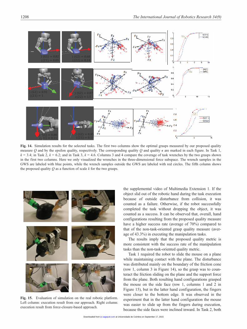
Fig. 14. Simulation results for the selected tasks. The first two columns show the optimal grasps measured by our proposed quality
measure Q and by the epsilon quality, respectively. The corresponding quality Q and quality e are marked in each figure. In Task 1,
k = 3.4; in Task 2, k = 6.2; and in Task 3, k = 4.6. Columns 3 and 4 compare the coverage of task wrenches by the two grasps shown
in the first two columns. Here we only visualized the wrenches in the three-dimensional force subspace. The wrench samples in the
GWS are labeled with blue points, while the wrench samples outside the GWS are labeled with red circles. The fifth column shows
the proposed quality Q as a function of scale k for the two grasps.
Fig. 15. Evaluation of simulation on the real robotic platform.
Left column: execution result from our approach. Right column:
execution result from force-closure-based approach.
1208 The International Journal of Robotics Research 34(9)
at Universidade de Coimbra on September 17, 2015ijr.sagepub.comDownloaded from

the success rate and the quality Q as a function of scale k
are close to each other, although they gripped the object on
different faces. The success rates of both approaches
appeared to be similar as well. In Task 3, in the latter hand
configuration resulting from the non-task-oriented
approach, the other two fingers were closer to the base than
the thumb. When the robot was trying to screw the bulb
into a socket, it was fairly easy for the bulb to be dropped
by the robot. In Task 3, the success rate of our approach
was much higher than that of the non-task-oriented
approach, demonstrating its higher capability to resist the
task disturbance.
4. Conclusion
For task-oriented grasp planning, manipulation tasks are
known to be difficult to model. In this study, a manipula-
tion task was modeled by building non-parametric statisti-
cal distribution of disturbance from demonstration data.
Studies on disturbance data indicate that the task wrench is
not evenly distributed. Instead, it is possible that distur-
bance wrenches in some directions occur more frequently
than in the other areas, even if they may be smaller than
wrenches that occur less frequently. In favor of grasps that
are able to apply frequently occurring forces, this paper
proposes a task-oriented grasp quality criterion based on
the distribution of the task disturbance by computing the
ratio of disturbance a grasp covers.
The approach has been validated in simulation with a
Barrett hand and a Shadow hand. Both the task model and
the demonstration are independent of hand models, so they
can be used for other robotic hands. The presented
approach was also evaluated with a real robotic system to
compare with the non-task-specific automatic grasp plan-
ning. Results verify the consistency of the success rate with
the proposed disturbance-based quality metric.
There are several limitations to the approach. We mod-
eled the grasp only by contact locations without consider-
ing hand configurations. This raises the problem that the
contact force may not be applicable by finger joints if they
are in ‘‘bad’’ configurations. Some existing works have pro-
posed grasp quality metrics by hand configurations, such
as manipulability: the ability of the manipulator to impart
arbitrary motions at the end-effector (Yoshikawa, 1985). It
can be combined with our proposed quality measure as a
global grasp quality measure to give a more complete eva-
luation of a grasp.
The pen and hammer examples in simulation imply that
the resulting robotic grasps may be different from the intui-
tive grasps of humans, because not only do robots have dif-
ferent hand kinematics than humans, but humans also
consider more than the force requirements of a task, for
example, motion of the hand and arm to realize the tool
actions. Therefore, including both arm and hand motion
factors in grasp planning can be a direction of future work.
In addition, the TWC can also be updated by the real data
collected in robotic manipulation to improve the grasp
planning on the fly, given that we cannot guarantee that the
TWC during robot execution is always the same as the
demonstrated TWS.
Funding
This research received no specific grant from any funding agency
in the public, commercial, or not-for-profit sectors.
References
Aleotti J and Caselli S (2010) Interactive teaching of task-oriented
robot grasps. Robotics and Autonomous Systems 58(5):
539–550.
Barber CB, Dobkin DP and Huhdanpaa HT (1996) The Quickhull
algorithm for convex hulls. ACM Transactions on Mathemati-
cal Software 22(4): 469–483.
Bicchi A and Kumar V (2000) Robotic grasping and contact: A
review. In: IEEE international conference on robotics and
automation, pp. 348–353.
Billard A, Calinon S, Dillmann R, et al. (2008) Robot program-
ming by demonstration. In: Siciliano B and Khatib O (eds)
Handbook of Robotics. Cambridge, MA: MIT Press.
Borst C, Fischer M and Hirzinger G (2004) Grasp planning: How
to choose a suitable task wrench space. In: IEEE international
conference on robotics and automation, pp. 319–325.
Brock O, Kuffner J and Xiao J (2008) Motion for manipulation
tasks. In: Siciliano B and Khatib O (eds) Springer Handbook
of Robotics. Berlin: Springer.
Dai W, Sun Y and Qian X (2013) Functional analysis of grasping
motion. In: IEEE/RSJ international conference on intelligent
robots and systems.
Ferrari C and Canny J (1992) Planning optimal grasps. In: IEEE
international conference on robotics and automation, pp.
2290–2295.
Han L, Trinkle JC and Li ZX (2000) Grasp analysis as linear
matrix inequality problems. IEEE Transactions on Robotics
and Automation 16(6): 663–674.
Haschke R, Steil JJ, Steuwer I, et al. (2005) Task-oriented quality
measures for dextrous grasping. In: IEEE international sympo-
sium on computational intelligence in robotics and automa-
tion, pp. 689–694.
Hsiao K, Ciocarlie M, Brook P, et al. (2011) Bayesian grasp plan-
ning. In: ICRA workshop on mobile manipulation: Integrating
perception and manipulation.
Hueser M and Zhang J (2008) Visual and contact-free imitation
learning of demonstrated grasping skills with adaptive envi-
ronment modelling. In: IEEE/RSJ international conference on
intelligent robots and systems, WS on grasp and task learning
by imitation.
Kirkpatrick D, Mishra B and Yap CK (1992) Quantitative Stei-
nitz’s theorems with applications to multifingered grasping.
Discrete & Computational Geometry 7(1): 295–318.
Kruger H and van der Stappen AF (2011) Partial closure grasps:
Metrics and computation. In: IEEE international conference
on robotics and automation, pp. 5024–5030.
Kruger H and van der Stappen AF (2013) Independent contact
regions for local force closure grasps. In: IEEE international
conference on robotics and automation, pp. 1588–1594.
Lin and Sun 1209
at Universidade de Coimbra on September 17, 2015ijr.sagepub.comDownloaded from

Kruger H, Rimon E and van der Stappen AF (2012) Local force
closure. In: IEEE international conference on robotics and
automation, pp. 4176–4182.
Lin Yand Sun Y (2013a) Grasp mapping using locality preserving
projections and kNN regression. In: IEEE international confer-
ence on robotics and automation, pp. 1076–1081.
Lin Y and Sun Y (2013b) Task-oriented grasp planning based on
disturbance distribution. In: International symposium on
robotics research, pp. 1–6.
Lin Y and Sun Y (2014) Grasp planning based on grasp strategy
extraction from demonstration. In: IEEE/RSJ international
conference on intelligent robots and systems, pp. 4458–4463.
Lin Y and Sun Y (2015) Robot grasp planning based on demon-
strated grasp strategies. The International Journal of Robotics
Research 34(1): 26–41.
Lin Y, Ren S, Clevenger M, et al. (2012) Learning grasping force
from demonstration. In: IEEE international conference on
robotics and automation. pp. 1526–1531.
Liu G, Xu J, Wang X, et al. (2004) On quality functions for grasp
synthesis, fixture planning, and coordinated manipulation.
IEEE Transactions on Automation Science and Engineering
1(2): 146–162.
Li Z and Sastry SS (1988) Task-oriented optimal grasping by mul-
tifingered robot hands. IEEE Journal of Robotics and Automa-
tion 4(1): 32–44.
Miller AT, Knoop S, Christensen HI, et al. (2003) Automatic grasp
planning using shape primitives. In: IEEE international confer-
ence on robotics and automation, pp. 1824–1829.
Murray RM, Li Z and Sastry SS (1994) A Mathematical Introduc-
tion to Robotic Manipulation. Boca Raton, FL: CRC press.
Nguyen VD (1988) Constructing force-closure grasps. The Inter-
national Journal of Robotics Research 7(3): 3–16.
Pollard NS (1994) Parallel methods for synthesizing whole-hand
grasps from generalized prototypes. PhD Dissertation, Depart-
ment of Electrical Engineering and Computer Science, Massa-
chusetts Institute of Technology, Cambridge, MA.
Pollard NS (2004) Closure and quality equivalence for efficient
synthesis of grasps from examples. The International Journal
of Robotics Research 23(6): 595–613.
Ponce J and Faverjon B (1995) On computing three-finger force-
closure grasps of polygonal objects. IEEE Transactions on
Robotics and Automation 11(6): 868–881.
Roa MA and Suarez R (2009) Finding locally optimum force-
closure grasps. Robotics and Computer-Integrated Manufac-
turing 25(3): 536–544.
Romero J, Kjellstrom H and Kragic D (2008) Human-to-robot
mapping of grasps. In: IEEE/RSJ international conference on
intelligent robots and systems, WS on grasp and task learning
by imitation.
Rosales C, Ros L, Porta JM, et al. (2011) Synthesizing grasp con-
figurations with specified contact regions. The International
Journal of Robotics Research 30(4): 431–443.
Sahbani A, El-Khoury S and Bidaud P (2012) An overview of 3D
object grasp synthesis algorithms. Robotics and Autonomous
Systems 60(3): 326–336.
Santello M, Flanders M and Soechting J (1998) Postural hand
synergies for tool use. The Journal of Neuroscience 18(23):
10,105–10,115.
Suarez R, Cornella J and Garzon MR (2006) Grasp quality mea-
sures. Technical report no. IOC-DT-P 2006–2010. Institut
d’Organitzacio i Control de Sistemes Industrials.
Wilk MB and Gnanadesikan R (1968) Probability plotting meth-
ods for the analysis for the analysis of data. Biometrika 55(1):
1–17.
Yoshikawa T (1985) Manipulability of robotic mechanisms. The
International Journal of Robotics Research 4(2): 3–9.
Zhu X and Wang J (2003) Synthesis of force-closure grasps on 3-
D objects based on the Q distance. IEEE Transactions on
Robotics and Automation 19(4): 669–679.
Appendix: Index to Multimedia Extension
Archives of IJRR multimedia extensions published prior to
2014 can be found at http://www.ijrr.org; after 2014 all
videos are available on the IJRR YouTube channel at http://
www.youtube.com/user/ijrrmultimedia.
Table of Multimedia Extension
Extension Media type Description
1 Video Experiments of the three tasksconducted in Section 3.2.
1210 The International Journal of Robotics Research 34(9)
at Universidade de Coimbra on September 17, 2015ijr.sagepub.comDownloaded from