graphics interface '82graphicsinterface.org/wp-content/uploads/gi1982-29.pdfthe system allows...
TRANSCRIPT
AN ADVANCED DATA GENERATION SYSTEM FOR USE IN COMPLEX OBJECT SYNTHf.SIS FOR COMPUTER DISPll\Y
Wayne E. Carlson
The Ohio State University Computer Graphic s Research Group
Columbus, Ohio
ABSTRACT
An integrated system for the creation and modification of three dimensionCl I datil for use in imilC'W synthesis is described. The hierarchical organization of the system functions is shown, and several of these functions are detailed. The system is designed so that a user can create a large class of three dimensional objects in an intuitive fashion without an extensive knowledge of the internal workings of the software and the associated data structure .
KEYWORDS: da ta genera tion, combina toria I geometry, lofting, surface of revolution, object synthesis, user interface, surface patches.
1. INTRODUCTION
The Data Generation system (DG) represents an integrated approach to the creation and modification of complex two and three dimensional data for ultimate use in image synthesis. The system uses many traditional and state of the art algorithms in the construction of objects. By utilitizing a common data structure throughout, and by organizing control in a hierarchical tree, the system allows the user a high degree of flexibility and ease in the creation of such objects. Interaction with the system is accomplished via a data tablet in conjunction with a vector display device.
Surface creation is accomplished by first crea ting a two dimensional curve or curves, which are used to control the algorithmic creation of the three dimensional surface . These algorithms include lofting between contours, projection of a closed curve, surface of revolution, and fleshing out a skeleton to create a tubular object.
Surface modification is performed interactively with algorithms that allow for the movemen t of a poin t or s et of poin ts (warping) and
This research was supported in part by National Science Foundation Grant Number MCS 7923670.
bending an object through the use of an internal skeleton. Combinatorial algorithms are available for joining object surfaces.
All capabilities of DG are included in one or more menus. The menu appropriate to the Clctive node in the control hierarchy is always displayed for the user. All messages, including instructions to the user and error messages, as well as informative messages like slide values, are also displayed on the display. The user selects a menu item, which represents a loca 1 func tion or a reques t to move to another tree level, by placing a cursor and pressing a function switch on the cursor puck of the data tablet. This action either causes the function to be performed, leaves the system in an interactive input mode, or displays a new menu from th e next or previous tree level .
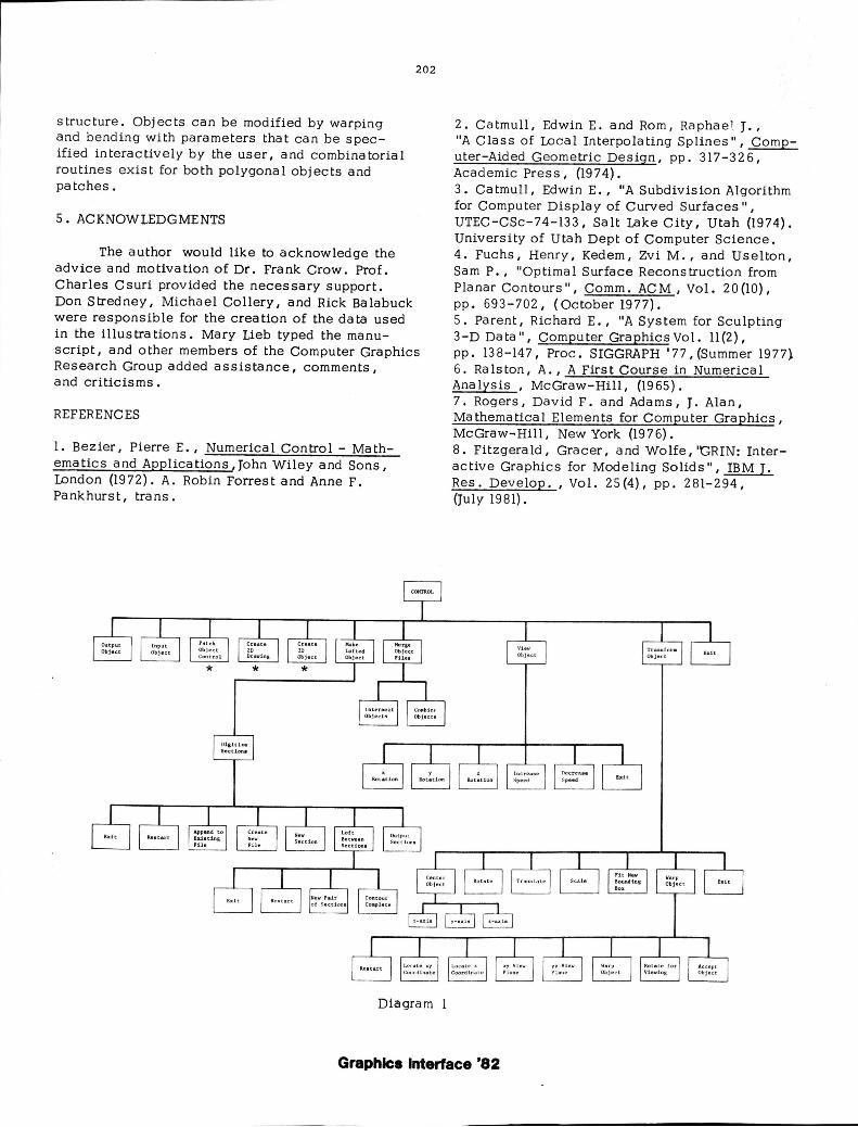
2. SYSTEM ORGANIZATION
The system capabilities and the corresponding trees are shown on the following qiagrams. Nodes in the first figure marKed with an asterisk (*) are detailed in another figure, representing a complete subtree.
2.1 CONTROL
When the progra m is initia ted by the us er, control is initialized to the node "CONTROL", which represents the root of the tree. At this level, the user can choose to create a new
Graphics Interface '82

object, input a previously created object, merge two or more objec ts into one, view the object from several different vantage points , modify the object, or output an object description.
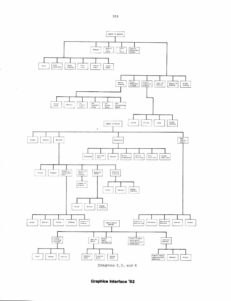
2.2 CREATION OF 2D DRAWINGS
A typica 1 interactive session begins with interactive ly drawing or otherwise crea ting a two dimensional open or closed curve, which is then either treated as an object itself or used to control the crea tion of a three dirrensional object. The second diagram represents the subtree associated with this process .
On trans ition to this node of the tree, the user has a large number of options available to him or her. The drawing process is aided by the display of several different resolutions of the displ ayed axis. This allows the user to draw at varying levels of accuracy. A previous ly defined objec t can be displayed at a lower intensity as a background object, so that the new drawing can maintain a related shape or proximity. This helps in the consecutive "building" process , where obj ec t parts are created in the appropria.te position and merged in the previous node . A stack is maintained so that the current environment can be stored (pushed) or restored 'popped), making it much easier to accept or reject changes to the drawing . This environmen t includ es all relevent object information, all current transformations, and all ac tive switches and their values.
When the user makes the decision to enter the interactive "draw" mode, he or she interacts via the tablet and cursor. Whenever the function switch is depressed and the cursor is determined to be outSide of the menu area , the cursor coordinates are stored in the object data structure. An edge is drawn from the previous coordinates to the new coordinates . This data structure can be modified by deleting a point nearest the cursor, inserting a point at the cursor between the coordinates defining the nearest edge, or interactively warping (rubber banding) an edge or edges by moving the point closest to the cursor.
2.2.1 SMOOTHING
The two dimensional drawing can be us ed as a con trol function for one of several smoothing algorithms. We have chosen two interpola tion schemes and two approximation schemes. Each
198
has its own characteristics to provide :.he maximum flexibility .
The two approximating techniques include a standard cubic b -spline algorithm and a Bezier (Bernstein) formulation resulting in a degree n-l polynomial (1). An interpolatory scheme is used which utilizes the cardinal spline basis with a fomulation attributed to Catmull and Rom (2). We also use the Hermite polynomials with some additional control as described below.
Once the deSired two dimensional drawing is created and is acceptable to the user, control returns to the root and the data structure is accordingly updated. It is important to note that at all levels of the user hierarchy, a copy of the permanen t data structure is used for all interactive processing . It becomes the permanent data structure only when the user accepts it.
The user can choose to restart any process in the system at any time . There is, however, a certain amount of protection built in. Any time the function selection may make a modifica tion to the permanent data structure, the system will make certain the user wants to perform the function requested by asking for verification. This prevents accidental selection of some very destructive functions, like restart and exit, that might undesirably modify the data structure .
2.2.2. HERMITE INTERPOlATION WITH ADDITIONAL CONTROL
Hermite interpolation is a piecewise interpolation technique using as a basis the Hermite polynomials (6). It us e s a s the necessary constraints the endpoin ts of a set of relevant line segments and the first deriva tive va lues at those endpoints . The line segm en ts are taken from the defining function as appropriate. The first and last segments are extrapolated to provide the information necessary for the boundary conditions. We use cubic polynomials as the basis function s , so any point on the smoothed curve can be given by
h(t) = f (tO)HO(t) + f (tl)Hl (t) + f' (to)HO(t) + f' (t l)H l (t)
where f(t O)' f(t l), f' (to)' and f' (t l) are the e ndpoints
and their first derivativ es, respec tively, and
HO' HI' HO, and HI are the basis functions.
Graphics Interface '82
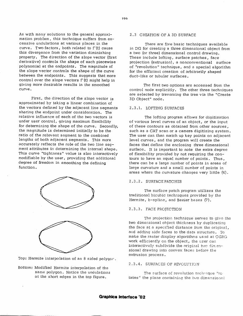
As with many solutions to the general approxima tion problem, this technique suffers from excessive undulations at various places in the curve. Two factors, both related to f'(t) cause this divergence from the variation diminishing property. The direction of the slope vector (firs t derivative) controls the shape of each piecewise polynomial at the endpoints. The magnitude of the slope vector controls the shape of the curve between the endpoints. This suggests that more control over the slope vectors f' (t) might help in giving more desirable results in the smoothed curve.
First, the direction of the slope vector is approximated by taking a linear combination of the vectors defined by the adjacent line segments sharing the endpoint under conSideration. The relative influence of each of the two vectors is under user control, giving maximum flexibility for determining the shape of the curve. Secondly, the magnitude is determined initially to be the ratio of the relevant segment to the combined lengths of both adjacent segments. This more accura tely reflec ts the role of the two line segment attributes in determining the internal shape. This curve "tightness" value is also interactively modifiable by the user, providing tha t additiona 1 degree of freedom in smoothing the defining function.
Top: Hermite interpola tion of an 8 sided polygof' .
Bottom: Modified Hermite interpolation of the same polygon. Notice the undulation s a t the short edges in the top figure.
199
2.3 CREATION OF A 3D SURFACE
There are five basic techniques available in DG for creating a three dimensional object from a two (or three) dimensional control drawing. These include lofting, surface patches, face projection (extrusion), a nonconventional surface of "revolution" technique, and a special algorithm for the efficient creation of arbitrarily shaped duct-like or tubular surfaces.
The first two options are accessed from the control node explicitly. The other three techniques are selected by traversing the tree via the "Create 3D Object" node.
2.3.1. LOFTING SURFACES
The lofting program a llows for digitiza tion of various level curves of an obj ect, or the input of these contours as obtained from other sources, such as a CAT scan or a camera digitizing system. The user can then match up key points on adjacent level curves, and the program will create the faces that define the enclosing three dimensional surface. It is important to note the extra degree of flexibility provided by not requiring the contours to have an equal number of points. Thus, there can b e a large number of points in areas of large curva ture a nd a s ma 11 number of poin ts in areas where the c urvature changes very little (4).
2. 3 .2. SURFACE PATCHES
The surfa ce patch program utilize s the traditional b ic ub ic tec hniques provided by the Hermite, b- s pline , and Bezier ba s es (7).
2.3. 3. FACE PROJEC TION
The proj ec tion techniq ue serves to give the two dimensional obje ct thickness by d uplic a ting the fa c e at a s pec ifi ed dis tanc e from the origina l, a nd adding side fa ces to the da ta structure . To make the raster d i s play algorithms uS3d at CGRG work effic ien tly on the obj ec t, the user can interactively s ubd ivide the original tVIO din.8rl -· sional drawing into c onvex fa ces before t he extrusion proc e s s.
2.3 .4. SURFACES OF REVOLUTIO N
The s urface of revolution tecnr~ iq ue "ro ta te s" the plane containing the t"JO dimensio .1aJ
Graphics Interface '82
drawing around the (vertica 1) axis in a specified fashion. It is nonconventional for two reasons. First, standard solid of revolution techniques rota te a profile around an axis in a circle, generating a surface that is axially symmetric around the axis. Any horizontal cross section of the obj ect will be a circle. We a llow a "pa th" of revolution to be a circle, an ellipse, and in fact, any closed two dimensional shape that can be drawn by the user at the "Draw 2D Object" node described earlier. Moreover, the path needn I t be centered a t the axis, and in fact more than one path can be specified. If there is more than one path, the user can interactively position them on the original two dimensiona 1 control profile, and a linear interpolation is done between them.
Second, there can be more than one control profile used in conjunction with the above paths. These profiles are drawn by the user, and can be positioned around the axis. In this ca se, a single profile is not revolved around the axis. Instead, the surface is generated by applying a blending function to the two appropria te consecutive profiles.
2.3.5. CREATION OF DUCTS
A tubular object is made by first creating a two dimens iona 1 curve in the draw routine. If desired, this piecewise linear curve can be made into a three dimensional space curve using the warp rou tine. To genera te the tubular obj ec t comprising the duct, we perform the following:
A vector of absolute or varying length, specified by the user, is calculated at each point on the curve. This is done by taking a linear combina tion of the vectors defining the adjacent edges of the piecewise linear curve. The magnitude of the vector is normalized if the duct should have a regular thickness throughout. If not, the relative magnitude of the vector controls the thickness of the object at tha t cross section. This vector is rotated around the axis defined b~' adjacent segments of the curve in the same fashion as described above. The new faces that are thus created are entered into the object data structure.
2.4. OBJECT MODIFICATION
Once a three dimensional object has been
200
created using these techniques, it can ')e modified in the following wa ys. Two differen t three dimensiona 1 obj ects can be merged into one by joining faces within a specified proximity or faces with common vertex points. Alternatively, the two object files can be joined without adding or deleting any faces.
2.4.1. POLYGON INTERSECTION
An a Igorithm is used which ca lcula tes the intersection of two overlapping closed polyhedral surfaces, and subsequently describes a third object which consists of polygons from the original two objects and new ones created by the intersection. This collection of polygons is subject to a set of combinatorial operators which determine the final object. These operators form a third which is the intersection of the first two, the union of the two, or the result of one cutting the other. The power of the algorithm lies in its interactive nature and the fact that it handles concave polygons as well as those which are convex (5).
2.4.2. PATCH INTERSECTION
A similar algorithm can intersect pairs of objects defined by Bezier patches. A modified Catmull recursiv e subdivision (3) is performed on each obj ect, and subpatches are either discarded if they do not participate in the intersection, or con sidered further. Pa tches are subdivided until a relevant subpatch is planar to within a pred efined e psilon , as determined by the relative planarity of the polygon mesh defining the subpa tch. The resulting intersection space curve can be outpu t as part of the patch d es cription for '..I s e by a pa tch dis p la y algorithm . Alternativ e ~y , the "planar" polygons ob ta ined In the subdivision process ca n be used with the space c urv e to output a polyhedral a pprox imation to the obj ecL
This a pproximatio n has la rge numbers of polygons i n a reas of high curva ture, ana tewer polygons in re la tiv el y fla t a reas . Thus , the re sulting ob je c t can be le ns G0rr,plex tha n a r~gu la r po lygona l a pproxi m:uiol1 o f .:'l pa tch Ll,"3 ':lE: -:I
(Jbjec t .
We are i nv e stigating tr.e use of s10 pc va lues a t the in ters ection curve to provide for the in troduc tion of smooth f1ile ts into ti-te jn t ~' · ·
Graphics Interface '82
sected objects (for example, at the intersection of a wing and fuselage of an aircraft that is defined with patches).
2.4.3. WARPING
A two or three dimensional object can be warped in space by picking a control point using the cursor puck. A parameter for distance is given which indicates which vertices in the data structure will be moved with the control point (Le., all connected vertices within that Euclidean dis tance) . Fina lly, a parameter for weight is given which determines how much those points will be moved. The points will be moved a decreasing amount with an increasing original distance. If the weight is low, the further points will be moved less, and if it is high, they will be moved (nearly) the same as the control point.
More forma lly, le t d be the specified Euclidean distance, and w the specified weight. Let (x,y,z) be the selected warp control point. Then a 11 edges emana ting from (x, y, z) are traversed, and any point (x' ,y' ,z') encountered while still at a distance d' less than d units from (x,y,z) is entered into a list along with the distance d'. Let dx be the delta movement in the x direction (relative to (x,y,z)). Then (x~ y' ,z') will be moved a distance dx', where
d' 2-w dx * (1 - - ) if w < 0
d
dx' d' dx * (1 - - ) if w = 0
d
dx * (1 _ (~') 2w )
d if w > 0
Notice tha t as w approaches the maximum positive limit, the weighting value gets close to 1. As it approaches the negative limit, the value goes to o. If the weight parameter is 0, the value changes linearly with the distance from the control point. The object can be warped with respect to any combination of the three dimensions. At any time, the user can rotate it around the three axes to view the change from all positions.
201
2.4.4. BENDING
The bending routine works by first mapping the surface points to a user defined skeleton. The skeleton is modified according to the bend that is desired, and the points related to the skeleton by the mapping process are redefined according to the new positions of the skeletal segments. The process is powerful yet has a very efficient and flexible user interface. Earlier implementations of both warp and bend algorithms for polygonal objects are given in more detail in (5).
3 . IMPLEMENTATION
The system in its present configuratio n has been used at CGRG for the last eight months. It has been implemented on a Digital Equipment Co. VAX 11/780 using a Megatek 7000 seri~ s display device that includes three dimensional capabilities and hardware translation, rotation, scale, and clipping. Interaction with the display is accomplished with a Summagraphics Bit Pat data tablet. All drivers and system software were written locally to provide an environment that is conducive to the normal activities at CGRG. The software is written in C within a UNIX environment.
Reasonably complex objects have been made by studen ts in the lab with a limited mathematica I background in a favorable amount of time. The general use to date has been to make objects that are visually pleaSing, without regard to any specifiC metric. However, the constraints imposed by a need for accuracy and precision are easily incorporated into the design process.
4. SUMMARY
A s ys tern which a llows for the efficient creation of complex data for image synthesis has been described. Special treatment has been given to several functions that have been developed or extended locally for this system. These include a modifica tion to the standard Hermite interpolation scheme that gives add itional control for the curvature of the resulting smoothed curve. A surface of revolu tion proced ure allows for a larger class of 3D objects by addi :1g the capabiliti es of noncircular cross sections and additional object profiles, and ducts and tubular surfaces can be created using a defining skele tal
Graphics Interface '82
structure. Objects can be modified by warping and bending with parameters that can be specified interactively by the user, and combinatorial routines exist for both polygonal objects and patches.
5. ACKNOWLEDGMENTS
The author would like to acknowledge the advice and motivation of Dr. Frank Crow. Prof. Charles Csuri provided the necessary support.
202
Don Stredney, Michael Collery, and Rick Balabuck were responsible for the creation of the data used in the illus tra tions. Mary Lieb typed the manuscript, and other members of the Computer Graphics Research Group added assistance, comments, and criticisms.
REFERENCES
1. Bez ier, Pierre E., Numerica 1 Con tro 1 - Ma thematics and Applications,John Wiley and Sons, London (1972). A. Robin Forrest and Anne F. Pankhurst, trans.
Diagram
2. Catmull, Edwin E. and Rom, Raphae l. J., "A Class of Local Interpolating Splines", Computer-Aided Geometric Design, pp. 317-326, Academic Press, (1974). 3. Catmull, Edwin E., "A Subdivision Algorithm for Computer Display of Curved Surfaces", UTEC-CSc-74-133, Salt Lake City, Utah (1974). University of Utah Dept of Computer Science. 4. Fuchs, Henry, Kedem, Zvi M. , and Uselton, Sam P., "Optimal Surface Reconstruction from Planar Contours", Comm. AC M , Vol. 20 (10), pp. 693-702, (October 1977). 5. Parent, Richard E., "A System for Sculpting 3-D Data", Computer Graphics Vol. 11(2), pp. 138-147, Proc. SIGGRAPH '77, (Summer 1977} 6. Ra Is ton, A. , A Firs t Course in Numerica 1 Analysis, McGraw-Hill, (1965). 7. Rogers, David F. and Adams, J. A1an, Mathematical Elements for Computer Graphics, McGraw-Hill, New York (1976). 8. Fitzgera1d, Gracer, and Wolfe, 'GRIN: Interactive Graphics for Modeling Solids", IBM J. Res. Develop., Vol. 25(4), pp. 281-294, (July 1981).
Graphics Interface '82
203
Diagrams 2,3, and 4
Graphics Interface '82
204
_. I .. , ~ .
"11,..
Figure 1 Figure 2
o
o
o
Figure 3 Figure 4 Figure 5
Figure 6 Figure 7
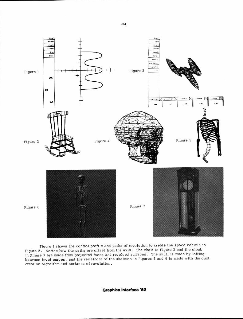
Figure 1 shows the control profile and paths of revolution to create the space vehicle in Figure 2. Notice how the pa ths are offset from the axis. The chair in Figure 3 and the clock in Figure 7 are made from projected faces and revolved surfaces. The skull is made by lofting between level curves, and the remainder of the skeleton in Figures 5 and 6 is made with the duc t creation algorithm and surfaces of revolution.
Graphics Interface '82