graphical interface generator user's guide - libglass -...
TRANSCRIPT
Graphical Interface Generator User's Guide
Glass Tool
Marcelo de Paiva Guimarães [email protected] Bruno Barberi Gnecco [email protected]
17th July 2004

4
GEditor © 2003, 2004 Marcelo de Paiva Guimarães and Bruno Barberi Gnecco <paiva, [email protected]>

5
Contents 1. Introduction.............................................................................................................. 6
1.1 License ............................................................................................................... 7
1.2 Requirements...................................................................................................... 7
1.3 Tools................................................................................................................... 7
1.3 Portability........................................................................................................... 7
1.4 Where to get ....................................................................................................... 8
1.5 Install.................................................................................................................. 8
1.6 Examples ............................................................................................................ 8
1.7 Acknowledgements ............................................................................................ 9
2. Graphical Interface Generator................................................................................ 10
2.1 GEditor............................................................................................................. 10
2.1 GPda................................................................................................................. 12
3. Step-by-step ........................................................................................................... 14
3.1 GEditor Interface.............................................................................................. 14
3.2 GEditor project................................................................................................. 18
3.3 Receiving the events in the cluster................................................................... 31
3.4 GPda................................................................................................................. 32
Chapter 1 - Introduction
6
Chapter 1
1. INTRODUCTION
Input devices are used in Virtual Reality (VR) to let the user interact with the
virtual world, providing the feeling of immersion in the environment. Traditionally,
VR applications have used specialized devices (gloves, 3-D joysticks and HMD) that
are often produced for a relatively small niche market, are extremely expensive,
subject to several limitations, such as freedom of movement, and are not easily
mastered by inexperienced users.
The integration with PDA (Personal Digital Assistant) devices brings several
advantages to VR. Most common PDAs are portable, lightweight and enhanced with
fast processors, RAM and ROM capabilities, supporting complex tasks such as the
visualization of multimedia data (images, texts, voice, sounds, video/audio
streaming), etc. Moreover, they are compatible with wireless standard IEEE 802.11
and with other interfaces, like GPRS, Bluetooth, Serial and Infra-red.Thanks to these
features, PDAs are being used in VR applications, not only to provide a friendly,
active participation to the virtual experience, but also to visualize and insert
multimedia data and comments both during the virtual experience and after it.
The GEditor simplify the design of graphical interfaces and their interaction
with the VR application, freeing the designer from having to know all the details of
the individual technologies, and to use PDAs as interaction device. The interfaces
generated are simple and intuitive, and can be used even by untrained users to
interact with a distributed virtual environment. This solution requires no
programming knowledge from the GUI designer. The PDA application
communicates transparently with a cluster, via any underlying network system,
which processes the events and maintains the synchrony of the rendered images in
real-time. Moreover, the interface and its configuration can be changed at run-time.
This solution is part of Glass, a library for the development of distributed
applications. It offers key features for distributed VR applications, such as data lock
and frame lock synchronization (see Glass manual to details about it).
Chapter 1 - Introduction
7
1.1 License
GEditor is released under the LGPL License (see
http://www.gnu.org/licenses/lgpl.html for details).
1.2 Requirements
• GEditor should work with any Java compiler.
• It´s provided with Glass.
• Linux and Java Virtual Machine are required for the PDA applications test.
• Compile the Glass for the PDA (using the appropriated compiler)
1.3 Tools
• geditor allows the development of the interface which will run on the PDA.
• gpda executes the application, developed on the geditor, on the PDA.
1.3 Portability
GEditor was developed in a Linux/x86 platform, which is what most of the
clusters run, anyway. It should run in any Unix that full the requirements
• GEditor was tested on the following architecture:
- Linux 2.4/x86
- Windows
• GPpda was tested on the following architecture with the iPAQ H3970:
- Linux 2.4 (see www.handhelds.org to details)
- Windows
GPda should run in any architecture supported by the Glass library and by
Java.
Chapter 1 - Introduction
8
1.4 Where to get
GEditor/GPda official homepage is:
• http://libglass.sourceforge.net/
• http://www.lsi.usp.br/~paiva/glass/
• http://www.lsi.usp.br/~brunobg/glass/
You can contact the authors:
Marcelo de Paiva Guimarães [email protected]
Bruno Barberi Gnecco [email protected]
1.5 Install
First install the Glass library (see it´s manual to details).
In the glass glass/utils/geditor/src/ subdirectory execute
Make
You'll find in glass/utils/geditor/bin/ directory the geditor.jar
and gpda.jar.
To run the geditor execute
java –jar geditor.jar
To run the gpda execute
java –jar gpda.jar Projectname.glass host
1.6 Examples
In the glass/utils/geditor/projects/ subdirectory you will find
some examples. They are a good source for learning the geditor, and some of them
are used in this guide to illustrate examples.
You'll find in that directory a README with descriptions of each program.
Chapter 1 - Introduction
9
1.7 Acknowledgements
Thanks to Hilton Fernandes for provide the PDA´s for the tests and the valuable
technical support.

Chapter 2 – Graphical Interface Generator
10
Chapter 2
2. GRAPHICAL INTERFACE GENERATOR
2.1 GEditor
The graphical interface generator tool consists of a Java application. Java was
chosen due to its platform independence. The tool proposes a simple approach to
GUIs. Instead of the usual set of widgets present in most GUI APIs, an image is
used. The designer then defines hot spot areas on this image, which can be associated
to events of the application. A complex GUI, with alphanumeric fields, menus, etc.,
reduces the feeling of immersion, since the user has to concentrate on the device
instead of on the application.
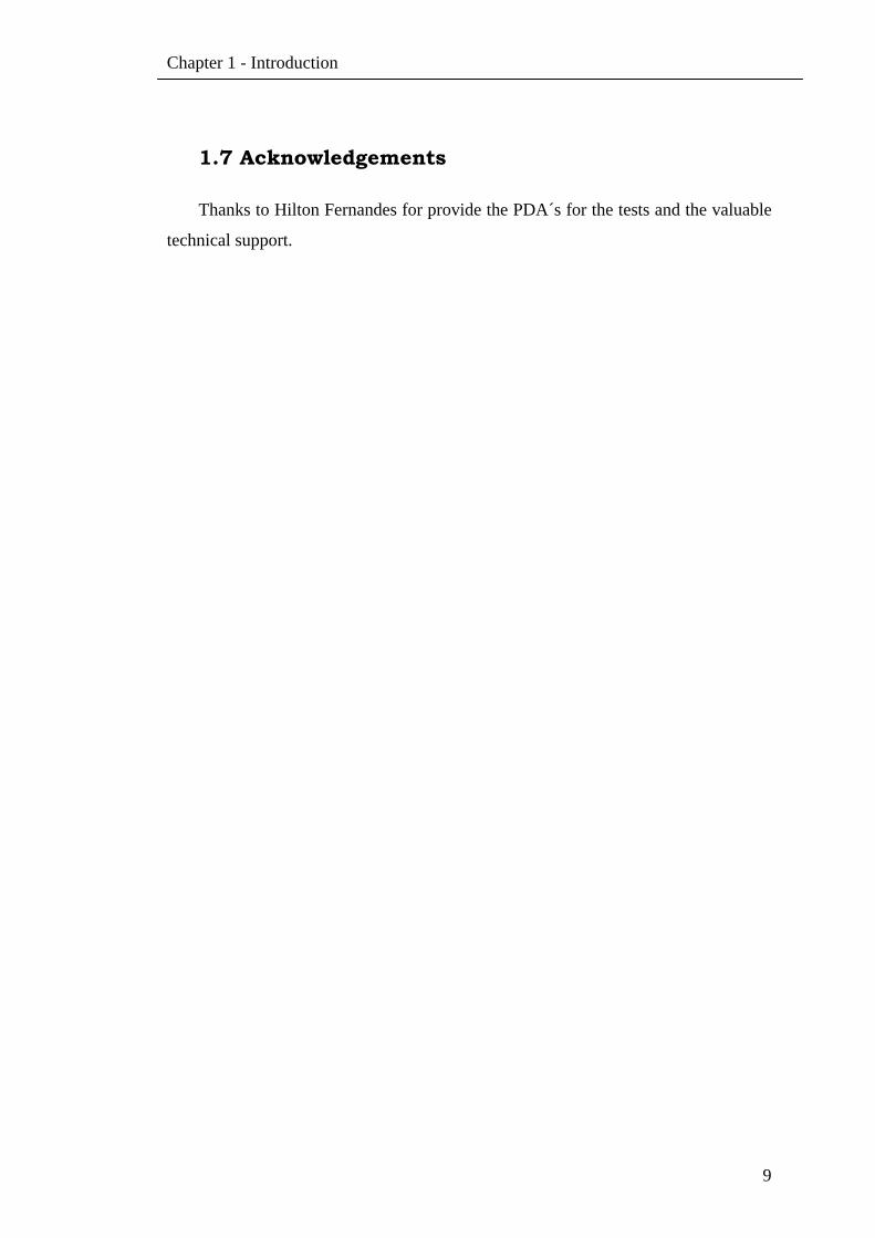
A screenshot of the tool is shown on Figure 1. One can see on the center the GUI
image, which will be shown on the PDA, and the colored hot spots over it. On the
right there is a list of the hot spots and the events that are associated with them. The
designer uses the buttons on the toolbar to select, add and erase the hot spots. The hot
spots can be either a rectangle or an ellipse, and hot spots associated with the same
events can overlap. The menus supply resources to create, close, and save the project,
and to resize the image area. Image size area present on the Figure 1 is configured to
an iPAQ H3970 (240 x 320).
Chapter 2 – Graphical Interface Generator
11
Figure 1 – GUI design tool, showing the Celestia interface.
Each hot spot is associated to an event, which has a number (automatically
generated), name, color and type. One event can have more than one hot spot
mapped. There are three types of events:
• Simple event: when triggered, the associated event number is sent to the
interested nodes, which will process it.
• Exit event: when triggered, the application running on PDA exits, notifying
the other nodes.
• Skin event: when triggered, the PDA skin (background image) is changed. An
application may have a set of skins, and each skin may have a different set of
hot spots. These events are attended locally, but a notification may be
propagated to other nodes.
• Position event: when triggered, the position of the PDA interface clicked (x,y)
is sent to the interested nodes, which will process it.
The decision of treating events remotely simplifies the development of the GUI.
It’s also easier to change the GUI, since it requires no change or recompilation of the
application. The GUI designers don’t need any programming knowledge.
Chapter 2 – Graphical Interface Generator
12
2.1 GPda
The graphical interface generator tool creates a data file to be used with the GUI
Java application. A skeleton of the event handler on the main application is also
generated automatically (in C). This routine will receive the events from the PDA on
the main application and process them.
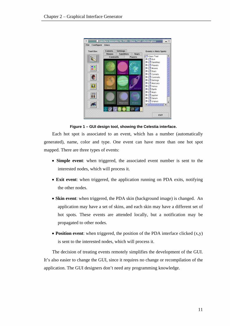
Figure 2 presents a skeleton example. This code can be used as initial base to
implement the event handler. When the user clicks on the hot spot “Mercury”, for
example, this routine will receive the associated value and the switch will handle it.
Figure 2 – Skeleton code of the event handler.
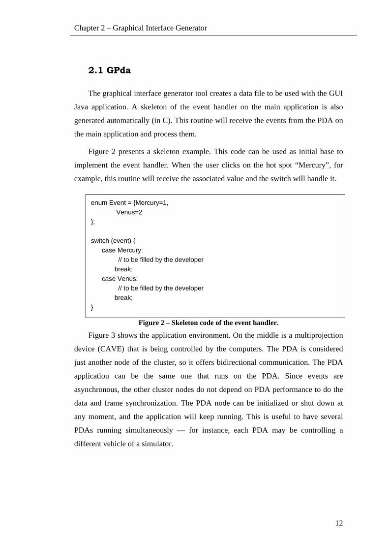
Figure 3 shows the application environment. On the middle is a multiprojection
device (CAVE) that is being controlled by the computers. The PDA is considered
just another node of the cluster, so it offers bidirectional communication. The PDA
application can be the same one that runs on the PDA. Since events are
asynchronous, the other cluster nodes do not depend on PDA performance to do the
data and frame synchronization. The PDA node can be initialized or shut down at
any moment, and the application will keep running. This is useful to have several
PDAs running simultaneously — for instance, each PDA may be controlling a
different vehicle of a simulator.
enum Event = {Mercury=1, Venus=2 }; switch (event) { case Mercury: // to be filled by the developer break; case Venus: // to be filled by the developer break; }
Chapter 2 – Graphical Interface Generator
13
Figure 3 – The PDA is a cluster node.
The PDA application uses the Swing Java component. The use of Java allows
the application to be executed on many different operational systems (Windows,
Linux, Windows CE, IRIX) and platforms.
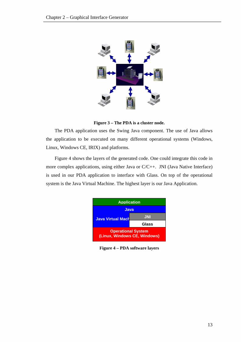
Figure 4 shows the layers of the generated code. One could integrate this code in
more complex applications, using either Java or C/C++. JNI (Java Native Interface)
is used in our PDA application to interface with Glass. On top of the operational
system is the Java Virtual Machine. The highest layer is our Java Application.
Figure 4 – PDA software layers
Application
Java
Java Virtual Machine JNI
GlassOperational System
(Linux, Windows CE, Windows)
Step-by-step
14
Chapter 3
3. STEP-BY-STEP
This step-by-step chapter provides instructions of how to use the GEditor. It
guides you through the process of create a new interface for PDAs and the run
process on the PDA.
3.1 GEditor Interface
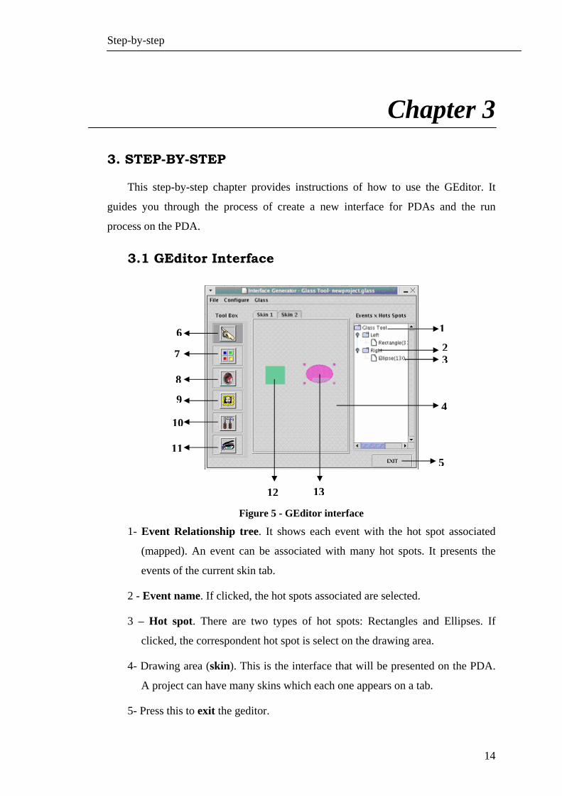
Figure 5 - GEditor interface
1- Event Relationship tree. It shows each event with the hot spot associated
(mapped). An event can be associated with many hot spots. It presents the
events of the current skin tab.
2 - Event name. If clicked, the hot spots associated are selected.
3 – Hot spot. There are two types of hot spots: Rectangles and Ellipses. If
clicked, the correspondent hot spot is select on the drawing area.
4- Drawing area (skin). This is the interface that will be presented on the PDA.
A project can have many skins which each one appears on a tab.
5- Press this to exit the geditor.
6
7
8
9
10
11
12 13
5
1
23
4
Step-by-step
15
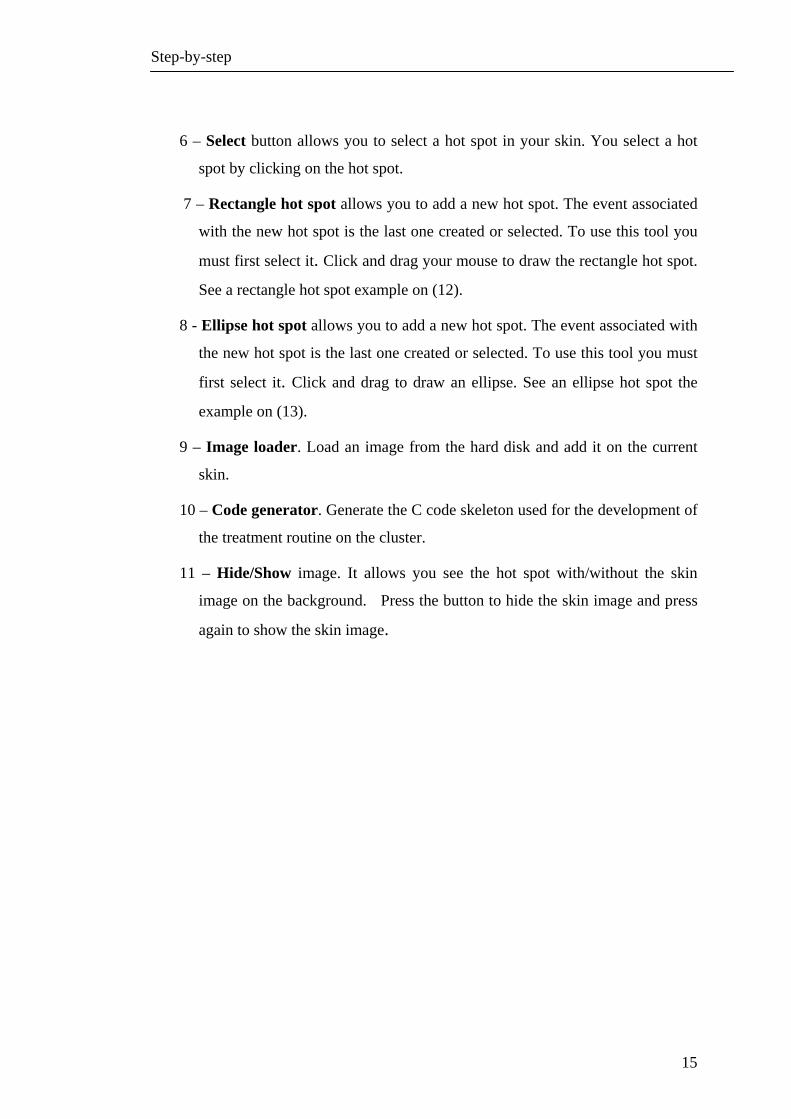
6 – Select button allows you to select a hot spot in your skin. You select a hot
spot by clicking on the hot spot.
7 – Rectangle hot spot allows you to add a new hot spot. The event associated
with the new hot spot is the last one created or selected. To use this tool you
must first select it. Click and drag your mouse to draw the rectangle hot spot.
See a rectangle hot spot example on (12).
8 - Ellipse hot spot allows you to add a new hot spot. The event associated with
the new hot spot is the last one created or selected. To use this tool you must
first select it. Click and drag to draw an ellipse. See an ellipse hot spot the
example on (13).
9 – Image loader. Load an image from the hard disk and add it on the current
skin.
10 – Code generator. Generate the C code skeleton used for the development of
the treatment routine on the cluster.
11 – Hide/Show image. It allows you see the hot spot with/without the skin
image on the background. Press the button to hide the skin image and press
again to show the skin image.

Step-by-step
16
Figure 6 – Geditor interface
1 – File menu.
• New- create a new project.
• Open – open a existing project
• Save – save the project
• Close – close the project
2 – Configure menu. It allows you to set the skin image area. Each PDA has the
own image area (height and weight).
3 – Glass menu. It shows the about dialog.
4 – Tab. A project can have many skins. Each skins is presented on a tab. To
change to another skin, press the tab.
5 – Example of Skin image loaded.
6 – Menu allows you manipulate the events, hot spots or the skins. If a hot spot
is not select, the hot spot options are not enabled.
7 – Events allows you to add a new event or change its name and/or color.
8 – Hot Spot Association allows you to associate the current hot spot selected
with an event. This option is enabled on the Menu if a hot spot is selected.
1 2 3
4
5
68
910 11
12 13
14 15
7
Step-by-step
17
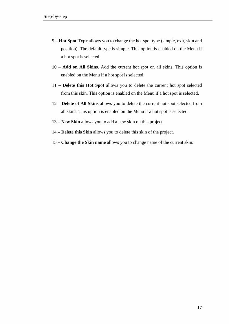
9 – Hot Spot Type allows you to change the hot spot type (simple, exit, skin and
position). The default type is simple. This option is enabled on the Menu if
a hot spot is selected.
10 – Add on All Skins. Add the current hot spot on all skins. This option is
enabled on the Menu if a hot spot is selected.
11 – Delete this Hot Spot allows you to delete the current hot spot selected
from this skin. This option is enabled on the Menu if a hot spot is selected.
12 – Delete of All Skins allows you to delete the current hot spot selected from
all skins. This option is enabled on the Menu if a hot spot is selected.
13 – New Skin allows you to add a new skin on this project
14 – Delete this Skin allows you to delete this skin of the project.
15 – Change the Skin name allows you to change name of the current skin.
Step-by-step
18
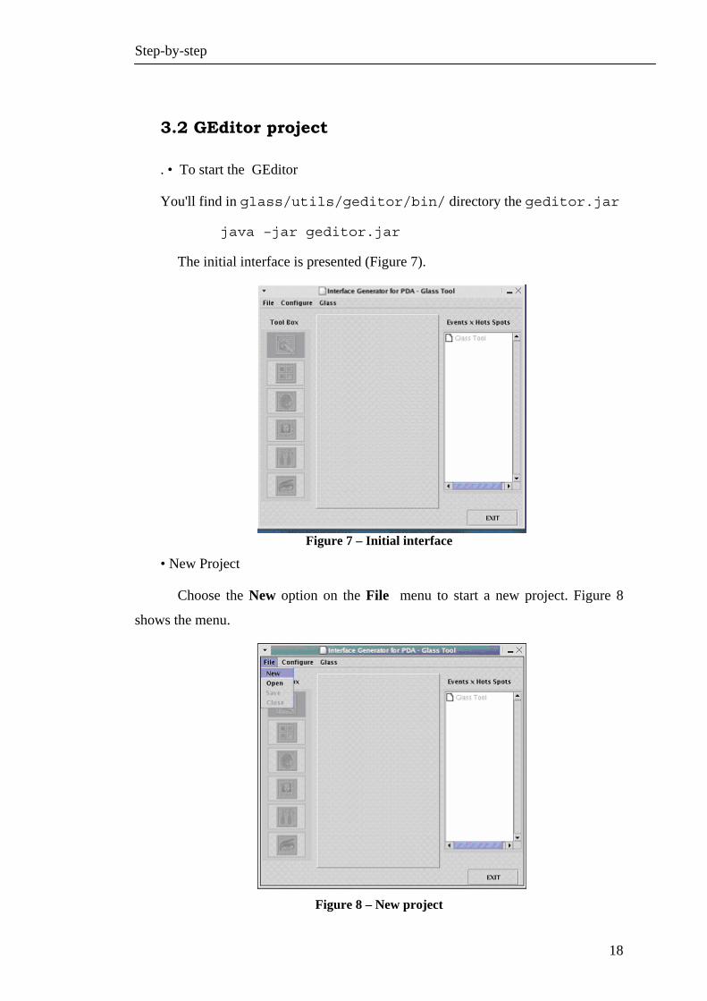
3.2 GEditor project
. • To start the GEditor
You'll find in glass/utils/geditor/bin/ directory the geditor.jar
java –jar geditor.jar
The initial interface is presented (Figure 7).
Figure 7 – Initial interface
• New Project
Choose the New option on the File menu to start a new project. Figure 8
shows the menu.
Figure 8 – New project

Step-by-step
19
• Project name
Type the project name in the dialog box (Figure 9).
Figure 9 – Project name
• Adding a image on the current skin
Press Image loader button to load the image for this skin (Figure 10).
Figure 10 – Loading an image

Step-by-step
20
• Choosing the image
You must use the Chosen box presented on Figure 11 to select an image.
Figure 11 – Choosing an image
• New skin image
Figure 12 presents the image added on the current skin.
Figure 12 – Skin image
Step-by-step
21
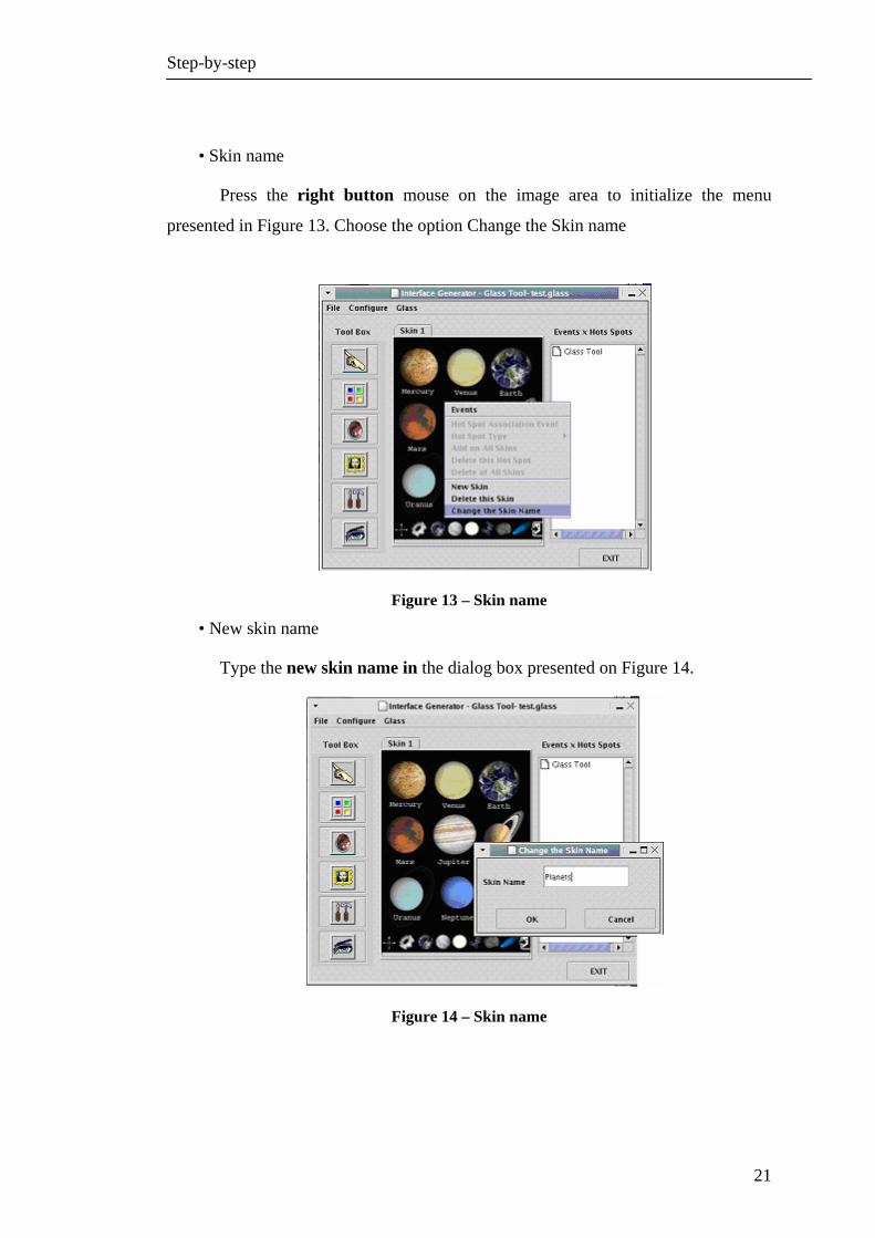
• Skin name
Press the right button mouse on the image area to initialize the menu
presented in Figure 13. Choose the option Change the Skin name
Figure 13 – Skin name
• New skin name
Type the new skin name in the dialog box presented on Figure 14.
Figure 14 – Skin name
Step-by-step
22
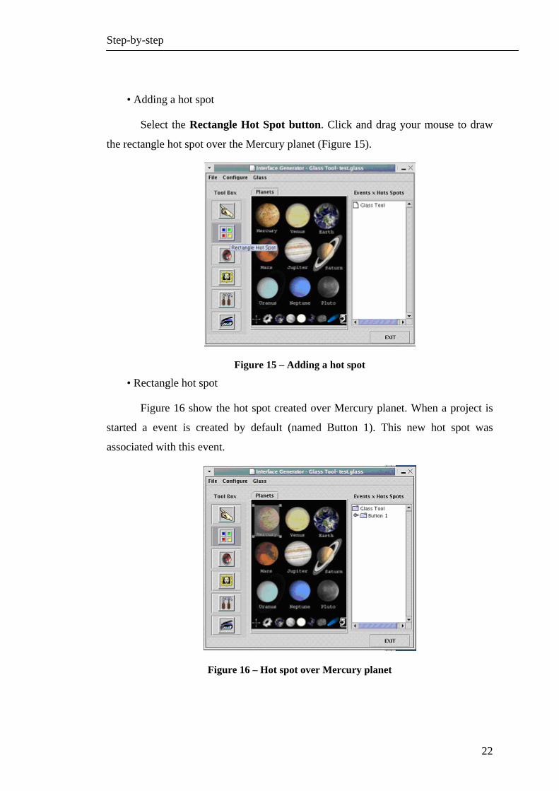
• Adding a hot spot
Select the Rectangle Hot Spot button. Click and drag your mouse to draw
the rectangle hot spot over the Mercury planet (Figure 15).
Figure 15 – Adding a hot spot
• Rectangle hot spot
Figure 16 show the hot spot created over Mercury planet. When a project is
started a event is created by default (named Button 1). This new hot spot was
associated with this event.
Figure 16 – Hot spot over Mercury planet

Step-by-step
23
• Changing attribute of a event
This first event was created by default. To change its values click right
mouse button to appear the Menu presented on Figure 17 . Choose the option
Events.
Figure 17 – Event values
• Changing hot spot values
Type the new name for this event (Mercury). If the color is similar to the
image in skin, you can change it pressing the button Color (Figure 18).
Figure 18 – Changing event values

Step-by-step
24
• Creating another event
Press the right button mouse on the image area and choose the Events
option. Press New button to create a new event (Figure 19).
Figure 19 – Creating an event
• The new event
Type the event Name (Venus). The event color is generated automatically; it
is up to you to change it. Press Color button to choose another color to this event.
(Figure 20)
Figure 20 – New event

Step-by-step
25
• Ellipse hot spot
The current event is the Event Venus (number 2). Press Ellipse Hot Spot
button and draw a hot spot over the Venus planet (Figure 21).
Figure 21 – Ellipse hot spot
• Ellipse hot spot
Figure 22 shows the hot spot created over the Venus planet.
Figure 22 – Vênus hot spot

Step-by-step
26
• Adding a skin
Click right button mouse and select New Skin option (Figure 23).
Figure 23 – Adding a skin
• Loading a image for the new skin
Select the new Tab and press the Image loader button to load the image.
You must use the Chosen dialog to select an image (Figure 24).
Figure 24 –Loading a image

Step-by-step
27
• Skin name
Press the right button mouse on the image area to initialize the menu and select
the option Change the Skin name. Type the skin name (Figure 25).
Figure 25 – Skin name
• Skin
Figure 26 shows the project with two skins.
Figure 26 – Two skins
Step-by-step
28
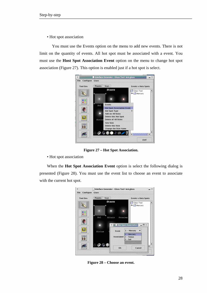
• Hot spot association
You must use the Events option on the menu to add new events. There is not
limit on the quantity of events. All hot spot must be associated with a event. You
must use the Host Spot Association Event option on the menu to change hot spot
association (Figure 27). This option is enabled just if a hot spot is select.
Figure 27 – Hot Spot Association.
• Hot spot association
When the Hot Spot Association Event option is select the following dialog is
presented (Figure 28). You must use the event list to choose an event to associate
with the current hot spot.
Figure 28 – Choose an event.

Step-by-step
29
• Hot spot type
On the button corner of this skin there is exit hot spot. The difference between
this hot spot and other created before is the type. You must select the hot spot, click
the right mouse button, choose the option Hot Spot Type and select the Hot Spot
Type. This example shows an Exit button, so you must select the exit option (Figure
29)
Figure 29 – Hot Spot Type

Step-by-step
30
• Code generation process
Press Code generator button to create the C code skeleton (Figure 30).
Figure 30 – Code Genaration
• Code generation dialog
Figure 31 shows the dialog box asking for the file name.
Figure 31 – Code Generation

Step-by-step
31
• Save the project
Click File-> Save to save the project. Figure 32 shows the dialog box asking for
the project destination.
Figure 32 – Saving the project
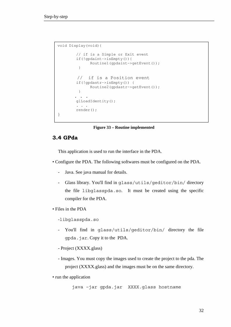
3.3 Receiving the events in the cluster
The cluster application will receives the events form the PDA and process them.
You must use the variable gpdaint to receive Simple and Exit events, and you must
use the variable gpdastr to receive Position event. The event returned in gpdastr
variable is a string which the first part is x position and the second part is y position.
The position are separated by “;”. For example: “3;6”
Figure 33 presents a receiving routine implemented. When gpdaint is not empty
the Routine1 is called. When gpdastr is not empty the Routine2 is called. These
routes must interpret the arguments and execute the appropriated commands.
Step-by-step
32
Figure 33 – Routine implemented
3.4 GPda
This application is used to run the interface in the PDA.
• Configure the PDA. The following softwares must be configured on the PDA.
- Java. See java manual for details.
- Glass library. You'll find in glass/utils/geditor/bin/ directory
the file libglasspda.so. It must be created using the specific
compiler for the PDA.
• Files in the PDA
-libglasspda.so
- You'll find in glass/utils/geditor/bin/ directory the file
gpda.jar. Copy it to the PDA.
- Project (XXXX.glass)
- Images. You must copy the images used to create the project to the pda. The
project (XXXX.glass) and the images must be on the same directory.
• run the application
java –jar gpda.jar XXXX.glass hostname
void Display(void){ // if is a Simple or Exit event if(!gpdaint->isEmpty()){ Routine1(gpdaint->getEvent()); } // if is a Position event if(!gpdastr->isEmpty()) { Routine2(gpdastr->getEvent()); } . . . glLoadIdentity(); . . . render(); }