8360 b-series swept signal generator user's...
TRANSCRIPT

Serial Number Prefixes:
Agilent Technologies8360 B-Series Swept Signal Generator
(Including Options 001, 002, 004, 006, and 008)
User’s Guide
Part No. 08360-90127
Printed in USAMay 2001
Supersedes March 2001
.
This manual applies directly to any swept signal generator with themodel and serial number prefix combination shown below. You mayhave to modfiy this manual so that it applies directly to yourinstrument version. Refer to the “Instrument History” chapter.
Agilent Technologies 83620B/22B/23B/24B/30B3844A and Below
Agilent Technologies 83640B/50B3844A and Below

Notice The information contained in this document is subject to changewithout notice.
Agilent Technologies makes no warranty of any kind with regard tothis material, including but not limited to, the implied warrantiesof merchantability and �tness for a particular purpose. AgilentTechnologies shall not be liable for errors contained herein orfor incidental or consequential damages in connection with thefurnishing, performance, or use of this material.
Restricted RightsLegend
Use, duplication, or disclosure by the U.S. Government is subjectto restrictions as set forth in subparagraph (c) (1) (ii) of theRights of Technical Data and Computer Software clause at DFARS252.227-7013 for DOD agencies, and subparagraphs (c) (1) and(c) (2) of the Commercial Computer Software Restricted Rightsclause at FAR 52.227-19 for other agencies.
c Copyright Agilent Technologies 1996, 1997, 1999, 2000, 2001All Rights Reserved. Reproduction, adaptation, or translationwithout prior written permission is prohibited, except as allowedunder the copyright laws.1400 Fountaingrove Parkway, Santa Rosa, CA 95403-1799, USA

Certification Agilent Technologies certi�es that this product met its publishedspeci�cations at the time of shipment from the factory. AgilentTechnologies further certi�es that its calibration measurements aretraceable to the United States National Institute of Standards andTechnology, to the extent allowed by the Institute's calibrationfacility, and to the calibration facilities of other InternationalStandards Organization members.
Warranty This Agilent Technologies instrument product is warranted againstdefects in material and workmanship for a period of one year fromdate of shipment. During the warranty period, Agilent Technologieswill, at its option, either repair or replace products which prove to bedefective.
For warranty service or repair, this product must be returnedto a service facility designated by Agilent Technologies. Buyershall prepay shipping charges to Agilent Technologies and AgilentTechnologies shall pay shipping charges to return the product toBuyer. However, Buyer shall pay all shipping charges, duties, andtaxes for products returned to Agilent Technologies from anothercountry.
Agilent Technologies warrants that its software and �rmwaredesignated by Agilent Technologies for use with an instrument willexecute its programming instructions when properly installed on thatinstrument. Agilent Technologies does not warrant that the operationof the instrument, or software, or �rmware will be uninterrupted orerror-free.
Limitation of Warranty
The foregoing warranty shall not apply to defects resulting fromimproper or inadequate maintenance by Buyer, Buyer-suppliedsoftware or interfacing, unauthorized modi�cation or misuse,operation outside of the environmental speci�cations for theproduct, or improper site preparation or maintenance.
NO OTHER WARRANTY IS EXPRESSED OR IMPLIED.AGILENT TECHNOLOGIES SPECIFICALLY DISCLAIMSTHE IMPLIED WARRANTIES OF MERCHANTABILITY ANDFITNESS FOR A PARTICULAR PURPOSE.
Exclusive Remedies
THE REMEDIES PROVIDED HEREIN ARE BUYER'S SOLEAND EXCLUSIVE REMEDIES. HEWLETT-PACKARD SHALLNOT BE LIABLE FOR ANY DIRECT, INDIRECT, SPECIAL,INCIDENTAL, OR CONSEQUENTIAL DAMAGES, WHETHERBASED ON CONTRACT, TORT, OR ANY OTHER LEGALTHEORY.
iii

Assistance Product maintenance agreements and other customer assistanceagreements are available for Agilent Technologies products. Forany assistance, contact your nearest Agilent Technologies Sales andService O�ce.
Safety Notes The following safety notes are used throughout this manual.Familiarize yourself with each of the notes and its meaning beforeoperating this instrument.
WARNING Warning denotes a hazard. It calls attention to a procedure which, if
not correctly performed or adhered to, could result in injury or loss
of life. Do not proceed beyond a warning note until the indicated
conditions are fully understood and met.
CAUTION Caution denotes a hazard. It calls attention to a procedure that, ifnot correctly performed or adhered to, would result in damage to ordestruction of the instrument. Do not proceed beyond a caution signuntil the indicated conditions are fully understood and met.
iv
General SafetyConsiderations
WARNING No operator serviceable parts inside. Refer servicing to qualified
personnel. To prevent electrical shock, do not remove covers.
For continued protection against fire hazard replace line fuse only
with same type and rating (F 5A/250V). The use of other fuses or
material is prohibited.
This is a Safety Class I product (provided with a protective earthing
ground incorporated in the power cord). The mains plug shall only
be inserted in a socket outlet provided with a protective earth
contact. Any interruption of the protective conductor, inside or
outside the instrument, is likely to make the instrument dangerous.
Intentional interruption is prohibited.
If this instrument is used in a manner not specified by Agilent
Technologies, the protection provided by the instrument may be
impaired. This product must be used in a normal condition (in which
all means for protection are intact) only.
Position the instrument according to the enclosure protection
provided. This instrument does not protect against the ingress of
water. This instrument protects against finger access to hazardous
parts within the enclosure.
v

CAUTION Before switching on this instrument, make sure that the linevoltage selector switch is set to the voltage of the power supply andthe correct fuse is installed.
Always use the three-prong ac power cord supplied with thisinstrument. Failure to ensure adequate earth grounding by notusing this cord may cause instrument damage.
Before switching on this product, make sure that the line voltageselector switch is set to the voltage of the power supply andthe correct fuse is installed. Assure the supply voltage is in thespeci�ed range.
Ventilation Requirements: When installing the instrument in acabinet, the convection into and out of the instrument must not berestricted. The ambient temperature (outside the cabinet) must beless than the maximum operating temperature of the instrumentby 4 �C for every 100 watts dissipated in the cabinet. If the totalpower dissipated in the cabinet is greater than 800 watts, thenforced convection must be used.
This product is designed for use in Installation Category II andPollution Degree 2 per IEC 1010 and 664, respectively.
Note The detachable power cord is the instrument disconnecting device.It disconnects the mains circuits from the mains supply before otherparts of the instrument. The front panel switch is only a standbyswitch and is not a LINE switch.
vi

PREFACE This manual provides user information for the Agilent Technologies8360 B-Series swept signal generator.
Instruments CoveredBy This Manual
This manual applies to instruments having a serial number pre�xlisted on the title page (behind the \Documentation Map" tab).Some changes may have to be made to this manual so that itapplies directly to each instrument; refer to Chapter 5, \InstrumentHistory", to see what changes may apply to your instrument.
A serial number label (Figure 0-1) is attached to the instrument'srear panel. A pre�x (four digits followed by a letter), and a su�x(�ve digits unique to each instrument), comprise the instrumentserial number.
Figure 0-1.
Typical Serial Number Label
User's GuideOrganization
Tabs divide the major chapters of this manual. The contents of eachchapter is listed in the Table of Contents.
AgilentTechnologies 8360B-SeriesDocumentation
Documentation Map
For a pictorial representation of the Agilent Technologies8360 B-Series documentation, see the \Documentation Map" at thefront of this manual.
Ordering Manuals
A manual part number is listed on the title page of this manual. Youmay use it to order extra copies of this manual. See \ReplaceableParts" in Agilent Technologies 8360 B-Series Swept SignalGenerator/8360 L-Series Swept CW Generator Service Guide fora complete list of Agilent Technologies 8360 documentation andordering numbers.
vii

TypefaceConventions
The following conventions are used in the Agilent Technologies8360 B-Series documentation:
Italics Italic type is used for emphasis, and for titles of manuals andother publications.
Computer Computer type is used for information displayed on theinstrument. For example: In this sequence, POWER LEVEL is displayed.
�Hardkeys� Instrument keys are represented in \key cap." You areinstructed to press a hardkey.NNNNNNNNNNNNNNNNNNNNNNNNNNSoftkeys Softkeys are located just below the display, and theirfunctions depend on the current display. These keys are representedin \softkey." You are instructed to select a softkey.
RegulatoryInformation
This product has been designed and tested in accordance with IECPublication 1010, Safety Requirements for Electronic MeasuringApparatus, and has been supplied in a safe condition. Theinstruction documentation contains information and warningswhich must be followed by the user to ensure safe operation and tomaintain the instrument in a safe condition.
viii

Manufacturer'sDeclaration
Note This is to certify that this product meets the radio frequencyinterference requirements of Directive FTZ 1046/1984. The GermanBundespost has been noti�ed that this equipment was put intocirculation and has been granted the right to check the product typefor compliance with these requirements.
Note: If test and measurement equipment is operated withunshielded cables and/or used for measurements on open set-ups, theuser must insure that under these operating conditions, the radiofrequency interference limits are met at the border of his premises.
Model Agilent Technologies 8360 B-Series swept signal generator
Note Hiermit wird bescheinigt, dass dieses Ger�at/System in�Ubereinstimmung mit den Bestimmungen von Postverf�ugung 1046/84funkentst"rt ist.
Der Deutschen Bundespost wurde das Inverkehrbringen diesesGer�ates/Systems angezeight und die Berechtigung zur �Uberpr�ufungder Serie auf Einhaltung der Bestimmungen einger�aumt.
Zustzinformation f�ur Mess-und Testger�ate:
Werden Mess- und Testger�ate mit ungeschirmten Kabeln und/oderin o�enen Messaufbauten verwendet, so ist vom Betreibersicherzustellen, dass die Funk-Entst"rbestimmungen unterBetriebsbedingungen an seiner Grundst�ucksgrenze eingehaltenwerden.
ix

Declaration ofConformity
x

Compliance withGerman NoiseRequirements
This is to declare that this instrument is in conformance with theGerman Regulation on Noise Declaration for Machines (Laermangabenach der Maschinenlaermrerordnung �3.GSGV Deutschland).
Acoustic Noise Emission/Geraeuschemission
LpA <70 dB LpA <70 dB
Operator position am Arbeitsplatz
Normal position normaler Betrieb
per ISO 7779 nach DIN 45635 t.19
Instrument Markings L The instruction documentation symbol. The product ismarked with this symbol when it is necessary for theuser to refer to the instructions in the documentation.
The CE mark is a registered trademark of the EuropeanCommunity.
The CSA mark is a registered trademark of theCanadian Standards Association.
\ISM1-A" This is a symbol of an Industrial Scienti�c and MedicalGroup 1 Class A product.
This is an ON symbol. The symbol ON is used to markthe position of the instrument power line switch.
This is an ON symbol. The symbol ON is used to markthe position of the instrument power line switch.
This is a STANDBY symbol. The STANDBY symbol isused to mark the position of the instrument power lineswitch.
This is an OFF symbol. The OFF symbol is used tomark the position of the instrument power line switch.
This is an AC symbol. The AC symbol is used toindicate the required nature of the line module inputpower.
xi

Table 0-1. Agilent Technologies Sales and Service Offices
UNITED STATES
Instrument Support CenterAgilent Technologies(800) 403-0801
EUROPEAN FIELD OPERATIONS
Headquarters France Germany
Agilent Technologies S.A. Agilent Technologies France Agilent Technologies GmbH150, Route du Nant-d'Avril 1 Avenue Du Canada Agilent Technologies Strasse1217 Meyrin 2/Geneva Zone D'Activite De Courtaboeuf 61352 Bad Homburg v.d.HSwitzerland F-91947 Les Ulis Cedex Germany(41 22) 780.8111 France (49 6172) 16-0
(33 1) 69 82 60 60Great Britain
Agilent Technologies Ltd.Eskdale Road, Winnersh TriangleWokingham, Berkshire RG41 5DZEngland(44 118) 9696622
INTERCON FIELD OPERATIONS
Headquarters Australia Canada
Agilent Technologies Agilent Technologies Australia Ltd. Agilent Technologies (Canada) Ltd.3495 Deer Creek Road 31-41 Joseph Street 17500 South Service RoadPalo Alto, California, USA Blackburn, Victoria 3130 Trans-Canada Highway94304-1316 (61 3) 895-2895 Kirkland, Quebec H9J 2X8(650) 857-5027 Canada
(514) 697-4232
China Japan Singapore
China Agilent Technologies Agilent Technologies Japan, Ltd. Agilent Technologies Singapore (Pte.) Ltd.38 Bei San Huan X1 Road 9-1 Takakura-Cho, Hachioji 150 Beach RoadShuang Yu Shu Tokyo 192, Japan #29-00 Gateway WestHai Dian District (81 426) 60-2111 Singapore 0718Beijing, China (65) 291-9088(86 1) 256-6888
Taiwan
Agilent Technologies Taiwan8th Floor, H-P Building337 Fu Hsing North RoadTaipei, Taiwan(886 2) 712-0404
xii
Contents
1. Getting StartedWhat Is In This Chapter . . . . . . . . . . . . 1-1How To Use This Chapter . . . . . . . . . . . . 1-2Equipment Used In Examples . . . . . . . . . 1-2
Introducing the Agilent 8360 B-Series Swept SignalGenerators . . . . . . . . . . . . . . . . . 1-3
Display Area . . . . . . . . . . . . . . . . . . 1-4Entry Area . . . . . . . . . . . . . . . . . . 1-5CW Operation and Start/Stop Frequency Sweep . . 1-6CW Operation . . . . . . . . . . . . . . . . 1-6Start/Stop Frequency Sweep . . . . . . . . . . 1-6
Center Frequency/Span Operation . . . . . . . . 1-8Power Level and Sweep Time Operation . . . . . . 1-10Power Level Operation . . . . . . . . . . . . 1-10Sweep Time Operation . . . . . . . . . . . . 1-10
Continuous, Single, and Manual Sweep Operation . 1-12Marker Operation . . . . . . . . . . . . . . . 1-14Saving and Recalling an Instrument State . . . . . 1-16Power Sweep and Power Slope Operation . . . . . 1-18Power Sweep Operation . . . . . . . . . . . . 1-18Power Slope Operation . . . . . . . . . . . . 1-19
Getting Started Advanced . . . . . . . . . . . . 1-21Externally Leveling the Swept Signal Generator . . 1-23Leveling with Detectors/Couplers /Splitters . . . 1-23External Leveling Used With the Optional Step
Attenuator . . . . . . . . . . . . . . . 1-26Leveling with Power Meters . . . . . . . . . . 1-27Leveling with MM-wave Source Modules . . . . . 1-28
Working with Mixers/Reverse Power E�ects . . . . 1-30Working with Spectrum Analyzers/Reverse Power
E�ects . . . . . . . . . . . . . . . . . . . 1-32Optimizing Swept Signal Generator Performance . . 1-33Creating and Applying the User Flatness Correction
Array . . . . . . . . . . . . . . . . . . 1-33Creating a User Flatness Array Automatically,
Example 1 . . . . . . . . . . . . . . . 1-34Creating a User Flatness Array, Example 2 . . 1-36Swept mm-wave Measurement with Arbitrary
Correction Frequencies, Example 3 . . . . 1-39Scalar Analysis Measurement with User Flatness
Corrections, Example 4 . . . . . . . . . 1-43Using Detector Calibration . . . . . . . . . . 1-47
Contents-1

Using the Tracking Feature . . . . . . . . . . 1-49Peaking . . . . . . . . . . . . . . . . . . 1-49Tracking . . . . . . . . . . . . . . . . . 1-49
ALC Bandwidth Selection . . . . . . . . . . . . 1-50Using Step Sweep . . . . . . . . . . . . . . . 1-51Creating and Using a Frequency List . . . . . . . 1-52Using the Security Features . . . . . . . . . . . 1-53Changing the Preset Parameters . . . . . . . . . 1-54Getting Started Programming . . . . . . . . . . 1-55GPIB General Information . . . . . . . . . . . 1-56Interconnecting Cables . . . . . . . . . . . . 1-56Instrument Addresses . . . . . . . . . . . . . 1-56GPIB Instrument Nomenclature . . . . . . . . 1-56Listener . . . . . . . . . . . . . . . . . . 1-56Talker . . . . . . . . . . . . . . . . . . . 1-56Controller . . . . . . . . . . . . . . . . . 1-56
Programming the Swept Signal Generator . . . . 1-56GPIB Command Statements . . . . . . . . . . 1-57Abort . . . . . . . . . . . . . . . . . . . 1-57Remote . . . . . . . . . . . . . . . . . . 1-58Local Lockout . . . . . . . . . . . . . . . 1-58Local . . . . . . . . . . . . . . . . . . . 1-59Clear . . . . . . . . . . . . . . . . . . . 1-59Output . . . . . . . . . . . . . . . . . . 1-60Enter . . . . . . . . . . . . . . . . . . . 1-61
Getting Started with SCPI . . . . . . . . . . . 1-63De�nitions of Terms . . . . . . . . . . . . . . 1-63Standard Notation . . . . . . . . . . . . . . 1-64Command Mnemonics . . . . . . . . . . . 1-64Angle Brackets . . . . . . . . . . . . . . . 1-64
How to Use Examples . . . . . . . . . . . . . 1-64Command Examples . . . . . . . . . . . . 1-64Response Examples . . . . . . . . . . . . . 1-65
Essentials for Beginners . . . . . . . . . . . . . 1-66Program and Response Messages . . . . . . . 1-66Forgiving Listening and Precise Talking . . . . 1-66Types of Commands . . . . . . . . . . . . 1-67
Subsystem Command Trees . . . . . . . . . . 1-68The Command Tree Structure . . . . . . . . 1-68Paths Through the Command Tree . . . . . . 1-68
Subsystem Command Tables . . . . . . . . . . 1-71Reading the Command Table . . . . . . . . 1-71More About Commands . . . . . . . . . . . 1-72Query and Event Commands . . . . . . . . 1-72Implied Commands . . . . . . . . . . . . 1-72Optional Parameters . . . . . . . . . . . 1-72
Program Message Examples . . . . . . . . . 1-72Parameter Types . . . . . . . . . . . . . . 1-73Numeric Parameters . . . . . . . . . . . 1-73Extended Numeric Parameters . . . . . . . 1-74Discrete Parameters . . . . . . . . . . . 1-75
Contents-2

Boolean Parameters . . . . . . . . . . . 1-75Reading Instrument Errors . . . . . . . . . . 1-76Example Programs . . . . . . . . . . . . . . 1-77Example Program . . . . . . . . . . . . . 1-77Description . . . . . . . . . . . . . . . 1-77Program Listing . . . . . . . . . . . . . 1-77Program Comments . . . . . . . . . . . 1-78
Details of Commands and Responses . . . . . . . 1-80In This Subsection . . . . . . . . . . . . . . 1-80Program Message Syntax . . . . . . . . . . . 1-80Subsystem Command Syntax . . . . . . . . 1-81Common Command Syntax . . . . . . . . . 1-81
Response Message Syntax . . . . . . . . . . . 1-82SCPI Data Types . . . . . . . . . . . . . . 1-83Parameter Types . . . . . . . . . . . . . . 1-83Numeric Parameters . . . . . . . . . . . 1-83Extended Numeric Parameters . . . . . . . 1-84Discrete Parameters . . . . . . . . . . . 1-85Boolean Parameters . . . . . . . . . . . 1-85
Response Data Types . . . . . . . . . . . . 1-85Real Response Data . . . . . . . . . . . 1-85Integer Response Data . . . . . . . . . . 1-86Discrete Response Data . . . . . . . . . . 1-86String Response Data . . . . . . . . . . . 1-86
Programming Typical Measurements . . . . . . . 1-87In This Subsection . . . . . . . . . . . . . . 1-87Using the Example Programs . . . . . . . . . 1-87Use of the Command Tables . . . . . . . . . 1-88
GPIB Check, Example Program 1 . . . . . . . 1-90Program Comments . . . . . . . . . . . . 1-90
Local Lockout Demonstration, Example Program 2 1-91Program Comments . . . . . . . . . . . . 1-92
Setting Up A Typical Sweep, Example Program 3 1-93Program Comments . . . . . . . . . . . . 1-93
Queries, Example Program 4 . . . . . . . . . . 1-95Program Comments . . . . . . . . . . . . 1-95
Saving and Recalling States, Example Program 5 . 1-97Program Comments . . . . . . . . . . . . 1-97
Looping and Synchronization, Example Program 6 1-99Program Comments . . . . . . . . . . . . 1-99
Using the *WAI Command, Example Program 7 . 1-101Program Comments . . . . . . . . . . . . 1-101
Using the User Flatness Correction Commands,Example Program 8 . . . . . . . . . . . . 1-103
Programming the Status System . . . . . . . . . 1-106In This Subsection . . . . . . . . . . . . . . 1-106General Status Register Model . . . . . . . . . 1-106Condition Register . . . . . . . . . . . . . 1-106Transition Filter . . . . . . . . . . . . . . 1-107Event Register . . . . . . . . . . . . . . . 1-107Enable Register . . . . . . . . . . . . . . 1-107
Contents-3
An Example Sequence . . . . . . . . . . . 1-107Programming the Trigger System . . . . . . . . . 1-109In This Subsection . . . . . . . . . . . . . . 1-109Generalized Trigger Model . . . . . . . . . . . 1-109Overview . . . . . . . . . . . . . . . . . 1-109Details of Trigger States . . . . . . . . . . . 1-110Inside the Idle State . . . . . . . . . . . 1-111Inside the Initiate State . . . . . . . . . . 1-111Inside Event Detection States . . . . . . . 1-112Inside the Sequence Operation State . . . . 1-114
Common Trigger Con�gurations . . . . . . . . 1-115The INIT Con�guration . . . . . . . . . . . 1-115The TRIG Con�guration . . . . . . . . . . 1-116
Description of Triggering in the HP 8360 B-SeriesSwept Signal Generators . . . . . . . . . . 1-117Advanced Trigger Con�gurations . . . . . . . 1-118
Trigger Keyword De�nitions . . . . . . . . . . 1-118ABORt . . . . . . . . . . . . . . . . . . 1-118IMMediate . . . . . . . . . . . . . . . . 1-118ODELay . . . . . . . . . . . . . . . . . 1-118SOURce . . . . . . . . . . . . . . . . . . 1-119
Related Documents . . . . . . . . . . . . . . . 1-120The International Institute of Electrical and
Electronics Engineers. . . . . . . . . . . . 1-120Hewlett-Packard Company . . . . . . . . . . . 1-120
2. Operating and Programming ReferenceHow To Use This Chapter . . . . . . . . . . . . 2-1
A.Address . . . . . . . . . . . . . . . . . . . . A-1NNNNNNNNNNNNNNNNNNNNNNNNNNNNNAdrs Menu . . . . . . . . . . . . . . . . . . A-1
�ALC� . . . . . . . . . . . . . . . . . . . . . A-3NNNNNNNNNNNNNNNNNNNNNNNNNNNNNNNNNNNNNNNNNNNNNNNNNNNNNNNNNNNNNNNNNNNNNNNNNNNNNALC Bandwidth Select Auto . . . . . . . . . . A-10NNNNNNNNNNNNNNNNNNNNNNNNNNNNNNNNNNNNNNNNNNNNNNNNNNNNNNNNNNNNNNNNNNNNNNNNNNNNNALC Bandwidth Select High . . . . . . . . . . A-10NNNNNNNNNNNNNNNNNNNNNNNNNNNNNNNNNNNNNNNNNNNNNNNNNNNNNNNNNNNNNNNNNNNNNNNNNNALC Bandwidth Select Low . . . . . . . . . . A-11NNNNNNNNNNNNNNNNNNNNNNNNNNNNNNNNNNNALC BW Menu . . . . . . . . . . . . . . . . . A-11NNNNNNNNNNNNNNNNNNNNNNNNNNNNNNNNNNNNNNNNNAltrnate Regs . . . . . . . . . . . . . . . . A-12NNNNNNNNNNNNNNNNNNNNNNNNNNNNNNNNNNNNNNNNNNNNNNNNNNAM BW Cal Always . . . . . . . . . . . . . . A-13NNNNNNNNNNNNNNNNNNNNNNNNNNNNNNNNNNNNNNNNNNNNAM BW Cal Once . . . . . . . . . . . . . . . . A-13NNNNNNNNNNNNNNNNNNNNNNNNNNNNNNNNNNNAM Cal Menu . . . . . . . . . . . . . . . . . A-14NNNNNNNNNNNNNNNNNNNNNNNAM Menu . . . . . . . . . . . . . . . . . . . A-14NNNNNNNNNNNNNNNNNNNNNNNNNNNNNNNNNNNNNNNNNNNNNNNNNNNNNAM On/Off 10 dB/V . . . . . . . . . . . . . . A-15NNNNNNNNNNNNNNNNNNNNNNNNNNNNNNNNNNNNNNNNNNNNNNNNNNAM On/Off 100%/V . . . . . . . . . . . . . . A-16NNNNNNNNNNNNNNNNNNNNNNNNNNNNNNNNNNNNNNNNNAM On/Off Ext . . . . . . . . . . . . . . . . A-16NNNNNNNNNNNNNNNNNNNNNNNNNNNNNNNNNNNNNNNNNAM On/Off Int . . . . . . . . . . . . . . . . A-17NNNNNNNNNNNNNNNNNNNNNNNNNNNNNNNNNNNNNNAmpl Markers . . . . . . . . . . . . . . . . . A-18
Contents-4

NNNNNNNNNNNNNNNNNNNNNNNNNNNNNNNNNNNNNNNNNNNNNNNAM Type 10 dB/V . . . . . . . . . . . . . . . A-18NNNNNNNNNNNNNNNNNNNNNNNNNNNNNNNNNNNNNNNNNNNNAM Type 100%/V . . . . . . . . . . . . . . . . A-19ANALYZER STATUS REGISTER . . . . . . . . A-20Arrow Keys . . . . . . . . . . . . . . . . . . A-22�ASSIGN� . . . . . . . . . . . . . . . . . . . . A-23NNNNNNNNNNNNNNNNNNNNNNNNNNNNNNNNNNNNNNNNNNNNAuto Fill Incr . . . . . . . . . . . . . . . . A-24NNNNNNNNNNNNNNNNNNNNNNNNNNNNNNNNNNNNNNNNNNNNAuto Fill #Pts . . . . . . . . . . . . . . . . A-25NNNNNNNNNNNNNNNNNNNNNNNNNNNNNNNNNNNNNNNNNNNNNNNAuto Fill Start . . . . . . . . . . . . . . . A-26NNNNNNNNNNNNNNNNNNNNNNNNNNNNNNNNNNNNNNNNNNNNAuto Fill Stop . . . . . . . . . . . . . . . . A-27NNNNNNNNNNNNNNNNNNNNNNNNNNNNNNNNAuto Track . . . . . . . . . . . . . . . . . . A-28
B. NNNNNNNNNNNNNNNNNNNNNNNNNNNNNNNNBlank Disp . . . . . . . . . . . . . . . . . . B-1
C.�CENTER� . . . . . . . . . . . . . . . . . . . . C-1NNNNNNNNNNNNNNNNNNNNNNNNNNNNNNNNNNNNNNNNNCenter=Marker . . . . . . . . . . . . . . . . C-2NNNNNNNNNNNNNNNNNNNNNNNNNNNNNNNNNNNClear Fault . . . . . . . . . . . . . . . . . C-2NNNNNNNNNNNNNNNNNNNNNNNNNNNNNNNNNNNNNNClear Memory . . . . . . . . . . . . . . . . . C-3NNNNNNNNNNNNNNNNNNNNNNNNNNNNNNNNNNNClear Point . . . . . . . . . . . . . . . . . C-4CONNECTORS . . . . . . . . . . . . . . . . C-4�CONT� . . . . . . . . . . . . . . . . . . . . C-11NNNNNNNNNNNNNNNNNNNNNNNNNNNNNCopy List . . . . . . . . . . . . . . . . . . C-12NNNNNNNNNNNNNNNNNNNNNNNNNNNNNNNNNNNNNNNNNNNNNNNCorPair Disable . . . . . . . . . . . . . . . C-12NNNNNNNNNNNNNNNNNNNNNNNNNNNNNNNNNNNNNNNNNNNNNNNCoupling Factor . . . . . . . . . . . . . . . C-13
�CW� . . . . . . . . . . . . . . . . . . . . . C-13NNNNNNNNNNNNNNNNNNNNNNNNNNNNNNNNNNNNNNNNNCW/CF Coupled . . . . . . . . . . . . . . . . C-14
D. NNNNNNNNNNNNNNNNNNNNNNNNNNNNNNNNNNNNNNNNNDblr Amp Menu . . . . . . . . . . . . . . . . D-1NNNNNNNNNNNNNNNNNNNNNNNDeep AM . . . . . . . . . . . . . . . . . . . D-2NNNNNNNNNNNNNNNNNNNNNNNNNNNNNNNNDelay Menu . . . . . . . . . . . . . . . . . . D-2NNNNNNNNNNNNNNNNNNNNNNNNNNNNNNNNNNNDelete Menu . . . . . . . . . . . . . . . . . D-3NNNNNNNNNNNNNNNNNNNNNNNNNNNNNNNNDelete All . . . . . . . . . . . . . . . . . . D-3NNNNNNNNNNNNNNNNNNNNNNNNNNNNNNNNNNNNNNNNNNNNDelete Current . . . . . . . . . . . . . . . . D-4NNNNNNNNNNNNNNNNNNNNNNNNNNNNNNNNNNNNNNDelete Undef . . . . . . . . . . . . . . . . . D-5NNNNNNNNNNNNNNNNNNNNNNNNNNNNNNNNNNNNNNDelta Marker . . . . . . . . . . . . . . . . . D-5NNNNNNNNNNNNNNNNNNNNNNNNNNNNNNNNNNNNNNNNNDelta Mkr Ref . . . . . . . . . . . . . . . . D-6NNNNNNNNNNNNNNNNNNNNNNNNNNNNNNNNNNNDisp Status . . . . . . . . . . . . . . . . . D-7NNNNNNNNNNNNNNNNNNNNNNNNNNNNNNNNNNNNNNNNNNNNNNNNNNNNNNNNNNNNNNNNNDoubler Amp Mode AUTO . . . . . . . . . . . . D-8NNNNNNNNNNNNNNNNNNNNNNNNNNNNNNNNNNNNNNNNNNNNNNNNNNNNNNNNNNNNNNDoubler Amp Mode Off . . . . . . . . . . . . D-9NNNNNNNNNNNNNNNNNNNNNNNNNNNNNNNNNNNNNNNNNNNNNNNNNNNNNNNNNNNDoubler Amp Mode On . . . . . . . . . . . . . D-10NNNNNNNNNNNNNNNNNNNNNNNNNNNNNNNNNNNNNNNNNDwell Coupled . . . . . . . . . . . . . . . . D-10
Contents-5

E. NNNNNNNNNNNNNNNNNNNNNNNNNNNNN8360 Adrs . . . . . . . . . . . . . . . . . . E-1NNNNNNNNNNNNNNNNNNNNNNNNNNNNNNNNEnter Corr . . . . . . . . . . . . . . . . . . E-2NNNNNNNNNNNNNNNNNNNNNNNNNNNNNNNNEnter Freq . . . . . . . . . . . . . . . . . . E-3NNNNNNNNNNNNNNNNNNNNNNNNNNNNNNNNNNNNNNNNNNNNNNNNNNEnter List Dwell . . . . . . . . . . . . . . E-4NNNNNNNNNNNNNNNNNNNNNNNNNNNNNNNNNNNNNNNNNNNNNNNEnter List Freq . . . . . . . . . . . . . . . E-4NNNNNNNNNNNNNNNNNNNNNNNNNNNNNNNNNNNNNNNNNNNNNNNNNNNNNEnter List Offset . . . . . . . . . . . . . . E-5ENTRY KEYS . . . . . . . . . . . . . . . . . E-5�ENTRY ON/OFF� . . . . . . . . . . . . . . . . . E-6NNNNNNNNNNNNNNNNNNNNNNNNNNNNNNNNNNNExt Det Cal . . . . . . . . . . . . . . . . . E-6
F. NNNNNNNNNNNNNNNNNNNNNNNNNNNNNNNNFault Menu . . . . . . . . . . . . . . . . . . F-1NNNNNNNNNNNNNNNNNNNNNNNNNNNNNNNNNNNNNNFault Info 1 . . . . . . . . . . . . . . . . . F-2NNNNNNNNNNNNNNNNNNNNNNNNNNNNNNNNNNNNNNFault Info 2 . . . . . . . . . . . . . . . . . F-3NNNNNNNNNNNNNNNNNNNNNNNNNNNNNNNNNNNNNNFault Info 3 . . . . . . . . . . . . . . . . . F-4NNNNNNNNNNNNNNNNNNNNNNNNNNNNNNNNNNNNNNFltness Menu . . . . . . . . . . . . . . . . . F-5
�FLTNESS ON/OFF� . . . . . . . . . . . . . . . . F-10NNNNNNNNNNNNNNNNNNNNNNNNNNNNNNNNNNNNNNNNNNNNNNNNNNNNNNNNFM Coupling 100kHz . . . . . . . . . . . . . F-11NNNNNNNNNNNNNNNNNNNNNNNNNNNNNNNNNNNNNNNNNNNNFM Coupling DC . . . . . . . . . . . . . . . . F-11NNNNNNNNNNNNNNNNNNNNNNNFM Menu . . . . . . . . . . . . . . . . . . . F-12NNNNNNNNNNNNNNNNNNNNNNNNNNNNNNNNNNNNNNFM On/Off AC . . . . . . . . . . . . . . . . . F-13NNNNNNNNNNNNNNNNNNNNNNNNNNNNNNNNNNNNNNFM On/Off DC . . . . . . . . . . . . . . . . . F-13NNNNNNNNNNNNNNNNNNNNNNNNNNNNNNNNNNNNNNNNNFM On/Off Ext . . . . . . . . . . . . . . . . F-14NNNNNNNNNNNNNNNNNNNNNNNNNNNNNNNNNNNNNNNNNFM On/Off Int . . . . . . . . . . . . . . . . F-15NNNNNNNNNNNNNNNNNNNNNNNNNNNNNNNNNNNNNNNNNFreq Cal Menu . . . . . . . . . . . . . . . . F-16NNNNNNNNNNNNNNNNNNNNNNNNNNNNNNNNNNNFreq Follow . . . . . . . . . . . . . . . . . F-16
FREQUENCY �MENU� . . . . . . . . . . . . . . F-17NNNNNNNNNNNNNNNNNNNNNNNNNNNNNFreq Mult . . . . . . . . . . . . . . . . . . F-18NNNNNNNNNNNNNNNNNNNNNNNNNNNNNNNNNNNFreq Offset . . . . . . . . . . . . . . . . . F-19NNNNNNNNNNNNNNNNNNNNNNNNNNNNNNNNNNNFullUsr Cal . . . . . . . . . . . . . . . . . F-20
G. NNNNNNNNNNNNNNNNNNNNNNNNNNNNNNNNNNNNNNGlobal Dwell . . . . . . . . . . . . . . . . . G-1NNNNNNNNNNNNNNNNNNNNNNNNNNNNNNNNNNNNNNNNNGlobal Offset . . . . . . . . . . . . . . . . G-1
Contents-6
H.HP-IB Address . . . . . . . . . . . . . . . . . H-1NNNNNNNNNNNNNNNNNNNNNNNNNNNNNNNNHP-IB Menu . . . . . . . . . . . . . . . . . . H-1
I. NNNNNNNNNNNNNNNNNNNNNNNNNNNNNNNNNNNNNNNNNNNNNNNNNNNNNInternal AM Depth . . . . . . . . . . . . . . I-1NNNNNNNNNNNNNNNNNNNNNNNNNNNNNNNNNNNNNNNNNNNNNNNNNNInternal AM Rate . . . . . . . . . . . . . . I-2NNNNNNNNNNNNNNNNNNNNNNNNNNNNNNNNNNNNNNNNNNNNNNNNNNNNNNNNNNNNNNNNNNNNNNNNNNNNNNNNInternal AM Waveform Noise . . . . . . . . . I-2NNNNNNNNNNNNNNNNNNNNNNNNNNNNNNNNNNNNNNNNNNNNNNNNNNNNNNNNNNNNNNNNNNNNNNNNNNNNNInternal AM Waveform Ramp . . . . . . . . . . I-3NNNNNNNNNNNNNNNNNNNNNNNNNNNNNNNNNNNNNNNNNNNNNNNNNNNNNNNNNNNNNNNNNNNNNNNNNNNNNInternal AM Waveform Sine . . . . . . . . . . I-3NNNNNNNNNNNNNNNNNNNNNNNNNNNNNNNNNNNNNNNNNNNNNNNNNNNNNNNNNNNNNNNNNNNNNNNNNNNNNNNNNNNInternal AM Waveform Square . . . . . . . . . I-4NNNNNNNNNNNNNNNNNNNNNNNNNNNNNNNNNNNNNNNNNNNNNNNNNNNNNNNNNNNNNNNNNNNNNNNNNNNNNNNNNNNNNNNNNInternal AM Waveform Triangle . . . . . . . . I-4NNNNNNNNNNNNNNNNNNNNNNNNNNNNNNNNNNNNNNNNNNNNNNNNNNNNNNNNNNNNNNNNNInternal FM Deviation . . . . . . . . . . . . I-5NNNNNNNNNNNNNNNNNNNNNNNNNNNNNNNNNNNNNNNNNNNNNNNNNNInternal FM Rate . . . . . . . . . . . . . . I-5NNNNNNNNNNNNNNNNNNNNNNNNNNNNNNNNNNNNNNNNNNNNNNNNNNNNNNNNNNNNNNNNNNNNNNNNNNNNNNNNInternal FM Waveform Noise . . . . . . . . . I-6NNNNNNNNNNNNNNNNNNNNNNNNNNNNNNNNNNNNNNNNNNNNNNNNNNNNNNNNNNNNNNNNNNNNNNNNNNNNNInternal FM Waveform Ramp . . . . . . . . . . I-6NNNNNNNNNNNNNNNNNNNNNNNNNNNNNNNNNNNNNNNNNNNNNNNNNNNNNNNNNNNNNNNNNNNNNNNNNNNNNInternal FM Waveform Sine . . . . . . . . . . I-7NNNNNNNNNNNNNNNNNNNNNNNNNNNNNNNNNNNNNNNNNNNNNNNNNNNNNNNNNNNNNNNNNNNNNNNNNNNNNNNNNNNInternal FM Waveform Square . . . . . . . . . I-7NNNNNNNNNNNNNNNNNNNNNNNNNNNNNNNNNNNNNNNNNNNNNNNNNNNNNNNNNNNNNNNNNNNNNNNNNNNNNNNNNNNNNNNNNInternal FM Waveform Triangle . . . . . . . . I-8NNNNNNNNNNNNNNNNNNNNNNNNNNNNNNNNNNNNNNNNNInternal Menu . . . . . . . . . . . . . . . . I-8NNNNNNNNNNNNNNNNNNNNNNNNNNNNNNNNNNNNNNNNNNNNNNNNNNNNNNNNNNNNNNNNNNNNNNNNNNNNNNNNNNNNNNNNNNNNNNNInternal Pulse Generator Period . . . . . . . I-9NNNNNNNNNNNNNNNNNNNNNNNNNNNNNNNNNNNNNNNNNNNNNNNNNNNNNNNNNNNNNNNNNNNNNNNNNNNNNNNNNNNNNNNNNInternal Pulse Generator Rate . . . . . . . . I-10NNNNNNNNNNNNNNNNNNNNNNNNNNNNNNNNNNNNNNNNNNNNNNNNNNNNNNNNNNNNNNNNNNNNNNNNNNNNNNNNNNNNNNNNNNNNInternal Pulse Generator Width . . . . . . . I-10NNNNNNNNNNNNNNNNNNNNNNNNNNNNNNNNNNNNNNNNNNNNNNNNNNNNNNNNNNNNNNNNNNNNNNNNNNInternal Pulse Mode Auto . . . . . . . . . . I-11NNNNNNNNNNNNNNNNNNNNNNNNNNNNNNNNNNNNNNNNNNNNNNNNNNNNNNNNNNNNNNNNNNNNNNNNNNInternal Pulse Mode Gate . . . . . . . . . . I-11NNNNNNNNNNNNNNNNNNNNNNNNNNNNNNNNNNNNNNNNNNNNNNNNNNNNNNNNNNNNNNNNNNNNNNNNNNNNNNNNNNNInternal Pulse Mode Trigger . . . . . . . . . I-12NNNNNNNNNNNNNNNNNNNNNNNNNNNNNNNNNNNNNNInvert Input . . . . . . . . . . . . . . . . . I-12
L. NNNNNNNNNNNNNNNNNNNNNNNNNNNNNNNNNNNNNNNNNNNNNNNNNNNNNNNNNNNLeveling ModeALCoff . . . . . . . . . . . . . L-1NNNNNNNNNNNNNNNNNNNNNNNNNNNNNNNNNNNNNNNNNNNNNNNNNNNNNNNNNNNLeveling ModeNormal . . . . . . . . . . . . . L-2NNNNNNNNNNNNNNNNNNNNNNNNNNNNNNNNNNNNNNNNNNNNNNNNNNNNNNNNNNNLeveling ModeSearch . . . . . . . . . . . . . L-2NNNNNNNNNNNNNNNNNNNNNNNNNNNNNNNNNNNNNNNNNNNNNNNNNNNNNNNNNNNNNNLeveling PointExtDet . . . . . . . . . . . . L-3NNNNNNNNNNNNNNNNNNNNNNNNNNNNNNNNNNNNNNNNNNNNNNNNNNNNNNNNNNNNNNLeveling PointIntrnl . . . . . . . . . . . . L-3NNNNNNNNNNNNNNNNNNNNNNNNNNNNNNNNNNNNNNNNNNNNNNNNNNNNNNNNNNNNNNLeveling PointModule . . . . . . . . . . . . L-4NNNNNNNNNNNNNNNNNNNNNNNNNNNNNNNNNNNNNNNNNNNNNNNNNNNNNNNNNNNNNNLeveling PointPwrMtr . . . . . . . . . . . . L-5LINE SWITCH . . . . . . . . . . . . . . . . L-5NNNNNNNNNNNNNNNNNNNNNNNNNNNNNList Menu . . . . . . . . . . . . . . . . . . L-6NNNNNNNNNNNNNNNNNNNNNNNNNNNNNNNNNNNNNNNNNNNNNNNNNNNNNNNNNNNNNNNNNList Mode Pt TrigAuto . . . . . . . . . . . . L-8NNNNNNNNNNNNNNNNNNNNNNNNNNNNNNNNNNNNNNNNNNNNNNNNNNNNNNNNNNNNNNList Mode Pt TrigBus . . . . . . . . . . . . L-9NNNNNNNNNNNNNNNNNNNNNNNNNNNNNNNNNNNNNNNNNNNNNNNNNNNNNNNNNNNNNNList Mode Pt TrigExt . . . . . . . . . . . . L-9
�LOCAL� . . . . . . . . . . . . . . . . . . . . L-10
Contents-7

M. NNNNNNNNNNNNNNNNNNNNNNNNNNNNNNNNNNNNNNM1--M2 Sweep . . . . . . . . . . . . . . . . . M-1NNNNNNNNNNNNNNNNNNNNNNNNNNNNNNNNNNNNNNManual Sweep . . . . . . . . . . . . . . . . . M-1
�MARKER� . . . . . . . . . . . . . . . . . . . M-3NNNNNNNNNNNNNNNNNNNNNNNNNNNNNMarker M1 . . . . . . . . . . . . . . . . . . M-4NNNNNNNNNNNNNNNNNNNNNNNNNNNNNMarker M2 . . . . . . . . . . . . . . . . . . M-5NNNNNNNNNNNNNNNNNNNNNNNNNNNNNMarker M3 . . . . . . . . . . . . . . . . . . M-5NNNNNNNNNNNNNNNNNNNNNNNNNNNNNMarker M4 . . . . . . . . . . . . . . . . . . M-6NNNNNNNNNNNNNNNNNNNNNNNNNNNNNMarker M5 . . . . . . . . . . . . . . . . . . M-6NNNNNNNNNNNNNNNNNNNNNNNNNNNNNNNNNNNNNNNNNNNNNNNMarkers All Off . . . . . . . . . . . . . . . M-7NNNNNNNNNNNNNNNNNNNNNNNNNNNNNNNNNNNNNNNNNNNNNNNNNNMeasure Corr All . . . . . . . . . . . . . . M-7NNNNNNNNNNNNNNNNNNNNNNNNNNNNNNNNNNNNNNNNNNNNNNNNNNNNNNNNNNNNNNMeasure Corr Current . . . . . . . . . . . . M-8NNNNNNNNNNNNNNNNNNNNNNNNNNNNNNNNNNNNNNNNNNNNNNNNNNNNNNNNMeasure Corr Undef . . . . . . . . . . . . . M-8NNNNNNNNNNNNNNNNNNNNNNNNNNNNNNNNMeter Adrs . . . . . . . . . . . . . . . . . . M-9NNNNNNNNNNNNNNNNNNNNNNNNNNNNNNNNNNNNNNNNNNNNNNNMeter On/Off AM . . . . . . . . . . . . . . . M-9NNNNNNNNNNNNNNNNNNNNNNNNNNNNNNNNNNNNNNNNNNNNNNNMeter On/Off FM . . . . . . . . . . . . . . . M-10
�MOD� . . . . . . . . . . . . . . . . . . . . . M-10NNNNNNNNNNNNNNNNNNNNNNNNNNNNNNNNNNNNNNNNNNNNNNNNNNModOut On/Off AM . . . . . . . . . . . . . . M-11NNNNNNNNNNNNNNNNNNNNNNNNNNNNNNNNNNNNNNNNNNNNNNNNNNModOut On/Off FM . . . . . . . . . . . . . . M-12Modulation . . . . . . . . . . . . . . . . . . M-13Amplitude Modulation . . . . . . . . . . . . . M-14FM Modulation . . . . . . . . . . . . . . . . M-17Pulse Modulation . . . . . . . . . . . . . . . . M-19NNNNNNNNNNNNNNNNNNNNNNNNNNNNNNNNNNNModule Menu . . . . . . . . . . . . . . . . . M-23NNNNNNNNNNNNNNNNNNNNNNNNNNNNNNNNNNNNNNNNNNNNNNNNNNNNNNNNModule Select AUTO . . . . . . . . . . . . . M-24NNNNNNNNNNNNNNNNNNNNNNNNNNNNNNNNNNNNNNNNNNNNNNNNNNNNNNNNNNNModule Select Front . . . . . . . . . . . . . M-24NNNNNNNNNNNNNNNNNNNNNNNNNNNNNNNNNNNNNNNNNNNNNNNNNNNNNNNNModule Select None . . . . . . . . . . . . . M-25NNNNNNNNNNNNNNNNNNNNNNNNNNNNNNNNNNNNNNNNNNNNNNNNNNNNNNNNModule Select Rear . . . . . . . . . . . . . M-26NNNNNNNNNNNNNNNNNNNNNNNNNNNNNNNNNNNNNNMonitor Menu . . . . . . . . . . . . . . . . . M-26NNNNNNNNNNNNNNNNNNNNNNNNNNmore n/m . . . . . . . . . . . . . . . . . . . M-27NNNNNNNNNNNNNNNNNNNNNNNNNNNNNNNNNNNNNNNNNMtr Meas Menu . . . . . . . . . . . . . . . . M-28
P. NNNNNNNNNNNNNNNNNNNNNNNNNNNNNNNNNNNNNNNNNNNNPeak RF Always . . . . . . . . . . . . . . . . P-1NNNNNNNNNNNNNNNNNNNNNNNNNNNNNNNNNNNNNNPeak RF Once . . . . . . . . . . . . . . . . . P-2
�POWER LEVEL� . . . . . . . . . . . . . . . . . P-2POWER �MENU� . . . . . . . . . . . . . . . . P-5NNNNNNNNNNNNNNNNNNNNNNNNNNNNNNNNNNNNNNPower Offset . . . . . . . . . . . . . . . . . P-6NNNNNNNNNNNNNNNNNNNNNNNNNNNNNNNNNNNPower Slope . . . . . . . . . . . . . . . . . P-7NNNNNNNNNNNNNNNNNNNNNNNNNNNNNNNNNNNPower Sweep . . . . . . . . . . . . . . . . . P-8
�PRESET� . . . . . . . . . . . . . . . . . . . . P-9NNNNNNNNNNNNNNNNNNNNNNNNNNNNNNNNNNNNNNNNNNNNNNNNNNNNNNNNNNNPreset Mode Factory . . . . . . . . . . . . . P-10NNNNNNNNNNNNNNNNNNNNNNNNNNNNNNNNNNNNNNNNNNNNNNNNNNPreset Mode User . . . . . . . . . . . . . . P-11
Contents-8
NNNNNNNNNNNNNNNNNNNNNNNNNNNNNNNNNNNNNNPrinter Adrs . . . . . . . . . . . . . . . . . P-11
�PRIOR� . . . . . . . . . . . . . . . . . . . . P-12NNNNNNNNNNNNNNNNNNNNNNNNNNNNNNNNNNNNNNNNNNNNNNNNNNNNNNNNNNNNNNNNNNNNNNNNNNNNNNNNNNNNNNProgramming Language Analyzr . . . . . . . . P-13NNNNNNNNNNNNNNNNNNNNNNNNNNNNNNNNNNNNNNNNNNNNNNNNNNNNNNNNNNNNNNNNNNNNNNNNNNNNNProgramming Language CIIL . . . . . . . . . . P-13NNNNNNNNNNNNNNNNNNNNNNNNNNNNNNNNNNNNNNNNNNNNNNNNNNNNNNNNNNNNNNNNNNNNNNNNNNNNNProgramming Language SCPI . . . . . . . . . . P-14NNNNNNNNNNNNNNNNNNNNNNNNNNNNNNNNNNNNNNPt Trig Menu . . . . . . . . . . . . . . . . . P-15NNNNNNNNNNNNNNNNNNNNNNNNNNNNNNNNNNNNNNNNNNNNNNNNNNNNNNNNPulse Delay Normal . . . . . . . . . . . . . P-16NNNNNNNNNNNNNNNNNNNNNNNNNNNNNNNNNNNNNNNNNNNNNNNNNNNNNNNNPulse Delay Trig'd . . . . . . . . . . . . . P-16NNNNNNNNNNNNNNNNNNNNNNNNNNNNNNNNPulse Menu . . . . . . . . . . . . . . . . . . P-17NNNNNNNNNNNNNNNNNNNNNNNNNNNNNNNNPulse Menu . . . . . . . . . . . . . . . . . . P-18NNNNNNNNNNNNNNNNNNNNNNNNNNNNNNNNNNNNNNNNNNNNNNNNNNNNNNNNPulse On/OffExtrnl . . . . . . . . . . . . . P-19NNNNNNNNNNNNNNNNNNNNNNNNNNNNNNNNNNNNNNNNNNNNNNNNNNNNNNNNPulse On/OffIntrnl . . . . . . . . . . . . . P-19NNNNNNNNNNNNNNNNNNNNNNNNNNNNNNNNNNNNNNNNNNNNNNNNNNNNNNNNPulse On/OffScalar . . . . . . . . . . . . . P-20NNNNNNNNNNNNNNNNNNNNNNNNNNNNNNNNNNNNNNPulse Period . . . . . . . . . . . . . . . . . P-21NNNNNNNNNNNNNNNNNNNNNNNNNNNNNNNNPulse Rate . . . . . . . . . . . . . . . . . . P-21NNNNNNNNNNNNNNNNNNNNNNNNNNNNNNNNNNNNNNNNNNNNNNNNNNNNNNNNNNNPulse Rise TimeAuto . . . . . . . . . . . . . P-22NNNNNNNNNNNNNNNNNNNNNNNNNNNNNNNNNNNNNNNNNNNNNNNNNNNNNNNNNNNPulse Rise TimeFast . . . . . . . . . . . . . P-22NNNNNNNNNNNNNNNNNNNNNNNNNNNNNNNNNNNNNNNNNNNNNNNNNNNNNNNNNNNPulse Rise TimeSlow . . . . . . . . . . . . . P-23NNNNNNNNNNNNNNNNNNNNNNNNNNNNNNNNNNNPulse Width . . . . . . . . . . . . . . . . . P-23NNNNNNNNNNNNNNNNNNNNNNNNNNNNNNNNNNNNNNNNNPwr Mtr Range . . . . . . . . . . . . . . . . P-24
R.�RECALL� . . . . . . . . . . . . . . . . . . . . R-1NNNNNNNNNNNNNNNNNNNNNNNNNNNNNNNNNNNNNNRef Osc Menu . . . . . . . . . . . . . . . . . R-1
�RF ON/OFF� . . . . . . . . . . . . . . . . . . R-2ROTARY KNOB . . . . . . . . . . . . . . . . R-2
S.�SAVE� . . . . . . . . . . . . . . . . . . . . . S-1NNNNNNNNNNNNNNNNNNNNNNNNNNNNNSave Lock . . . . . . . . . . . . . . . . . . S-2NNNNNNNNNNNNNNNNNNNNNNNNNNNNNNNNNNNNNNNNNNNNNNNNNNSave User Preset . . . . . . . . . . . . . . S-2SCPI Conformance Information . . . . . . . . . S-3SCPI COMMAND SUMMARY . . . . . . . . . S-14SCPI STATUS REGISTER STRUCTURE . . . . S-56NNNNNNNNNNNNNNNNNNNNNNNNNNNNNNNNNNNNNNNNNSecurity Menu . . . . . . . . . . . . . . . . S-58NNNNNNNNNNNNNNNNNNNNNNNNNNNNNNNNNNNNNNNNNNNNNNNSelftest (Full) . . . . . . . . . . . . . . . S-59NNNNNNNNNNNNNNNNNNNNNNNNNNNNNSet Atten . . . . . . . . . . . . . . . . . . S-59
�SINGLE� . . . . . . . . . . . . . . . . . . . . S-60NNNNNNNNNNNNNNNNNNNNNNNNNNNNNNNNNNNNNNSoftware Rev . . . . . . . . . . . . . . . . . S-60
�SPAN� . . . . . . . . . . . . . . . . . . . . . S-61�START� . . . . . . . . . . . . . . . . . . . . S-61NNNNNNNNNNNNNNNNNNNNNNNNNNNNNNNNNNNNNNNNNNNNNNNNNNStart=M1 Stop=M2 . . . . . . . . . . . . . . S-62NNNNNNNNNNNNNNNNNNNNNNNNNNNNNNNNNNNNNNNNNNNNNNNNNNNNNNNNNNNNNNNNNNNNNNNNNNStart Sweep Trigger Auto . . . . . . . . . . S-63NNNNNNNNNNNNNNNNNNNNNNNNNNNNNNNNNNNNNNNNNNNNNNNNNNNNNNNNNNNNNNNNNNNNNNNStart Sweep Trigger Bus . . . . . . . . . . . S-63
Contents-9

NNNNNNNNNNNNNNNNNNNNNNNNNNNNNNNNNNNNNNNNNNNNNNNNNNNNNNNNNNNNNNNNNNNNNNNStart Sweep Trigger Ext . . . . . . . . . . . S-64NNNNNNNNNNNNNNNNNNNNNNNNNNNNNNNNNNNNNNNNNNNNNNNNNNNNNNNNNNNStep Control Master . . . . . . . . . . . . . S-64NNNNNNNNNNNNNNNNNNNNNNNNNNNNNNNNNNNNNNNNNNNNNNNNNNNNNNNNStep Control Slave . . . . . . . . . . . . . S-66NNNNNNNNNNNNNNNNNNNNNNNNNNNNNNNNStep Dwell . . . . . . . . . . . . . . . . . . S-67NNNNNNNNNNNNNNNNNNNNNNNNNNNNNNNNNNNStep Points . . . . . . . . . . . . . . . . . S-68NNNNNNNNNNNNNNNNNNNNNNNNNNNNNStep Size . . . . . . . . . . . . . . . . . . S-68NNNNNNNNNNNNNNNNNNNNNNNNNNNNNNNNNNNNNNNNNStep Swp Menu . . . . . . . . . . . . . . . . S-69NNNNNNNNNNNNNNNNNNNNNNNNNNNNNNNNNNNNNNNNNNNNNNNNNNNNNNNNNNNNNNStep Swp PtTrig Auto . . . . . . . . . . . . S-70NNNNNNNNNNNNNNNNNNNNNNNNNNNNNNNNNNNNNNNNNNNNNNNNNNNNNNNNNNNStep Swp PtTrig Bus . . . . . . . . . . . . . S-70NNNNNNNNNNNNNNNNNNNNNNNNNNNNNNNNNNNNNNNNNNNNNNNNNNNNNNNNNNNStep Swp PtTrig Ext . . . . . . . . . . . . . S-71
�STOP� . . . . . . . . . . . . . . . . . . . . . S-71SWEEP �MENU� . . . . . . . . . . . . . . . . S-72NNNNNNNNNNNNNNNNNNNNNNNNNNNNNNNNNNNNNNNNNNNNNNNSweep Mode List . . . . . . . . . . . . . . . S-73NNNNNNNNNNNNNNNNNNNNNNNNNNNNNNNNNNNNNNNNNNNNNNNSweep Mode Ramp . . . . . . . . . . . . . . . S-74NNNNNNNNNNNNNNNNNNNNNNNNNNNNNNNNNNNNNNNNNNNNNNNSweep Mode Step . . . . . . . . . . . . . . . S-74NNNNNNNNNNNNNNNNNNNNNNNNNNNNNNNNNNNNNNNNNNNNNNNNNNNNNNNNSwp Span CalAlways . . . . . . . . . . . . . S-75NNNNNNNNNNNNNNNNNNNNNNNNNNNNNNNNNNNNNNNNNNNNNNNNNNSwp Span CalOnce . . . . . . . . . . . . . . S-75
�SWEEP TIME� . . . . . . . . . . . . . . . . . . S-76NNNNNNNNNNNNNNNNNNNNNNNNNNNNNNNNNNNNNNSwpTime Auto . . . . . . . . . . . . . . . . . S-76
SYSTEM �MENU� . . . . . . . . . . . . . . . . S-77
T. NNNNNNNNNNNNNNNNNNNNNNNNNNNNNNNNNNNNNNNNNNNNNNNNNNNNNNNNNNNNNN10 MHz Freq Std Auto . . . . . . . . . . . . T-1NNNNNNNNNNNNNNNNNNNNNNNNNNNNNNNNNNNNNNNNNNNNNNNNNNNNNNNNNNNNNNNNNNNN10 MHz Freq Std Extrnl . . . . . . . . . . . T-2NNNNNNNNNNNNNNNNNNNNNNNNNNNNNNNNNNNNNNNNNNNNNNNNNNNNNNNNNNNNNNNNNNNN10 MHz Freq Std Intrnl . . . . . . . . . . . T-2NNNNNNNNNNNNNNNNNNNNNNNNNNNNNNNNNNNNNNNNNNNNNNNNNNNNNNNNNNNNNN10 MHz Freq Std None . . . . . . . . . . . . T-3NNNNNNNNNNNNNNNNNNNNNNNNNNNNNNNNNNNNNNNNNTracking Menu . . . . . . . . . . . . . . . . T-3NNNNNNNNNNNNNNNNNNNNNNNNNNNNNNNNNNNNNNNNNTrigOut Delay . . . . . . . . . . . . . . . . T-4
U. NNNNNNNNNNNNNNNNNNNNNNNNNNNNNNNNNNNNNNNNNUncoupl Atten . . . . . . . . . . . . . . . . U-1NNNNNNNNNNNNNNNNNNNNNNNNNNNNNNNNNNNUnlock Info . . . . . . . . . . . . . . . . . U-1NNNNNNNNNNNNNNNNNNNNNNNNNNNNNNNNNNNNNNNNNUp/Down Power . . . . . . . . . . . . . . . . U-2NNNNNNNNNNNNNNNNNNNNNNNNNNNNNNNNNNNNNNNNNUp/Dn Size CW . . . . . . . . . . . . . . . . U-2NNNNNNNNNNNNNNNNNNNNNNNNNNNNNNNNNNNNNNNNNNNNNNNNNNUp/Dn Size Swept . . . . . . . . . . . . . . U-3
�USER CAL� . . . . . . . . . . . . . . . . . . . U-4USER DEFINED �MENU� . . . . . . . . . . . . U-5NNNNNNNNNNNNNNNNNNNNNNNNNNNNNNNNNNNNNNUsrKey Clear . . . . . . . . . . . . . . . . . U-6NNNNNNNNNNNNNNNNNNNNNNNNNNNNNNNNNNNNNNNNNUsrMenu Clear . . . . . . . . . . . . . . . . U-6
Contents-10

W. NNNNNNNNNNNNNNNNNNNNNNNNNNNNNNNNNNNNNNNNNWaveform Menu . . . . . . . . . . . . . . . . W-1
Z. NNNNNNNNNNNNNNNNNNNNNNNNNNNNNZero Freq . . . . . . . . . . . . . . . . . . Z-1NNNNNNNNNNNNNNZoom . . . . . . . . . . . . . . . . . . . . . Z-1
2a. Error MessagesIntroduction . . . . . . . . . . . . . . . . . . 2a-1Front Panel Error Messages in Alphabetical Order . 2a-1SCPI Error Messages in Numerical Order . . . . . 2a-5Swept Signal Generator Speci�c SCPI Error Messages 2a-5Universal SCPI Error Messages . . . . . . . . 2a-6Error Messages From �499 To �400 . . . . . 2a-6Error Messages From �399 To �300 . . . . . 2a-6Error Messages From �299 To �200 . . . . . 2a-6Error Messages From �199 to �100 . . . . . . 2a-7
2b. Menu MapsALC Menu . . . . . . . . . . . . . . . . . . 2b-3Frequency Menu . . . . . . . . . . . . . . . . 2b-5Marker Menu . . . . . . . . . . . . . . . . . 2b-7Modulation Menu . . . . . . . . . . . . . . . 2b-9Power Menu . . . . . . . . . . . . . . . . . . 2b-11Service Menu . . . . . . . . . . . . . . . . . 2b-13Sweep Menu . . . . . . . . . . . . . . . . . . 2b-15System Menu . . . . . . . . . . . . . . . . . 2b-17User Cal Menu . . . . . . . . . . . . . . . . . 2b-19
2c. Speci�cationsFrequency . . . . . . . . . . . . . . . . . . . 2c-2Range . . . . . . . . . . . . . . . . . . . . 2c-2Resolution . . . . . . . . . . . . . . . . . . 2c-2Frequency Bands (for CW signals) . . . . . . . 2c-2Frequency Modes: . . . . . . . . . . . . . . 2c-2CW and Manual Sweep . . . . . . . . . . . . 2c-2Synthesized Step Sweep . . . . . . . . . . . . 2c-3Synthesized List Mode . . . . . . . . . . . . 2c-3Ramp Sweep Mode . . . . . . . . . . . . . . 2c-3Internal 10 MHz Time Base . . . . . . . . . . 2c-3
RF Output . . . . . . . . . . . . . . . . . . 2c-4Output Power . . . . . . . . . . . . . . . . 2c-4Accuracy (dB)4 . . . . . . . . . . . . . . 2c-5Flatness (dB) . . . . . . . . . . . . . . . 2c-5
Analog Power Sweep . . . . . . . . . . . . . 2c-6External Leveling . . . . . . . . . . . . . . . 2c-6Source Match . . . . . . . . . . . . . . . . 2c-6
Spectral Purity . . . . . . . . . . . . . . . . . 2c-7Spurious Signals . . . . . . . . . . . . . . . 2c-7Single-Sideband Phase Noise (dBc/Hz) . . . . . 2c-9O�set from Carrier . . . . . . . . . . . . . 2c-9
Contents-11
Residual FM (RMS, 50 Hz to 15 kHz bandwidth) . 2c-9Modulation . . . . . . . . . . . . . . . . . . 2c-10Pulse . . . . . . . . . . . . . . . . . . . . 2c-10AM and Scan . . . . . . . . . . . . . . . . 2c-11FM . . . . . . . . . . . . . . . . . . . . . 2c-12Simultaneous Modulations . . . . . . . . . . . 2c-12
Internal Modulation Generator Option 002 . . . . 2c-13AM, FM . . . . . . . . . . . . . . . . . . 2c-13Pulse . . . . . . . . . . . . . . . . . . . . 2c-13Modulation Meter . . . . . . . . . . . . . . 2c-13
General . . . . . . . . . . . . . . . . . . . . 2c-14Environmental . . . . . . . . . . . . . . . . 2c-14Warm-Up Time . . . . . . . . . . . . . . . 2c-14Power Requirements . . . . . . . . . . . . . 2c-14Weight & Dimensions . . . . . . . . . . . . . 2c-14Adapters Supplied . . . . . . . . . . . . . . 2c-14Inputs & Outputs . . . . . . . . . . . . . . 2c-15Auxiliary Output . . . . . . . . . . . . . . 2c-15RF Output . . . . . . . . . . . . . . . . 2c-15External ALC Input . . . . . . . . . . . . 2c-15Pulse Input/Output . . . . . . . . . . . . 2c-15AM Input . . . . . . . . . . . . . . . . . 2c-15FM Input . . . . . . . . . . . . . . . . . 2c-15Trigger Input . . . . . . . . . . . . . . . 2c-15Trigger Output . . . . . . . . . . . . . . . 2c-1510 MHz Reference Input . . . . . . . . . . . 2c-1610 MHz Reference Output . . . . . . . . . . 2c-16Sweep Output . . . . . . . . . . . . . . . 2c-16Stop Sweep Input/Output . . . . . . . . . . 2c-16Z-Axis Blanking/Markers Output . . . . . . . 2c-16Volts/GHz Output . . . . . . . . . . . . . 2c-16Source Module Interface . . . . . . . . . . . 2c-16Auxiliary Interface . . . . . . . . . . . . . 2c-16Pulse Video Output (Option 002 only) . . . . 2c-16Pulse Sync Out (Option 002 only) . . . . . . 2c-17AM/FM Output (Option 002 only) . . . . . . 2c-17
Models . . . . . . . . . . . . . . . . . . . 2c-17Options . . . . . . . . . . . . . . . . . . . 2c-17Option 001 Add Step Attenuator . . . . . . . 2c-17Option 002 Add Internal Modulation Generator 2c-17Option 004 Rear Panel RF Output . . . . . . 2c-17Option 006 Fast Pulse Modulation . . . . . . 2c-17Option 008 1 Hz Frequency Resolution . . . . 2c-17Option 700 MATE System Compatibility . . . 2c-17Option 806 Rack Slide Kit . . . . . . . . . . 2c-18Option 908 Rack Flange Kit . . . . . . . . . 2c-18Option 910 Extra Operating & Service Guides . 2c-18Option 013 Rack Flange Kit . . . . . . . . . 2c-18Option W30 Two Years Additional Return{To{HP
Service . . . . . . . . . . . . . . . . . 2c-18
Contents-12

3. InstallationInitial Inspection . . . . . . . . . . . . . . . . 3-1Equipment Supplied . . . . . . . . . . . . . . 3-2Options Available . . . . . . . . . . . . . . . 3-2Preparation for Use . . . . . . . . . . . . . . . 3-3Power Requirements . . . . . . . . . . . . . 3-3Line Voltage and Fuse Selection . . . . . . . . 3-3Power Cable . . . . . . . . . . . . . . . . . 3-4Language Selection . . . . . . . . . . . . . . 3-6How to View or Change a Language Selection from
the Front Panel . . . . . . . . . . . . . 3-6How to Select a Language on an Instrument
without a Front Panel . . . . . . . . . . 3-6GPIB Address Selection . . . . . . . . . . . . 3-7How to View or Change an GPIB address from the
Front Panel . . . . . . . . . . . . . . . 3-8How to Prevent a Front Panel Change to an GPIB
Address . . . . . . . . . . . . . . . . 3-8How to Set the GPIB Address on a Swept Signal
Generator without a Front Panel . . . . . 3-8Mating Connectors . . . . . . . . . . . . . . 3-810 MHz Frequency Reference Selection and Warmup
Time . . . . . . . . . . . . . . . . . . 3-8Operating Environment . . . . . . . . . . . . 3-9
Chassis Kits . . . . . . . . . . . . . . . . . . 3-10Rack Mount Slide Kit (Option 806) . . . . . . . 3-10Installation Procedure . . . . . . . . . . . . 3-11
Rack Flange Kit for Swept Signal Generators withHandles Removed (Option 908) . . . . . . . 3-13Installation Procedure . . . . . . . . . . . . 3-14
Rack Flange Kit for Swept Signal Generators withHandles Attached (Option 913) . . . . . . . 3-15Installation Procedure . . . . . . . . . . . . 3-16
Storage and Shipment . . . . . . . . . . . . . . 3-17Environment . . . . . . . . . . . . . . . . . 3-17Package the Swept Signal Generator for Shipment 3-18
Converting HP/Agilent 8340/41 Systems to Agilent8360 B-Series Systems . . . . . . . . . . . . 3-19Manual Operation . . . . . . . . . . . . . . 3-20Compatibility . . . . . . . . . . . . . . . 3-20Front Panel Operation . . . . . . . . . . . 3-20Instrument Preset Conditions . . . . . . . 3-20
System Connections . . . . . . . . . . . . . 3-21The HP/Agilent 8510 Network Analyzer . . . . 3-21The HP/Agilent 8757C/E Scalar Network Analyzer 3-22The HP/Agilent 83550 Series Millimeter-wave
Source Modules . . . . . . . . . . . . . 3-22The HP/Agilent 8970B Noise Figure Meter . . 3-22
Remote Operation . . . . . . . . . . . . . . 3-23Language Compatibility . . . . . . . . . . . 3-23Network Analyzer Language . . . . . . . . . 3-23
Contents-13

Test and Measurement System Language . . . 3-23Control Interface Intermediate Language . . . 3-23
Converting from Network Analyzer Language toSCPI . . . . . . . . . . . . . . . . . . 3-23Numeric Su�xes . . . . . . . . . . . . . . 3-24Status Bytes . . . . . . . . . . . . . . . . 3-24
4. Operator's Check and Routine MaintenanceOperator's Checks . . . . . . . . . . . . . . . 4-1Service Information . . . . . . . . . . . . . . 4-1
Local Operator's Check . . . . . . . . . . . . . 4-2Description . . . . . . . . . . . . . . . . . 4-2Preliminary Check . . . . . . . . . . . . . . 4-2Main Check . . . . . . . . . . . . . . . . . 4-3
Routine Maintenance . . . . . . . . . . . . . . 4-4How to Replace the Line Fuse . . . . . . . . . 4-4How to Clean the Fan Filter . . . . . . . . . . 4-5How to Clean the Cabinet . . . . . . . . . . . 4-6How to Clean the Display Filter . . . . . . . . 4-6
5. Instrument History
Index
Contents-14
Figures
0-1. Typical Serial Number Label . . . . . . . . . . vii1-1. The Agilent 83620B Swept Signal Generator . . . 1-31-2. Display . . . . . . . . . . . . . . . . . . . 1-41-3. Entry Area . . . . . . . . . . . . . . . . . 1-51-4. CW Operation and Start/Stop Frequency Sweep . 1-71-5. Center Frequency and Span Operation . . . . . 1-91-6. Power Level and Sweep Time Operation . . . . . 1-111-7. Continuous, Single, and Manual Sweep Operation 1-131-8. Marker Operation . . . . . . . . . . . . . . 1-151-9. Saving and Recalling an Instrument State . . . . 1-171-10. Power Sweep and Power Slope Operation . . . . 1-191-11. ALC Circuit Externally Leveled . . . . . . . . 1-231-12. Typical Diode Detector Response at 25�C . . . . 1-251-13. Leveling with a Power Meter . . . . . . . . . . 1-271-14. MM-wave Source Module Leveling . . . . . . . 1-281-15. MM-wave Source Module Leveling Using a Microwave
Ampli�er . . . . . . . . . . . . . . . . . 1-291-16. Reverse Power E�ects, Coupled Operation with �8
dBm Output . . . . . . . . . . . . . . . 1-311-17. Reverse Power E�ects, Uncoupled Operation with �8
dBm Output . . . . . . . . . . . . . . . 1-311-18. Creating a User Flatness Array Automatically . . 1-341-19. Creating a User Flatness Array . . . . . . . . . 1-371-20. Creating Arbitrarily Spaced Frequency-Correction
Pairs in a Swept mm-wave Environment . . . 1-401-21. Scalar System Con�guration . . . . . . . . . . 1-431-22. Automatically Characterizing and Compensating for
a Detector . . . . . . . . . . . . . . . . 1-471-23. Decision Tree for ALC Bandwidth Selection . . . 1-501-24. SCPI Command Types . . . . . . . . . . . . 1-671-25. A Simpli�ed Command Tree . . . . . . . . . . 1-681-26. Proper Use of the Colon and Semicolon . . . . . 1-701-27. Simpli�ed SWEep Command Tree . . . . . . . 1-711-28. Voltage Controlled Oscillator Test . . . . . . . 1-771-29. Simpli�ed Program Message Syntax . . . . . . . 1-801-30. Simpli�ed Subsystem Command Syntax . . . . . 1-811-31. Simpli�ed Common Command Syntax . . . . . 1-821-32. Simpli�ed Response Message Syntax . . . . . . 1-821-33. Generalized Status Register Model . . . . . . . 1-1061-34. Typical Status Register Bit Changes . . . . . . 1-1081-35. Generalized Trigger Model . . . . . . . . . . . 1-1101-36. Inside the Idle State . . . . . . . . . . . . . 1-111
Contents-15

1-37. Inside the Initiate State . . . . . . . . . . . . 1-1111-38. Inside an Event Detection State . . . . . . . . 1-1131-39. Inside the Sequence Operation State . . . . . . 1-1141-40. The INIT Trigger Con�guration . . . . . . . . 1-1151-41. The TRIG Trigger Con�guration . . . . . . . . 1-1161-42. 8360 Simpli�ed Trigger Model . . . . . . . . . 1-117A-1. ALC System Simpli�ed Block Diagram . . . . . A-5A-2. Typical External Leveling Hookup . . . . . . . A-8C-1. Auxiliary Interface Connector . . . . . . . . . C-7C-2. GPIB Connector and Cable . . . . . . . . . . C-8C-3. Interface Signals of the Source Module Connector . C-10F-1. Basic User Flatness Con�guration Using an
HP/Agilent 437B Power Meter . . . . . . . F-6F-2. User Flatness Correction Table as Displayed by the
Swept Signal Generator . . . . . . . . . . F-7F-3. The Sources of ALC Calibration Correction Data . F-8F-4. Array Con�guration when the Correction Data
Frequency Span is a Subset of the Swept SignalGenerator Frequency Span . . . . . . . . . F-8
M-1. ALC Block Diagram . . . . . . . . . . . . . M-13M-2. Power Accuracy Over the AM Dynamic Range . . M-16M-3. FM Deviation and Rate Limits . . . . . . . . . M-18M-4. ALC Block Diagram . . . . . . . . . . . . . M-20M-5. Pulse Modulation System . . . . . . . . . . . M-20M-6. Video Feedthrough . . . . . . . . . . . . . . M-22P-1. How �PRIOR� Works . . . . . . . . . . . . . . P-12S-1. Connections Required for a Two-Tone Scalar
Network Analyzer Measurement System . . . S-652b-1. ALC Menu . . . . . . . . . . . . . . . . . 2b-32b-2. Frequency Menu . . . . . . . . . . . . . . . 2b-52b-3. Marker Menu . . . . . . . . . . . . . . . . 2b-72b-4. Modulation Menu . . . . . . . . . . . . . . 2b-92b-5. Power Menu . . . . . . . . . . . . . . . . . 2b-112b-6. Service Menu . . . . . . . . . . . . . . . . 2b-132b-7. Sweep Menu . . . . . . . . . . . . . . . . . 2b-152b-8. System Menu . . . . . . . . . . . . . . . . 2b-172b-9. User Cal Menu . . . . . . . . . . . . . . . . 2b-193-1. AC Power Cables Available . . . . . . . . . . 3-53-2. Rear Panel GPIB Switch . . . . . . . . . . . 3-73-3. Removing the Side Straps and Feet . . . . . . . 3-113-4. Chassis Slide Kit . . . . . . . . . . . . . . . 3-123-5. Rack Mount Flanges for Swept Signal Generators
with Handles Removed . . . . . . . . . . . 3-143-6. Rack Mount Flanges for Swept Signal Generators
with Handles Attached . . . . . . . . . . . 3-164-1. Replacing the Line Fuse . . . . . . . . . . . . 4-44-2. Removing the Fan Filter . . . . . . . . . . . 4-5
Contents-16

Tables
1-1. Keys Under Discussion in This Section . . . . . 1-211-2. SWEep Command Table . . . . . . . . . . . 1-711-3. SCPI Data Types . . . . . . . . . . . . . . 1-831-4. Sample Swept Signal Generator Commands . . . 1-88C-1. Pin Description of the Auxiliary Interface . . . . C-7D-1. Mnemonics used to Indicate Status . . . . . . . D-7S-1. 8360 SCPI COMMAND SUMMARY . . . . . . S-183-1. Adapter Descriptions and Part Numbers Shipped
with Each Swept Signal Generator Model . . . 3-23-2. Language GPIB Addresses . . . . . . . . . . . 3-63-3. Factory-Set GPIB Addresses . . . . . . . . . . 3-73-4. Rack Mount Slide Kit Contents . . . . . . . . 3-103-5. Rack Flange Kit for Swept Signal Generators with
Handles Removed Contents . . . . . . . . . 3-133-6. Rack Flange Kit for Swept Signal Generators with
Handles Attached Contents . . . . . . . . . 3-153-7. Instrument Preset Conditions for the HP/Agilent
8360/8340/8341 . . . . . . . . . . . . . . 3-203-8. Numeric Su�xes . . . . . . . . . . . . . . . 3-243-9. Programming Language Comparison . . . . . . 3-254-1. Fuse Part Numbers . . . . . . . . . . . . . . 4-4
Contents-17
1
Getting Started
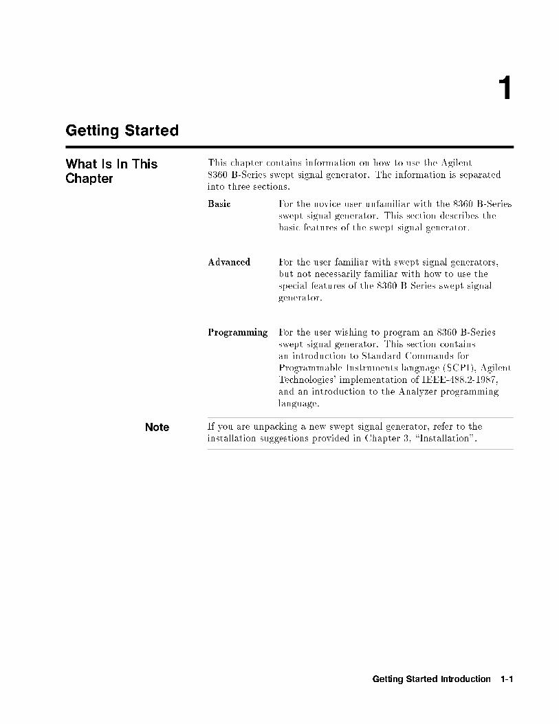
What Is In ThisChapter
This chapter contains information on how to use the Agilent8360 B-Series swept signal generator. The information is separatedinto three sections.
Basic For the novice user unfamiliar with the 8360 B-Seriesswept signal generator. This section describes thebasic features of the swept signal generator.
Advanced For the user familiar with swept signal generators,but not necessarily familiar with how to use thespecial features of the 8360 B-Series swept signalgenerator.
Programming For the user wishing to program an 8360 B-Seriesswept signal generator. This section containsan introduction to Standard Commands forProgrammable Instruments language (SCPI), AgilentTechnologies' implementation of IEEE-488.2-1987,and an introduction to the Analyzer programminglanguage.
Note If you are unpacking a new swept signal generator, refer to theinstallation suggestions provided in Chapter 3, \Installation".
Getting Started Introduction 1-1

How To Use ThisChapter
To use this chapter e�ectively, refer to the tabbed section \MenuMaps". Menu maps can be folded out to be viewed at the same timeas the Getting Started information, as illustrated.
Equipment Used InExamples
The following table lists the equipment used in the operationexamples shown in this chapter. You can substitute equipment, butbe aware that you may get di�erent results than those shown.
Equipment Used In Examples
Equipment RecommendedHP/Agilent
Model Numbers
Power Meter 436A/437B
Power Sensor 8485A
Power Splitter 11667B
Oscilloscope 1740A
mm-Wave Source Module 83556A
Power Ampli�er 8349B
Coupler 11691D
Detector 8474D
1-2 Getting Started Introduction

Getting Started Basic
Introducing the8360 B-SeriesSwept SignalGenerators
The 8360 B-Series swept signal generators are high performance,broadband frequency swept signal generators.
Figure 1-1. The Agilent 83620B Swept Signal Generator
�PRESET� initializes the front panel settings and runs the swept signalgenerator through a brief self-test. In the following examples, unlessstated otherwise, begin by pressing �PRESET�.
Getting Started Basic 1-3
Display Area
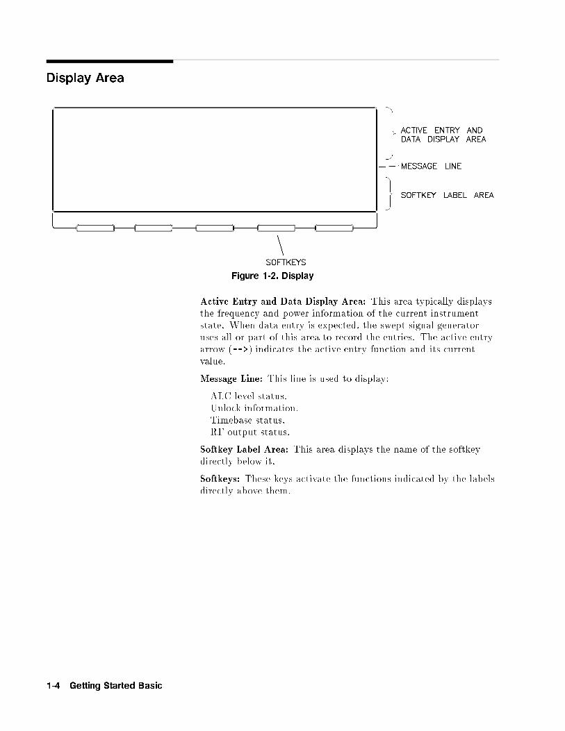
Figure 1-2. Display
Active Entry and Data Display Area: This area typically displaysthe frequency and power information of the current instrumentstate. When data entry is expected, the swept signal generatoruses all or part of this area to record the entries. The active entryarrow (-->) indicates the active entry function and its currentvalue.
Message Line: This line is used to display:
ALC level status.Unlock information.Timebase status.RF output status.
Softkey Label Area: This area displays the name of the softkeydirectly below it.
Softkeys: These keys activate the functions indicated by the labelsdirectly above them.
1-4 Getting Started Basic
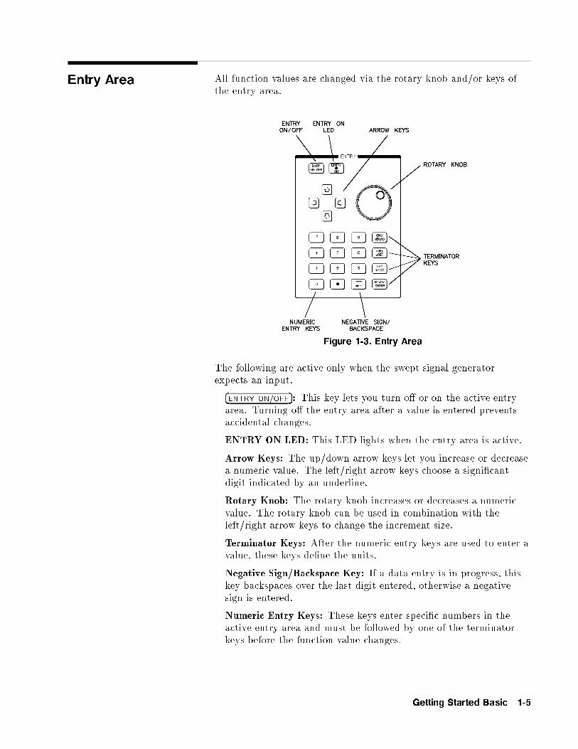
Entry Area All function values are changed via the rotary knob and/or keys ofthe entry area.
Figure 1-3. Entry Area
The following are active only when the swept signal generatorexpects an input.
�ENTRY ON/OFF�: This key lets you turn o� or on the active entryarea. Turning o� the entry area after a value is entered preventsaccidental changes.
ENTRY ON LED: This LED lights when the entry area is active.
Arrow Keys: The up/down arrow keys let you increase or decreasea numeric value. The left/right arrow keys choose a signi�cantdigit indicated by an underline.
Rotary Knob: The rotary knob increases or decreases a numericvalue. The rotary knob can be used in combination with theleft/right arrow keys to change the increment size.
Terminator Keys: After the numeric entry keys are used to enter avalue, these keys de�ne the units.
Negative Sign/Backspace Key: If a data entry is in progress, thiskey backspaces over the last digit entered, otherwise a negativesign is entered.
Numeric Entry Keys: These keys enter speci�c numbers in theactive entry area and must be followed by one of the terminatorkeys before the function value changes.
Getting Started Basic 1-5

CW Operation andStart/StopFrequency Sweep
CW Operation CW operation is one of the major functions of the swept signalgenerator, and is easy to do using front panel keys. In CW operation,the swept signal generator produces a single, low-noise, synthesizedfrequency. Try this example: Press �CW� �1� �2� �.� �3� �4� �5� �6� �7� �8��GHz�.
Check the active entry area. It indicates:
--> CW: 12345.678000 MHz
The data display area indicates CW operation and the frequencythat you entered. The ENTRY ON LED is lit and the green SWEEPLED is o�.
Try other frequencies. Experiment with the rotary knob and thearrow keys as alternate methods of data entry.
Start/Stop FrequencySweep
The swept signal generator can sweep a frequency span as wide asthe frequency range of the instrument, or as narrow as 0 Hz (sweptCW).In start/stop sweep operation, the swept signal generator producesa sweep from the selected start frequency to the selected stopfrequency.For example:
Press �START� �4� �.� �5� �6� �GHz�.
Press �STOP� �7� �.� �8� �9� �GHz�.
The data display area indicates the start frequency and the stopfrequency. The green SWEEP LED is on (periodically o� whensweep is retracing). Because this is the active function, the activeentry area indicates:
--> STOP FREQUENCY: 7890.000000 MHz
Any subsequent entries change the stop frequency. To change thestart frequency, press �START�, which remains the active function untilyou press a di�erent function key.
1-6 Getting Started Basic
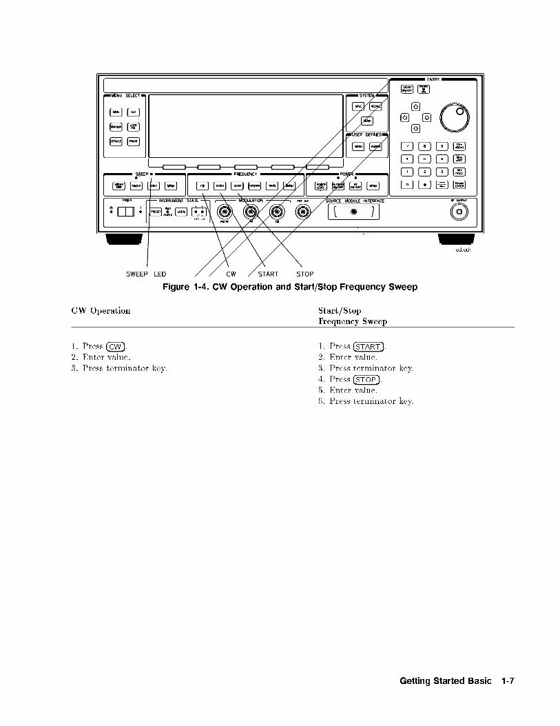
Figure 1-4. CW Operation and Start/Stop Frequency Sweep
CW Operation Start/StopFrequency Sweep
1. Press �CW�. 1. Press �START�.2. Enter value. 2. Enter value.3. Press terminator key. 3. Press terminator key.
4. Press �STOP�.5. Enter value.6. Press terminator key.
Getting Started Basic 1-7
CenterFrequency/SpanOperation
Center frequency/span is another way of establishing sweptoperation. This is just a di�erent way of de�ning sweep limits. As anexample of center frequency/span operation:
Press �CENTER� �4� �GHz�.
Press �SPAN� �1� �GHz�.
The swept signal generator is now sweeping from 3.5 to 4.5 GHz (toview these �gures, press either �START� or �STOP�, then �SPAN�). Thedata display area indicates the center frequency as well as the span.Notice that the green SWEEP LED is on.
While span is the active function, try the rotary knob and arrowkeys. This symmetrical increase or decrease of the frequency spanabout the center frequency is one reason that center frequency/spanswept operation is used instead of start/stop frequency sweep.
Another example illustrates the subtleties of center frequency/span.
Press �CENTER� �4� �GHz�.
Press �SPAN� �8� �GHz�.
Notice that the center frequency changed. This is because the centerfrequency could not accommodate a span of 8 GHz without exceedingthe lower frequency limit of the swept signal generator's speci�edfrequency range. If the low or high frequency range limits areexceeded, the inactive (center or span) function is reset. Experimentwith the rotary knob and the arrow keys as alternate methods ofdata entry.
1-8 Getting Started Basic
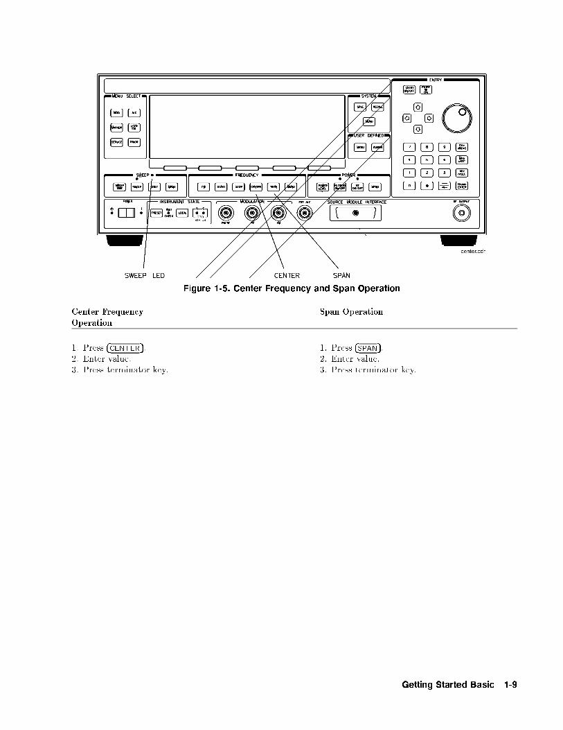
Figure 1-5. Center Frequency and Span Operation
Center FrequencyOperation
Span Operation
1. Press �CENTER�. 1. Press �SPAN�.2. Enter value. 2. Enter value.3. Press terminator key. 3. Press terminator key.
Getting Started Basic 1-9
Power Level andSweep TimeOperation
Power Level Operation The swept signal generator can produce leveled power for CW,swept frequency, or power sweep operation. The selected power levelcan range from -20 dBm (-110 dBm for option 001 swept signalgenerators) to +25 dBm.
For practice: Press �POWER LEVEL� ��� �2� �0� �dB(m)�. The active entryarea shows:
--> POWER LEVEL: �20.00 dBm
If the selected power level is beyond the range of the swept signalgenerator, the closest possible power is shown in both the datadisplay area and the active entry area. If the selected power levelexceeds the maximum leveled power the swept signal generator isable to produce, the unleveled message UNLVLED appears on themessage line. Experiment with the rotary knob and the arrow keysas alternate methods of data entry.
Sweep Time Operation In typical applications the sweep time can vary tremendously, frommilliseconds in a network analyzer system, to more than a minute inthermistor-based power meter systems.
Press �START� �4� �GHz�.Press �STOP� �6� �GHz�.Press �SWEEP TIME� �2� �.� �5� �sec�.
Watch the green SWEEP LED, it blinks every 2.5 seconds. The LEDblinks at each retrace.
For the fastest sweep speed for which all speci�cations areguaranteed, the swept signal generator must be in automatic sweeptime selection.
Refer to menu map 7.Press SWEEP �MENU�.
SelectNNNNNNNNNNNNNNNNNNNNNNNNNNmore 1/3 .
SelectNNNNNNNNNNNNNNNNNNNNNNNNNNNNNNNNNNNNNNSwpTime Auto .
Notice that the active entry area indicates:
--> SWEEP TIME: 100.0 mSec AUTO
When the swept signal generator is in automatic sweep timeselection, the active entry area displays AUTO along with the currentsweep time. Faster sweep speeds than this are possible, turn therotary knob counter-clockwise until the display no longer changes.Notice that AUTO is no longer displayed.
1-10 Getting Started Basic
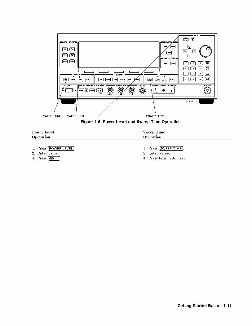
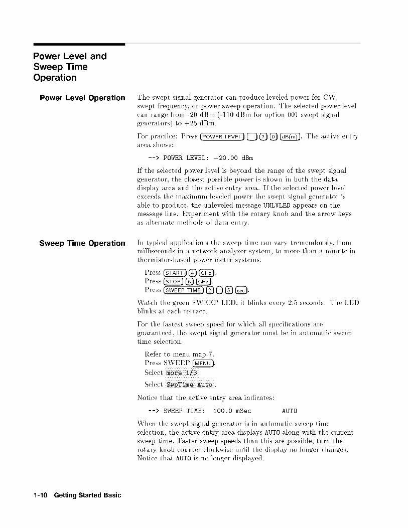
Figure 1-6. Power Level and Sweep Time Operation
Power LevelOperation
Sweep TimeOperation
1. Press �POWER LEVEL�. 1. Press �SWEEP TIME�.2. Enter value. 2. Enter value.3. Press �dB(m)�. 3. Press terminator key.
Getting Started Basic 1-11

Continuous, Single,and Manual SweepOperation
Continuous sweep is the operation mode set when the sweptsignal generator is preset. It simply means that when the sweptsignal generator is performing a swept operation, the sweeps willcontinuously sweep-retrace-sweep-retrace until a di�erent sweep modeis selected. To choose this sweep mode, press �CONT�.
To change from continuous sweep to single sweep operation, press�SINGLE�. This causes the swept signal generator to abort the sweep inprogress and switch to the single sweep mode. This initial keystrokecauses the swept signal generator to switch sweep modes, but itdoes not initiate a single sweep. A second keystroke (press �SINGLE�)initiates a single sweep. When the swept signal generator is in singlesweep operation, the amber LED above the key lights. When theswept signal generator is actually performing a sweep in single sweepmode, the green SWEEP LED lights.
The manual sweep mode lets you use the rotary knob to either sweepfrom the start frequency to the stop frequency or to sweep power.
Refer to menu map 7, SWEEP.
Press �PRESET�.
Press SWEEP �MENU�.
SelectNNNNNNNNNNNNNNNNNNNNNNNNNNNNNNNNNNNNNNManual Sweep .
The active entry area displays:
--> SWEPT MANUAL: XXXXXXXXX MHz
Use the rotary knob to sweep from the start to the stop frequency.The green SWEEP LED is o� in manual sweep mode because thesweeps are synthesized.
1-12 Getting Started Basic
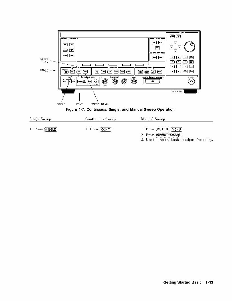
Figure 1-7. Continuous, Single, and Manual Sweep Operation
Single Sweep Continuous Sweep Manual Sweep
1. Press �SINGLE�. 1. Press �CONT�. 1. Press SWEEP �MENU�.
2. PressNNNNNNNNNNNNNNNNNNNNNNNNNNNNNNNNNNNManual Sweep .
3. Use the rotary knob to adjust frequency.
Getting Started Basic 1-13
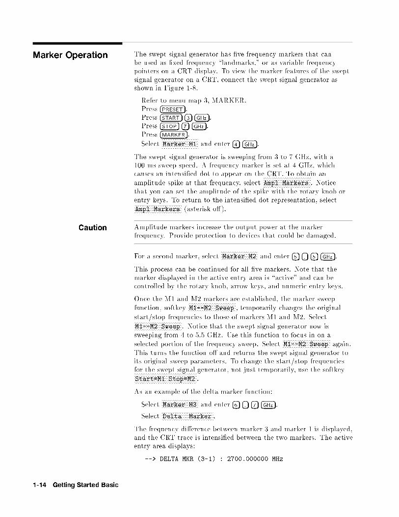
Marker Operation The swept signal generator has �ve frequency markers that canbe used as �xed frequency \landmarks," or as variable frequencypointers on a CRT display. To view the marker features of the sweptsignal generator on a CRT, connect the swept signal generator asshown in Figure 1-8.
Refer to menu map 3, MARKER.Press �PRESET�.Press �START� �3� �GHz�.Press �STOP� �7� �GHz�.Press �MARKER�.
SelectNNNNNNNNNNNNNNNNNNNNNNNNNNNNNMarker M1 and enter �4� �GHz�.
The swept signal generator is sweeping from 3 to 7 GHz, with a100 ms sweep speed. A frequency marker is set at 4 GHz, whichcauses an intensi�ed dot to appear on the CRT. To obtain anamplitude spike at that frequency, select
NNNNNNNNNNNNNNNNNNNNNNNNNNNNNNNNNNNNNNAmpl Markers . Notice
that you can set the amplitude of the spike with the rotary knob orentry keys. To return to the intensi�ed dot representation, selectNNNNNNNNNNNNNNNNNNNNNNNNNNNNNNNNNNNNNNAmpl Markers (asterisk o�).
Caution Amplitude markers increase the output power at the markerfrequency. Provide protection to devices that could be damaged.
For a second marker, selectNNNNNNNNNNNNNNNNNNNNNNNNNNNNNMarker M2 and enter �5� �.� �5� �GHz�.
This process can be continued for all �ve markers. Note that themarker displayed in the active entry area is \active" and can becontrolled by the rotary knob, arrow keys, and numeric entry keys.
Once the M1 and M2 markers are established, the marker sweepfunction, softkey
NNNNNNNNNNNNNNNNNNNNNNNNNNNNNNNNNNNNNNM1--M2 Sweep , temporarily changes the original
start/stop frequencies to those of markers M1 and M2. SelectNNNNNNNNNNNNNNNNNNNNNNNNNNNNNNNNNNNNNNM1--M2 Sweep . Notice that the swept signal generator now issweeping from 4 to 5.5 GHz. Use this function to focus in on aselected portion of the frequency sweep. Select
NNNNNNNNNNNNNNNNNNNNNNNNNNNNNNNNNNNNNNM1--M2 Sweep again.
This turns the function o� and returns the swept signal generator toits original sweep parameters. To change the start/stop frequenciesfor the swept signal generator, not just temporarily, use the softkeyNNNNNNNNNNNNNNNNNNNNNNNNNNNNNNNNNNNNNNNNNNNNNNNNNNStart=M1 Stop=M2 .
As an example of the delta marker function:
SelectNNNNNNNNNNNNNNNNNNNNNNNNNNNNNMarker M3 and enter �6� �.� �7� �GHz�.
SelectNNNNNNNNNNNNNNNNNNNNNNNNNNNNNNNNNNNNNNNNNDelta Marker .
The frequency di�erence between marker 3 and marker 1 is displayed,and the CRT trace is intensi�ed between the two markers. The activeentry area displays:
--> DELTA MKR (3-1) : 2700.000000 MHz
1-14 Getting Started Basic
Marker 1 was chosen because it is selected as the delta markerreference. To change reference markers, select
NNNNNNNNNNNNNNNNNNNNNNNNNNNNNNNNNNNNNNNNNDelta Mkr Ref .
SelectNNNNNNNNM2 as the reference. Watch the display change to indicate:
--> DELTA MKR (3-2) : 1200.000000 MHz
You can choose any of the �ve markers as a reference, but when deltamarker is on, if the reference marker has a frequency value higherthan the last active marker, the di�erence between the frequencies isnegative and is displayed as such by the swept signal generator. TheCRT display continues to intensify the di�erence between the twomarkers.
When delta marker is showing in the active entry area, the ENTRYarea is active. Rotate the rotary knob and watch the frequencydi�erence change. The last active marker (in this case, marker 3)changes frequency value, not the reference marker.
Figure 1-8. Marker Operation
Marker Operation Delta MarkerOperation
1. Press �MARKER�. 1. Press �MARKER�.
2. Select a marker key (NNNNNNNM1 . . .
NNNNNNNM5 ). 2. Select a marker key (
NNNNNNNM1 . . .
NNNNNNNM5 ).
3. Enter value. 3. Enter value.4. Press terminator key. 4. Press terminator key.
5. Select a di�erent marker key (NNNNNNNM1 . . .
NNNNNNNM5 ).
6. Enter value.7. Press terminator key.
8. SelectNNNNNNNNNNNNNNNNNNNNNNNNNNNNNNNNNNNNNDelta Mkr Ref .
9. Select one of the previously chosen markers.10. Press �PRIOR�.
11. SelectNNNNNNNNNNNNNNNNNNNNNNNNNNNNNNNNNNNDelta Marker .
Getting Started Basic 1-15
Saving andRecalling anInstrument State
The save/recall registers store and access a previously set instrumentstate.
For example, set the swept signal generator to sweep from 3 GHz to15 GHz at a �10 dB power level, with markers 1 and 2 set at 4.5 and11.2 GHz.
Press �START� �3� �GHz�.Press �STOP� �1� �5� �GHz�.Press �POWER LEVEL� ��� �1� �0� �dB(m)�.Press �MARKER�.
SelectNNNNNNNNNNNNNNNNNNNNNNNNNNNNNMarker M1 �4� �.� �5� �GHz�.
SelectNNNNNNNNNNNNNNNNNNNNNNNNNNNNNMarker M2 �1� �1� �.� �2� �GHz�.
To save this instrument state in register 1, press �SAVE� �1�. To verifythat the swept signal generator has saved this state:
Press �PRESET�.Press �RECALL� �1�.Press �MARKER�.
The active entry area displays:
--> RECALL REGISTER: 1 RECALLED
Notice the sweep end points, power level, and the asterisks next tothe marker 1 and 2 key labels.
You can save instrument states in registers 1 through 8. Register0 saves the last instrument state before power is turned o�. Whenpower is turned on, register 0 is automatically recalled.
1-16 Getting Started Basic

Figure 1-9. Saving and Recalling an Instrument State
Save Recall
1. Set up swept signal generator as desired. 1. Press �RECALL�.2. Press �SAVE�. 2. Press a number 0 through 8.3. Press a number 1 through 8.
Getting Started Basic 1-17

Power Sweep andPower SlopeOperation
Power Sweep Operation The power sweep function allows the power output to be swept(positive or negative) when the swept signal generator is in theCW frequency mode. The power output of the swept signalgenerator determines the maximum leveled power sweep that can beaccomplished. For this example, refer to the \Menu Map" section.
Zero and calibrate the power meter.
Connect the instruments as shown in Figure 1-10.
Press �CW� �4� �GHz�.
Press �POWER LEVEL� �0� �dBm�.
Press �SWEEP TIME� �2� �sec� �SINGLE�.
Set the power meter to dB[REF] mode.
The swept signal generator is ready to produce a 4 GHz CW signalat 0 dBm power out, with a 2 second sweep rate whenever a singlesweep is executed. The power meter is ready to measure the powerlevel relative to a starting point of 0 dBm.
Press POWER �MENU�.
SelectNNNNNNNNNNNNNNNNNNNNNNNNNNNNNNNNNNNPower Sweep and enter �7� �dB(m)� (asterisk on).
Press �SINGLE�.
Watch the relative power indication on the power meter. At the endof the sweep the power meter indicates +7 dB. The active entry areaon the swept signal generator indicates:
--> POWER SWEEP: 7.00 dB/SWP
Now enter �2� �5� �dB(m)� (power sweep is still the active entryfunction).
Press �SINGLE�.
This time the power meter indicates less than the power sweeprequested. Note that the swept signal generator is unleveled, UNLVD.This happens because the swept signal generator's output powerat the start of the sweep is 0 dB and the requested power sweeptakes the swept signal generator beyond the range where it is able toproduce leveled power. The range of the power sweep is dependenton the ALC range and can be o�set if a step attenuator (Option 001)is present.
SelectNNNNNNNNNNNNNNNNNNNNNNNNNNNNNNNNNNNPower Sweep to turn this function o� (no asterisk).
Press �POWER LEVEL� ��� �2� �0�.
On the power meter, press dB[REF] to reset the reference level.
1-18 Getting Started Basic
SelectNNNNNNNNNNNNNNNNNNNNNNNNNNNNNNNNNNNPower Sweep (asterisk on).
Press �SINGLE�.
The swept signal generator performs a power sweep beginning at�20 dBm and ending at +5 dBm. The power meter indicates+25 dB.
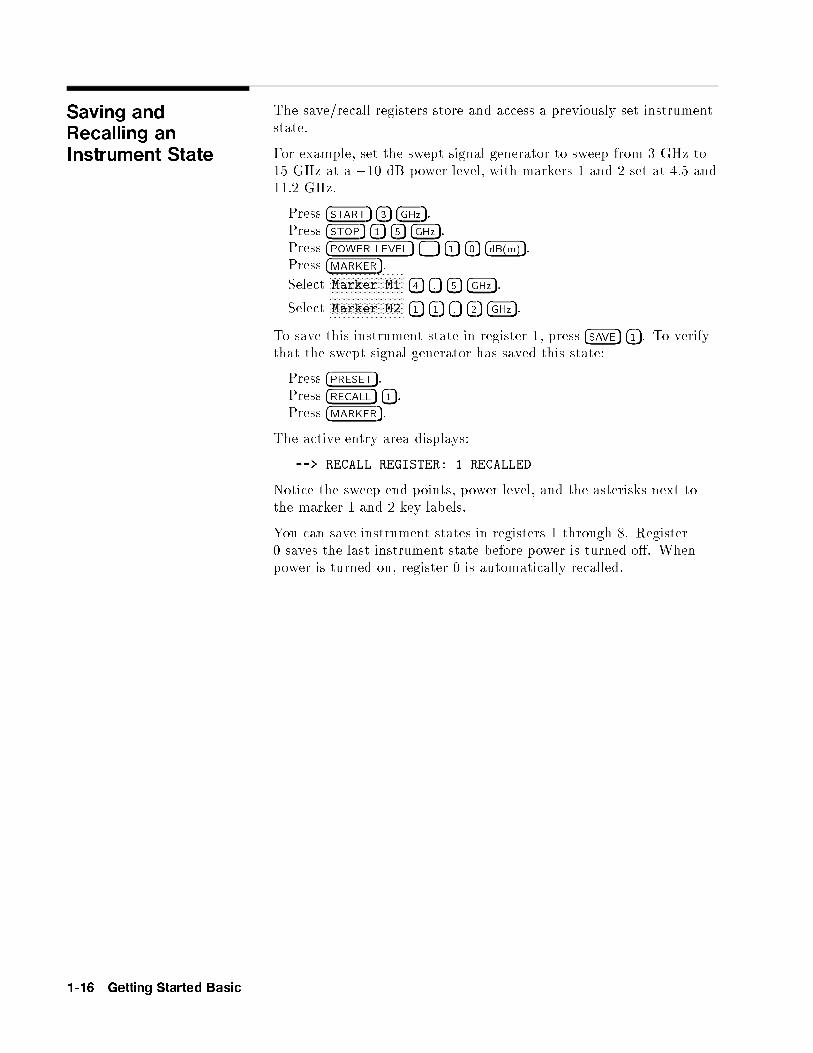
Power Slope Operation This function allows for compensation of high frequency system orcable losses by linearly increasing the power output as the frequencyincreases. For this example, refer to the \Menu Map" section.
PressNNNNNNNNNNNNNNNNNNNNNNNNNNNNNNNNNNNPower Slope , the active entry area displays:
--> RF SLOPE: X.XX dB/GHz, where X is a numeric value.Power slope is now active, notice that an asterisk is next to the keylabel.
Use the entry keys, rotary knob, or arrow keys to enter a value forthe linear slope.
PressNNNNNNNNNNNNNNNNNNNNNNNNNNNNNNNNNNNPower Slope again to turn this feature o�.
Figure 1-10. Power Sweep and Power Slope Operation
Power Sweep Power Slope
1. Press POWER �MENU�. 1. Press POWER �MENU�.
2. SelectNNNNNNNNNNNNNNNNNNNNNNNNNNNNNNNNPower Sweep . 2. Select
NNNNNNNNNNNNNNNNNNNNNNNNNNNNNNNNPower Slope .
3. Enter a value. 3. Enter a value.4. Press terminator key. 4. Press terminator key.
Getting Started Basic 1-19

Advanced
Getting StartedAdvanced
This section of Chapter 1 describes the use of many of the uniquefeatures of the 8360 B-Series swept signal generators. The formatused is similar to the one used on the previous pages. When referredto a menu map number, go to the Menu Map tab and unfold themenu map so that you can view it together with the text.
Some menus have more than one page of softkeys. Select theNNNNNNNNNNNNNNNNNNNNNNNNNNmore m/n softkey to view the next page of softkeys.
NNNNNNNNNNNNNNNNNNNNNNNNNNmore m/n is
not included in the keystrokes given in these procedures.
Table 1-1. Keys Under Discussion in This Section
Paragraph Heading Keys
Externally Leveling the Swept Signal Generator Leveling Point ExtDet
Coupling Factor
POWER LEVEL
Set Atten
Leveling Point PwrMtr
Pwr Mtr Range
Leveling Point Module
Mdl Lev Menu
Working with Mixers/Reverse Power E�ects Uncoupl Atten
Leveling Mode Normal
Working with Spectrum Analyzers/ Leveling Mode ALCoff
Reverse Power E�ects Leveling Mode Search
\Optimizing Swept Signal Generator Performance" Fltness Menu
Delete Menu
Auto Fill Start
Auto Fill Stop
Auto Fill Incr
Mtr Meas Menu
FLTNESS ON/OFF
Enter Freq
Enter Corr
Freq Follow
List Menu
Copy List
Sweep Mode List
Ext Det Cal
Getting Started Advanced 1-21

Advanced
Table 1-1.
Keys Under Discussion in This Section (continued)
Paragraph Heading Keys
\Optimizing Swept Signal Generator Performance" Auto Track
continued Peak RF Always
Peak RF Once
Swp Span Cal Once
Swp Span Cal Always
AM BW Cal Always
AM BW Cal Once
FullUsr Cal
AM On/Off 100%/V
AM On/Off 10dB/V
Deep AM
USER DEFINED MENU
ASSIGN
Using Step Sweep Step Swp Menu
Creating and Using a Frequency List List Menu
Delete Menu
Enter List Freq
Enter List Offset
Enter List Dwell
Pt Trig Menu
Using the Security Features Zero Freq
Save Lock
Clear Memory
Blank Display
Changing the Preset Parameters Save Usr Preset
Preset Mode User
PRESET
For more information, each of these keys has a separate entry inChapter 2.
1-22 Getting Started Advanced

Externally Levelingthe Swept SignalGenerator
In externally leveled operations, the output power from the sweptsignal generator is detected by an external sensor. The output of thisdetector is returned to the leveling circuitry, and the output poweris automatically adjusted to keep power constant at the point ofdetection.
Leveling withDetectors/Couplers
/Splitters
Figure 1-11 illustrates a typical setup for external leveling. Whenexternally leveled, the power level feedback is taken from the externalnegative detector input rather than the internal detector. Thisfeedback voltage controls the ALC system to set the desired RFoutput. Refer to Figure A-1 in Chapter 2 for a block diagram of theswept signal generator's ALC circuitry.
Figure 1-11. ALC Circuit Externally Leveled
Getting Started Advanced 1-23

To level externally:
1. Set up the equipment as shown. For this example, thedetector/coupler setup is used.
2. Refer to menu map 1.3. Press �ALC�.4. Select
NNNNNNNNNNNNNNNNNNNNNNNNNNNNNNNNNNNNNNNNNNNNNNNNNNNNNNNNNNNNNNNNNLeveling Point ExtDet .
5. Set the coupling factor. SelectNNNNNNNNNNNNNNNNNNNNNNNNNNNNNNNNNNNNNNNNNNNNNNNCoupling Factor ��� �2� �0�
�dB(m)�.
Note Power splitters have a coupling factor of 0 dB.
Figure 1-12 shows the input power versus output voltagecharacteristics for typical HP/Agilent diode detectors. From thechart, the leveled power at the diode detector input resulting fromany external level voltage setting may be determined. The range ofpower adjustment is approximately �30 dBm to +18 dBm.
Hint Automatically characterize and compensate for the detectorused by performing a detector calibration. Refer to \UsingDetector Calibration" in the \Optimizing Swept Signal GeneratorPerformance" section.
1-24 Getting Started Advanced

Figure 1-12. Typical Diode Detector Response at 25�C
Getting Started Advanced 1-25

External Leveling Used With the Optional Step Attenuator
Some external leveling applications require low output power fromthe swept signal generator. The swept signal generator automaticallyuncouples the attenuator from the ALC system for all externalleveling points.
Press �POWER LEVEL�. Note the display. It shows:
--> ATTEN 0 dB, POWER LEVEL: 0.00 dBm
For example, leveling the output of a 30 dB gain ampli�er to alevel of �10 dBm requires the output of the swept signal generatorto be around �40 dBm when leveled. At some frequencies thislevel is beyond the range of the ALC modulator alone. If so, theLOW UNLVLED warning message is displayed. Inserting 40 dB ofattenuation results in an ALC level of 0 dBm, which is well withinthe range of the ALC. At 20 GHz, 30 dB attenuation is a betterchoice as it results in an ALC level of �10 dBm. This gives a marginfor AM or other functions that vary the power level.
For optimum display accuracy and minimum noise, the ALClevel should be greater than �10 dBm. This is achieved by usingattenuation equal to the tens digit of output power. Example:desired output power = �43 dBm; use:
--> ATTEN: 40 dB, ALC �3 dBm
1. Press POWER �MENU�.2. Select
NNNNNNNNNNNNNNNNNNNNNNNNNNNNNSet Atten �4� �0� �dB(m)�.
Hint To obtain atness corrected power, refer to \Creating and Applyingthe User Flatness Correction Array" in the \Optimizing Swept SignalGenerator Performance" section.
1-26 Getting Started Advanced
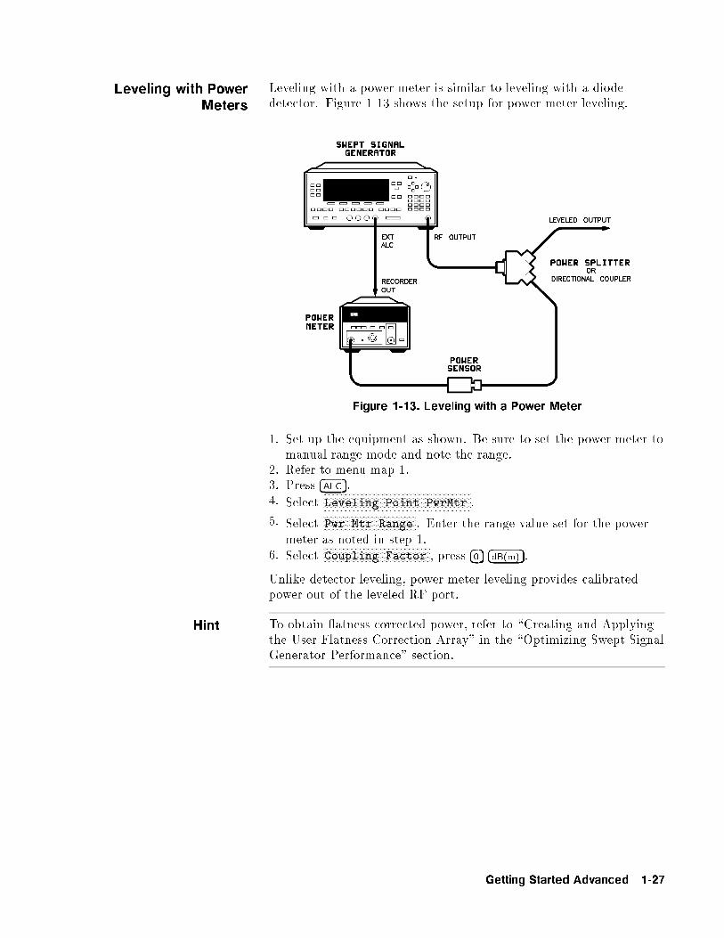
Leveling with PowerMeters
Leveling with a power meter is similar to leveling with a diodedetector. Figure 1-13 shows the setup for power meter leveling.
Figure 1-13. Leveling with a Power Meter
1. Set up the equipment as shown. Be sure to set the power meter tomanual range mode and note the range.
2. Refer to menu map 1.3. Press �ALC�.4. Select
NNNNNNNNNNNNNNNNNNNNNNNNNNNNNNNNNNNNNNNNNNNNNNNNNNNNNNNNNNNNNNNNNLeveling Point PwrMtr .
5. SelectNNNNNNNNNNNNNNNNNNNNNNNNNNNNNNNNNNNNNNNNNPwr Mtr Range . Enter the range value set for the power
meter as noted in step 1.6. Select
NNNNNNNNNNNNNNNNNNNNNNNNNNNNNNNNNNNNNNNNNNNNNNNCoupling Factor , press �0� �dB(m)�.
Unlike detector leveling, power meter leveling provides calibratedpower out of the leveled RF port.
Hint To obtain atness corrected power, refer to \Creating and Applyingthe User Flatness Correction Array" in the \Optimizing Swept SignalGenerator Performance" section.
Getting Started Advanced 1-27

Leveling with MM-waveSource Modules
Millimeter-wave source module leveling is similar to power meterleveling. The following �gures illustrate the setups for leveling with amm-wave source module.
Figure 1-14. MM-wave Source Module Leveling
High power model swept signal generators can externally levelmm-wave source modules to maximum speci�ed power without amicrowave ampli�er.
1-28 Getting Started Advanced
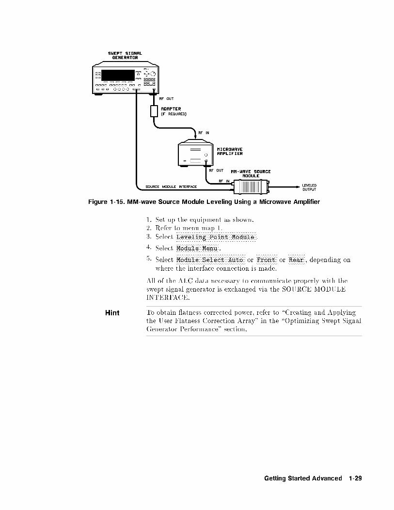
Figure 1-15. MM-wave Source Module Leveling Using a Microwave Amplifier
1. Set up the equipment as shown.2. Refer to menu map 1.3. Select
NNNNNNNNNNNNNNNNNNNNNNNNNNNNNNNNNNNNNNNNNNNNNNNNNNNNNNNNNNNNNNNNNLeveling Point Module .
4. SelectNNNNNNNNNNNNNNNNNNNNNNNNNNNNNNNNNNNModule Menu .
5. SelectNNNNNNNNNNNNNNNNNNNNNNNNNNNNNNNNNNNNNNNNNNNNNNNNNNNNNNNNModule Select Auto or
NNNNNNNNNNNNNNNNNFront or
NNNNNNNNNNNNNNRear , depending on
where the interface connection is made.
All of the ALC data necessary to communicate properly with theswept signal generator is exchanged via the SOURCE MODULEINTERFACE.
Hint To obtain atness corrected power, refer to \Creating and Applyingthe User Flatness Correction Array" in the \Optimizing Swept SignalGenerator Performance" section.
Getting Started Advanced 1-29
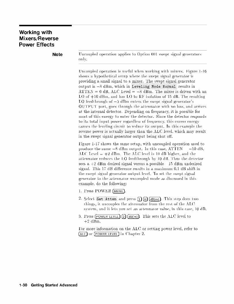
Working withMixers/ReversePower Effects
Note Uncoupled operation applies to Option 001 swept signal generatorsonly.
Uncoupled operation is useful when working with mixers. Figure 1-16shows a hypothetical setup where the swept signal generator isproviding a small signal to a mixer. The swept signal generatoroutput is �8 dBm, which in
NNNNNNNNNNNNNNNNNNNNNNNNNNNNNNNNNNNNNNNNNNNNNNNNNNNNNNNNNNNNNNLeveling Mode Normal results in
ATTEN = 0 dB, ALC Level = �8 dBm. The mixer is driven with anLO of +10 dBm, and has LO to RF isolation of 15 dB. The resultingLO feedthrough of �5 dBm enters the swept signal generator'sOUTPUT port, goes through the attenuator with no loss, and arrivesat the internal detector. Depending on frequency, it is possible formost of this energy to enter the detector. Since the detector respondsto its total input power regardless of frequency, this excess energycauses the leveling circuit to reduce its output. In this example thereverse power is actually larger than the ALC level, which may resultin the swept signal generator output being shut o�.
Figure 1-17 shows the same setup, with uncoupled operation used toproduce the same �8 dBm output. In this case, ATTEN = �10 dB,ALC Level = +2 dBm. The ALC level is 10 dB higher, and theattenuator reduces the LO feedthrough by 10 dB. Thus the detectorsees a +2 dBm desired signal versus a possible �15 dBm undesiredsignal. This 17 dB di�erence results in a maximum 0.1 dB shift inthe swept signal generator output level. To set the swept signalgenerator to the attenuator uncoupled mode as discussed in thisexample, do the following:
1. Press POWER �MENU�.
2. SelectNNNNNNNNNNNNNNNNNNNNNNNNNNNNNSet Atten and press �1� �0� �dB(m)�. This step does two
things, it uncouples the attenuator from the rest of the ALCsystem, and it lets you set an attenuator value, in this case, 10 dB.
3. Press �POWER LEVEL� �2� �dB(m)�. This sets the ALC level to+2 dBm.
For more information on the ALC or setting power level, refer to�ALC� or �POWER LEVEL� in Chapter 2.
1-30 Getting Started Advanced
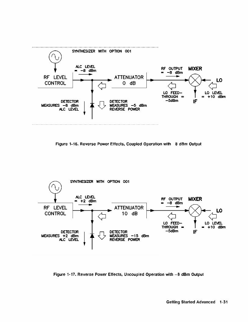
Figure 1-16. Reverse Power Effects, Coupled Operation with �8 dBm Output
Figure 1-17. Reverse Power Effects, Uncoupled Operation with �8 dBm Output
Getting Started Advanced 1-31

Working withSpectrumAnalyzers/ReversePower Effects
Reverse power is a problem with spectrum analyzers that do nothave preselection capability. Some analyzers have as much as+5 dBm LO feedthrough coming out of their RF input, at somefrequencies. The e�ects of reverse power are less in the heterodyneband (0.01 to 2.0 GHz) where the power ampli�er provides somebroadband matching. Similarly, at frequencies above 2.0 GHz,reverse power that is within 10 MHz of the swept signal generator'sfrequency may be partially absorbed by the YIG �lter. If thefrequency di�erence is small enough to be within the levelingsystem bandwidth (typically 10 kHz CW, 200 kHz sweep or AM),the e�ect of reverse power is amplitude modulation of the sweptsignal generator's output. The AM rate equals the di�erence in RFfrequencies. Reverse power problems may be treated by using theunleveled mode. There are two unleveled modes, ALC o� and search.
To set the swept signal generator to the ALC o� mode:
1. Refer to menu map 1.2. Press �ALC�.3. Select
NNNNNNNNNNNNNNNNNNNNNNNNNNNNNNNNNNNNNNNNNNNNNNNNNNNNNNNNNNNNNNLeveling Mode ALCoff .
In this mode, the swept signal generator provides RF power withno ALC correction and therefore requires a power meter to set aparticular power.
To set the swept signal generator to the search mode:
1. Press �ALC�.2. Select
NNNNNNNNNNNNNNNNNNNNNNNNNNNNNNNNNNNNNNNNNNNNNNNNNNNNNNNNNNNNNNLeveling Mode Search .
In this mode, the swept signal generator is in the normal ALCmode until the desired power level is reached, then the ALC isdisconnected.
1-32 Getting Started Advanced
Optimizing SweptSignal GeneratorPerformance
Creating and Applyingthe User FlatnessCorrection Array
The following examples demonstrate the user atness correctionfeature:
1. Using an HP/Agilent 437B power meter to automatically entercorrection data for a swept 4 to 10 GHz measurement.
2. Manually entering correction data for a stepped (List Mode)measurement.
3. Making swept mm-wave measurements, automatically enteringcorrection data for an arbitrary list of correction frequencies.
4. Making scalar analysis measurements with automatically-enteredcorrection data that compensates for power variations at theoutput of a directional bridge.
Each example illustrates how to set up correction tables for adi�erent measurement requirement. Modify the instrument setupsshown to suit your particular needs. Completed correction tablesmay be easily edited if more correction data is required for yourmeasurement. Additional correction frequencies may be addedby using the auto �ll feature or by entering correction frequenciesindividually. The auto �ll feature adds but does not delete correctionfrequencies.
There are two basic front-panel methods of creating a atnesscorrection array. The �rst and quickest method is to use anHP/Agilent 437B power meter. Refer to Figure 1-18 for the setup.The second method is just as accurate, but requires a little moreinteraction between the operator and the instruments. Figure 1-19shows the setup for the second method.
Getting Started Advanced 1-33

Creating a User Flatness Array Automatically, Example 1
In this example, a atness array containing correction frequenciesfrom 4 to 10 GHz at 1 GHz intervals is created. An HP/Agilent 438Bpower meter controlled by the swept signal generator through theinterface bus is used to enter the correction data into the atnessarray.
For this example, refer to menu map 5, POWER.
1. The equipment setup shown in Figure 1-18 assumes that if thesetup has an external leveling con�guration, the steps necessaryto correctly level have been followed. If you have questions aboutexternal leveling, refer to \Externally Leveling the Swept SignalGenerator".
Setup Power Meter
2. Zero and calibrate the power meter/sensor.
3. Enter the appropriate power sensor calibration factors into thepower meter.
4. Enable the power meter/sensor cal factor array. For operatinginformation on the HP/Agilent 437B power, refer to its operatingand service manual.
5. Connect the power sensor to the point where corrected power isdesired.
Figure 1-18. Creating a User Flatness Array Automatically
Note No other devices can be connected to the GPIB cable.
1-34 Getting Started Advanced

Setup Swept Signal Generator Parameters
6. On the swept signal generator, press �PRESET�.
7. FREQUENCY �START� �4� �GHz�, �STOP� �1� �0� �GHz�.
8. �POWER LEVEL� �0� �dB(m)�.
Access User Flatness Correction Menu
9. Press POWER �MENU�. SelectNNNNNNNNNNNNNNNNNNNNNNNNNNNNNNNNNNNNNNFltness Menu .
10. SelectNNNNNNNNNNNNNNNNNNNNNNNNNNNNNNNNNNNDelete Menu
NNNNNNNNNNNNNNNNNNNNNNNNNNNNNNNNDelete All . This step insures that the
atness array is empty.
11. Press �PRIOR�. Leave the delete menu and return to the previoussoftkey menu.
12. Enter the frequency points at which the correction informationwill be taken. Choose either the point-by-point entry methodNNNNNNNNNNNNNNNNNNNNNNNNNNNNNNNNEnter Freq or the automatic frequency point generationNNNNNNNNNNNNNNNNNNNNNNNNNNNNNNNNNNNNNNNNNNNNNNNAuto Fill Start . For this example, select
NNNNNNNNNNNNNNNNNNNNNNNNNNNNNNNNNNNNNNNNNNNNNNNAuto Fill Start
�4� �GHz�.
13. SelectNNNNNNNNNNNNNNNNNNNNNNNNNNNNNNNNNNNNNNNNNNNNAuto Fill Stop �1� �0� �GHz�,
NNNNNNNNNNNNNNNNNNNNNNNNNNNNNNNNNNNNNNNNNNNNAuto Fill Incr �1� �GHz�.
Notice that a frequency list starting at 4 and ending at 10 GHzwith an increment value of 1 GHz is created.
Enter Correction Data into Array
14. SelectNNNNNNNNNNNNNNNNNNNNNNNNNNNNNNNNNNNNNNNNNMtr Meas Menu
NNNNNNNNNNNNNNNNNNNNNNNNNNNNNNNNNNNNNNNNNNNNNNNNNNMeasure Corr All . The power meter
is now under swept signal generator control and is performingthe sequence of steps necessary to generate the correctioninformation at each frequency point.
If a GPIB error message is displayed verify that the interfaceconnections are correct. Check the GPIB address of the powermeter and ensure that it is the same address the swept signalgenerator is using (address 13 is assumed). Refer to the menumap 8, System, for the key sequence necessary to reach softkeyNNNNNNNNNNNNNNNNNNNNNNNNNNNNNNNNMeter Adrs .
Enable User Flatness Correction
15. When the operation is complete, (a message is displayed) the atness correction array is ready to be applied to your setup.Disconnect the power meter/sensor and press �FLTNESS ON/OFF�(amber LED on). The power produced at the point where thepower meter/sensor was disconnected is now calibrated at thefrequencies and power level speci�ed above.
Getting Started Advanced 1-35
Creating a User Flatness Array, Example 2
This example shows how to use the swept signal generator and apower meter in manual entry mode. This example also introducestwo features of the swept signal generator. The softkey
NNNNNNNNNNNNNNNNNNNNNNNNNNNNNNNNNNNFreq Follow
simpli�es the data entry process and the softkeyNNNNNNNNNNNNNNNNNNNNNNNNNNNNNList Mode sets up
a list of arbitrary test frequencies.
The frequency follow feature automatically sets the source to a CWtest frequency equivalent to the active correction frequency in theuser atness correction table. The front panel arrow keys are usedto move around the correction table and enter frequency-correctionpairs. Simultaneously, the swept signal generator test frequencyis updated to the selected correction frequency without exiting thecorrection table.
To further simplify the data entry process, the swept signal generatorallows you to enter correction data into the user atness correctiontable by adjusting the front panel knob until the desired powerlevel is displayed on the power meter. The user atness correctionalgorithm automatically calculates the appropriate correction andenters it into the table. If you already have a table of correction dataprepared, it can be entered directly into the correction table usingthe front-panel keypad of the swept signal generator.
With the list mode feature, you may enter the test frequencies intoa table in any order and specify an o�set (power) and/or a dwelltime for each frequency. When list mode is enabled, the swept signalgenerator steps through the list of frequencies in the order entered.
The user atness correction feature has the capability of copying andentering the frequency list into the correction table. Since the o�setin the list mode table is not active during the user atness correctiondata entry process, the value of the correction data is determined asif no o�set is entered. When user atness correction and list mode(with o�sets) are enabled, the swept signal generator adjusts theoutput power by an amount equivalent to the sum of the correctiondata and o�set for each test frequency. You must make sure that theresulting power level is still within the ALC range of the swept signalgenerator.
1-36 Getting Started Advanced

Figure 1-19. Creating a User Flatness Array
For this example, refer to menu map 5, POWER.
1. The equipment setup shown in Figure 1-19 assumes that if yoursetup has an external leveling con�guration, the steps necessaryto correctly level have been followed. If you have questions aboutexternal leveling, refer to \Externally Leveling the Swept SignalGenerator".
Setup Power Meter
2. Zero and calibrate the power meter/sensor.
3. Connect the power sensor to the point where atness correctedpower is desired.
Setup Swept Signal Generator Parameters
4. On the swept signal generator, press �PRESET�.
5. �POWER LEVEL� �5� �dB(m)�. This sets the test port power to+5 dBm (Po max � Ppath loss).
Create A Frequency List
6. On the swept signal generator, press FREQUENCY �MENU�.
7. SelectNNNNNNNNNNNNNNNNNNNNNNNNNNNNNList Menu
NNNNNNNNNNNNNNNNNNNNNNNNNNNNNNNNNNNNNNNNNNNNNNNEnter List Freq �5� �GHz�. This enters
5 GHz as the �rst frequency in the list array. Entering afrequency automatically sets the o�set to 0 dB and the dwell to10 ms.
8. Enter 18, 13, 11, and 20 GHz to complete this example array.
Getting Started Advanced 1-37

Access User Flatness Correction Menu
9. Press POWER �MENU�. SelectNNNNNNNNNNNNNNNNNNNNNNNNNNNNNNNNNNNNNNFltness Menu .
10. SelectNNNNNNNNNNNNNNNNNNNNNNNNNNNNNNNNNNNDelete Menu
NNNNNNNNNNNNNNNNNNNNNNNNNNNNNNNNDelete All . This step insures that the
atness array is empty.
11. Press �PRIOR�. Leave the delete menu and return to the previoussoftkey menu.
12. SelectNNNNNNNNNNNNNNNNNNNNNNNNNNNNNCopy List This step copies the frequency list into the
correction table in sequential order.
13. SelectNNNNNNNNNNNNNNNNNNNNNNNNNNNNNNNNNNNFreq Follow . This sets the swept signal generator to CW
frequency mode to facilitate taking correction information. Asyou scroll through the correction cells, the swept signal generatorproduces the corresponding CW frequency at 0 dBm.
14. SelectNNNNNNNNNNNNNNNNNNNNNNNNNNNNNNNNEnter Corr . This allows correction value entry.
15. Press �FLTNESS ON/OFF�. This step enables user atness correction.
16. For 5 GHz, set the appropriate power sensor cal factor on thepower meter.
17. Use the swept signal generator rotary knob to adjust for ameasurement of 0.00 dBm on the power meter. Notice that acorrection value is entered at 5 GHz.
18. Use the up arrow key to increment to the next correction cell.
19. For 11 GHz, set the appropriate power sensor cal factor on thepower meter.
20. Use the swept signal generator rotary knob to adjust for ameasurement of 0.00 dBm on the power meter.
21. Repeat this sequence of steps until all the frequency points havea correction value entered.
Activate List Mode
22. Press SWEEP �MENU�. SelectNNNNNNNNNNNNNNNNNNNNNNNNNNNNNNNNNNNNNNNNNNNNNNNSweep Mode List .
23. The atness correction array is ready to be applied to your setup.Disconnect the power meter/sensor. The power produced at thepoint where the power meter/sensor was disconnected is nowcalibrated at the frequencies and power level speci�ed above.
1-38 Getting Started Advanced
Swept mm-wave Measurement with Arbitrary Correction Frequencies,
Example 3
The focus of this example is to use user atness correction to obtain at power at the output of the HP/Agilent 83550 series mm-wavesource modules. In this case we will use non-sequential correctionfrequencies in a swept 26.5 to 40 GHz measurement with anHP/Agilent 83554 source module.
The time it takes for a large quantity of power meter measurementscan be long, therefore, we selected non-sequential correctionfrequencies to target speci�c points or sections of the measurementrange that we assume are more sensitive to power variations.This greatly expedites setting up the user atness correctiontable. The amount of interpolated correction points betweennon-sequential correction frequencies varies. This example uses theHP/Agilent 437B to automatically enter correction data into thearray.
Note Turn o� the swept signal generator before connecting to the sourcemodule interface (SMI) cable, or damage may result.
Getting Started Advanced 1-39
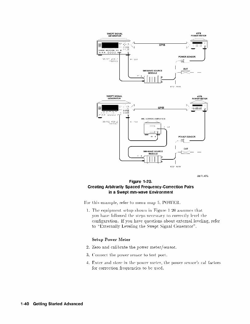
Figure 1-20.
Creating Arbitrarily Spaced Frequency-Correction Pairs
in a Swept mm-wave Environment
For this example, refer to menu map 5, POWER.
1. The equipment setup shown in Figure 1-20 assumes thatyou have followed the steps necessary to correctly level thecon�guration. If you have questions about external leveling, referto \Externally Leveling the Swept Signal Generator".
Setup Power Meter
2. Zero and calibrate the power meter/sensor.
3. Connect the power sensor to test port.
4. Enter and store in the power meter, the power sensor's cal factorsfor correction frequencies to be used.
1-40 Getting Started Advanced

Note U, V, and W-band power sensors are not available fromAgilent Technologies. For these frequencies use the Anritsu ML83APower Meter with the MP715-004 (40 to 60 GHz), the MP716A(50 to 75 GHz), or the MP81B (75 to 110 GHz) power sensors. Sincethe Anritsu model ML83A Power Meter is not capable of internallystoring power sensor cal factors, you must manually correct thedata entry. Refer to example 2 for information on manual entry ofcorrection data.
Setup Swept Signal Generator Parameters
5. Turn on the swept signal generator and press �PRESET�.The following occurs:
The source module's frequency span is displayed on the sweptsignal generator.The swept signal generator's leveling mode is automaticallychanged from internal to \module leveling".The source module's maximum speci�ed power is set anddisplayed.
6. Press FREQUENCY �START� �2� �6� �.� �5� �GHz�, �STOP� �4� �0��GHz�. The frequency sweep is set from 26.5 to 40 GHz.
7. Press �POWER LEVEL� �7� �dBm�. The source module power is set to+7 dBm for maximum power to the device under test.
Access User Flatness Correction Menu
8. Press POWER �MENU�. SelectNNNNNNNNNNNNNNNNNNNNNNNNNNNNNNNNNNNNNNFltness Menu .
9. SelectNNNNNNNNNNNNNNNNNNNNNNNNNNNNNNNNNNNDelete Menu
NNNNNNNNNNNNNNNNNNNNNNNNNNNNNNNNDelete All . This step insures that the
atness array is empty.
10. Press �PRIOR�. Leave the delete menu and return to the previoussoftkey menu.
11. SelectNNNNNNNNNNNNNNNNNNNNNNNNNNNNNNNNEnter Freq �2� �6� �.� �5� �GHz�, to enter 26.5 GHz as
the �rst correction frequency. Enter 31, 32.5, and 40 GHz tocomplete the list. Notice that the frequencies are arbitrarilyspaced.
Getting Started Advanced 1-41
Enter Correction Data into Array
12. SelectNNNNNNNNNNNNNNNNNNNNNNNNNNNNNNNNNNNNNNNNNMtr Meas Menu
NNNNNNNNNNNNNNNNNNNNNNNNNNNNNNNNNNNNNNNNNNNNNNNNNNMeasure Corr All . The power meter
is now under swept signal generator control and is performingthe sequence of steps necessary to generate the correctioninformation at each frequency point.
If a GPIB error message is displayed verify that the interfaceconnections are correct. Check the GPIB address of the powermeter and ensure that it is the same address the swept signalgenerator is using (address 13 is assumed). Refer to the menumap 8, System, for the key sequence necessary to reach softkeyNNNNNNNNNNNNNNNNNNNNNNNNNNNNNNNNMeter Adrs .
Enable User Flatness Correction
13. When the operation is complete, (a message is displayed) the atness correction array is ready to be applied to your setup.
14. To save the swept signal generator parameters including thecorrection table in an internal register, press �SAVE� �n�.(n = number 1 through 8).
15. Disconnect the power meter/sensor and press �FLTNESS ON/OFF�(amber LED on). The power produced at the point where thepower meter/sensor was disconnected is now calibrated at thefrequencies and power level speci�ed above.
1-42 Getting Started Advanced
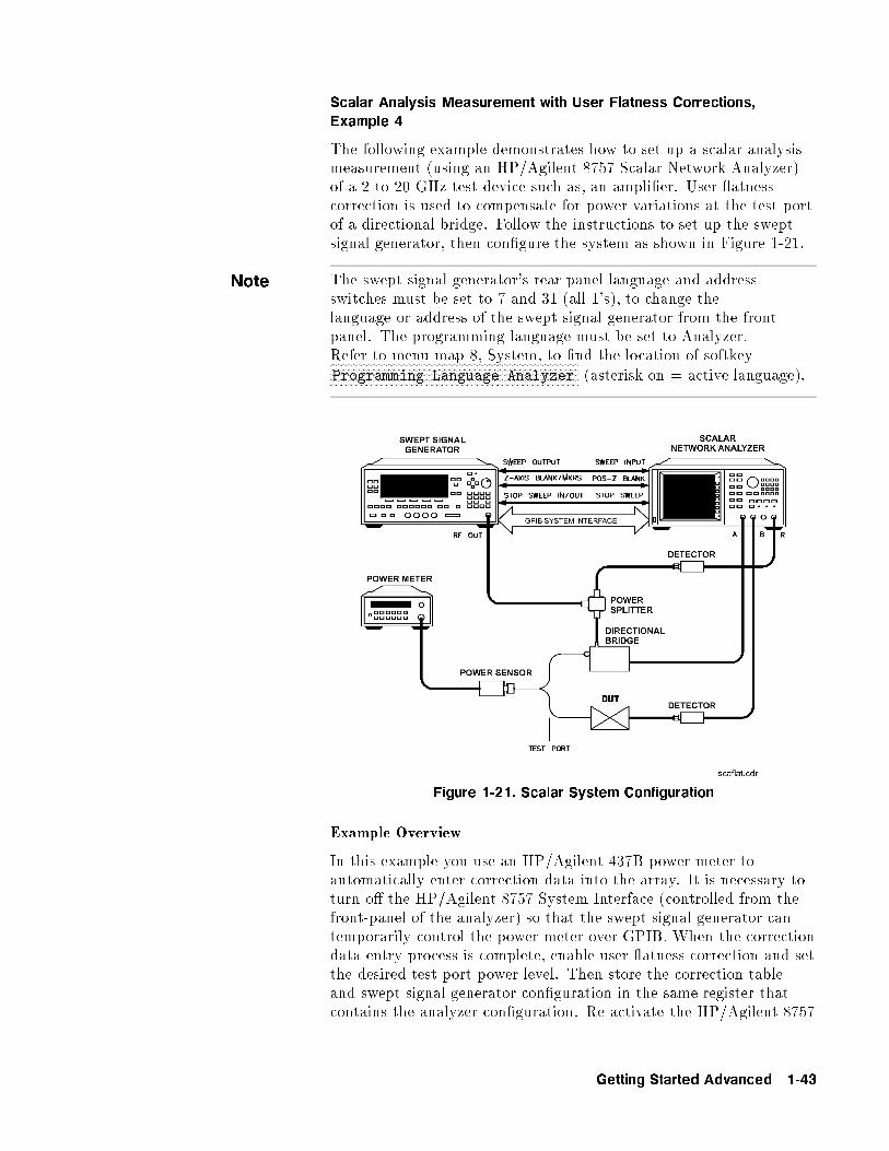
Scalar Analysis Measurement with User Flatness Corrections,
Example 4
The following example demonstrates how to set up a scalar analysismeasurement (using an HP/Agilent 8757 Scalar Network Analyzer)of a 2 to 20 GHz test device such as, an ampli�er. User atnesscorrection is used to compensate for power variations at the test portof a directional bridge. Follow the instructions to set up the sweptsignal generator, then con�gure the system as shown in Figure 1-21.
Note The swept signal generator's rear panel language and addressswitches must be set to 7 and 31 (all 1's), to change thelanguage or address of the swept signal generator from the frontpanel. The programming language must be set to Analyzer.Refer to menu map 8, System, to �nd the location of softkeyNNNNNNNNNNNNNNNNNNNNNNNNNNNNNNNNNNNNNNNNNNNNNNNNNNNNNNNNNNNNNNNNNNNNNNNNNNNNNNNNNNNNNNNNNProgramming Language Analyzer (asterisk on = active language).
Figure 1-21. Scalar System Configuration
Example Overview
In this example you use an HP/Agilent 437B power meter toautomatically enter correction data into the array. It is necessary toturn o� the HP/Agilent 8757 System Interface (controlled from thefront-panel of the analyzer) so that the swept signal generator cantemporarily control the power meter over GPIB. When the correctiondata entry process is complete, enable user atness correction and setthe desired test port power level. Then store the correction tableand swept signal generator con�guration in the same register thatcontains the analyzer con�guration. Re-activate the HP/Agilent 8757
Getting Started Advanced 1-43
System Interface and recall the stored register. Make sure that user atness correction is still enabled before making the measurement.
When an HP/Agilent 437B power meter is used to automaticallyenter the correction data, the correction calibration routineautomatically turns o� any active modulation, then re-activatesthe modulation upon the completion of the data entry process.Therefore, the scalar pulse modulation that is automaticallyenabled in a scalar measurement system is disabled during anHP/Agilent 437B correction calibration.
Note The user atness correction array cannot be stored to a disk. Youmust make sure that the array is stored in one of the eight internalregisters. Recalling a �le from an HP/Agilent 8757 disk will not erasethe current array; therefore you may recall an array from an internalregister, then recall an associated �le from a disk.
For this example, refer to menu map 5, POWER.
1. The equipment setup shown in Figure 1-21 assumes thatyou have followed the steps necessary to correctly level thecon�guration. If you have questions about external leveling, referto \Externally Leveling the Swept Signal Generator".
2. On the analyzer, press �PRESET�. Reset the analyzer and sweptsignal generator to a known state.
Setup System Parameters
3. On the swept signal generator, press FREQUENCY �START� �2��GHz�, �STOP� �2� �0� �GHz�. Set the swept signal generator for afrequency sweep of 2 to 20 GHz.
4. Press �POWER LEVEL� �n� �dBm�. Where n = maximum availablepower.
5. On the analyzer, set up the appropriate measurement(i.e. gain for an ampli�er). Calibrate the measurement (thru andshort/open calibration). Press �SAVE� �1� to store the analyzer'scon�guration and swept signal generator parameters in storageregister 1.
6. Turn o� the HP/Agilent 8757 System Interface. Use the analyzerNNNNNNNNNNNNNNNNNNNNNNNNNNNNNNNNNNNNNNNNNNNNSYSINTF ON OFF softkey found under the SYSTEM menu todeactivate the system interface.
Access User Flatness Correction Menu
7. On the swept signal generator, press POWER �MENU�. SelectNNNNNNNNNNNNNNNNNNNNNNNNNNNNNNNNNNNNNNFltness Menu .
8. SelectNNNNNNNNNNNNNNNNNNNNNNNNNNNNNNNNNNNDelete Menu
NNNNNNNNNNNNNNNNNNNNNNNNNNNNNNNNDelete All . This step insures that the
atness array is empty.
1-44 Getting Started Advanced

9. Press �PRIOR�. Leave the delete menu and return to the previoussoftkey menu.
10. SelectNNNNNNNNNNNNNNNNNNNNNNNNNNNNNNNNNNNNNNNNNNNNNNNAuto Fill Start �2� �GHz�. Set the �rst frequency in
correction table to 2 GHz.
11.NNNNNNNNNNNNNNNNNNNNNNNNNNNNNNNNNNNNNNNNNNNNAuto Fill Stop �2� �0� �GHz�. Set the last frequency incorrection table to 20 GHz.
12.NNNNNNNNNNNNNNNNNNNNNNNNNNNNNNNNNNNNNNNNNNNNAuto Fill Incr �1� �0� �0� �MHz�. Set the frequency increment toevery 100 MHz from 2 to 20 GHz.
Setup Power Meter
13. Zero and calibrate the power meter/sensor.
14. Connect the power sensor to test port.
15. Enter and store in the power meter, the power sensor's cal factorsfor correction frequencies to be used.
Enter Correction Data into Array
16. SelectNNNNNNNNNNNNNNNNNNNNNNNNNNNNNNNNNNNNNNNNNMtr Meas Menu
NNNNNNNNNNNNNNNNNNNNNNNNNNNNNNNNNNNNNNNNNNNNNNNNNNMeasure Corr All . The power meter
is now under swept signal generator control and is performingthe sequence of steps necessary to generate the correctioninformation at each frequency point.
If a GPIB error message is displayed verify that the interfaceconnections are correct. Check the GPIB address of the powermeter and ensure that it is the same address the swept signalgenerator is using (address 13 is assumed). Refer to the menumap 8, System, for the key sequence necessary to reach softkeyNNNNNNNNNNNNNNNNNNNNNNNNNNNNNNNNMeter Adrs .
Enable User Flatness Correction
17. When the operation is complete, (a message is displayed) the atness correction array is ready to be applied to your setup.
18. Disconnect the power meter/sensor.
19. On the swept signal generator, press �POWER LEVEL� �n� �dBm�.Wheren = Po max � Ppath loss for maximum leveled power at the testport.
20. To save the swept signal generator parameters including thecorrection table in an internal register, press �SAVE� �n�.(n = number 1 through 8).
Getting Started Advanced 1-45

Reactivate the HP/Agilent 8757 System Interface
21. Set the analyzer to SYSINTF ON, the analyzer and swept signalgenerator preset.
22. Press �RECALL� �1�. Recall the swept signal generator parametersfrom storage register 1
23. On the swept signal generator, press �FLTNESS ON/OFF� (amberLED on). The power produced at the point where the powermeter/sensor was disconnected is now calibrated at thefrequencies and power level speci�ed above.
1-46 Getting Started Advanced
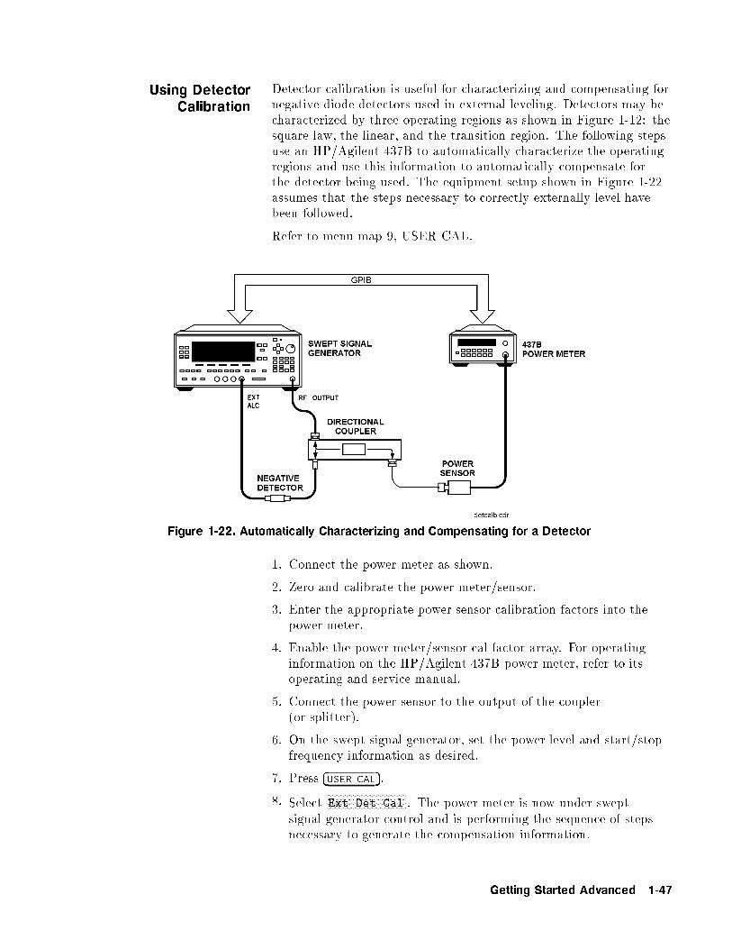
Using DetectorCalibration
Detector calibration is useful for characterizing and compensating fornegative diode detectors used in external leveling. Detectors may becharacterized by three operating regions as shown in Figure 1-12: thesquare law, the linear, and the transition region. The following stepsuse an HP/Agilent 437B to automatically characterize the operatingregions and use this information to automatically compensate forthe detector being used. The equipment setup shown in Figure 1-22assumes that the steps necessary to correctly externally level havebeen followed.
Refer to menu map 9, USER CAL.
Figure 1-22. Automatically Characterizing and Compensating for a Detector
1. Connect the power meter as shown.
2. Zero and calibrate the power meter/sensor.
3. Enter the appropriate power sensor calibration factors into thepower meter.
4. Enable the power meter/sensor cal factor array. For operatinginformation on the HP/Agilent 437B power meter, refer to itsoperating and service manual.
5. Connect the power sensor to the output of the coupler(or splitter).
6. On the swept signal generator, set the power level and start/stopfrequency information as desired.
7. Press �USER CAL�.
8. SelectNNNNNNNNNNNNNNNNNNNNNNNNNNNNNNNNNNNExt Det Cal . The power meter is now under swept
signal generator control and is performing the sequence of stepsnecessary to generate the compensation information.
Getting Started Advanced 1-47

If a GPIB error message is displayed verify that the interfaceconnections are correct. Check the GPIB address of the powermeter and ensure that it is the same address the swept signalgenerator is using (address 13 is assumed). Refer to the menumap 8, System, for the key sequence necessary to reach softkeyNNNNNNNNNNNNNNNNNNNNNNNNNNNNNNNNMeter Adrs .
9. When the operation is complete, (a message is displayed)disconnect the power meter/sensor. The swept signal generatorhas stored the compensation information in its memory and isusing it to calibrate the detector's output voltage relative topower.
1-48 Getting Started Advanced
Using the TrackingFeature Peaking
Peaking is the function that aligns the output �lter (YTM) so thatits passband is centered on the RF output, in CW or manual-sweepmode. Use peaking to obtain the maximum available power andspectral purity, and best pulse envelopes, at any given frequencyabove 2.0 GHz. The YTM is inactive for the low band frequencies(10 MHz to 2.0 GHz).
To peak at the present CW frequency:
Press �USER CAL�.
SelectNNNNNNNNNNNNNNNNNNNNNNNNNNNNNNNNNNNNNNNNNTracking Menu
NNNNNNNNNNNNNNNNNNNNNNNNNNNNNNNNNNNNNNPeak RF Once .
This causes an instantaneous execution of the peaking function. Thisis a one-time implementation of the peaking, where the function isturned on and then turned o�.
To peak at the present CW frequency, and continue to peak at newfrequencies as they are entered:
Press �USER CAL�.
SelectNNNNNNNNNNNNNNNNNNNNNNNNNNNNNNNNNNNNNNNNNTracking Menu
NNNNNNNNNNNNNNNNNNNNNNNNNNNNNNNNNNNNNNNNNNNNPeak RF Always .
If \peak always" is on (denoted by an asterisk next to the keylabel) for an extended period of time, the peaking function willautomatically repeak every seven minutes.
Tracking
Auto track is a more extensive version of peaking. It causes all ofthe YTM tracking calibration constants to be aligned and requiresapproximately 40 to 90 seconds to complete. Tracking is performedfrom 2.0 GHz to the end of the speci�ed frequency range.
Note If the swept signal generator does not have a step attenuator,terminate the RF OUTPUT with a good 50 impedance match suchas a 10 dB attenuator or a power sensor to prevent mistracking.
To enhance the power output and spectral purity of sweptmodes, and to improve tracking performance (especially in harshenvironments having wide temperature variations):
Press �USER CAL�.
SelectNNNNNNNNNNNNNNNNNNNNNNNNNNNNNNNNNNNNNNNNNTracking Menu
NNNNNNNNNNNNNNNNNNNNNNNNNNNNNNNNAuto Track .
Getting Started Advanced 1-49

ALC BandwidthSelection
The ALC bandwidth defaults at factory preset to the auto selectionNNNNNNNNNNNNNNNNNNNNNNNNNNNNNNNNNNNNNNNNNNNNNNNNNNNNNNNNNNNNNNNNNNNNNNNNNNNNNALC Bandwidth Select Auto which selects the appropriate
bandwidth (high or low) for each application. To make thebandwidth selection, the swept signal generator determineswhich functions are activated and uses the decision tree shown inFigure 1-23.
Figure 1-23. Decision Tree for ALC Bandwidth Selection
1-50 Getting Started Advanced

Using Step Sweep 1. Refer to menu map 2.2. Press FREQUENCY �MENU�.3. Select
NNNNNNNNNNNNNNNNNNNNNNNNNNNNNNNNNNNNNNNNNStep Swp Menu .
4. SelectNNNNNNNNNNNNNNNNNNNNNNNNNNNNNStep Size . Enter the desired increment value.
5. SelectNNNNNNNNNNNNNNNNNNNNNNNNNNNNNNNNNNNStep Points . Enter the number of points desired.
6. Determine the dwell time desired, selectNNNNNNNNNNNNNNNNNNNNNNNNNNNNNNNNStep Dwell and enter
a value, or choose the dwell time determined by the ramp modesweep time, select
NNNNNNNNNNNNNNNNNNNNNNNNNNNNNNNNNNNNNNNNNDwell Coupled .
7. Determine the triggering scheme, selectNNNNNNNNNNNNNNNNNNNNNNNNNNNNNNNNNNNNNNNNNNNNNNNNNNNNNNNNNNNNNNNNNStep Swp Pt Trig Auto ,NNNNNNNNNNN
Bus , orNNNNNNNNNNNExt .
8. Press SWEEP �MENU�.9. Select
NNNNNNNNNNNNNNNNNNNNNNNNNNNNNNNNNNNNNNNNNNNNNNNSweep Mode Step , to activate the step frequency mode.
Getting Started Advanced 1-51

Creating and Usinga Frequency List
1. Refer to menu map 2.2. Press FREQUENCY �MENU�.3. Select
NNNNNNNNNNNNNNNNNNNNNNNNNNNNNList Menu .
To use the frequency points of a frequency list to create thefrequency portion of the user atness correction array:
1. Refer to menu map 5.2. Press POWER �MENU�.3. Select
NNNNNNNNNNNNNNNNNNNNNNNNNNNNNNNNNNNNNNFltness Menu .
4. SelectNNNNNNNNNNNNNNNNNNNNNNNNNNNNNCopy List .
1-52 Getting Started Advanced

Using the SecurityFeatures
To access the security menu:
1. Refer to menu map 8.2. Press SYSTEM �MENU�.3. Select
NNNNNNNNNNNNNNNNNNNNNNNNNNNNNNNNNNNNNNNNNSecurity Menu .
Getting Started Advanced 1-53

Changing the PresetParameters
1. Set up the swept signal generator in the desired operation state tobe used as the preset state.
2. Refer to menu map 8.3. Press SYSTEM �MENU�.4. Select
NNNNNNNNNNNNNNNNNNNNNNNNNNNNNNNNNNNNNNNNNNNNNNNNNNSave User Preset .
5. SelectNNNNNNNNNNNNNNNNNNNNNNNNNNNNNNNNNNNNNNNNNNNNNNNNNNPreset Mode User .
Whenever the �PRESET� key is pressed, the swept signal generator willreturn to the operation state setup and saved in steps 1 and 4. Theswept signal generator displays:*** USER DEFINED PRESET RECALLED ***
and also gives you the option of selecting the factory preset state bycreating a factory preset softkey.
1-54 Getting Started Advanced

Programming
Getting StartedProgramming
GPIB, the General Purpose Interface Bus, is the instrument-to-instrument communication system between the swept signalgenerator and up to 14 other instruments. Any instrumenthaving GPIB capability can be interfaced to the swept signalgenerator, including non-HP/Agilent instruments that have \GPIB,"\IEEE-488," \ANSI MC1.1," or \IEC-625" capability (these arecommon generic terms for GPIB; all are electrically equivalentalthough IEC-625 uses a unique connector). This portion of themanual speci�cally describes interfacing the swept signal generator toone type of instrument: a computer.
The �rst part of this section provides general GPIB information.Later, the Standard Commands for Programmable Instrumentslanguage (SCPI) is introduced, and example programs are given.For information on programming in the Control InterfaceIntermediate Language (CIIL), refer to a separate option 700 manualsupplement.
Getting Started Programming 1-55
GPIB GeneralInformation
Interconnecting Cables Figure C-2 shows the swept signal generator rear-panel GPIBconnector and suitable cables, and describes the procedures andlimitations for interconnecting instruments. Cable length restrictions,also described in Figure C-2, must be observed.
Instrument Addresses Each instrument in a GPIB network must have a unique address,ranging in value from 00-30 (decimal). The default address for theswept signal generator is 19, but this can be changed using theNNNNNNNNNNNNNNNNNNNNNNNMy Adrs softkey or rear panel switch as described in the reference
chapter (Chapter 2) under the \8360 Adrs" entry (the examples inthis section use 19 as the address for the swept signal generator).Other instruments use a variety of procedures for setting the address,as described in their operating manuals, but typically either a rearpanel switch or a front panel code is used.
GPIB InstrumentNomenclature
A GPIB instrument is categorized as a \listener," \talker," or\controller," depending on its current function in the network.
Listener
A listener is a device capable of receiving data or commands fromother instruments. Any number of instruments in the GPIB networkcan be listeners simultaneously.
Talker
A talker is a device capable of transmitting data or commands toother instruments. To avoid confusion, a GPIB system allows onlyone device at a time to be an active talker.
Controller
A controller is an instrument, typically a computer, capable ofmanaging the various GPIB activities. Only one device at a time canbe an active controller.
Programming the SweptSignal Generator
The swept signal generator can be controlled entirely by a computer(although the line POWER switch must be operated manually).Several functions are possible only by computer (remote) control.Computer programming procedures for the swept signal generatorinvolve selecting a GPIB command statement, then addingthe speci�c swept signal generator (SCPI, Analyzer, or CIIL)programming codes to that statement to achieve the desiredoperating conditions. The programming codes can be categorizedinto two groups: Those that mimic front panel keystrokes; and thosethat are unique, and have no front panel equivalent.
1-56 Getting Started Programming

In the programming explanations that follow, speci�c examples areincluded that are written in a generic dialect of the BASIC language.BASIC was selected because the majority of GPIB computers haveBASIC language capability. However, other languages can also beused.
GPIB CommandStatements
Command statements form the nucleus of GPIB programming;they are understood by all instruments in the network and, whencombined with the programming language codes, they provide allmanagement and data communication instructions for the system.
An explanation of the fundamental command statements follows.However, some computers use a slightly di�erent terminology,or support an extended or enhanced version of these commands.Consider the following explanations as a starting point, but fordetailed information consult the BASIC language reference manual,the I/O programming guide, and the GPIB manual for the particularcomputer used.
Syntax drawings accompany each statement: All items enclosed bya circle or oval are computer speci�c terms that must be enteredexactly as described; items enclosed in a rectangular box are namesof parameters used in the statement; and the arrows indicate a paththat generates a valid combination of statement elements.
The seven fundamental command statements are as follows:
Abort
Abort abruptly terminates all listener/talker activity on the interfacebus, and prepares all instruments to receive a new command from thecontroller. Typically, this is an initialization command used to placethe bus in a known starting condition. The syntax is:
where the interface select code is the computer's GPIB I/O port,which is typically port 7. Some BASIC examples:
10 ABORT 7
100 IF V>20 THEN ABORT 7
Related statements used by some computers:
ABORTIO (used by HP-80 series computers)
HALT
RESET
Getting Started Programming 1-57

Remote
Remote causes an instrument to change from local control toremote control. In remote control, the front panel keys are disabled(except for the �LOCAL� key and the POWER switch), and the amberREMOTE annunciator is lighted. The syntax is:
where the device selector is the address of the instrument appendedto the GPIB port number. Typically, the GPIB port number is 7,and the default address for the swept signal generator is 19, so thedevice selector is 719. Some BASIC examples:
10 REMOTE 7
which prepares all GPIB instruments for remote operation (althoughnothing appears to happen to the instruments until they areaddressed to talk), or
10 REMOTE 719
which a�ects the GPIB instrument located at address 19, or
10 REMOTE 719, 721, 726, 715
which e�ects four instruments that have addresses 19, 21, 26, and 15.
Related statements used by some computers:
RESUME
Local Lockout
Local Lockout can be used in conjunction with REMOTE to disablethe front panel �LOCAL� key. With the �LOCAL� key disabled, only thecontroller (or a hard reset by the POWER switch) can restore localcontrol. The syntax is:
A BASIC example:
10 REMOTE 719
20 LOCAL LOCKOUT 7
1-58 Getting Started Programming
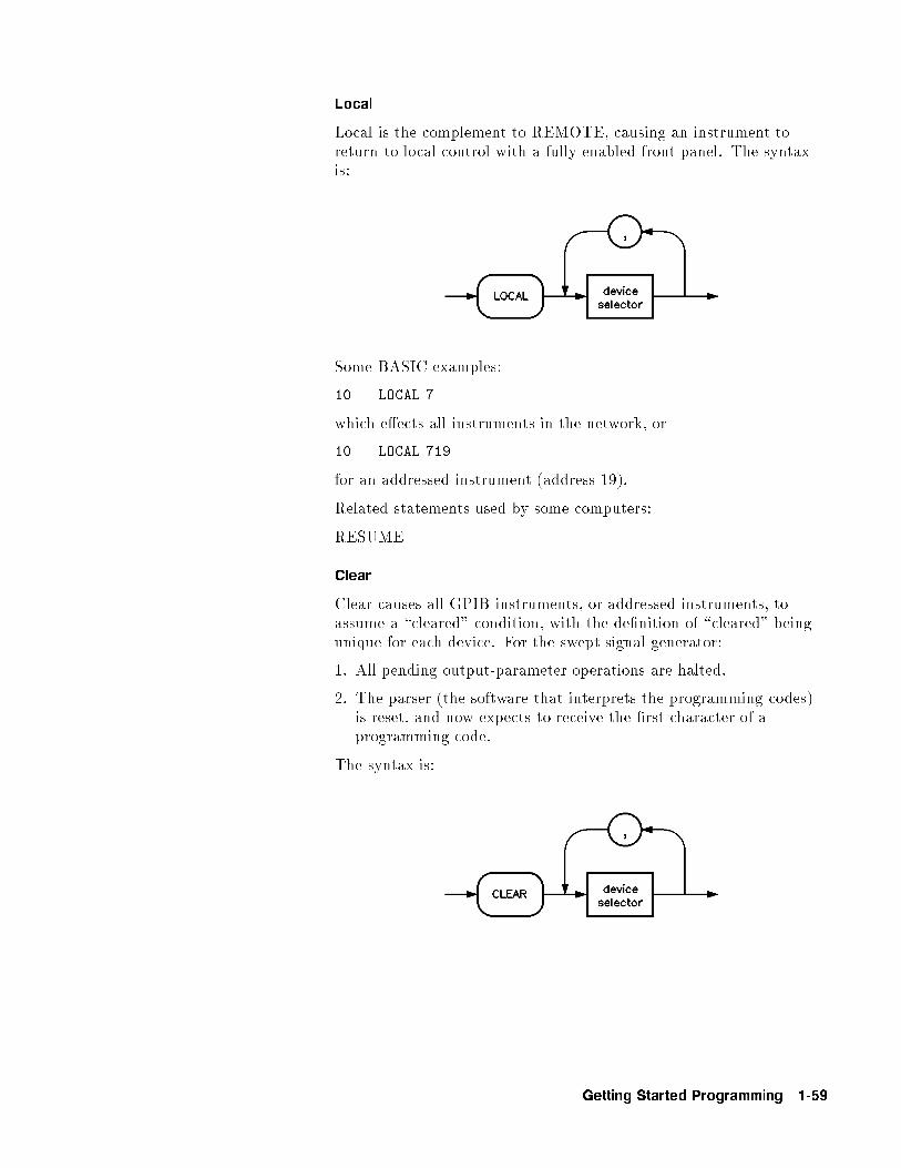
Local
Local is the complement to REMOTE, causing an instrument toreturn to local control with a fully enabled front panel. The syntaxis:
Some BASIC examples:
10 LOCAL 7
which e�ects all instruments in the network, or
10 LOCAL 719
for an addressed instrument (address 19).
Related statements used by some computers:
RESUME
Clear
Clear causes all GPIB instruments, or addressed instruments, toassume a \cleared" condition, with the de�nition of \cleared" beingunique for each device. For the swept signal generator:
1. All pending output-parameter operations are halted.
2. The parser (the software that interprets the programming codes)is reset, and now expects to receive the �rst character of aprogramming code.
The syntax is:
Getting Started Programming 1-59
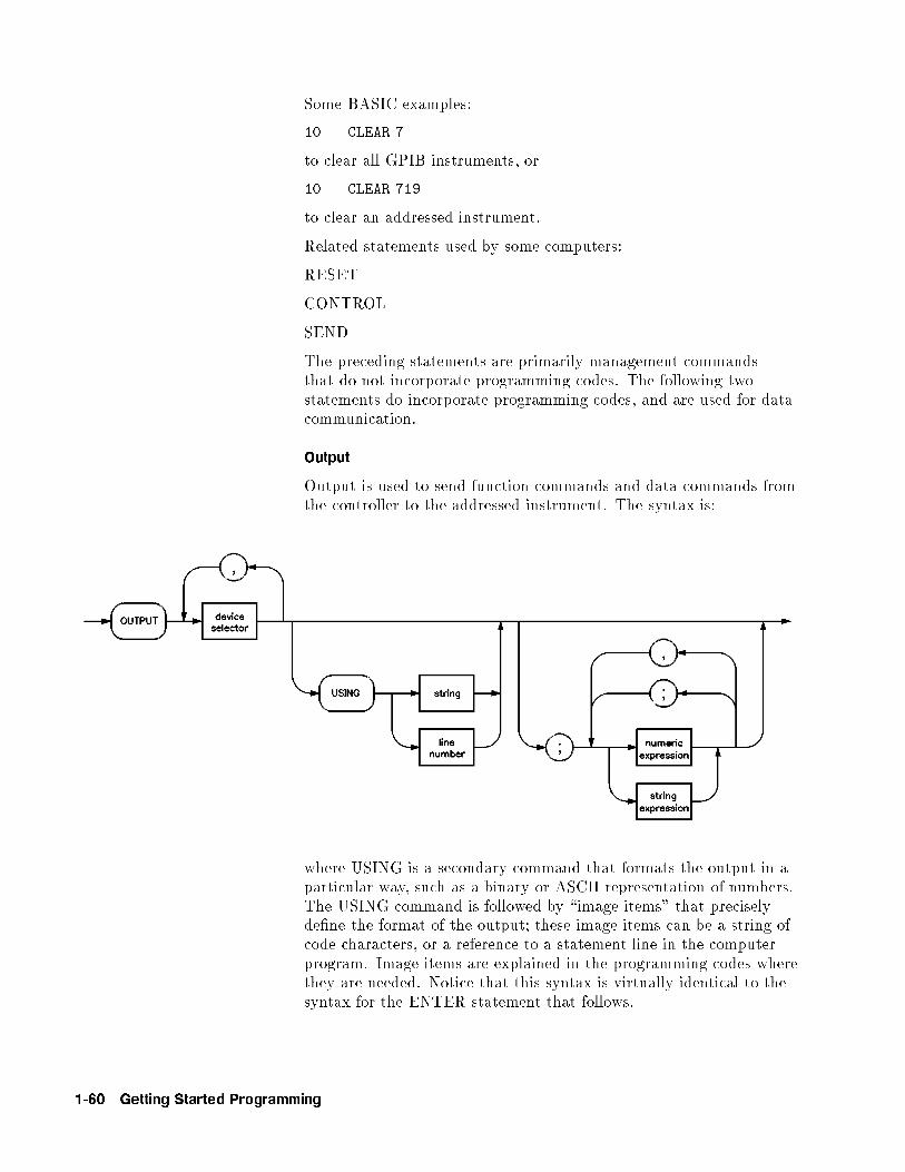
Some BASIC examples:
10 CLEAR 7
to clear all GPIB instruments, or
10 CLEAR 719
to clear an addressed instrument.
Related statements used by some computers:
RESET
CONTROL
SEND
The preceding statements are primarily management commandsthat do not incorporate programming codes. The following twostatements do incorporate programming codes, and are used for datacommunication.
Output
Output is used to send function commands and data commands fromthe controller to the addressed instrument. The syntax is:
where USING is a secondary command that formats the output in aparticular way, such as a binary or ASCII representation of numbers.The USING command is followed by \image items" that preciselyde�ne the format of the output; these image items can be a string ofcode characters, or a reference to a statement line in the computerprogram. Image items are explained in the programming codes wherethey are needed. Notice that this syntax is virtually identical to thesyntax for the ENTER statement that follows.
1-60 Getting Started Programming
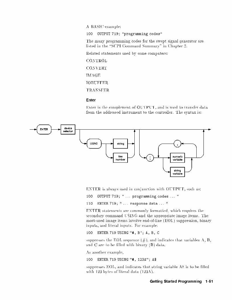
A BASIC example:
100 OUTPUT 719; "programming codes"
The many programming codes for the swept signal generator arelisted in the \SCPI Command Summary" in Chapter 2.
Related statements used by some computers:
CONTROL
CONVERT
IMAGE
IOBUFFER
TRANSFER
Enter
Enter is the complement of OUTPUT, and is used to transfer datafrom the addressed instrument to the controller. The syntax is:
ENTER is always used in conjunction with OUTPUT, such as:
100 OUTPUT 719; " . . . programming codes . . . "
110 ENTER 719; " . . . response data . . . "
ENTER statements are commonly formatted, which requires thesecondary command USING and the appropriate image items. Themost-used image items involve end-of-line (EOL) suppression, binaryinputs, and literal inputs. For example:
100 ENTER 719 USING "#, B"; A, B, C
suppresses the EOL sequence (#), and indicates that variables A, B,and C are to be �lled with binary (B) data.
As another example,
100 ENTER 719 USING "#, 123A"; A$
suppresses EOL, and indicates that string variable A$ is to be �lledwith 123 bytes of literal data (123A).
Getting Started Programming 1-61

Note Be careful when using byte-counting image speci�ers. If therequested number of bytes does not match the actual numberavailable, data might be lost, or the program might enter an endlesswait state.
The suppression of the EOL sequence is frequently necessary toprevent a premature termination of the data input. When notspeci�ed, the typical EOL termination occurs when an ASCII LF(line feed) is received. However, the LF bit pattern couldcoincidentally occur randomly in a long string of binary data, whereit might cause a false termination. Also, the bit patterns for theASCII CR (carriage return), comma, or semicolon might cause a falsetermination. Suppression of the EOL causes the computer to acceptall bit patterns as data, not commands, and relies on the GPIB EOI(end or identify) line for correct end-of-data termination.
Related statements used by some computers:
CONVERT
IMAGE
IOBUFFER
ON TIMEOUT
SET TIMEOUT
TRANSFER
This completes the GPIB Command Statements subsection. Thefollowing material explains the SCPI programming codes, and showshow they are used with the OUTPUT and ENTER GPIB commandstatements.
1-62 Getting Started Programming
Getting Started withSCPI
This section of Chapter 1 describes the use of the StandardCommands for Programmable Instruments language (SCPI). Thissection explains how to use SCPI commands in general. Theinstrument command summary (at the end of this chapter) liststhe speci�c commands available in your instrument. This sectionpresents only the basics of SCPI. If you want to explore the topic ingreater depth, see the paragraph titled, \Related Documents."
Definitions of Terms This section de�nes most terms when they are �rst used, you need ageneral understanding of the terms listed below before you continue.
controller A controller is any computer used to communicatewith a SCPI instrument. A controller can be apersonal computer, a minicomputer, or a plug-in cardin a card cage. Some intelligent instruments can alsofunction as controllers.
instrument An instrument is any device that implements SCPI.Most instruments are electronic measurement orstimulus devices, but this is not a requirement.Similarly, most instruments use an GPIB interfacefor communication. The same concepts applyregardless of the instrument function or the type ofinterface used.
programmessage
A program message is a combination of oneor more properly formatted SCPI commands.Program messages always go from a controller to aninstrument. Program messages tell the instrumenthow to make measurements and output signals.
responsemessage
A response message is a collection of data in speci�cSCPI formats. Response messages always go from aninstrument to a controller or listening instrument.Response messages tell the controller about theinternal state of the instrument and about measuredvalues.
command A command is an instruction in SCPI. Youcombine commands to form messages that controlinstruments. In general, a command consists ofmnemonics (keywords), parameters, and punctuation.
query A query is a special type of command. Queriesinstruct the instrument to make response dataavailable to the controller. Query mnemonics alwaysend with a question mark.
Getting Started Programming 1-63
Standard Notation This section uses several forms of notation that have speci�cmeaning.
Command Mnemonics
Many commands have both a long and a short form, and you mustuse either one or the other (SCPI does not accept a combinationof the two). Consider the FREQuency command, for example. Theshort form is FREQ and the long form is FREQUENCY (this notationstyle is a shorthand to document both the long and short form ofcommands). SCPI is not case sensitive, so fREquEnCy is just as validas FREQUENCY, but FREQ and FREQUENCY are the only valid forms ofthe FREQuency command.
Angle Brackets
Angle brackets indicate that the word or words enclosed representsomething other than themselves. For example, <new line>
represents the ASCII character with the decimal value 10. Similarly,<^END>means that EOI is asserted on the GPIB interface. Wordsin angle brackets have much more rigidly de�ned meaning thanwords used in ordinary text. For example, this section uses the word\message" to talk about messages generally. But the bracketed words<program message> indicate a precisely de�ned element of SCPI.If you need them, you can �nd the exact de�nitions of words such as<program message> in a syntax diagram.
How to Use Examples It is important to understand that programming with SCPIactually requires knowledge of two languages. You must knowthe programming language of your controller (BASIC, C, Pascal)as well as the language of your instrument (SCPI). The semanticrequirements of your controller's language determine how the SCPIcommands and responses are handled in your application.
Command Examples
Command examples look like this:
:FREQuency:CW?
This example tells you to put the string :FREQuency:CW? in theoutput statement appropriate to your application programminglanguage. If you encounter problems, study the details of how theoutput statement handles message terminators such as <new line>.If you are using simple OUTPUT statements in HP BASIC, this istaken care of for you. In HP BASIC, you type:
OUTPUT Source;":FREQuency:CW?"
Command examples do not show message terminators becausethey are used at the end of every program message. \Details of
1-64 Getting Started Programming

Commands and Responses," discusses message terminators in moredetail.
Response Examples
Response examples look like this:
1.23
These are the characters you would read from an instrumentafter sending a query command. To actually pull them from theinstrument into the controller, use the input statement appropriateto your application programming language. If you have problems,study the details of how the input statement operates. In particular,investigate how the input statement handles punctuation characterssuch as comma and semicolon, and how it handles <new line> andEOL.
To enter the previous response in HP BASIC, you type:
ENTER Source;CW_frequency
Response examples do not show response message terminatorsbecause they are always <new line> <^END>. These terminatorsare typically automatically handled by the input statement. Theparagraph titled \Details of Commands and Responses" discussesmessage terminators in more detail.
Getting Started Programming 1-65
Essentials forBeginners
This subsection discusses elementary concepts critical to �rst-timeusers of SCPI. Read and understand this subsection before going onto another. This subsection includes the following topics:
Program and ResponseMessages
These paragraphs introduce thebasic types of messages sent betweeninstruments and controllers.
Subsystem Command Trees These paragraphs describe thetree structure used in subsystemcommands.
Subsystem Command Tables These paragraphs present thecondensed tabular format used fordocumenting subsystem commands.
Reading Instrument Errors These paragraphs explain how to readand print an instrument's internalerror messages.
Example Programs These paragraphs contain two simplemeasurement programs that illustratebasic SCPI programming principles.
Program and ResponseMessages
To understand how your instrument and controller communicateusing SCPI, you must understand the concepts of program andresponse messages. Program messages are the formatted data sentfrom the controller to the instrument. Conversely, response messagesare the formatted data sent from the instrument to the controller.Program messages contain one or more commands, and responsemessages contain one or more responses.
The controller may send commands at any time, but the instrumentsends responses only when speci�cally instructed to do so. Thespecial type of command used to instruct the instrument to senda response message is the query. All query mnemonics end with aquestion mark. Queries return either measured values or internalinstrument settings. Any internal setting that can be programmedwith SCPI can also be queried.
Forgiving Listening and Precise Talking
SCPI uses the concept of forgiving listening and precise talkingoutlined in IEEE 488.2. Forgiving listening means that instrumentsare very exible in accepting various command and parameterformats. For example, the swept signal generator accepts either:POWer:STATe ON or :POWer:STATe 1 to turn RF output on. Precisetalking means that the response format for a particular query isalways the same. For example, if you query the power state when itis on (using :POWer:STATe?), the response is always 1, regardless ofwhether you previously sent :POWer:STATe 1 or :POWer:STATe ON.
1-66 Getting Started Programming

Types of Commands
Commands can be separated into two groups, common commandsand subsystem commands. Common commands are generally notmeasurement related. They are used to manage macros, statusregisters, synchronization, and data storage. Common commandsare easy to recognize because they all begin with an asterisk,such as *IDN?, *OPC, and *RST. Common commands are de�nedby IEEE 488.2. Subsystem commands include all measurementfunctions and some general purpose functions. Subsystem commandsare distinguished by the colon used between keywords, as in:FREQuency:CW?. Each command subsystem is a set of commandsthat roughly corresponds to a functional block inside the instrument.For example, the POWer subsystem contains commands for powergeneration, while the STATus subsystem contains commands foraccessing status registers.
Figure 1-24. SCPI Command Types
The remaining paragraphs in this subsection discuss subsystemcommands in more detail. Remember, some commands areimplemented in one instrument and not in another, depending on itsmeasurement function.
Getting Started Programming 1-67
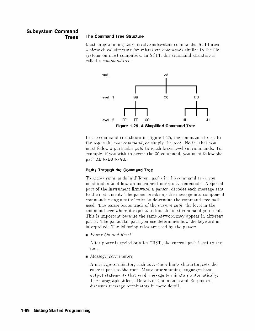
Subsystem CommandTrees The Command Tree Structure
Most programming tasks involve subsystem commands. SCPI usesa hierarchical structure for subsystem commands similar to the �lesystems on most computers. In SCPI, this command structure iscalled a command tree.
Figure 1-25. A Simplified Command Tree
In the command tree shown in Figure 1-25, the command closest tothe top is the root command , or simply the root. Notice that youmust follow a particular path to reach lower level subcommands. Forexample, if you wish to access the GG command, you must follow thepath AA to BB to GG.
Paths Through the Command Tree
To access commands in di�erent paths in the command tree, youmust understand how an instrument interprets commands. A specialpart of the instrument �rmware, a parser , decodes each message sentto the instrument. The parser breaks up the message into componentcommands using a set of rules to determine the command tree pathused. The parser keeps track of the current path, the level in thecommand tree where it expects to �nd the next command you send.This is important because the same keyword may appear in di�erentpaths. The particular path you use determines how the keyword isinterpreted. The following rules are used by the parser:
Power On and Reset
After power is cycled or after *RST, the current path is set to theroot.
Message Terminators
A message terminator, such as a <new line> character, sets thecurrent path to the root. Many programming languages haveoutput statements that send message terminators automatically.The paragraph titled, \Details of Commands and Responses,"discusses message terminators in more detail.
1-68 Getting Started Programming
Colon
When it is between two command mnemonics, a colon moves thecurrent path down one level in the command tree. For example,the colon in MEAS:VOLT speci�es that VOLT is one level below MEAS.When the colon is the �rst character of a command, it speci�esthat the next command mnemonic is a root level command. Forexample, the colon in :INIT speci�es that INIT is a root levelcommand.
Semicolon
A semicolon separates two commands in the same message withoutchanging the current path.
Whitespace
White space characters, such as <tab> and <space>, are generallyignored. There are two important exceptions. White space inside akeyword, such as :FREQ uency, is not allowed. You must use whitespace to separate parameters from commands. For example, the<space> between LEVel and 6.2 in the command :POWer:LEVel
6.2 is mandatory. White space does not a�ect the current path.
Commas
If a command requires more than one parameter, you mustseparate adjacent parameters using a comma. Commas do nota�ect the current path.
Common Commands
Common commands, such as *RST, are not part of any subsystem.An instrument interprets them in the same way, regardless of thecurrent path setting.
Figure 1-26 shows examples of how to use the colon and semicolon tonavigate e�ciently through the command tree.
Getting Started Programming 1-69
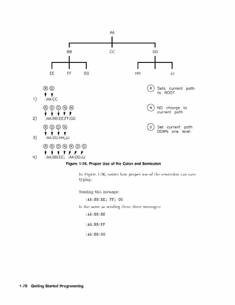
Figure 1-26. Proper Use of the Colon and Semicolon
In Figure 1-26, notice how proper use of the semicolon can savetyping.
Sending this message:
:AA:BB:EE; FF; GG
Is the same as sending these three messages:
:AA:BB:EE
:AA:BB:FF
:AA:BB:GG
1-70 Getting Started Programming

Subsystem CommandTables
These paragraphs introduce a more complete, compact way ofdocumenting subsystems using a tabular format. The commandtable contains more information than just the command hierarchyshown in a graphical tree. In particular, these tables list commandparameters for each command and response data formats for queries.To begin this exploration of command tables, consider a simpli�edSWEep subsystem for the swept signal generator in both the graphicaland tabular formats.
Figure 1-27. Simplified SWEep Command Tree
Table 1-2. SWEep Command Table
Command Parameters ParameterType
:SWEep
:DWELl
:AUTO state BooleanjONCE
:GENeration
:MANual
:POINt
[:RELative]
Reading the Command Table
Note the three columns in the command table labeled Command ,Parameters , and Parameter Type. Commands closest to the rootlevel are at the top of the table. Commands in square bracketsare implied commands, which are discussed in later paragraphs.If a command requires one or more parameters in addition to thekeyword, the parameter names are listed adjacent to the command.Parameters in square brackets are optional parameters, which arediscussed in later paragraphs. If the parameter is not in squarebrackets, it is required and you must send a valid setting for it with
Getting Started Programming 1-71

the matching command. The parameter type is listed adjacent toeach named parameter.
More About Commands
Query and Event Commands. Because you can query any value thatyou can set, the query form of each command is not shown explicitlyin the command tables. For example, the presence of the swept signalgenerator :SWEep:DWELl command implies that a :SWEep:DWELl?
also exists. If you see a table containing a command ending witha question mark, it is a query only command. Some commandsare events , and cannot be queried. An event has no correspondingsetting if it causes something to happen inside the instrument at aparticular instant. For example, :INITiate:IMMediate causes acertain trigger sequence to initiate. Because it is an event, there is noquery form of :INITiate:IMMediate.
Implied Commands. Implied commands appear in square bracketsin the command table. If you send a subcommand immediatelypreceding an implied command, but do not send the impliedcommand, the instrument assumes you intend to use the impliedcommand, and behaves just as if you had sent it. Note that thismeans the instrument expects you to include any parametersrequired by the implied command. The following example illustratesequivalent ways to program the swept signal generator using explicitand implied commands.
Example swept signal generator commands with and without animplied commands:
:SWEep:MANual:RELative 6 using explicit commands
:SWEep:MANual 6 using implied commands
Optional Parameters. Optional parameter names are enclosed insquare brackets in the command table. If you do not send a valuefor an optional parameter, the instrument chooses a default value.The instrument's command dictionary documents the values used foroptional parameters.
Program Message Examples
The following parts of the swept signal generator SCPI command setwill be used to demonstrate how to create complete SCPI programmessages:
:FREQuency
[:CW]
:MULTiplier
:STATE
:POWER
[:LEVEL]
1-72 Getting Started Programming
Example 1: "FREQuency:CW 5 GHZ; MULTiplier 2"
The command is correct and will not cause errors. It is equivalent tosending:"FREQuency:CW 5 GHZ; :FREQuency:MULTiplier 2".
Example 2: "FREQuency 5 GHZ; MULTiplier 2"
This command results in a command error. The command makesuse of the default [:CW] node. When using a default node, there isno change to the current path position. Since there is no command"MULT" at the root, an error results. A correct way to send this is:"FREQ 5 GHZ; FREQ:MULT 2" or as in example 1.
Example 3: "FREQuency:MULTiplier 2; MULTiplier:STATE ON;
FREQuency:CW 5 GHZ"
This command results in a command error. The FREQ:CW portionof the command is missing a leading colon. The path level is droppedat each colon until it is in the FREQ:MULT subsystem. So when theFREQ:CW command is sent, it causes confusion because no suchnode occurs in the FREQ:MULT subsystem. By adding a leadingcolon, the current path is reset to the root. The corrected commandis:"FREQuency:MULTiplier 2; MULTiplier:STATE ON; :FREQuency:CW
5 GHZ".
Example 4: "FREQ 5 GHZ; POWER 4 DBM"
Notice that in this example the keyword short form is used. Thecommand is correct. It utilizes the default nodes of [:CW] and[:LEVEL]. Since default nodes do not a�ect the current path, it isnot necessary to use a leading colon before POWER.
Parameter Types
As you saw in the example command table for SWEep, there areseveral types of parameters. The parameter type indicates whatkind of values are valid instrument settings. The most commonlyused parameter types are numeric, extended numeric, discrete, andBoolean. These common types are discussed brie y in the followingparagraphs. The paragraph titled \Details of Commands andResponses" explains all parameter types in greater depth.
Numeric Parameters. Numeric parameters are used in bothsubsystem commands and common commands. Numeric parametersaccept all commonly used decimal representations of numbersincluding optional signs, decimal points, and scienti�c notation. If aninstrument accepts only speci�c numeric values, such as integers, itautomatically rounds numeric parameters to �t its needs.
Getting Started Programming 1-73
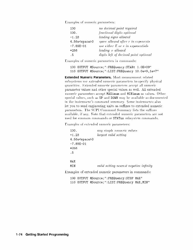
Examples of numeric parameters:
100 no decimal point required
100. fractional digits optional
-1.23 leading signs allowed
4.56e<space>3 space allowed after e in exponents
-7.89E-01 use either E or e in exponentials
+256 leading + allowed
.5 digits left of decimal point optional
Examples of numeric parameters in commands:
100 OUTPUT @Source;":FREQuency:STARt 1.0E+09"
110 OUTPUT @Source;":LIST:FREQuency 10.0e+9,1e+7"
Extended Numeric Parameters. Most measurement relatedsubsystems use extended numeric parameters to specify physicalquantities. Extended numeric parameters accept all numericparameter values and other special values as well. All extendednumeric parameters accept MAXimum and MINimum as values. Otherspecial values, such as UP and DOWN may be available as documentedin the instrument's command summary. Some instruments alsolet you to send engineering units as su�xes to extended numericparameters. The SCPI Command Summary lists the su�xesavailable, if any. Note that extended numeric parameters are notused for common commands or STATus subsystem commands.
Examples of extended numeric parameters:
100. any simple numeric values
-1.23
4.56e<space>3
-7.89E-01
+256
.5
MAX
largest valid setting
MIN valid setting nearest negative in�nity
Examples of extended numeric parameters in commands:
100 OUTPUT @Source;":FREQuency:STOP MAX"
110 OUTPUT @Source;":LIST:FREQuency MAX,MIN"
1-74 Getting Started Programming

Discrete Parameters. Use discrete parameters to program settingsthat have a �nite number of values. Discrete parameters usemnemonics to represent each valid setting. They have a long and ashort form, like command mnemonics. You can use mixed upper andlower case letters for discrete parameters.
Examples of discrete parameters:
INTernal level internally
DIODe level using an external diode
PMETer level using an external power meter
MMHead Level using a mm-wave source module
Examples of discrete parameters in commands:
100 OUTPUT @Source;":POWer:ALC:SOURce INT"
110 OUTPUT @Source;":POWer:ALC:SOURce mmh"
Although discrete parameters values look like command keywords,do not confuse the two. In particular, be sure to use colons andspaces properly. Use a colon to separate command mnemonics fromeach other. Use a space to separate parameters from commandmnemonics.
Boolean Parameters. Boolean parameters represent a single binarycondition that is either true or false. There are only four possiblevalues for a Boolean parameter.
Examples of Boolean parameters:
ON Boolean TRUE, upper/lower case allowed
OFF Boolean FALSE, upper/lower case allowed
1 Boolean TRUE
0 Boolean FALSE
Examples of Boolean parameters in commands:
100 OUTPUT @Source;":FM:STATe On"
110 OUTPUT @Source;":AM:STATe 1"
Getting Started Programming 1-75

Reading InstrumentErrors
When debugging a program, you may want to know if an instrumenterror has occurred. Some instruments can display error messages ontheir front panels. If your instrument cannot do this, you can put thefollowing code segment in your program to read and display errormessages.
10 !
20 ! The rest of your
30 ! variable declarations40 !
50 DIM Err_msg$[75]
60 INTEGER Err_num
70 !
80 ! Part of your program
90 ! that generates errors
100 !
110 !
200 REPEAT
210 OUTPUT @Box;":SYST:ERR?"
220 ! Query instrument error
230 ENTER @Box;Err_num,Err_msg$
240 ! Read error #, message
250 PRINT Err_num,Err_msg$
260 ! Print error message
270 UNTIL Err_num = 0
280 ! Repeat until no errors
290 !
300 ! The rest of your program
310 !
1-76 Getting Started Programming
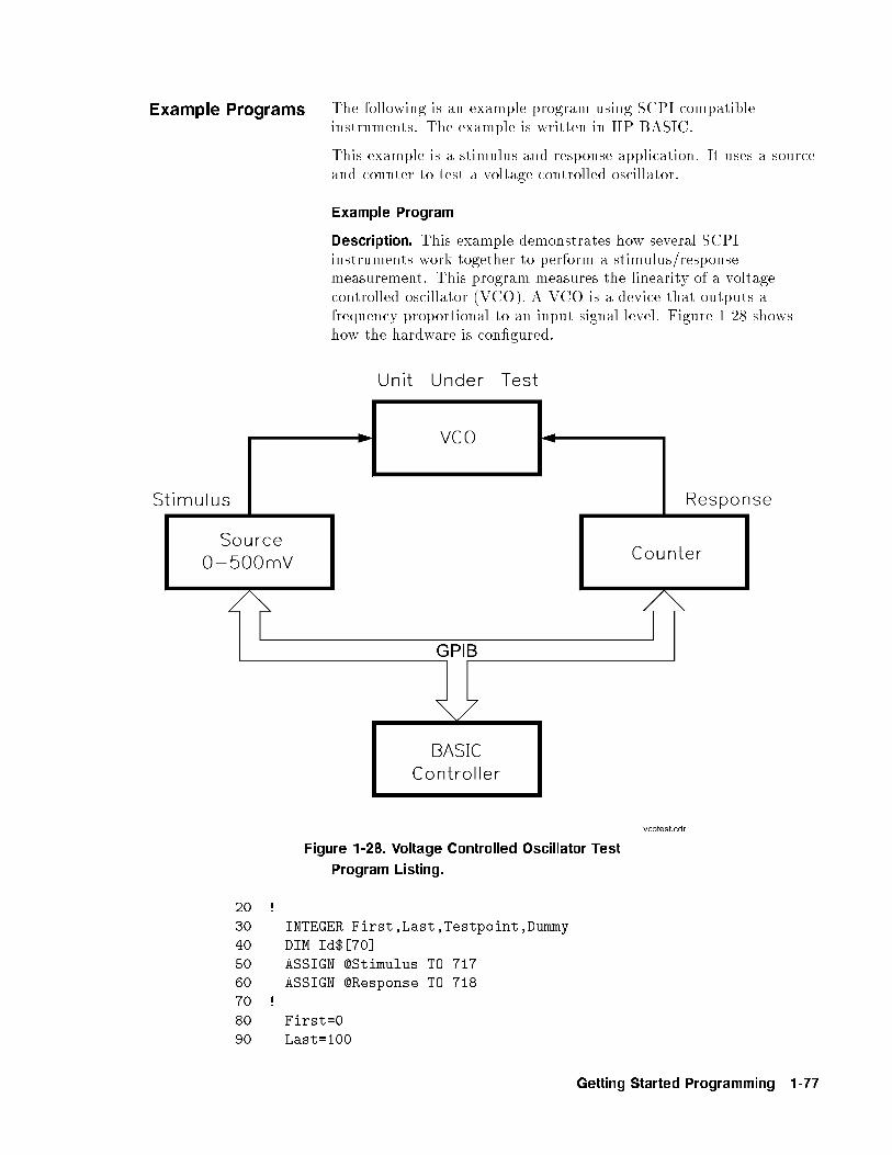
Example Programs The following is an example program using SCPI compatibleinstruments. The example is written in HP BASIC.
This example is a stimulus and response application. It uses a sourceand counter to test a voltage controlled oscillator.
Example Program
Description. This example demonstrates how several SCPIinstruments work together to perform a stimulus/responsemeasurement. This program measures the linearity of a voltagecontrolled oscillator (VCO). A VCO is a device that outputs afrequency proportional to an input signal level. Figure 1-28 showshow the hardware is con�gured.
Figure 1-28. Voltage Controlled Oscillator Test
Program Listing.
20 !
30 INTEGER First,Last,Testpoint,Dummy
40 DIM Id$[70]
50 ASSIGN @Stimulus TO 71760 ASSIGN @Response TO 718
70 !
80 First=0
90 Last=100
Getting Started Programming 1-77
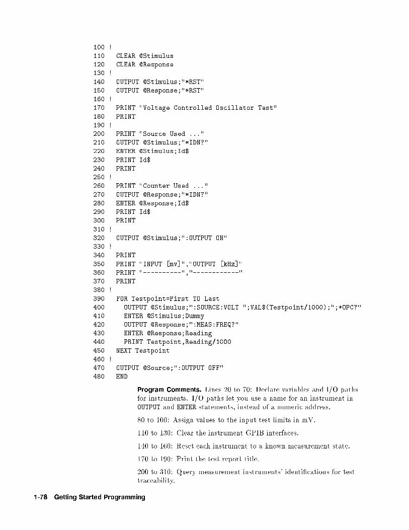
100 !
110 CLEAR @Stimulus
120 CLEAR @Response130 !
140 OUTPUT @Stimulus;"*RST"
150 OUTPUT @Response;"*RST"
160 !
170 PRINT "Voltage Controlled Oscillator Test"
180 PRINT
190 !
200 PRINT "Source Used ..."
210 OUTPUT @Stimulus;"*IDN?"
220 ENTER @Stimulus;Id$
230 PRINT Id$
240 PRINT
250 !
260 PRINT "Counter Used ..."
270 OUTPUT @Response;"*IDN?"
280 ENTER @Response;Id$
290 PRINT Id$
300 PRINT
310 !
320 OUTPUT @Stimulus;":OUTPUT ON"
330 !
340 PRINT
350 PRINT "INPUT [mv]","OUTPUT [kHz]"
360 PRINT "----------","------------"
370 PRINT
380 !
390 FOR Testpoint=First TO Last
400 OUTPUT @Stimulus;":SOURCE:VOLT ";VAL$(Testpoint/1000);";*OPC?"410 ENTER @Stimulus;Dummy
420 OUTPUT @Response;":MEAS:FREQ?"
430 ENTER @Response;Reading
440 PRINT Testpoint,Reading/1000
450 NEXT Testpoint
460 !
470 OUTPUT @Source;":OUTPUT OFF"
480 END
Program Comments. Lines 20 to 70: Declare variables and I/O pathsfor instruments. I/O paths let you use a name for an instrument inOUTPUT and ENTER statements, instead of a numeric address.
80 to 100: Assign values to the input test limits in mV.
110 to 130: Clear the instrument GPIB interfaces.
140 to 160: Reset each instrument to a known measurement state.
170 to 190: Print the test report title.
200 to 310: Query measurement instruments' identi�cations for testtraceability.
1-78 Getting Started Programming

320 to 330: Connect the source output signal to the outputterminals.
340 to 380: Print results table header.
390 to 460: This is the main measurement loop. Line 400 containstwo commands. :SOURce:VOLT sets the output level of the source.*OPC? is used to signal that the preceding command has �nishedexecuting. To make an accurate measurement, the source outputmust be allowed to settle. When the output has settled, *OPC? placesa 1 in the source Output Queue. The program waits at line 410 untilthe 1 returned by *OPC? is entered.
Note that following each OUTPUT containing a query is an ENTER toretrieve the queried value. If you do not use paired OUTPUTs andENTERs, you can overwrite data in the instrument Output Queue andgenerate instrument errors.
470 to 480: Disconnect output terminals of the instruments from theunit under test, and end the program. All HP BASIC programs musthave END as the last statement of the main program.
Getting Started Programming 1-79
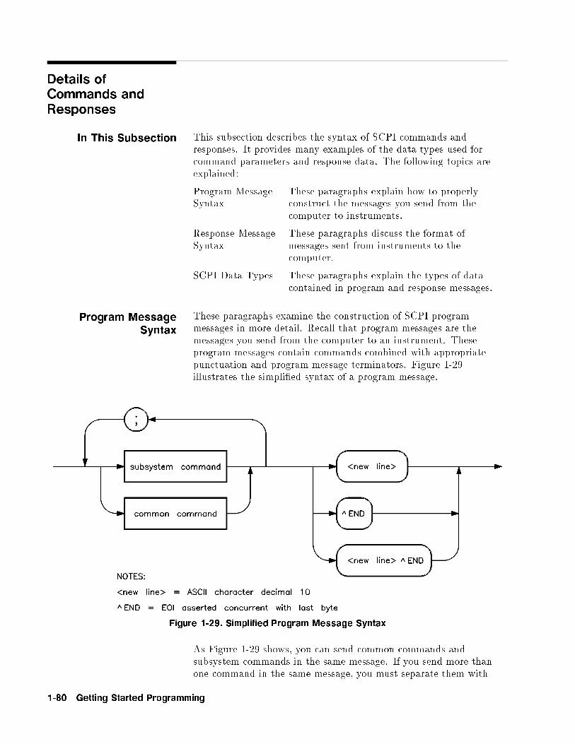
Details ofCommands andResponses
In This Subsection This subsection describes the syntax of SCPI commands andresponses. It provides many examples of the data types used forcommand parameters and response data. The following topics areexplained:
Program MessageSyntax
These paragraphs explain how to properlyconstruct the messages you send from thecomputer to instruments.
Response MessageSyntax
These paragraphs discuss the format ofmessages sent from instruments to thecomputer.
SCPI Data Types These paragraphs explain the types of datacontained in program and response messages.
Program MessageSyntax
These paragraphs examine the construction of SCPI programmessages in more detail. Recall that program messages are themessages you send from the computer to an instrument. Theseprogram messages contain commands combined with appropriatepunctuation and program message terminators. Figure 1-29illustrates the simpli�ed syntax of a program message.
Figure 1-29. Simplified Program Message Syntax
As Figure 1-29 shows, you can send common commands andsubsystem commands in the same message. If you send more thanone command in the same message, you must separate them with
1-80 Getting Started Programming
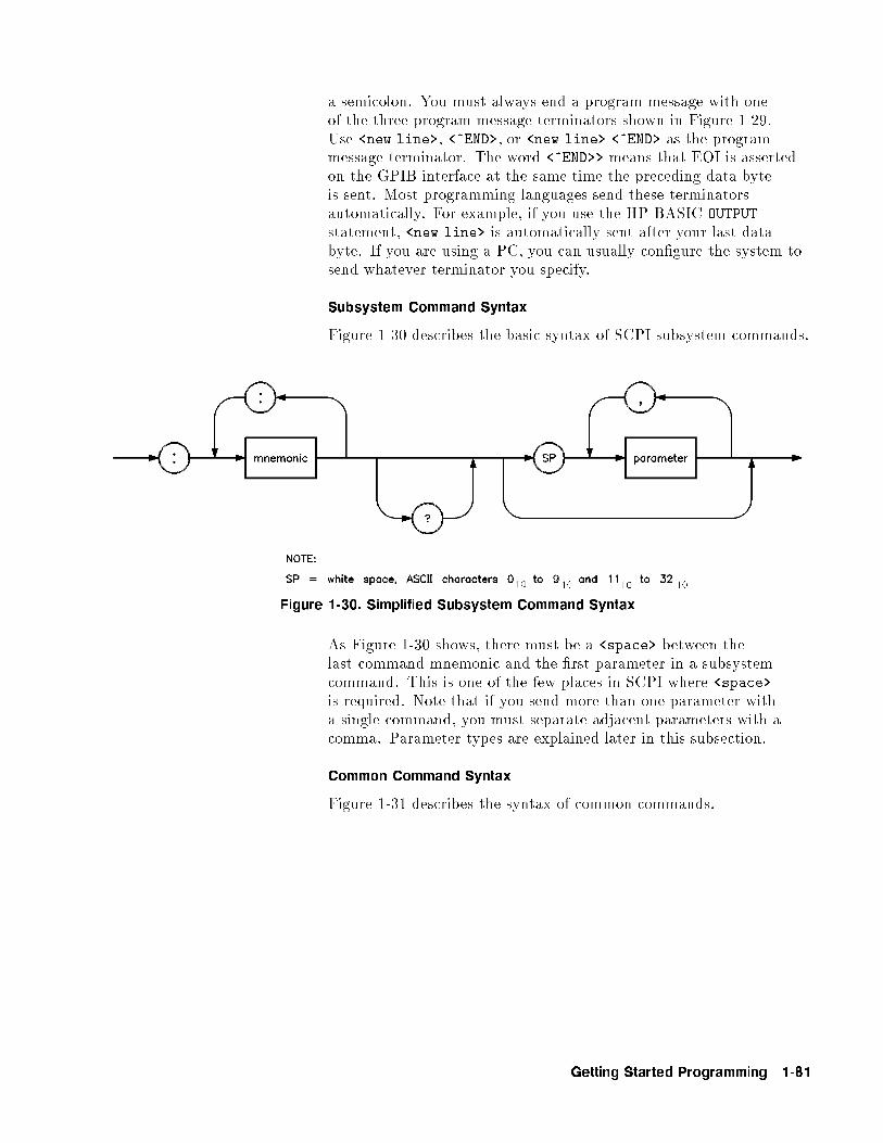
a semicolon. You must always end a program message with oneof the three program message terminators shown in Figure 1-29.Use <new line>, <^END>, or <new line> <^END> as the programmessage terminator. The word <^END>> means that EOI is assertedon the GPIB interface at the same time the preceding data byteis sent. Most programming languages send these terminatorsautomatically. For example, if you use the HP BASIC OUTPUT
statement, <new line> is automatically sent after your last databyte. If you are using a PC, you can usually con�gure the system tosend whatever terminator you specify.
Subsystem Command Syntax
Figure 1-30 describes the basic syntax of SCPI subsystem commands.
Figure 1-30. Simplified Subsystem Command Syntax
As Figure 1-30 shows, there must be a <space> between thelast command mnemonic and the �rst parameter in a subsystemcommand. This is one of the few places in SCPI where <space>is required. Note that if you send more than one parameter witha single command, you must separate adjacent parameters with acomma. Parameter types are explained later in this subsection.
Common Command Syntax
Figure 1-31 describes the syntax of common commands.
Getting Started Programming 1-81
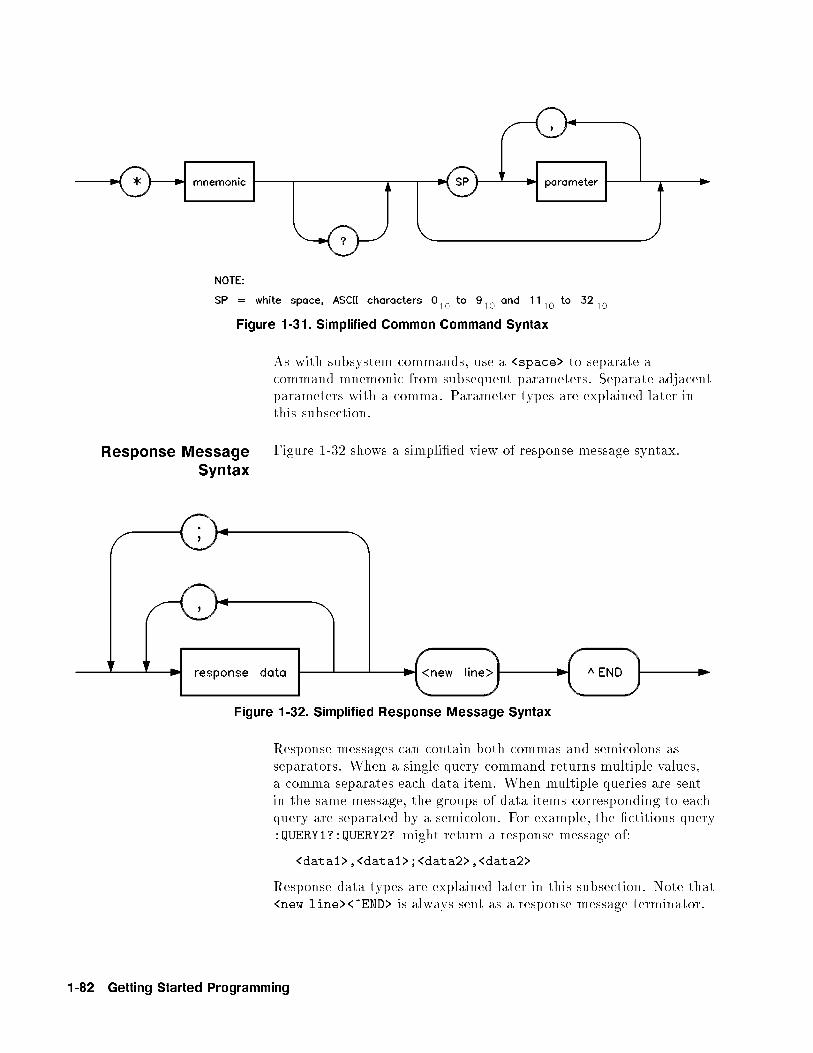
Figure 1-31. Simplified Common Command Syntax
As with subsystem commands, use a <space> to separate acommand mnemonic from subsequent parameters. Separate adjacentparameters with a comma. Parameter types are explained later inthis subsection.
Response MessageSyntax
Figure 1-32 shows a simpli�ed view of response message syntax.
Figure 1-32. Simplified Response Message Syntax
Response messages can contain both commas and semicolons asseparators. When a single query command returns multiple values,a comma separates each data item. When multiple queries are sentin the same message, the groups of data items corresponding to eachquery are separated by a semicolon. For example, the �ctitious query:QUERY1?:QUERY2? might return a response message of:
<data1>,<data1>;<data2>,<data2>
Response data types are explained later in this subsection. Note that<new line><^END> is always sent as a response message terminator.
1-82 Getting Started Programming

SCPI Data Types These paragraphs explain the data types available for parameters andresponse data. They list the types available and present examples foreach type. SCPI de�nes di�erent data formats for use in programmessages and response messages. It does this to accommodatethe principle of forgiving listening and precise talking. Recallthat forgiving listening means instruments are exible, acceptingcommands and parameters in various formats. Precise talking meansan instrument always responds to a particular query in a prede�ned,rigid format. Parameter data types are designed to be exible inthe spirit of forgiving listening. Conversely, response data types arede�ned to meet the requirements of precise talking.
Table 1-3. SCPI Data Types
Parameter Types Response Data Types
Numeric Real or Integer
Extended Numeric Integer
Discrete Discrete
Boolean Numeric Boolean
String String
Block De�nite Length Block
Inde�nite Length Block
Non-decimal Numeric Hexadecimal
Octal
Binary
Notice that each parameter type has one or more correspondingresponse data types. For example, a setting that you program usinga numeric parameter returns either real or integer response datawhen queried. Whether real or integer response data is returneddepends on the instrument used. However, precise talking requiresthat the response data type be clearly de�ned for a particularinstrument and query. The instrument command dictionary generallycontains information about data types for individual commands. Thefollowing paragraphs explain each parameter and response data typein more detail.
Parameter Types
Numeric Parameters. Numeric parameters are used in bothsubsystem commands and common commands. Numeric parametersaccept all commonly used decimal representations of numbersincluding optional signs, decimal points, and scienti�c notation.
If an instrument setting programmed with a numeric parameter canonly assume a �nite number of values, the instrument automatically
Getting Started Programming 1-83
rounds the parameter. For example, if an instrument has aprogrammable output impedance of 50 or 75 ohms, you speci�ed76.1 for output impedance, the value is rounded to 75. If theinstrument setting can only assume integer values, it automaticallyrounds the value to an integer. For example, sending *ESE 10.123
is the same as sending *ESE 10.
Examples of numeric parameters:
100 no decimal point required
100. fractional digits optional
-1.23 leading signs allowed
4.56e<space>3 space allowed after e in exponentials
-7.89E-01 use either E or e in exponentials
+256 leading + allowed
.5 digits left of decimal point optional
Extended Numeric Parameters. Most measurement relatedsubsystems use extended numeric parameters to specify physicalquantities. Extended numeric parameters accept all numericparameter values and other special values as well. All extendednumeric parameters accept MAXimum and MINimum as values. Otherspecial values, such as UP and DOWN may be available as documentedin the instrument's command dictionary. Note that MINimum andMAXimum can be used to set or query values. The query formsare useful for determining the range of values allowed for a givenparameter.
In some instruments, extended numeric parameters acceptengineering unit su�xes as part of the parameter value. Refer to thecommand summary to see if this capability exists.
Note that extended numeric parameters are not used for commoncommands or STATus subsystem commands.
Examples of extended numeric parameters:
100. any simple numeric values
-1.23
4.56e<space>3
-7.89E-01
+256
.5
MAX
largest valid setting
MIN valid setting nearest negative in�nity
-100 mV negative 100 millivolts
1-84 Getting Started Programming
Discrete Parameters. Use discrete parameters to program settingsthat have a �nite number of values. Discrete parameters usemnemonics to represent each valid setting. They have a long anda short form, just like command mnemonics. You can used mixedupper and lower case letters for discrete parameters.
Examples of discrete parameters used with the ROSCillatorsubsystem:
INTernal internal frequency standard
EXTernal external frequency standard
NONE no frequency standard, free run mode
Although discrete parameters values look like command keywords,do not confuse the two. In particular, be sure to use colons andspaces properly. Use a colon to separate command mnemonics fromeach other. Use a space to separate parameters from commandmnemonics.
Boolean Parameters. Boolean parameters represent a single binarycondition that is either true or false. There are only four possiblevalues for a Boolean parameter.
Examples of Boolean parameters:
ON Boolean TRUE, upper/lower case allowed
OFF Boolean FALSE, upper/lower case allowed
1 Boolean TRUE
0 Boolean FALSE
Response Data Types
Real Response Data. A large portion of all measurement data areformatted as real response data. Real response data are decimalnumbers in either �xed decimal notation or scienti�c notation. Ingeneral, you do not need to worry about the rules for formattingreal data, or whether �xed decimal or scienti�c notation is used.Most high level programming languages that support instrument I/Ohandle either type transparently.
Examples of real response data:
1.23E+0
-1.0E+2
+1.0E+2
0.5E+0
1.23
-100.0
+100.0
0.5
Getting Started Programming 1-85
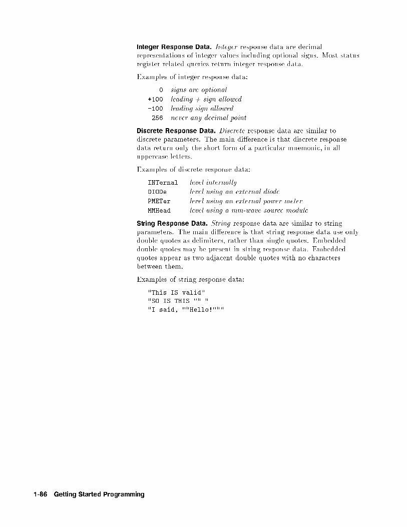
Integer Response Data. Integer response data are decimalrepresentations of integer values including optional signs. Most statusregister related queries return integer response data.
Examples of integer response data:
0 signs are optional
+100 leading + sign allowed
-100 leading sign allowed
256 never any decimal point
Discrete Response Data. Discrete response data are similar todiscrete parameters. The main di�erence is that discrete responsedata return only the short form of a particular mnemonic, in alluppercase letters.
Examples of discrete response data:
INTernal level internally
DIODe level using an external diode
PMETer level using an external power meter
MMHead level using a mm-wave source module
String Response Data. String response data are similar to stringparameters. The main di�erence is that string response data use onlydouble quotes as delimiters, rather than single quotes. Embeddeddouble quotes may be present in string response data. Embeddedquotes appear as two adjacent double quotes with no charactersbetween them.
Examples of string response data:
"This IS valid""SO IS THIS "" "
"I said, ""Hello!"""
1-86 Getting Started Programming
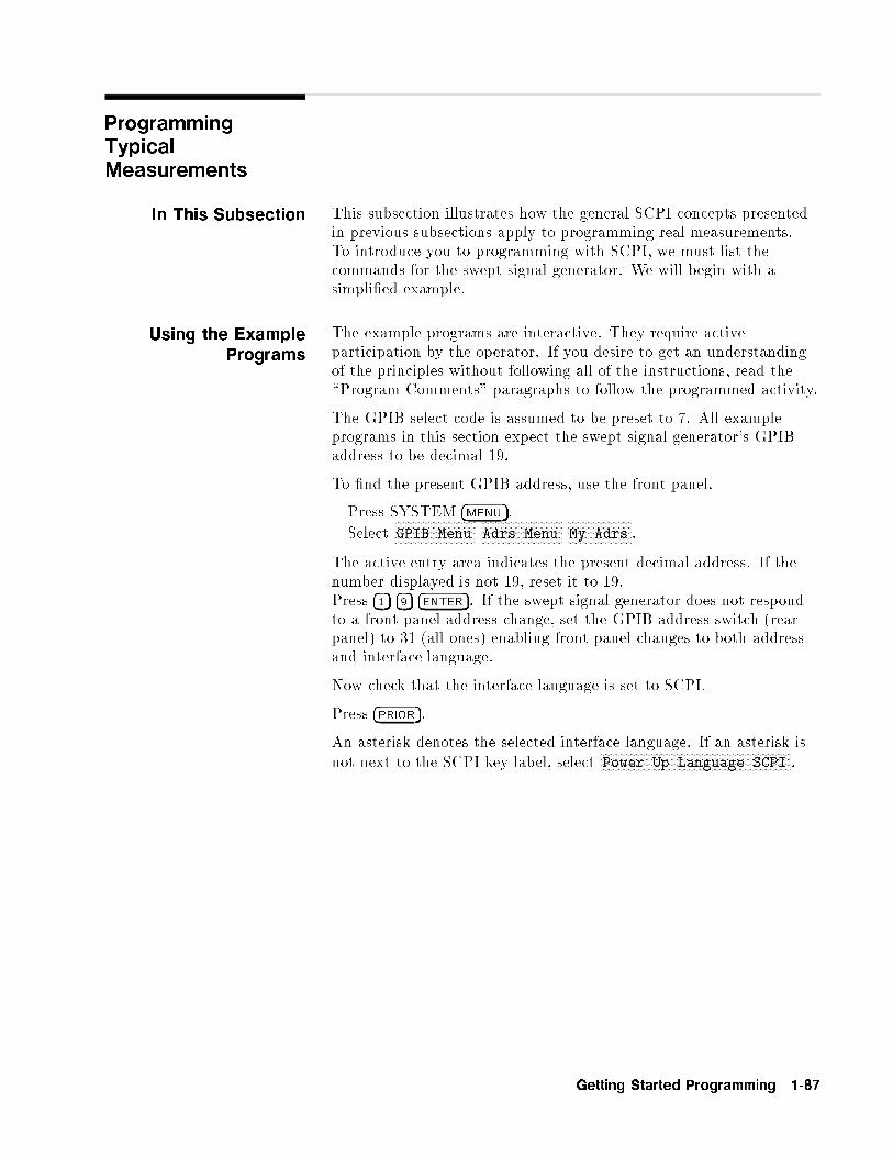
ProgrammingTypicalMeasurements
In This Subsection This subsection illustrates how the general SCPI concepts presentedin previous subsections apply to programming real measurements.To introduce you to programming with SCPI, we must list thecommands for the swept signal generator. We will begin with asimpli�ed example.
Using the ExamplePrograms
The example programs are interactive. They require activeparticipation by the operator. If you desire to get an understandingof the principles without following all of the instructions, read the\Program Comments" paragraphs to follow the programmed activity.
The GPIB select code is assumed to be preset to 7. All exampleprograms in this section expect the swept signal generator's GPIBaddress to be decimal 19.
To �nd the present GPIB address, use the front panel.
Press SYSTEM �MENU�.
SelectNNNNNNNNNNNNNNNNNNNNNNNNNNNNNGPIB Menu
NNNNNNNNNNNNNNNNNNNNNNNNNNNNNAdrs Menu
NNNNNNNNNNNNNNNNNNNNNNNMy Adrs .
The active entry area indicates the present decimal address. If thenumber displayed is not 19, reset it to 19.Press �1� �9� �ENTER�. If the swept signal generator does not respondto a front panel address change, set the GPIB address switch (rearpanel) to 31 (all ones) enabling front panel changes to both addressand interface language.
Now check that the interface language is set to SCPI.
Press �PRIOR�.
An asterisk denotes the selected interface language. If an asterisk isnot next to the SCPI key label, select
NNNNNNNNNNNNNNNNNNNNNNNNNNNNNNNNNNNNNNNNNNNNNNNNNNNNNNNNNNNNNNNNNNNNPower Up Language SCPI .
Getting Started Programming 1-87
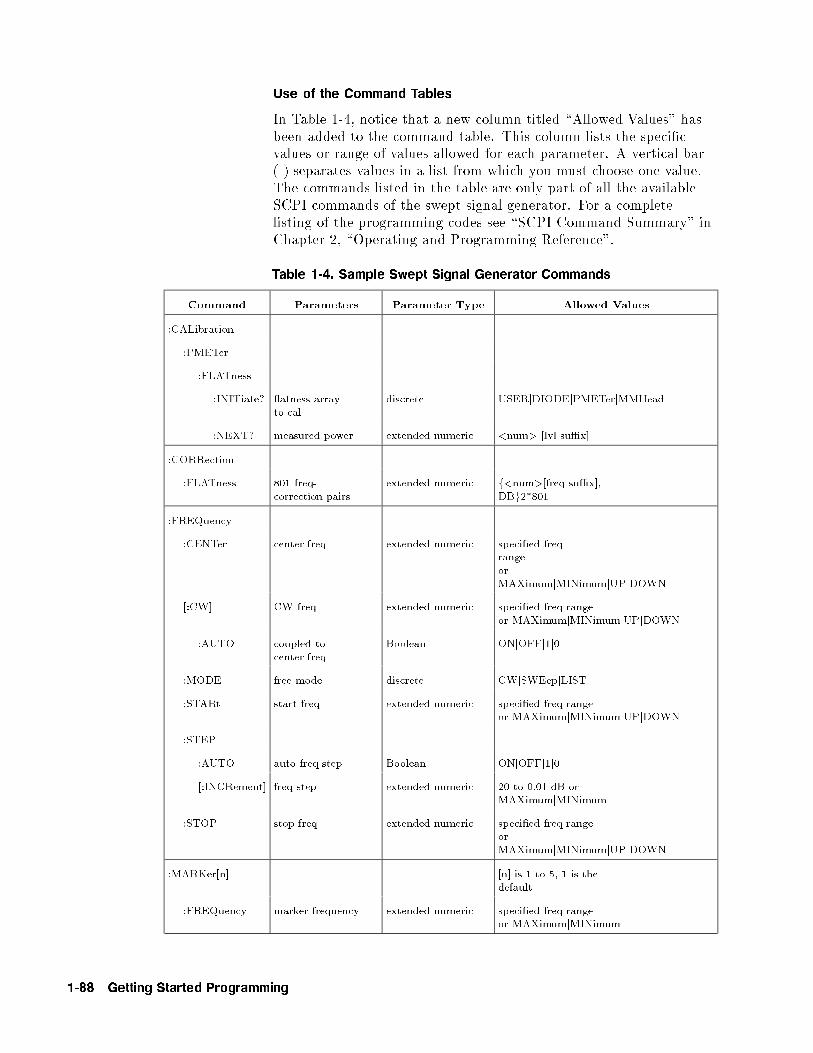
Use of the Command Tables
In Table 1-4, notice that a new column titled \Allowed Values" hasbeen added to the command table. This column lists the speci�cvalues or range of values allowed for each parameter. A vertical bar(j) separates values in a list from which you must choose one value.The commands listed in the table are only part of all the availableSCPI commands of the swept signal generator. For a completelisting of the programming codes see \SCPI Command Summary" inChapter 2, \Operating and Programming Reference".
Table 1-4. Sample Swept Signal Generator Commands
Command Parameters Parameter Type Allowed Values
:CALibration
:PMETer
:FLATness
:INITiate? atness arrayto cal
discrete USERjDIODEjPMETerjMMHead
:NEXT? measured power extended numeric <num> [lvl su�x]
:CORRection
:FLATness 801 freq-correction pairs
extended numeric f<num>[freq su�x],DBg2*801
:FREQuency
:CENTer center freq extended numeric speci�ed freqrangeorMAXimumjMINimumjUPjDOWN
[:CW] CW freq extended numeric speci�ed freq rangeor MAXimumjMINimumjUPjDOWN
:AUTO coupled tocenter freq
Boolean ONjOFFj1j0
:MODE free mode discrete CWjSWEepjLIST
:STARt start freq extended numeric speci�ed freq rangeor MAXimumjMINimumjUPjDOWN
:STEP
:AUTO auto freq step Boolean ONjOFFj1j0
[:INCRement] freq step extended numeric 20 to 0.01 dB orMAXimumjMINimum
:STOP stop freq extended numeric speci�ed freq rangeorMAXimumjMINimumjUPjDOWN
:MARKer[n] [n] is 1 to 5, 1 is thedefault
:FREQuency marker frequency extended numeric speci�ed freq rangeor MAXimumjMINimum
1-88 Getting Started Programming
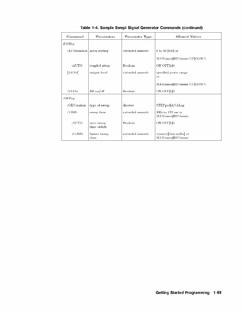
Table 1-4. Sample Swept Signal Generator Commands (continued)
Command Parameters Parameter Type Allowed Values
:POWer
:ATTenuation atten setting extended numeric 0 to 90 [DB] or
MAXimumjMINimumjUPjDOWN
:AUTO coupled atten Boolean ONjOFFj1j0
[:LEVel] output level extended numeric speci�ed power rangeor
MAXimumjMINimumjUPjDOWN
:STATe RF on/o� Boolean ONjOFFj1j0
:SWEep
:GENeration type of sweep discrete STEPpedjANALog
:TIME sweep time extended numeric 200s to 133 ms orMAXimumjMINimum
:AUTO auto sweeptime switch
Boolean ONjOFFj1j0
:LLIMit fastest sweeptime
extended numeric <num>[time su�x] orMAXimumjMINimum
Getting Started Programming 1-89

GPIB Check, ExampleProgram 1
This �rst program is to verify that the GPIB connections andinterface are functional. Connect a controller to the swept signalgenerator via a GPIB cable. Clear and reset the controller and typein the following program:
10 Source=719
20 ABORT 7
30 LOCAL Source
40 CLEAR Source50 REMOTE Source
60 CLS
70 PRINT "The source should now be in REMOTE."
80 PRINT "Verify that the 'REMOTE' LED is on."
90 END
Run the program and verify that the REMOTE LED is lit on theswept signal generator. If it is not, verify that the swept signalgenerator address is set to 19 and that the interface cable is properlyconnected.
If the controller display indicates an error message, it is possible thatthe program was entered in incorrectly. If the controller acceptsthe REMOTE statement but the swept signal generator REMOTELED does not turn on, perform the operational checks as outlined inthe respective Operating and Service Manuals to �nd the defectivedevice.
Program Comments
10: Set up a variable to contain the GPIB address of the source.
20: Abort any bus activity and return the GPIB interfaces to theirreset states.
30: Place the source into LOCAL to cancel any Local Lockoutsthat may have been set up.
40: Reset the source's parser and clear any pending output fromthe source. Prepare the source to receive new commands.
50: Place the source into REMOTE.
60: Clear the display of the computer.
70: Print a message to the computer's display.
1-90 Getting Started Programming
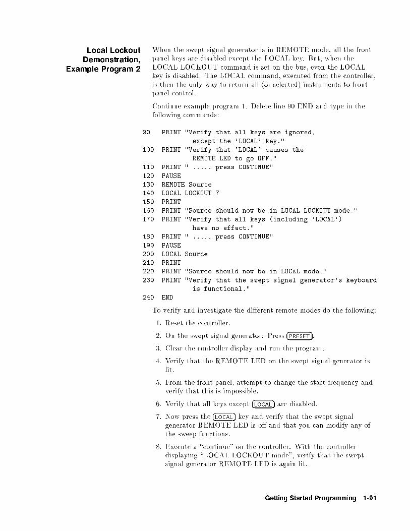
Local LockoutDemonstration,
Example Program 2
When the swept signal generator is in REMOTE mode, all the frontpanel keys are disabled except the LOCAL key. But, when theLOCAL LOCKOUT command is set on the bus, even the LOCALkey is disabled. The LOCAL command, executed from the controller,is then the only way to return all (or selected) instruments to frontpanel control.
Continue example program 1. Delete line 90 END and type in thefollowing commands:
90 PRINT "Verify that all keys are ignored,
except the 'LOCAL' key."
100 PRINT "Verify that 'LOCAL' causes the
REMOTE LED to go OFF."
110 PRINT " ..... press CONTINUE"
120 PAUSE
130 REMOTE Source
140 LOCAL LOCKOUT 7
150 PRINT
160 PRINT "Source should now be in LOCAL LOCKOUT mode."
170 PRINT "Verify that all keys (including 'LOCAL')
have no effect."
180 PRINT " ..... press CONTINUE"
190 PAUSE
200 LOCAL Source
210 PRINT
220 PRINT "Source should now be in LOCAL mode."
230 PRINT "Verify that the swept signal generator's keyboard
is functional."
240 END
To verify and investigate the di�erent remote modes do the following:
1. Reset the controller.
2. On the swept signal generator: Press �PRESET�.
3. Clear the controller display and run the program.
4. Verify that the REMOTE LED on the swept signal generator islit.
5. From the front panel, attempt to change the start frequency andverify that this is impossible.
6. Verify that all keys except �LOCAL� are disabled.
7. Now press the �LOCAL� key and verify that the swept signalgenerator REMOTE LED is o� and that you can modify any ofthe sweep functions.
8. Execute a \continue" on the controller. With the controllerdisplaying \LOCAL LOCKOUT mode", verify that the sweptsignal generator REMOTE LED is again lit.
Getting Started Programming 1-91

9. Attempt to change the start frequency and press �PRESET�. Verifythat this is impossible.
10. Now press the swept signal generator �LOCAL� key and verify thatstill no action is taken.
11. Execute a \continue" on the controller. With the controllerdisplaying \LOCAL mode", verify that the swept signalgenerator REMOTE LED is o�. Also verify that all sweepfunctions now can be modi�ed via the front panel controls.
HINT Note that the swept signal generator �LOCAL� key produces the sameresult as programming LOCAL 719 or LOCAL 7. Be careful becausethe LOCAL 7 command places all instruments on the GPIB in thelocal state as opposed to just the swept signal generator.
Program Comments
90 to 120: Print a message on the computer's display, then pause.
130: Place the source into REMOTE.
140: Place the source into LOCAL LOCKOUT mode.
150 to 190: Print a message on the computer's display, then pause.
200: Return the source to local control.
210 to 230: Print a message on the computer's display.
1-92 Getting Started Programming
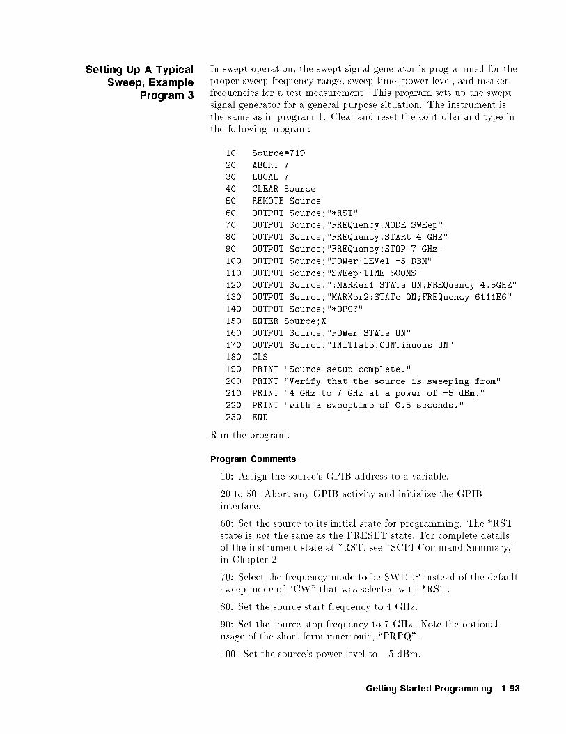
Setting Up A TypicalSweep, Example
Program 3
In swept operation, the swept signal generator is programmed for theproper sweep frequency range, sweep time, power level, and markerfrequencies for a test measurement. This program sets up the sweptsignal generator for a general purpose situation. The instrument isthe same as in program 1. Clear and reset the controller and type inthe following program:
10 Source=719
20 ABORT 730 LOCAL 7
40 CLEAR Source
50 REMOTE Source
60 OUTPUT Source;"*RST"
70 OUTPUT Source;"FREQuency:MODE SWEep"
80 OUTPUT Source;"FREQuency:STARt 4 GHZ"
90 OUTPUT Source;"FREQuency:STOP 7 GHz"
100 OUTPUT Source;"POWer:LEVel -5 DBM"
110 OUTPUT Source;"SWEep:TIME 500MS"
120 OUTPUT Source;":MARKer1:STATe ON;FREQuency 4.5GHZ"
130 OUTPUT Source;"MARKer2:STATe ON;FREQuency 6111E6"
140 OUTPUT Source;"*OPC?"
150 ENTER Source;X
160 OUTPUT Source;"POWer:STATe ON"
170 OUTPUT Source;"INITIate:CONTinuous ON"
180 CLS
190 PRINT "Source setup complete."
200 PRINT "Verify that the source is sweeping from"
210 PRINT "4 GHz to 7 GHz at a power of -5 dBm,"
220 PRINT "with a sweeptime of 0.5 seconds."
230 END
Run the program.
Program Comments
10: Assign the source's GPIB address to a variable.
20 to 50: Abort any GPIB activity and initialize the GPIBinterface.
60: Set the source to its initial state for programming. The *RSTstate is not the same as the PRESET state. For complete detailsof the instrument state at *RST, see \SCPI Command Summary,"in Chapter 2.
70: Select the frequency mode to be SWEEP instead of the defaultsweep mode of \CW" that was selected with *RST.
80: Set the source start frequency to 4 GHz.
90: Set the source stop frequency to 7 GHz. Note the optionalusage of the short-form mnemonic, \FREQ".
100: Set the source's power level to �5 dBm.
Getting Started Programming 1-93

110: Set the sweeptime to 500 ms. Notice that upper/lower case incommands does not matter. Also spaces before the su�x (\MS")are not required in SCPI.
120 and 130: Set markers 1 and 2 to a �xed value. Notice that thevalue for marker 2 does not end with a frequency su�x. Hertz is adefault terminator and is understood.
140: Wait until the source has completed setting up the commandsthat have been sent so far before turning on the output.
150: The ENTER statement causes the program to wait here untilthe source responds to the previous *OPC? with a '1'.
160: The source has now completed processing the commands.The RF frequency, power, and markers are at their programmedvalues. Turn on the RF output of the source.
170: Select a continuously initiated sweep instead of the defaultmode of non-continuous that was selected with *RST.
180: Clear the computer's display.
190 to 220: Print a message on the computer's display.
1-94 Getting Started Programming
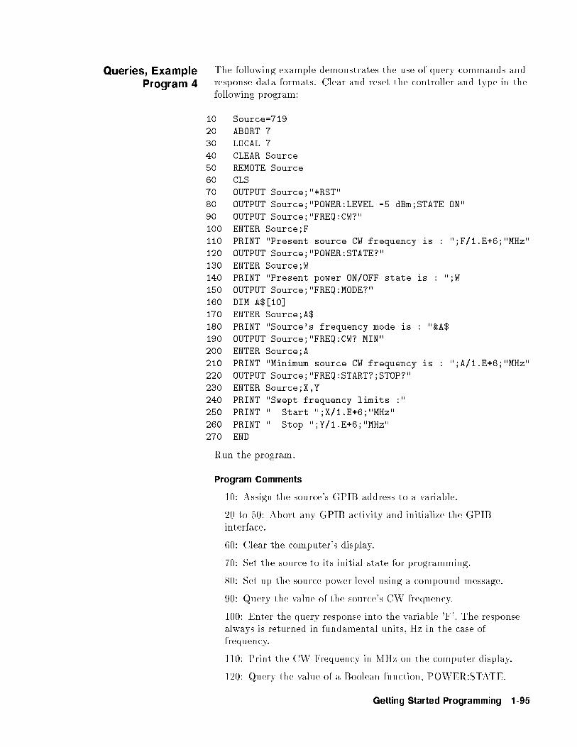
Queries, ExampleProgram 4
The following example demonstrates the use of query commands andresponse data formats. Clear and reset the controller and type in thefollowing program:
10 Source=719
20 ABORT 7
30 LOCAL 7
40 CLEAR Source
50 REMOTE Source60 CLS
70 OUTPUT Source;"*RST"
80 OUTPUT Source;"POWER:LEVEL -5 dBm;STATE ON"
90 OUTPUT Source;"FREQ:CW?"
100 ENTER Source;F
110 PRINT "Present source CW frequency is : ";F/1.E+6;"MHz"
120 OUTPUT Source;"POWER:STATE?"
130 ENTER Source;W
140 PRINT "Present power ON/OFF state is : ";W
150 OUTPUT Source;"FREQ:MODE?"
160 DIM A$[10]
170 ENTER Source;A$
180 PRINT "Source's frequency mode is : "&A$
190 OUTPUT Source;"FREQ:CW? MIN"
200 ENTER Source;A
210 PRINT "Minimum source CW frequency is : ";A/1.E+6;"MHz"
220 OUTPUT Source;"FREQ:START?;STOP?"
230 ENTER Source;X,Y
240 PRINT "Swept frequency limits :"
250 PRINT " Start ";X/1.E+6;"MHz"
260 PRINT " Stop ";Y/1.E+6;"MHz"
270 END
Run the program.
Program Comments
10: Assign the source's GPIB address to a variable.
20 to 50: Abort any GPIB activity and initialize the GPIBinterface.
60: Clear the computer's display.
70: Set the source to its initial state for programming.
80: Set up the source power level using a compound message.
90: Query the value of the source's CW frequency.
100: Enter the query response into the variable 'F'. The responsealways is returned in fundamental units, Hz in the case offrequency.
110: Print the CW Frequency in MHz on the computer display.
120: Query the value of a Boolean function, POWER:STATE.
Getting Started Programming 1-95
130: Enter the query response into a variable 'W'. Booleanresponses are always '1' for ON and '0' for OFF.
140: Print the value of the POWER:STATE on the computerdisplay.
150: Query the value of a discrete function (FREQ:MODE).
160: Dimension a string variable to contain the response.
170: Enter the response into A$. The response will be a stringthat represents the function's present value.
180: Print the value of A$ on the computer display.
190: Example usage of a MIN query. This will request themaximum value that the FREQ:CW function can be programmedto.
200: Enter the numeric response into the variable A.
210: Print the value of A on the computer display.
220: This is compound query. Up to 8 parameters can be queriedfrom the swept signal generator at one time using this method. Inthis example, the start and stop frequencies are interrogated.
230: The responses are read back into the variables X and Y. Theorder of the responses is the same as the order of the queries. Xwill contain the START frequency and Y will contain the STOP.
240 to 260: Print the START/STOP frequencies on the display.
1-96 Getting Started Programming

Saving and RecallingStates, Example
Program 5
When a typical sweep, like example program 3, is set up, thecomplete front panel state may be saved for later use in non-volatilememories called registers 1 through 8. This can be done remotely asa part of a program. Clear and reset the controller and type in thefollowing program:
10 Source=719
20 ABORT 7
30 LOCAL 740 CLEAR Source
50 REMOTE Source
60 CLS
70 OUTPUT Source;"*RST;FREQ:MODE SWE;STAR 4GHZ
;STOP 5GHZ;:INIT:CONT ON"
80 OUTPUT Source;"*SAV 1"
90 CLS
100 PRINT "A sweeping state has been saved in REGISTER 1."
110 OUTPUT Source;"*RST;FREQ:CW 1.23456GHZ;:POW:LEV -1DBM"
120 OUTPUT Source;"*SAV 2"
130 PRINT "A CW state has been saved in REGISTER 2."
140 PRINT "..... Press Continue"
150 PAUSE
160 OUTPUT Source;"*RCL 1"
170 PRINT "Register 1 recalled. Verify source is sweeping."
180 PRINT "Press Continue."
190 PAUSE
200 OUTPUT Source;"*RCL 2"
210 PRINT "Register 2 recalled."
220 PRINT "Verify source is in CW mode."
230 END
Run the program.
Program Comments
10: Assign the source's GPIB address to a variable.
20 to 50: Abort any GPIB activity and initialize the GPIBinterface.
60: Clear the computer's display.
70: Set up the source for a sweeping state. Note the combinationof several commands into a single message. This single line isequivalent to the following lines:
OUTPUT Source;"*RST"
OUTPUT Source;"FREQ:MODE SWEep"
OUTPUT Source;"FREQ:STARt 4 GHZ"
OUTPUT Source;"FREQ:STOP 5 GHZ"
OUTPUT Source;"INIT:CONT ON"
80: Save this state into storage register 1.
Getting Started Programming 1-97

90: Clear the computer display.
100: Print a message on the computer display.
110: Set up the source for a CW state. Note the combinationof several commands into a single message. This single line isequivalent to the following lines:
OUTPUT Source;"*RST"
OUTPUT Source;"FREQ:CW 1.23456 GHZ"OUTPUT Source;"POWer:LEVel -1 DBM"
120: Save this state into storage register 2.
130 to 150: Print a message on the computer display and pause.
160: Recall the instrument state from register 1. It should containthe sweeping state.
170 to 190: Print a message on the computer display and pause.
200: Recall the instrument state from register 2. It should containthe CW state.
210 and 220: Print messages on the computer display.
1-98 Getting Started Programming

Looping andSynchronization,
Example Program 6
Clear and reset the controller and type in the following program:
10 Source=719
20 ABORT 7
30 LOCAL 7
40 CLEAR Source
50 REMOTE Source
60 CLS
70 OUTPUT Source;"*RST"
80 OUTPUT Source;"FREQ:START 4 GHZ; STOP 5 GHZ; MODE SWEEP"
90 OUTPUT Source;"POWER:LEVEL -1 DBM; STATE ON"
100 OUTPUT Source;"SWEEP:TIME 1"
110 OUTPUT Source;"*OPC?"
120 ENTER Source;X
130 REPEAT
140 DISP "Enter number of sweeps to take : [0 to exit]";
150 INPUT N
160 IF N>0 THEN
170 FOR I=1 TO N
180 DISP "Taking sweep number : ";I
190 OUTPUT Source;"INIT:IMM;*OPC?"
200 ENTER \210 NEXT I
220 END IF
230 UNTIL N=0
240 END
Run the program.
Program Comments
10: Assign the source's GPIB address to a variable.
20 to 50: Abort any GPIB activity and initialize the GPIBinterface.
60: Clear the computer's display.
70: Set the source to its initial state for programming.
80: Set up the frequency parameters using a compound message.
90: Set up the source's power level and state using a compoundmessage.
100: Set up the source's sweep time to 1 second.
110: Send the *OPC? command to the source to ensure that theprevious commands are completed and the source is ready to begincontrolled sweeps.
120: Enter the response to the *OPC? into the variable X. Theresponse should be a '1'.
130: Start of the loop.
Getting Started Programming 1-99

140 and 150: Prompt the operator for the number of sweeps totake. The number of sweeps to take is stored in the variable N.Enter 0 to quit the program.
160: Don't take any sweeps if N is less than 0.
170: Start a FOR/NEXT loop to take N sweeps.
180: Display the number of this sweep on the computer display.
190: Initiate a single sweep on the source and then wait untilthe pending operation is complete. Return a '1' when the sweepcompletes.
200: Enter the response to the *OPC? into the variable X. Theprogram execution will halt on this ENTER statement until thesweep is �nished.
210: Repeat the INIT:IMM sequence N times.
220: End of the IF statement to skip sweeps if N is negative.
230: Exit the program if the value of N is 0.
1-100 Getting Started Programming
Using the *WAICommand, Example
Program 7
The following example illustrates the use of the *WAI command tocause the swept signal generator to perform a synchronous sweep.
10 Source=719
20 ABORT 7
30 LOCAL 7
40 CLEAR Source
50 REMOTE Source
60 CLS
70 OUTPUT Source;"*RST"
80 OUTPUT Source;"FREQ:STAR 4GHZ; STOP 5GHZ; MODE SWE"
90 OUTPUT Source;"SWE:TIME 2"
100 OUTPUT Source;"*OPC?"
110 ENTER Source;X
120 FOR I=1 TO 4
130 OUTPUT Source;"INIT"
140 OUTPUT Source;"*WAI"
150 OUTPUT Source;"POW:STAT ON"
160 OUTPUT Source;"INIT"
170 OUTPUT Source;"*WAI"
180 OUTPUT Source;"POW:STAT OFF"
190 NEXT I
200 PRINT "Finished sending commands to source."210 PRINT "Note that execution is continuing for four cycles."
220 END
Run the program.
Program Comments
10: Assign the source's GPIB address to a variable.
20 to 50: Abort any GPIB activity and initialize the GPIBinterface.
60: Clear the computer's display.
70: Set the source to its initial state for programming.
80: Set the source up for a sweep, from 4 GHz to 5 GHz.
90: Set the sweep time to 2 seconds. In SCPI, su�xes are optionalif you program in fundamental units (for sweep time, that wouldbe seconds).
100: Send an *OPC? to the source.
110: Enter the query response to the *OPC? into a variable \X".The program execution will halt here until the source has �nishedprocessing all the commands up to this point. Once complete, thesource will respond to the *OPC? with a \1".
120: Begin a FOR/NEXT loop that is repeated four times.
130: Initiate a sweep on the source.
Getting Started Programming 1-101

140: Send a *WAI command to the source. This commandcauses the source to stop executing new commands until all priorcommands and operations have completed execution. In this case,there is a sweep in progress, so no further commands will beexecuted until the sweep �nishes.
150: Turn the RF output of the source ON.
160: Initiate a sweep on the source.
170: Send another *WAI to the source. Although the *WAIcommand causes EXECUTION of commands to be held o�, ithas no e�ect on the transfer of commands over the GPIB. Thecommands continue to be accepted by the source and are bu�ereduntil they can be executed.
180: Toggle the RF STATE to OFF.
190: Repeat the sample exercise.
200 and 210: Print messages on the computer display.
1-102 Getting Started Programming

Using the User FlatnessCorrection Commands,
Example Program 8
The following program interrogates the swept signal generator and anHP/Agilent 437B power meter for frequency and power informationrespectively. The swept signal generator is programmed to sweepfrom 2 to 20 GHz, with frequency-correction pairs every 100 MHzand +5 dBm leveled output power. For this example, we assumethat the path losses do not exceed 5 dBm and that the HP/Agilent437B power meter already has its power sensor's calibration factorsstored in sensor data table 0. If another power meter is used, thepower sensor's calibration factors will have to be stored in a look-uptable. Modify the program to suit your particular measurementrequirements. Up to 801 points may be entered in the user atnesscorrection table with this program.
SCPI commands are used to set up the source parameters and entercorrection frequencies and data into the correction table.
10 !ASSIGN THE ADDRESS TO THE SOURCE AND POWER METER
20 DIM A$[5000],B$[5000]
30 ASSIGN @Source TO 719
40 ASSIGN @Meter TO 713
50 INTEGER Error_flag
60 ABORT 7
70 !
80 !SET UP SOURCE
90 OUTPUT @Source;"*RST"
100 OUTPUT @Source;"FREQ:MODE SWE;STAR 2 GHZ;STOP 20 GHZ"
110 OUTPUT @Source;"SWEEP:TIME 200 MS"
120 OUTPUT @Source;"POW:LEV 5 DBM;:INIT:CONT ON"
130 OUTPUT @Source;"*OPC?"
140 ENTER @Source;Done
150 !
160 !SET UP POWER METER
170 OUTPUT @Meter;"PR"
180 OUTPUT @Meter;"FA"
190 OUTPUT @Meter;"TR0"
200 !
210 !ZERO POWER METER220 OUTPUT @Source;"POW:STAT OFF"
230 Zero_meter(@Meter,@Source,Error_flag)
240 IF Error_flag THEN
250 BEEP
260 CLEAR SCREEN
270 PRINT "ERROR:METER DID NOT COMPLETE ZEROING OPERATION!"
280 ELSE
290 !
300 !SET UP CORRECTION FREQUENCIES IN USER FLATNESS CORRECTION TABLE
310 !OUTPUT @Source;"CORR:FLAT ";
320 Start_freq=2
330 Stop_freq=20
340 Increment=1
350 N=(((Stop_freq-Start_freq)/Increment)+1)
Getting Started Programming 1-103

360 Freq=Start_freq
370 FOR I=1 TO N
380 A$=A$&VAL$(Freq)&"GHZ,0db,"390 Freq=Freq+Increment
400 NEXT I
410 B=LEN(A$)
420 B=B-1
430 B$=A$[1,B]
440 OUTPUT @Source;"CORR:FLAT ";B$
450 ! OUTPUT @Source;"POW:STAT ON"
460 !
470 !ENTER DATA IN USER CORRECTION TABLE
480 OUTPUT @Source;"CAL:PMET:FLAT:INIT? USER"
490 ENTER @Source;Freq
500 WHILE Freq>0
510 Power=FNRead_meter(@Meter,Freq)
520 OUTPUT @Source;"CAL:PMET:FLAT:NEXT? ";VAL$(Power);"DBM"
530 ENTER @Source;Freq
540 END WHILE
550 END IF
560 END
570 !
580 SUB Zero_meter(@Meter,@Source,INTEGER Error_flag)
590 OUTPUT @Source;"Pow:stat off"
600 OUTPUT @Meter;"CS"
610 OUTPUT @Meter;"ZE"
620 Max_attempts=30
630 Attempts=0
640 Zeroing=1590
650 Finished=0
660 WHILE Zeroing AND NOT Finished670 Attempts=Attempts+1
680 Meter_stat=SPOLL(@Meter)
690 IF Attrmpts>Max_attempts THEN Zeroing=0
700 IF BIT(Meter_stat,1) THEN Finished=1
710 WAIT 1
720 END WHILE
730 OUTPUT @Source;"Pow:stat on"
740 IF NOT Zeroing THEN
750 Error_flag=1
760 ELSE
770 Error_flag=0
780 END IF
790 SUBEND
800 !
810 DEF FNRead_meter(@Meter,Freq)
820 OUTPUT @Meter;"SE0EN"
830 Freq$=VAL$(Freq)
840 OUTPUT @Meter;"FR"&Freq$&"GZ"
850 OUTPUT @Meter;"TR2"
860 ENTER @Meter;Power$
1-104 Getting Started Programming
870 P0=VAL(Power$)
880 Flips=0
890 Slope=0900 REPEAT
910 OUTPUT @Meter;"TR2"
920 ENTER @Meter;Power$
930 P1=VAL(Power$)
940 Slope2=SGN(P0-P1)
950 IF Slope2Slope THEN
960 Flips=Flips+1
970 Slope2=Slope
980 ELSE
990 IF Slope2=0 THEN Flips=Flips+.2
1000 END IF
1010 P0=P1
1020 UNTIL Flips>=3
1030 Power=(P0+P1)/2
1040 RETURN Power
1050 FNEND
Getting Started Programming 1-105
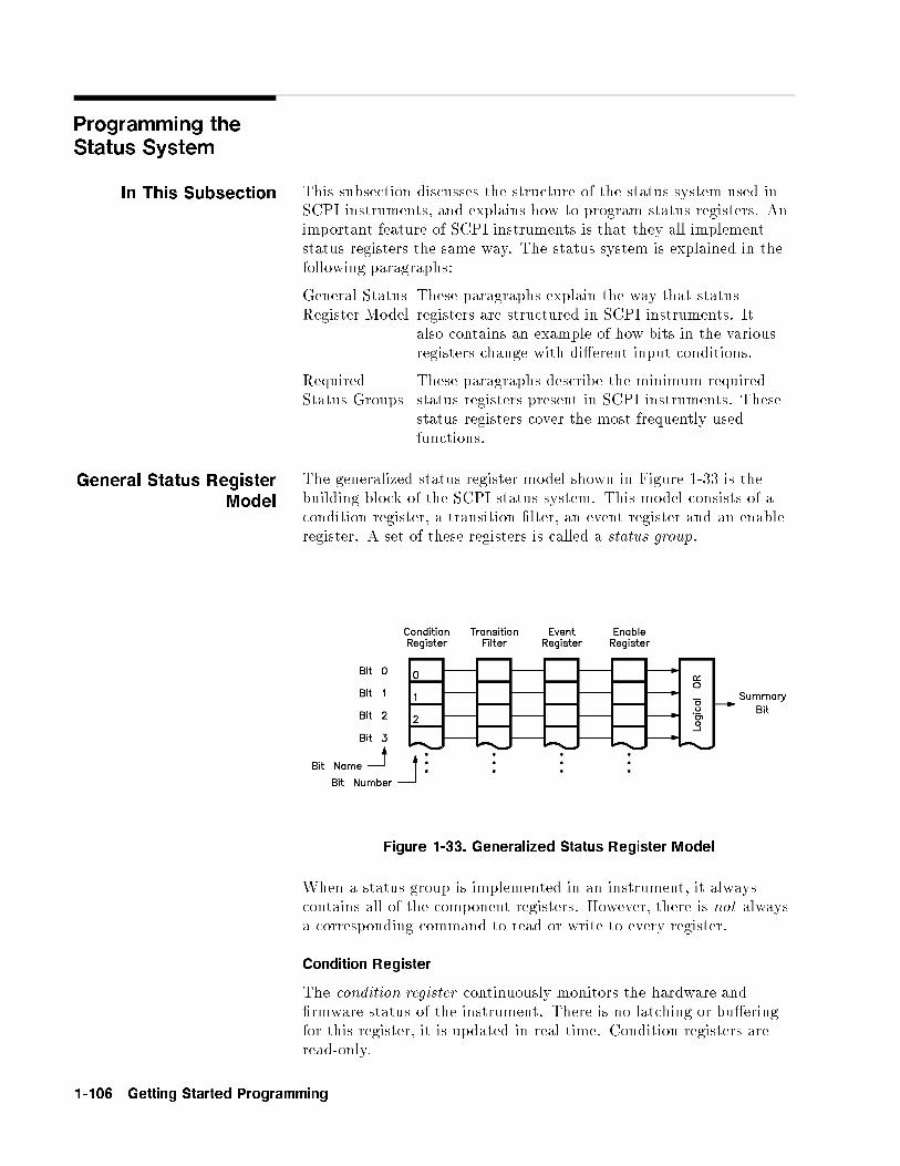
Programming theStatus System
In This Subsection This subsection discusses the structure of the status system used inSCPI instruments, and explains how to program status registers. Animportant feature of SCPI instruments is that they all implementstatus registers the same way. The status system is explained in thefollowing paragraphs:
General StatusRegister Model
These paragraphs explain the way that statusregisters are structured in SCPI instruments. Italso contains an example of how bits in the variousregisters change with di�erent input conditions.
RequiredStatus Groups
These paragraphs describe the minimum requiredstatus registers present in SCPI instruments. Thesestatus registers cover the most frequently usedfunctions.
General Status RegisterModel
The generalized status register model shown in Figure 1-33 is thebuilding block of the SCPI status system. This model consists of acondition register, a transition �lter, an event register and an enableregister. A set of these registers is called a status group.
Figure 1-33. Generalized Status Register Model
When a status group is implemented in an instrument, it alwayscontains all of the component registers. However, there is not alwaysa corresponding command to read or write to every register.
Condition Register
The condition register continuously monitors the hardware and�rmware status of the instrument. There is no latching or bu�eringfor this register, it is updated in real time. Condition registers areread-only.
1-106 Getting Started Programming

There may or may not be a command to read a particular conditionregister.
Transition Filter
The transition �lter speci�es which types of bit state changes in thecondition register will set corresponding bits in the event register.Transition �lter bits may be set for positive transitions (PTR),negative transitions (NTR), or both. Positive means a conditionbit changes from 0 to 1. Negative means a condition bit changesfrom 1 to 0. Transition �lters are read-write. Transition �ltersare una�ected by *CLS (clear status) or queries. They are set toinstrument dependent values at power on and after *RST.
Event Register
The event register latches transition events from the conditionregister, as speci�ed by the transition �lter. Bits in the event registerare latched, and once set they remain set until cleared by a query ora *CLS (clear status). There is no bu�ering, so while an event bit isset, subsequent events corresponding to that bit are ignored. Eventregisters are read-only.
Enable Register
The enable register speci�es the bits in the event register thatcan generate a summary bit. The instrument logically ANDscorresponding bits in the event and enable registers, and ORs allthe resulting bits to obtain a summary bit. Summary bits are inturn recorded in the Status Byte. Enable registers are read-write.Querying an enable register does not a�ect it. There is always acommand to read and write to the enable register of a particularstatus group.
An Example Sequence
Figure 1-34 illustrates the response of a single bit position in atypical status group for various settings. The changing state of thecondition in question is shown at the bottom of the �gure. A smallbinary table shows the state of the chosen bit in each status registerat the selected times T1 to T5.
Getting Started Programming 1-107
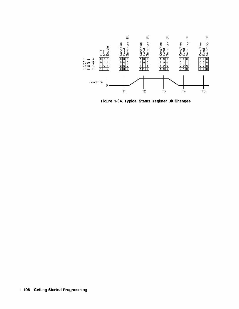
Figure 1-34. Typical Status Register Bit Changes
1-108 Getting Started Programming
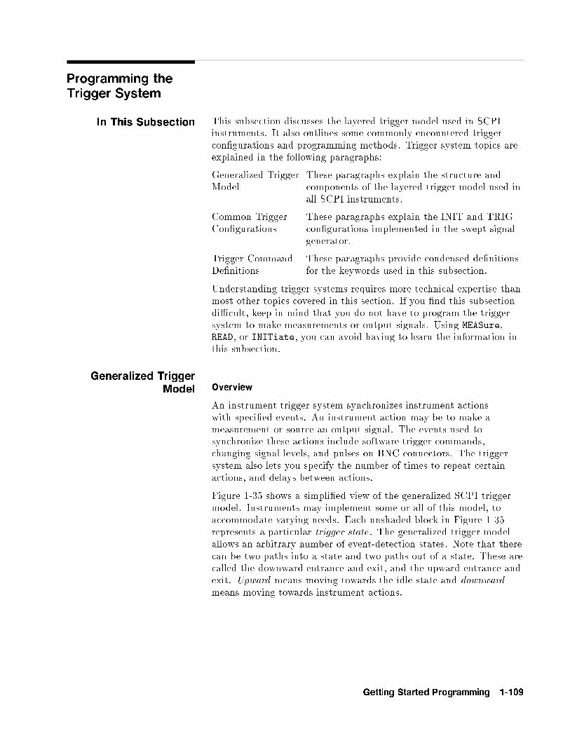
Programming theTrigger System
In This Subsection This subsection discusses the layered trigger model used in SCPIinstruments. It also outlines some commonly encountered triggercon�gurations and programming methods. Trigger system topics areexplained in the following paragraphs:
Generalized TriggerModel
These paragraphs explain the structure andcomponents of the layered trigger model used inall SCPI instruments.
Common TriggerCon�gurations
These paragraphs explain the INIT and TRIGcon�gurations implemented in the swept signalgenerator.
Trigger CommandDe�nitions
These paragraphs provide condensed de�nitionsfor the keywords used in this subsection.
Understanding trigger systems requires more technical expertise thanmost other topics covered in this section. If you �nd this subsectiondi�cult, keep in mind that you do not have to program the triggersystem to make measurements or output signals. Using MEASure,READ, or INITiate, you can avoid having to learn the information inthis subsection.
Generalized TriggerModel Overview
An instrument trigger system synchronizes instrument actionswith speci�ed events. An instrument action may be to make ameasurement or source an output signal. The events used tosynchronize these actions include software trigger commands,changing signal levels, and pulses on BNC connectors. The triggersystem also lets you specify the number of times to repeat certainactions, and delays between actions.
Figure 1-35 shows a simpli�ed view of the generalized SCPI triggermodel. Instruments may implement some or all of this model, toaccommodate varying needs. Each unshaded block in Figure 1-35represents a particular trigger state. The generalized trigger modelallows an arbitrary number of event-detection states. Note that therecan be two paths into a state and two paths out of a state. These arecalled the downward entrance and exit, and the upward entrance andexit. Upward means moving towards the idle state and downwardmeans moving towards instrument actions.
Getting Started Programming 1-109

An instrument moves between adjacent states, depending on itsinternal conditions and the commands that you send. When you �rstturn on power to an instrument, it is in the idle state. You can forcethe instrument to the idle state using :ABORt or *RST. The initiateand event detection trigger states are essentially a list of conditionsthat must be satis�ed to reach the adjacent states. The sequenceoperation state signals the instrument hardware to take some action,and listens for a signal that the action has been taken.
Figure 1-35. Generalized Trigger Model
Details of Trigger States
These paragraphs use ow charts to explain the decision making rulesinside each trigger state. These rules govern how the instrumentmoves between adjacent states. Some of the ow charts referencecommands that have not been discussed yet. These commandsare explained later in this subsection. Keep in mind that thisexplanation covers the most general case. Your particular instrumentmay not implement all of the commands discussed here.
1-110 Getting Started Programming
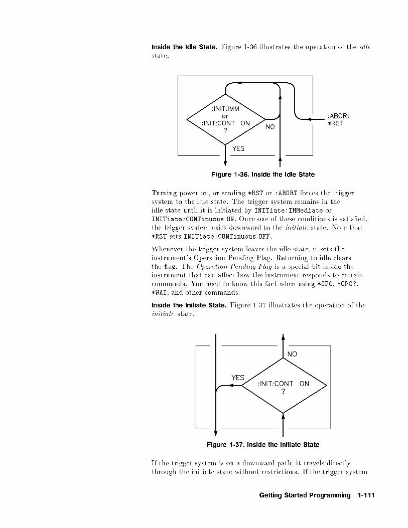
Inside the Idle State. Figure 1-36 illustrates the operation of the idlestate.
Figure 1-36. Inside the Idle State
Turning power on, or sending *RST or :ABORT forces the triggersystem to the idle state. The trigger system remains in theidle state until it is initiated by INITiate:IMMediate orINITiate:CONTinuous ON. Once one of these conditions is satis�ed,the trigger system exits downward to the initiate state. Note that*RST sets INITiate:CONTinuous OFF.
Whenever the trigger system leaves the idle state, it sets theinstrument's Operation Pending Flag. Returning to idle clearsthe ag. The Operation Pending Flag is a special bit inside theinstrument that can a�ect how the instrument responds to certaincommands. You need to know this fact when using *OPC, *OPC?,*WAI, and other commands.
Inside the Initiate State. Figure 1-37 illustrates the operation of theinitiate state.
Figure 1-37. Inside the Initiate State
If the trigger system is on a downward path, it travels directlythrough the initiate state without restrictions. If the trigger system
Getting Started Programming 1-111

is on an upward path, and INITiate:CONTinuous is ON, it exitsdownward to an event-detection state. If the trigger system is on anupward path and INITiate:CONTinuous is OFF, it exits upward tothe idle state.
Inside Event Detection States. Figure 1-38 illustrates the operationof an arbitrary event detection state named <state_name>. Typical<state_names >are TRIGger, ARM, STARt, and STOP.
Normal downward execution is controlled by the source command.
SOURce
The :<state_name>:SOURce command speci�es which particularinput can generate the event required to continue the downwardpath. If the source chosen is a non-analog signal, such as IMMediate,BUS, or TIMer, no further quali�cations are required to generate anevent. If, however, an INTernal or EXTernal analog signal is chosen,additional quali�cations may apply. You specify these additionalquali�cations using appropriate LEVel, SLOPe, and HYSTeresis
commands. Sending *RST sets the SOURce to IMMediate .
The downward path also provides a command to override normaloperation.
IMMediate
The :<state_name>:IMMediate command bypasses event detection,ECOunt, and DELay quali�cations one time. The upward paththrough the event detection state contains only one condition. A:<state_name>:COUNt command sets the number of times thetrigger system must successfully exit that event detection state on adownward path. If this condition is satis�ed, the trigger system exitsupward.
1-112 Getting Started Programming

Figure 1-38. Inside an Event Detection State
Getting Started Programming 1-113
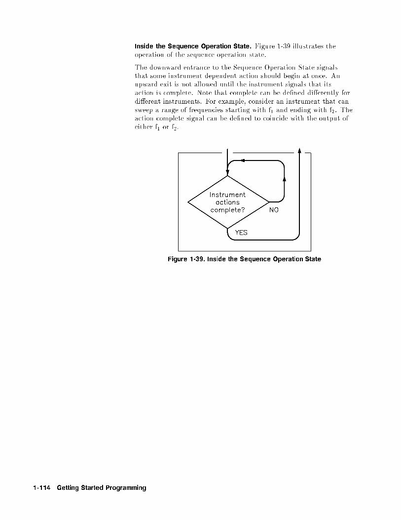
Inside the Sequence Operation State. Figure 1-39 illustrates theoperation of the sequence operation state.
The downward entrance to the Sequence Operation State signalsthat some instrument dependent action should begin at once. Anupward exit is not allowed until the instrument signals that itsaction is complete. Note that complete can be de�ned di�erently fordi�erent instruments. For example, consider an instrument that cansweep a range of frequencies starting with f1 and ending with f2. Theaction-complete signal can be de�ned to coincide with the output ofeither f1 or f2.
Figure 1-39. Inside the Sequence Operation State
1-114 Getting Started Programming
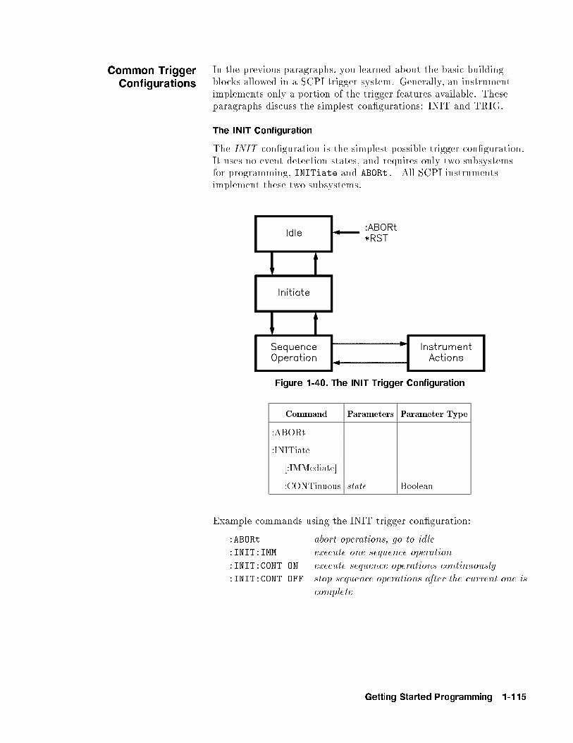
Common TriggerConfigurations
In the previous paragraphs, you learned about the basic buildingblocks allowed in a SCPI trigger system. Generally, an instrumentimplements only a portion of the trigger features available. Theseparagraphs discuss the simplest con�gurations: INIT and TRIG.
The INIT Configuration
The INIT con�guration is the simplest possible trigger con�guration.It uses no event detection states, and requires only two subsystemsfor programming, INITiate and ABORt. All SCPI instrumentsimplement these two subsystems.
Figure 1-40. The INIT Trigger Configuration
Command Parameters Parameter Type
:ABORt
:INITiate
[:IMMediate]
:CONTinuous state Boolean
Example commands using the INIT trigger con�guration:
:ABORt abort operations, go to idle
:INIT:IMM execute one sequence operation
:INIT:CONT ON execute sequence operations continuously
:INIT:CONT OFF stop sequence operations after the current one is
complete
Getting Started Programming 1-115
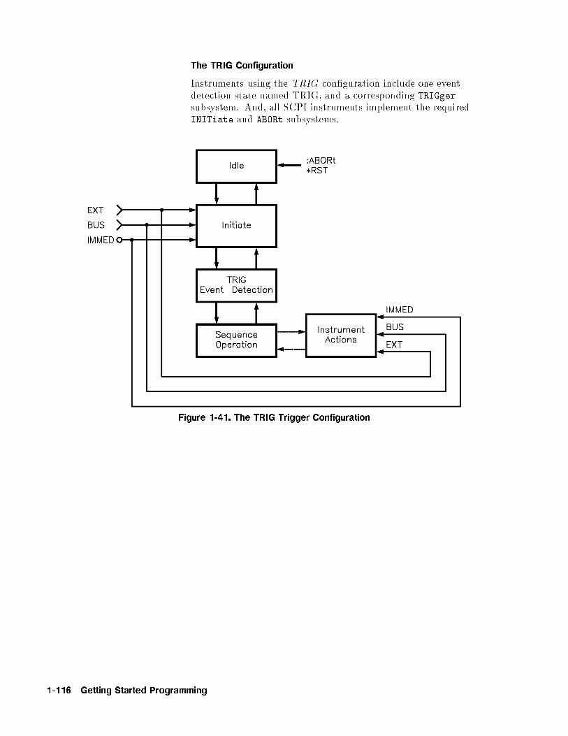
The TRIG Configuration
Instruments using the TRIG con�guration include one eventdetection state named TRIG, and a corresponding TRIGgersubsystem. And, all SCPI instruments implement the requiredINITiate and ABORt subsystems.
Figure 1-41. The TRIG Trigger Configuration
1-116 Getting Started Programming

Description ofTriggering in the
8360 B-Series SweptSignal Generators
The 8360 B-Series swept signal generators follow the SCPI modelof triggering. It is a layered model with the structure shown inFigure 1-42.
Figure 1-42. 8360 Simplified Trigger Model
The process of sweeping involves all 3 of these states. The IDLEstate is where the sweep begins. The IDLE state is left whenthe sweep is initiated. This can happen on a continuous basis(INIT:CONT ON) or on a demand basis (INIT:CONT OFF). Thefunctions of continuous and single sweeps are handled by thiscommand. When the INIT:CONT ON command is given, the sweepis continuously re-initiated. When in the OFF state, the sweep isinitiated with the INIT:IMMediate command.
Once initiated, the wait for trigger state is entered. Here, the triggersignal selected by the TRIG:SOURce command is examined until aTRUE condition is detected. These trigger signals are:
IMMediate This signal is always TRUE.EXTernal This is the external trigger input jack. A positive
transition on this jack constitutes a TRUE signal.BUS This signal is the GPIB <get> (Group Execute
Trigger) message or a *TRG command.
When a TRUE signal is found, the sweep is actually started.
The act of producing the sweep in some cases involves the useof trigger signals. For example, the stepped and list sweepshave modes that allow triggering for point-to-point advancementthrough the sweep. These trigger signals are selected by individualTRIG:SOURce commands in the appropriate subsystems (i.e.LIST:TRIGger:SOURce and SWEep:TRIGger:SOURce). Thede�nition of these signals in the swept signal generator cause the
Getting Started Programming 1-117
sweep to jump to the next point when the signal becomes TRUE,therefore the �rst point in the list or stepped sweeps is producedimmediately upon starting the sweep. Receiving a trigger signal atthe last point causes the IDLE state to be re-entered. Analog sweepsdo not use the trigger signals during the sweep (although the triggersignals are needed to start the sweep as described).
The ABORt command resets any sweep in progress and immediatelyreturns the instrument to the IDLE state.
The *WAI, *OPC and *OPC? commands indicate a complete operationat the end of the sweep upon re-entry into the IDLE state.
Advanced Trigger Configurations
Because the SCPI layered trigger model is expandable, many morecomplex trigger con�gurations are possible.
Trigger KeywordDefinitions
The following paragraphs contain condensed de�nitions of thekeywords used in the command tables. Many of the commands intrigger related subsystems are event commands . Remember thatevent commands cannot be queried. Similarly, event commandshave no related *RST actions or settings. Event commands cause aparticular action to take place inside the swept signal generator.
ABORt
The ABORt command forces the trigger system to the idle state. Anymeasurement or output sequence in process is aborted as quickly aspossible. ABORt does not alter the settings programmed by othercommands, unlike *RST. ABORt is a root level event command andcannot be queried.
IMMediate
The IMMediate command provides a one-time override of the normaldownward path in an event-detection state. The instrument must bein the speci�ed event detection state when IMMediate is received, oran error is generated and the command has no e�ect. For example,the instrument must be in the TRIG state for :TRIGger:IMMediateto work properly. If the instrument is in the idle state, the commandhas no e�ect, and an error would be generated. IMMediate is anevent command and cannot be queried.
ODELay
The ODELay command speci�es the time between the sourcesettling and the time the trigger out signal is sent. Specifying:TRIGger:ODELay <num>{time suffix} instructs the sweptsignal generator to set the speci�ed time as the delay necessary toensure proper settling. Sending *RST sets ODELay to an instrumentdependent value, usually zero.
1-118 Getting Started Programming

SOURce
The SOURce command selects the trigger source for anevent-detection state. Only one source can be speci�ed at a time,and all others are ignored. Sending *RST sets SOURce to IMMediate.
The most commonly used sources are:
BUS
The event detector is satis�ed by either Group ExecuteTrigger(<GET>) or a *TRG command. <GET> is a low levelGPIB message that can be sent using the TRIGGER command inHP BASIC.
EXTernal
An external signal connector is selected as the source.
IMMediate
Quali�ed events are generated automatically. There is no waitingfor a quali�ed event.
Getting Started Programming 1-119
Related Documents
The InternationalInstitute of Electrical
and ElectronicsEngineers.
IEEE Standard 488.1-1987, IEEE Standard Digital Interface forProgrammable Instrumentation. New York, NY, 1987.
This standard de�nes the technical details required to design andbuild an GPIB interface (IEEE 488.1). This standard containselectrical speci�cations and information on protocol that is beyondthe needs of most programmers. However, it can be useful to clarifyformal de�nitions of certain terms used in related documents.
IEEE Standard 488.2-1987, IEEE Standard Codes, Formats,Protocols, and Common Commands For Use with ANSI/IEEE Std488.1-1987. New York, NY, 1987.
This document describes the underlying message formats and datatypes used in SCPI. It is intended more for instrument �rmwareengineers than for instrument user/programmers. However, you may�nd it useful if you need to know the precise de�nition of certainmessage formats, data types, or common commands.
To obtain a copy of either of these documents, write to:
The Institute of Electrical and Electronics Engineers, Inc.345 East 47th StreetNew York, NY 10017USA
Agilent Technologies BASIC 5.0/5.1 Interfacing Techniques. Vol. 2, Speci�c Interfaces,1987.
This HP BASIC manual contains a good non-technical descriptionof the GPIB (IEEE 488.1) interface in chapter 12, \The GPIBInterface". Subsequent revisions of HP BASIC may use a slightlydi�erent title for this manual or chapter. This manual is the bestreference on instrument I/O for HP BASIC programmers.
Agilent Technologies. Tutorial Description of the General PurposeInterface Bus, 1987.
This book provides a thorough overview of GPIB basics for the GPIBsystem designer, programmer, or user.
To obtain a copy of either of these documents, contact theAgilent Technologies representative listed in your telephone directory.
1-120 Getting Started Programming

2
Operating and Programming Reference
How To Use ThisChapter
The operating and programming functions of the synthesizer arelisted in alphabetical order. Each entry has a complete description,complete programming codes, and a cross reference to the mainfunction group and respective menu map. Cross references tooperating and programming examples located in Chapter 1, \GettingStarted", are also given.
Error messages, instrument speci�cations, and menu maps arelocated in their own tabbed sections. Menu maps can be folded outand viewed at the same time as the alphabetical entry. See theillustration below.
For operator's service information, see the Chapter 4, \Operator'sCheck and Routine Maintenance". The operator accessible �SERVICE�softkeys are described in that chapter. Complete �SERVICE� menuand softkey information is provided in the Agilent Technologies8360 B-Series Swept Signal Generator/8360 L-Series Swept CWGenerator Service Guide.
Programming LanguageComparison Table 3-9 cross-references the actions that the instrument can
perform with the programming commands that will prompt thoseactions.
Operating and Programming Reference 2-1

A
Address
Function Group SYSTEM
Menu Map 8
Description TheNNNNNNNNNNNNNNNNNNNNNNNNNNNNN8360 Adrs softkey lets you change the GPIB address of the
swept signal generator. Enter the address desired using the numericentry keys or the up/down arrow keys. The address value may beset between 0 and 30. The swept signal generator stores the addressvalue in non-volatile memory. The default address of the swept signalgenerator is 19.
Programming Codes SCPI: SYSTem:COMMunicate:GPIB:ADDRessAnalyzer: NONE
See Also Connectors,NNNNNNNNNNNNNNNNNNNNNNNNNNNNNGPIB Menu
\Instrument Addresses" in Chapter 1\Programming Typical Measurements" in Chapter 1
aaaaaaaaaaaaaaaaaaaaaaaaaaaaaaaaaaaaaaAdrs Menu
Function Group SYSTEM
Menu Map 8
Description This softkey accesses the GPIB address menu.NNNNNNNNNNNNNNNNNNNNNNNNNNNNNNNNMeter Adrs Controls the system power meter address.
NNNNNNNNNNNNNNNNNNNNNNNNNNNNN8360 Adrs Can control the swept signal generator's address,
depending on the setting of the rear panel GPIBswitch.NNNNNNNNNNNNNNNNNNNNNNNNNNNNNNNNNNNNNN
Printer Adrs Controls the system printer address.
Operating and Programming Reference A-1

NNNNNNNNNNNNNNNNNNNNNNNNNNAdrs Menu
Programming Codes SCPI: NONE, see the individual softkeys listed.Analyzer: NONE
See AlsoNNNNNNNNNNNNNNNNNNNNNNNNNNNNNGPIB Menu , softkeys listed above.\Optimizing Swept Signal Generator Performance" in Chapter 1\GPIB Address Selection" in Chapter 3
A-2 Operating and Programming Reference
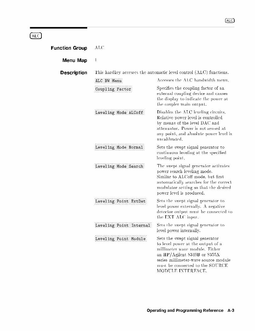
�ALC�
�ALC�
Function Group ALC
Menu Map 1
Description This hardkey accesses the automatic level control (ALC) functions.NNNNNNNNNNNNNNNNNNNNNNNNNNNNNNNNNNNALC BW Menu Accesses the ALC bandwidth menu.NNNNNNNNNNNNNNNNNNNNNNNNNNNNNNNNNNNNNNNNNNNNNNNCoupling Factor Speci�es the coupling factor of an
external coupling device and causesthe display to indicate the power atthe coupler main output.NNNNNNNNNNNNNNNNNNNNNNNNNNNNNNNNNNNNNNNNNNNNNNNNNNNNNNNNNNNNNN
Leveling Mode ALCoff Disables the ALC leveling circuits.Relative power level is controlledby means of the level DAC andattenuator. Power is not sensed atany point, and absolute power level isuncalibrated.NNNNNNNNNNNNNNNNNNNNNNNNNNNNNNNNNNNNNNNNNNNNNNNNNNNNNNNNNNNNNN
Leveling Mode Normal Sets the swept signal generator tocontinuous leveling at the speci�edleveling point.NNNNNNNNNNNNNNNNNNNNNNNNNNNNNNNNNNNNNNNNNNNNNNNNNNNNNNNNNNNNNN
Leveling Mode Search The swept signal generator activatespower search leveling mode.Similar to ALCo� mode, but �rstautomatically searches for the correctmodulator setting so that the desiredpower level is produced.NNNNNNNNNNNNNNNNNNNNNNNNNNNNNNNNNNNNNNNNNNNNNNNNNNNNNNNNNNNNNNNNN
Leveling Point ExtDet Sets the swept signal generator tolevel power externally. A negativedetector output must be connected tothe EXT ALC input.NNNNNNNNNNNNNNNNNNNNNNNNNNNNNNNNNNNNNNNNNNNNNNNNNNNNNNNNNNNNNNNNNNNNNNN
Leveling Point Internal Sets the swept signal generator tolevel power internally.NNNNNNNNNNNNNNNNNNNNNNNNNNNNNNNNNNNNNNNNNNNNNNNNNNNNNNNNNNNNNNNNN
Leveling Point Module Sets the swept signal generatorto level power at the output of amillimeter-wave module. Eitheran HP/Agilent 8349B or 8355Xseries millimeter-wave source modulemust be connected to the SOURCEMODULE INTERFACE.
Operating and Programming Reference A-3

�ALC�
NNNNNNNNNNNNNNNNNNNNNNNNNNNNNNNNNNNNNNNNNNNNNNNNNNNNNNNNNNNNNNNNNLeveling Point PwrMtr Sets the swept signal generator to
level power at an external powermeter. A power meter's recorderoutput must be connected to the EXTALC input.NNNNNNNNNNNNNNNNNNNNNNNNNNNNNNNNNNNNNNNNN
Pwr Mtr Range Speci�es the operating range of anexternal power meter used in anexternal leveling setup. This causesthe swept signal generator display toagree with the power meter's powerindication.
The following paragraphs explain the power control (leveling)function of the swept signal generator in detail.
ALC SYSTEM - OVERVIEW
The ALC system, referred to as a system because it encompassesmore than one functional area, is shown as a simpli�ed blockdiagram in Figure A-1. The purpose of this system is to control theamplitude or power level of the RF energy generated by the sweptsignal generator. It is a feedback control system, in which the outputpower is measured and compared to the desired power level. If theoutput power does not equal the desired power level, the ALC systemchanges the output until they are equal.
Desired power level can be set by either front panel or remoteoperation. As shown in Figure A-1, the inputs and calibration dataare processed by the swept signal generator CPU, which uses thisinformation to set the Level DAC .
In turn, the Level DAC sends a controlling voltage to the LevelControl Circuits . In the presence of modulation, voltages appearingat the AM and/or PULSE inputs contribute to the control of theLevel Control Circuits .
In swept signal generators with optional step attenuators, the powerlevel at the output connector can be reduced by a maximum of90 dB, in 10 dB steps. This is in addition to the control capabilitiesprovided by the Level Control Circuits .
A Feedback Signal to the Level Control Circuits can be provided byeither internal or external detectors. This signal is the comparisonvoltage necessary for accurate, stable, power level settings and goodsource match at various Leveling Points . Alternatively, the powerlevel can be set without using feedback. In this mode however, powerlevel is uncalibrated and is subject to drift with temperature.
The following paragraphs describe the operation of the di�erentleveling modes and leveling points.
A-4 Operating and Programming Reference
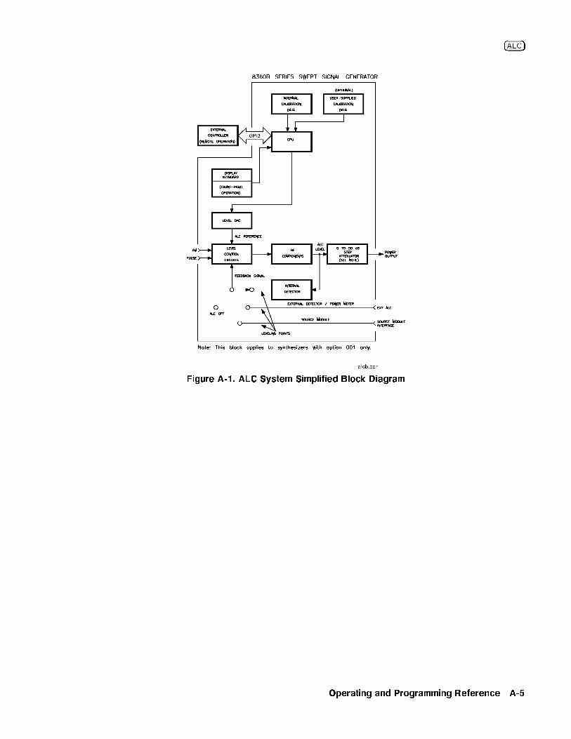
�ALC�
Figure A-1. ALC System Simplified Block Diagram
Operating and Programming Reference A-5
�ALC�
Note Two terms are used in the following discussions: power output andALC level. Power output means actual output power including thee�ects of the attenuator. ALC level means power levels before theattenuator. In swept signal generators without attenuators, these twoterms are equivalent.
Internal Leveling -NNNNNNNNNNNNNNNNNNNNNNNNNNNNNNNNNNNNNNNNNNNNNNNNNNNNNNNNNNNNNNLeveling Mode Normal ,NNNNNNNNNNNNNNNNNNNNNNNNNNNNNNNNNNNNNNNNNNNNNNNNNNNNNNNNNNNNNNNNN
Leveling Point Intrnl
In this con�guration (Figure A-1), power is sensed by a detectorinternal to the swept signal generator and a dc output from thisdetector is fed back to the Level Control Circuits .
The ALC level is limited at the low end by the Level Control Circuitsand at the high end by maximum available power. Noise and driftlimit the range at the low end to �20 dBm or greater.
The combination of RF frequency and RF components (di�erentmodels of swept signal generator have di�erent RF components)limit the ALC range available at the high end. The internalinstructions (�rmware) of the swept signal generator limit the ALClevel range available for request from �20 to +25 dBm. If thepower level requested is higher than the swept signal generator iscapable of producing, the maximum available power is produced,and the message line displays UNLVLED (unleveled). When the sweptsignal generator performs frequency sweeps at certain ALC levels,maximum available power can be exceeded during small portions ofthe sweep; in this case, a ashing UNLVLED message appears.
ALC leveling accuracy depends on power level. Although the ALClevel is useable from �20 to +25 dBm, it is most accurate from�10 to +10 dBm. This fact is re ected in the performancespeci�cations of the swept signal generator.
Coupled Operation. Since many applications require power outputless than �20 dBm, an optional step attenuator has a range of0 to 90 dB, in 10 dB steps. With this option, power output downto �110 dBm is achieved when the Step Attenuator and LevelControl Circuits work in conjunction (see Figure A-1). With theattenuator, the ALC level is normally used over the smaller, moreaccurate portion of its range. Since ALC level accuracy su�ers below�10 dBm, and at some frequencies only +1 dBm of RF output isavailable, the ALC level is set between �10 and 0 dBm. For powerless than �100 dBm, the attenuator is set to 90 dB, and the ALClevel is used from �10 to �20 dBm. At frequencies where poweroutput above 0 dBm is desired, the attenuator is set to 0 dB, and theALC level is used from 0 to +25 dBm (or whatever power is availableat the RF frequency in use).
Coupled operation is assumed by the swept signal generator unlessNNNNNNNNNNNNNNNNNNNNNNNNNNNNNNNNNNNNNNNNNUncoupl Atten or
NNNNNNNNNNNNNNNNNNNNNNNNNNNNNNNNNNNNNNNNNNNNNNNNNNNNNNNNNNNNNNLeveling Mode ALCoff is selected. The proper
combination of ALC level and attenuator setting is decided by the
A-6 Operating and Programming Reference
�ALC�
�rmware. In coupled operation, when desired power output is set via�POWER LEVEL�, the ALC level and attenuator are set automatically toprovide the most accuracy for the power requested.
Uncoupled Operation. In some applications it is advantageous tocontrol the ALC level and attenuator separately, using combinationsof settings that are not available in coupled operation. In uncoupledmode (
NNNNNNNNNNNNNNNNNNNNNNNNNNNNNNNNNNNNNNNNNUncoupl Atten ), when the desired power output is set via
�POWER LEVEL�, only the ALC level is changed. The attenuator setting
is changed viaNNNNNNNNNNNNNNNNNNNNNNNNNNNNNSet Atten .
One use of uncoupled operation is power sweep, where theoutput power linearly tracks the sweep voltage ramp. The sweptsignal generator can generate power sweeps of up to 40 dB,depending on frequency. The power at the start of the sweep isset via �POWER LEVEL� (coupled operation) or by a combination of
�POWER LEVEL� andNNNNNNNNNNNNNNNNNNNNNNNNNNNNNSet Atten (uncoupled operation). The sweep
range is entered by selectingNNNNNNNNNNNNNNNNNNNNNNNNNNNNNNNNNNNPower Sweep . If the sweep range
entered exceeds the ALC range (stop power greater than maximumavailable power), the UNLVLED warning message appears at the end ofsweep. No warning is given at the time of entry. If the start power isentered when the swept signal generator is in coupled operation, theALC level is set no lower than �10 dBm, limiting the available powersweep range. Using uncoupled operation and setting the ALC level to�20 dBm gives an additional 10 dB of sweep range.
External Leveling -NNNNNNNNNNNNNNNNNNNNNNNNNNNNNNNNNNNNNNNNNNNNNNNNNNNNNNNNNNNNNNLeveling Mode Normal ,NNNNNNNNNNNNNNNNNNNNNNNNNNNNNNNNNNNNNNNNNNNNNNNNNNNNNNNNNNNNNNNNN
Leveling Point ExtDet orNNNNNNNNNNNNNNNNNNNNPwrMtr or
NNNNNNNNNNNNNNNNNNNNModule
In externally leveled operations, the output power from the sweptsignal generator is detected by an external sensor. The output of thisdetector is returned to the leveling circuits, and the output power isautomatically adjusted to keep the power constant at the point ofdetection. Figure A-2 shows a basic external leveling arrangement.The output of the detected arm of the splitter or coupler is heldconstant. If the splitter response is at, the output of the otherarm is also constant. This arrangement o�ers superior atness overinternal leveling, especially if long cables are involved. Flatnessmay be improved with user atness correction (�FLTNESS ON/OFF�,NNNNNNNNNNNNNNNNNNNNNNNNNNNNNNNNNNNNNNFltness Menu ) applied at the external leveling point.
Operating and Programming Reference A-7
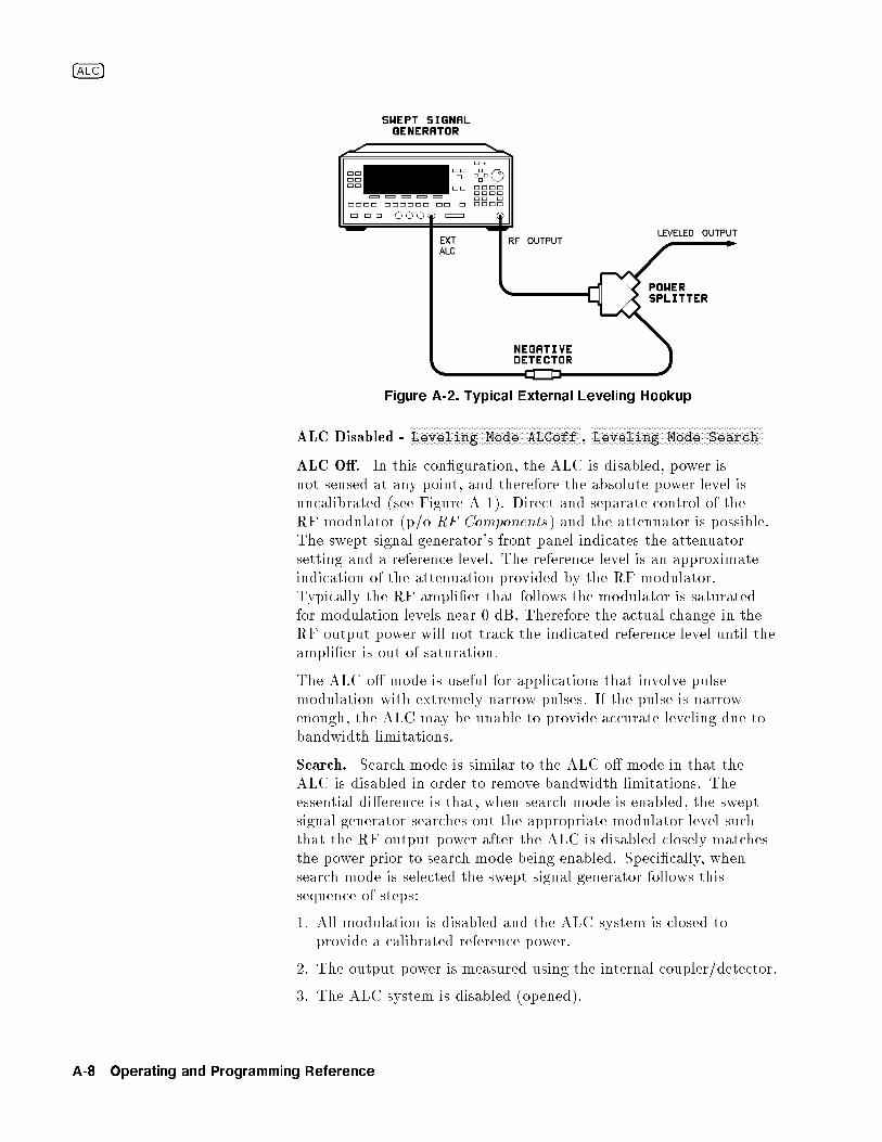
�ALC�
Figure A-2. Typical External Leveling Hookup
ALC Disabled -NNNNNNNNNNNNNNNNNNNNNNNNNNNNNNNNNNNNNNNNNNNNNNNNNNNNNNNNNNNNNNLeveling Mode ALCoff ,
NNNNNNNNNNNNNNNNNNNNNNNNNNNNNNNNNNNNNNNNNNNNNNNNNNNNNNNNNNNNNNLeveling Mode Search
ALC O�. In this con�guration, the ALC is disabled, power isnot sensed at any point, and therefore the absolute power level isuncalibrated (see Figure A-1). Direct and separate control of theRF modulator (p/o RF Components) and the attenuator is possible.The swept signal generator's front panel indicates the attenuatorsetting and a reference level. The reference level is an approximateindication of the attenuation provided by the RF modulator.Typically the RF ampli�er that follows the modulator is saturatedfor modulation levels near 0 dB. Therefore the actual change in theRF output power will not track the indicated reference level until theampli�er is out of saturation.
The ALC o� mode is useful for applications that involve pulsemodulation with extremely narrow pulses. If the pulse is narrowenough, the ALC may be unable to provide accurate leveling due tobandwidth limitations.
Search. Search mode is similar to the ALC o� mode in that theALC is disabled in order to remove bandwidth limitations. Theessential di�erence is that, when search mode is enabled, the sweptsignal generator searches out the appropriate modulator level suchthat the RF output power after the ALC is disabled closely matchesthe power prior to search mode being enabled. Speci�cally, whensearch mode is selected the swept signal generator follows thissequence of steps:
1. All modulation is disabled and the ALC system is closed toprovide a calibrated reference power.
2. The output power is measured using the internal coupler/detector.
3. The ALC system is disabled (opened).
A-8 Operating and Programming Reference

�ALC�
4. While monitoring the internal detector, the RF modulator levelis varied until the detected power is equivalent to the referencepower measured in step 2.
5. Modulation is re-enabled if appropriate.
These steps are performed in approximately 200 �s and are repeatedany time power or frequency is changed.
See Also Softkeys listed above,NNNNNNNNNNNNNNNNNNNNNNNNNNNNNNNNNNNNNNFltness Menu , �MOD�, �POWER LEVEL�,NNNNNNNNNNNNNNNNNNNNNNNNNNNNN
Set Atten
\Externally Leveling the Swept Signal Generator" in Chapter 1\Working with Mixers/Reverse Power E�ects" in Chapter 1\Working with Spectrum Analyzers/Reverse Power E�ects" inChapter 1
Operating and Programming Reference A-9
xFxFxFxFxFxFxFxFxFxFxFxFxFxFxFxFxFxFxFxFxFxFxFxFxFxFxFxFxFxFxFxFxFxFxFxFxFxFxFxFxFxFxFxFxFxFxFxFxFxFxFxFxFxF
ALC Bandwidth
Select Auto
Function Group ALC
Menu Map 1
Description This softkey sets the swept signal generator to choose the ALCbandwidth automatically depending on the current sweep andmodulation conditions. An asterisk next to the key label indicatesthat this feature is active.
Programming Codes SCPI: POWer:ALC:BANDwidth:AUTO ONj1Analyzer: NONE
See AlsoNNNNNNNNNNNNNNNNNNNNNNNNNNNNNNNNNNNALC BW Menu
\Optimizing Swept Signal Generator Performance" in Chapter 1
xFxFxFxFxFxFxFxFxFxFxFxFxFxFxFxFxFxFxFxFxFxFxFxFxFxFxFxFxFxFxFxFxFxFxFxFxFxFxFxFxFxFxFxFxFxFxFxFxFxFxFxFxFxF
ALC Bandwidth
Select High
Function Group ALC
Menu Map 1
Description This softkey sets the swept signal generator to the ALC highbandwidth position (100 kHz). In this mode, the ALC bandwidthoperates in a wide bandwidth for all sweep and modulationconditions. An asterisk next to the key label indicates that thisfeature is active.
Programming Codes SCPI: Sending the swept signal generator an ALC bandwidthfrequency value of >10 kHz causes it to select the high ALCbandwidth mode.
POWer:ALC:BANDwidth:AUTO OFFj0POWer:ALC:BANDwidth <freq>[freq su�x] orMAXimumjMINimum
Analyzer: NONE
See Also �ALC�,NNNNNNNNNNNNNNNNNNNNNNNNNNNNNNNNNNNALC BW Menu
\Optimizing Swept Signal Generator Performance" in Chapter 1
A-10 Operating and Programming Reference

NNNNNNNNNNNNNNNNNNNNNNNNNNNNNNNNALC BW Menu
xFxFxFxFxFxFxFxFxFxFxFxFxFxFxFxFxFxFxFxFxFxFxFxFxFxFxFxFxFxFxFxFxFxFxFxFxFxFxFxFxFxFxFxFxFxFxFxFxFxFxFxFxFxF
ALC Bandwidth
Select Low
Function Group ALC
Menu Map 1
Description This softkey sets the swept signal generator to the ALC lowbandwidth position (10 kHz).
In this mode, the ALC bandwidth operates in a narrow bandwidthfor all sweep and modulation conditions. An asterisk next to the keylabel indicates that this feature is active.
Programming Codes SCPI: Sending the swept signal generator an ALC bandwidthfrequency value of �10 kHz causes it to select the low ALCbandwidth mode.
POWer:ALC:BANDwidth:AUTO OFFj0POWer:ALC:BANDwidth <freq>[freq su�x] orMAXimumjMINimum
Analyzer: NONE
See Also �ALC�,NNNNNNNNNNNNNNNNNNNNNNNNNNNNNNNNNNNALC BW Menu
\Optimizing Swept Signal Generator Performance" in Chapter 1
aaaaaaaaaaaaaaaaaaaaaaaaaaaaaaaaaaaaaaaaaaaaaaALC BW Menu
Function Group ALC
Menu Map 1
Description This softkey reveals the softkeys of the ALC bandwidth select menu.NNNNNNNNNNNNNNNNNNNNNNNNNNNNNNNNNNNNNNNNNNNNNNNNNNNNNNNNNNNNNNNNNNNNNNNNNNNNNALC Bandwidth Select Auto Sets the ALC bandwidth to be
automatically chosen by the sweptsignal generator, depending on thecurrent sweep and modulationconditions.NNNNNNNNNNNNNNNNNNNNNNNNNNNNNNNNNNNNNNNNNNNNNNNNNNNNNNNNNNNNNNNNNNNNNNNNNNNNN
ALC Bandwidth Select High Sets the ALC bandwidth to thehigh bandwidth position (100 kHz),and to remain there for all sweepand modulation conditions.
Operating and Programming Reference A-11
NNNNNNNNNNNNNNNNNNNNNNNNNNNNNNNNALC BW Menu
NNNNNNNNNNNNNNNNNNNNNNNNNNNNNNNNNNNNNNNNNNNNNNNNNNNNNNNNNNNNNNNNNNNNNNNNNNALC Bandwidth Select Low Sets the ALC bandwidth to the low
bandwidth position (10 kHz), andto remain there for all sweep andmodulation conditions.
See Also �ALC�\Optimizing Swept Signal Generator Performance" in Chapter 1
aaaaaaaaaaaaaaaaaaaaaaaaaaaaaaaaaaaaaaaaaaaaaaaaaaaaaaAltrnate Regs
Function Group SYSTEM
Menu Map 8
Description This softkey causes the swept signal generator to alternate onsuccessive sweeps between the present instrument state and a secondinstrument state stored in an internal register (1 to 8). SelectNNNNNNNNNNNNNNNNNNNNNNNNNNNNNNNNNNNNNNNNNAltrnate Regs once to turn it on, a second time to turn it o�. Anasterisk next to the key label indicates that this feature is active.
Programming Codes SCPI:
SYSTem:ALTernate:STATe ONjOFFj1j0SYSTem:ALTernate <num>jMAXimumjMINimum
Analyzer: AL1n, where n= 1 through 8 function on, AL0 function o�
See Also �RECALL�, �SAVE�\Saving and Recalling an Instrument State" in Chapter 1
A-12 Operating and Programming Reference

NNNNNNNNNNNNNNNNNNNNNNNNNNNNNNNNNNNNNNNNAM BW Cal Once
aaaaaaaaaaaaaaaaaaaaaaaaaaaaaaaaaaaaaaaaaaaaaaaaaaaaaaaaaaaaaaaaaAM BW Cal Always
Function Group USER CAL
Menu Map 9
Description This softkey causes an AM bandwidth calibration to be performedevery time a frequency or power parameter is changed.
Programming Codes SCPI: CALibration:AM:AUTO ONAnalyzer: NONE
See Also Modulation
aaaaaaaaaaaaaaaaaaaaaaaaaaaaaaaaaaaaaaaaaaaaaaaaaaaaaaaaaAM BW Cal Once
Function Group USER CAL
Menu Map 9
Description This softkey causes a single AM bandwidth calibration to beperformed.
Programming Codes SCPI: CALibration:AM:[EXECute]Analyzer: NONE
See Also Modulation
Operating and Programming Reference A-13
aaaaaaaaaaaaaaaaaaaaaaaaaaaaaaaaaaaaaaaaaaaaaaAM Cal Menu
Function Group USER CAL
Menu Map 9
Description This softkey accesses the AM bandwidth calibration menu.NNNNNNNNNNNNNNNNNNNNNNNNNNNNNNNNNNNNNNNNNNNNNNNNNNAM BW Cal Always Causes an AM bandwidth calibration
to be performed every time afrequency or power parameter ischanged.NNNNNNNNNNNNNNNNNNNNNNNNNNNNNNNNNNNNNNNNNNNN
AM BW Cal Once Causes a single AM bandwidthcalibration to be performed.
See Also Softkeys listed above.
aaaaaaaaaaaaaaaaaaaaaaaaaaaaaaAM Menu
Function Group �MOD�
Menu Map 4
Description This softkey (Option 002 only) accesses the amplitude modulationsoftkeys. These softkeys engage external and internal amplitudemodulation. They allow you to de�ne the scaling, waveform, rate,and depth of the internal AM.NNNNNNNNNNNNNNNNNNNNNNNNNNNNNNNNNNNNNNNNNAM On/Off Ext Toggles on and o� the amplitude modulation mode
for an external AM source.NNNNNNNNNNNNNNNNNNNNNNNNNNNNNNNNNNNNNNNNNAM On/Off Int Toggles on and o� the amplitude modulation mode
using the internal AM generator.NNNNNNNNNNNNNNNNNNNNNNNNNNNNNNNNNNNNNNNNNNNNNNNNNNInternal AM Rate
Sets the rate of the internal amplitude modulation.NNNNNNNNNNNNNNNNNNNNNNNNNNNNNNNNNNNNNNNNNNNNNNNNNNNNNInternal AM Depth
Sets the depth of the internal amplitudemodulation.NNNNNNNNNNNNNNNNNNNNNNNNNNNNNNNNNNNNNNNNNNNN
AM Type 100%/V Sets the scale to linear at 100% per volt.NNNNNNNNNNNNNNNNNNNNNNNNNNNNNNNNNNNNNNNNNNNNAM Type 10dB/V Sets the scale to exponential at 10 dB per volt.
NNNNNNNNNNNNNNNNNNNNNNNDeep AM Opens the ALC loop when the detected signal
level power is below the detector's sensing range.
A-14 Operating and Programming Reference
NNNNNNNNNNNNNNNNNNNNNNNNNNNNNNNNNNNNNNNNNNNNNNNNAM On/Off 10 dB/V
NNNNNNNNNNNNNNNNNNNNNNNNNNNNNNNNNNNNNNNNNWaveform Menu Displays the waveforms for internal amplitude
modulation.
Programming Codes SCPI: NONE, see the individual softkeys listed.Analyzer: NONE
See Also �MOD�, also see \AM" and \Modulation".
aaaaaaaaaaaaaaaaaaaaaaaaaaaaaaaaaaaaaaaaaaaaaaaaaaaaaaaaaaaaaaaaaaaaaAM On/Off 10 dB/V
Function Group MOD (MODULATION)
Menu Map 4
Description This softkey activates the exponentially-scaled amplitude modulationfunction. Amplitude modulation lets the RF output of the sweptsignal generator be continuously and exponentially varied at a ratedetermined by the AM input. See \Speci�cations" for the AMcharacteristics, input range, and damage level. An asterisk next tothe key label indicates that this feature is active.
Programming Codes SCPI:
AM:TYPE EXPponentialAM[:STATE] ONjOFFj1j0
Analyzer: NONE
See Also �ALC�, CONNECTORS, �MOD�\Optimizing Swept Signal Generator Performance" in Chapter 1
Operating and Programming Reference A-15

aaaaaaaaaaaaaaaaaaaaaaaaaaaaaaaaaaaaaaaaaaaaaaaaaaaaaaaaaaaaaaaaaAM On/Off 100%/V
Function Group MOD (MODULATION)
Menu Map 4
Description This softkey activates the linearly scaled amplitude modulationfunction. The amplitude of the RF output changes linearly as afunction of AM input changes. See \Speci�cations" for the AMcharacteristics, input range, and damage level. An asterisk next tothe key label indicates that this feature is active.
Programming Codes SCPI:
AM:TYPE LINearAM[:STATE] ONjOFFj1j0
Analyzer: AM1 function on, AM0 function o�
See Also �ALC�, CONNECTORS, �MOD�\Optimizing Swept Signal Generator Performance" in Chapter 1
aaaaaaaaaaaaaaaaaaaaaaaaaaaaaaaaaaaaaaaaaaaaaaaaaaaaaaAM On/Off Ext
Function Group �MOD�
Menu Map 4
Description This softkey (Option 002 only) activates the amplitude modulationmode for an external source. The AM source is connected to the AMmodulation connector.
When external AM is in e�ect, the RF output is amplitudemodulated with a rate and depth set by the external source.Amplitude scaling is controlled by the following softkeys:NNNNNNNNNNNNNNNNNNNNNNNNNNNNNNNNNNNNNNNNNNNNAM Type 100%/V
NNNNNNNNNNNNNNNNNNNNNNNNNNNNNNNNNNNNNNNNNNNNAM Type 10dB/V . An asterisk next to the key
label indicates that external AM is active and AM is displayed on themessage line.
A-16 Operating and Programming Reference

NNNNNNNNNNNNNNNNNNNNNNNNNNNNNNNNNNNNNAM On/Off Int
Programming Codes SCPI:
AM:SOURce EXTernalAM:STATe ON/OFF
Analyzer: AM1 function on, AM0 function o�
See Also �MOD�, also see \AM" and \Modulation".
aaaaaaaaaaaaaaaaaaaaaaaaaaaaaaaaaaaaaaaaaaaaaaaaaaaaaaAM On/Off Int
Function Group �MOD�
Menu Map 4
Description This softkey (Option 002 only) activates the internal amplitudemodulation mode. No external source is needed.
When internal AM is in e�ect, the parameters are controlled bythe following softkeys:
NNNNNNNNNNNNNNNNNNNNNNNNNNNNNNNNNNNNNNNNNNNNNNNNNNInternal AM Rate
NNNNNNNNNNNNNNNNNNNNNNNNNNNNNNNNNNNNNNNNNNNNNNNNNNNNNInternal AM DepthNNNNNNNNNNNNNNNNNNNNNNNNNNNNNNNNNNNNNNNNNNNN
AM Type 100%/VNNNNNNNNNNNNNNNNNNNNNNNNNNNNNNNNNNNNNNNNNNNNAM Type 10dB/V
NNNNNNNNNNNNNNNNNNNNNNNDeep AM
NNNNNNNNNNNNNNNNNNNNNNNNNNNNNNNNNNNNNNNNNWaveform Menu .
An asterisk next to the key label indicates that internal AM is activeand AM is displayed on the message line. Both amplitude and pulsemodulation can be in e�ect simultaneously.
Programming Codes SCPI:
AM:SOURce INTernalAM:STATe ON/OFF
Analyzer: NONE
See Also �MOD�, also see \AM" and \Modulation".
Operating and Programming Reference A-17

aaaaaaaaaaaaaaaaaaaaaaaaaaaaaaaaaaaaaaaaaaaaaaaaaaAmpl Markers
Function Group MARKER
Menu Map 3
Description Active markers are normally displayed as intensi�ed dots on a CRTdisplay. With
NNNNNNNNNNNNNNNNNNNNNNNNNNNNNNNNNNNNNNAmpl Markers selected, active markers are displayed
as amplitude spikes (an abrupt discontinuity in the sweep trace).The marker amplitude can be varied. The swept signal generatordisplays: --> AMPLITUDE MARKER SIZE: XXXX dB. Where XXXXrepresents an amplitude value. Use the rotary knob, the step keys,or the numerical entry keys with the dB(m) terminator key toset the desired value. If a small change is required, the left andright arrow keys can be used to underline the digit to be changed.Select
NNNNNNNNNNNNNNNNNNNNNNNNNNNNNNNNNNNNNNAmpl Markers again to return to the normal intensi�ed dot
representation. See \Speci�cations" for the range of acceptableamplitude values. An asterisk next to the key label indicates thisfeature is active.
Programming Codes SCPI: MARKer:AOFFAnalyzer: AK1 function on, AK0 function o�.
See Also �MARKER�\Marker Operation" in Chapter 1\Setting Up A Typical Sweep, Example Program 3" in Chapter 1
aaaaaaaaaaaaaaaaaaaaaaaaaaaaaaaaaaaaaaaaaaaaaaaaaaaaaaaaaaaaaAM Type 10 dB/V
Function Group MOD (MODULATION)
Menu Map 4
Description This softkey (Option 002 only) scales the amplitude modulationexponentially. Amplitude modulation lets the RF output of theswept signal generator be continuously and exponentially varied ata rate determined by the AM input or at a rate set by softkey forinternal AM. See \Speci�cations" for the AM characteristics, inputrange, and damage level. An asterisk next to the key label indicatesthat this feature is active.
A-18 Operating and Programming Reference
NNNNNNNNNNNNNNNNNNNNNNNNNNNNNNNNNNNNNNNNAM Type 100%/V
Programming Codes SCPI:
AM:TYPE EXPponential
Analyzer: NONE
See Also �ALC�, CONNECTORS, �MOD�\Optimizing Swept Signal Generator Performance" in Chapter 1
aaaaaaaaaaaaaaaaaaaaaaaaaaaaaaaaaaaaaaaaaaaaaaaaaaaaaaaaaAM Type 100%/V
Function Group MOD (MODULATION)
Menu Map 4
Description This softkey (Option 002 only) scales the amplitude modulationfunction linearly. The amplitude of the RF output changes linearlyas a function of AM input changes (or at a rate set by softkey forinternal AM). See \Speci�cations" for the AM characteristics, inputrange, and damage level. An asterisk next to the key label indicatesthat this feature is active.
Programming Codes SCPI:
AM:TYPE LINear
Analyzer: AM1 function on, AM0 function o�
See Also �ALC�, CONNECTORS, �MOD�\Optimizing Swept Signal Generator Performance" in Chapter 1
Operating and Programming Reference A-19

ANALYZER STATUSREGISTER
Function Group NONE
Menu Map NONE
Description The following is the status register structure of the swept signalgenerator when the analyzer programming language is selected. Thisstatus structure is the structurally and syntactically the same as onthe HP/Agilent 8340/41.
OS(2B) Output Status bytes, is used to read the two 8-bit statusbytes from the swept signal generator. The �rst status byteconcerns the cause of an SRQ (Service Request), while thesecond status byte concerns failures and faults, as follows:
STATUS BYTE (#1)
Bit # 7 6 5 4 3 2 1 0
Decimal
Value
128 64 32 16 8 4 2 1
Function SRQ on newfrequenciesor sweeptime ine�ect.
REQUESTSERVICE(RQS)
SRQ onGPIB orsyntax error.
SRQ onEnd ofSweep
SRQ onRF Settled
SRQ onChanged inExtendedStatusByte
SRQ onNumericEntryCompleted(GPIB orFrontPanel)
SRQ onAny FrontPanel KeyPressed
EXTENDED STATUS BYTE (#2)
Bit # 7 6 5 4 3 2 1 0
DecimalValue
128 64 32 6 8 4 2 1
Function FaultIndicatorOn
RF Unleveled PowerFailure
RF Unlocked ExternalFrequencyReferenceSelected
OvenCold
OverModulation
Self TestFailed
Status Byte 1
Bit 0: SRQ caused by a key closure on the front panel of the sweptsignal generator (use the OM code to determine the front panelstatus).
Bit 1: SRQ caused by the completion of a numeric entry (use the OAcode to determine the value of the numerical entry).
Bit 2: SRQ caused by a change in the extended status byte (statusbyte 2) a�ected by the RE-coded mask (see the RE code for anexplanation of this masking).
A-20 Operating and Programming Reference
ANALYZER STATUS REGISTER
Bit 3: SRQ caused by the completion of phase locking and thesettling of the RF source (use the OK code to determine the last lockfrequency).
Bit 4: SRQ on end-of-sweep or mid-sweep update in NA (networkanalyzer code) mode.
Bit 5: SRQ caused by GPIB syntax error.
Bit 6: SERVICE REQUEST; by IEEE-488 convention, theinstrument needs service from the controller when this bit is set true.
Bit 7: SRQ caused by a change in the coupled parameters (startfrequency, center frequency, and sweep time). Use the OC code todetermine the new values of the coupled parameters.
Status Byte 2 (Extended Status Byte)
Bit 0: Self test failed at power on or at Instrument Preset. This bitremains latched until this status byte has been read, or until clearedby the CS or CLEAR 719 commands.
Bit 1: Excessive amplitude modulation input.
Bit 2: Oven for the reference crystal oscillator is not at operatingtemperature.
Bit 3: External reference frequency is selected.
Bit 4: RF is unlocked (UNLOCK appears in the message line). UseOF to determine the source of the unlocked output. This bit remainslatched until this status byte has been read, or until cleared by theCS or CLEAR 719 commands.
Bit 5: ac line power interruption has occurred since the lastInstrument Preset. This bit also remains latched until read orcleared.
Bit 6: RF is unleveled (use OR to determine present power level).This bit also remains latched until read or cleared.
Bit 7: FAULT message is displayed. Use OF to determine the causeof the fault.
See Also SCPI STATUS REGISTERChapter 3
Operating and Programming Reference A-21
Arrow Keys
Function Group ENTRY
Menu Map NONE
Description This group of entry keys lets you manipulate numerical values in theactive entry line.�(� and �)� arrow keys identify (by underlining) the digit to bechanged. For example, if CW frequency is in the active entry line,and the display indicates:--> CW: 10005.000000 MHz
You may wish to change the 5 to a 6. Press the �)� �ve times untilthe underline is under the 5. Now use the rotary knob or the �*�to change the 5 to a 6. The underlined digit remains the activecharacter in this function until the swept signal generator is preset,turned o�, or the underline is moved completely left or right.
The �*� and �+� arrow keys increment or decrement the numericvalue by a predetermined amount. The increment value depends onthe active function and the step value set. All increment values aredefaulted to their original values when the swept signal generatoris preset (unless
NNNNNNNNNNNNNNNNNNNNNNNNNNNNNNNNNNNNNNNNNNNNNNNNNNPreset Mode User has de�ned the default
di�erently).
Programming Codes SCPI: NONEAnalyzer: NONE
See AlsoNNNNNNNNNNNNNNNNNNNNNNNNNNNNNNNNNNNNNNFltness Menu ,
NNNNNNNNNNNNNNNNNNNNNNNNNNNNNList Menu
\Entry Area" in Chapter 1\Creating and Applying the User Flatness Correction Array" inChapter 1
A-22 Operating and Programming Reference

�ASSIGN�
�ASSIGN�
Function Group USER DEFINED
Menu Map NONE
Description This hardkey lets you select any softkey and assign its function to1 of 12 user de�ned keys in the �USER DEFINED� Menu. The followingmessage appears on the swept signal generator display: --> Press
MENU KEY to be assigned. Complete keypaths are assigned not just
the key label. For example, assigningNNNNNNNNNNNNNNNNNNNNNNNNNNNNNList Menu to the user de�ned
menu, copies the complete structure (keypath) of that key. All of thepages and lower level menus are placed within the user de�ned menu.
Programming Codes SCPI: NONEAnalyzer: NONE
See Also USER DEFINED �MENU�
Operating and Programming Reference A-23

aaaaaaaaaaaaaaaaaaaaaaaaaaaaaaaaaaaaaaaaaaaaaaaaaaaaaaaaaAuto Fill Incr
Function Group FREQUENCY, POWER
Menu Map 2, 5
Description This softkey is used in two locations:NNNNNNNNNNNNNNNNNNNNNNNNNNNNNNNNNNNNNNFltness Menu andNNNNNNNNNNNNNNNNNNNNNNNNNNNNN
List Menu .
Flatness Menu - When selected, the swept signal generator waits fora frequency increment value to be entered. --> Increment: isdisplayed in the active entry area. A list of frequencies is createdautomatically, beginning at the auto �ll start frequency and alwaysending with the auto �ll stop frequency. The swept signal generatoruses the increment value on all points, but if the stop frequencyrequires a di�erent increment to be used to be exact, the sweptsignal generator simply ends the frequency list at the stop frequencydisregarding the increment value.
If the increment value requested creates a list that exceeds thenumber of elements available, the following message appears:
TOO MANY CORRECTION PTS REQUESTED
List Menu - When selected, the swept signal generator waits fora frequency increment value to be entered. --> Increment: isdisplayed in the active entry area. A list of frequencies is createdautomatically, with all points separated by the frequency incrementvalue. The list begins at the auto �ll start frequency and ends at afrequency less than or equal to the auto �ll stop frequency.
If the increment value requested creates a list that exceeds thenumber of points available (801), the following message appears:
TOO MANY LIST PTS REQUESTED
Programming Codes SCPI: NONE, seeNNNNNNNNNNNNNNNNNNNNNNNNNNNNNNNNNNNNNNFltness Menu or
NNNNNNNNNNNNNNNNNNNNNNNNNNNNNList Menu
Analyzer: NONE
See AlsoNNNNNNNNNNNNNNNNNNNNNNNNNNNNNNNNNNNNNNFltness Menu ,
NNNNNNNNNNNNNNNNNNNNNNNNNNNNNList Menu
\Optimizing Swept Signal Generator Performance" in Chapter 1
A-24 Operating and Programming Reference

NNNNNNNNNNNNNNNNNNNNNNNNNNNNNNNNNNNNNNNNAuto Fill #Pts
aaaaaaaaaaaaaaaaaaaaaaaaaaaaaaaaaaaaaaaaaaaaaaaaaaaaaaaaaAuto Fill #Pts
Function Group FREQUENCY, POWER
Menu Map 2, 5
Description This softkey is used in two locations:NNNNNNNNNNNNNNNNNNNNNNNNNNNNNNNNNNNNNNFltness Menu andNNNNNNNNNNNNNNNNNNNNNNNNNNNNN
List Menu .
Flatness Menu - When selected, the swept signal generator waits fora numeric value representing the number of correction points to beentered. --> Number of Correction Points: is displayed in theactive entry area. A list of frequencies containing the number ofspeci�ed points is created automatically. The list begins at the auto�ll start frequency and ends at the auto �ll stop frequency. The restof the points are equally spaced between them. A minimum of twopoints must be entered.
If the number of points requested creates a list that exceeds thenumber of elements available (801), the following message appears:
TOO MANY CORRECTION PTS REQUESTED
List Menu - When selected, the swept signal generator waits for anumeric value representing the number of list points to be entered.--> Number of List Frequencies: is displayed in the activeentry area. A list of frequencies containing the number of speci�edpoints is created automatically. The list begins at the auto �ll startfrequency and ends at the auto �ll stop frequency. The rest of thepoints are equally spaced between them. A minimum of two pointsmust be entered.
If the number of points requested creates a list that exceeds thenumber of points available (801), the following message appears:
Error...too many list points requested.
Points used: 0
Points available: 801
Programming Codes SCPI: NONE, seeNNNNNNNNNNNNNNNNNNNNNNNNNNNNNNNNNNNNNNFltness Menu or
NNNNNNNNNNNNNNNNNNNNNNNNNNNNNList Menu
Analyzer: NONE
See AlsoNNNNNNNNNNNNNNNNNNNNNNNNNNNNNNNNNNNNNNFltness Menu ,
NNNNNNNNNNNNNNNNNNNNNNNNNNNNNList Menu
\Optimizing Swept Signal Generator Performance" in Chapter 1
Operating and Programming Reference A-25

aaaaaaaaaaaaaaaaaaaaaaaaaaaaaaaaaaaaaaaaaaaaaaaaaaaaaaaaaaaaaAuto Fill Start
Function Group FREQUENCY, POWER
Menu Map 2, 5
Description This softkey is used in two locations:NNNNNNNNNNNNNNNNNNNNNNNNNNNNNNNNNNNNNNFltness Menu andNNNNNNNNNNNNNNNNNNNNNNNNNNNNN
List Menu . The operation is the same in both applications.
This softkey enables the entry of a start frequency used to determinethe beginning frequency of the automatic �lling array. The arrayis not created until either the increment value or the number ofpoints is assigned. The auto �ll start frequency does not a�ect theswept signal generator start frequency. When
NNNNNNNNNNNNNNNNNNNNNNNNNNNNNNNNNNNNNNNNNNNNNNNAuto Fill Start is
selected, the active entry area indicates:
--> Fill Start: XXXXXXXXX MHz
where X represents a numeric value. Unless a previous entry wasmade, the display indicates the swept signal generator minimumfrequency.
Programming Codes SCPI: NONE, seeNNNNNNNNNNNNNNNNNNNNNNNNNNNNNNNNNNNNNNFltness Menu or
NNNNNNNNNNNNNNNNNNNNNNNNNNNNNList Menu
Analyzer: NONE
See AlsoNNNNNNNNNNNNNNNNNNNNNNNNNNNNNNNNNNNNNNFltness Menu ,
NNNNNNNNNNNNNNNNNNNNNNNNNNNNNList Menu
\Optimizing Swept Signal Generator Performance" in Chapter 1
A-26 Operating and Programming Reference
NNNNNNNNNNNNNNNNNNNNNNNNNNNNNNNNNNNNNNNNAuto Fill Stop
aaaaaaaaaaaaaaaaaaaaaaaaaaaaaaaaaaaaaaaaaaaaaaaaaaaaaaaaaAuto Fill Stop
Function Group FREQUENCY, POWER
Menu Map 2, 5
Description This softkey is used in two locations:NNNNNNNNNNNNNNNNNNNNNNNNNNNNNNNNNNNNNNFltness Menu andNNNNNNNNNNNNNNNNNNNNNNNNNNNNN
List Menu . The operation is the same in both applications.
This softkey enables the entry of a stop frequency used to determinethe ending frequency of the automatic �lling array. The array is notcreated until either the increment value or the number of points isassigned. The auto �ll stop frequency does not a�ect the swept signalgenerator stop frequency. When
NNNNNNNNNNNNNNNNNNNNNNNNNNNNNNNNNNNNNNNNNNNNAuto Fill Stop is selected, the
active entry area indicates:
--> Fill Stop: XXXXXXXXX MHz
where X represents a numeric value. Unless a previous entry wasmade, the display indicates the swept signal generator maximumfrequency.
Programming Codes SCPI: NONE, seeNNNNNNNNNNNNNNNNNNNNNNNNNNNNNNNNNNNNNNFltness Menu or
NNNNNNNNNNNNNNNNNNNNNNNNNNNNNList Menu
Analyzer: NONE
See AlsoNNNNNNNNNNNNNNNNNNNNNNNNNNNNNNNNNNNNNNFltness Menu ,
NNNNNNNNNNNNNNNNNNNNNNNNNNNNNList Menu
\Optimizing Swept Signal Generator Performance" in Chapter 1
Operating and Programming Reference A-27
aaaaaaaaaaaaaaaaaaaaaaaaaaaaaaaaaaaaaaaaaaAuto Track
Function Group POWER, USER CAL
Menu Map 5, 9
Description This softkey optimizes the tracking of the swept signal generator'soutput �lter to the oscillator. Use it to maximize RF power output.The swept signal generator displays: Peaking At: XXXXX MHz,where XXXXX represents frequency values. Peaking begins atthe low frequency end and steps through to the high end of thefrequency range. Auto Track is complete when the display returnsto its original state. On swept signal generators without a stepattenuator provide a good source match on the RF connector. Usea power sensor or a 10 dB attenuator. If a good source match isnot provided, the swept signal generator can mistrack because ofexcessive re ections at the output.
Programming Codes SCPI: CALibration:TRACkAnalyzer: SHRP
See AlsoNNNNNNNNNNNNNNNNNNNNNNNNNNNNNNNNNNNNNNNNNTracking Menu
\Optimizing Swept Signal Generator Performance" in Chapter 1
A-28 Operating and Programming Reference
B
aaaaaaaaaaaaaaaaaaaaaaaaaaaaaaaaaaaaaaaaaaBlank Disp
Function Group SYSTEM
Menu Map 8
Description When this softkey is selected, it causes the top four lines of thedisplay to blank and remain blank until the �PRESET� key is pressed.Blanking the display prevents sensitive information from beingdisplayed. As an added bene�t, remote execution time is reducedbecause the display does not require refreshing. This key does notdisable any other key functions. An asterisk next to the key labelindicates this function is active.
Programming Codes SCPI: DISPlay[:STATe] ONjOFFj0j1Analyzer: SHS11 disables the display, SHS10 re-enables the display
See AlsoNNNNNNNNNNNNNNNNNNNNNNNNNNNNNNNNNNNNNNNNNSecurity Menu
Operating and Programming Reference B-1

C
�CENTER�
Function Group FREQUENCY
Menu Map NONE
Description This hardkey lets you select the center frequency for centerfrequency/frequency span swept operation. When you press �CENTER�,the swept signal generator displays: --> CENTER: XXXXX MHz, whereXXXXX represents a frequency value. Use the entry area to set thedesired value.
Certain center frequency and frequency span combinations cause theswept signal generator to limit the value entered. In general, anycombination that would cause the swept signal generator to exceedits minimum or maximum speci�ed frequency will be limited.
Programming Codes SCPI:
FREQuency:CENTer <num>[freq su�x] orMAXimumjMINimumjUPjDOWNFREQuency:MODE SWEep
Analyzer: CF
See Also �SPAN�, �START�, �STOP�\Center Frequency/Span Operation" in Chapter 1
Operating and Programming Reference C-1

aaaaaaaaaaaaaaaaaaaaaaaaaaaaaaaaaaaaaaaaaaaaaaaaaaaaaaCenter=Marker
Function Group MARKER
Menu Map 3
Description This softkey sets the center frequency of the sweep to the frequencyof the most recently activated marker. Select any marker
NNNNNNNNM1 . . .NNNNNNNN
M5 , then selectNNNNNNNNNNNNNNNNNNNNNNNNNNNNNNNNNNNNNNNNNCenter=Marker to change the center frequency
of the sweep to that of the marker. The frequency span does notchange unless the new sweep limits fall outside the frequency rangeof the swept signal generator, in that case the swept signal generatorautomatically scales the frequency span to be within the swept signalgenerator's operating frequency range.
Programming Codes SCPI:
MARKer[n][:FREQuency] ?FREQuency:CENTer <freq from above>[freq su�x]
Analyzer: MC
See Also �MARKER�\Marker Operation" in Chapter 1
aaaaaaaaaaaaaaaaaaaaaaaaaaaaaaaaaaaaaaaaaaaaaaClear Fault
Function Group SERVICE
Menu Map 6
Description This softkey clears all the latched fault status indicators.
Programming Codes SCPI: DIAGnostics:OUTPut:FAULtsThe above command relays the fault information and clears all faults.Analyzer: NONE
See AlsoNNNNNNNNNNNNNNNNNNNNNNNNNNNNNNNNFault Menu
C-2 Operating and Programming Reference

NNNNNNNNNNNNNNNNNNNNNNNNNNNNNNNNNNNClear Memory
aaaaaaaaaaaaaaaaaaaaaaaaaaaaaaaaaaaaaaaaaaaaaaaaaaClear Memory
Function Group SYSTEM
Menu Map 8
Description This softkey causes the swept signal generator to return to thefactory preset instrument state, after writing alternating ones andzeroes over all state information, frequency lists, and save/recallregisters. You can select the number of times to clear memory. Whenyou select
NNNNNNNNNNNNNNNNNNNNNNNNNNNNNNNNNNNNNNClear Memory , the swept signal generator displays the
following in the active entry area:
--> # OF TIMES TO CLEAR MEMORY: X
Enter the number of times the state information should beoverwritten. While the swept signal generator is working to overwritethe state information, it ashes the count on the display.
This softkey causes the swept signal generator to recall the originalcalibration data stored in permanent memory (EEROM) all list anduser ALC correction data will be lost.
Programming Codes SCPI:
SYSTem:SECurity:COUNt <n>SYSTem:SECurity[:STATe] ONSYSTem:SECurity[:STATe] OFF
The transition from on to o� triggers the blanking. Sending the \o�"message by itself will do nothing.Analyzer:
SHMZ18HZSHKZ0HZ
See AlsoNNNNNNNNNNNNNNNNNNNNNNNNNNNNNNNNNNNNNNNNNSecurity Menu
\Using the Security Features" in Chapter 1
Operating and Programming Reference C-3
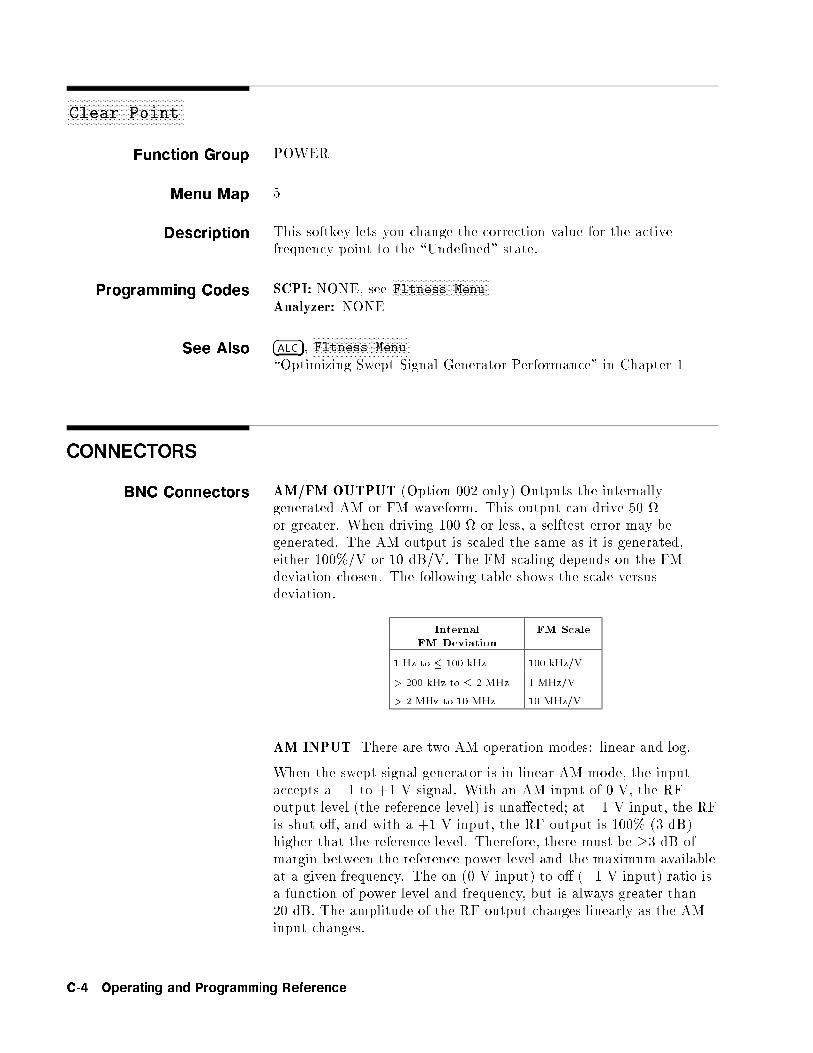
aaaaaaaaaaaaaaaaaaaaaaaaaaaaaaaaaaaaaaaaaaaaaaClear Point
Function Group POWER
Menu Map 5
Description This softkey lets you change the correction value for the activefrequency point to the \Unde�ned" state.
Programming Codes SCPI: NONE, seeNNNNNNNNNNNNNNNNNNNNNNNNNNNNNNNNNNNNNNFltness Menu
Analyzer: NONE
See Also �ALC�,NNNNNNNNNNNNNNNNNNNNNNNNNNNNNNNNNNNNNNFltness Menu
\Optimizing Swept Signal Generator Performance" in Chapter 1
CONNECTORS
BNC Connectors AM/FM OUTPUT (Option 002 only) Outputs the internally-generated AM or FM waveform. This output can drive 50 or greater. When driving 100 or less, a selftest error may begenerated. The AM output is scaled the same as it is generated,either 100%/V or 10 dB/V. The FM scaling depends on the FMdeviation chosen. The following table shows the scale versusdeviation.
Internal
FM Deviation
FM Scale
1 Hz to � 100 kHz 100 kHz/V
> 200 kHz to � 2 MHz 1 MHz/V
> 2 MHz to 10 MHz 10 MHz/V
AM INPUT There are two AM operation modes: linear and log.
When the swept signal generator is in linear AM mode, the inputaccepts a �1 to +1 V signal. With an AM input of 0 V, the RFoutput level (the reference level) is una�ected; at �1 V input, the RFis shut o�, and with a +1 V input, the RF output is 100% (3 dB)higher that the reference level. Therefore, there must be �3 dB ofmargin between the reference power level and the maximum availableat a given frequency. The on (0 V input) to o� (�1 V input) ratio isa function of power level and frequency, but is always greater than20 dB. The amplitude of the RF output changes linearly as the AMinput changes.
C-4 Operating and Programming Reference
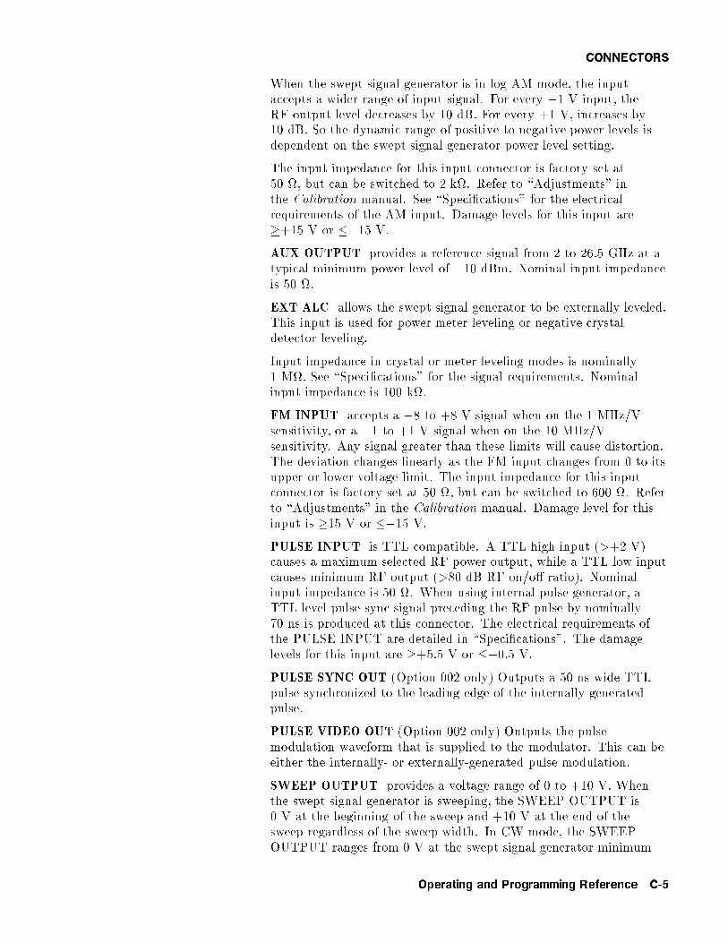
CONNECTORS
When the swept signal generator is in log AM mode, the inputaccepts a wider range of input signal. For every �1 V input, theRF output level decreases by 10 dB. For every +1 V, increases by10 dB. So the dynamic range of positive to negative power levels isdependent on the swept signal generator power level setting.
The input impedance for this input connector is factory set at50 , but can be switched to 2 k. Refer to \Adjustments" inthe Calibration manual. See \Speci�cations" for the electricalrequirements of the AM input. Damage levels for this input are�+15 V or ��15 V.
AUX OUTPUT provides a reference signal from 2 to 26.5 GHz at atypical minimum power level of �10 dBm. Nominal input impedanceis 50 .
EXT ALC allows the swept signal generator to be externally leveled.This input is used for power meter leveling or negative crystaldetector leveling.
Input impedance in crystal or meter leveling modes is nominally1 M. See \Speci�cations" for the signal requirements. Nominalinput impedance is 100 k.
FM INPUT accepts a �8 to +8 V signal when on the 1 MHz/Vsensitivity, or a �1 to +1 V signal when on the 10 MHz/Vsensitivity. Any signal greater than these limits will cause distortion.The deviation changes linearly as the FM input changes from 0 to itsupper or lower voltage limit. The input impedance for this inputconnector is factory set at 50 , but can be switched to 600 . Referto \Adjustments" in the Calibration manual. Damage level for thisinput is �15 V or ��15 V.
PULSE INPUT is TTL compatible. A TTL high input (>+2 V)causes a maximum selected RF power output, while a TTL low inputcauses minimum RF output (>80 dB RF on/o� ratio). Nominalinput impedance is 50 . When using internal pulse generator, aTTL-level pulse sync signal preceding the RF pulse by nominally70 ns is produced at this connector. The electrical requirements ofthe PULSE INPUT are detailed in \Speci�cations". The damagelevels for this input are �+5.5 V or ��0.5 V.
PULSE SYNC OUT (Option 002 only) Outputs a 50 ns wide TTLpulse synchronized to the leading edge of the internally-generatedpulse.
PULSE VIDEO OUT (Option 002 only) Outputs the pulsemodulation waveform that is supplied to the modulator. This can beeither the internally- or externally-generated pulse modulation.
SWEEP OUTPUT provides a voltage range of 0 to +10 V. Whenthe swept signal generator is sweeping, the SWEEP OUTPUT is0 V at the beginning of the sweep and +10 V at the end of thesweep regardless of the sweep width. In CW mode, the SWEEPOUTPUT ranges from 0 V at the swept signal generator minimum
Operating and Programming Reference C-5
CONNECTORS
frequency to +10 V at the speci�ed maximum frequency, with aproportional voltage for frequencies between the speci�ed minimumand maximum. When the swept signal generator is in manual sweepoperation the sweep output voltage is a percentage of the span.Minimum load impedance is 3 k.
STOP SWEEP IN/OUT stops a sweep when this input is pulledlow. Retrace does not occur, and the sweep resumes when thisinput is pulled high. The open circuit voltage is TTL high and isinternally pulled low when the swept signal generator stops its sweep.Externally forcing this input high will not cause damage or disruptnormal operation.
10 MHz REF INPUT accepts a 10 MHz �100 Hz, 0 to +10 dBmreference signal for operation referenced to an external time base.Nominal input impedance is 50 .
10 MHz REF OUTPUT provides a 0 dBm, 10 MHz signal derivedfrom the internal frequency standard of the swept signal generator.This input is a 50 connector that can be used as the master clockreference output for a network of instruments.
TRIGGER INPUT activated on a TTL rising edge. Used toexternally initiate an analog sweep or to advance to the next point ofa step list or a frequency list.
TRIGGER OUTPUT Produces a 1 �s wide TTL-level pulse at 1601points evenly spaced across an analog sweep, or at each point in astep list or a frequency list.
VOLTS/GHz supplies a voltage that is proportional to the RFoutput frequency, with a ratio of 0.5 volt output for every 1 GHz ofRF frequency (factory setting). This ratio is switchable to either0.25 or 1 volt. The switch is located on the A12 SYTM assembly, seeAdjustments in the Agilent Technologies 8360 B-Series Swept SignalGenerator/8360 L-Series Swept CW Generator Service Guide forinformation. This output is designed to drive into 2 k or greater.
Z-AXIS BLANK/MKRS supplies a positive rectangular pulse(approximately +5 V into 2 k) during the retrace and switchpoints when the swept signal generator is sweeping. This outputalso supplies a �5 V pulse when the RF output is coincident with amarker frequency.
Multi-pin Connectors AUXILIARY INTERFACE connector provides control signals tothe HP/Agilent 8516A S-parameter test set switch doubler. Thisconnector is a 25-pin D-subminiature receptacle located on the rearpanel. It is also used for dual swept signal generator measurementsystems (two-tone systems), refer to
NNNNNNNNNNNNNNNNNNNNNNNNNNNNNNNNNNNNNNNNNNNNNNNNNNNNNNNNNNNStep Control Master for more
information.
C-6 Operating and Programming Reference
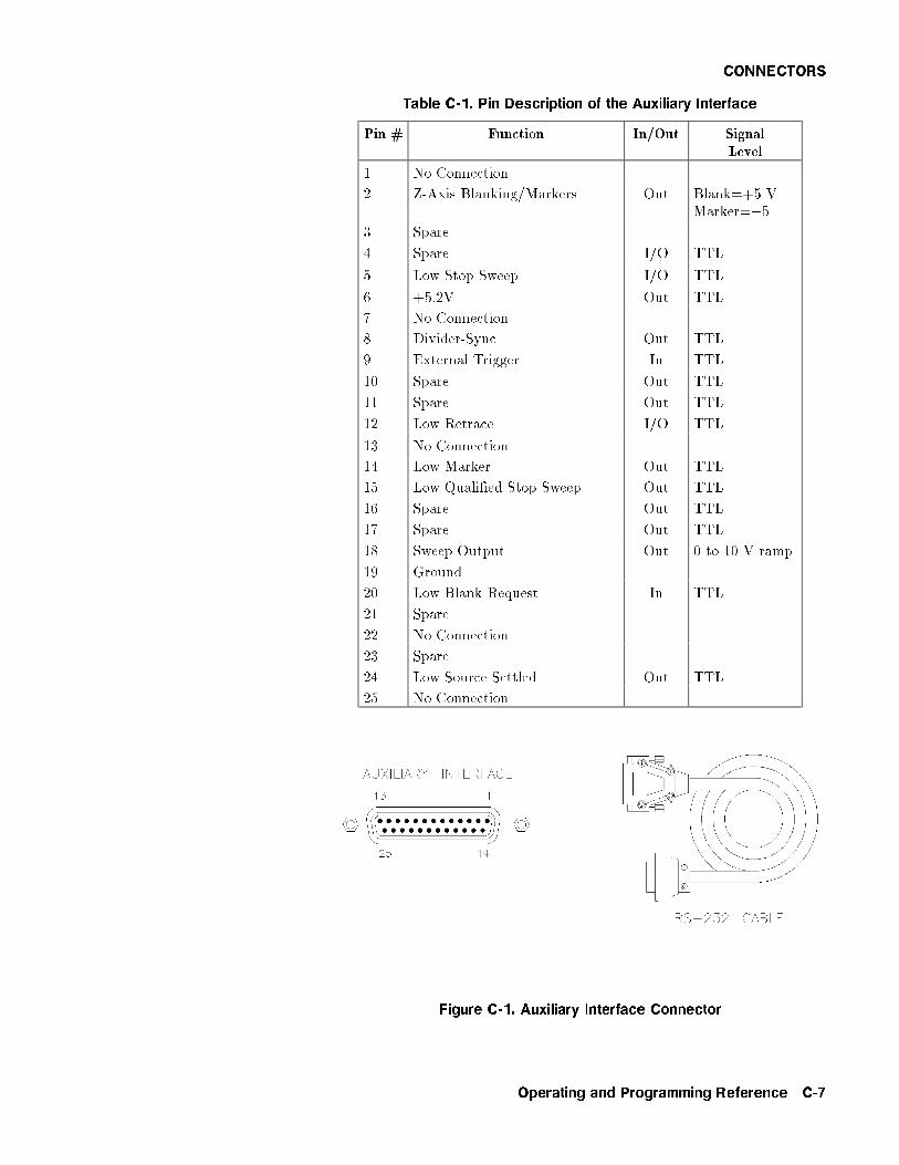
CONNECTORS
Table C-1. Pin Description of the Auxiliary Interface
Pin # Function In/Out SignalLevel
1 No Connection
2 Z-Axis Blanking/Markers Out Blank=+5 VMarker=�5
3 Spare
4 Spare I/O TTL
5 Low Stop Sweep I/O TTL
6 +5.2V Out TTL
7 No Connection
8 Divider-Sync Out TTL
9 External Trigger In TTL
10 Spare Out TTL
11 Spare Out TTL
12 Low Retrace I/O TTL
13 No Connection
14 Low Marker Out TTL
15 Low Quali�ed Stop Sweep Out TTL
16 Spare Out TTL
17 Spare Out TTL
18 Sweep Output Out 0 to 10 V ramp
19 Ground
20 Low Blank Request In TTL
21 Spare
22 No Connection
23 Spare
24 Low Source Settled Out TTL
25 No Connection
Figure C-1. Auxiliary Interface Connector
Operating and Programming Reference C-7
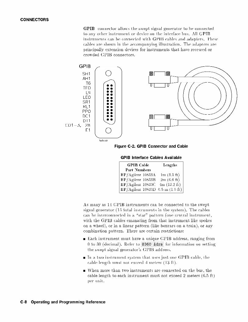
CONNECTORS
GPIB connector allows the swept signal generator to be connectedto any other instrument or device on the interface bus. All GPIBinstruments can be connected with GPIB cables and adapters. Thesecables are shown in the accompanying illustration. The adapters areprincipally extension devices for instruments that have recessed orcrowded GPIB connectors.
Figure C-2. GPIB Connector and Cable
GPIB Interface Cables Available
GPIB CablePart Numbers
Lengths
HP/Agilent 10833A 1m (3.3 ft)HP/Agilent 10833B 2m (6.6 ft)HP/Agilent 10833C 4m (13.2 ft)HP/Agilent 10833D 0.5 m (1.6 ft)
As many as 14 GPIB instruments can be connected to the sweptsignal generator (15 total instruments in the system). The cablescan be interconnected in a \star" pattern (one central instrument,with the GPIB cables emanating from that instrument like spokeson a wheel), or in a linear pattern (like boxcars on a train), or anycombination pattern. There are certain restrictions:
Each instrument must have a unique GPIB address, ranging from0 to 30 (decimal). Refer to
NNNNNNNNNNNNNNNNNNNNNNNNNNNNN8360 Adrs for information on setting
the swept signal generator's GPIB address.
In a two-instrument system that uses just one GPIB cable, thecable length must not exceed 4 meters (13 ft).
When more than two instruments are connected on the bus, thecable length to each instrument must not exceed 2 meters (6.5 ft)per unit.
C-8 Operating and Programming Reference

CONNECTORS
The total cable length between all units must not exceed 20 meters(65 ft).
Agilent Technologies manufactures GPIB extender instruments(HP/Agilent models 37201A, 37204A/B) that overcome the rangelimitations imposed by the cabling rules. These extenders allowtwin-pair cable operation up 1 km (3,280 ft), and telephone modemoperation over any distance. Agilent Technologies Sales and Serviceo�ces can provide additional information on the GPIB extenders.
The codes next to the GPIB connector, illustrated in Figure C-2,describe the GPIB electrical capabilities of the swept signalgenerator, using IEEE Std. 488-1978 mnemonics (GPIB, GP-IB,IEEE-488, and IEC-625 are all electrically equivalent). Brie y, themnemonics translate as follows:
SH1 Source Handshake, complete capability.
AH1 Acceptor Handshake, complete capability.
T6: Talker; capable of basic talker, serial poll, andunaddress if MLA.
TEO Talker, Extended address; no capability.
L4 Listener, capable of basic listener, and unaddress ifMTA.
LEO Listener, Extended address; no capability.
SR1 Service Request, complete capability.
RL1 Remote Local, complete capability.
PPO Parallel Poll, no capability.
DC1 Device Clear, complete capability.
DT1 Device Trigger, complete capability.
CO, 1, 2, 3, 28 Controller capability options; CO, no capabilities;C1, system controller; C2, send IFC and take charge;C3, send REN; C28, send I. F. messages.
E1 Electrical speci�cation indicating open collectoroutputs.
These codes are described completely in the IEEE Std 488-1978document, published by The Institute of Electrical and ElectronicEngineers, Inc., 345 East 47th Street, New York, New York 11017.
SOURCE MODULE INTERFACE sends and receives digitaland analog signals to and from an HP/Agilent 83550-Seriesmillimeter-wave source module. With the source module connected,the swept signal generator assumes the characteristics of the sourcemodule. Refer to
NNNNNNNNNNNNNNNNNNNNNNNNNNNNNNNNNNNNNNNNNNNNNNNNNNNNNNNNNNNNNNNNNLeveling Point Module for more information.
Operating and Programming Reference C-9
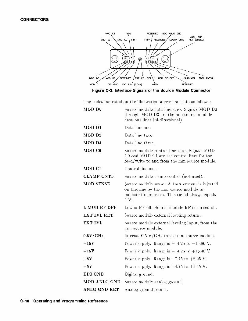
CONNECTORS
Figure C-3. Interface Signals of the Source Module Connector
The codes indicated on the illustration above translate as follows:
MOD D0 Source module data line zero. Signals MOD D0through MOD D3 are the mm source moduledata bus lines (bi-directional).
MOD D1 Data line one.
MOD D2 Data line two.
MOD D3 Data line three.
MOD C0 Source module control line zero. Signals MODC0 and MOD C1 are the control lines for theread/write to and from the mm source module.
MOD C1 Control line one.
CLAMP CNTL Source module clamp control (not used).
MOD SENSE Source module sense. A 1mA current is injectedon this line by the mm source module toindicate its presence. This signal always equals0 V.
L MOD RF OFF Low = RF o�. Source module RF is turned o�.
EXT LVL RET Source module external leveling return.
EXT LVL Source module external leveling input, from themm source module.
0.5V/GHz Internal 0.5 V/GHz to the mm source module.
�15V Power supply. Range is �14.25 to �15.90 V.
+15V Power supply. Range is +14.25 to +16.40 V
+8V Power supply. Range is +7.75 to +8.25 V.
+5V Power supply. Range is +4.75 to +5.45 V.
DIG GND Digital ground.
MOD ANLG GND Source module analog ground.
ANLG GND RET Analog ground return.
C-10 Operating and Programming Reference

�CONT�
RF Output Connector The swept signal generator is equipped with a precision 3.5 mm maleconnector (2.4 mm male connector on 40 GHz models). The outputimpedance, SWR and other electrical characteristics are listed in\Speci�cations". When making connections, carefully align the centerconductor elements, then rotate the knurled barrel while the matingcomponent remains still. Tighten until �rm contact is made.
Take care when working with either of these connectors. If thisconnector is mechanically degraded in any way, high frequency lossesoccur. Refer to Application Note 326, Connector Care, for moreinformation.
�CONT�
Function Group SWEEP
Menu Map 7
Description This hardkey initiates continuous sweep-retrace cycling of theswept signal generator. The sweep is initiated by one of the triggerfunctions, while the sweep speed is controlled by the sweep timefunction. The green LED located above this key lights when theswept signal generator is performing an list, step, or analog sweep.
The LED is o� during all of the following: retrace, band crossings,phase locking at the start frequency of each new sweep and duringmanual sweeps.
Programming Codes SCPI: INITiate:CONTinuous ONj1Analyzer: S1
See AlsoNNNNNNNNNNNNNNNNNNNNNNNNNNNNNNNNNNNNNNManual Sweep , �SINGLE�\Continuous, Single, and Manual Sweep Operation" in Chapter 1\Programming Typical Measurements" in Chapter 1
Operating and Programming Reference C-11
aaaaaaaaaaaaaaaaaaaaaaaaaaaaaaaaaaaaaaCopy List
Function Group POWER
Menu Map 5
Description This softkey lets you copy the frequency information of the frequencylist to the atness correction menu. If there is no frequency list tocopy, nothing happens.
Programming Codes SCPI: NONE, seeNNNNNNNNNNNNNNNNNNNNNNNNNNNNNNNNNNNNNNFltness Menu
Analyzer: NONE
See Also �ALC�,NNNNNNNNNNNNNNNNNNNNNNNNNNNNNNNNNNNNNNFltness Menu
aaaaaaaaaaaaaaaaaaaaaaaaaaaaaaaaaaaaaaaaaaaaaaaaaaaaaaaaaaaaaCorPair Disable
Function Group POWER
Menu Map 5
Description This softkey lets you disable the user atness array (frequency-correction pairs) so that the 1601 point atness array will be appliedwhen �FLTNESS ON/OFF� is on. The 1601 point atness array isaccessible only through the GPIB interface.
Programming Codes SCPI: CORRection:SOURce[0j1] ARRayAnalyzer: NONE
See AlsoNNNNNNNNNNNNNNNNNNNNNNNNNNNNNNNNNNNNNNFltness Menu
\Optimizing Swept Signal Generator Performance" in Chapter 1
C-12 Operating and Programming Reference

�CW�
aaaaaaaaaaaaaaaaaaaaaaaaaaaaaaaaaaaaaaaaaaaaaaaaaaaaaaaaaaaaaCoupling Factor
Function Group ALC
Menu Map 1
Description This softkey allows speci�cation of the coupling factor of an externalcoupler/detector used to externally level the swept signal generatoroutput power. Negative coupling factor values are required for validentry. See \Speci�cations" for the coupling factor range.
Programming Codes SCPI: POWer:ALC:CFACtor <num>[dB]jMAXimumjMINimumAnalyzer: NONE
See Also �ALC�\Externally Leveling the Swept Signal Generator" in Chapter 1
�CW�
Function Group FREQUENCY
Menu Map 2
Description This hardkey lets you select a synthesized continuous wave frequency.When you press �CW�, the swept signal generator stops sweeping(green SWEEP LED o�) and displays: --> CW: XXXXX MHz,where XXXXX represents a frequency value. Use either the rotaryknob, the step keys (with or without the left/right arrow keys), orthe numerical entry keys with a terminator key to set the desiredvalue. If a small change is desired, use the left and right arrow keysto underline the digit to be changed.
Programming Codes SCPI:
FREQuency[:CW] <num>[freq su�x] orMAXimumjMINimumjUPjDOWNFREQuency:MODE CW
Analyzer: CW
See AlsoNNNNNNNNNNNNNNNNNNNNNNNNNNNNNNNNNNNNNNNNNCW/CF Coupled , �START�, �STOP�\CW Operation and Start/Stop Frequency Sweep" in Chapter 1\Programming Typical Measurements" in Chapter 1
Operating and Programming Reference C-13

aaaaaaaaaaaaaaaaaaaaaaaaaaaaaaaaaaaaaaaaaaaaaaaaaaaaaaCW/CF Coupled
Function Group FREQUENCY
Menu Map 2
Description This softkey couples the CW function to the center frequencyfunction. Any change initiated in either one of these parameterscauses a change in the other.
Programming Codes SCPI: FREQuency:CW:AUTO ONjOFFj1j0Analyzer: NONE
See Also �CENTER�, �CW�
C-14 Operating and Programming Reference

D
aaaaaaaaaaaaaaaaaaaaaaaaaaaaaaaaaaaaaaaaaaaaaaaaaaaaaaDblr Amp Menu
Function Group POWER
Menu Map 5
Description This softkey accesses the doubler amp mode softkeys. These softkeysare applicable to instrument models with a doubler installed. Thedoubler has an integral ampli�er whose operation is controlled by theinstrument �rmware. Its use depends on the frequency of operationand on the calibration constants set at the factory. The instrumentdefaults after preset to this automatic mode of operation which isthe speci�ed operation. Softkeys in this menu will allow you to turnthe doubler ampli�er always on or always o�. These two modes areunspeci�ed operation for instruments with a doubler installed. Thesesoftkeys have no e�ect on instruments without a doubler.NNNNNNNNNNNNNNNNNNNNNNNNNNNNNNNNNNNNNNNNNNNNNNNNNNNNNNNNNNNNNNNNNDoubler Amp Mode AUTO Sets the doubler amp mode to
AUTO. This is the default afterpreset and must be used for speci�edperformance.NNNNNNNNNNNNNNNNNNNNNNNNNNNNNNNNNNNNNNNNNNNNNNNNNNNNNNNNNNN
Doubler Amp Mode On Turns the doubler ampli�er onregardless of the frequency ofoperation. Using this mode results inunspeci�ed performance.NNNNNNNNNNNNNNNNNNNNNNNNNNNNNNNNNNNNNNNNNNNNNNNNNNNNNNNNNNNNNN
Doubler Amp Mode Off Turns the doubler ampli�er o�regardless of the frequency ofoperation. Using this mode results inunspeci�ed performance.
Programming Codes SCPI: NONEAnalyzer: NONE
See Also Softkeys listed above.
Operating and Programming Reference D-1
aaaaaaaaaaaaaaaaaaaaaaaaaaaaaaDeep AM
Function Group MODULATION
Menu Map 4
Description This softkey activates distortion reduction mode for deep AMoperation. Deep AM automatically switches to the ALC o� levelingmode when the modulation level drives the \detector-logger" (partof the RF components, see Figure A-1) below its detection range.The modulated waveform is DC coupled and ALC leveled above�13 dBm. Below �13 dBm the waveform is DC controllable but notALC leveled, and is subject to drift of typically �0.25 dB/s. Thisvalue is reduced by a factor of 10 if the low ALC bandwidth featureis selected. An asterisk next to the key label indicates that thisfeature is active.
Programming Codes SCPI:
AM:MODE DEEPAM:STATe ONjOFFj1j0
Analyzer: NONE
See Also �ALC�,NNNNNNNNNNNNNNNNNNNNNNNNNNNNNAM On/Off , �MOD�
\Optimizing Swept Signal Generator Performance" in Chapter 1
aaaaaaaaaaaaaaaaaaaaaaaaaaaaaaaaaaaaaaaaaaDelay Menu
Function Group �MOD�
Menu Map 4
Description This softkey (Option 002 only) accesses the pulse delay softkeys.These softkeys let you delay the internally generated pulsed outputfrom either the PULSE SYNC OUT signal or from the external pulsesignal at the PULSE input.NNNNNNNNNNNNNNNNNNNNNNNNNNNNNNNNNNNNNNNNNNNNNNNNNNNNNNNNPulse Delay Normal Delays the output pulse from the
PULSE SYNC OUT signal.NNNNNNNNNNNNNNNNNNNNNNNNNNNNNNNNNNNNNNNNNNNNNNNNNNNNNNNNPulse Delay Trig'd Delays the output pulse from the
PULSE input.
D-2 Operating and Programming Reference

NNNNNNNNNNNNNNNNNNNNNNNNNNNNNDelete All
Programming Codes SCPI: NONEAnalyzer: NONE
See Also �MOD�, also see \Modulation" and \Pulse".
aaaaaaaaaaaaaaaaaaaaaaaaaaaaaaaaaaaaaaaaaaaaaaDelete Menu
Function Group FREQUENCY, POWER
Menu Map 2, 5
Description In the menu structure there are two occurrences of this softkey. Itleads to the delete choices for both the frequency list menu and thepower atness menu.NNNNNNNNNNNNNNNNNNNNNNNNNNNNNNNNDelete All Deletes the complete array.
NNNNNNNNNNNNNNNNNNNNNNNNNNNNNNNNNNNNNNNNNNNNDelete Current Deletes the active line in the array.
NNNNNNNNNNNNNNNNNNNNNNNNNNNNNNNNNNNNNNDelete Undef Appears in the power atness menu only. It
deletes the points that are unde�ned.
Programming Codes SCPI: NONE, seeNNNNNNNNNNNNNNNNNNNNNNNNNNNNNNNNNNNNNNFltness Menu or
NNNNNNNNNNNNNNNNNNNNNNNNNNNNNList Menu
Analyzer: NONE
See AlsoNNNNNNNNNNNNNNNNNNNNNNNNNNNNNNNNNNNNNNFltness Menu ,
NNNNNNNNNNNNNNNNNNNNNNNNNNNNNList Menu
\Optimizing Swept Signal Generator Performance" in Chapter 1
aaaaaaaaaaaaaaaaaaaaaaaaaaaaaaaaaaaaaaaaaaDelete All
Function Group FREQUENCY, POWER
Menu Map 2, 5
Operating and Programming Reference D-3
NNNNNNNNNNNNNNNNNNNNNNNNNNNNNDelete All
Description In the menu structure there are two occurrences of this softkey. Oneoccurs in the frequency list menu. The other occurs in the power atness menu.
In the both applications, this softkey lets you delete all entries in thearray with one keystroke.
Programming Codes SCPI: NONE, seeNNNNNNNNNNNNNNNNNNNNNNNNNNNNNNNNNNNNNNFltness Menu or
NNNNNNNNNNNNNNNNNNNNNNNNNNNNNList Menu
Analyzer: NONE
See AlsoNNNNNNNNNNNNNNNNNNNNNNNNNNNNNNNNNNNNNNFltness Menu ,
NNNNNNNNNNNNNNNNNNNNNNNNNNNNNList Menu
\Optimizing Swept Signal Generator Performance" in Chapter 1
aaaaaaaaaaaaaaaaaaaaaaaaaaaaaaaaaaaaaaaaaaaaaaaaaaaaaaaaaDelete Current
Function Group FREQUENCY, POWER
Menu Map 2, 5
Description In the menu structure there are two occurrences of this softkey. Oneoccurs in the frequency list menu. The other occurs in the power atness menu.
In the list menu application, the frequency entry and the associatedo�set and dwell values in the active line are deleted. The active lineis designated by the --> pointer and can be pointing at any of valueswithin the array.
In the atness menu application, the frequency and associatedcorrection value in the active line is deleted. The active line pointer--> can be pointing to either the frequency value or the correctionvalue.
Programming Codes SCPI: NONE, seeNNNNNNNNNNNNNNNNNNNNNNNNNNNNNNNNNNNNNNFltness Menu or
NNNNNNNNNNNNNNNNNNNNNNNNNNNNNList Menu
Analyzer: NONE
See AlsoNNNNNNNNNNNNNNNNNNNNNNNNNNNNNNNNNNNNNNFltness Menu ,
NNNNNNNNNNNNNNNNNNNNNNNNNNNNNList Menu
D-4 Operating and Programming Reference

NNNNNNNNNNNNNNNNNNNNNNNNNNNNNNNNNNNDelta Marker
aaaaaaaaaaaaaaaaaaaaaaaaaaaaaaaaaaaaaaaaaaaaaaaaaaDelete Undef
Function Group POWER
Menu Map 5
Description This softkey occurs in the power atness menu. It lets you deleteonly those points that are unde�ned. Unde�ned correction values arenoted by the display as Undefined.
Programming Codes SCPI: NONE, seeNNNNNNNNNNNNNNNNNNNNNNNNNNNNNNNNNNNNNNFltness Menu
Analyzer: NONE
See AlsoNNNNNNNNNNNNNNNNNNNNNNNNNNNNNNNNNNNNNNFltness Menu
aaaaaaaaaaaaaaaaaaaaaaaaaaaaaaaaaaaaaaaaaaaaaaaaaaDelta Marker
Function Group MARKER
Menu Map 3
Description This softkey causes the di�erence in frequency between two markersto appear on the swept signal generator display. The frequencydi�erence is indicated in the following format: --> DELTA MARKER
|m - n| XXXXX MHz, where m= the last marker activated, n= thereference marker, and XXXXX represents some frequency value.On a CRT display, the trace between the two selected markers isintensi�ed. An asterisk next to the key label indicates that thisfeature is active.
At preset (factory), the swept signal generator is set to measure thedi�erence between M2 and M1 (marker reference). If markers have
not been activated after preset, selectingNNNNNNNNNNNNNNNNNNNNNNNNNNNNNNNNNNNNNNDelta Marker indicates
the di�erence between M2 and M1. Both of these markers have anasterisk next to their key label, indicating that they are on.
WheneverNNNNNNNNNNNNNNNNNNNNNNNNNNNNNNNNNNNNNNDelta Marker is selected, it reactivates the last marker
selected and makes that marker the \m" frequency. If the deltamarker feature is active, selecting a marker causes the \m" frequencyto change to the marker selected. If a frequency entry is made whendelta marker is in the active entry area, the frequency value of the\m" frequency is changed to the new frequency entry causing thenew di�erence in frequency to be displayed. Negative frequencydi�erences are possible if \n" is greater than \m".
Operating and Programming Reference D-5
NNNNNNNNNNNNNNNNNNNNNNNNNNNNNNNNNNNDelta Marker
Programming Codes SCPI: MARKer[n]:DELTa? <num>, <num>Analyzer: MD1 function on, MD0 function o�
See Also �MARKER�\Marker Operation" in Chapter 1\Programming Typical Measurements" in Chapter 1
aaaaaaaaaaaaaaaaaaaaaaaaaaaaaaaaaaaaaaaaaaaaaaaaaaaaaaDelta Mkr Ref
Function Group MARKER
Menu Map 3
Description This softkey displays the �ve markers available as the delta markerreference. The delta marker frequency is calculated using theequation:
f�m=fm�fmref
where fm is the frequency of the active marker and fmref is thefrequency of the reference marker.
Programming Codes SCPI: MARKer:REFerenc <marker number>Analyzer: MD1 function on, MD0 function o�.
See AlsoNNNNNNNNNNNNNNNNNNNNNNNNNNNNNNNNNNNNNNDelta Marker
\Marker Operation" in Chapter 1\Programming Typical Measurements" in Chapter 1
D-6 Operating and Programming Reference
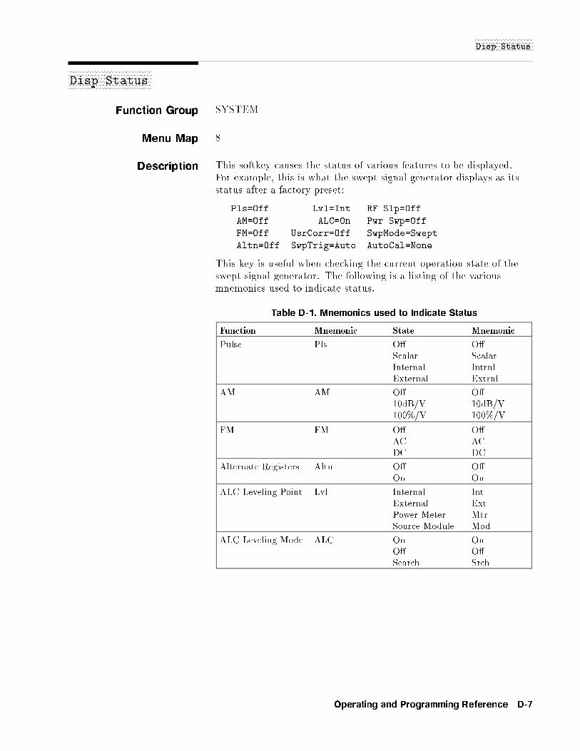
NNNNNNNNNNNNNNNNNNNNNNNNNNNNNNNNDisp Status
aaaaaaaaaaaaaaaaaaaaaaaaaaaaaaaaaaaaaaaaaaaaaaDisp Status
Function Group SYSTEM
Menu Map 8
Description This softkey causes the status of various features to be displayed.For example, this is what the swept signal generator displays as itsstatus after a factory preset:
Pls=Off Lvl=Int RF Slp=Off
AM=Off ALC=On Pwr Swp=Off
FM=Off UsrCorr=Off SwpMode=Swept
Altn=Off SwpTrig=Auto AutoCal=None
This key is useful when checking the current operation state of theswept signal generator. The following is a listing of the variousmnemonics used to indicate status.
Table D-1. Mnemonics used to Indicate Status
Function Mnemonic State Mnemonic
Pulse Pls O� O�Scalar ScalarInternal IntrnlExternal Extrnl
AM AM O� O�10dB/V 10dB/V100%/V 100%/V
FM FM O� O�AC ACDC DC
Alternate Registers Altn O� O�On On
ALC Leveling Point Lvl Internal IntExternal ExtPower Meter MtrSource Module Mod
ALC Leveling Mode ALC On OnO� O�Search Srch
Operating and Programming Reference D-7
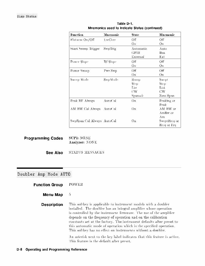
NNNNNNNNNNNNNNNNNNNNNNNNNNNNNNNNDisp Status
Table D-1.
Mnemonics used to Indicate Status (continued)
Function Mnemonic State Mnemonic
Flatness On/O� UsrCorr O� O�On On
Start Sweep Trigger SwpTrig Automatic AutoGPIB BusExternal Ext
Power Slope Rf Slope O� O�On On
Power Sweep Pwr Swp O� O�On On
Sweep Mode SwpMode Ramp SweptStep StepList ListCW CWSpan=0 Zero Span
Peak RF Always AutoCal On Peaking orPeak
AM BW Cal Always AutoCal On AM BW orAmBw orAm
SwpSpan Cal Always AutoCal On SweptFreq orFreq or Frq
Programming Codes SCPI: NONEAnalyzer: NONE
See Also STATUS MESSAGES
aaaaaaaaaaaaaaaaaaaaaaaaaaaaaaaaaaaaaaaaaaaaaaaaaaaaaaaaaaaaaaaaaaaaaaaaaaaaaaaaaaaaaDoubler Amp Mode AUTO
Function Group POWER
Menu Map 5
Description This softkey is applicable to instrument models with a doublerinstalled. The doubler has an integral ampli�er whose operationis controlled by the instrument �rmware. The use of the ampli�erdepends on the frequency of operation and on the calibrationconstants set at the factory. The instrument defaults after preset tothis automatic mode of operation which is the speci�ed operation.This softkey has no e�ect on instruments without a doubler.
An asterisk next to the key label indicates that this feature is active.This feature is the default after preset.
D-8 Operating and Programming Reference

NNNNNNNNNNNNNNNNNNNNNNNNNNNNNNNNNNNNNNNNNNNNNNNNNNNNNNNNDoubler Amp Mode Off
Programming Codes SCPI:
POWer:AMPLi�er:STATE:AUTO ONjOFFj0j1POWer:AMPLi�er:STATE:AUTO?
Analyzer: NONE
See AlsoNNNNNNNNNNNNNNNNNNNNNNNNNNNNNNNNNNNNNNNNNDblr Amp Menu
aaaaaaaaaaaaaaaaaaaaaaaaaaaaaaaaaaaaaaaaaaaaaaaaaaaaaaaaaaaaaaaaaaaaaaaaaaaaaaaaaDoubler Amp Mode Off
Function Group POWER
Menu Map 5
Description This softkey is applicable to instrument models with a doublerinstalled. The doubler has an integral ampli�er whose operation iscontrolled by the instrument �rmware. This softkey turns o� theautomatic mode of operation and turns o� the ampli�er so that it isnever used. This is an unspeci�ed mode of operation since the outputpower may not be at the maximum leveled output power speci�cationat frequencies generated in the doubled mode. This softkey has noe�ect on instruments without a doubler.
An asterisk next to the key label indicates that this feature is active.
Programming Codes SCPI:
POWer:AMPLi�er:STATE ONjOFFj0j1POWer:AMPLi�er:STATE?
Analyzer: NONE
See AlsoNNNNNNNNNNNNNNNNNNNNNNNNNNNNNNNNNNNNNNNNNDblr Amp Menu
Operating and Programming Reference D-9

aaaaaaaaaaaaaaaaaaaaaaaaaaaaaaaaaaaaaaaaaaaaaaaaaaaaaaaaaaaaaaaaaaaaaaaaaaaaaDoubler Amp Mode On
Function Group POWER
Menu Map 5
Description This softkey is applicable to instrument models with a doublerinstalled. The doubler has an integral ampli�er whose operation iscontrolled by the instrument �rmware. This softkey turns o� theautomatic mode of operation and turns on the ampli�er so that it isalways used. This is an unspeci�ed mode of operation since it cancause increased harmonics and degraded dynamic range at somefrequencies. This softkey has no e�ect on instruments without adoubler.
An asterisk next to the key label indicates that this feature is active.
Programming Codes SCPI:
POWer:AMPLi�er:STATE ONjOFFj0j1POWer:AMPLi�er:STATE?
Analyzer: NONE
See AlsoNNNNNNNNNNNNNNNNNNNNNNNNNNNNNNNNNNNNNNNNNDblr Amp Menu
aaaaaaaaaaaaaaaaaaaaaaaaaaaaaaaaaaaaaaaaaaaaaaaaaaaaaaDwell Coupled
Function Group FREQUENCY
Menu Map 2
Description This softkey lets you couple the dwell time for points in the steppedfrequency sweep mode to the ramp sweep mode sweep time. Theequation to determine the dwell time in the dwell coupled mode is asfollows:Coupled Dwell Time = (sweep time) � (number of step points)
An asterisk next to the key label indicates that this feature is active.
Programming Codes SCPI: SWEep[:FREQuency]:DWEL1:AUTO ONj1Analyzer: NONE
See AlsoNNNNNNNNNNNNNNNNNNNNNNNNNNNNNNNNNNNNNNNNNStep Swp Menu
D-10 Operating and Programming Reference

E
aaaaaaaaaaaaaaaaaaaaaaaaaaaaaaaaaaaaaa8360 Adrs
Function Group SYSTEM
Menu Map 8
Description This softkey lets you change the GPIB address of the swept signalgenerator. Enter the address desired using the numeric entry keysor the up/down arrow keys. The address value may be set between0 and 30. The swept signal generator stores the address valuein non-volatile memory. The default address of the swept signalgenerator is 19.
Programming Codes SCPI: SYSTem:COMMunicate:GPIB:ADDRessAnalyzer: NONE
See Also Connectors,NNNNNNNNNNNNNNNNNNNNNNNNNNNNNGPIB Menu
\Instrument Addresses" in Chapter 1\Programming Typical Measurements" in Chapter 1
Operating and Programming Reference E-1

aaaaaaaaaaaaaaaaaaaaaaaaaaaaaaaaaaaaaaaaaaEnter Corr
Function Group POWER
Menu Map 5
Description This softkey lets you enter a power correction value for a frequencypoint in the atness array. A frequency point must be entered beforea correction value can be accepted, otherwise the following errormessage appears:
ERROR - Must first enter correction freq.
The up/down arrow keys let you scroll through the frequency pointsavailable for power correction. If no correction value is enteredfor a frequency point, the swept signal generator display indicatesUndefined. The range of acceptable values is �40 to +40 dB. Anasterisk next to the key label indicates that this feature is active.
Programming Codes SCPI: NONE, seeNNNNNNNNNNNNNNNNNNNNNNNNNNNNNNNNNNNNNNFltness Menu
Analyzer: NONE
See AlsoNNNNNNNNNNNNNNNNNNNNNNNNNNNNNNNNNNNNNNFltness Menu
\Optimizing Swept Signal Generator Performance" in Chapter 1
E-2 Operating and Programming Reference

NNNNNNNNNNNNNNNNNNNNNNNNNNNNNEnter Freq
aaaaaaaaaaaaaaaaaaaaaaaaaaaaaaaaaaaaaaaaaaEnter Freq
Function Group POWER
Menu Map 5
Description This softkey lets you enter a frequency point into the atnesscorrection array. When the Power
NNNNNNNNNNNNNNNNNNNNNNNNNNNNNNNNNNNNNNFltness Menu is selected,NNNNNNNNNNNNNNNNNNNNNNNNNNNNNNNN
Enter Freq is automatically activated. Frequency points must beentered before correction values can be accepted into the array.Frequency points can be entered in any order, and the swept signalgenerator automatically reorders them beginning with the lowestfrequency. One frequency-correction pair is the minimum and 801 isthe maximum number of points that can be entered. An asterisknext to the key label indicates that this feature is active.
Programming Codes SCPI: NONE, seeNNNNNNNNNNNNNNNNNNNNNNNNNNNNNNNNNNNNNNFltness Menu
Analyzer:NONE
See AlsoNNNNNNNNNNNNNNNNNNNNNNNNNNNNNNNNNNNNNNFltness Menu
\Optimizing Swept Signal Generator Performance" in Chapter 1
Operating and Programming Reference E-3
aaaaaaaaaaaaaaaaaaaaaaaaaaaaaaaaaaaaaaaaaaaaaaaaaaaaaaaaaaaaaaaaaEnter List Dwell
Function Group FREQUENCY
Menu Map 2
Description This softkey lets you enter a dwell time for a frequency point in thefrequency list array. A frequency point must be entered before adwell value can be accepted, otherwise the following error messageappears:
ERROR: Must first enter a List Frequency.
The rotary knob and the up/down arrow keys let you scroll throughthe frequency points available to change the default dwell values.The range of values is 100 �s to 3.2 s. An asterisk next to the keylabel indicates that this feature is active.
Programming Codes SCPI: NONE, seeNNNNNNNNNNNNNNNNNNNNNNNNNNNNNList Menu
Analyzer:NONE
See AlsoNNNNNNNNNNNNNNNNNNNNNNNNNNNNNList Menu
\Optimizing Swept Signal Generator Performance" in Chapter 1
aaaaaaaaaaaaaaaaaaaaaaaaaaaaaaaaaaaaaaaaaaaaaaaaaaaaaaaaaaaaaEnter List Freq
Function Group FREQUENCY
Menu Map 2
Description This softkey lets you enter a frequency point into the frequency listarray. The frequency list may contain as few as one and as many as801 points. The order frequencies are entered is the order they arelisted. Additions to an existing list are placed as indicated by theactive entry arrow. The rotary knob and the up/down arrow keys letyou scroll through the frequencies points. An asterisk next to the keylabel indicates that this feature is active.
Programming Codes SCPI: NONE, seeNNNNNNNNNNNNNNNNNNNNNNNNNNNNNList Menu
Analyzer:NONE
See AlsoNNNNNNNNNNNNNNNNNNNNNNNNNNNNNList Menu
\Optimizing Swept Signal Generator Performance" in Chapter 1
E-4 Operating and Programming Reference
ENTRY KEYS
aaaaaaaaaaaaaaaaaaaaaaaaaaaaaaaaaaaaaaaaaaaaaaaaaaaaaaaaaaaaaaaaaaaaaEnter List Offset
Function Group FREQUENCY
Menu Map 2
Description This softkey lets you enter an o�set value for a frequency in thefrequency list. A frequency point must be entered before a powervalue can be accepted, otherwise the following error message appears:
ERROR: Must first enter a List Frequency.
The rotary knob and the up/down arrow keys let you scroll throughthe frequency points available to change the default power values. Anasterisk next to the key label indicates that this feature is active.
Programming Codes SCPI: NONE, seeNNNNNNNNNNNNNNNNNNNNNNNNNNNNNList Menu
Analyzer:NONE
See AlsoNNNNNNNNNNNNNNNNNNNNNNNNNNNNNList Menu
\Optimizing Swept Signal Generator Performance" in Chapter 1
ENTRY KEYS
Function Group NONE
Menu Map NONE
Description The entry keys consist of, the numeric entry keys (0 through 9),the decimal point key, the negative sign/backspace key, and theterminator keys. These keys are active whenever the ENTRYON/OFF LED is lit.
See Also ARROW KEYS, ROTARY KNOB\Entry Area" in Chapter 1
Operating and Programming Reference E-5

�ENTRY ON/OFF�
Function Group ENTRY
Menu Map NONE
Description This hardkey lets you turn o� (blank) the active entry area anddisable the ARROW keys, rotary knob, and entry keys. Whenany function key (hard or soft) is pressed, the active entry area isreactivated. The yellow LED, ENTRY ON, next to �ENTRY ON/OFF�indicates whether the entry area is active (LED on=active).
Programming Codes SCPI: No speci�c code activates �ENTRY ON/OFF�Analyzer:EF=o�
See Also Arrow Keys\Entry Area" in Chapter 1
aaaaaaaaaaaaaaaaaaaaaaaaaaaaaaaaaaaaaaaaaaaaaaExt Det Cal
Function Group USER CAL
Menu Map 9
Description This softkey enables the swept signal generator to act as a controllerto an HP/Agilent 437B power meter. This softkey causes animmediate execute on the interface bus and generates an GPIB errorif no power meter is present on the interface bus or if the sweptsignal generator is unable to address the power meter. Use externaldetector calibration to characterize and compensate for an externalnegative diode detector used in an external leveling con�guration.
Programming Codes SCPI:
CALibration:PMETer:DETector:INITiate? DIODeCALibration:PMETer:DETector:NEXT? <num>[lvl su�x]
Analyzer:NONE
See Also\Optimizing Swept Signal Generator Performance" in Chapter 1
E-6 Operating and Programming Reference
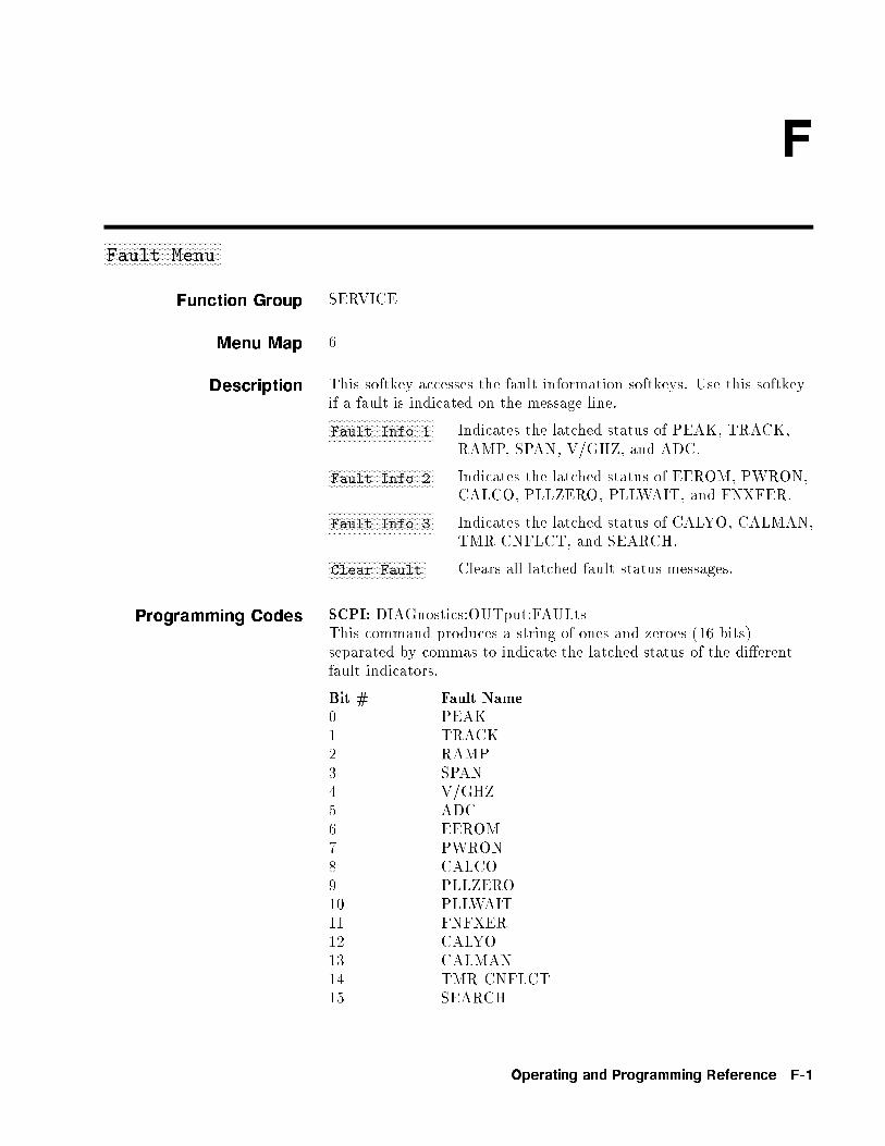
F
aaaaaaaaaaaaaaaaaaaaaaaaaaaaaaaaaaaaaaaaaaFault Menu
Function Group SERVICE
Menu Map 6
Description This softkey accesses the fault information softkeys. Use this softkeyif a fault is indicated on the message line.NNNNNNNNNNNNNNNNNNNNNNNNNNNNNNNNNNNNNNFault Info 1 Indicates the latched status of PEAK, TRACK,
RAMP, SPAN, V/GHZ, and ADC.NNNNNNNNNNNNNNNNNNNNNNNNNNNNNNNNNNNNNNFault Info 2 Indicates the latched status of EEROM, PWRON,
CALCO, PLLZERO, PLLWAIT, and FNXFER.NNNNNNNNNNNNNNNNNNNNNNNNNNNNNNNNNNNNNNFault Info 3 Indicates the latched status of CALYO, CALMAN,
TMR CNFLCT, and SEARCH.NNNNNNNNNNNNNNNNNNNNNNNNNNNNNNNNNNNClear Fault Clears all latched fault status messages.
Programming Codes SCPI: DIAGnostics:OUTput:FAULtsThis command produces a string of ones and zeroes (16 bits)separated by commas to indicate the latched status of the di�erentfault indicators.
Bit # Fault Name0 PEAK1 TRACK2 RAMP3 SPAN4 V/GHZ5 ADC6 EEROM7 PWRON8 CALCO9 PLLZERO10 PLLWAIT11 FNFXER12 CALYO13 CALMAN14 TMR CNFLCT15 SEARCH
Operating and Programming Reference F-1
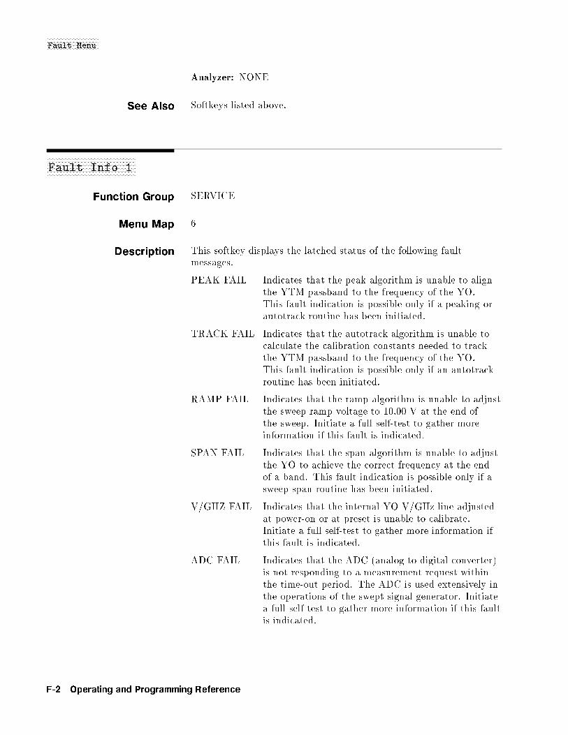
NNNNNNNNNNNNNNNNNNNNNNNNNNNNNFault Menu
Analyzer: NONE
See Also Softkeys listed above.
aaaaaaaaaaaaaaaaaaaaaaaaaaaaaaaaaaaaaaaaaaaaaaaaaaFault Info 1
Function Group SERVICE
Menu Map 6
Description This softkey displays the latched status of the following faultmessages.
PEAK FAIL Indicates that the peak algorithm is unable to alignthe YTM passband to the frequency of the YO.This fault indication is possible only if a peaking orautotrack routine has been initiated.
TRACK FAIL Indicates that the autotrack algorithm is unable tocalculate the calibration constants needed to trackthe YTM passband to the frequency of the YO.This fault indication is possible only if an autotrackroutine has been initiated.
RAMP FAIL Indicates that the ramp algorithm is unable to adjustthe sweep ramp voltage to 10.00 V at the end ofthe sweep. Initiate a full self-test to gather moreinformation if this fault is indicated.
SPAN FAIL Indicates that the span algorithm is unable to adjustthe YO to achieve the correct frequency at the endof a band. This fault indication is possible only if asweep span routine has been initiated.
V/GHZ FAIL Indicates that the internal YO V/GHz line adjustedat power-on or at preset is unable to calibrate.Initiate a full self-test to gather more information ifthis fault is indicated.
ADC FAIL Indicates that the ADC (analog-to-digital converter)is not responding to a measurement request withinthe time-out period. The ADC is used extensively inthe operations of the swept signal generator. Initiatea full self-test to gather more information if this faultis indicated.
F-2 Operating and Programming Reference
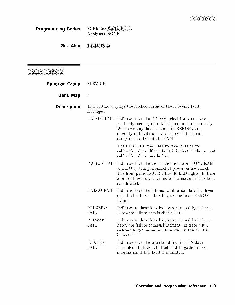
NNNNNNNNNNNNNNNNNNNNNNNNNNNNNNNNNNNFault Info 2
Programming Codes SCPI: SeeNNNNNNNNNNNNNNNNNNNNNNNNNNNNNNNNFault Menu .
Analyzer: NONE
See AlsoNNNNNNNNNNNNNNNNNNNNNNNNNNNNNNNNFault Menu
aaaaaaaaaaaaaaaaaaaaaaaaaaaaaaaaaaaaaaaaaaaaaaaaaaFault Info 2
Function Group SERVICE
Menu Map 6
Description This softkey displays the latched status of the following faultmessages.
EEROM FAIL Indicates that the EEROM (electrically erasableread only memory) has failed to store data properly.Whenever any data is stored in EEROM, theintegrity of the data is checked (read back andcompared to the data in RAM).
The EEROM is the main storage location forcalibration data. If this fault is indicated, the presentcalibration data may be lost.
PWRON FAIL Indicates that the test of the processor, ROM, RAMand I/O system performed at power-on has failed.The front panel INSTR CHECK LED lights. Initiatea full self-test to gather more information if this faultis indicated.
CALCO FAIL Indicates that the internal calibration data has beendefaulted either deliberately or due to an EEROMfailure.
PLLZEROFAIL
Indicates a phase lock loop error caused by either ahardware failure or misadjustment.
PLLWAITFAIL
Indicates a phase lock loop error caused by either ahardware failure or misadjustment. Initiate a fullself-test to gather more information if this fault isindicated.
FNXFERFAIL
Indicates that the transfer of fractional-N datahas failed. Initiate a full self-test to gather moreinformation if this fault is indicated.
Operating and Programming Reference F-3
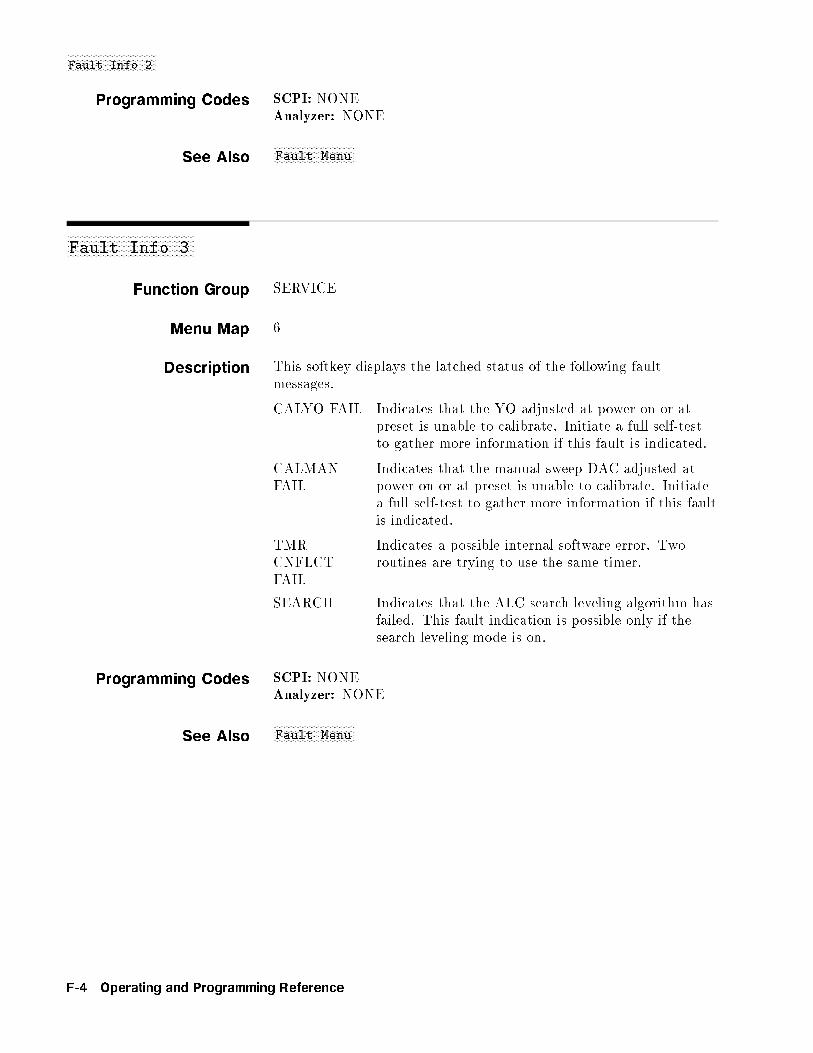
NNNNNNNNNNNNNNNNNNNNNNNNNNNNNNNNNNNFault Info 2
Programming Codes SCPI: NONEAnalyzer: NONE
See AlsoNNNNNNNNNNNNNNNNNNNNNNNNNNNNNNNNFault Menu
aaaaaaaaaaaaaaaaaaaaaaaaaaaaaaaaaaaaaaaaaaaaaaaaaaFault Info 3
Function Group SERVICE
Menu Map 6
Description This softkey displays the latched status of the following faultmessages.
CALYO FAIL Indicates that the YO adjusted at power-on or atpreset is unable to calibrate. Initiate a full self-testto gather more information if this fault is indicated.
CALMANFAIL
Indicates that the manual sweep DAC adjusted atpower-on or at preset is unable to calibrate. Initiatea full self-test to gather more information if this faultis indicated.
TMRCNFLCTFAIL
Indicates a possible internal software error. Tworoutines are trying to use the same timer.
SEARCH Indicates that the ALC search leveling algorithm hasfailed. This fault indication is possible only if thesearch leveling mode is on.
Programming Codes SCPI: NONEAnalyzer: NONE
See AlsoNNNNNNNNNNNNNNNNNNNNNNNNNNNNNNNNFault Menu
F-4 Operating and Programming Reference

NNNNNNNNNNNNNNNNNNNNNNNNNNNNNNNNNNNFltness Menu
aaaaaaaaaaaaaaaaaaaaaaaaaaaaaaaaaaaaaaaaaaaaaaaaaaFltness Menu
Function Group POWER
Menu Map 5
Description This softkey reveals the softkeys in the atness correction menu thatcontrol user-de�ned leveling parameters.NNNNNNNNNNNNNNNNNNNNNNNNNNNNNNNNNNNNNNNNNNNNAuto Fill Incr Automatically creates a frequency list with all
points separated by the speci�ed increment in agiven frequency range.NNNNNNNNNNNNNNNNNNNNNNNNNNNNNNNNNNNNNNNNNNNN
Auto Fill #Pts Automatically creates a frequency listcontaining the speci�ed number of points in agiven frequency range.NNNNNNNNNNNNNNNNNNNNNNNNNNNNNNNNNNNNNNNNNNNNNNN
Auto Fill Start Sets the start frequency of the atnesscorrection array that will load automaticallywhen either the number of points or theincrement size is speci�ed.NNNNNNNNNNNNNNNNNNNNNNNNNNNNNNNNNNNNNNNNNNNN
Auto Fill Stop Sets the stop frequency of the atness arraythat will load automatically when either thenumber of points or the increment size isspeci�ed.NNNNNNNNNNNNNNNNNNNNNNNNNNNNNNNNNNN
Clear Point Changes the power correction value for theindicated frequency point to the unde�ned state.NNNNNNNNNNNNNNNNNNNNNNNNNNNNN
Copy List Copies the frequency list, (seeNNNNNNNNNNNNNNNNNNNNNNNNNNNNNList Menu ),
into the frequency parameter of the atnesscorrection array.NNNNNNNNNNNNNNNNNNNNNNNNNNNNNNNNNNNNNNNNNNNNNNN
CorPair Disable Disables the frequency-correction pair array anduses the GPIB transferred 1601 point correctionset to apply correction information.NNNNNNNNNNNNNNNNNNNNNNNNNNNNNNNNNNN
Delete Menu Reveals the delete softkeys.
NNNNNNNNNNNNNNNNNNNNNNNNNNNNNNNNEnter Corr Enables the entry of a power correction value
for a frequency point.NNNNNNNNNNNNNNNNNNNNNNNNNNNNNNNNEnter Freq Enables the entry of a single frequency point
into the atness correction array.NNNNNNNNNNNNNNNNNNNNNNNNNNNNNNNNNNNFreq Follow Sets the swept signal generator to CW
frequency mode so that the correspondingcorrection values can be entered.NNNNNNNNNNNNNNNNNNNNNNNNNNNNNNNNNNNNNNNNN
Mtr Meas Menu Reveals the softkeys in the power meter measurecorrection menu.
Operating and Programming Reference F-5

NNNNNNNNNNNNNNNNNNNNNNNNNNNNNNNNNNNFltness Menu
The softkeys in this menu help front panel users enter and edit atness correction parameters. These editing softkeys are notaccessible over GPIB.
To load correction arrays over GPIB, the correction arrays must becreated in the controlling program and then downloaded to the sweptsignal generator. The corresponding SCPI array creation and controlcommands are given after the description of this feature.
The 8360 B-Series swept signal generator provide extremely atpower to a test port, for testing power sensitive devices such asampli�ers, mixers, diodes or detectors. The user atness correctionfeature of the swept signal generator compensates for attenuation andpower variations created by components between the source and thetest device.
User atness correction allows the digital correction of up to 801frequency points (1601 points via GPIB), in any frequency or sweepmode (i.e. start/stop, CW, power sweep etc.). Using a power meterto calibrate the measurement system as shown in Figure F-1, a tableof power level corrections is created for the frequencies where powerlevel variations or losses occur (see Figure F-2). These frequenciesmay be sequential linear steps or arbitrarily spaced. To allow for thecorrection of multiple test setups or frequency ranges, you may saveas many as eight di�erent measurement setups (including correctiontables) in the internal storage registers of the swept signal generator.
Figure F-1. Basic User Flatness Configuration Using an HP/Agilent 437B Power Meter
F-6 Operating and Programming Reference
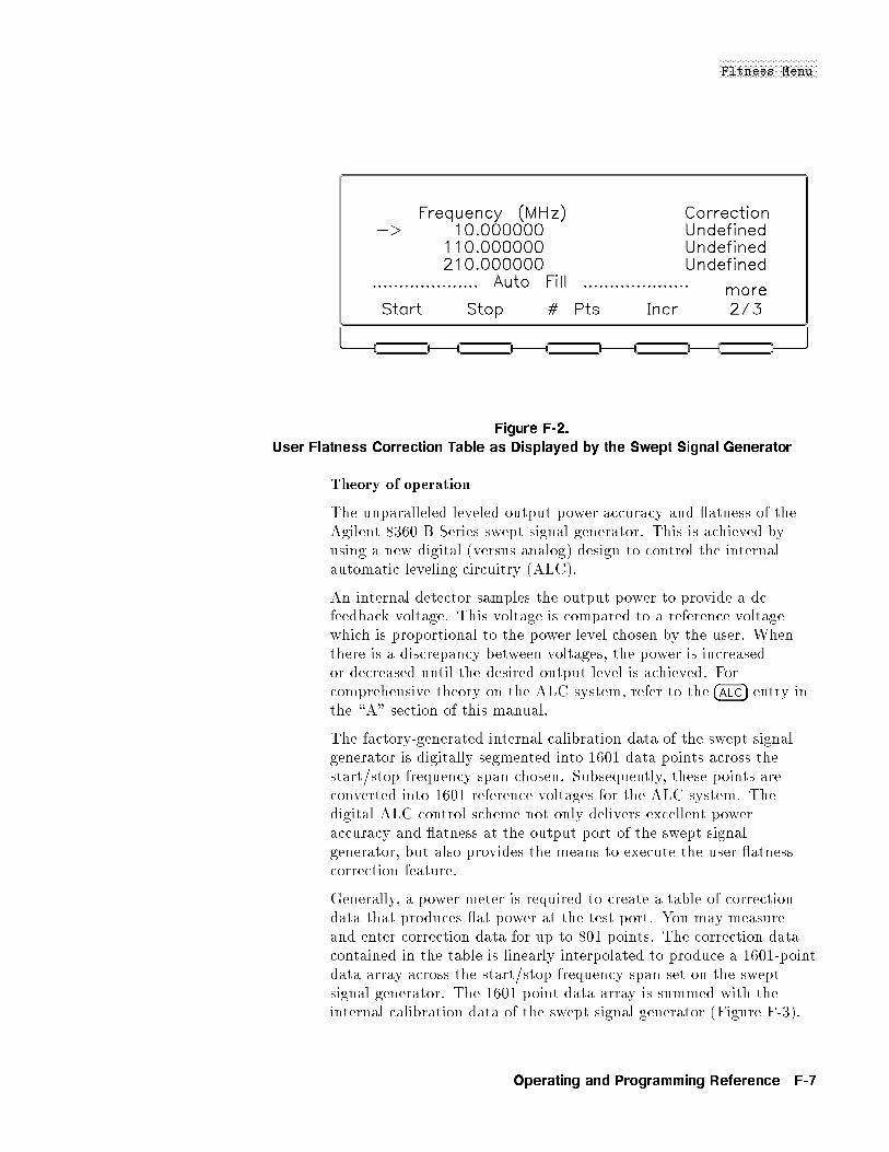
NNNNNNNNNNNNNNNNNNNNNNNNNNNNNNNNNNNFltness Menu
Figure F-2.
User Flatness Correction Table as Displayed by the Swept Signal Generator
Theory of operation
The unparalleled leveled output power accuracy and atness of theAgilent 8360 B-Series swept signal generator. This is achieved byusing a new digital (versus analog) design to control the internalautomatic leveling circuitry (ALC).
An internal detector samples the output power to provide a dcfeedback voltage. This voltage is compared to a reference voltagewhich is proportional to the power level chosen by the user. Whenthere is a discrepancy between voltages, the power is increasedor decreased until the desired output level is achieved. Forcomprehensive theory on the ALC system, refer to the �ALC� entry inthe \A" section of this manual.
The factory-generated internal calibration data of the swept signalgenerator is digitally segmented into 1601 data points across thestart/stop frequency span chosen. Subsequently, these points areconverted into 1601 reference voltages for the ALC system. Thedigital ALC control scheme not only delivers excellent poweraccuracy and atness at the output port of the swept signalgenerator, but also provides the means to execute the user atnesscorrection feature.
Generally, a power meter is required to create a table of correctiondata that produces at power at the test port. You may measureand enter correction data for up to 801 points. The correction datacontained in the table is linearly interpolated to produce a 1601-pointdata array across the start/stop frequency span set on the sweptsignal generator. The 1601-point data array is summed with theinternal calibration data of the swept signal generator (Figure F-3).
Operating and Programming Reference F-7

NNNNNNNNNNNNNNNNNNNNNNNNNNNNNNNNNNNFltness Menu
When user atness correction is enabled, the sum of the two arraysproduces the 1601 reference voltages for the ALC system.
Figure F-3. The Sources of ALC Calibration Correction Data
If the correction frequency span is only a subset of the start/stopfrequency span set on the source, no corrections are applied to theportion of the sweep that is outside the correction frequency span.The following example illustrates how the data is distributed withinthe user atness correction array.
Assume that the swept signal generator is set to sweep from 2 to18 GHz, but you only enter user atness correction data from14 to 18 GHz. Linear interpolation occurs between the correctionentries to provide the 401 points required for the 14 to 18 GHzportion of the array. No corrections are applied to the 2 to13.99 GHz portion of the array. Refer to Figure F-4.
Figure F-4.
Array Configuration when the Correction Data Frequency Span
is a Subset of the Swept Signal Generator Frequency Span
Number of points interpolated between correction entries iscalculated as follows:�
freq: span between correction entries
stop frequency � start frequency
�1600� 1 = Number of pts
F-8 Operating and Programming Reference

NNNNNNNNNNNNNNNNNNNNNNNNNNNNNNNNNNNFltness Menu
When correction frequencies are arbitrarily spaced, the number ofinterpolated points varies.
When utilizing the user atness correction feature, do not exceedthe swept signal generator ALC operating range. Exceeding theALC range causes the output power to become unleveled andeliminates the bene�ts of user atness correction. The ALC rangecan be determined by subtracting the minimum output power(�20 dBm) from the maximum speci�ed power. When the optionalstep attenuator is ordered on a swept signal generator, at times itmay be necessary to uncouple the attenuator to obtain the full ALCrange. This can be accomplished by selecting POWER [MENU][Uncoupl Atten]. For example, an Agilent 83620B has an ALC rangeof �30 dB (�+10 to �20 dBm).
When user atness correction is enabled, the maximum settable testport power is equivalent to the maximum available leveled powerminus the maximum path loss (Po max � Ppath loss). For example,if an 83620B has a maximum path loss of 15 dB due to systemcomponents between the source output and the test port, the testport power should be set to �5 dBm. When user atness correctionis enabled, this provides the maximum available power to the deviceunder test (DUT).
Programming Codes SCPI:
CORRection:FLATness f<num>[freq su�x],<num>[DB]g2*801
The portion of the above command contained in f g can beentered from one to 801 times. This command creates thefrequency-correction pair array similar to the front panel array.The correction entered is at the associated frequency andfrequencies in between are determined by linear interpolation.
CORRection:FLATness?
This command queries the atness array created with CORR:FLAT.
CORRection:ARRay[i] f<num>[DB]g1601*1601
The portion of the above command contained in fg mustbe entered 1601 times. This array must contain 1601 evenlyspaced correction values. This command creates the 1601-pointcorrection set that has no equivalent front panel entry. If thiscommand is used to enter atness correction information theCORRection:SOURce command (described below) will be set toarray. There is an array for the foreground state (i=0) and for thebackground state (i=1). If [i] is not speci�ed, the default is theforeground state (i=0).
CORRection:ARRay[i]?
This command queries the entire 1601-point correction set.
CORRection:SOURce[i] ARRayjFLATness
Operating and Programming Reference F-9
NNNNNNNNNNNNNNNNNNNNNNNNNNNNNNNNNNNFltness Menu
When the above command is set to atness CORR:SOUR FLAT, thearray chosen is the frequency-correction pair array. When thecommand is set to array CORR:SOUR ARR, the array chosen is the1601 point correction set.
CORRection:SOURce[i]?
Queries the source of correction.
CORRection[:STATe] ONjOFFj1j0
Sets the switch on the user atness correction feature. This is thesame as pressing �FLTNESS ON/OFF� on the front panel.
CORRection:STATe?
Queries the condition of the internal switch.
CORRection:FLATness:POINts? [MAXimumjMINimum]
The above command returns information on how manyfrequency-correction pairs were entered using the CORR:FLATcommand.
Analyzer: NONE
See Also �ALC�, �FLTNESS ON/OFF�,NNNNNNNNNNNNNNNNNNNNNNNNNNNNNList Menu
\Optimizing Swept Signal Generator Performance" in Chapter 1\Programming Typical Measurements" in Chapter 1
�FLTNESS ON/OFF�
Function Group POWER
Menu Map 5
Description This hardkey applies atness correction to the swept signal generatorRF output. If no array has been created, pressing this key applies0 dB of atness correction at all points. The yellow LED above thehardkey lights when user atness correction is on.
Programming Codes SCPI: CORRection[:STATe] ONjOFFj1j0Analyzer: NONE
See Also �ALC�,NNNNNNNNNNNNNNNNNNNNNNNNNNNNNNNNNNNNNNFltness Menu
\Optimizing Swept Signal Generator Performance" in Chapter 1
F-10 Operating and Programming Reference
NNNNNNNNNNNNNNNNNNNNNNNNNNNNNNNNNNNNNNNNFM Coupling DC
aaaaaaaaaaaaaaaaaaaaaaaaaaaaaaaaaaaaaaaaaaaaaaaaaaaaaaaaaaaaaaaaaaaaaaaaaFM Coupling 100kHz
Function Group �MOD�
Menu Map 4
Description This softkey (Option 002 only) lets you set the FM input to beAC-coupled. If you choose AC-coupled FM, you will be modulating aphase locked carrier. This is the speci�ed synthesized operation. Youmust modulate at a 100 kHz rate or greater. If not, the frequencychanges caused by the modulation are inside the phase locked loopbandwidth and the output will not be linear FM. For modulationfrequencies below 100 kHz, choose DC-coupled FM.
An asterisk next to the key label indicates that AC FM coupling isselected. This selection is the factory preset default.
For swept signal generators without Option 002, seeNNNNNNNNNNNNNNNNNNNNNNNNNNNNNNNNNNNNNNNNNNNNNNNNNNNNNFM On/Off 100 kHz .
Programming Codes SCPI: FM:FILTer:HPASs <num>[freq su�x]jMAXimumjMINimum<num> sets the AC bandwidth to 100 kHz for any value > 1 kHzand sets the AC bandwidth to 20 Hz for any value � 1 kHz.Analyzer: NONE
See Also �MOD�, also see \FM" and \Modulation".
aaaaaaaaaaaaaaaaaaaaaaaaaaaaaaaaaaaaaaaaaaaaaaaaaaaaaaaaaFM Coupling DC
Function Group �MOD�
Menu Map 4
Description This softkey (Option 002 only) lets you set the FM input to beDC-coupled. Use DC coupling for modulation rates below 100 kHz.In this mode, the phase-locked loop is de-activated. This means thatthe swept signal generator is operating as an open loop sweeper. Theswept signal generator will not be phase locked, and therefore, beaware that the phase noise and CW frequency accuracy speci�cationsdo not apply.
An asterisk next to the key label indicates that DC FM coupling isselected. The factory preset default is AC coupling.
For swept signal generators without Option 002, seeNNNNNNNNNNNNNNNNNNNNNNNNNNNNNNNNNNNNNNFM On/Off DC .
Operating and Programming Reference F-11

NNNNNNNNNNNNNNNNNNNNNNNNNNNNNNNNNNNNNNNNFM Coupling DC
Programming Codes SCPI: FM:FILTer:HPASs <num>[freq su�x]jMAXimumjMINimumAnalyzer: NONE
See Also �MOD�, also see \FM" and \Modulation".
aaaaaaaaaaaaaaaaaaaaaaaaaaaaaaFM Menu
Function Group �MOD�
Menu Map 4
Description This softkey (Option 002 only) accesses the frequency modulationsoftkeys. These softkeys engage external and internal frequencymodulation. They allow you to de�ne the coupling, waveform, rate,and deviation of the internal FM.NNNNNNNNNNNNNNNNNNNNNNNNNNNNNNNNNNNNNNNNNFM On/Off Ext Toggles on and o� the frequency
modulation mode for an external FMsource.NNNNNNNNNNNNNNNNNNNNNNNNNNNNNNNNNNNNNNNNN
FM On/Off Int Toggles on and o� the frequencymodulation mode using the internalFM generator.NNNNNNNNNNNNNNNNNNNNNNNNNNNNNNNNNNNNNNNNNNNNNNNNNN
Internal FM Rate Sets the rate of the internal frequencymodulation.NNNNNNNNNNNNNNNNNNNNNNNNNNNNNNNNNNNNNNNNNNNNNNNNNNNNNNNNNNNNNNNNN
Internal FM Deviation Sets the deviation of the internalfrequency modulation.NNNNNNNNNNNNNNNNNNNNNNNNNNNNNNNNNNNNNNNNNNNNNNNNNNNNNNNN
FM Coupling 100kHz Sets AC coupling for modulation ratesof 100 kHz or greater. The RF signalis phase locked.NNNNNNNNNNNNNNNNNNNNNNNNNNNNNNNNNNNNNNNNNNNN
FM Coupling DC Sets DC coupling for modulationrates of less than 100 kHz. The phaselocked loop is open.NNNNNNNNNNNNNNNNNNNNNNNNNNNNNNNNNNNNNNNNN
Waveform Menu Displays the waveforms for internalfrequency modulation.
Programming Codes SCPI: NONE, see the individual softkeys listed.Analyzer: NONE
See Also �MOD�, also see \FM" and \Modulation".
F-12 Operating and Programming Reference

NNNNNNNNNNNNNNNNNNNNNNNNNNNNNNNNNNNFM On/Off DC
aaaaaaaaaaaaaaaaaaaaaaaaaaaaaaaaaaaaaaaaaaaaaaaaaaFM On/Off AC
Function Group MODULATION
Menu Map 4
Description This softkey lets you select AC coupled frequency modulation(FM), and makes FM deviation frequency the active function.FM sensitivity is selectable. Use the rotary knob, up/down, ornumeric entry keys to choose, 100 kHz, 1.00 MHz/V or 10.0 MHz/V.Frequency deviation is dependent on the magnitude of the inputsignal. An asterisk next to the key label indicates that this feature isactive.
Programming Codes SCPI:
FM:SENSitivity <num>[freq/V su�x]jMAXimumjMINimumFM:COUPling ACFM:STATe ONjOFFj1j0
Analyzer:
FM1 function on, followed by either 100 kHz, 1MHz, or 10 MHzFM0 function o�
See Also �MOD�, CONNECTORS
aaaaaaaaaaaaaaaaaaaaaaaaaaaaaaaaaaaaaaaaaaaaaaaaaaFM On/Off DC
Function Group MODULATION
Menu Map 4
Description This softkey lets you select DC coupled frequency modulation(FM) and makes FM deviation frequency the active function.FM sensitivity is selectable. Use the rotary knob, up/down, ornumeric entry keys to choose, 100 kHz, 1.00 MHz/V or 10.0 MHz/V.Frequency deviation is dependent on the magnitude of the inputsignal. When DC FM is chosen the swept signal generator displaysDC FM on the message line. An asterisk next to the key label indicatesthat this feature is active.
Operating and Programming Reference F-13

NNNNNNNNNNNNNNNNNNNNNNNNNNNNNNNNNNNFM On/Off DC
Programming Codes SCPI:
FM:SENSitivity <num>[freq/V su�x][MAXimumjMINimumFM:COUPling ACFM:STATe ONjOFFj1j0
Analyzer: NONE
See Also �MOD�, CONNECTORS
aaaaaaaaaaaaaaaaaaaaaaaaaaaaaaaaaaaaaaaaaaaaaaaaaaaaaaFM On/Off Ext
Function Group �MOD�
Menu Map 4
Description This softkey (Option 002 only) activates the frequency modulationmode for an external source. The FM source is connected to the FMmodulation connector. The FM sensitivity function is active. It isfactory preset to 10 MHz/V. Use the numeric entry keys, arrow keys,or rotary knob to change the sensitivity to 100 kHz/V or 1 MHz/V.
When external FM is in e�ect, the RF output is frequency modulatedwith a rate and depth set by the external source. The FM couplingis controlled by the following softkeys:
NNNNNNNNNNNNNNNNNNNNNNNNNNNNNNNNNNNNNNNNNNNNNNNNNNNNNNNNFM Coupling 100kHzNNNNNNNNNNNNNNNNNNNNNNNNNNNNNNNNNNNNNNNNNNNN
FM Coupling DC . The FM coupling defaults to 100 kHz. This is ACcoupling for FM rates of 100 kHz or greater. For modulation ratesbelow 100 kHz, choose DC-coupled FM.
An asterisk next to the key label indicates that external FM is activeand FM is displayed on the message line.
For swept signal generators without Option 002, seeNNNNNNNNNNNNNNNNNNNNNNNNNNNNNNNNNNNNNNFM On/Off AC
andNNNNNNNNNNNNNNNNNNNNNNNNNNNNNNNNNNNNNNFM On/Off DC .
Programming Codes SCPI:
FM:SOURce EXTernalFM:SENSitivity <num>[freq su�x/V]jMAXimumjMINimumFM:STATe ONjOFF
Analyzer: FM1 function on, FM0 function o�
See Also �MOD�, also see \FM" and \Modulation".
F-14 Operating and Programming Reference
NNNNNNNNNNNNNNNNNNNNNNNNNNNNNNNNNNNNNFM On/Off Int
aaaaaaaaaaaaaaaaaaaaaaaaaaaaaaaaaaaaaaaaaaaaaaaaaaaaaaFM On/Off Int
Function Group �MOD�
Menu Map 4
Description This softkey (Option 002 only) activates the internal frequencymodulation mode. No external source is needed.
When internal FM is in e�ect, the parameters are controlled by thefollowing softkeys:
NNNNNNNNNNNNNNNNNNNNNNNNNNNNNNNNNNNNNNNNNNNNNNNNNNInternal FM Rate
NNNNNNNNNNNNNNNNNNNNNNNNNNNNNNNNNNNNNNNNNNNNNNNNNNNNNNNNNNNNNNNNNInternal FM DeviationNNNNNNNNNNNNNNNNNNNNNNNNNNNNNNNNNNNNNNNNNNNNNNNNNNNNNNNN
FM Coupling 100kHzNNNNNNNNNNNNNNNNNNNNNNNNNNNNNNNNNNNNNNNNNNNNFM Coupling DC
NNNNNNNNNNNNNNNNNNNNNNNNNNNNNNNNNNNNNNNNNWaveform Menu . The
swept signal generator is factory preset to a 1 MHz rate, 1 MHzdeviation, and sine wave parameters.
An asterisk next to the key label indicates that internal FM is activeand FM is displayed on the message line.
Programming Codes SCPI:
FM:SOURce INTernalFM:STATe ONjOFF
Analyzer: NONE
See Also �MOD�, also see \FM" and \Modulation".
Operating and Programming Reference F-15
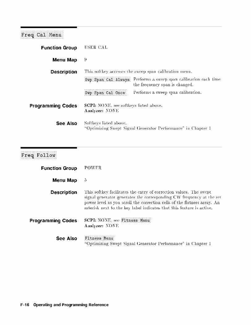
aaaaaaaaaaaaaaaaaaaaaaaaaaaaaaaaaaaaaaaaaaaaaaaaaaaaaaFreq Cal Menu
Function Group USER CAL
Menu Map 9
Description This softkey accesses the sweep span calibration menu.NNNNNNNNNNNNNNNNNNNNNNNNNNNNNNNNNNNNNNNNNNNNNNNNNNNNNNNNNNNSwp Span Cal Always Performs a sweep span calibration each time
the frequency span is changed.NNNNNNNNNNNNNNNNNNNNNNNNNNNNNNNNNNNNNNNNNNNNNNNNNNNNNSwp Span Cal Once Performs a sweep span calibration.
Programming Codes SCPI: NONE, see softkeys listed above.Analyzer: NONE
See Also Softkeys listed above.\Optimizing Swept Signal Generator Performance" in Chapter 1
aaaaaaaaaaaaaaaaaaaaaaaaaaaaaaaaaaaaaaaaaaaaaaFreq Follow
Function Group POWER
Menu Map 5
Description This softkey facilitates the entry of correction values. The sweptsignal generator generates the corresponding CW frequency at the setpower level as you scroll the correction cells of the atness array. Anasterisk next to the key label indicates that this feature is active.
Programming Codes SCPI: NONE, seeNNNNNNNNNNNNNNNNNNNNNNNNNNNNNNNNNNNNNNFltness Menu
Analyzer: NONE
See AlsoNNNNNNNNNNNNNNNNNNNNNNNNNNNNNNNNNNNNNNFltness Menu
\Optimizing Swept Signal Generator Performance" in Chapter 1
F-16 Operating and Programming Reference

FREQUENCY �MENU�
FREQUENCY �MENU�
Function Group FREQUENCY
Menu Map 2
Description This hardkey allows access to the frequency functions listed below.NNNNNNNNNNNNNNNNNNNNNNNNNNNNNNNNNNNNNNNNNCW/CF Coupled When this feature is on, the center
frequency and the CW frequency iskept equal. Changing either the centerfrequency or the CW frequency causes theother to change to the same value. Anasterisk next to the key label indicates thatthis feature is active.NNNNNNNNNNNNNNNNNNNNNNNNNNNNN
Freq Mult Sets the frequency multiplier value andapplies it to all frequency parameters.NNNNNNNNNNNNNNNNNNNNNNNNNNNNNNNNNNN
Freq Offset Sets the frequency o�set value and appliesit to all frequency parameters.NNNNNNNNNNNNNNNNNNNNNNNNNNNNN
List Menu Displays the frequency list create/editsoftkeys.NNNNNNNNNNNNNNNNNNNNNNNNNNNNNNNNNNNNNNNNN
Step Swp Menu Reveals the stepped frequency sweep editsoftkeys.NNNNNNNNNNNNNNNNNNNNNNNNNNNNNNNNNNNNNNNNNNNNNNN
Up/Down Size CW Sets the frequency step size in the CWfrequency mode.NNNNNNNNNNNNNNNNNNNNNNNNNNNNNNNNNNNNNNNNNNNNNNNNNNNNNNNN
Up/Down Size Swept Sets the frequency step size in the sweptfrequency mode.NNNNNNNNNNNNNN
Zoom Places the swept signal generator in theCF/�F sweep mode, where the rotaryknob and numeric entry keys control CF,and the up/down arrow keys control �F.
See Also Softkeys listed above.\Optimizing Swept Signal Generator Performance" in Chapter 1
Operating and Programming Reference F-17

aaaaaaaaaaaaaaaaaaaaaaaaaaaaaaaaaaaaaaFreq Mult
Function Group FREQUENCY
Menu Map 2
Description This softkey lets you set a frequency multiplier value and applies it toall frequency parameters. Any integer value between and including�36 is accepted. Changing the multiplier value changes the display,it does not a�ect the output of the swept signal generator.
For example:
1. Set the start frequency to 4 GHz.
2. Set the stop frequency to 10 GHz.
3. Set the frequency multiplier to 5.
Note that the display indicates start=20 GHz, stop=50 GHz andasterisks appear next to the frequency data.
4. Now set the stop frequency to 30 GHz. The swept signal generatorfrequency is 6 GHz, or 30 GHz � 5.
Frequency multiplier and o�set are related as shown by the followingequation:
Entered value or Displayed Frequency = (Frequency Generated � Multiplier) + O�set value
The factory preset value is 1. An asterisk next to the key labelindicates that this feature is active.
Programming Codes SCPI:
FREQuency:MULTiplier <num>jMAXimumjMinimumFREQuency:MULTiplier:STATe ONjOFFj1j0
<num> will be rounded to the nearest integer.Analyzer: SHFA <n>
See Also FREQUENCY �MENU�,NNNNNNNNNNNNNNNNNNNNNNNNNNNNNNNNNNNFreq Offset
F-18 Operating and Programming Reference

NNNNNNNNNNNNNNNNNNNNNNNNNNNNNNNNFreq Offset
aaaaaaaaaaaaaaaaaaaaaaaaaaaaaaaaaaaaaaaaaaaaaaFreq Offset
Function Group FREQUENCY
Menu Map 2
Description This softkey lets you set a frequency o�set value and applies it toall frequency parameters. The frequency o�set ranges between andincluding �110.0 GHz. Changing the frequency o�set value changesthe display but does not a�ect the output frequency. Frequencymultiplier and o�set are related as shown by the following equation:
Entered value or Displayed Frequency = (Frequency Generated � Multiplier) + O�set value
The factory preset value is 0 Hz. An asterisk next to the key labelindicates that this feature is active.
Programming Codes SCPI:
FREQuency:OFFSet <num>jMAXimumjMINimumFREQuency:OFFSet:STATe ONjOFFj1j0
Analyzer: SHFB <n>[HzjKzjMzjGzj]
See Also FREQUENCY �MENU�,NNNNNNNNNNNNNNNNNNNNNNNNNNNNNFreq Mult
Operating and Programming Reference F-19

aaaaaaaaaaaaaaaaaaaaaaaaaaaaaaaaaaaaaaaaaaaaaaFullUsr Cal
Function Group USER CAL
Menu Map 9
Description This softkey initiates a full swept signal generator user calibration.The calibration performed is instrument state dependent. Forexample, if the swept signal generator is in ramp sweep mode, asweep span calibration and an auto track is done. If the swept signalgenerator has amplitude modulation active on a CW signal, then RFpeaking and an AM bandwidth calibration is performed.
Programming Codes SCPI:See the individual types of calibration.Analyzer: NONE
See AlsoNNNNNNNNNNNNNNNNNNNNNNNNNNNNNNNNNNNNNNNNNNNNNNNNNNAM BW Cal Always ,
NNNNNNNNNNNNNNNNNNNNNNNNNNNNNNNNNNNNNNNNNNNNAM BW Cal Once ,
NNNNNNNNNNNNNNNNNNNNNNNNNNNNNNNNAuto Track ,NNNNNNNNNNNNNNNNNNNNNNNNNNNNNNNNNNNNNNNNNNNN
Peak RF Always ,NNNNNNNNNNNNNNNNNNNNNNNNNNNNNNNNNNNNNNPeak RF Once ,
NNNNNNNNNNNNNNNNNNNNNNNNNNNNNNNNNNNNNNNNNNNNNNNNNNNNNNNNNNNSwp Span Cal Always ,NNNNNNNNNNNNNNNNNNNNNNNNNNNNNNNNNNNNNNNNNNNNNNNNNNNNN
Swp Span Cal Once
F-20 Operating and Programming Reference
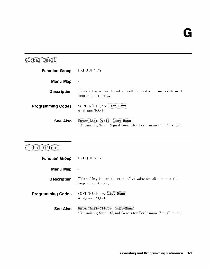
G
aaaaaaaaaaaaaaaaaaaaaaaaaaaaaaaaaaaaaaaaaaaaaaaaaaGlobal Dwell
Function Group FREQUENCY
Menu Map 2
Description This softkey is used to set a dwell time value for all points in thefrequency list array.
Programming Codes SCPI: NONE, seeNNNNNNNNNNNNNNNNNNNNNNNNNNNNNList Menu
Analyzer:NONE
See AlsoNNNNNNNNNNNNNNNNNNNNNNNNNNNNNNNNNNNNNNNNNNNNNNNNNNEnter List Dwell ,
NNNNNNNNNNNNNNNNNNNNNNNNNNNNNList Menu
\Optimizing Swept Signal Generator Performance" in Chapter 1
aaaaaaaaaaaaaaaaaaaaaaaaaaaaaaaaaaaaaaaaaaaaaaaaaaaaaaGlobal Offset
Function Group FREQUENCY
Menu Map 2
Description This softkey is used to set an o�set value for all points in thefrequency list array.
Programming Codes SCPI:NONE, seeNNNNNNNNNNNNNNNNNNNNNNNNNNNNNList Menu
Analyzer: NONE
See AlsoNNNNNNNNNNNNNNNNNNNNNNNNNNNNNNNNNNNNNNNNNNNNNNNNNNNNNEnter List Offset ,
NNNNNNNNNNNNNNNNNNNNNNNNNNNNNList Menu
\Optimizing Swept Signal Generator Performance" in Chapter 1
Operating and Programming Reference G-1
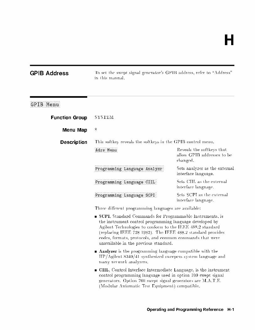
H
GPIB Address To set the swept signal generator's GPIB address, refer to \Address"in this manual.
aaaaaaaaaaaaaaaaaaaaaaaaaaaaaaaaaaaaaaGPIB Menu
Function Group SYSTEM
Menu Map 8
Description This softkey reveals the softkeys in the GPIB control menu.NNNNNNNNNNNNNNNNNNNNNNNNNNNNNAdrs Menu Reveals the softkeys that
allow GPIB addresses to bechanged.NNNNNNNNNNNNNNNNNNNNNNNNNNNNNNNNNNNNNNNNNNNNNNNNNNNNNNNNNNNNNNNNNNNNNNNNNNNNNNNNNNNNNN
Programming Language Analyzr Sets analyzer as the externalinterface language.NNNNNNNNNNNNNNNNNNNNNNNNNNNNNNNNNNNNNNNNNNNNNNNNNNNNNNNNNNNNNNNNNNNNNNNNNNNNN
Programming Language CIIL Sets CIIL as the externalinterface language.NNNNNNNNNNNNNNNNNNNNNNNNNNNNNNNNNNNNNNNNNNNNNNNNNNNNNNNNNNNNNNNNNNNNNNNNNNNNN
Programming Language SCPI Sets SCPI as the externalinterface language.
Three di�erent programming languages are available:
SCPI, Standard Commands for Programmable Instruments, isthe instrument control programming language developed byAgilent Technologies to conform to the IEEE 488.2 standard(replacing IEEE 728-1982). The IEEE 488.2 standard providescodes, formats, protocols, and common commands that wereunavailable in the previous standard.
Analyzer is the programming language compatible with theHP/Agilent 8340/41 synthesized sweepers system language andmany network analyzers.
CIIL, Control Interface Intermediate Language, is the instrumentcontrol programming language used in option 700 swept signalgenerators. Option 700 swept signal generators are M.A.T.E.(Modular Automatic Test Equipment) compatible.
Operating and Programming Reference H-1

NNNNNNNNNNNNNNNNNNNNNNNNNNGPIB Menu
See Also CONNECTORS, GPIB\Getting Started Programming" in Chapter 1
H-2 Operating and Programming Reference
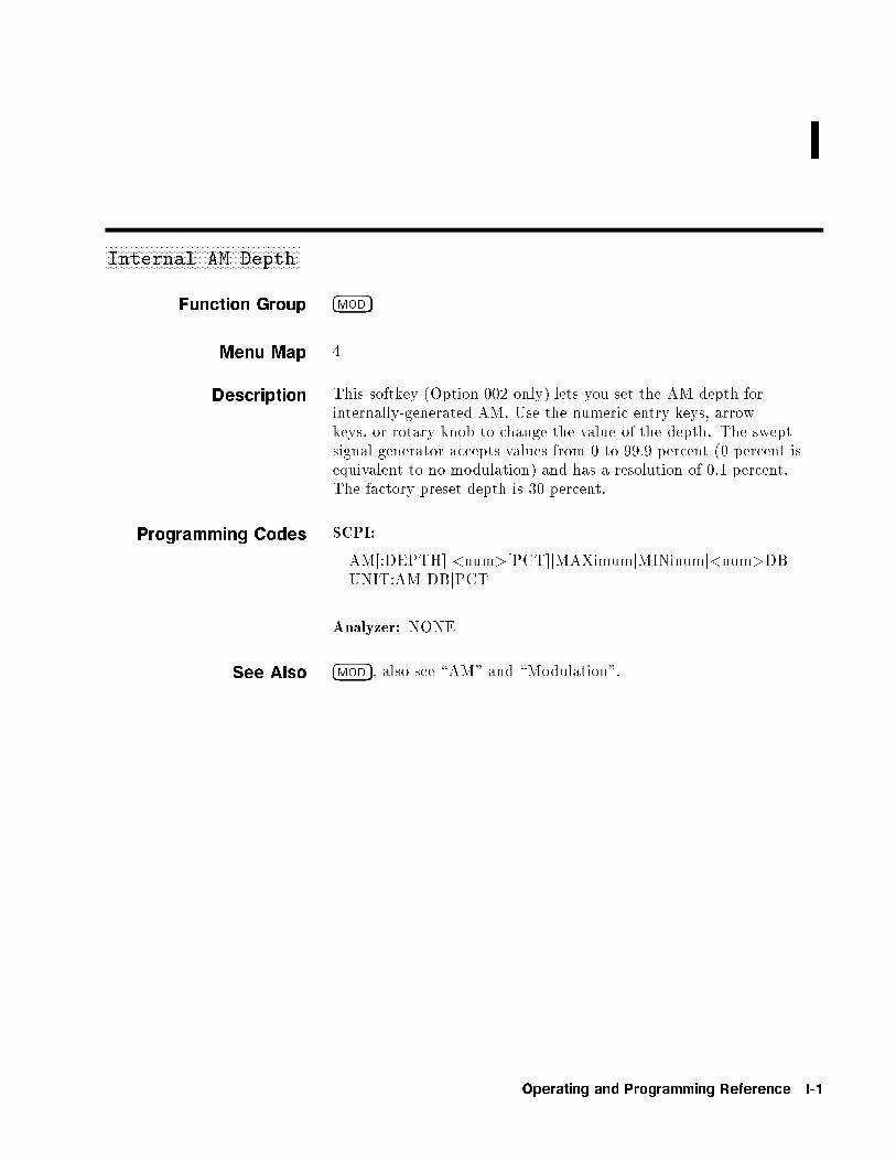
I
aaaaaaaaaaaaaaaaaaaaaaaaaaaaaaaaaaaaaaaaaaaaaaaaaaaaaaaaaaaaaaaaaaaaaInternal AM Depth
Function Group �MOD�
Menu Map 4
Description This softkey (Option 002 only) lets you set the AM depth forinternally-generated AM. Use the numeric entry keys, arrowkeys, or rotary knob to change the value of the depth. The sweptsignal generator accepts values from 0 to 99.9 percent (0 percent isequivalent to no modulation) and has a resolution of 0.1 percent.The factory preset depth is 30 percent.
Programming Codes SCPI:
AM[:DEPTH] <num>[PCT]jMAXimumjMINinumj<num>DBUNIT:AM DBjPCT
Analyzer: NONE
See Also �MOD�, also see \AM" and \Modulation".
Operating and Programming Reference I-1
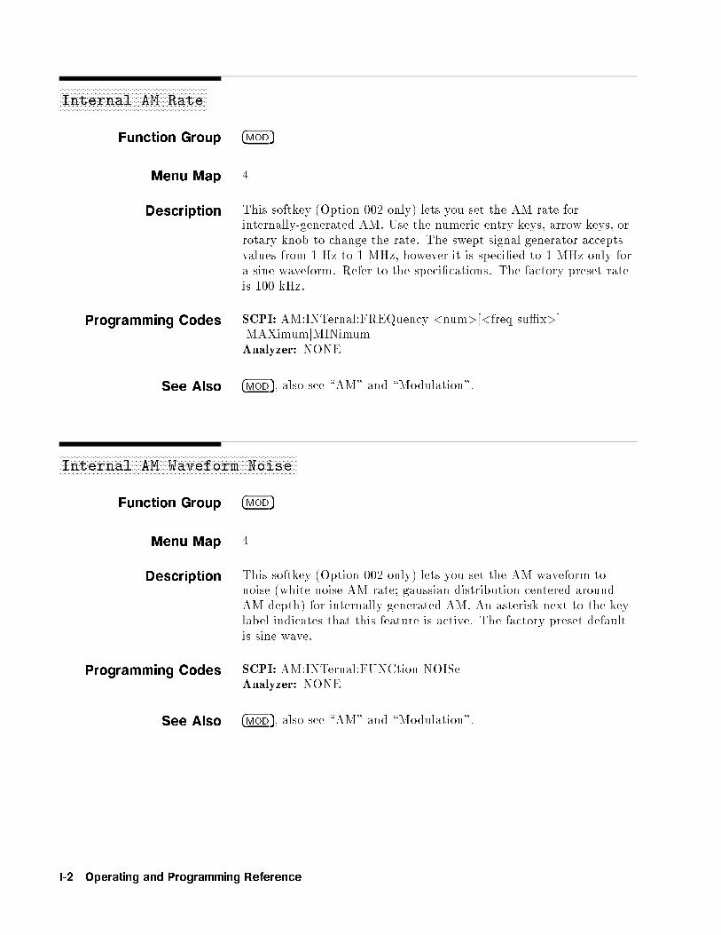
aaaaaaaaaaaaaaaaaaaaaaaaaaaaaaaaaaaaaaaaaaaaaaaaaaaaaaaaaaaaaaaaaInternal AM Rate
Function Group �MOD�
Menu Map 4
Description This softkey (Option 002 only) lets you set the AM rate forinternally-generated AM. Use the numeric entry keys, arrow keys, orrotary knob to change the rate. The swept signal generator acceptsvalues from 1 Hz to 1 MHz, however it is speci�ed to 1 MHz only fora sine waveform. Refer to the speci�cations. The factory preset rateis 100 kHz.
Programming Codes SCPI: AM:INTernal:FREQuency <num>[<freq su�x>]jMAXimumjMINimumAnalyzer: NONE
See Also �MOD�, also see \AM" and \Modulation".
aaaaaaaaaaaaaaaaaaaaaaaaaaaaaaaaaaaaaaaaaaaaaaaaaaaaaaaaaaaaaaaaaaaaaaaaaaaaaaaaaaaaaaaaaaaaaaaaaaaaaaaaaInternal AM Waveform Noise
Function Group �MOD�
Menu Map 4
Description This softkey (Option 002 only) lets you set the AM waveform tonoise (white noise AM rate; gaussian distribution centered aroundAM depth) for internally-generated AM. An asterisk next to the keylabel indicates that this feature is active. The factory preset defaultis sine wave.
Programming Codes SCPI: AM:INTernal:FUNCtion NOISeAnalyzer: NONE
See Also �MOD�, also see \AM" and \Modulation".
I-2 Operating and Programming Reference

NNNNNNNNNNNNNNNNNNNNNNNNNNNNNNNNNNNNNNNNNNNNNNNNNNNNNNNNNNNNNNNNNNNNNNInternal AM Waveform Sine
aaaaaaaaaaaaaaaaaaaaaaaaaaaaaaaaaaaaaaaaaaaaaaaaaaaaaaaaaaaaaaaaaaaaaaaaaaaaaaaaaaaaaaaaaaaaaaaaaaaaaInternal AM Waveform Ramp
Function Group �MOD�
Menu Map 4
Description This softkey (Option 002 only) lets you set the AM waveform toramp for internally-generated AM. An asterisk next to the key labelindicates that this feature is active. The factory preset default is sinewave.
Programming Codes SCPI: AM:INTernal:FUNCtion RAMPAnalyzer: NONE
See Also �MOD�, also see \AM" and \Modulation".
aaaaaaaaaaaaaaaaaaaaaaaaaaaaaaaaaaaaaaaaaaaaaaaaaaaaaaaaaaaaaaaaaaaaaaaaaaaaaaaaaaaaaaaaaaaaaaaaaaaaaInternal AM Waveform Sine
Function Group �MOD�
Menu Map 4
Description This softkey (Option 002 only) lets you set the AM waveform to sinewave for internally-generated AM. An asterisk next to the key labelindicates that this feature is active. Sine wave is the factory presetwaveform.
Programming Codes SCPI: AM:INTernal:FUNCtion SINusoidAnalyzer: NONE
See Also �MOD�, also see \AM" and \Modulation".
Operating and Programming Reference I-3
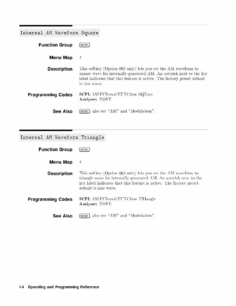
aaaaaaaaaaaaaaaaaaaaaaaaaaaaaaaaaaaaaaaaaaaaaaaaaaaaaaaaaaaaaaaaaaaaaaaaaaaaaaaaaaaaaaaaaaaaaaaaaaaaaaaaaaaaInternal AM Waveform Square
Function Group �MOD�
Menu Map 4
Description This softkey (Option 002 only) lets you set the AM waveform tosquare wave for internally-generated AM. An asterisk next to the keylabel indicates that this feature is active. The factory preset defaultis sine wave.
Programming Codes SCPI: AM:INTernal:FUNCtion SQUareAnalyzer: NONE
See Also �MOD�, also see \AM" and \Modulation".
aaaaaaaaaaaaaaaaaaaaaaaaaaaaaaaaaaaaaaaaaaaaaaaaaaaaaaaaaaaaaaaaaaaaaaaaaaaaaaaaaaaaaaaaaaaaaaaaaaaaaaaaaaaaaaaaaaaaInternal AM Waveform Triangle
Function Group �MOD�
Menu Map 4
Description This softkey (Option 002 only) lets you set the AM waveform totriangle wave for internally-generated AM. An asterisk next to thekey label indicates that this feature is active. The factory presetdefault is sine wave.
Programming Codes SCPI: AM:INTernal:FUNCtion TRIangleAnalyzer: NONE
See Also �MOD�, also see \AM" and \Modulation".
I-4 Operating and Programming Reference
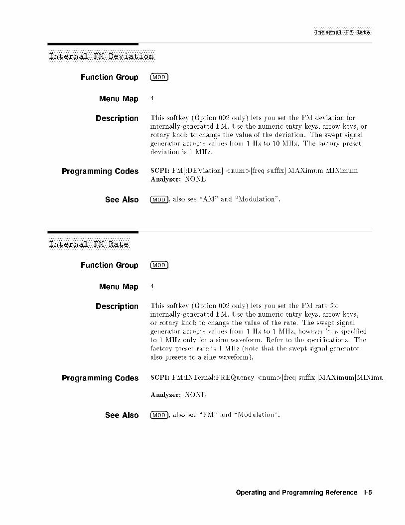
NNNNNNNNNNNNNNNNNNNNNNNNNNNNNNNNNNNNNNNNNNNNNNInternal FM Rate
aaaaaaaaaaaaaaaaaaaaaaaaaaaaaaaaaaaaaaaaaaaaaaaaaaaaaaaaaaaaaaaaaaaaaaaaaaaaaaaaaaaaaInternal FM Deviation
Function Group �MOD�
Menu Map 4
Description This softkey (Option 002 only) lets you set the FM deviation forinternally-generated FM. Use the numeric entry keys, arrow keys, orrotary knob to change the value of the deviation. The swept signalgenerator accepts values from 1 Hz to 10 MHz. The factory presetdeviation is 1 MHz.
Programming Codes SCPI: FM[:DEViation] <num>[freq su�x]jMAXimumjMINimumAnalyzer: NONE
See Also �MOD�, also see \AM" and \Modulation".
aaaaaaaaaaaaaaaaaaaaaaaaaaaaaaaaaaaaaaaaaaaaaaaaaaaaaaaaaaaaaaaaaInternal FM Rate
Function Group �MOD�
Menu Map 4
Description This softkey (Option 002 only) lets you set the FM rate forinternally-generated FM. Use the numeric entry keys, arrow keys,or rotary knob to change the value of the rate. The swept signalgenerator accepts values from 1 Hz to 1 MHz, however it is speci�edto 1 MHz only for a sine waveform. Refer to the speci�cations. Thefactory preset rate is 1 MHz (note that the swept signal generatoralso presets to a sine waveform).
Programming Codes SCPI: FM:INTernal:FREQuency <num>[freq su�x]jMAXimumjMINimu
Analyzer: NONE
See Also �MOD�, also see \FM" and \Modulation".
Operating and Programming Reference I-5
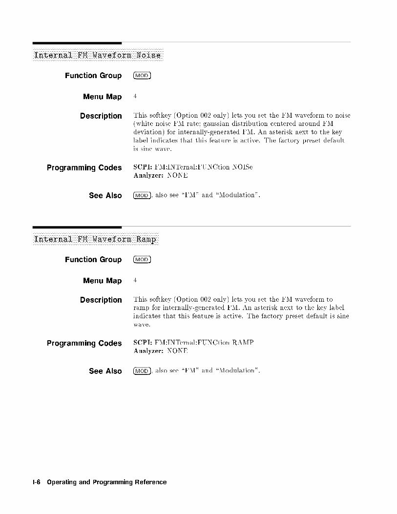
aaaaaaaaaaaaaaaaaaaaaaaaaaaaaaaaaaaaaaaaaaaaaaaaaaaaaaaaaaaaaaaaaaaaaaaaaaaaaaaaaaaaaaaaaaaaaaaaaaaaaaaaaInternal FM Waveform Noise
Function Group �MOD�
Menu Map 4
Description This softkey (Option 002 only) lets you set the FM waveform to noise(white noise FM rate; gaussian distribution centered around FMdeviation) for internally-generated FM. An asterisk next to the keylabel indicates that this feature is active. The factory preset defaultis sine wave.
Programming Codes SCPI: FM:INTernal:FUNCtion NOISeAnalyzer: NONE
See Also �MOD�, also see \FM" and \Modulation".
aaaaaaaaaaaaaaaaaaaaaaaaaaaaaaaaaaaaaaaaaaaaaaaaaaaaaaaaaaaaaaaaaaaaaaaaaaaaaaaaaaaaaaaaaaaaaaaaaaaaaInternal FM Waveform Ramp
Function Group �MOD�
Menu Map 4
Description This softkey (Option 002 only) lets you set the FM waveform toramp for internally-generated FM. An asterisk next to the key labelindicates that this feature is active. The factory preset default is sinewave.
Programming Codes SCPI: FM:INTernal:FUNCtion RAMPAnalyzer: NONE
See Also �MOD�, also see \FM" and \Modulation".
I-6 Operating and Programming Reference

NNNNNNNNNNNNNNNNNNNNNNNNNNNNNNNNNNNNNNNNNNNNNNNNNNNNNNNNNNNNNNNNNNNNNNNNNNNInternal FM Waveform Square
aaaaaaaaaaaaaaaaaaaaaaaaaaaaaaaaaaaaaaaaaaaaaaaaaaaaaaaaaaaaaaaaaaaaaaaaaaaaaaaaaaaaaaaaaaaaaaaaaaaaaInternal FM Waveform Sine
Function Group �MOD�
Menu Map 4
Description This softkey (Option 002 only) lets you set the FM waveform to sinewave for internally-generated FM. An asterisk next to the key labelindicates that this feature is active. Sine wave is the factory presetwaveform.
Programming Codes SCPI: FM:INTernal:FUNCtion SINusoidAnalyzer: NONE
See Also �MOD�, also see \FM" and \Modulation".
aaaaaaaaaaaaaaaaaaaaaaaaaaaaaaaaaaaaaaaaaaaaaaaaaaaaaaaaaaaaaaaaaaaaaaaaaaaaaaaaaaaaaaaaaaaaaaaaaaaaaaaaaaaaInternal FM Waveform Square
Function Group �MOD�
Menu Map 4
Description This softkey (Option 002 only) lets you set the FM waveform tosquare wave for internally-generated FM. An asterisk next to the keylabel indicates that this feature is active. The factory preset defaultis sine wave.
Programming Codes SCPI: FM:INTernal:FUNCtion SQUareAnalyzer: NONE
See Also �MOD�, also see \FM" and \Modulation".
Operating and Programming Reference I-7

aaaaaaaaaaaaaaaaaaaaaaaaaaaaaaaaaaaaaaaaaaaaaaaaaaaaaaaaaaaaaaaaaaaaaaaaaaaaaaaaaaaaaaaaaaaaaaaaaaaaaaaaaaaaaaaaaaaaInternal FM Waveform Triangle
Function Group �MOD�
Menu Map 4
Description This softkey (Option 002 only) lets you set the FM waveform totriangle wave for internally-generated FM. An asterisk next to thekey label indicates that this feature is active. The factory presetdefault is sine wave.
Programming Codes SCPI: FM:INTernal:FUNCtion TRIangleAnalyzer: NONE
See Also �MOD�, also see \FM" and \Modulation".
aaaaaaaaaaaaaaaaaaaaaaaaaaaaaaaaaaaaaaaaaaaaaaaaaaaaaaInternal Menu
Function Group �MOD�
Menu Map 4
Description This softkey (Option 002 only) lets you de�ne the parameters of theinternal pulse modulation.NNNNNNNNNNNNNNNNNNNNNNNNNNNNNNNNNNNNNNNNNNNNNNNNNNNNNNNNNNNNNNNNNNNNNNNNNNNNNNNNNNNNNNNNNNNNInternal Pulse Generator Width
Sets the width of the on portion of theinternally-generated pulse.NNNNNNNNNNNNNNNNNNNNNNNNNNNNNNNNNNNNNNNNNNNNNNNNNNNNNNNNNNNNNNNNNNNNNNNNNNNNNNNNNNNNNNNNN
Internal Pulse Generator Rate
Sets the repetition frequency of theinternally-generated pulse.NNNNNNNNNNNNNNNNNNNNNNNNNNNNNNNNNNNNNNNNNNNNNNNNNNNNNNNNNNNNNNNNNNNNNNNNNNNNNNNNNNNNNNNNNNNNNNN
Internal Pulse Generator Period
Sets the period of the internally-generated pulse.NNNNNNNNNNNNNNNNNNNNNNNNNNNNNNNNNNNNNNNNNNNNNNNNNNNNNNNNNNNNNNNNNNNNNNNNNNNNNNNNNNNNNNNNNNNNInternal Pulse Generator Delay
Delays the pulse from the trigger signal applied tothe external trigger.NNNNNNNNNNNNNNNNNNNNNNNNNNNNNNNNNNNNNNNNNNNNNNNNNNNNNNNNNNNNNNNNNNNNNNNNNN
Internal Pulse Mode Auto
Default mode of generating automatically-triggeredinternal pulses.
I-8 Operating and Programming Reference

NNNNNNNNNNNNNNNNNNNNNNNNNNNNNNNNNNNNNNNNNNNNNNNNNNNNNNNNNNNNNNNNNNNNNNNNNNNNNNNNNNNNNNInternal Pulse Generator Period
NNNNNNNNNNNNNNNNNNNNNNNNNNNNNNNNNNNNNNNNNNNNNNNNNNNNNNNNNNNNNNNNNNNNNNNNNNInternal Pulse Mode Gate
Turns on the internal pulse mode during thepositive cycle of the externally generated pulse.NNNNNNNNNNNNNNNNNNNNNNNNNNNNNNNNNNNNNNNNNNNNNNNNNNNNNNNNNNNNNNNNNNNNNNNNNNNNNNNNNNN
Internal Pulse Mode Trigger
Triggers on the leading edge of the external pulseinput.
Programming Codes SCPI: NONE, see the individual softkeys listed.Analyzer: NONE
See Also �MOD�, also see \Modulation" and \Pulse".
aaaaaaaaaaaaaaaaaaaaaaaaaaaaaaaaaaaaaaaaaaaaaaaaaaaaaaaaaaaaaaaaaaaaaaaaaaaaaaaaaaaaaaaaaaaaaaaaaaaaaaaaaaaaaaaaaaaaaaaaaaaaInternal Pulse Generator Period
Function Group �MOD�
Menu Map 4
Description This softkey (Option 002 only) lets you set a value for the internalpulse generator's pulse period. The pulse is adjustable from300 ns to 400 ms with 25 ns resolution. The factory preset defaultis 2 ms pulse period. When this feature is active, its current value isdisplayed in the active entry area.
Since period and rate are inversely related, if both are given values,only the last one will be applied which will cause the �rst one to berecalculated. Use the one that is convenient for your application. Forexample, if you set the pulse period, do not change the pulse rate(the swept signal generator automatically adjusts the rate to matchthe period).
Programming Codes SCPI: PULS:INTernal:PERiod <num>[time su�x]jMAXimumjMINimum
Analyzer: NONE
See Also �MOD�, also see \Pulse" and \Modulation".
Operating and Programming Reference I-9

aaaaaaaaaaaaaaaaaaaaaaaaaaaaaaaaaaaaaaaaaaaaaaaaaaaaaaaaaaaaaaaaaaaaaaaaaaaaaaaaaaaaaaaaaaaaaaaaaaaaaaaaaaaaaaaaaaaaInternal Pulse Generator Rate
Function Group �MOD�
Menu Map 4
Description This softkey (Option 002 only) lets you set a value for the internalpulse generator's pulse rate. The range of acceptable values is from2.5 Hz to 3.33 MHz. (These values are obtained by taking the inverseof the period.) The factory preset default is 500 Hz. When thisfeature is active, its current value is displayed in the active entryarea.
Since rate and period are inversely related, if both are given values,only the last one will be applied which will cause the �rst one to berecalculated. Use the one that is convenient for your application. Forexample, if you set the pulse rate, do not change the pulse period(the swept signal generator automatically adjusts the period tomatch the rate).
Programming Codes SCPI: PULM:INTernal:FREQuency <num>[freq su�x]jMAXimumjMINimum
Analyzer: NONE
See Also �MOD�, also see \Pulse" and \Modulation".
aaaaaaaaaaaaaaaaaaaaaaaaaaaaaaaaaaaaaaaaaaaaaaaaaaaaaaaaaaaaaaaaaaaaaaaaaaaaaaaaaaaaaaaaaaaaaaaaaaaaaaaaaaaaaaaaaaaaaaaaInternal Pulse Generator Width
Function Group �MOD�
Menu Map 4
Description This softkey (Option 002 only) lets you set a value for the internalpulse generator's pulse width. The pulse is adjustable from 25 nsto 400 ms with 25 ns resolution. The factory preset default is 1 mspulse width. If you set a value for the pulse width that is greaterthan the pulse period, the pulse period is recalculated to a valueequal to the pulse width plus 25 ns. When this feature is active, itscurrent value is displayed in the active entry area.
I-10 Operating and Programming Reference
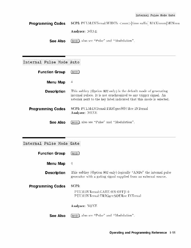
NNNNNNNNNNNNNNNNNNNNNNNNNNNNNNNNNNNNNNNNNNNNNNNNNNNNNNNNNNNNNNNNNNNInternal Pulse Mode Gate
Programming Codes SCPI: PULM:INTernal:WIDTh <num>[time su�x]jMAXimumjMINimu
Analyzer: NONE
See Also �MOD�, also see \Pulse" and \Modulation".
aaaaaaaaaaaaaaaaaaaaaaaaaaaaaaaaaaaaaaaaaaaaaaaaaaaaaaaaaaaaaaaaaaaaaaaaaaaaaaaaaaaaaaaaaaaaaaaaaInternal Pulse Mode Auto
Function Group �MOD�
Menu Map 4
Description This softkey (Option 002 only) is the default mode of generatinginternal pulses. It is not synchronized to any trigger signal. Anasterisk next to the key label indicated that this mode is selected.
Programming Codes SCPI: PULM:INTernal:TRIGger:SOURce INTernalAnalyzer: NONE
See Also �MOD�, also see \Pulse" and \Modulation".
aaaaaaaaaaaaaaaaaaaaaaaaaaaaaaaaaaaaaaaaaaaaaaaaaaaaaaaaaaaaaaaaaaaaaaaaaaaaaaaaaaaaaaaaaaaaaaaaaInternal Pulse Mode Gate
Function Group �MOD�
Menu Map 4
Description This softkey (Option 002 only) logically \ANDs" the internal pulsegenerator with a gating signal supplied from an external source.
Programming Codes SCPI:
PULM:INTernal:GATE ONjOFFj1j0PULM:INTernal:TRIGger:SOURce INTernal
Analyzer: NONE
See Also �MOD�, also see \Pulse" and \Modulation".
Operating and Programming Reference I-11
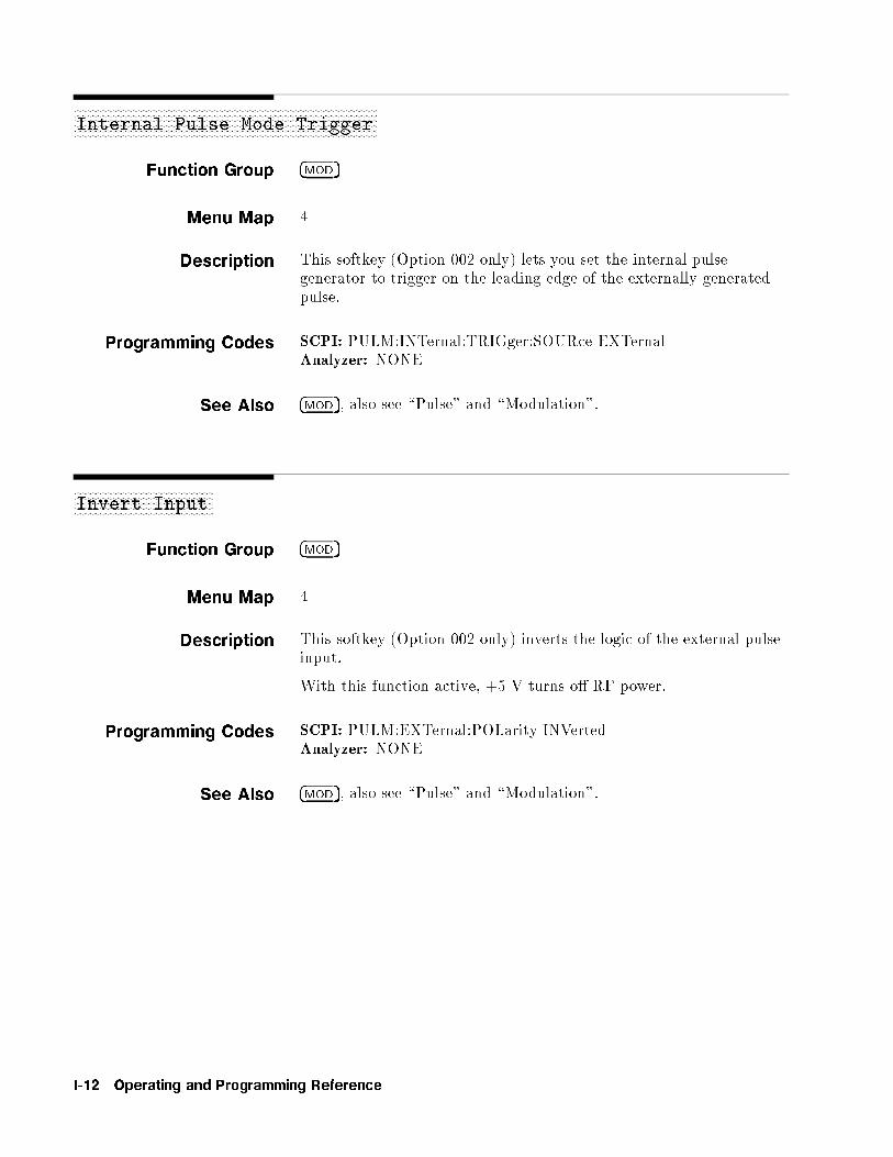
aaaaaaaaaaaaaaaaaaaaaaaaaaaaaaaaaaaaaaaaaaaaaaaaaaaaaaaaaaaaaaaaaaaaaaaaaaaaaaaaaaaaaaaaaaaaaaaaaaaaaaaaaaaaInternal Pulse Mode Trigger
Function Group �MOD�
Menu Map 4
Description This softkey (Option 002 only) lets you set the internal pulsegenerator to trigger on the leading edge of the externally generatedpulse.
Programming Codes SCPI: PULM:INTernal:TRIGger:SOURce EXTernalAnalyzer: NONE
See Also �MOD�, also see \Pulse" and \Modulation".
aaaaaaaaaaaaaaaaaaaaaaaaaaaaaaaaaaaaaaaaaaaaaaaaaaInvert Input
Function Group �MOD�
Menu Map 4
Description This softkey (Option 002 only) inverts the logic of the external pulseinput.
With this function active, +5 V turns o� RF power.
Programming Codes SCPI: PULM:EXTernal:POLarity INVertedAnalyzer: NONE
See Also �MOD�, also see \Pulse" and \Modulation".
I-12 Operating and Programming Reference
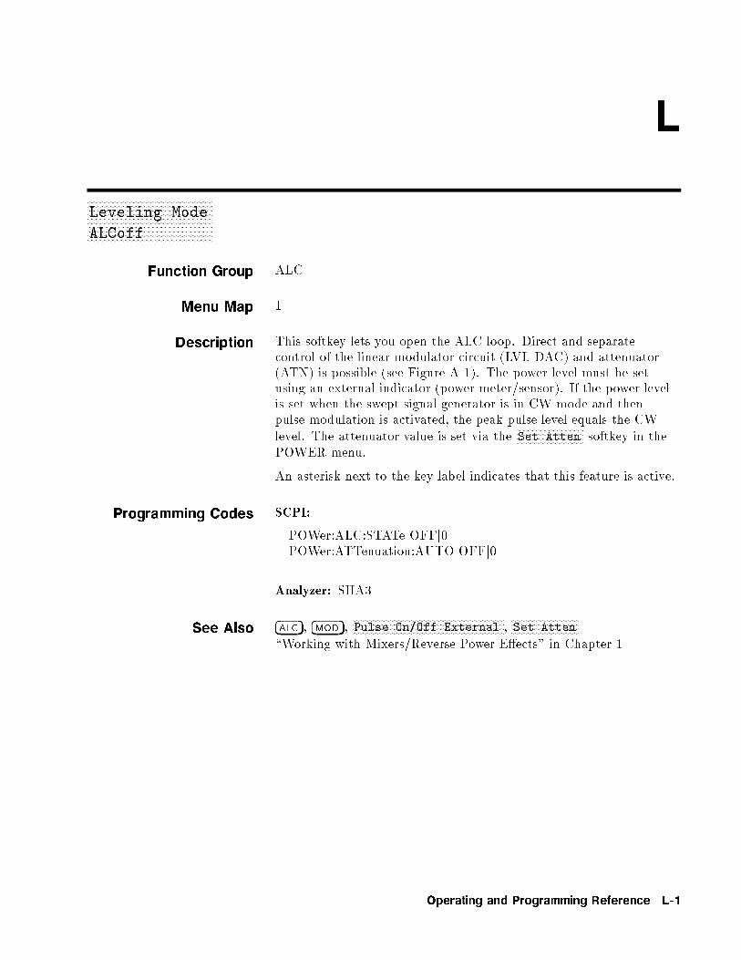
L
xFxFxFxFxFxFxFxFxFxFxFxFxFxFxFxFxFxFxFxFxFxFxFxFxFxFxFxFxFxFxFxFxFxFxFxFxFxFxFxFxFxFxFxFxFxFxFxFxFxFxFxFxFxF
Leveling Mode
ALCoff
Function Group ALC
Menu Map 1
Description This softkey lets you open the ALC loop. Direct and separatecontrol of the linear modulator circuit (LVL DAC) and attenuator(ATN) is possible (see Figure A-1). The power level must be setusing an external indicator (power meter/sensor). If the power levelis set when the swept signal generator is in CW mode and thenpulse modulation is activated, the peak pulse level equals the CWlevel. The attenuator value is set via the
NNNNNNNNNNNNNNNNNNNNNNNNNNNNNSet Atten softkey in the
POWER menu.
An asterisk next to the key label indicates that this feature is active.
Programming Codes SCPI:
POWer:ALC:STATe OFFj0POWer:ATTenuation:AUTO OFFj0
Analyzer: SHA3
See Also �ALC�, �MOD�,NNNNNNNNNNNNNNNNNNNNNNNNNNNNNNNNNNNNNNNNNNNNNNNNNNNNNNNNNNNNNNNNNPulse On/Off External ,
NNNNNNNNNNNNNNNNNNNNNNNNNNNNNSet Atten
\Working with Mixers/Reverse Power E�ects" in Chapter 1
Operating and Programming Reference L-1
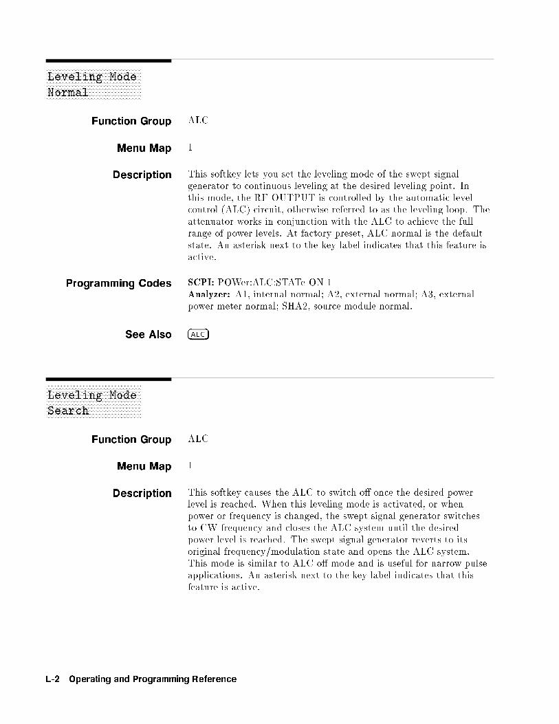
xFxFxFxFxFxFxFxFxFxFxFxFxFxFxFxFxFxFxFxFxFxFxFxFxFxFxFxFxFxFxFxFxFxFxFxFxFxFxFxFxFxFxFxFxFxFxFxFxFxFxFxFxFxF
Leveling Mode
Normal
Function Group ALC
Menu Map 1
Description This softkey lets you set the leveling mode of the swept signalgenerator to continuous leveling at the desired leveling point. Inthis mode, the RF OUTPUT is controlled by the automatic levelcontrol (ALC) circuit, otherwise referred to as the leveling loop. Theattenuator works in conjunction with the ALC to achieve the fullrange of power levels. At factory preset, ALC normal is the defaultstate. An asterisk next to the key label indicates that this feature isactive.
Programming Codes SCPI: POWer:ALC:STATe ONj1Analyzer: A1, internal normal; A2, external normal; A3, externalpower meter normal; SHA2, source module normal.
See Also �ALC�
xFxFxFxFxFxFxFxFxFxFxFxFxFxFxFxFxFxFxFxFxFxFxFxFxFxFxFxFxFxFxFxFxFxFxFxFxFxFxFxFxFxFxFxFxFxFxFxFxFxFxFxFxFxF
Leveling Mode
Search
Function Group ALC
Menu Map 1
Description This softkey causes the ALC to switch o� once the desired powerlevel is reached. When this leveling mode is activated, or whenpower or frequency is changed, the swept signal generator switchesto CW frequency and closes the ALC system until the desiredpower level is reached. The swept signal generator reverts to itsoriginal frequency/modulation state and opens the ALC system.This mode is similar to ALC o� mode and is useful for narrow pulseapplications. An asterisk next to the key label indicates that thisfeature is active.
L-2 Operating and Programming Reference
NNNNNNNNNNNNNNNNNNNNNNNNNNNNNNNNNNNNNNNNNNNNNNNNNNNNNNNNLeveling PointIntrnl
Programming Codes SCPI: POWer:ALC:STATe SEARchAnalyzer: SHA1
See Also �ALC�, Pulse Modulation\Working with Spectrum Analyzers/Reverse Power E�ects" inChapter 1
xFxFxFxFxFxFxFxFxFxFxFxFxFxFxFxFxFxFxFxFxFxFxFxFxFxFxFxFxFxFxFxFxFxFxFxFxFxFxFxFxFxFxFxFxFxFxFxFxFxFxFxFxFxFxFxFxF
Leveling Point
ExtDet
Function Group ALC
Menu Map 1
Description This softkey lets you set the swept signal generator to accept anexternal feedback connection from a negative-output diode detectorto level power. The EXT ALC BNC is the input connection for therequired signal. An asterisk next to the key label indicates that thisfeature is active.
Programming Codes SCPI:POWer:ALC[:SOURCce] DIODePOWer:ATTenuation:AUTO OFFj0Analyzer:A2
See Also �ALC�\Externally Leveling the Swept Signal Generator" in Chapter 1
xFxFxFxFxFxFxFxFxFxFxFxFxFxFxFxFxFxFxFxFxFxFxFxFxFxFxFxFxFxFxFxFxFxFxFxFxFxFxFxFxFxFxFxFxFxFxFxFxFxFxFxFxFxFxFxFxF
Leveling Point
Intrnl
Function Group ALC
Operating and Programming Reference L-3
NNNNNNNNNNNNNNNNNNNNNNNNNNNNNNNNNNNNNNNNNNNNNNNNNNNNNNNNLeveling PointIntrnl
Menu Map 1
Description This softkey lets you set the swept signal generator to level at theoutput of the directional coupler located inside the swept signalgenerator. An asterisk next to the key label indicates that thisfeature is active.
Programming Codes SCPI: POWer:ALC[:SOURce] INTernalAnalyzer: A1
See Also �ALC�
xFxFxFxFxFxFxFxFxFxFxFxFxFxFxFxFxFxFxFxFxFxFxFxFxFxFxFxFxFxFxFxFxFxFxFxFxFxFxFxFxFxFxFxFxFxFxFxFxFxFxFxFxFxFxFxFxF
Leveling Point
Module
Function Group ALC
Menu Map 1
Description This softkey lets you set the swept signal generator to level atthe output of an HP/Agilent 8355X series millimeter-wave sourcemodule. All models of the 8360 B-Series swept signal generator drivemm-wave source modules. High power models of 8360 drive themm-wave source modules directly and to speci�ed power levels.
An HP/Agilent 8349B power ampli�er is needed in othercon�gurations. The source module interface multi-pin connectorprovides the communication path between the swept signal generatorand mm-wave source module. An asterisk next to the key labelindicates that this feature is active.
Programming Codes SCPI: POWer:ALC[:SOURce] MMHeadAnalyzer: SHA2
See Also �ALC�, CONNECTORS\Externally Leveling the Swept Signal Generator" in Chapter 1
L-4 Operating and Programming Reference

LINE SWITCH
xFxFxFxFxFxFxFxFxFxFxFxFxFxFxFxFxFxFxFxFxFxFxFxFxFxFxFxFxFxFxFxFxFxFxFxFxFxFxFxFxFxFxFxFxFxFxFxFxFxFxFxFxFxFxFxFxF
Leveling Point
PwrMtr
Function Group ALC
Menu Map 1
Description This softkey lets you set the swept signal generator to level at thepower sensor of an external power meter. This mode of operationrequires a feedback connection from the power meter to the EXTALC BNC located on the swept signal generator. An asterisk next tothe key label indicates that this feature is active.
Programming Codes SCPI: POWer:ALC[:SOURce] PMETerAnalyzer: A3
See Also �ALC�, CONNECTORS\Externally Leveling the Swept Signal Generator" in Chapter 1
LINE SWITCH
Function Group NONE
Menu Map NONE
Description The line switch (on/o� switch) has two positions, o� or standby andon. If line power is connected to the swept signal generator and theline switch is set to o�, the swept signal generator is in the standbystate (amber LED on). Standby provides power to the internalfrequency standard oven.
When line power is connected and the line switch is set to on, theswept signal generator power supplies are enabled and a limitedself-test is initiated. The CPU self test is performed; power suppliesand the front panel processor are checked.
Programming Codes NONE
See Also \INSTALLATION" for information on fuses.\Error Messages" for information on messages displayed at power on.
Operating and Programming Reference L-5

aaaaaaaaaaaaaaaaaaaaaaaaaaaaaaaaaaaaaaList Menu
Function Group FREQUENCY
Menu Map 2
Description This softkey allows access to the frequency list functions.NNNNNNNNNNNNNNNNNNNNNNNNNNNNNNNNNNNNNNNNNNNNAuto Fill Incr Automatically creates a frequency list using the
user-speci�ed increment value.NNNNNNNNNNNNNNNNNNNNNNNNNNNNNNNNNNNNNNNNNNNNAuto Fill #Pts Automatically creates a frequency list
containing a user-speci�ed number of points.NNNNNNNNNNNNNNNNNNNNNNNNNNNNNNNNNNNNNNNNNNNNNNNAuto Fill Start Allows the entry of a start frequency for the
frequency list.NNNNNNNNNNNNNNNNNNNNNNNNNNNNNNNNNNNNNNNNNNNNAuto Fill Stop Allows the entry of a stop frequency for the
frequency list.NNNNNNNNNNNNNNNNNNNNNNNNNNNNNNNNNNNDelete Menu Reveals the frequency list delete menu.
NNNNNNNNNNNNNNNNNNNNNNNNNNNNNNNNNNNNNNNNNNNNNNNNNNEnter List Dwell Allows the entry of a dwell time for a frequency
point in the frequency list.NNNNNNNNNNNNNNNNNNNNNNNNNNNNNNNNNNNNNNNNNNNNNNNEnter List Freq Allows the entry of a frequency point into the
frequency list.NNNNNNNNNNNNNNNNNNNNNNNNNNNNNNNNNNNNNNNNNNNNNNNNNNEnter List Power Allows the entry of an ALC output power
correction value for a frequency in the frequencylist.NNNNNNNNNNNNNNNNNNNNNNNNNNNNNNNNNNNNNN
Global Dwell Automatically sets the dwell time for all pointsin the frequency list to a user-speci�ed value.NNNNNNNNNNNNNNNNNNNNNNNNNNNNNNNNNNNNNNNNN
Global Offset Automatically sets the ALC output powercorrection value for all points in the frequencylist to a user-speci�ed value.NNNNNNNNNNNNNNNNNNNNNNNNNNNNNNNNNNNNNN
Pt Trig Menu Reveals the frequency list in the point triggermenu.
A frequency list consists of two or more frequency points. Afrequency point can be any frequency value within the speci�edfrequency range of the swept signal generator and must be enteredbefore a value for either ALC output power o�set or dwell time isaccepted. The maximum number of frequency points in a frequencylist is 801.
Creating a Frequency List
There are two methods of constructing a frequency list:
1. Use theNNNNNNNNNNNNNNNNNNNNNNNNNNNNNNNNNNNNNNNNNNNNNNNEnter List Freq softkey to begin entering frequency
points. The list will be generated in the order the values areentered.
L-6 Operating and Programming Reference

NNNNNNNNNNNNNNNNNNNNNNNNNNList Menu
2. If the minimum and maximum frequencies of the swept signalgenerator frequency range are not the endpoints desired for thefrequency list, use the
NNNNNNNNNNNNNNNNNNNNNNNNNNNNNNNNNNNNNNNNNNNNNNNAuto Fill Start and
NNNNNNNNNNNNNNNNNNNNNNNNNNNNNNNNNNNNNNNNNNNNAuto Fill Stop
softkeys to de�ne the frequency list endpoints. Then, use eitherthe
NNNNNNNNNNNNNNNNNNNNNNNNNNNNNNNNNNNNNNNNNNNNAuto Fill Incr or
NNNNNNNNNNNNNNNNNNNNNNNNNNNNNNNNNNNNNNNNNNNNAuto Fill #Pts softkeys to create the
list. A list created by this method is ordered with the lowestfrequency as the �rst point and the highest frequency as the lastpoint of the frequency list.
Editing Frequency Points
To add a frequency point to the list, place the active entry arrow -->
where you want the next frequency point to appear. The frequencypoint is added directly after the value indicated by the arrow.
Lists created by the Auto Fill method are appended to an existinglist much the same way frequency points are added to a list. Thenewly created list is added between the frequency point indicated bythe active entry arrow and the point directly after it.
Note If adding a new list of frequencies causes the existing list to exceedthe maximum number of frequency points allowed (801), the new listis not appended to the existing list. The error message TOO MANY
LIST PTS REQUESTED is displayed.
To remove a frequency point and its associated o�set value and dwelltime, use the delete menu (
NNNNNNNNNNNNNNNNNNNNNNNNNNNNNNNNNNNNNNNNNNNNDelete Current ) softkey. To remove an
entire frequency list, use the delete menu, (NNNNNNNNNNNNNNNNNNNNNNNNNNNNNNNNDelete All ) softkey.
Editing ALC O�set and Dwell Time
Once a frequency point has been entered, you can assign an ALCo�set and a dwell time value. Use either the
NNNNNNNNNNNNNNNNNNNNNNNNNNNNNNNNNNNNNNNNNNNNNNNNNNEnter List Power
orNNNNNNNNNNNNNNNNNNNNNNNNNNNNNNNNNNNNNNNNNGlobal Offset softkey to enter o�set values. Use either theNNNNNNNNNNNNNNNNNNNNNNNNNNNNNNNNNNNNNNNNNNNNNNNNNN
Enter List Dwell orNNNNNNNNNNNNNNNNNNNNNNNNNNNNNNNNNNNNNNGlobal Dwell softkey to enter dwell time
values.
The editing softkeys of this menu are not accessible over GPIB.Frequency lists to be loaded over GPIB must �rst be created in thecontrolling program and then downloaded in their entirety to theswept signal generator.
Programming Codes SCPI:
LIST:FREQuency f<num>[freq su�x]jMAXimumjMINimumgLIST:[POWer]:CORRection f<num>[DB]jMAXimumjMINimumgLIST:DWELl f<num>[time su�x]jMAXimumjMINimumg
In the above three commands, the entries contained in fg can berepeated between 1 to 801 times.LIST:DWELl:POINts? [MAXimumjMINimum]LIST:FREQuency:POINts? [MAXimumjMINimum]
Operating and Programming Reference L-7
NNNNNNNNNNNNNNNNNNNNNNNNNNList Menu
LIST[:POWer]:CORRection:POINts? [MAXimumjMINimum]
In the above three commands, the swept signal generator respondswith the number of points for the named parameter that are in thelist array.
If a particular list is shorter than another, an error is generated uponexecution. An exception is made for the case where the shorter listis of length 1. In this case, the list of length 1 is treated as thoughit were a list of equal length, with all values the same. At *RST, alllists for the current state are cleared and reset to a single value.
Analyzer: NONE
See Also �RECALL�, �SAVE�,NNNNNNNNNNNNNNNNNNNNNNNNNNNNNNNNNNNNNNNNNNNNNNNSweep Mode List
\Creating and Using a Frequency List" in Chapter 1
xFxFxFxFxFxFxFxFxFxFxFxFxFxFxFxFxFxFxFxFxFxFxFxFxFxFxFxFxFxFxFxFxFxFxFxFxFxFxFxFxFxFxFxFxFxFxFxFxFxFxFxFxFxFxFxFxFxFxFxFxFxFxFxFxFxFxFxFxF
List Mode Pt Trig
Auto
Function Group FREQUENCY
Menu Map 2
Description This softkey lets you set the swept signal generator to automaticallystep through a frequency list, when the swept signal generator is insweep list mode.
Programming Codes SCPI: LIST:TRIGger:SOURce IMMediateAnalyzer: NONE
See AlsoNNNNNNNNNNNNNNNNNNNNNNNNNNNNNList Menu ,
NNNNNNNNNNNNNNNNNNNNNNNNNNNNNNNNNNNNNNPt Trig Menu ,
NNNNNNNNNNNNNNNNNNNNNNNNNNNNNNNNNNNNNNNNNNNNNNNSweep Mode List
\Creating and Using a Frequency List" in Chapter 1
L-8 Operating and Programming Reference

NNNNNNNNNNNNNNNNNNNNNNNNNNNNNNNNNNNNNNNNNNNNNNNNNNNNNNNNList Mode Pt TrigExt
xFxFxFxFxFxFxFxFxFxFxFxFxFxFxFxFxFxFxFxFxFxFxFxFxFxFxFxFxFxFxFxFxFxFxFxFxFxFxFxFxFxFxFxFxFxFxFxFxFxFxFxFxFxFxFxFxFxFxFxFxFxFxFxFxFxFxFxFxF
List Mode Pt Trig
Bus
Function Group FREQUENCY
Menu Map 2
Description This softkey lets you set the trigger point to be the GPIB. Whenthe swept signal generator receives an GPIB trigger, it steps to thenext frequency point of the frequency list, provided the swept signalgenerator is in sweep list mode.
Programming Codes SCPI: LIST:TRIGger:SOURce BUSAnalyzer: NONE
See AlsoNNNNNNNNNNNNNNNNNNNNNNNNNNNNNList Menu ,
NNNNNNNNNNNNNNNNNNNNNNNNNNNNNNNNNNNNNNPt Trig Menu ,
NNNNNNNNNNNNNNNNNNNNNNNNNNNNNNNNNNNNNNNNNNNNNNNSweep Mode List
\Creating and Using a Frequency List" in Chapter 1
xFxFxFxFxFxFxFxFxFxFxFxFxFxFxFxFxFxFxFxFxFxFxFxFxFxFxFxFxFxFxFxFxFxFxFxFxFxFxFxFxFxFxFxFxFxFxFxFxFxFxFxFxFxFxFxFxFxFxFxFxFxFxFxFxFxFxFxFxF
List Mode Pt Trig
Ext
Function Group FREQUENCY
Menu Map 2
Description This softkey lets you set the trigger point to be an external hardwaretrigger. When the swept signal generator receives an externalhardware trigger, it steps to the next frequency point of thefrequency list, provided the swept signal generator is in sweep listmode.
Programming Codes SCPI: LIST:TRIGger:SOURce EXTernalAnalyzer: NONE
See AlsoNNNNNNNNNNNNNNNNNNNNNNNNNNNNNList Menu ,
NNNNNNNNNNNNNNNNNNNNNNNNNNNNNNNNNNNNNNPt Trig Menu ,
NNNNNNNNNNNNNNNNNNNNNNNNNNNNNNNNNNNNNNNNNNNNNNNSweep Mode List
\Creating and Using a Frequency List" in Chapter 1
Operating and Programming Reference L-9
�LOCAL�
Function Group INSTRUMENT STATE
Menu Map NONE
Description This hardkey lets you cancel remote operation and return the sweptsignal generator to front panel operation. The front panel keys aredeactivated when the swept signal generator is operated remotely. Ifthe external controller executes a LOCAL LOCKOUT command,pressing the �LOCAL� key does not return the swept signal generator tofront panel control.
Programming Codes SCPI: LOCALAnalyzer: LOCAL
See Also NONE\Getting Started Programming" in Chapter 1\Programming Typical Measurements" in Chapter 1
L-10 Operating and Programming Reference
M
aaaaaaaaaaaaaaaaaaaaaaaaaaaaaaaaaaaaaaaaaaaaaaaaaaM1--M2 Sweep
Function Group MARKER
Menu Map 3
Description This softkey lets you set the swept signal generator to start sweepingat the frequency of marker 1 (M1), and stop sweeping at thefrequency of marker 2 (M2). M2 must have a higher frequency
value than M1. IfNNNNNNNNNNNNNNNNNNNNNNNNNNNNNNNNNNNNNNM1--M2 Sweep is activated when M2 is at a
lower frequency than M1, the values of M1 and M2 are permanentlyinterchanged. While this function is active, the start/stop frequenciesof the swept signal generator are changed to the values of M1 andM2. An asterisk next to the key label indicates this feature is active.
Programming Codes SCPI: SWEep:MARKer:STATe ONjOFFj1j0Analyzer: MP1 function on, MP0 function o�.
See AlsoNNNNNNNNNNNNNNNNNNNNNNNNNNNNNMarker M1 ,
NNNNNNNNNNNNNNNNNNNNNNNNNNNNNNNNNNNNNNNNNNNNNNNNNNStart=M1 Stop=M2
\Marker Operation" in Chapter 1\Programming Typical Measurements" in Chapter 1
aaaaaaaaaaaaaaaaaaaaaaaaaaaaaaaaaaaaaaaaaaaaaaaaaaManual Sweep
Function Group SWEEP
Menu Map 7
Description This softkey lets you set the swept signal generator to the manualsweep mode of operation. Depending on what parameter is sweeping,you can use either the rotary knob or the ARROW keys to manuallysweep between the start/stop limits. In manual sweep mode, theswept signal generator does not automatically retrace at the sweepend point (the user must turn the rotary knob to retrace), and thegreen SWEEP LED does not light. The resolution of the rotaryknob is 0.1% of the sweep span in either start/stop or CF/�F mode.The resolution of the �*� and �+� arrow keys are dependent on the
Operating and Programming Reference M-1

NNNNNNNNNNNNNNNNNNNNNNNNNNNNNNNNNNNManual Sweep
resolution de�ned by the �(� and �)� keys. Frequencies in themanual sweep mode are synthesized, just as they are in CW mode.
There are two major di�erences between manual sweep and a sweepgenerated by activating the CW function and rotating the rotaryknob or pressing the ARROW keys.
1. The sweep output voltage ramp is 0 to +10 V in both modes,but in CW mode, 0 V corresponds to lowest frequency of theswept signal generator frequency range and +10 V correspondsto the highest frequency of the range. In manual sweep mode,0 V corresponds to the start frequency speci�ed and +10 Vcorresponds to the stop frequency speci�ed. In both cases, thesweep voltage at intermediate frequencies is a linear interpolationof the frequency span. For example, a frequency half-way betweenthe start/stop limits has a sweep voltage of 5 V.
2. The bandcross points in CW mode occur at 2.0, 7, 13.5, 20, 25.5,and 32 GHz.
In manual sweep mode the bandcrossing points have 200 MHz of exibility, that is automatically used by the swept signal generatorfor optimum performance. For example, a 2.0 to 7.1 GHz sweepcould be accomplished without any band changes in manual sweepmode.
Programming Codes SCPI: SWEep:MODE MANualjAUTOThis is the command for frequency manual sweep.
POWer:MODE SWEepPOWer:SPAN <num>[lvl su�x]jMAXimumjMINimumThis is the command for power manual sweep.
LIST:MODE MANualThis is the command for manual list sweep.Analyzer: S3
See AlsoNNNNNNNNNNNNNNNNNNNNNNNNNNNNNNNNNNNPower Sweep ,
NNNNNNNNNNNNNNNNNNNNNNNNNNNNNNNNNNNNNNNNNNNNNNNSweep Mode List
\Continuous, Single, and Manual Sweep Operation" in Chapter 1
M-2 Operating and Programming Reference

�MARKER�
�MARKER�
Function Group MENU SELECT
Menu Map 3
Description This hardkey allows access to the marker functions.NNNNNNNNNNNNNNNNNNNNNNNNNNNNNNNNNNNNNNAmpl Markers Causes the swept signal generator to display
markers as an amplitude pulse.NNNNNNNNNNNNNNNNNNNNNNNNNNNNNNNNNNNNNNNNNCenter=Marker Changes the swept signal generator's center
frequency to the value of the most recentlyactivated marker.NNNNNNNNNNNNNNNNNNNNNNNNNNNNNNNNNNNNNN
Delta Marker Display the frequency di�erence between theactive marker and the marker designated by thesoftkey
NNNNNNNNNNNNNNNNNNNNNNNNNNNNNNNNNNNNNNNNNDelta Mkr Ref .
NNNNNNNNNNNNNNNNNNNNNNNNNNNNNNNNNNNNNNNNNDelta Mkr Ref Reveals the softkeys in the delta marker
reference menu.NNNNNNNNNNNNNNNNNNNNNNNNNNNNNNNNNNNNNNM1--M2 Sweep Causes the swept signal generator to sweep from
M1 to M2.NNNNNNNNNNNNNNNNNNNNNNNNNNNNNMarker M1 Makes M1 frequency the active function.NNNNNNNNNNNNNNNNNNNNNNNNNNNNNMarker M2 Makes M2 frequency the active function.
NNNNNNNNNNNNNNNNNNNNNNNNNNNNNMarker M3 Makes M3 frequency the active function.
NNNNNNNNNNNNNNNNNNNNNNNNNNNNNMarker M4 Makes M4 frequency the active function.
NNNNNNNNNNNNNNNNNNNNNNNNNNNNNMarker M5 Makes M5 frequency the active function.
NNNNNNNNNNNNNNNNNNNNNNNNNNNNNNNNNNNNNNNNNNNNNNNMarkers All Off Turns o� all markers.NNNNNNNNNNNNNNNNNNNNNNNNNNNNNNNNNNNNNNNNNNNNNNNNNNStart=M1 Stop=M2 Changes the swept signal generator start and
stop frequencies to the values of M1 and M2.
The markers are functional whenever an asterisk appears next to thekey label, but only one marker can be active at a time. The activemarker is indicated in the active entry area.
See Also Softkeys listed above.\Marker Operation" in Chapter 1\Programming Typical Measurements" in Chapter 1
Operating and Programming Reference M-3

aaaaaaaaaaaaaaaaaaaaaaaaaaaaaaaaaaaaaaMarker M1
Function Group MARKER
Menu Map 3
Description The softkeys labeledNNNNNNNNNNNNNNNNNNNNNNNNNNNNNMarker M1 through
NNNNNNNNNNNNNNNNNNNNNNNNNNNNNMarker M5 function
identically. The softkey turns the marker o�/on. When an asteriskappears next to the key label, it indicates that the marker is on, butnot necessarily active. A marker is only active when it is indicated inthe active entry area.
The active entry area displays the active marker and its frequencyvalue. Use the rotary knob, the ARROW keys, or the entry keys toset the frequency. Markers are displayed normally as Z-axis intensitydots, but can be changed to amplitude pulses (
NNNNNNNNNNNNNNNNNNNNNNNNNNNNNNNNNNNNNNAmpl Markers ).
When a marker is turned o�, the frequency value of that markeris retained in memory. If the marker is reactivated, the storedfrequency value is recalled for that marker.
The frequency value of M1 and of M2 can also be used to de�neparameters in two other marker features:
NNNNNNNNNNNNNNNNNNNNNNNNNNNNNNNNNNNNNNM1--M2 Sweep andNNNNNNNNNNNNNNNNNNNNNNNNNNNNNNNNNNNNNNNNNNNNNNNNNN
Start=M1 Stop=M2 .
Programming Codes SCPI:
MARKer[1][:FREQuency] <num>[freq su�x] orMAXimumjMINimumMARKer[1]:STATe ONjOFFj1j0
Analyzer: M1 function on, M0 function o�.
See AlsoNNNNNNNNNNNNNNNNNNNNNNNNNNNNNNNNNNNNNNAmpl Markers ,
NNNNNNNNNNNNNNNNNNNNNNNNNNNNNNNNNNNNNNM1--M2 Sweep , �MARKER�,
NNNNNNNNNNNNNNNNNNNNNNNNNNNNNNNNNNNMkrRef Menu ,NNNNNNNNNNNNNNNNNNNNNNNNNNNNNNNNNNNNNNNNNNNNNNNNNN
Start=M1 Stop=M2
\Marker Operation" in Chapter 1\Programming Typical Measurements" in Chapter 1
M-4 Operating and Programming Reference

NNNNNNNNNNNNNNNNNNNNNNNNNNMarker M3
aaaaaaaaaaaaaaaaaaaaaaaaaaaaaaaaaaaaaaMarker M2
Function Group MARKER
Menu Map 3
Description SeeNNNNNNNNNNNNNNNNNNNNNNNNNNNNNMARKER M1
Programming Codes SCPI:
MARKer2[:FREQuency] <num>[freq su�x] orMAXimumjMINimumMARKer2:STATe ONjOFFj1j0
Analyzer: M2 function on, M0 function o�.
See AlsoNNNNNNNNNNNNNNNNNNNNNNNNNNNNNNNNNNNNNNAmpl Markers ,
NNNNNNNNNNNNNNNNNNNNNNNNNNNNNNNNNNNNNNM1--M2 Sweep , �MARKER�,
NNNNNNNNNNNNNNNNNNNNNNNNNNNNNNNNNNNMkrRef Menu ,NNNNNNNNNNNNNNNNNNNNNNNNNNNNNNNNNNNNNNNNNNNNNNNNNN
Start=M1 Stop=M2
\Marker Operation" in Chapter 1\Programming Typical Measurements" in Chapter 1
aaaaaaaaaaaaaaaaaaaaaaaaaaaaaaaaaaaaaaMarker M3
Function Group MARKER
Menu Map 3
Description SeeNNNNNNNNNNNNNNNNNNNNNNNNNNNNNMARKER M1
Programming Codes SCPI:
MARKer3[:FREQuency] <num>[freq su�x] orMAXimumjMINimumMARKer3:STATe ONjOFFj1j0
Analyzer: M3 function on, M0 function o�.
See AlsoNNNNNNNNNNNNNNNNNNNNNNNNNNNNNNNNNNNNNNAmpl Markers , �MARKER�,
NNNNNNNNNNNNNNNNNNNNNNNNNNNNNNNNNNNMkrRef Menu
\Marker Operation" in Chapter 1\Programming Typical Measurements" in Chapter 1
Operating and Programming Reference M-5

aaaaaaaaaaaaaaaaaaaaaaaaaaaaaaaaaaaaaaMarker M4
Function Group MARKER
Menu Map 3
Description SeeNNNNNNNNNNNNNNNNNNNNNNNNNNNNNMARKER M1
Programming Codes SCPI:
MARKer4[:FREQuency] <num>[freq su�x] orMAXimumjMINimumMARKer4:STATe ONjOFFj1j0
Analyzer: M4 function on, M0 function o�.
See AlsoNNNNNNNNNNNNNNNNNNNNNNNNNNNNNNNNNNNNNNAmpl Markers , �MARKER�,
NNNNNNNNNNNNNNNNNNNNNNNNNNNNNNNNNNNMkrRef Menu
\Marker Operation" in Chapter 1\Programming Typical Measurements" in Chapter 1
aaaaaaaaaaaaaaaaaaaaaaaaaaaaaaaaaaaaaaMarker M5
Function Group MARKER
Menu Map 3
Description SeeNNNNNNNNNNNNNNNNNNNNNNNNNNNNNMARKER M1
Programming Codes SCPI:
MARKer5[:FREQuency] <num>[freq su�x] orMAXimumjMINimumMARKer5:STATe ONjOFFj1j0
Analyzer: M5 function on, M0 function o�.
See AlsoNNNNNNNNNNNNNNNNNNNNNNNNNNNNNNNNNNNNNNAmpl Markers , �MARKER�,
NNNNNNNNNNNNNNNNNNNNNNNNNNNNNNNNNNNMkrRef Menu
\Marker Operation" in Chapter 1\Programming Typical Measurements" in Chapter 1
M-6 Operating and Programming Reference
NNNNNNNNNNNNNNNNNNNNNNNNNNNNNNNNNNNNNNNNNNNNNNMeasure Corr All
aaaaaaaaaaaaaaaaaaaaaaaaaaaaaaaaaaaaaaaaaaaaaaaaaaaaaaaaaaaaaMarkers All Off
Function Group MARKER
Menu Map 3
Description This softkey lets you turn all the markers o�. The frequency valuegiven to the markers remains in memory and will be recalled whenthe marker softkeys are pressed again. Softkeys
NNNNNNNNNNNNNNNNNNNNNNNNNNNNNNNNNNNNNNAmpl Markers ,NNNNNNNNNNNNNNNNNNNNNNNNNNNNNNNNNNNNNNNNN
Center=Marker , andNNNNNNNNNNNNNNNNNNNNNNNNNNNNNNNNNNNNNNM1--M2 Sweep are not a�ected by turning the
markers o�. The function (or the frequency values) is retained as theswept signal generator settings.
Programming Codes SCPI: MARKer:AOFFAnalyzer: SHM0
See AlsoNNNNNNNNNNNNNNNNNNNNNNNNNNNNNNNNNNNNNNAmpl Markers ,
NNNNNNNNNNNNNNNNNNNNNNNNNNNNNNNNNNNNNNNNNCenter=Marker ,
NNNNNNNNNNNNNNNNNNNNNNNNNNNNNNNNNNNNNNM1--M2 Sweep , �MARKER�
\Marker Operation" in Chapter 1\Programming Typical Measurements" in Chapter 1
aaaaaaaaaaaaaaaaaaaaaaaaaaaaaaaaaaaaaaaaaaaaaaaaaaaaaaaaaaaaaaaaaMeasure Corr All
Function Group POWER
Menu Map 5
Description This softkey enables the swept signal generator to act as a controllerto command an HP/Agilent 437B power meter to measure atnesscorrection values at all frequency points de�ned in the atness array.
Programming Codes SCPI: NONEAnalyzer: NONE
See AlsoNNNNNNNNNNNNNNNNNNNNNNNNNNNNNNNNNNNNNNFltness Menu ,
NNNNNNNNNNNNNNNNNNNNNNNNNNNNNNNNNNNNNNNNNMtr Meas Menu
\Creating and Applying the User Flatness Correction Array" inChapter 1
Operating and Programming Reference M-7
xFxFxFxFxFxFxFxFxFxFxFxFxFxFxFxFxFxFxFxFxFxFxFxFxFxFxFxFxFxFxFxFxFxFxFxFxFxFxFxFxFxFxFxFxFxFxFxFxFxF
Measure Corr
Current
Function Group POWER
Menu Map 5
Description This softkey lets you enable the swept signal generator to act asa controller to command an HP/Agilent 437B power meter tomeasure a single atness correction value at the current atness arrayfrequency.
Programming Codes SCPI: NONEAnalyzer: NONE
See AlsoNNNNNNNNNNNNNNNNNNNNNNNNNNNNNNNNNNNNNNFltness Menu ,
NNNNNNNNNNNNNNNNNNNNNNNNNNNNNNNNNNNNNNNNNMtr Meas Menu
\Creating and Applying the User Flatness Correction Array" inChapter 1
xFxFxFxFxFxFxFxFxFxFxFxFxFxFxFxFxFxFxFxFxFxFxFxFxFxFxFxFxFxFxFxFxFxFxFxFxFxFxFxFxFxFxFxFxFxFxFxFxFxF
Measure Corr
Undef
Function Group POWER
Menu Map 5
Description This softkey lets you enable the swept signal generator to act as acontroller to command an HP/Agilent 437B power meter to measure atness correction values for those frequency points of the atnessarray that do not have correction values assigned.
Programming Codes SCPI: NONEAnalyzer: NONE
See AlsoNNNNNNNNNNNNNNNNNNNNNNNNNNNNNNNNNNNNNNFltness Menu ,
NNNNNNNNNNNNNNNNNNNNNNNNNNNNNNNNNNNNNNNNNMtr Meas Menu
\Creating and Applying the User Flatness Correction Array" inChapter 1
M-8 Operating and Programming Reference
NNNNNNNNNNNNNNNNNNNNNNNNNNNNNNNNNNNNNNNNNNNMeter On/Off AM
aaaaaaaaaaaaaaaaaaaaaaaaaaaaaaaaaaaaaaaaaaMeter Adrs
Function Group SYSTEM
Menu Map 8
Description In cases where the swept signal generator is capable of acting as acontroller to an HP/Agilent 437B power meter, this softkey enablesyou to set the programming address of the power meter. The addressvalue can be set from 0 to 30, with the factory default address set at13. The address value is stored in non-volatile memory.
Programming Codes SCPI: DIAGnostics:INSTrument:PMETer:ADDRess <num>Analyzer: NONE
See AlsoNNNNNNNNNNNNNNNNNNNNNNNNNNNNNNNNAdrss Menu
\Optimizing Swept Signal Generator Performance" in Chapter 1Chapter 3
aaaaaaaaaaaaaaaaaaaaaaaaaaaaaaaaaaaaaaaaaaaaaaaaaaaaaaaaaaaaaMeter On/Off AM
Function Group �MOD�
Menu Map 4
Description This softkey (Option 002 only) lets you display the value of the depthof the externally-generated amplitude modulation.
Programming Codes SCPI: MEASure:AM?Analyzer: NONE
See Also �MOD�, also see \AM" and \Modulation".
Operating and Programming Reference M-9

aaaaaaaaaaaaaaaaaaaaaaaaaaaaaaaaaaaaaaaaaaaaaaaaaaaaaaaaaaaaaMeter On/Off FM
Function Group �MOD�
Menu Map 4
Description This softkey (Option 002 only) lets you display the frequencydeviation produced by the externally-generated frequencymodulation.
Programming Codes SCPI: MEASure:FM?Analyzer: NONE
See Also �MOD�, also see \FM" and \Modulation".
�MOD�
Function Group MENU SELECT
Menu Map 4
Description This hardkey allows access to the modulation functions. Thefollowing types of modulation are available:
AM Amplitude modulation is accepted from an externalsource at the AM connector. The AM can bescaled either linearly or exponentially. Swept signalgenerators with Option 002 also have the capabilityof internally synthesizing amplitude modulation insine, square, triangle, ramp, or noise waveforms.Deep AM (a distortion reduction mode) can beselected for use when operating at a deep amplitudemodulation level.
FM Frequency modulation is accepted from an externalsource at the FM connector. The FM can be eitherAC-or DC-coupled. Swept signal generators withOption 002 also have the capability of internallysynthesizing frequency modulation in sine, square,triangle, ramp, or noise waveforms.
M-10 Operating and Programming Reference

NNNNNNNNNNNNNNNNNNNNNNNNNNNNNNNNNNNNNNNNNNNNNNModOut On/Off AM
Pulse Pulse modulation is accepted from an externalsource at the PULSE connector. In addition,pulse modulation can also be internally generated.The pulse is adjustable in standard swept signalgenerators with 1.0 �s resolution. Swept signalgenerators can also produce a 27.778 kHz squarewave for use with HP/Agilent scalar networkanalyzers. Swept signal generators with Option 002generate a synthesized pulse that is adjustable with25 ns resolution.
Additional information is available under \Modulation", or refer tothe type of modulation by name (AM, FM, Pulse).
See Also \Modulation"
aaaaaaaaaaaaaaaaaaaaaaaaaaaaaaaaaaaaaaaaaaaaaaaaaaaaaaaaaaaaaaaaaModOut On/Off AM
Function Group �MOD�
Menu Map 4
Description This softkey (Option 002 only) lets you output the internally-generated amplitude modulation waveforms to the rear panelAM/FM OUTPUT connector. When scaled linearly at 100%/V, themaximum output voltage is +1 V and the minimum output voltage is�1 V.
Programming Codes SCPI:
MODulation:OUTput:SOURce AMMODulation:OUTput:STATe ONjOFFj1j0
Analyzer: NONE
See Also �MOD�, also see \AM" and \Modulation".
Operating and Programming Reference M-11

aaaaaaaaaaaaaaaaaaaaaaaaaaaaaaaaaaaaaaaaaaaaaaaaaaaaaaaaaaaaaaaaaModOut On/Off FM
Function Group �MOD�
Menu Map 4
Description This softkey (Option 002 only) lets you output the internally-generated frequency modulation waveforms to the rear panel AM/FMOUTPUT connector. When scaled exponentially at 10 dB/V, themaximum output voltage is o�set to 0 V and the minimum voltagelevel is �4 V.
Programming Codes SCPI:
MODulation:OUTput:SOURce FMMODulation:OUTput:STATe ONjOFFj1j0
Analyzer: NONE
See Also �MOD�, also see \FM" and \Modulation".
M-12 Operating and Programming Reference
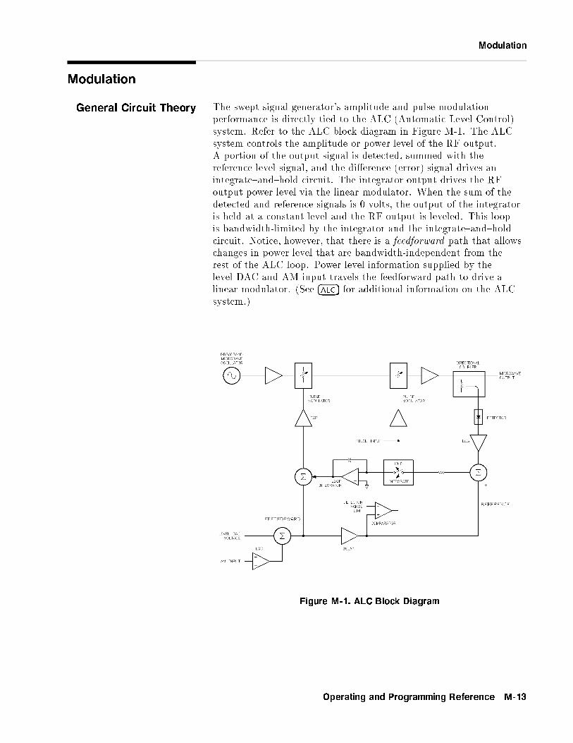
Modulation
Modulation
General Circuit Theory The swept signal generator's amplitude and pulse modulationperformance is directly tied to the ALC (Automatic Level Control)system. Refer to the ALC block diagram in Figure M-1. The ALCsystem controls the amplitude or power level of the RF output.A portion of the output signal is detected, summed with thereference level signal, and the di�erence (error) signal drives anintegrate{and{hold circuit. The integrator output drives the RFoutput power level via the linear modulator. When the sum of thedetected and reference signals is 0 volts, the output of the integratoris held at a constant level and the RF output is leveled. This loopis bandwidth-limited by the integrator and the integrate{and{holdcircuit. Notice, however, that there is a feedforward path that allowschanges in power level that are bandwidth-independent from therest of the ALC loop. Power level information supplied by thelevel DAC and AM input travels the feedforward path to drive alinear modulator. (See �ALC� for additional information on the ALCsystem.)
Figure M-1. ALC Block Diagram
Operating and Programming Reference M-13
AmplitudeModulation
Amplitude modulation can be accepted from an external source atthe AM connector or can be internally generated by swept signalgenerators with Option 002. The damage level of the AM input is�15 V DC. The input impedance of the AM connector is 50 .A jumper on the A10 ALC board allows you to change the inputimpedance to 2 k (See \Adjustments" in the Agilent Technologies8360 B-Series Swept Signal Generator/8360 L-Series Swept CWGenerator Service Guide.) The AM can be scaled either linearly at100% per volt or exponentially at 10 dB per volt.
When internal AM is chosen (Option 002), the rate and depth are setby softkeys in the AM menu. The waveform menu provides a choiceof sine, square, triangle, ramp, or noise waveforms. The monitormenu lets you output the internally generated modulation waveformsto the rear panel AM/FM OUTPUT connector. The AM output isscaled the same as it is generated, either 100%/V or 10 dB/V. Thisconnector can drive 50 or greater. The monitor menu also lets youdisplay the value of the AM depth.
UNLVLED Message
The maximum leveled output is limited by the swept signalgenerator's maximum leveled output power speci�cation. (Individualswept signal generators may be capable of greater leveled outputpower; the unleveled message indicates the actual limit.) Amplitudemodulation adds to and subtracts from the reference RF power level.If an UNLVLED message appears on the display, you may be tryingto modulate beyond the swept signal generator's maximum outputpower capability.
OVRMOD Message
The maximum AM depth is limited to approximately 90% by thedetector's ability to sense low power levels. If you try to amplitudemodulate too deep without using deep AM mode (explained later),you will see an OVRMOD message displayed on the message line. Also,if you modulate below �20 dBm ALC level without using deep AMmode or below �50 dBm with deep AM or search ALC mode, youwill see an OVRMOD message.
Dynamic Range
The ALC and attenuator combination (when an optional attenuatoris present) are automatically set by the swept signal generator tokeep the ALC in its most accurate range (0 to �10 dBm). This iscalled the coupled attenuator operating mode.
For applications where modulating across an attenuation switch pointis undesirable, you can uncouple the attenuator and manually set thepower level of the ALC and the attenuator.
For example, setting the power level to 0 dBm in coupled mode willgive an ALC level of 0 dBm and 0 dB of attenuation. In uncoupledmode, the attenuator can be set to 10 dB and the ALC to +10 dBm,
M-14 Operating and Programming Reference

Amplitude Modulation
giving 0 dBm output power and greater AM depth potential. TheALC can now be varied over its entire range and the attenuatorremains at a �xed level.
Uncoupled mode can also be used for the following:
To increase the available AM depth if you are modulating near theminimum power range of the ALC loop.
To o�set the power sweep range.
To reduce AM noise by operating at a higher ALC level.
AM Rate
The maximum AM rate available is limited by the bandwidth ofthe components in the RF path. At rates of about 100 kHz, theintegrator can no longer respond so the ALC loop is e�ectivelyopened. The feedforward path provides the capability to modulate atmuch faster rates.
RF components in the ALC loop limit the ALC bandwidth to250 kHz. High power and Option 006 swept signal generators are alsolimited to 100 kHz by the components in the RF path. Swept signalgenerators with frequency doublers (A32) are limited by the 100 kHzbandwidth of the doubler for carrier frequencies greater than 20 GHz.Note that due to the feedforward scheme, AM bandwidth is nota�ected when amplitude and pulse modulation are simultaneouslyactivated.
Deep AM
Deep AM mode is a means of reducing distortion when the desiredAM depth is very deep (greater than 90%) or when modulating belowan ALC level of �20 dBm. Amplitude modulation is summed withthe reference level signal. The detected signal is compared to thereference. Therefore, the ALC loop should follow the AM input.However, the detector's ability to sense low power levels limits themaximum AM depth. When the modulation signal reduces theoutput power level to a level which is below the detector's rangelimit, the error signal generated sends the integrator to rail, resultingin gross AM distortion. This is where deep AM mode should be used.
Deep AM engages a comparator circuit (see Figure M-1) to sense thepower level of the detected signal. When the signal level is out of thedetector's range, the loop integrator switch opens (opening the ALCloop). The output of the integrator is frozen, applying a constantdrive to the modulator. Since the modulator's most linear range isat low power levels, the AM envelope distortion is minimal. Whenthe comparator senses a signal that is within the detector's range, theintegrator switch is closed, re-engaging ALC loop leveling.
Figure M-2 shows the leveled AM characteristics in the di�erentmodes. The maximum leveled output with ALC engaged is shown asthe swept signal generator's maximum leveled output speci�cation.(Individual swept signal generators may have more power; watch
Operating and Programming Reference M-15

Amplitude Modulation
for an UNLVLED message.) The minimum level is limited by thedetector's range (approximately �20 dBm). With deep AM engaged,the minimum level (where the ALC loop is opened) is set to�13 dBm. This guarantees that the detector can still sense the signallevel with no distortion. With the ALC loop open, the minimumlevel is limited by the modulator's range to approximately �50 dBm.
Figure M-2. Power Accuracy Over the AM Dynamic Range
Calibrating the Linear Modulator
The AM bandwidth calibration feature calibrates the linearmodulator gain at the current CW frequency. This results in moreaccurate performance in deep AM mode when the ALC loop isopened. Figure M-2 shows the calibrated response of the modulatorcompared to the uncalibrated response. If you choose to calibrate\Always", the swept signal generator will automatically perform thecalibration whenever you change the CW frequency. Although thisfeature provides more accurate performance, note that it also slowsthe frequency switching time by 20 ms.
ALC Bandwidth
Since the ALC loop is open at power levels less than �13 dBm indeep AM mode, power levels at very slow AM rates are subject tointegrate{and{hold drift of typically 0.25 dB/s. Setting the ALCbandwidth to low reduces drift by a factor of 10 by switching a largercapacitor into the integrator circuit. The larger capacitor reduces thee�ects of leakage on the integrator. The ALC bandwidth defaultsat factory preset to the auto selection which normally selects theappropriate bandwidth (high or low) for your application. However,in this case (modulating with deep AM at a slow rate), auto modewould have set the ALC bandwidth to high where a setting of lowwould decrease drift. To make the bandwidth selection, the sweptsignal generator determines which functions are activated such as
M-16 Operating and Programming Reference
FM Modulation
frequency list mode, step sweep mode, search leveling mode, sweepfrequency mode, AM or pulse modulation, among others. (For acomplete explanation of the selection sequence, see \Getting Started,Advanced".)
FM Modulation Frequency modulation can be accepted from an external source atthe FM connector or can be internally generated by swept signalgenerators with Option 002. The damage level of the FM input is�15 V DC. The input impedance is set to 50 . A jumper on theA11 FM Driver board allows you to change the input impedance to600 . (See \Adjustments" in the Agilent Technologies 8360 B-SeriesSwept Signal Generator/8360 L-Series Swept CW Generator ServiceGuide .) The FM sensitivity can be scaled to either 100 kHz/V,1 MHz/V, or 10 MHz/V.
When internal FM is chosen (Option 002), the rate and deviationare set by softkeys in the FM menu. The waveform menu providesa choice of sine, square, triangle, ramp, or noise waveforms. Themonitor menu lets you output the internally generated modulationwaveforms to the rear panel AM/FM OUTPUT connector. Thescale of the FM output depends on the FM deviation chosen. Thefollowing table shows the scale versus deviation. The monitor menualso lets you display the value of the FM deviation.
Internal
FM Deviation
FM Scale
1 Hz to � 100 kHz 100 kHz/V
> 200 kHz to � 2 MHz 1 MHz/V
> 2 MHz to 10 MHz 10 MHz/V
FM Coupling
Whether provided from an external source or generated internally(Option 002), the FM system can be either AC or DC coupled. Ifyou choose AC coupled FM, you will be modulating a phase-lockedcarrier. This is the speci�ed synthesized operation. The modulationrate must be 100 kHz or greater. If not, the frequency changescaused by the modulation are inside the phase-lock loop bandwidthand the output will not be linear FM. For modulation frequenciesbelow 100 kHz, choose DC coupled FM. In this mode, the phaselocked loop is de-activated. This means that the swept signalgenerator is operating as an open loop sweeper. The swept signalgenerator will not be phase locked, and therefore, be aware that thephase noise and CW frequency accuracy speci�cations do not apply.
Operating and Programming Reference M-17
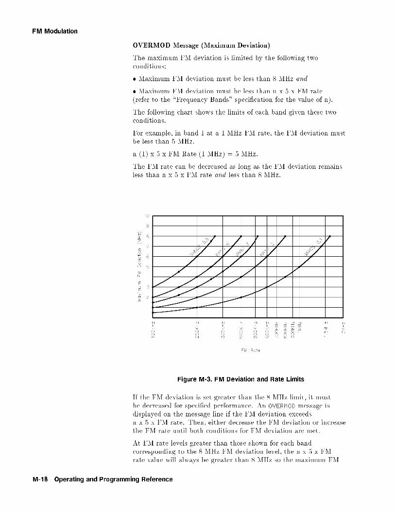
FM Modulation
OVERMOD Message (Maximum Deviation)
The maximum FM deviation is limited by the following twoconditions:
� Maximum FM deviation must be less than 8 MHz and
� Maximum FM deviation must be less than n x 5 x FM rate(refer to the \Frequency Bands" speci�cation for the value of n).
The following chart shows the limits of each band given these twoconditions.
For example, in band 1 at a 1 MHz FM rate, the FM deviation mustbe less than 5 MHz.
n (1) x 5 x FM Rate (1 MHz) = 5 MHz.
The FM rate can be decreased as long as the FM deviation remainsless than n x 5 x FM rate and less than 8 MHz.
Figure M-3. FM Deviation and Rate Limits
If the FM deviation is set greater than the 8 MHz limit, it mustbe decreased for speci�ed performance. An OVERMOD message isdisplayed on the message line if the FM deviation exceedsn x 5 x FM rate. Then, either decrease the FM deviation or increasethe FM rate until both conditions for FM deviation are met.
At FM rate levels greater than those shown for each bandcorresponding to the 8 MHz FM deviation level, the n x 5 x FMrate value will always be greater than 8 MHz so the maximum FM
M-18 Operating and Programming Reference

Pulse Modulation
deviation is no longer limited by the FM rate, only by the maximumlimit of 8 MHz.
Pulse Modulation Pulse modulation can be accepted from an external source at thePULSE connector or can be internally generated. The damage levelsof the PULSE input are +10 and �5 V DC. The input impedance is50 . A function generator must be capable of driving TTL levelsinto a 50 load. With no input signal, the pulse input is held low,so activating pulse with no input causes RF output to shut o�.
The swept signal generator can also produce a 27.778 kHz squarewave for use in Agilent scalar network analyzers. Swept signalgenerators with Option 002 internally generate a synthesized pulse.The swept signal generator provides internal pulse modulation withpulse widths adjustable with 1 �s resolution (adjustable with 25 nsresolution with Option 002).
Leveling
Pulse leveling performance depends on the accuracy of the diodedetector which measures the RF amplitude. The ALC block diagram,Figure M-4, shows the pulse modulation input signal to the sweptsignal generator which controls a pulse modulator. The pulse inputis represented by trace 1 in Figure M-5. The pulse modulator iseither full on or full o�. The amplitude, when the pulsed RF is on,is controlled by the linear modulator used for CW leveling and AM.Trace 2 is the resultant RF pulse, which is the RF output. This pulseis detected by the diode detector. It trails the pulse input because ofpropagation delays in the pulse modulator and its drive circuits.
The output of the detector is ampli�ed by a logarithmic ampli�er(log amp).
Trace 3 is the output of the log amp. Note that this signal isdelayed from the RF output signal and that the rise time is slower.This is a result of the bandwidth of the detector and the log amp.The amplitude of trace 3 is summed with the reference signalfrom the level DAC and the di�erence (error) signal drives anintegrate{and{hold circuit. The integrator output drives the RFoutput power level via the linear modulator. When the sum of thedetected and reference signals is 0 volts, the output of the integratoris held at a constant level and the RF output is leveled.
Trace 4 is the delayed signal from the pulse input which controls theswitch in the integrate{and{hold circuit. Trace 4 is timed to coincidewith trace 3. Since the integrate{and{hold switch is closed only whentrace 3 is high, the integrator responds to correct the power levelonly when the RF power is on.
Operating and Programming Reference M-19
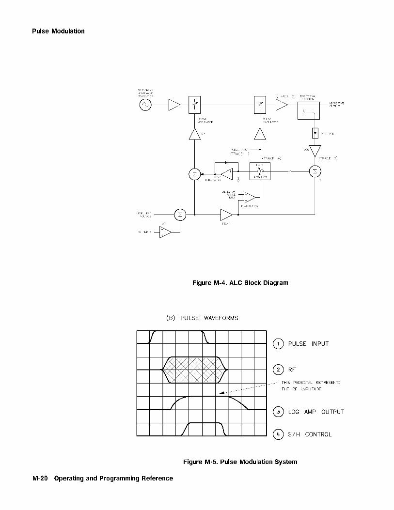
Pulse Modulation
Figure M-4. ALC Block Diagram
Figure M-5. Pulse Modulation System
M-20 Operating and Programming Reference
Pulse Modulation
Leveling Narrow Pulses
For narrow pulses of less than 1 �s width, either use search levelingmode or use unleveled operation. (If you do not, you will see theoutput level continue to rise as the swept signal generator tries tocorrect for the o� portion of the cycle.)
In search leveling mode, the RF amplitude is set with pulsemodulation o� and the ALC loop closed. Then the loop integratoroutput is measured. Next, the integrator is disconnected and themodulator is driven directly with a DC voltage which has been set tothe value that was provided by the loop integrator. Any AM signalpresent is added to this DC voltage. This procedure is automaticwith search leveling mode engaged. The level setting procedure isautomatically repeated whenever the carrier frequency or power levelis changed and takes approximately 250 ms. This procedure shouldalso be repeated periodically to correct for the e�ects of temperaturedrift.
Unleveled operation can be used for very narrow pulses by openingthe ALC loop (see \Leveling Mode ALCo�"). The power level is setin CW operation, with pulse modulation o�, using an external powermeter. With Option 006, pulses as narrow as 20 ns can be producedin this mode. Changes due to temperature drift can be expected inthis mode also.
Pulse Envelope
The best pulse envelopes are obtained with the peak RF function(see \Peak RF Always"). This feature aligns the output �lter sothat its passband is centered on the RF output. The pulse envelopechanges with frequency and changes slightly with power level. Sweptsignal generators with Option 006 pulse capability vary little withfrequency.
The pulse envelope produced by the swept signal generator has �niterise time and overshoot. Below 2.0 GHz, the rise time and overshootare essentially independent of frequency, but above 2.0 GHz, in sweptsignal generators without Option 006, they are strongly in uenced bythe passband shape and centering of the tracking YIG �lter.
Source Match
The best source match is obtained at the swept signal generator'soperating frequency. In addition, swept signal generators with certainRF components at the output provide improved broadband sourcematch. These include swept signal generators with Option 006, withhigh power output (Agilent 83623B and Agilent 83624B), or with theOption 001 step attenuator set to �10 dB.
Performance can be improved by padding between the re ections. Atthe source, for output power above �10 dBm, setting the levelingmode to normal results in 0 dB attenuation. If enough power isavailable, uncoupled operation can be used to improve the swept
Operating and Programming Reference M-21

Pulse Modulation
signal generator's source match by inserting 10 dB attenuation andusing a 10 dB higher ALC level.
Video Feedthrough
Video feedthrough is a video signal at the modulation rate that issuperimposed on the RF envelope (see Figure M-6). If large enough,video feedthrough can disturb mixer balance, ampli�er bias, crystaldetector output, etc. Because it is low frequency energy, it candisturb systems that are not intended to deal with it, especiallydemodulation systems. High band (>2.0 GHz) employs a trackingYIG �lter that essentially eliminates video feedthrough except inOption 006 (because the pulse modulator is after the YIG �lter).Attempts to measure high band video feedthrough can turn out tobe measurements of ground currents in coaxial cables. Low band(<2.0 GHz) employs a low-level mixer followed by a high gainampli�er. At high power levels (� �10 dBm), the bias levels in theampli�er shift slightly as the RF is turned on or o�. The slew of thebias from one level to another couples to the output and producesthe video feedthrough waveform. At low ALC levels (�10 dBm),another mechanism dominates. Mixer imbalance produces DC at theoutput of the mixer, and its magnitude varies with RF amplitude andmodulator state. This shifting DC level couples through the ampli�eras video feedthrough spikes. In percentage terms, this mechanismgets worse at low levels.
Figure M-6. Video Feedthrough
Slow Rise Time Pulse Modulation for Scalar Network Analyzers
For use with HP/Agilent scalar analyzers, the swept signal generatoro�ers a scalar pulse modulation mode that provides approximately 2�s rise and fall times. An internal oscillator provides the 27.778 kHzsquare wave with no external connections necessary. The slowwaveform reduces the spectral width of the output, improvingmeasurements made on �lters with steep skirts. A slow pulse risetime (approximately 2 �s) is available for externally generated pulseinputs as well.
M-22 Operating and Programming Reference

NNNNNNNNNNNNNNNNNNNNNNNNNNNNNNNNModule Menu
aaaaaaaaaaaaaaaaaaaaaaaaaaaaaaaaaaaaaaaaaaaaaaModule Menu
Function Group �ALC�
Menu Map 1
Description This softkey accesses the source module selection softkeys.Millimeter-wave source modules can be connected to the swept signalgenerator source module interface connectors (there is one eachon the front and rear panels). These softkeys give you the optionof letting the swept signal generator automatically look at bothconnectors for source modules or telling the swept signal generator tolook only at the front or at the rear connector. You can also turn o�module sensing completely.NNNNNNNNNNNNNNNNNNNNNNNNNNNNNNNNNNNNNNNNNNNNNNNNNNNNNNNNModule Select AUTO Sets the swept signal generator to
automatic selection of the sourcemodule.(Selects the front connector if sourcemodules are present at both front andrear connectors.) This is the defaultafter preset.NNNNNNNNNNNNNNNNNNNNNNNNNNNNNNNNNNNNNNNNNNNNNNNNNNNNNNNNNNN
Module Select Front Sets the swept signal generator to selectthe source module connected to the frontpanel source module interface connector.NNNNNNNNNNNNNNNNNNNNNNNNNNNNNNNNNNNNNNNNNNNNNNNNNNNNNNNN
Module Select Rear Sets the swept signal generator to selectthe source module connected to the rearpanel source module interface connector.NNNNNNNNNNNNNNNNNNNNNNNNNNNNNNNNNNNNNNNNNNNNNNNNNNNNNNNN
Module Select None Disables source module sensing.
Programming Codes SCPI: NONEAnalyzer: NONE
See Also Softkeys listed above.
Operating and Programming Reference M-23

aaaaaaaaaaaaaaaaaaaaaaaaaaaaaaaaaaaaaaaaaaaaaaaaaaaaaaaaaaaaaaaaaaaaaaaaaModule Select AUTO
Function Group POWER and FREQUENCY
Menu Map 2 and 5
Description This command sets the automatic selection of the millimeter sourcemodule interface connector. The swept signal generator looks at bothfront and rear connectors and determines the type of source module(if any) connected. If a source module is present at both connectors,the swept signal generator selects the front connector as the activeone. After selecting the interface the instrument frequency limitsand multiplier are altered accordingly. However, the leveling point isnot changed. See
NNNNNNNNNNNNNNNNNNNNNNNNNNNNNNNNNNNNNNNNNNNNNNNNNNNNNNNNNNNNNNNNNLeveling Point Module to set the swept signal
generator to level at the output of the source module.
An asterisk next to the key label indicates this feature is active. Thisfeature is the default after preset.
Programming Codes SCPI:
SYSTem:MMHead:SELect:AUTO ONjOFFj1j0SYSTem:MMHead:SELect:AUTO?
Analyzer: NONE
See AlsoNNNNNNNNNNNNNNNNNNNNNNNNNNNNNNNNNNNModule Menu
aaaaaaaaaaaaaaaaaaaaaaaaaaaaaaaaaaaaaaaaaaaaaaaaaaaaaaaaaaaaaaaaaaaaaaaaaaaaaModule Select Front
Function Group POWER and FREQUENCY
Menu Map 2 and 5
Description This command causes the swept signal generator to examine onlythe front panel source module interface connector to determinethe type of source module (if any) connected. The instrumentfrequency limits and multiplier are altered according to the sourcemodule connected. However, the leveling point is not changed. SeeNNNNNNNNNNNNNNNNNNNNNNNNNNNNNNNNNNNNNNNNNNNNNNNNNNNNNNNNNNNNNNNNNLeveling Point Module to set the swept signal generator to levelat the output of the source module.
An asterisk next to the key label indicates this feature is active.
M-24 Operating and Programming Reference

NNNNNNNNNNNNNNNNNNNNNNNNNNNNNNNNNNNNNNNNNNNNNNNNNNNModule Select None
Programming Codes SCPI:
SYSTem:MMHead:SELect FRONtjREARjNONESYSTem:MMHead:SELect?
Analyzer: NONE
See AlsoNNNNNNNNNNNNNNNNNNNNNNNNNNNNNNNNNNNModule Menu
aaaaaaaaaaaaaaaaaaaaaaaaaaaaaaaaaaaaaaaaaaaaaaaaaaaaaaaaaaaaaaaaaaaaaaaaaModule Select None
Function Group POWER and FREQUENCY
Menu Map 2 and 5
Description This command disables millimeter source module sensing. The sweptsignal generator will not alter its frequency limits and multiplier evenif a source module is connected to either source module interfaceconnector.
An asterisk next to the key label indicates this feature is active.
Programming Codes SCPI:
SYSTem:MMHead:SELect FRONtjREARjNONESYSTem:MMHead:SELect?
Analyzer: NONE
See AlsoNNNNNNNNNNNNNNNNNNNNNNNNNNNNNNNNNNNModule Menu
Operating and Programming Reference M-25

aaaaaaaaaaaaaaaaaaaaaaaaaaaaaaaaaaaaaaaaaaaaaaaaaaaaaaaaaaaaaaaaaaaaaaaaaModule Select Rear
Function Group POWER and FREQUENCY
Menu Map 2 and 5
Description This command causes the swept signal generator to examine onlythe rear panel source module interface connector to determinethe type of source module (if any) connected. The instrumentfrequency limits and multiplier are altered according to the sourcemodule connected. However, the leveling point is not changed. SeeNNNNNNNNNNNNNNNNNNNNNNNNNNNNNNNNNNNNNNNNNNNNNNNNNNNNNNNNNNNNNNNNNLeveling Point Module to set the swept signal generator to levelat the output of the source module.
An asterisk next to the key label indicates this feature is active.
Programming Codes SCPI:
SYSTem:MMHead:SELect FRONtjREARjNONESYSTem:MMHead:SELect?
Analyzer: NONE
See AlsoNNNNNNNNNNNNNNNNNNNNNNNNNNNNNNNNNNNModule Menu
aaaaaaaaaaaaaaaaaaaaaaaaaaaaaaaaaaaaaaaaaaaaaaaaaaMonitor Menu
Function Group �MOD�
Menu Map 4
Description This softkey (Option 002 only) accesses the menu which allows youto output internally-generated AM and FM waveforms to the rearpanel AM/FM OUTPUT connector. It also accesses the softkeyswhich allow you to display the AM depth and FM deviation of themodulation waveforms.NNNNNNNNNNNNNNNNNNNNNNNNNNNNNNNNNNNNNNNNNNNNNNNNNNModOut On/Off AM Outputs the AM waveform to the AM/FM
OUTPUT connector.NNNNNNNNNNNNNNNNNNNNNNNNNNNNNNNNNNNNNNNNNNNNNNNNNNModOut On/Off FM Outputs the FM waveform to the AM/FM
OUTPUT connector.NNNNNNNNNNNNNNNNNNNNNNNNNNNNNNNNNNNNNNNNNNNNNNNMeter On/Off AM Displays the AM depth of the modulating
signal.
M-26 Operating and Programming Reference
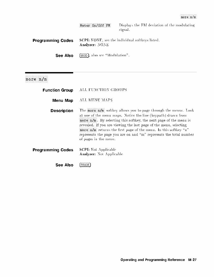
NNNNNNNNNNNNNNNNNNNNNNNNmore n/m
NNNNNNNNNNNNNNNNNNNNNNNNNNNNNNNNNNNNNNNNNNNNNNNMeter On/Off FM Displays the FM deviation of the modulating
signal.
Programming Codes SCPI: NONE, see the individual softkeys listed.Analyzer: NONE
See Also �MOD�, also see \Modulation".
aaaaaaaaaaaaaaaaaaaaaaaaaaaaaaaaaamore n/m
Function Group ALL FUNCTION GROUPS
Menu Map ALL MENU MAPS
Description TheNNNNNNNNNNNNNNNNNNNNNNNNNNmore n/m softkey allows you to page through the menus. Look
at one of the menu maps. Notice the line (keypath) drawn fromNNNNNNNNNNNNNNNNNNNNNNNNNNmore n/m . By selecting this softkey, the next page of the menu isrevealed. If you are viewing the last page of the menu, selectingNNNNNNNNNNNNNNNNNNNNNNNNNNmore n/m returns the �rst page of the menu. In this softkey \n"represents the page you are on and \m" represents the total numberof pages in the menu.
Programming Codes SCPI: Not ApplicableAnalyzer: Not Applicable
See Also �PRIOR�
Operating and Programming Reference M-27

aaaaaaaaaaaaaaaaaaaaaaaaaaaaaaaaaaaaaaaaaaaaaaaaaaaaaaMtr Meas Menu
Function Group POWER
Menu Map 5
Description This softkey accesses the meter measure softkeys.NNNNNNNNNNNNNNNNNNNNNNNNNNNNNNNNNNNNNNNNNMeas Corr All Measures atness correction values for all
frequency points in the atness correctionarray.NNNNNNNNNNNNNNNNNNNNNNNNNNNNNNNNNNNNNNNNNNNNNNNNNNNNN
Meas Corr Current Measures a atness correction value for thefrequency point currently in the active line ofthe atness correction array.NNNNNNNNNNNNNNNNNNNNNNNNNNNNNNNNNNNNNNNNNNNNNNN
Meas Corr Undef Measures atness correction values for allfrequency points in the atness correctionarray that have no correction values assigned.
The meter measure function uses an external HP/Agilent 437B powermeter to automatically measure and store power correction values forthe frequency points requested.
Programming Codes SCPI: NONE, seeNNNNNNNNNNNNNNNNNNNNNNNNNNNNNNNNNNNNNNFltness Menu
Analyzer: NONE
See AlsoNNNNNNNNNNNNNNNNNNNNNNNNNNNNNNNNNNNNNNNNNFlatness Menu
\Creating and Applying the User Flatness Correction Array" inChapter 1
M-28 Operating and Programming Reference
P
aaaaaaaaaaaaaaaaaaaaaaaaaaaaaaaaaaaaaaaaaaaaaaaaaaaaaaaaaPeak RF Always
Function Group POWER, USER CAL
Menu Map 5, 9
Description This softkey appears in two locations: the POWERNNNNNNNNNNNNNNNNNNNNNNNNNNNNNNNNNNNNNNNNNTracking Menu
and the USER CALNNNNNNNNNNNNNNNNNNNNNNNNNNNNNNNNNNNNNNNNNTracking Menu . The operation is the same in
both locations.
This softkey causes the swept signal generator, when in CW ormanual-sweep output mode, to align the output �lter (SYTM) sothat its passband is centered on the RF output. Peaking is used toobtain both the maximum available power and spectral purity, andthe best pulse, FM envelopes, at a given frequency. This peakingoccurs each time the frequency is changed, or every seven minutes.An asterisk next to the key label indicates this function is active.
Programming Codes SCPI: CALibration:PEAKing:AUTO ONjOFFj1j0Analyzer: RP1 function on, RP0 function o�.
See AlsoNNNNNNNNNNNNNNNNNNNNNNNNNNNNNNNNAuto Track ,
NNNNNNNNNNNNNNNNNNNNNNNNNNNNNNNNNNNNNNPeak RF Once ,
NNNNNNNNNNNNNNNNNNNNNNNNNNNNNNNNNNNNNNNNNTracking Menu
\Optimizing Swept Signal Generator Performance" in Chapter 1
Operating and Programming Reference P-1
aaaaaaaaaaaaaaaaaaaaaaaaaaaaaaaaaaaaaaaaaaaaaaaaaaPeak RF Once
Function Group POWER, USER CAL
Menu Map 5, 9
Description This softkey appears in two locations: the POWERNNNNNNNNNNNNNNNNNNNNNNNNNNNNNNNNNNNNNNNNNTracking Menu
and the USER CALNNNNNNNNNNNNNNNNNNNNNNNNNNNNNNNNNNNNNNNNNTracking Menu . The operation is the same in
both locations.
This softkey causes an instantaneous, one-time execution of thepeaking function when the swept signal generator is in the CW ormanual sweep mode. It aligns the output �lter (SYTM) so that itspassband is centered on the RF output.
Programming Codes SCPI: CALibration:PEAKing[:EXECute]Analyzer: SHAK
See AlsoNNNNNNNNNNNNNNNNNNNNNNNNNNNNNNNNNNNNNNNNNAuto Tracking ,
NNNNNNNNNNNNNNNNNNNNNNNNNNNNNNNNNNNNNNNNNNNNPeak RF Always ,
NNNNNNNNNNNNNNNNNNNNNNNNNNNNNNNNNNNNNNNNNTracking Menu
\Optimizing Swept Signal Generator Performance" in Chapter 1
�POWER LEVEL�
Function Group POWER
Menu Map NONE
Description This hardkey lets you control the output power level of the sweptsignal generator. The swept signal generator has di�erent powerleveling modes and leveling points, and as such, the �POWER LEVEL�key controls di�erent aspects of the power level (ALC) system.
The following is an explanation of power level operation in thedi�erent ALC system con�gurations.
In Normal, Internal, the �POWER LEVEL� key controls the outputpower level of the swept signal generator directly. The attenuator(if present) is controlled together with the complete range of the ALCsystem (+25 to �20 dBm).
P-2 Operating and Programming Reference

�POWER LEVEL�
When you press �POWER LEVEL�, the active entry area displays:--> POWER LEVEL: X.XX dBm,where X represents a numeric value. The data display area indicates:Power(dBm)
INT: X.XX.
In Normal, Uncoupled Attenuator, the �POWER LEVEL� key controlsthe Level DAC and Level Control Circuits (see Figure A-1)within the ALC level range (+25 to �20 dBm). The attenuator isuncoupled from the ALC system and is controlled separately with theNNNNNNNNNNNNNNNNNNNNNNNNNNNNNSet Atten key.
When you press �POWER LEVEL�, the active entry area displays:
--> ATTEN X dB, ALC: X.XX dBm,
where X represents a numeric value. The data display area indicates:
Power(dBm)
INT: X.XX .
In Normal, External Detector (ExtDet), the �POWER LEVEL� keycontrols the output power of the swept signal generator as comparedto the external detector feedback voltage. The attenuator(if present) is automatically uncoupled from the ALC system and the�POWER LEVEL� key controls the Level DAC and Level Control Circuits(see Figure A-1) within the ALC level range (+25 to �20 dBm).This mode of operation requires a feedback connection from anegative-output diode detector to the EXT ALC connector.
When you press �POWER LEVEL�, the active entry area displays:
--> ATTEN X dB, EXT POWER: X.XX dBm ,
where X represents a numeric value. The data display area indicates:
Power(dBm)
EXT: X.XX .
In Normal, Power Meter (PwrMtr), the �POWER LEVEL� key controlsthe output power of the swept signal generator as comparedto the feedback voltage of the power meter. The attenuator(if present) is automatically uncoupled from the ALC system andthe �POWER LEVEL� key controls the Level DAC and Level ControlCircuits (see Figure A-1) within a more restricted range of the ALClevel. Instead of the 45 dB range of the ALC in other modes, 12 dBis available in this mode, with the upper end of the range set by theNNNNNNNNNNNNNNNNNNNNNNNNNNNNNNNNNNNNNNNNNPwr Mtr Range softkey. This mode of operation requires a feedbackconnection from the recorder output of a power meter.
Operating and Programming Reference P-3

�POWER LEVEL�
When you press �POWER LEVEL�, the active entry area displays:
--> ATTEN X dB, POWER LEVEL: X.XX dBm ,
where X represents a numeric value. The data display area indicates:
Power(dBm)
MTR: X.XX .
In Normal, Module, the �POWER LEVEL� key controls the outputpower of the swept signal generator as compared to the feedbackvoltage from a millimeter-wave source module. The attenuator (ifpresent) is automatically uncoupled from the ALC system and the�POWER LEVEL� key controls the Level DAC and Level Control Circuits(see Figure A-1) within the ALC level range (+25 to �20 dBm). Thismode of operation requires a feedback connection from the moduleto the swept signal generator through the SOURCE MODULEINTERFACE.
When you press �POWER LEVEL�, the active entry area displays:
--> ATTEN X dB, MODULE LEVEL: X.XX dBm ,
where X represents a numeric value. The data display area indicates:
Power(dBm)
MDL: X.XX .
In ALCo� , there is no feedback voltage to level the power, so powerlevel is uncalibrated. A leveling point is not speci�ed in this mode.The �POWER LEVEL� key controls the linear modulator directly,from 0 to approximately �80 dB. The attenuator (if present) isautomatically uncoupled from the ALC system.
When you press �POWER LEVEL�, the active entry area displays:
--> ATTEN X dB, REFERENCE: X.XX dB ,
where X represents a numeric value. The data display area indicates:
Ref(dB)
OFF: X.XX
and the message line indicates: UNLVLED.
In Search, any of the leveling points can be speci�ed and used as thecomparison feedback voltage. Basically, this mode operates the sameas ALCo� after the searched-for power level is reached. The activeentry area displays di�erent information depending on the levelingpoint chosen.
P-4 Operating and Programming Reference
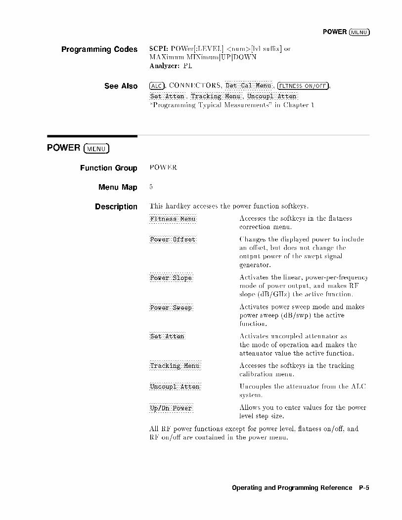
POWER �MENU�
Programming Codes SCPI: POWer[:LEVEL] <num>[lvl su�x] orMAXimumjMINimumjUPjDOWNAnalyzer: PL
See Also �ALC�, CONNECTORS,NNNNNNNNNNNNNNNNNNNNNNNNNNNNNNNNNNNNNNDet Cal Menu , �FLTNESS ON/OFF�,NNNNNNNNNNNNNNNNNNNNNNNNNNNNN
Set Atten ,NNNNNNNNNNNNNNNNNNNNNNNNNNNNNNNNNNNNNNNNNTracking Menu ,
NNNNNNNNNNNNNNNNNNNNNNNNNNNNNNNNNNNNNNNNNUncoupl Atten
\Programming Typical Measurements" in Chapter 1
POWER �MENU�
Function Group POWER
Menu Map 5
Description This hardkey accesses the power function softkeys.NNNNNNNNNNNNNNNNNNNNNNNNNNNNNNNNNNNNNNFltness Menu Accesses the softkeys in the atness
correction menu.NNNNNNNNNNNNNNNNNNNNNNNNNNNNNNNNNNNNNNPower Offset Changes the displayed power to include
an o�set, but does not change theoutput power of the swept signalgenerator.NNNNNNNNNNNNNNNNNNNNNNNNNNNNNNNNNNN
Power Slope Activates the linear, power-per-frequencymode of power output, and makes RFslope (dB/GHz) the active function.
NNNNNNNNNNNNNNNNNNNNNNNNNNNNNNNNNNNPower Sweep Activates power sweep mode and makes
power sweep (dB/swp) the activefunction.NNNNNNNNNNNNNNNNNNNNNNNNNNNNN
Set Atten Activates uncoupled attenuator asthe mode of operation and makes theattenuator value the active function.NNNNNNNNNNNNNNNNNNNNNNNNNNNNNNNNNNNNNNNNN
Tracking Menu Accesses the softkeys in the trackingcalibration menu.NNNNNNNNNNNNNNNNNNNNNNNNNNNNNNNNNNNNNNNNN
Uncoupl Atten Uncouples the attenuator from the ALCsystem.NNNNNNNNNNNNNNNNNNNNNNNNNNNNNNNNNNN
Up/Dn Power Allows you to enter values for the powerlevel step size.
All RF power functions except for power level, atness on/o�, andRF on/o� are contained in the power menu.
Operating and Programming Reference P-5
POWER �MENU�
Programming Codes SCPI: NONEAnalyzer: NONE
See Also Softkeys listed previously under this menu key, �ALC�,�FLTNESS ON/OFF�, �POWER LEVEL�, and �RF ON/OFF�.\Introducing the 8360 B-Series Swept Signal Generators" inChapter 1\Getting Started Advanced" in Chapter 1\Programming Typical Measurements" in Chapter 1
aaaaaaaaaaaaaaaaaaaaaaaaaaaaaaaaaaaaaaaaaaaaaaaaaaPower Offset
Function Group POWER
Menu Map 5
Description This softkey changes the mapping of absolute power parameterson input to the swept signal generator. It does not change the RFoutput produced by the swept signal generator. The equation used todetermine the displayed value is:
Entered or Displayed Power = Hardware Power (ALC) + Active O�set
Programming Codes SCPI:
POWer:OFFset:STATe ONjOFFj1j0POWer:OFFset <num>[DB]jMAXimumjMINimumjUPjDOWN
Analyzer: NONE
See Also �POWER LEVEL� and POWER �MENU�.
P-6 Operating and Programming Reference
NNNNNNNNNNNNNNNNNNNNNNNNNNNNNNNNPower Slope
aaaaaaaaaaaaaaaaaaaaaaaaaaaaaaaaaaaaaaaaaaaaaaPower Slope
Function Group POWER
Menu Map 5
Description This softkey lets you compensate for system, cable, and waveguidevariations due to changes in frequency, by linearly increasing ordecreasing power output as the frequency increases. RF slope valuesmay range from �2.50 to +2.50 dB per GHz. The power at thebeginning of the sweep equals the current power level. An asterisknext to the key label indicates that this feature is active.
Programming Codes SCPI:
POWer:SLOPe:STATe ONjOFFj1j0POWer:SLOPe <num>[DB]jMAXimumjMINimumjUPjDOWN
Analyzer: SL1 function on, SL0 function o�. Note that because SLfunctions in the fundamental units of dB/Hz, you program the SLcode SLmdt, where m is 1 (on) or 0 (o�); d is the numerical valuein dB/Hz, and t is either \DB" or the ASCII LF terminator. Forexample, for a slope of 1.5 dB/GHz use this procedure:
1. 1.5 dB/GHz = 1.5 dB/1,000,000,000 Hz
2. 1.5 dB/1E9 Hz = 1.5E-9 dB/Hz
3. The programming code is \SL11.5E-9 DB"
See Also �POWER LEVEL�,NNNNNNNNNNNNNNNNNNNNNNNNNNNNNNNNNNNPower Sweep
\Power Sweep and Power Slope Operation" in Chapter 1
Operating and Programming Reference P-7

aaaaaaaaaaaaaaaaaaaaaaaaaaaaaaaaaaaaaaaaaaaaaaPower Sweep
Function Group POWER
Menu Map 5
Description This softkey enables the power sweep function. RF output powercan be swept both positively and negatively over a selected range.The level of the power sweep starting point is the power levelprogrammed. Power sweep widths can be 45 dB wide in eitherdirection. However, the settable power sweep range is dependent onthe ALC level set. An asterisk next to the key label indicates thatthis feature is active.
Programming Codes SCPI:
POWer:MODE SWEepjFIXedPOWer:STARt <num>[level su�x]jMAXimumjMINimumPOWer:SPAN <num>[level su�x]jMAXimumjMINimum
Analyzer: PS1 function on, PS0 function o�.
See Also �POWER LEVEL�,NNNNNNNNNNNNNNNNNNNNNNNNNNNNNNNNNNNPower Slope
\Power Sweep and Power Slope Operation" in Chapter 1
P-8 Operating and Programming Reference
�PRESET�
�PRESET�
Function Group INSTRUMENT STATE
Menu Map NONE
Description This hardkey (green) causes the swept signal generator to perform ashort version of self-test, and initializes the swept signal generator toa standard starting con�guration. Two states can be de�ned for thestandard con�guration: Factory or User.
Press �PRESET� at any time to test the swept signal generator andrestore to a standard con�guration. If the red LED adjacent to THE�PRESET� KEY (labeled INSTR CHECK) stays on after preset, theswept signal generator failed self-test; refer to Agilent Technologies8360 B-Series Swept Signal Generator/8360 L-Series Swept CWGenerator Troubleshooting Guide.
Cycling power with the POWER switch does not have the samee�ect as presetting the swept signal generator. Cycling power causesthe swept signal generator to display the programming language, theGPIB address, and the �rmware revision date. After the swept signalgenerator displays this data, it restores its con�guration to the statebefore power was turned o�.
Programming Codes SCPI: SYSTem:PRESet[:EXECute]Analyzer: IP
See AlsoNNNNNNNNNNNNNNNNNNNNNNNNNNNNNNNNNNNNNNNNNNNNNNNNNNNNNNNNNNNPreset Mode Factory ,
NNNNNNNNNNNNNNNNNNNNNNNNNNNNNNNNNNNNNNNNNNNNNNNNNNPreset Mode User
\Changing the Preset Parameters" in Chapter 1\Programming Typical Measurements" in Chapter 1
Operating and Programming Reference P-9

xFxFxFxFxFxFxFxFxFxFxFxFxFxFxFxFxFxFxFxFxFxFxFxFxFxFxFxFxFxFxFxFxFxFxFxFxFxFxFxFxFxFxFxFxFxF
Preset Mode
Factory
Function Group SYSTEM
Menu Map 8
Description This softkey sets the standard starting con�guration of the sweptsignal generator when the �PRESET� key is pressed, as set by themanufacturer. An asterisk next to the key label indicates that thisfeature is active. The following is a description of the con�guration.
Start sweep at the minimum speci�ed frequency.
Stop sweep at the maximum speci�ed frequency.
Power level set at 0 dBm.
Sweep time set to auto.
CONT sweep.
Sweep mode ramp.
ALC leveling point internal.
ALC leveling mode normal.
Markers set to activate at the center frequency of the sweep.
All function values stored in memory registers 1 through 9 remainin their previous states.
The checksum of the calibration data is calculated, and if an erroris detected, the calibration data in protected memory is used. Ifthe checksum of the protected data is not correct, then defaultvalues are used an error message (EEROM FAILED, LOST CAL)is displayed.
Programming Codes SCPI: SYSTem:PRESet:TYPE FACToryAnalyzer: IP, which is the same as �PRESET�.
See Also �PRESET�,NNNNNNNNNNNNNNNNNNNNNNNNNNNNNNNNNNNNNNNNNNNNNNNNNNPreset Mode User
\Changing the Preset Parameters" in Chapter 1
P-10 Operating and Programming Reference

NNNNNNNNNNNNNNNNNNNNNNNNNNNNNNNNNNNPrinter Adrs
aaaaaaaaaaaaaaaaaaaaaaaaaaaaaaaaaaaaaaaaaaaaaaaaaaaaaaaaaaaaaaaaaPreset Mode User
Function Group SYSTEM
Menu Map 8
Description This softkey sets the standard starting con�guration of theswept signal generator when the �PRESET� key is pressed, as setby the user. You can de�ne any starting conditions: Set up theswept signal generator with the conditions you want, then selectNNNNNNNNNNNNNNNNNNNNNNNNNNNNNNNNNNNNNNNNNNNNNNNNNNPreset Mode User . Now whenever you press �PRESET�, the sweptsignal generator returns to the con�guration you set. If preset modeuser is set, when you press �PRESET�, the swept signal generatordisplays the following:
*** USER DEFINED PRESET RECALLED ***
You can still do a factory preset. When the user preset modeis active, the softkey
NNNNNNNNNNNNNNNNNNNNNNNNNNNNNNNNNNNNNNNNNNNNFactory Preset appears when you press
�PRESET�. An asterisk next to the key label indicates that this featureis active.
Programming Codes SCPI:SYSTem:PRESet TYPE USERAnalyzer: NONE
See Also �PRESET�,NNNNNNNNNNNNNNNNNNNNNNNNNNNNNNNNNNNNNNNNNNNNNNNNNNNNNNNNNNNPreset Mode Factory ,
NNNNNNNNNNNNNNNNNNNNNNNNNNNNNNNNNNNNNNNNNNNNNNNNNNSave User Preset
\Changing the Preset Parameters" in Chapter 1
aaaaaaaaaaaaaaaaaaaaaaaaaaaaaaaaaaaaaaaaaaaaaaaaaaPrinter Adrs
Function Group SYSTEM
Menu Map 8
Description This softkey lets the swept signal generator recognize a printeraddress between 0 and 30. The swept signal generator can act as acontroller for a printer during self-test, if the log-to-a-printer featureis initiated.
Programming Codes SCPI: DIAGnostic:INSTrument:PRINTer:ADDRess <num>Analyzer: NONE
See AlsoNNNNNNNNNNNNNNNNNNNNNNNNNNNNNAdrs Menu ,
NNNNNNNNNNNNNNNNNNNNNNNNNNNNNNNNNNNNNNNNNNNNNNNSelftest (Full)
Operating and Programming Reference P-11

�PRIOR�
Function Group MENU SELECT
Menu Map NONE
Description This hardkey lets you view previous menus. All menus visitedfrom the last preset are remembered and displayed in a\last-visited-�rst-seen" order. Refer to Figure P-1, and follow thearrow paths as indicated.
Figure P-1. How �PRIOR� Works
The sequence of keystrokes that created the movement shown inFigure P-1 is:
1. FREQUENCY �MENU�2.
NNNNNNNNNNNNNNNNNNNNNNNNNNmore 1/2
3.NNNNNNNNNNNNNNNNNNNNNNNNNNNNNList Menu
4.NNNNNNNNNNNNNNNNNNNNNNNNNNNNNNNNNNNDelete Menu
5. �PRIOR�6. �PRIOR�7. �PRIOR�
P-12 Operating and Programming Reference
NNNNNNNNNNNNNNNNNNNNNNNNNNNNNNNNNNNNNNNNNNNNNNNNNNNNNNNNNNNNNNNNNNNNNNProgramming Language CIIL
Programming Codes SCPI: NONEAnalyzer: NONE
See AlsoNNNNNNNNNNNNNNNNNNNNNNNNNNmore n/m
xFxFxFxFxFxFxFxFxFxFxFxFxFxFxFxFxFxFxFxFxFxFxFxFxFxFxFxFxFxFxFxFxFxFxFxFxFxFxFxFxFxFxFxFxFxFxFxFxFxFxFxFxFxFxFxFxFxFxFxFxFxFxFxFxFxFxFxFxF
Programming
Language Analyzr
Function Group SYSTEM
Menu Map 8
Description This softkey lets you select Analyzer Language as the swept signalgenerator's interface language. This language uses HP/Agilent8340/8341 mnemonics and provides Agilent network analyzercompatibility. Any commands issued within 100 ms of a change inlanguage may be ignored or lost. An asterisk next to the key labelindicates that this feature is active.
Programming Codes SCPI: SYSTem:LANGuage COMPatibleAnalyzer: NONE
See AlsoNNNNNNNNNNNNNNNNNNNNNNNNNNNNNAdrs Menu , ANALYZER STATUS REGISTER\Getting Started Programming" in Chapter 1Chapter 3
xFxFxFxFxFxFxFxFxFxFxFxFxFxFxFxFxFxFxFxFxFxFxFxFxFxFxFxFxFxFxFxFxFxFxFxFxFxFxFxFxFxFxFxFxFxFxFxFxFxFxFxFxFxFxFxFxF
Programming
Language CIIL
Function Group SYSTEM
Menu Map 8
Operating and Programming Reference P-13
NNNNNNNNNNNNNNNNNNNNNNNNNNNNNNNNNNNNNNNNNNNNNNNNNNNNNNNNNNNNNNNNNNNNNNProgramming Language CIIL
Description This softkey lets you select CIIL as the swept signal generator'sexternal interface language. The use of this language requires theM.A.T.E. option (Option 700) to be installed. Any commands issuedwithin 100 ms of a change in language may be ignored or lost. Anasterisk next to the key label indicates that this feature is active.
Programming Codes SCPI: SYSTem:LANGuage CIILAnalyzer: CIIL
See AlsoNNNNNNNNNNNNNNNNNNNNNNNNNNNNNAdrs Menu
The M.A.T.E. option (Option 700) is documented in a separatemanual supplement called, Agilent Technologies 8360 SeriesSynthesized Sweepers Option 700 Manual Supplement .
xFxFxFxFxFxFxFxFxFxFxFxFxFxFxFxFxFxFxFxFxFxFxFxFxFxFxFxFxFxFxFxFxFxFxFxFxFxFxFxFxFxFxFxFxFxFxFxFxFxFxFxFxFxFxFxFxF
Programming
Language SCPI
Function Group SYSTEM
Menu Map 8
Description Standard Commands for Programmable Instruments (SCPI)is the instrument control programming language adopted byAgilent Technologies. SCPI provides commands that are commonfrom one Agilent Technologies product to another, eliminating\device speci�c" commands.
This softkey lets you select SCPI as the swept signal generator'sexternal interface language. This is the default language set at thefactory. Any commands issued within 100 ms of a change in languagemay be ignored or lost. An asterisk next to the key label indicatesthat this feature is active.
Programming Codes SCPI: SYSTem:LANGuage SCPIAnalyzer: SYST or SCPI
See AlsoNNNNNNNNNNNNNNNNNNNNNNNNNNNNNAdrs Menu , SCPI COMMAND SUMMARY, SCPI STATUSREGISTER STRUCTURE\Getting Started Programming" in Chapter 1\Programming Typical Measurements" in Chapter 1
P-14 Operating and Programming Reference
NNNNNNNNNNNNNNNNNNNNNNNNNNNNNNNNNNNPt Trig Menu
aaaaaaaaaaaaaaaaaaaaaaaaaaaaaaaaaaaaaaaaaaaaaaaaaaPt Trig Menu
Function Group FREQUENCY
Menu Map 2
Description This softkey accesses the list mode point trigger softkeys.NNNNNNNNNNNNNNNNNNNNNNNNNNNNNNNNNNNNNNNNNNNNNNNNNNNNNNNNNNNNNNNNNNNNList Mode Pt Trig Auto Automatically steps the swept
signal generator to next point in thefrequency list.NNNNNNNNNNNNNNNNNNNNNNNNNNNNNNNNNNNNNNNNNNNNNNNNNNNNNNNNNNNNNNNNN
List Mode Pt Trig Bus Steps the swept signal generator tothe next point in the frequency listwhen an GPIB trigger is received.NNNNNNNNNNNNNNNNNNNNNNNNNNNNNNNNNNNNNNNNNNNNNNNNNNNNNNNNNNNNNNNNN
List Mode Pt Trig Ext Steps the swept signal generator tothe next point in the frequency listwhen an external hardware triggeris received.
Programming Codes SCPI: NONEAnalyzer: NONE
See Also Softkeys listed above,NNNNNNNNNNNNNNNNNNNNNNNNNNNNNList Menu
Operating and Programming Reference P-15

aaaaaaaaaaaaaaaaaaaaaaaaaaaaaaaaaaaaaaaaaaaaaaaaaaaaaaaaaaaaaaaaaaaaaaaaaPulse Delay Normal
Function Group �MOD�
Menu Map 4
Description This softkey (Option 002 only) lets you set a value for the internalpulse generator's pulse delay. The output pulse is delayed fromthe leading edge of the PULSE SYNC OUT signal. The range ofacceptable values is from 0 to a maximum of 25 ns less than theperiod. The factory preset default is 0 ns. Use the numeric entrykeys, arrow keys, or rotary knob to change the value. When thisfeature is active, its current value is displayed in the active entryarea.
Programming Codes SCPI: PULM:INTernal:DELay <num>[time su�x]jMAXimumjMINimum
Analyzer: NONE
See Also �MOD�, also see \Pulse" and \Modulation".
aaaaaaaaaaaaaaaaaaaaaaaaaaaaaaaaaaaaaaaaaaaaaaaaaaaaaaaaaaaaaaaaaaaaaaaaaPulse Delay Trig'd
Function Group �MOD�
Menu Map 4
Description This softkey (Option 002 only) lets you set a value for the internalpulse generator's pulse delay. The output pulse is delayed from theleading edge of the PULSE input signal. The range of acceptablevalues is from 225 ns to 419 ms. The factory preset default is 225 ns.Use the numeric entry keys, arrow keys, or rotary knob to change thevalue. When this feature is active, its current value is displayed inthe active entry area.
Programming Codes SCPI: PULM:EXTernal:DELay <num>[time su�x]jMAXimumjMINimum
Analyzer: NONE
See Also �MOD�, also see \Pulse" and \Modulation".
P-16 Operating and Programming Reference

NNNNNNNNNNNNNNNNNNNNNNNNNNNNNPulse Menu
aaaaaaaaaaaaaaaaaaaaaaaaaaaaaaaaaaaaaaaaaaPulse Menu
Function Group �MOD�
Menu Map 4
Description This description is for theNNNNNNNNNNNNNNNNNNNNNNNNNNNNNNNNPulse Menu softkey for swept signal
generators without Option 002. For the Option 002NNNNNNNNNNNNNNNNNNNNNNNNNNNNNNNNPulse Menu
softkey go to the \Pulse Menu" heading that follows this one.
This softkey reveals the pulse parameter softkeys.NNNNNNNNNNNNNNNNNNNNNNNNNNNNNNNNNNNNNNPulse Period Sets the internal pulse generator's
pulse period.NNNNNNNNNNNNNNNNNNNNNNNNNNNNNNNNPulse Rate Sets the internal pulse generator's
pulse repetition rate.NNNNNNNNNNNNNNNNNNNNNNNNNNNNNNNNNNNNNNNNNNNNNNNNNNNNNNNNNNNNNNPulse Rise Time Auto Applies the appropriate �lter
(fast, slow) to both internal andexternal pulse waveforms.NNNNNNNNNNNNNNNNNNNNNNNNNNNNNNNNNNNNNNNNNNNNNNNNNNNNNNNNNNNNNN
Pulse Rise Time Fast Applies a fast rise pulse �lter toboth internal and external pulsewaveforms.NNNNNNNNNNNNNNNNNNNNNNNNNNNNNNNNNNNNNNNNNNNNNNNNNNNNNNNNNNNNNN
Pulse Rise Time Slow Applies a slow rise pulse �lter toboth internal and external pulsewaveforms.NNNNNNNNNNNNNNNNNNNNNNNNNNNNNNNNNNN
Pulse Width Sets the internal pulse generator'spulse width.
See Also Softkeys listed above, �ALC�, �MOD�
Operating and Programming Reference P-17
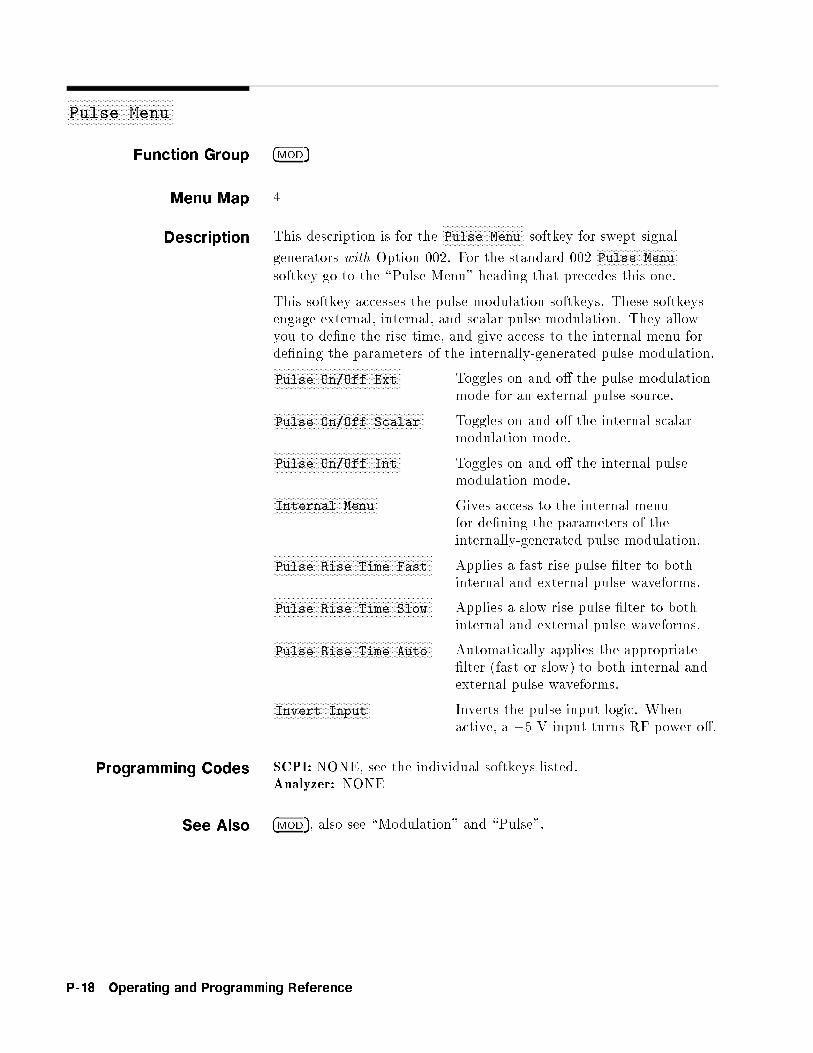
aaaaaaaaaaaaaaaaaaaaaaaaaaaaaaaaaaaaaaaaaaPulse Menu
Function Group �MOD�
Menu Map 4
Description This description is for theNNNNNNNNNNNNNNNNNNNNNNNNNNNNNNNNPulse Menu softkey for swept signal
generators with Option 002. For the standard 002NNNNNNNNNNNNNNNNNNNNNNNNNNNNNNNNPulse Menu
softkey go to the \Pulse Menu" heading that precedes this one.
This softkey accesses the pulse modulation softkeys. These softkeysengage external, internal, and scalar pulse modulation. They allowyou to de�ne the rise time, and give access to the internal menu forde�ning the parameters of the internally-generated pulse modulation.NNNNNNNNNNNNNNNNNNNNNNNNNNNNNNNNNNNNNNNNNNNNNNNNNNPulse On/Off Ext Toggles on and o� the pulse modulation
mode for an external pulse source.NNNNNNNNNNNNNNNNNNNNNNNNNNNNNNNNNNNNNNNNNNNNNNNNNNNNNNNNNNNPulse On/Off Scalar Toggles on and o� the internal scalar
modulation mode.NNNNNNNNNNNNNNNNNNNNNNNNNNNNNNNNNNNNNNNNNNNNNNNNNNPulse On/Off Int Toggles on and o� the internal pulse
modulation mode.NNNNNNNNNNNNNNNNNNNNNNNNNNNNNNNNNNNNNNNNNInternal Menu Gives access to the internal menu
for de�ning the parameters of theinternally-generated pulse modulation.NNNNNNNNNNNNNNNNNNNNNNNNNNNNNNNNNNNNNNNNNNNNNNNNNNNNNNNNNNNNNN
Pulse Rise Time Fast Applies a fast rise pulse �lter to bothinternal and external pulse waveforms.NNNNNNNNNNNNNNNNNNNNNNNNNNNNNNNNNNNNNNNNNNNNNNNNNNNNNNNNNNNNNN
Pulse Rise Time Slow Applies a slow rise pulse �lter to bothinternal and external pulse waveforms.NNNNNNNNNNNNNNNNNNNNNNNNNNNNNNNNNNNNNNNNNNNNNNNNNNNNNNNNNNNNNN
Pulse Rise Time Auto Automatically applies the appropriate�lter (fast or slow) to both internal andexternal pulse waveforms.NNNNNNNNNNNNNNNNNNNNNNNNNNNNNNNNNNNNNN
Invert Input Inverts the pulse input logic. Whenactive, a +5 V input turns RF power o�.
Programming Codes SCPI: NONE, see the individual softkeys listed.Analyzer: NONE
See Also �MOD�, also see \Modulation" and \Pulse".
P-18 Operating and Programming Reference
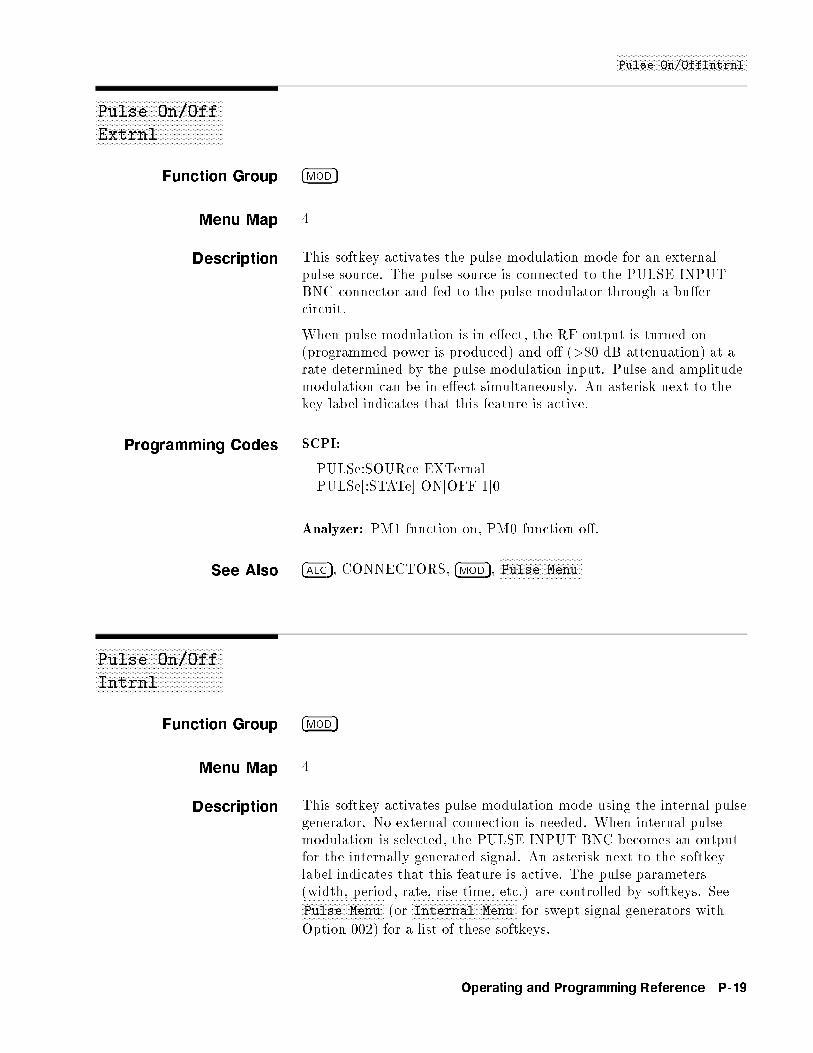
NNNNNNNNNNNNNNNNNNNNNNNNNNNNNNNNNNNNNNNNNNNNNNNNNNNPulse On/OffIntrnl
xFxFxFxFxFxFxFxFxFxFxFxFxFxFxFxFxFxFxFxFxFxFxFxFxFxFxFxFxFxFxFxFxFxFxFxFxFxFxFxFxFxFxFxFxFxFxFxFxFxF
Pulse On/Off
Extrnl
Function Group �MOD�
Menu Map 4
Description This softkey activates the pulse modulation mode for an externalpulse source. The pulse source is connected to the PULSE INPUTBNC connector and fed to the pulse modulator through a bu�ercircuit.
When pulse modulation is in e�ect, the RF output is turned on(programmed power is produced) and o� (>80 dB attenuation) at arate determined by the pulse modulation input. Pulse and amplitudemodulation can be in e�ect simultaneously. An asterisk next to thekey label indicates that this feature is active.
Programming Codes SCPI:
PULSe:SOURce EXTernalPULSe[:STATe] ONjOFFj1j0
Analyzer: PM1 function on, PM0 function o�.
See Also �ALC�, CONNECTORS, �MOD�,NNNNNNNNNNNNNNNNNNNNNNNNNNNNNNNNPulse Menu
xFxFxFxFxFxFxFxFxFxFxFxFxFxFxFxFxFxFxFxFxFxFxFxFxFxFxFxFxFxFxFxFxFxFxFxFxFxFxFxFxFxFxFxFxFxFxFxFxFxF
Pulse On/Off
Intrnl
Function Group �MOD�
Menu Map 4
Description This softkey activates pulse modulation mode using the internal pulsegenerator. No external connection is needed. When internal pulsemodulation is selected, the PULSE INPUT BNC becomes an outputfor the internally generated signal. An asterisk next to the softkeylabel indicates that this feature is active. The pulse parameters(width, period, rate, rise time, etc.) are controlled by softkeys. SeeNNNNNNNNNNNNNNNNNNNNNNNNNNNNNNNNPulse Menu (or
NNNNNNNNNNNNNNNNNNNNNNNNNNNNNNNNNNNNNNNNNInternal Menu for swept signal generators with
Option 002) for a list of these softkeys.
Operating and Programming Reference P-19

NNNNNNNNNNNNNNNNNNNNNNNNNNNNNNNNNNNNNNNNNNNNNNNNNNNPulse On/OffIntrnl
Programming Codes SCPI:
PULSe:SOURce INTernalPULSe[:STATe] ONjOFFj1j0
Analyzer: NONE
See Also �ALC�, �MOD�,NNNNNNNNNNNNNNNNNNNNNNNNNNNNNNNNPulse Menu
xFxFxFxFxFxFxFxFxFxFxFxFxFxFxFxFxFxFxFxFxFxFxFxFxFxFxFxFxFxFxFxFxFxFxFxFxFxFxFxFxFxFxFxFxFxFxFxFxFxF
Pulse On/Off
Scalar
Function Group �MOD�
Menu Map 4
Description This softkey activates pulse modulation mode, and sets the internalpulse generator to produce 27.778 kHz square wave pulses(18 �s pulse width, 36 �s pulse period). The rise and fall times ofthe RF envelope are approximately 2 �s. These pulses allow properoperation with Agilent scalar network analyzers in ac detectionmode. An asterisk next to the key label indicates that this feature isactive.
Programming Codes SCPI:
PULSe:SOURce SCALarPULSe[:STATe] ONjOFFj1j0
Analyzer: SHPM function on, PM0 function o�.
See Also �ALC�, �MOD�,NNNNNNNNNNNNNNNNNNNNNNNNNNNNNNNNPulse Menu
Chapter 3
P-20 Operating and Programming Reference
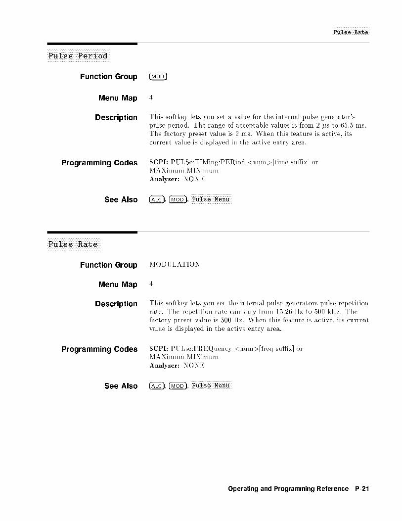
NNNNNNNNNNNNNNNNNNNNNNNNNNNNNPulse Rate
aaaaaaaaaaaaaaaaaaaaaaaaaaaaaaaaaaaaaaaaaaaaaaaaaaPulse Period
Function Group �MOD�
Menu Map 4
Description This softkey lets you set a value for the internal pulse generator'spulse period. The range of acceptable values is from 2 �s to 65.5 ms.The factory preset value is 2 ms. When this feature is active, itscurrent value is displayed in the active entry area.
Programming Codes SCPI: PULSe:TIMing:PERiod <num>[time su�x] orMAXimumjMINimumAnalyzer: NONE
See Also �ALC�, �MOD�,NNNNNNNNNNNNNNNNNNNNNNNNNNNNNNNNPulse Menu
aaaaaaaaaaaaaaaaaaaaaaaaaaaaaaaaaaaaaaaaaaPulse Rate
Function Group MODULATION
Menu Map 4
Description This softkey lets you set the internal pulse generators pulse repetitionrate. The repetition rate can vary from 15.26 Hz to 500 kHz. Thefactory preset value is 500 Hz. When this feature is active, its currentvalue is displayed in the active entry area.
Programming Codes SCPI: PULse:FREQuency <num>[freq su�x] orMAXimumjMINimumAnalyzer: NONE
See Also �ALC�, �MOD�,NNNNNNNNNNNNNNNNNNNNNNNNNNNNNNNNPulse Menu
Operating and Programming Reference P-21
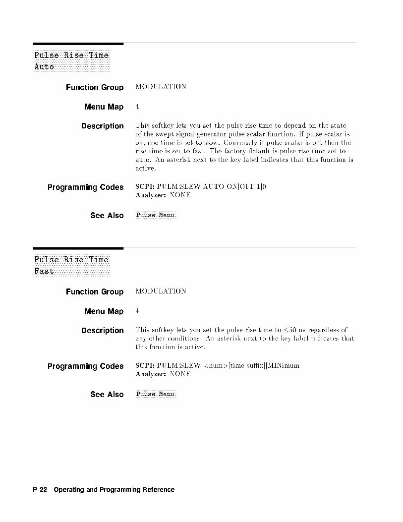
xFxFxFxFxFxFxFxFxFxFxFxFxFxFxFxFxFxFxFxFxFxFxFxFxFxFxFxFxFxFxFxFxFxFxFxFxFxFxFxFxFxFxFxFxFxFxFxFxFxFxFxFxFxFxFxFxFxFxFxFxF
Pulse Rise Time
Auto
Function Group MODULATION
Menu Map 4
Description This softkey lets you set the pulse rise time to depend on the stateof the swept signal generator pulse scalar function. If pulse scalar ison, rise time is set to slow. Conversely if pulse scalar is o�, then therise time is set to fast. The factory default is pulse rise time set toauto. An asterisk next to the key label indicates that this function isactive.
Programming Codes SCPI: PULM:SLEW:AUTO ONjOFFj1j0Analyzer: NONE
See AlsoNNNNNNNNNNNNNNNNNNNNNNNNNNNNNNNNPulse Menu
xFxFxFxFxFxFxFxFxFxFxFxFxFxFxFxFxFxFxFxFxFxFxFxFxFxFxFxFxFxFxFxFxFxFxFxFxFxFxFxFxFxFxFxFxFxFxFxFxFxFxFxFxFxFxFxFxFxFxFxFxF
Pulse Rise Time
Fast
Function Group MODULATION
Menu Map 4
Description This softkey lets you set the pulse rise time to �50 ns regardless ofany other conditions. An asterisk next to the key label indicates thatthis function is active.
Programming Codes SCPI: PULM:SLEW <num>[time su�x]jMINimumAnalyzer: NONE
See AlsoNNNNNNNNNNNNNNNNNNNNNNNNNNNNNNNNPulse Menu
P-22 Operating and Programming Reference
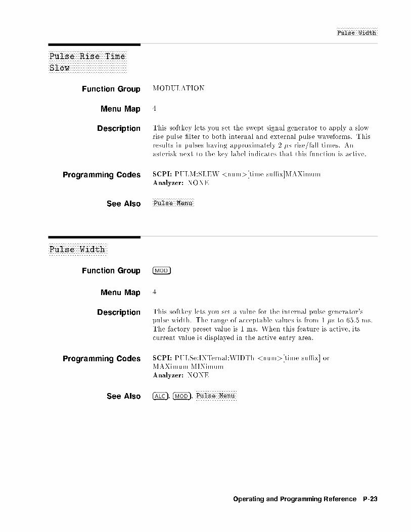
NNNNNNNNNNNNNNNNNNNNNNNNNNNNNNNNPulse Width
xFxFxFxFxFxFxFxFxFxFxFxFxFxFxFxFxFxFxFxFxFxFxFxFxFxFxFxFxFxFxFxFxFxFxFxFxFxFxFxFxFxFxFxFxFxFxFxFxFxFxFxFxFxFxFxFxFxFxFxFxF
Pulse Rise Time
Slow
Function Group MODULATION
Menu Map 4
Description This softkey lets you set the swept signal generator to apply a slowrise pulse �lter to both internal and external pulse waveforms. Thisresults in pulses having approximately 2 �s rise/fall times. Anasterisk next to the key label indicates that this function is active.
Programming Codes SCPI: PULM:SLEW <num>[time su�x]MAXimumAnalyzer: NONE
See AlsoNNNNNNNNNNNNNNNNNNNNNNNNNNNNNNNNPulse Menu
aaaaaaaaaaaaaaaaaaaaaaaaaaaaaaaaaaaaaaaaaaaaaaPulse Width
Function Group �MOD�
Menu Map 4
Description This softkey lets you set a value for the internal pulse generator'spulse width. The range of acceptable values is from 1 �s to 65.5 ms.The factory preset value is 1 ms. When this feature is active, itscurrent value is displayed in the active entry area.
Programming Codes SCPI: PULSe:INTernal:WIDTh <num>[time su�x] orMAXimumjMINimumAnalyzer: NONE
See Also �ALC�, �MOD�,NNNNNNNNNNNNNNNNNNNNNNNNNNNNNNNNPulse Menu
Operating and Programming Reference P-23
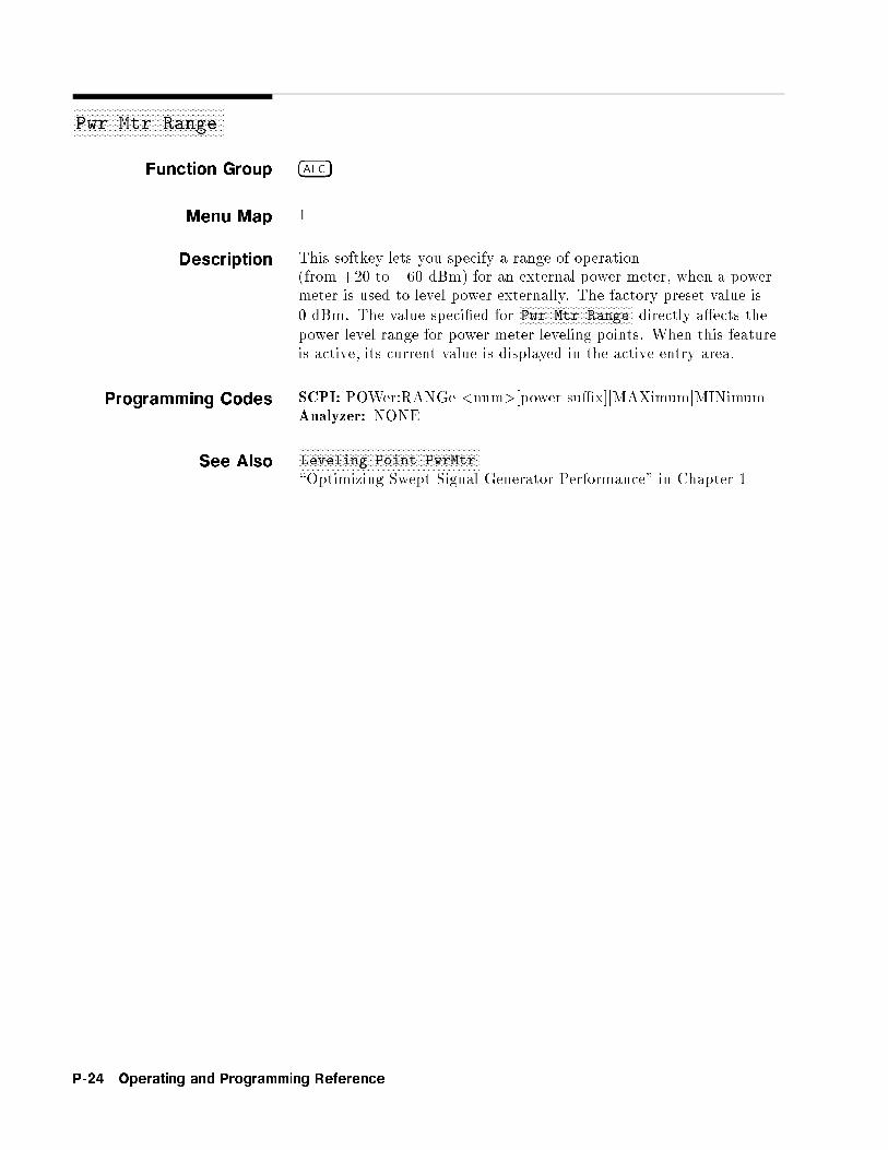
aaaaaaaaaaaaaaaaaaaaaaaaaaaaaaaaaaaaaaaaaaaaaaaaaaaaaaPwr Mtr Range
Function Group �ALC�
Menu Map 1
Description This softkey lets you specify a range of operation(from +20 to �60 dBm) for an external power meter, when a powermeter is used to level power externally. The factory preset value is0 dBm. The value speci�ed for
NNNNNNNNNNNNNNNNNNNNNNNNNNNNNNNNNNNNNNNNNPwr Mtr Range directly a�ects the
power level range for power meter leveling points. When this featureis active, its current value is displayed in the active entry area.
Programming Codes SCPI: POWer:RANGe <num>[power su�x]jMAXimumjMINimumAnalyzer: NONE
See AlsoNNNNNNNNNNNNNNNNNNNNNNNNNNNNNNNNNNNNNNNNNNNNNNNNNNNNNNNNNNNNNNNNNLeveling Point PwrMtr
\Optimizing Swept Signal Generator Performance" in Chapter 1
P-24 Operating and Programming Reference
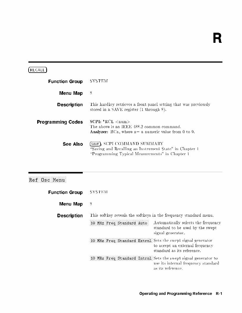
R
�RECALL�
Function Group SYSTEM
Menu Map 8
Description This hardkey retrieves a front panel setting that was previouslystored in a SAVE register (1 through 8).
Programming Codes SCPI: *RCL <num>The above is an IEEE 488.2 common command.Analyzer: RCn, where n= a numeric value from 0 to 9.
See Also �SAVE�, SCPI COMMAND SUMMARY\Saving and Recalling an Instrument State" in Chapter 1\Programming Typical Measurements" in Chapter 1
aaaaaaaaaaaaaaaaaaaaaaaaaaaaaaaaaaaaaaaaaaaaaaaaaaRef Osc Menu
Function Group SYSTEM
Menu Map 8
Description This softkey reveals the softkeys in the frequency standard menu.NNNNNNNNNNNNNNNNNNNNNNNNNNNNNNNNNNNNNNNNNNNNNNNNNNNNNNNNNNNNNNNNNNNNNNNNNNNNN10 MHz Freq Standard Auto Automatically selects the frequency
standard to be used by the sweptsignal generator.NNNNNNNNNNNNNNNNNNNNNNNNNNNNNNNNNNNNNNNNNNNNNNNNNNNNNNNNNNNNNNNNNNNNNNNNNNNNNNNNNNN
10 MHz Freq Standard Extrnl Sets the swept signal generatorto accept an external frequencystandard as its reference.NNNNNNNNNNNNNNNNNNNNNNNNNNNNNNNNNNNNNNNNNNNNNNNNNNNNNNNNNNNNNNNNNNNNNNNNNNNNNNNNNNN
10 MHz Freq Standard Intrnl Sets the swept signal generator touse its internal frequency standardas its reference.
Operating and Programming Reference R-1

NNNNNNNNNNNNNNNNNNNNNNNNNNNNNNNNNNNRef Osc Menu
NNNNNNNNNNNNNNNNNNNNNNNNNNNNNNNNNNNNNNNNNNNNNNNNNNNNNNNNNNNNNNNNNNNNNNNNNNNNN10 MHz Freq Standard None Sets the swept signal generator
to free-run operation, where nofrequency standard is used.
Programming Codes SCPI: ROSCillator:SOURce:INTernaljEXTernaljNONeAnalyzer: NONE
See Also Softkeys listed above.
�RF ON/OFF�
Function Group POWER
Menu Map NONE
Description This hardkey turns the RF power output on or o�. Press �RF ON/OFF�.If the yellow LED above the hardkey is o�, power is o�, and RF OFFappears in the message line of the display. Press the key again toturn on RF power and restore the power value last entered.
Programming Codes SCPI: POWer:STATe ONjOFFj1j0Analyzer: RF1 power on, RF0 power o�.
See Also �MOD�, �POWER LEVEL�
ROTARY KNOB
Function Group ENTRY
Menu Map NONE
Description The rotary knob is active whenever the entry area is on. It controlsa rotary pulse generator that allows analog-type adjustment of theactive entry area. Although the rotary knob has the feel of analogcontrol, it is actually a digital control that generates 120 pulses perrevolution.
Programming Codes NONE
See Also ARROW KEYS, ENTRY KEYS\Entry Area" in Chapter 1
R-2 Operating and Programming Reference
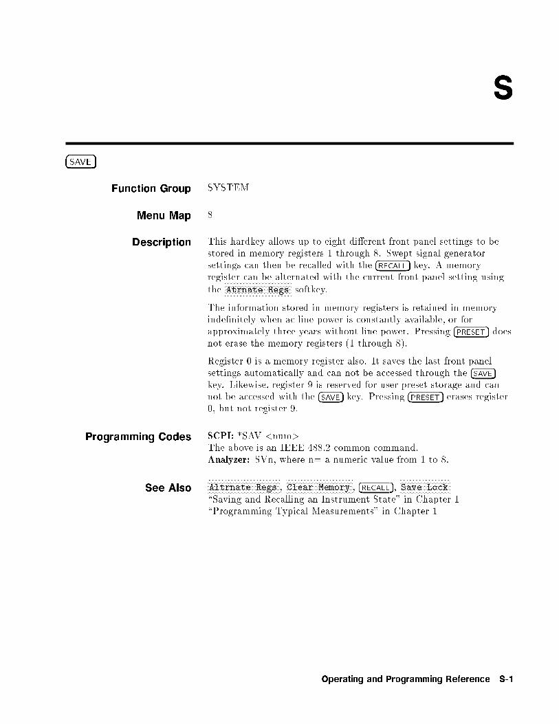
S
�SAVE�
Function Group SYSTEM
Menu Map 8
Description This hardkey allows up to eight di�erent front panel settings to bestored in memory registers 1 through 8. Swept signal generatorsettings can then be recalled with the �RECALL� key. A memoryregister can be alternated with the current front panel setting usingthe
NNNNNNNNNNNNNNNNNNNNNNNNNNNNNNNNNNNNNNAtrnate Regs softkey.
The information stored in memory registers is retained in memoryinde�nitely when ac line power is constantly available, or forapproximately three years without line power. Pressing �PRESET� doesnot erase the memory registers (1 through 8).
Register 0 is a memory register also. It saves the last front panelsettings automatically and can not be accessed through the �SAVE�key. Likewise, register 9 is reserved for user preset storage and cannot be accessed with the �SAVE� key. Pressing �PRESET� erases register0, but not register 9.
Programming Codes SCPI: *SAV <num>The above is an IEEE 488.2 common command.Analyzer: SVn, where n= a numeric value from 1 to 8.
See AlsoNNNNNNNNNNNNNNNNNNNNNNNNNNNNNNNNNNNNNNNNNAltrnate Regs ,
NNNNNNNNNNNNNNNNNNNNNNNNNNNNNNNNNNNNNNClear Memory , �RECALL�,
NNNNNNNNNNNNNNNNNNNNNNNNNNNNNSave Lock
\Saving and Recalling an Instrument State" in Chapter 1\Programming Typical Measurements" in Chapter 1
Operating and Programming Reference S-1

aaaaaaaaaaaaaaaaaaaaaaaaaaaaaaaaaaaaaaSave Lock
Function Group SYSTEM
Menu Map 8
Description This softkey lets you disable the save function. It prohibits thesaving of the present instrument state into a save/recall memoryregister. If this function is active, an error message is displayed. Anasterisk next to the key label indicates that this function is active.
Programming Codes SCPI: NONEAnalyzer: SHSV locks the registers, SHRC unlocks the registers.
See Also �SAVE�,NNNNNNNNNNNNNNNNNNNNNNNNNNNNNNNNNNNNNNNNNSecurity Menu
\Saving and Recalling an Instrument State" in Chapter 1\Programming Typical Measurements" in Chapter 1
aaaaaaaaaaaaaaaaaaaaaaaaaaaaaaaaaaaaaaaaaaaaaaaaaaaaaaaaaaaaaaaaaSave User Preset
Function Group SYSTEM
Menu Map 8
Description This softkey lets you store the present state of operation to be usedas the PRESET state. Set the swept signal generator to the desiredoperating conditions. Select
NNNNNNNNNNNNNNNNNNNNNNNNNNNNNNNNNNNNNNNNNNNNNNNNNNSave User Preset . The display shows:
--> User Defined Preset Saved
To activate this stored information, you must set the preset mode toUser.
Programming Codes SCPI: SYSTem:PRESet:SAVEAnalyzer: NONE
See AlsoNNNNNNNNNNNNNNNNNNNNNNNNNNNNNNNNNNNNNNNNNNNNNNNNNNPreset Mode User
\Changing the Preset Parameters" in Chapter 1
S-2 Operating and Programming Reference
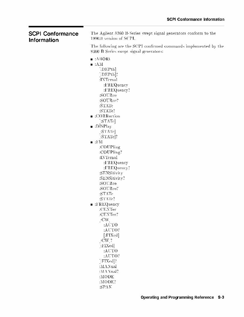
SCPI Conformance Information
SCPI ConformanceInformation
The Agilent 8360 B-Series swept signal generators conform to the1990.0 version of SCPI.
The following are the SCPI con�rmed commands implemented by the8360 B-Series swept signal generators:
:ABORt:AM[:DEPth][:DEPth]?:INTernal:FREQuency:FREQuency?
:SOURce:SOURce?:STATe:STATe?
:CORRection[:STATe]
:DISPlay[:STATe][:STATe]?
:FM:COUPling:COUPling?:INTernal:FREQuency:FREQuency?
:SENSitivity:SENSitivity?:SOURce:SOURce?:STATe:STATe?
:FREQuency:CENTer:CENTer?[:CW]:AUTO:AUTO?[:FIXed]
[:CW]?[:FIXed]:AUTO:AUTO?
[:FIXed]?:MANual:MANual?:MODE:MODE?:SPAN
Operating and Programming Reference S-3

SCPI Conformance Information
:SPAN?:STARt:STARt?:STOP:STOP?
:LIST:DWELl:POINts?
:DWELl?:FREQuency:POINts?
:FREQuency?:MARKer[n]:AOFF:FREQuency:FREQuency?:REFerence:REFerence?[:STATe][:STATe]?
:POWer:ALC:BANDwidthj:BWIDth:AUTO:AUTO?
:BANDwidthj:BWIDth?:ATTenuation:AUTO:AUTO?
:ATTenuation?[:LEVel][:LEVel]?:MODE:MODE?:RANGe:SPAN:SPAN?:STARt:STARt?:STOP:STOP?
:PULM:EXTernal:POLarity:POLarity?
:INTernal:FREQuency:FREQuency?
:SOURce:SOURce?
S-4 Operating and Programming Reference

SCPI Conformance Information
:STATe:STATe?
:PULSe:PERiod:PERiod?:WIDTh:WIDTh?
:ROSCillator:SOURce:AUTO:AUTO?
:SOURce?:STATus:OPERation:CONDition?:ENABle:ENABle?[:EVENt]?:NTRansition:NTRansition?:PTRansition:PTRansition?
:PRESet:QUEStionable:CONDition?:ENABle:ENABle?[:EVENt]?:NTRansition:NTRansition?:PTRansition:PTRansition?
:SWEep:DWELl:AUTO:AUTO?
:DWELl?:GENeration:GENeration?:MODE:MODE?:POINts:POINts?:STEP:STEP?:TIME:AUTO:AUTO?:LLIMit:LLIMit?
Operating and Programming Reference S-5
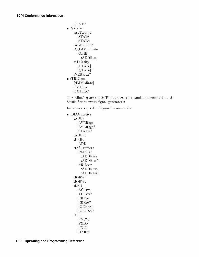
SCPI Conformance Information
:TIME?:SYSTem:ALTernate:STATe:STATe?
:ALTernate?:COMMunicate:GPIB:ADDRess
:SECurity[:STATe][:STATe]?
:VERSion?:TRIGger[:IMMediate]:SOURce:SOURce?
The following are the SCPI approved commands implemented by the8360B-Series swept signal generators:
Instrument-speci�c diagnostic commands:
:DIAGnostics:ABUS:AVERage:AVERage?:STATus?
:ABUS?:ERRor:ADD
:INSTrument:PMETer:ADDRess:ADDRess?
:PRINter:ADDRess:ADDRess?
:IORW:IORW?:LED:ACTive:ACTive?:ERRor:ERRor?:IOCHeck:IOCHeck?
:OSC:FNCW:FNDN:FNUP:HARM
S-6 Operating and Programming Reference

SCPI Conformance Information
:IF:SAMP:YO
:OUTPut:BANDcross?:FAULts?:FREQs?:UNLocks?:YODacs?:YTMDacs
:SRECeiver:ASTate:ASTate?:BCRoss:MODE:MODE?:RSWeep:SWAP:SWAP?
:BUCKet:DIVider:DIVider?
:SWEep:ARRay[0j1]:LOCK:LOCK?
:ARRay[0j1]?:RESult?:TEST:CONTinue:DATA:DESC?:MAXimum?:MINimum?:VALue?
:DISable:ENABle[:EXECute]:LOG:SOURce:SOURce?[:STATe][:STATe]?
:LOOP:LOOP?:NAME?:PATCh:DATA:DATA?:POINts?
Operating and Programming Reference S-7

SCPI Conformance Information
:DELete:POINts?:RESult?:TINT?
The following are the commands implemented by the 8360 B-Seriesswept signal generators which are not part of the SCPI de�nition:
:AM:INTernal:FUNCtion:FUNCtion?
:MODE:MODE?:TYPE:TYPE?
:CALibration:ADJust:A4:VCO:A5:LGAin:A6:VCO:A6:SMATch:A6:LGAin:A6:IFGain:A9:OFFSet:A10:MGAin:A13:REFerence:A13:GAIN:A14:SRAMp
:AM:AUTO:AUTO?[:EXECute]
:CONStants:DEFault:NAME?:RECall:SAVE
:CONStants?:PEAKing:AUTO:AUTO?[:EXECute]:FINE
:PMETer:ATTenuation:ATTenuation?:DETector:INITiate?:NEXT?
:FLATness
S-8 Operating and Programming Reference
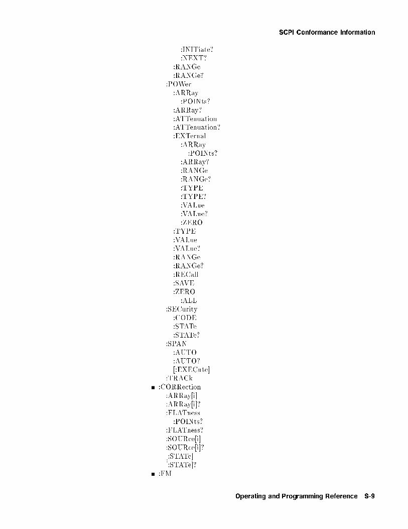
SCPI Conformance Information
:INITiate?:NEXT?
:RANGe:RANGe?
:POWer:ARRay:POINts?
:ARRay?:ATTenuation:ATTenuation?:EXTernal:ARRay:POINts?
:ARRay?:RANGe:RANGe?:TYPE:TYPE?:VALue:VALue?:ZERO
:TYPE:VALue:VALue?:RANGe:RANGe?:RECall:SAVE:ZERO:ALL
:SECurity:CODE:STATe:STATe?
:SPAN:AUTO:AUTO?[:EXECute]
:TRACk:CORRection:ARRay[i]:ARRay[i]?:FLATness:POINts?
:FLATness?:SOURce[i]:SOURce[i]?[:STATe][:STATe]?
:FM
Operating and Programming Reference S-9
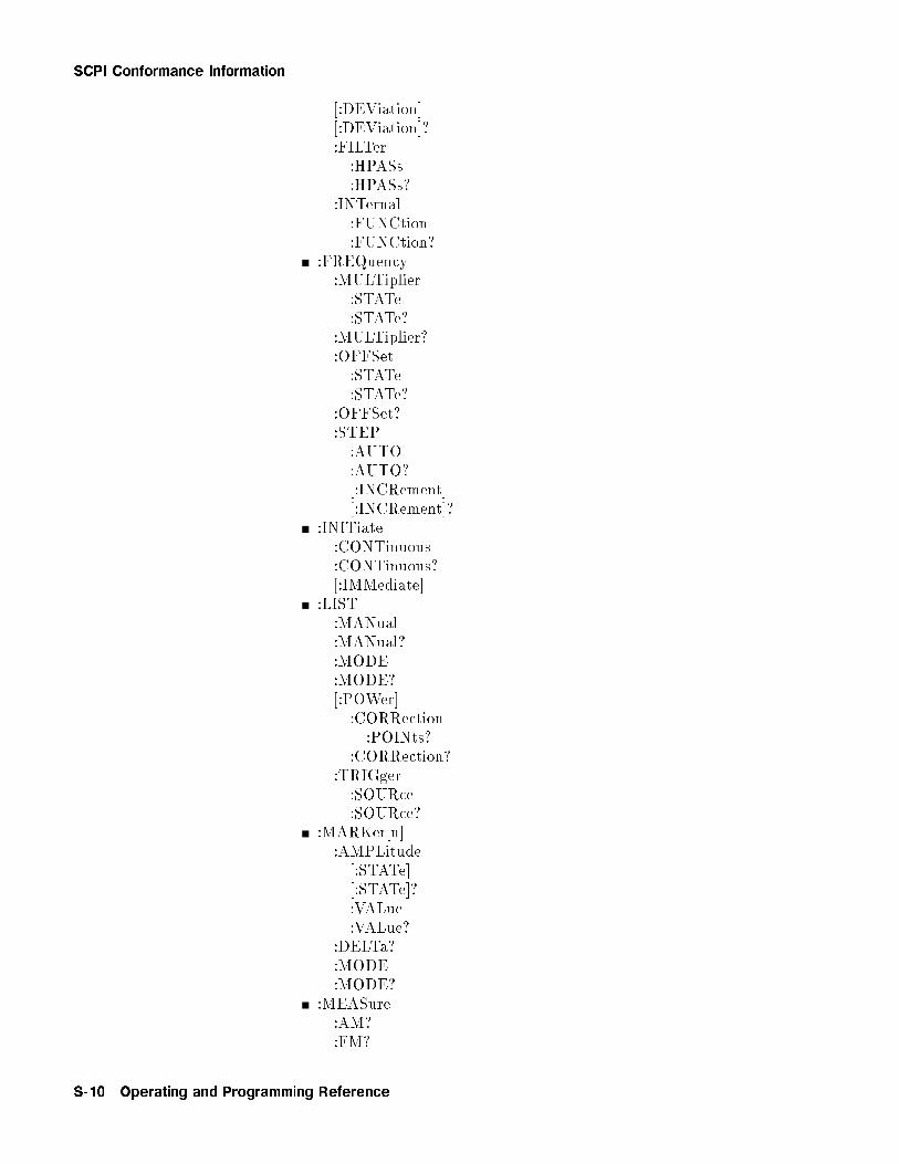
SCPI Conformance Information
[:DEViation][:DEViation]?:FILTer:HPASs:HPASs?
:INTernal:FUNCtion:FUNCtion?
:FREQuency:MULTiplier:STATe:STATe?
:MULTiplier?:OFFSet:STATe:STATe?
:OFFSet?:STEP:AUTO:AUTO?[:INCRement][:INCRement]?
:INITiate:CONTinuous:CONTinuous?[:IMMediate]
:LIST:MANual:MANual?:MODE:MODE?[:POWer]:CORRection:POINts?
:CORRection?:TRIGger:SOURce:SOURce?
:MARKer[n]:AMPLitude[:STATe][:STATe]?:VALue:VALue?
:DELTa?:MODE:MODE?
:MEASure:AM?:FM?
S-10 Operating and Programming Reference

SCPI Conformance Information
:MODulation:STATe?:OUTPut:SOURce:SOURce?:STATe:STATe?
:POWer:ALC:CFACtor:CFACtor?:SOURce:SOURce?[:STATe][:STATe]?
AMPLi�er:STATE:AUTO:AUTO?
:STATE?:CENTer:CENTer?:OFFSet:STATe:STATe?
:OFFSet?:SEARch:SLOPe:STATe:STATe?
:SLOPe?:STATe:STATe?:STEP:AUTO:AUTO?[:INCRement][:INCRement]?
:PULSe:FREQuency:FREQuency?
:PULM:EXTernal:DELay:DELay?
:INTernal:DELay:DELay?:GATE:GATE?
Operating and Programming Reference S-11

SCPI Conformance Information
:PERiod:PERiod?:TRIGger:SOURce:SOURce?
:WIDTh:WIDTh?
:SLEW:SLEW?:AUTO:AUTO?
:STATus:MSIB:CONDition?:ENABle:ENABle?[:EVENt]?:NTRansition:NTRansition?:PTRansition:PTRansition?
:SREceiver:CONDition?:ENABle:ENABle?[:EVENt]?:NTRansition:NTRansition?:PTRansition:PTRansition?
:SWEep:CONTrol:STATe:TYPE
:MANual:POINt:POINt?[:RELative][:RELative]?
:MARKer:STATe:STATe?:XFER
:TRIGger:SOURce:SOURce?
:SYSTem:DUMP:PRINter:PRINter?
S-12 Operating and Programming Reference
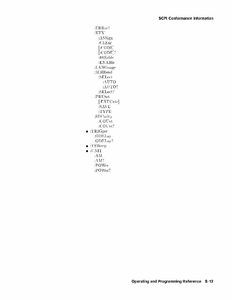
SCPI Conformance Information
:ERRor?:KEY:ASSign:CLEar[:CODE][:CODE]?:DISable:ENABle
:LANGuage:MMHead:SELect:AUTO:AUTO?
:SELect?:PRESet[:EXECute]:SAVE:TYPE
:SECurity:COUnt:COUnt?
:TRIGger:ODELay:ODELay?
:TSWeep:UNIT:AM:AM?:POWer:POWer?
Operating and Programming Reference S-13
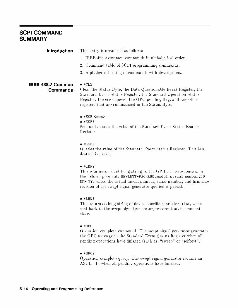
SCPI COMMANDSUMMARY
Introduction This entry is organized as follows:
1. IEEE 488.2 common commands in alphabetical order.
2. Command table of SCPI programming commands.
3. Alphabetical listing of commands with descriptions.
IEEE 488.2 CommonCommands
� *CLS
Clear the Status Byte, the Data Questionable Event Register, theStandard Event Status Register, the Standard Operation StatusRegister, the error queue, the OPC pending ag, and any otherregisters that are summarized in the Status Byte.
� *ESE <num>
� *ESE?
Sets and queries the value of the Standard Event Status EnableRegister.
� *ESR?
Queries the value of the Standard Event Status Register. This is adestructive read.
� *IDN?
This returns an identifying string to the GPIB. The response is inthe following format: HEWLETT-PACKARD,model,serial number,DD
MMM YY, where the actual model number, serial number, and �rmwarerevision of the swept signal generator queried is passed.
� *LRN?
This returns a long string of device speci�c characters that, whensent back to the swept signal generator, restores that instrumentstate.
� *OPC
Operation complete command. The swept signal generator generatesthe OPC message in the Standard Event Status Register when allpending operations have �nished (such as, \sweep" or \selftest").
� *OPC?
Operation complete query. The swept signal generator returns anASCII \1" when all pending operations have �nished.
S-14 Operating and Programming Reference
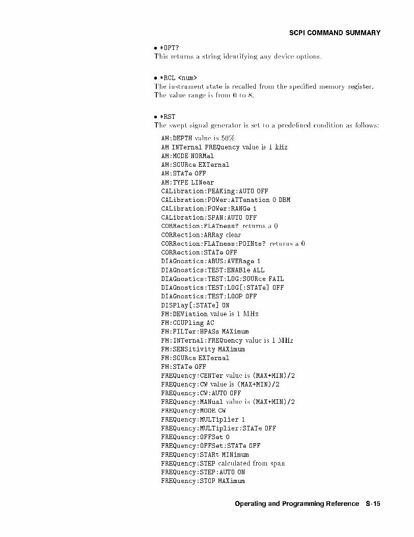
SCPI COMMAND SUMMARY
� *OPT?
This returns a string identifying any device options.
� *RCL <num>
The instrument state is recalled from the speci�ed memory register.The value range is from 0 to 8.
� *RST
The swept signal generator is set to a prede�ned condition as follows:
AM:DEPTH value is 50%AM INTernal FREQuency value is 1 kHzAM:MODE NORMal
AM:SOURce EXTernal
AM:STATe OFF
AM:TYPE LINear
CALibration:PEAKing:AUTO OFF
CALibration:POWer:ATTenation 0 DBM
CALibration:POWer:RANGe 1
CALibration:SPAN:AUTO OFFCORRection:FLATness? returns a 0CORRection:ARRay clearCORRection:FLATness:POINts? returns a 0CORRection:STATe OFF
DIAGnostics:ABUS:AVERage 1
DIAGnostics:TEST:ENABle ALL
DIAGnostics:TEST:LOG:SOURce FAIL
DIAGnostics:TEST:LOG[:STATe] OFF
DIAGnostics:TEST:LOOP OFF
DISPlay[:STATe] ON
FM:DEViation value is 1 MHzFM:COUPling AC
FM:FILTer:HPASs MAXimum
FM:INTernal:FREQuency value is 1 MHzFM:SENSitivity MAXimum
FM:SOURce EXTernal
FM:STATe OFF
FREQuency:CENTer value is (MAX+MIN)/2FREQuency:CW value is (MAX+MIN)/2FREQuency:CW:AUTO OFF
FREQuency:MANual value is (MAX+MIN)/2FREQuency:MODE CW
FREQuency:MULTiplier 1
FREQuency:MULTiplier:STATe OFF
FREQuency:OFFSet 0
FREQuency:OFFSet:STATe OFF
FREQuency:STARt MINimum
FREQuency:STEP calculated from spanFREQuency:STEP:AUTO ON
FREQuency:STOP MAXimum
Operating and Programming Reference S-15
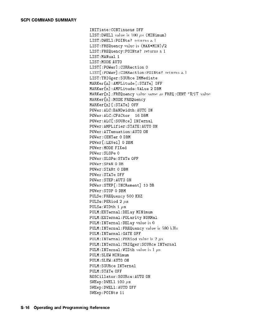
SCPI COMMAND SUMMARY
INITiate:CONTinuous OFF
LIST:DWELl value is 100 �s (MINimum)LIST:DWELl:POINts? returns a 1LIST:FREQuency value is (MAX+MIN)/2LIST:FREQuency:POINts? returns a 1LIST:MANual 1LIST:MODE AUTO
LIST[:POWer]:CORRection 0
LIST[:POWer]:CORRection:POINts? returns a 1LIST:TRIGger:SOURce IMMediate
MARKer[n]:AMPLitude[:STATe] OFF
MARKer[n]:AMPLitude:VALue 2 DBM
MARKer[n]:FREQuency value same as FREQ:CENT *RST valueMARKer[n]:MODE FREQuency
MARKer[n][:STATe] OFF
POWer:ALC:BANDwidth:AUTO ON
POWer:ALC:CFACtor �16 DBM
POWer:ALC[:SOURce] INTernal
POWer:AMPLifier:STATE:AUTO ON
POWer:ATTenuation:AUTO ON
POWer:CENTer 0 DBM
POWer[:LEVel] 0 DBM
POWer:MODE FIXed
POWer:SLOPe 0
POWer:SLOPe:STATe OFF
POWer:SPAN 0 DB
POWer:STARt 0 DBM
POWer:STATe OFF
POWer:STEP:AUTO ON
POWer:STEP[:INCRement] 10 DB
POWer:STOP 0 DBM
PULSe:FREQuency 500 KHZ
PULSe:PERiod 2 �s
PULSe:WIDth 1 �sPULM:EXTernal:DELay MINimum
PULM:EXTernal:POLarity NORMal
PULM:INTernal:DELay value is 0PULM:INTernal:FREQuency value is 500 kHzPULM:INTernal:GATE OFF
PULM:INTernal:PERiod value is 2 �sPULM:INTernal:TRIGger:SOURce INTernal
PULM:INTernal:WIDth value is 1 �sPULM:SLEW MINimum
PULM:SLEW:AUTO ON
PULM:SOURce INTernal
PULM:STATe OFF
ROSCillator:SOURce:AUTO ON
SWEep:DWELl 100 �s
SWEep:DWELl:AUTO OFF
SWEep:POINts 11
S-16 Operating and Programming Reference

SCPI COMMAND SUMMARY
SWEep:STEP value is (StopMAX-StartMIN)/10SWEep:TIME MINimum
SWEep:TIME:AUTO ON
SWEep:TIME:LLIMit 10 ms
SWEep:GENeration ANALog
SWEep:MODE AUTOSWEep:MANual:POINt 1
SWEep:MANual[:RELative] 0.50
SWEep:MARKer:STATe OFF
SYSTem:ALTernate 1
SYSTem:ALTernate:STATe OFF
SYSTem:COMMunicate:GPIB:ADDRess 19
SYSTem:MMHead:SELect:AUTO ON
SYSTem:SECurity:COUNt 1
UNIT:AM PCT *UNIT:POWer DBM
� *SAV <num>
The present instrument state is stored in the speci�ed memoryregister. The acceptable numeric range is from 1 to 8. An executionerror occurs if you try to save state 0.
� *SRE <num> � *SRE?
Sets and queries the value of the Service Request Enable Register.
� *STB?
Queries the Status Byte. This is a non-destructive read.
� *TRG
This command performs the same function as the Group ExecuteTrigger command de�ned by IEEE 488.1.
� *TST?
A full selftest is performed, without data logging or looping, andreturns one of the following error codes:
Error Code De�nition0 Test passed.1 Test failed.2 Test not run yet. (This is an unlikely event.)3 Test aborted.4 Can not execute the test.5 Can not execute the test, test skipped.�1 Unrecognized result, software defect.
Operating and Programming Reference S-17
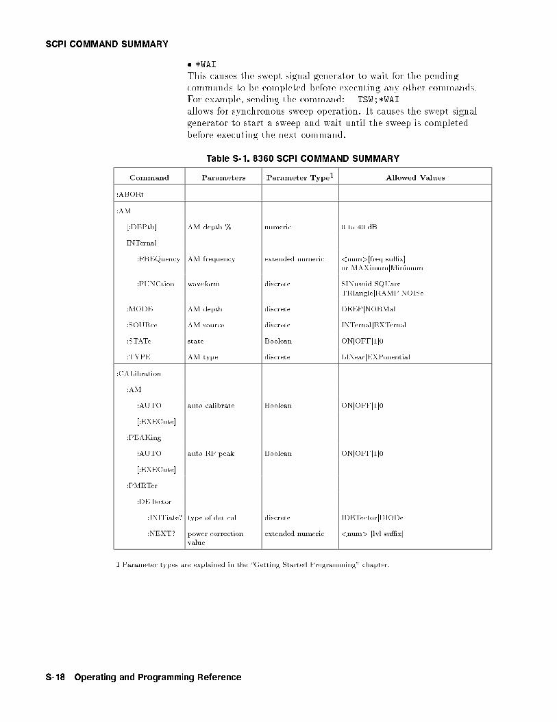
SCPI COMMAND SUMMARY
� *WAI
This causes the swept signal generator to wait for the pendingcommands to be completed before executing any other commands.For example, sending the command: TSW;*WAI
allows for synchronous sweep operation. It causes the swept signalgenerator to start a sweep and wait until the sweep is completedbefore executing the next command.
Table S-1. 8360 SCPI COMMAND SUMMARY
Command Parameters Parameter Type1 Allowed Values
:ABORt
:AM
[:DEPth] AM depth % numeric 0 to 40 dB
INTernal
:FREQuency AM frequency extended numeric <num>[freq su�x]or MAXimumjMinimum
:FUNCtion waveform discrete SINusoidjSQUareTRIanglejRAMPjNOISe
:MODE AM depth discrete DEEPjNORMal
:SOURce AM source discrete INTernaljEXTernal
:STATe state Boolean ONjOFFj1j0
:TYPE AM type discrete LINearjEXPonential
:CALibration
:AM
:AUTO auto calibrate Boolean ONjOFFj1j0
[:EXECute]
:PEAKing
:AUTO auto RF peak Boolean ONjOFFj1j0
[:EXECute]
:PMETer
:DETector
:INITiate? type of det cal discrete IDETectorjDIODe
:NEXT? power correctionvalue
extended numeric <num> [lvl su�x]
1 Parameter types are explained in the \Getting Started Programming" chapter.
S-18 Operating and Programming Reference
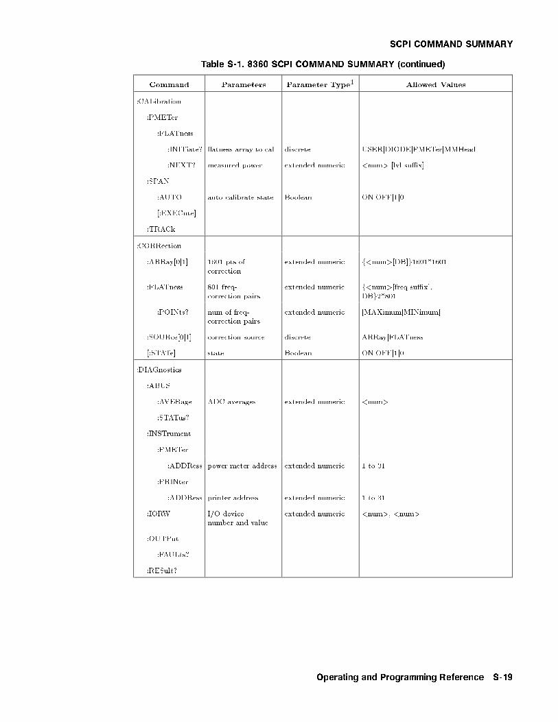
SCPI COMMAND SUMMARY
Table S-1. 8360 SCPI COMMAND SUMMARY (continued)
Command Parameters Parameter Type1 Allowed Values
:CALibration
:PMETer
:FLATness
:INITiate? atness array to cal discrete USERjDIODEjPMETerjMMHead
:NEXT? measured power extended numeric <num> [lvl su�x]
:SPAN
:AUTO auto calibrate state Boolean ONjOFFj1j0
[:EXECute]
:TRACk
:CORRection
:ARRay[0j1] 1601 pts ofcorrection
extended numeric f<num>[DB]g1601*1601
:FLATness 801 freq-correction pairs
extended numeric f<num>[freq su�x],DBg2*801
:POINts? num of freq-correction pairs
extended numeric [MAXimumjMINimum]
:SOURce[0j1] correction source discrete ARRayjFLATness
[:STATe] state Boolean ONjOFFj1j0
:DIAGnostics
:ABUS
:AVERage ADC averages extended numeric <num>
:STATus?
:INSTrument
:PMETer
:ADDRess power meter address extended numeric 1 to 31
:PRINter
:ADDRess printer address extended numeric 1 to 31
:IORW I/O devicenumber and value
extended numeric <num>, <num>
:OUTPut
:FAULts?
:RESult?
Operating and Programming Reference S-19

SCPI COMMAND SUMMARY
Table S-1. 8360 SCPI COMMAND SUMMARY (continued)
Command Parameters Parameter Type1 Allowed Values
:DIAGnostics
:TEST
:CONTinue
:DATA
:DESC?
:MAXimum?
:MINimum?
:VALue?
:DISable disable listedselftests
extended numericor discrete
f<num>g1*?jALL
:ENABle enable listedselftests
extended numericor discrete
f<num>g1*?jALL
[:EXECute] extended numeric 0 to 288
:LOG
:SOURce log when discrete ALLjFAIL
[:STATe] state Boolean ONjOFFj1j0
:LOOP state Boolean ONjOFFj1j0
:NAME? selftest number extended numeric 0 to 288
:POINts? number of selftests
:RESult? condition of selftests
:TINT?
:DISPlay
[:STATe] state Boolean ONjOFFj1j0
:FM
:COUPling coupling type discrete ACjDC
[:DEViation] peak FM deviation extended numeric <num>[freq su�x]or MAXimumjMINimum
:FILTer
:HPASs FM AC Bandwidth extended numeric <num>[freq su�x]or MAXimumjMINimum
:INTernal
:FREQuency FM frequency extended numeric <num>[freq su�x]or MAXimumjMINimum
:FUNCtion FM waveform discrete SINusoidjSQUareTRIanglejRAMPjNOISe
:SENSitivity extended numeric 100KHZ/Vj1MHZ/Vj10MHZ/Vor MAXimumjMINimum
S-20 Operating and Programming Reference
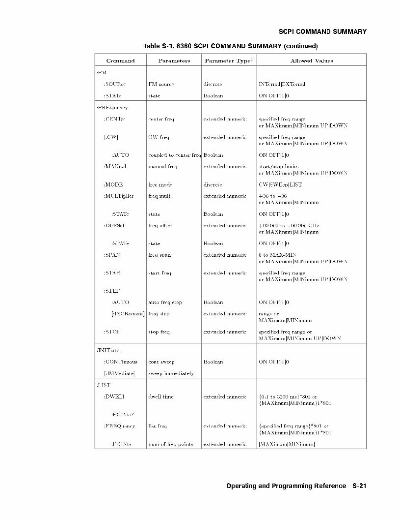
SCPI COMMAND SUMMARY
Table S-1. 8360 SCPI COMMAND SUMMARY (continued)
Command Parameters Parameter Type1 Allowed Values
:FM
:SOURce FM source discrete INTernaljEXTernal
:STATe state Boolean ONjOFFj1j0
:FREQuency
:CENTer center freq extended numeric speci�ed freq rangeor MAXimumjMINimumjUPjDOWN
[:CW] CW freq extended numeric speci�ed freq rangeor MAXimumjMINimumjUPjDOWN
:AUTO coupled to center freq Boolean ONjOFFj1j0
:MANual manual freq extended numeric start/stop limitsor MAXimumjMINimumjUPjDOWN
:MODE free mode discrete CWjSWEepjLIST
:MULTiplier freq mult extended numeric +36 to �36or MAXimumjMINimum
:STATe state Boolean ONjOFFj1j0
:OFFSet freq o�set extended numeric +99.999 to �99.999 GHzor MAXimumjMINimum
:STATe state Boolean ONjOFFj1j0
:SPAN freq span extended numeric 0 to MAX-MINor MAXimumjMINimumjUPjDOWN
:STARt start freq extended numeric speci�ed freq rangeor MAXimumjMINimumjUPjDOWN
:STEP
:AUTO auto freq step Boolean ONjOFFj1j0
[:INCRement] freq step extended numeric range orMAXimumjMINimum
:STOP stop freq extended numeric speci�ed freq range orMAXimumjMINimumjUPjDOWN
:INITiate
:CONTinuous cont sweep Boolean ONjOFFj1j0
[:IMMediate] sweep immediately
:LIST
:DWELl dwell time extended numeric f0.1 to 3200 msg*801 orfMAXimumjMINimumg1*801
:POINts?
:FREQuency list freq extended numeric fspeci�ed freq rangeg*801 orfMAXimumjMINimumg1*801
:POINts num of freq points extended numeric [MAXimumjMINimum]
Operating and Programming Reference S-21

SCPI COMMAND SUMMARY
Table S-1. 8360 SCPI COMMAND SUMMARY (continued)
Command Parameters Parameter Type1 Allowed Values
:LIST
:MANual num of pointsto lock on
numeric 1 to maximum de�ned
:MODE list sweep mode discrete AUTOjMANual
[:POWer]
:CORRection correction level extended numeric f+40 to �40 DBg1*801 orfMAXimumjMINimumg1*801
:POINts? num of corr levels numeric [MAXimumjMINimum]
:TRIGger
:SOURce list trig source discrete IMMediatejBUSjEXTernal
:MARKer[n] [n] is 1 to 5 (1 is the default)
:AMPLitude
[:STATe] state Boolean ONjOFFj1j0
:VALue amp marker depth extended numeric +10 to�10DBjMAXimumjMINimum
:AOFF
:DELTa? di�erence betweentwo markers
numeric <num>,<num> 1 to 5
:FREQuency marker frequency extended numeric speci�ed freq rangeor MAXimumjMINimum
:MODE marker mode discrete FREQuencyjDELTa
:REFerence delta marker ref numeric 1 to 5
[:STATe] state Boolean ONjOFFj1j0
:MODulation
:OUTPut
:SOURce output mod source discrete AMjFM
:STATe output mod state Boolean ONjOFFj1j0
:STATe? state Boolean ONjOFFj1j0
:POWer
:ALC
:BANDwidth ALC bwidth extended numeric <num>[freq su�x]or MAXimumjMINimum
:AUTO bwidth selection Boolean ONjOFFj1j0
:CFACtor coupling factor extended numeric 0 to �90[DB] orMAXimumjMINimumjUPjDOWN
:SOURce leveling point discrete INTernaljDIODejPMETerjMMHead
[:STATe] state Boolean ONjOFFj1j0
S-22 Operating and Programming Reference
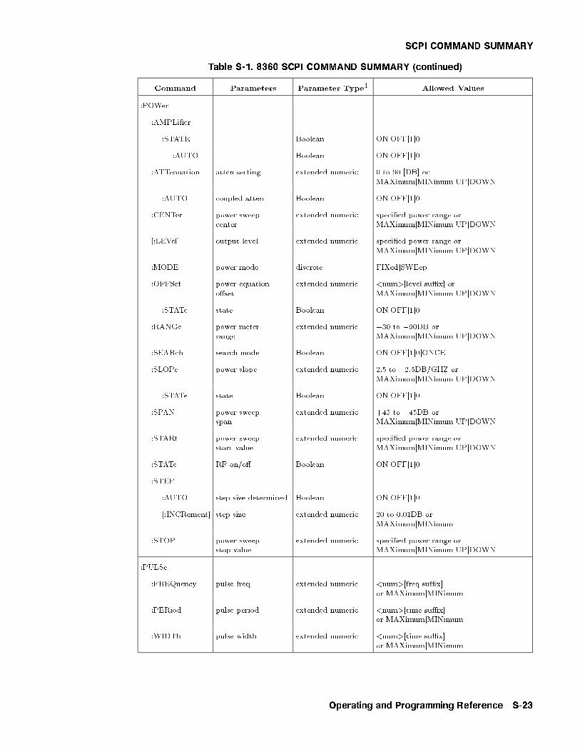
SCPI COMMAND SUMMARY
Table S-1. 8360 SCPI COMMAND SUMMARY (continued)
Command Parameters Parameter Type1 Allowed Values
:POWer
:AMPLi�er
:STATE Boolean ONjOFFj1j0
:AUTO Boolean ONjOFFj1j0
:ATTenuation atten setting extended numeric 0 to 90 [DB] orMAXimumjMINimumjUPjDOWN
:AUTO coupled atten Boolean ONjOFFj1j0
:CENTer power sweepcenter
extended numeric speci�ed power range orMAXimumjMINimumjUPjDOWN
[:LEVel] output level extended numeric speci�ed power range orMAXimumjMINimumjUPjDOWN
:MODE power mode discrete FIXedjSWEep
:OFFSet power equationo�set
extended numeric <num>[level su�x] orMAXimumjMINimumjUPjDOWN
:STATe state Boolean ONjOFFj1j0
:RANGe power meterrange
extended numeric �30 to �90DB orMAXimumjMINimumjUPjDOWN
:SEARch search mode Boolean ONjOFFj1j0jONCE
:SLOPe power slope extended numeric 2.5 to �2.5DB/GHZ orMAXimumjMINimumjUPjDOWN
:STATe state Boolean ONjOFFj1j0
:SPAN power sweepspan
extended numeric +45 to �45DB orMAXimumjMINimumjUPjDOWN
:STARt power sweepstart value
extended numeric speci�ed power range orMAXimumjMINimumjUPjDOWN
:STATe RF on/o� Boolean ONjOFFj1j0
:STEP
:AUTO step size determined Boolean ONjOFFj1j0
[:INCRement] step size extended numeric 20 to 0.01DB orMAXimumjMINimum
:STOP power sweepstop value
extended numeric speci�ed power range orMAXimumjMINimumjUPjDOWN
:PULSe
:FREQuency pulse freq extended numeric <num>[freq su�x]or MAXimumjMINimum
:PERiod pulse period extended numeric <num>[time su�x]or MAXimumjMINimum
:WIDTh pulse width extended numeric <num>[time su�x]or MAXimumjMINimum
Operating and Programming Reference S-23
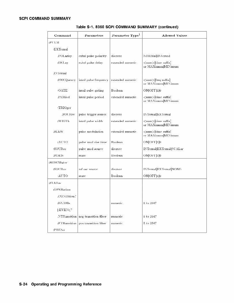
SCPI COMMAND SUMMARY
Table S-1. 8360 SCPI COMMAND SUMMARY (continued)
Command Parameters Parameter Type1 Allowed Values
:PULM
:EXTernal
:POLarity extnl pulse polarity discrete NORMaljINVerted
:DELay extnl pulse delay extended numeric <num>[time su�x]or MAXimumjMINimum
:INTernal
:FREQuency intnl pulse frequency extended numeric <num>[freq su�x]or MAXimumjMINimum
:GATE intnl pulse gating Boolean ONjOFFj1j0
:PERiod intnl pulse period extended numeric <num>[time su�x]or MAXimumjMINimum
:TRIGger
:SOURce pulse trigger source discrete INTernaljEXTernal
:WIDTh intnl pulse width extended numeric <num>[time su�x]or MAXimumjMINimum
:SLEW pulse modulation extended numeric <num>[time su�x]or MAXimumjMINimum
:AUTO pulse mod rise time Boolean ONjOFFj1j0
:SOURce pulse mod source discrete INTernaljEXTernaljSCALar
:STATe state Boolean ONjOFFj1j0
:ROSCillator
:SOURce ref osc source discrete INTernaljEXTernaljNONE
:AUTO state Boolean ONjOFFj1j0
:STATus
:OPERation
:CONDition?
:ENABle numeric 0 to 2047
[:EVENt]?
:NTRansition neg transition �lter numeric 0 to 2047
:PTRansition pos transition �lter numeric 0 to 2047
:PRESet
S-24 Operating and Programming Reference

SCPI COMMAND SUMMARY
Table S-1. 8360 SCPI COMMAND SUMMARY (continued)
Command Parameters Parameter Type1 Allowed Values
:STATus
:QUEStionable
:CONDition?
:ENABle SRQ enable register numeric 0 to 2047
[:EVENt]?
:NTRansition neg transition �lter numeric 0 to 2047
:PTRansition pos transition �lter numeric 0 to 2047
:SWEep
:CONTrol
:STATe dual source mode Boolean ONjOFFj1j0
:TYPE type ofsweep control
discrete MASTerjSLAVe
:DWELl settling timeplus dwell time
extended numeric 0.1 to 3200 msor MAXimumjMINimum
:AUTO dwell calculationstate
Boolean ONjOFFj1j0
:GENeration type of sweep discrete STEPpedjANALog
:MANual
:POINt step point number numeric 1 to the number of step points
[:RELative] percent of sweep extended numeric 0 to 100%
:MARKer
:STATe state Boolean ONjOFFj1j0
:XFER M1=start,M2=stop
:MODE manual sweepmode switch
discrete AUTOjMANual
:POINts points in step sweep numeric <num>jMAXimumjMINimum
:STEP step size extended numeric function of current spanMAXimumjMINimum
:TIME sweep time extended numeric 200s to 133 ms orMAXimumjMINimum
:AUTO auto sweeptime switch
Boolean ONjOFFj1j0
:LLIMit fastest sweeptime
extended numeric <num>[time su�x]or MAXimumjMINimum
:TRIGger
:SOURce stepped trig source discrete IMMediatejBUSjEXTernal
Operating and Programming Reference S-25

SCPI COMMAND SUMMARY
Table S-1. 8360 SCPI COMMAND SUMMARY (continued)
Command Parameters Parameter Type1 Allowed Values
:SYSTem
:ALTernate save/recall register numeric 1 to 8jMAXimumjMINimum
:STATe state Boolean ONjOFFj1j0
:COMMunicate
:GPIB
:ADDRess instrument address numeric 1 to 30
:DUMP
:PRINter?
:ERRor?
:KEY
:ASSign key code assign numeric 0 to 511, 1 to 14 excluding 5 and 10
:CLEar clears user menu numeric 1 to 14jALL
:DISable save lock discrete SAVE
:ENABle save lock discrete SAVE
:LANGuage language selection discrete SCPIjCIILjCOMPatible
:MMHead
SELect discrete FRONtjREARjNONE
AUTO Boolean ONjOFFj0j1
:PRESet
[:EXEC]
:SAVE
:TYPE preset mode discrete FACToryjUSER
:SECurity
:COUnt memory clear numeric 0 to 32767jMAXimumjMINimum
[:STATe] state Boolean ONjOFFj1j0
:VERSion?
:TRIGger
[:IMMediate]
:ODELay output delay extended numeric 0 to 3.2s
:SOURce trig source discrete IMMediatejBUSjEXTernal
:TSWeep equivalent of :ABORt;INITiate[:IMMediate]
:UNIT
:AM AM depth units discrete DBjPCT
:POWer default power units string DBM
S-26 Operating and Programming Reference
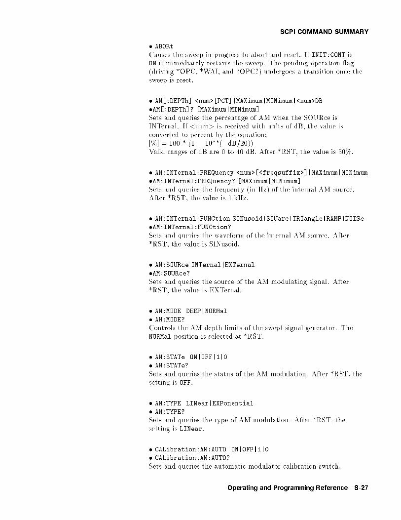
SCPI COMMAND SUMMARY
� ABORt
Causes the sweep in progress to abort and reset. If INIT:CONT isON it immediately restarts the sweep. The pending operation ag(driving *OPC, *WAI, and *OPC?) undergoes a transition once thesweep is reset.
� AM[:DEPTh] <num>[PCT]|MAXimum|MINimum|<num>DB
�AM[:DEPTh]? [MAXimum|MINimum]
Sets and queries the percentage of AM when the SOURce isINTernal. If <num> is received with units of dB, the value isconverted to percent by the equation:[%] = 100 * (1 � 10**(�dB/20))Valid ranges of dB are 0 to 40 dB. After *RST, the value is 50%.
� AM:INTernal:FREQuency <num>[<freqsuffix>]|MAXimum|MINimum
�AM:INTernal:FREQuency? [MAXimum|MINimum]
Sets and queries the frequency (in Hz) of the internal AM source.After *RST, the value is 1 kHz.
� AM:INTernal:FUNCtion SINusoid|SQUare|TRIangle|RAMP|NOISe
�AM:INTernal:FUNCtion?Sets and queries the waveform of the internal AM source. After*RST, the value is SINusoid.
� AM:SOURce INTernal|EXTernal
�AM:SOURce?Sets and queries the source of the AM modulating signal. After*RST, the value is EXTernal.
� AM:MODE DEEP|NORMal
� AM:MODE?
Controls the AM depth limits of the swept signal generator. TheNORMal position is selected at *RST.
� AM:STATe ON|OFF|1|0
� AM:STATe?
Sets and queries the status of the AM modulation. After *RST, thesetting is OFF.
� AM:TYPE LINear|EXPonential
� AM:TYPE?
Sets and queries the type of AM modulation. After *RST, thesetting is LINear.
� CALibration:AM:AUTO ON|OFF|1|0
� CALibration:AM:AUTO?
Sets and queries the automatic modulator calibration switch.
Operating and Programming Reference S-27

SCPI COMMAND SUMMARY
If this is ON, each time a frequency or power is changed,CALibration:AM[:EXECute] is attempted.
� CALibration:AM[:EXECute]
When AM is on and the swept signal generator is in the CW ormanual mode, the swept signal generator performs a modulatorcalibration as long as power sweep is not active.
� CALibration:PEAKing:AUTO ON|OFF|1|0
� CALibration:PEAKing:AUTO?
Sets and queries the automatic peaking function. If AUTO is ON, thena peak is done at regular intervals automatically. After *RST, thesetting is OFF.
� CALibration:PEAKing[:EXECute]
Peaks the SYTM.
� CALibration:PMETer:DETector:INITiate? IDETector|DIODeInitiates the speci�ed calibration. These calibrations require the useof an external power measurement. Once initiated, the swept signalgenerator sets up for the �rst point to be measured, and responds tothe query with the frequency at which the power is to be measured.
The parameters mean:
IDETector Initiates a calibration of the internal detector loggerbreakpoints and o�sets.
DIODe Initiates a calibration of an external detector's loggerbreakpoints and o�sets.
� CALibration:PMETer:DETector:NEXT? <num>[lvl suffix]
The parameter is the measured power that is currently produced bythe swept signal generator. You must supply this parameter aftermeasuring the power using an external power meter. The queryresponse is issued after the swept signal generator processes thesupplied parameter and settles on the next point to be measured.The query response is:
>0 The frequency [in Hz] that is currently produced.0 The calibration is complete.<0 An error has occurred and the calibration is aborted.
� CALibration:PMETer:FLATness:INITiate?
USER|DIODe|PMETer|MMHead
Initiates the speci�ed calibration. These calibrations require the useof an external power measurement. Once initiated, the swept signalgenerator sets up for the �rst point to be measured, and responds tothe query with the frequency at which the power is to be measured.
The parameters mean :
USER Initiates a calibration at all of the user atness points.
S-28 Operating and Programming Reference

SCPI COMMAND SUMMARY
DIODe Initiates a calibration of the external atness. Depends onvalue of CALibration:PMETer:RANGe.
PMETer Initiates a calibration of the power meter atness.Depends on value of CALibration:PMETer:RANGe.
MMHead Initiates a calibration of the source module atness.Depends on value of CALibration:PMETer:RANGe.
� CALibration:PMETer:FLATness:NEXT? <num>[lvl suffix]The parameter is the measured power that is currently produced bythe swept signal generator. You must supply this parameter aftermeasuring the power using an external power meter. The queryresponse is issued after the swept signal generator processes thesupplied parameter and settles on the next point to be measured.The query response is:
>0 The frequency [in Hz] that is currently produced.0 The calibration is complete.<0 An error has occurred and the calibration is aborted.
� CALibration:SPAN:AUTO ON|OFF|1|0
� CALibration:SPAN:AUTO?
Sets and queries the automatic sweep span calibration.
ON A calibration is done whenever the sweep span is changed.OFF A calibration is done only when
CALibration:SPAN[:EXECute] is sent.
After *RST, the setting is OFF.
� CALibration:SPAN[:EXECute]
Causes a sweep span calibration.
� CALibration:TRACk
Causes an automatic tracking calibration procedure.
� CORRection:ARRay[i] {<num>[DB]}1601*1601
� CORRection:ARRay[i]?
Sets and queries the entire 1601-point array of correction valuesthat can be added to the internal atness correction array. The1601-points are added to the internal atness array synchronizedon the trigger output 1�s pulses. These TTL-level pulses are 1601evenly spaced points across an analog sweep, or at each point in stepor list mode. Entering this array causes the CORRection:SOURce[i]command to set to ARRay. There is one array for the foregroundstate (i=0) and one for the background state (i=1). If the [i] is notspeci�ed, the default value is i=0. After *RST, these arrays arecleared.
Operating and Programming Reference S-29
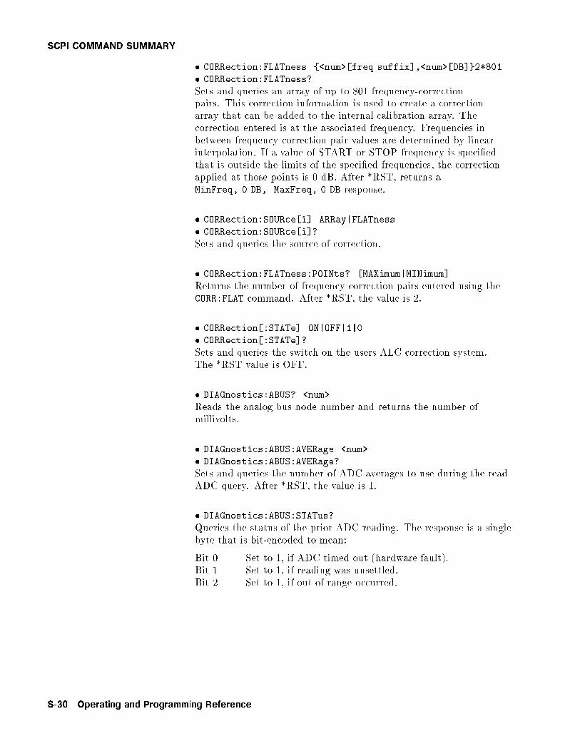
SCPI COMMAND SUMMARY
� CORRection:FLATness {<num>[freq suffix],<num>[DB]}2*801
� CORRection:FLATness?
Sets and queries an array of up to 801 frequency-correctionpairs. This correction information is used to create a correctionarray that can be added to the internal calibration array. Thecorrection entered is at the associated frequency. Frequencies inbetween frequency-correction pair values are determined by linearinterpolation. If a value of START or STOP frequency is speci�edthat is outside the limits of the speci�ed frequencies, the correctionapplied at those points is 0 dB. After *RST, returns aMinFreq, 0 DB, MaxFreq, 0 DB response.
� CORRection:SOURce[i] ARRay|FLATness
� CORRection:SOURce[i]?
Sets and queries the source of correction.
� CORRection:FLATness:POINts? [MAXimum|MINimum]
Returns the number of frequency-correction pairs entered using theCORR:FLAT command. After *RST, the value is 2.
� CORRection[:STATe] ON|OFF|1|0
� CORRection[:STATe]?
Sets and queries the switch on the users ALC correction system.The *RST value is OFF.
� DIAGnostics:ABUS? <num>
Reads the analog bus node number and returns the number ofmillivolts.
� DIAGnostics:ABUS:AVERage <num>
� DIAGnostics:ABUS:AVERage?
Sets and queries the number of ADC averages to use during the readADC query. After *RST, the value is 1.
� DIAGnostics:ABUS:STATus?
Queries the status of the prior ADC reading. The response is a singlebyte that is bit-encoded to mean:
Bit 0 Set to 1, if ADC timed out (hardware fault).Bit 1 Set to 1, if reading was unsettled.Bit 2 Set to 1, if out of range occurred.
S-30 Operating and Programming Reference

SCPI COMMAND SUMMARY
� DIAGnostics:INSTrument:PMETer:ADDRess <num>
� DIAGnostics:INSTrument:PMETer:ADDRess?
Sets and queries the GPIB address to use for the power meter duringswept signal generator calibration routines. Allowable values are 0through 31. *RST or power on does not e�ect this value. Default is13. It is defaulted only when memory is initialized.
� DIAGnostics:INSTrument:PRINter:ADDRess <num>
� DIAGnostics:INSTrument:PRINter:ADDRess?
Sets the GPIB address of the printer to use during some of thecalibration procedures when the swept signal generator assumesGPIB control. *RST and power on do not e�ect this command. Thedefault is 1. The default value is set at memory initialization only.
� DIAGnostics:IORW <num>,<num>
Performs a write to the I/O Device number speci�ed in the �rst<num> and sets it to the value in the second <num>.
� DIAGnostics:IORW? <num>
Reads from the speci�ed I/O device number and returns the responsedata.
� DIAGnostics:OUTPut:FAULt?
Returns a string of 16, 1s and 0s that are equivalent to the faultdisplay.
Bit 0 = PEAKBit 1 = TRACKBit 2 = RAMPBit 3 = SPANBit 4 = V/GHzBit 5 = ADCBit 6 = EEROMBit 7 = PWRONBit 8 = CALCOBit 9 = PLLZEROBit 10 = PLLWAITBit 11 = FNXFERBit 12 = CAL YOBit 13 = CAL MANBit 14 = TMR CNFLCTBit 15 = SEARCH
Operating and Programming Reference S-31
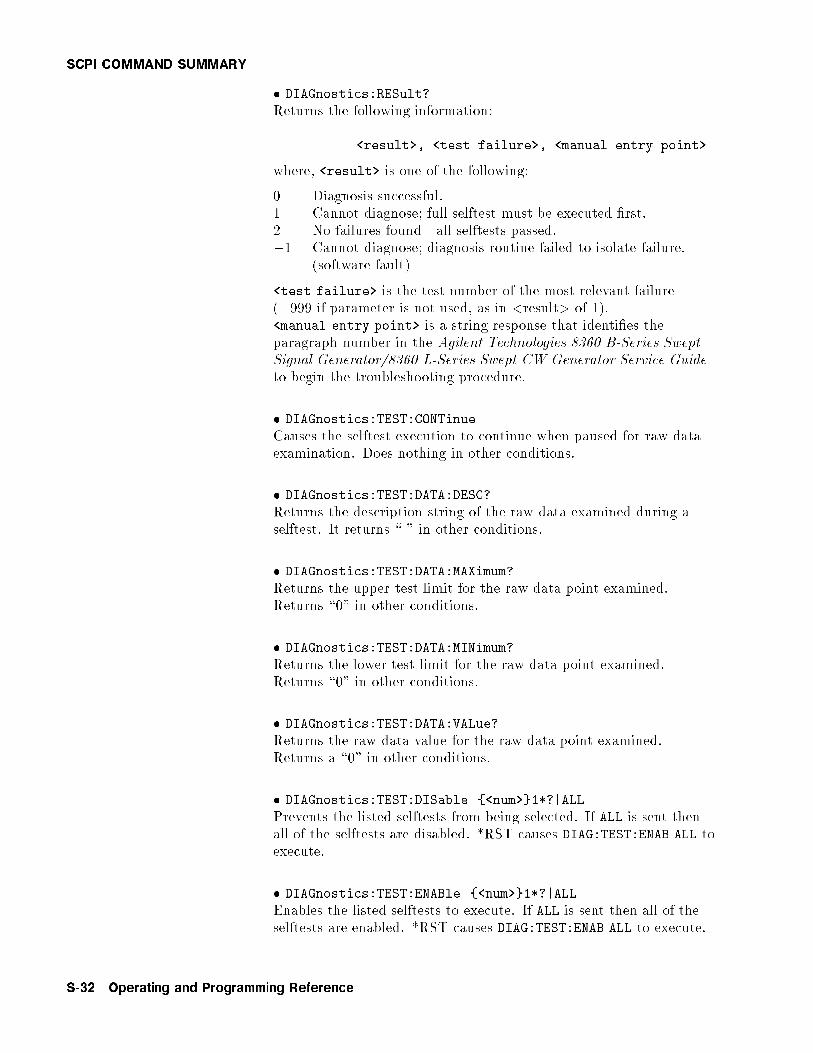
SCPI COMMAND SUMMARY
� DIAGnostics:RESult?
Returns the following information:
<result>, <test failure>, <manual entry point>
where, <result> is one of the following:
0 Diagnosis successful.1 Cannot diagnose; full selftest must be executed �rst.2 No failures found|all selftests passed.�1 Cannot diagnose; diagnosis routine failed to isolate failure.
(software fault)
<test failure> is the test number of the most relevant failure(�999 if parameter is not used, as in <result> of 1).<manual entry point> is a string response that identi�es theparagraph number in the Agilent Technologies 8360 B-Series SweptSignal Generator/8360 L-Series Swept CW Generator Service Guideto begin the troubleshooting procedure.
� DIAGnostics:TEST:CONTinue
Causes the selftest execution to continue when paused for raw dataexamination. Does nothing in other conditions.
� DIAGnostics:TEST:DATA:DESC?
Returns the description string of the raw data examined during aselftest. It returns \ " in other conditions.
� DIAGnostics:TEST:DATA:MAXimum?
Returns the upper test limit for the raw data point examined.Returns \0" in other conditions.
� DIAGnostics:TEST:DATA:MINimum?
Returns the lower test limit for the raw data point examined.Returns \0" in other conditions.
� DIAGnostics:TEST:DATA:VALue?
Returns the raw data value for the raw data point examined.Returns a \0" in other conditions.
� DIAGnostics:TEST:DISable {<num>}1*?|ALL
Prevents the listed selftests from being selected. If ALL is sent thenall of the selftests are disabled. *RST causes DIAG:TEST:ENAB ALL toexecute.
� DIAGnostics:TEST:ENABle {<num>}1*?|ALL
Enables the listed selftests to execute. If ALL is sent then all of theselftests are enabled. *RST causes DIAG:TEST:ENAB ALL to execute.
S-32 Operating and Programming Reference
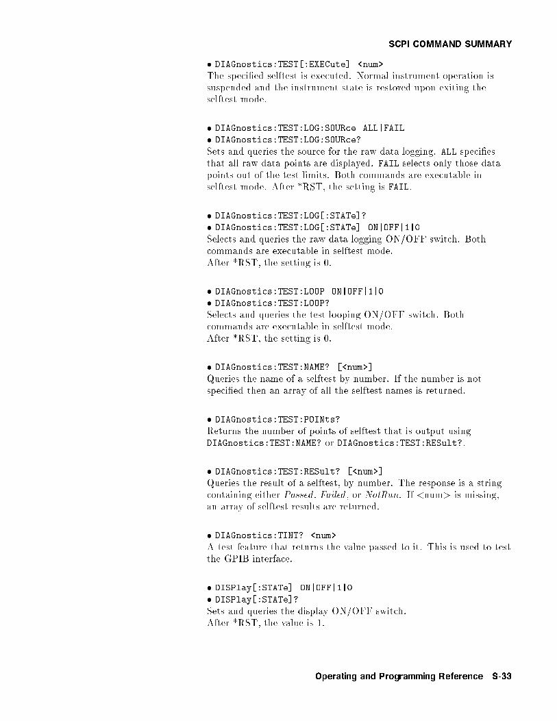
SCPI COMMAND SUMMARY
� DIAGnostics:TEST[:EXECute] <num>
The speci�ed selftest is executed. Normal instrument operation issuspended and the instrument state is restored upon exiting theselftest mode.
� DIAGnostics:TEST:LOG:SOURce ALL|FAIL
� DIAGnostics:TEST:LOG:SOURce?
Sets and queries the source for the raw data logging. ALL speci�esthat all raw data points are displayed. FAIL selects only those datapoints out of the test limits. Both commands are executable inselftest mode. After *RST, the setting is FAIL.
� DIAGnostics:TEST:LOG[:STATe]?
� DIAGnostics:TEST:LOG[:STATe] ON|OFF|1|0
Selects and queries the raw data logging ON/OFF switch. Bothcommands are executable in selftest mode.After *RST, the setting is 0.
� DIAGnostics:TEST:LOOP ON|OFF|1|0
� DIAGnostics:TEST:LOOP?
Selects and queries the test looping ON/OFF switch. Bothcommands are executable in selftest mode.After *RST, the setting is 0.
� DIAGnostics:TEST:NAME? [<num>]
Queries the name of a selftest by number. If the number is notspeci�ed then an array of all the selftest names is returned.
� DIAGnostics:TEST:POINts?
Returns the number of points of selftest that is output usingDIAGnostics:TEST:NAME? or DIAGnostics:TEST:RESult?.
� DIAGnostics:TEST:RESult? [<num>]
Queries the result of a selftest, by number. The response is a stringcontaining either Passed , Failed , or NotRun. If <num> is missing,an array of selftest results are returned.
� DIAGnostics:TINT? <num>
A test feature that returns the value passed to it. This is used to testthe GPIB interface.
� DISPlay[:STATe] ON|OFF|1|0
� DISPlay[:STATe]?
Sets and queries the display ON/OFF switch.After *RST, the value is 1.
Operating and Programming Reference S-33

SCPI COMMAND SUMMARY
� FM:COUPling AC|DC
� FM:COUPling?
Sets and queries the FM input coupling mode.The *RST value is AC.
� FM[:DEViation] <num>[freq suffix>]|MAXimum|MINimum
� FM[:DEViation]? [MAXimum|MINimum]
Sets and queries the peak FM deviation (in Hz) when the internalFM generator is used. After *RST, the value is 1 MHz.
� FM:FILTer:HPASs <num>[freq suffix'|MAXimum|MINimum
� FM:FILTer:HPASs? [MAXimum|MINimum]
Sets and queries the FM AC bandwidth. There are only twopositions to the bandwidth, < 20 Hz and > 100 kHz, but anynumeric is accepted. The value is compared to 1 kHz and the correctposition is determined (> 1 kHz sets the position to 100 kHz and� 1 kHz sets the position to 20 Hz). After *RST, the value is100 kHz.
� FM:INTernal:FREQuency <num>[freq suffix]|MAXimum|MINimum
� FM:INTernal:FREQuency? [MAXimum|MINimum]
Sets and queries the frequency (in Hz) of the internal FM source.After *RST, the value is 1 MHz.
� FM:INTernal:FUNCtion SINusoid|SQUare|TRIangle|RAMP|NOISe
� FM:INTernal:FUNCtion?
Sets and queries the waveform of the internal FM source.After *RST, the value is SINusoid.
� FM:SOURce INTernal|EXTernal
� FM:SOURce?
Sets and queries the source of the FM modulating signal.After *RST, the value is EXTernal.
� FM:SENSitivity <num>[freq suffix/V]|MAXimum|MINimum
� FM:SENSitivity? [MAXimum|MINimum]
Sets and queries the FM Input sensitivity.The *RST value is MAX (10 MHz/V) .
� FM:STATe ON|OFF|1|0
� FM:STATe?
Sets and queries the FM modulation state.After *RST, the value is OFF.
S-34 Operating and Programming Reference
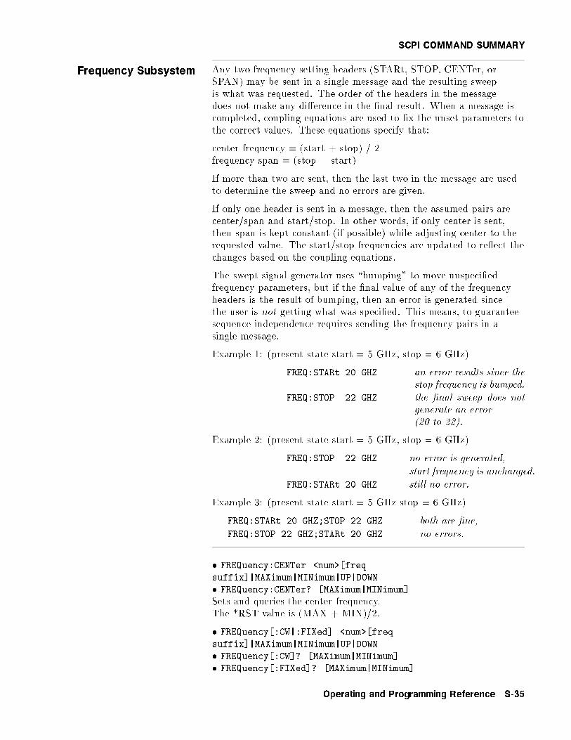
SCPI COMMAND SUMMARY
Frequency Subsystem Any two frequency setting headers (STARt, STOP, CENTer, orSPAN) may be sent in a single message and the resulting sweepis what was requested. The order of the headers in the messagedoes not make any di�erence in the �nal result. When a message iscompleted, coupling equations are used to �x the unset parameters tothe correct values. These equations specify that:
center frequency = (start + stop) / 2frequency span = (stop � start)
If more than two are sent, then the last two in the message are usedto determine the sweep and no errors are given.
If only one header is sent in a message, then the assumed pairs arecenter/span and start/stop. In other words, if only center is sent,then span is kept constant (if possible) while adjusting center to therequested value. The start/stop frequencies are updated to re ect thechanges based on the coupling equations.
The swept signal generator uses \bumping" to move unspeci�edfrequency parameters, but if the �nal value of any of the frequencyheaders is the result of bumping, then an error is generated sincethe user is not getting what was speci�ed. This means, to guaranteesequence independence requires sending the frequency pairs in asingle message.
Example 1: (present state start = 5 GHz, stop = 6 GHz)
FREQ:STARt 20 GHZ an error results since thestop frequency is bumped.
FREQ:STOP 22 GHZ the �nal sweep does notgenerate an error(20 to 22).
Example 2: (present state start = 5 GHz, stop = 6 GHz)
FREQ:STOP 22 GHZ no error is generated,
start frequency is unchanged.
FREQ:STARt 20 GHZ still no error.
Example 3: (present state start = 5 GHz stop = 6 GHz)
FREQ:STARt 20 GHZ;STOP 22 GHZ both are �ne,
FREQ:STOP 22 GHZ;STARt 20 GHZ no errors.
� FREQuency:CENTer <num>[freq
suffix]|MAXimum|MINimum|UP|DOWN
� FREQuency:CENTer? [MAXimum|MINimum]
Sets and queries the center frequency.The *RST value is (MAX + MIN)/2.
� FREQuency[:CW|:FIXed] <num>[freq
suffix]|MAXimum|MINimum|UP|DOWN
� FREQuency[:CW]? [MAXimum|MINimum]
� FREQuency[:FIXed]? [MAXimum|MINimum]
Operating and Programming Reference S-35
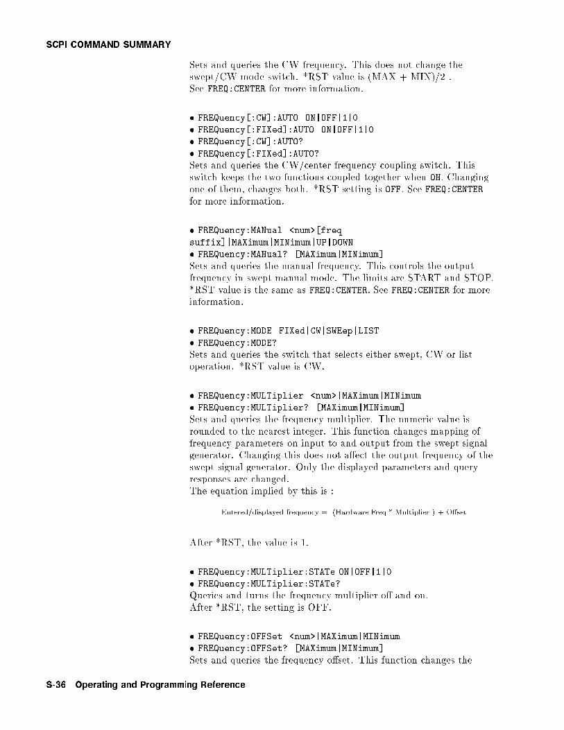
SCPI COMMAND SUMMARY
Sets and queries the CW frequency. This does not change theswept/CW mode switch. *RST value is (MAX + MIN)/2 .See FREQ:CENTER for more information.
� FREQuency[:CW]:AUTO ON|OFF|1|0
� FREQuency[:FIXed]:AUTO ON|OFF|1|0
� FREQuency[:CW]:AUTO?
� FREQuency[:FIXed]:AUTO?
Sets and queries the CW/center frequency coupling switch. Thisswitch keeps the two functions coupled together when ON. Changingone of them, changes both. *RST setting is OFF. See FREQ:CENTERfor more information.
� FREQuency:MANual <num>[freq
suffix]|MAXimum|MINimum|UP|DOWN
� FREQuency:MANual? [MAXimum|MINimum]
Sets and queries the manual frequency. This controls the outputfrequency in swept manual mode. The limits are START and STOP.*RST value is the same as FREQ:CENTER. See FREQ:CENTER for moreinformation.
� FREQuency:MODE FIXed|CW|SWEep|LIST
� FREQuency:MODE?
Sets and queries the switch that selects either swept, CW or listoperation. *RST value is CW.
� FREQuency:MULTiplier <num>|MAXimum|MINimum
� FREQuency:MULTiplier? [MAXimum|MINimum]
Sets and queries the frequency multiplier. The numeric value isrounded to the nearest integer. This function changes mapping offrequency parameters on input to and output from the swept signalgenerator. Changing this does not a�ect the output frequency of theswept signal generator. Only the displayed parameters and queryresponses are changed.The equation implied by this is :
Entered/displayed frequency = (Hardware Freq * Multiplier ) + O�set
After *RST, the value is 1.
� FREQuency:MULTiplier:STATe ON|OFF|1|0
� FREQuency:MULTiplier:STATe?
Queries and turns the frequency multiplier o� and on.After *RST, the setting is OFF.
� FREQuency:OFFSet <num>|MAXimum|MINimum
� FREQuency:OFFSet? [MAXimum|MINimum]
Sets and queries the frequency o�set. This function changes the
S-36 Operating and Programming Reference

SCPI COMMAND SUMMARY
mapping of the frequency parameters on input to and output fromthe swept signal generator. Changing this does not a�ect theoutput frequency of the swept signal generator. Only the displayedparameters and query responses are changed. The equation impliedby this is :
Entered/displayed frequency = (Hardware Freq * Multiplier ) + O�set
After *RST, the value is 0.
� FREQuency:OFFSet:STATe ON|OFF|1|0
� FREQuency:OFFSet:STATe?
Queries and turns the frequency o�set o� and on.After *RST, the setting is OFF.
� FREQuency:SPAN <num>[freq
suffix]|MAXimum|MINimum|UP|DOWN
� FREQuency:SPAN? [MAXimum|MINimum]
Sets and queries the frequency span. See FREQ:CENTER for moreinformation.
� FREQuency:STARt <num>[freq suffix]
|MAXimum|MINimum|UP|DOWN
� FREQuency:STARt? [MAXimum|MINimum]
Sets and queries the START Frequency. See FREQ:CENTER for moreinformation. *RST setting is MIN.
� FREQuency:STEP:AUTO ON|OFF|1|0
� FREQuency:STEP:AUTO?
Sets and queries the function switch that controls the calculation ofthe frequency step size (FREQ:STEP:INCR). If the response isAUTO ON, then the swept signal generator selects a step size that iscoupled to the frequency span. The *RST setting is ON.
� FREQuency:STEP[:INCRement] <num>[freq
suffix]|MAXimum|MINimum
� FREQuency:STEP[:INCRement]?
Sets and queries the frequency step size to use for any node in thefrequency subsystem that allows UP and DOWN as parameters. Settingthis value explicitly causes a FREQ:STEP:AUTO OFF command.The *RST setting is automatically calculated from span.
� FREQuency:STOP <num>[freq
suffix]|MAXimum|MINimum|UP|DOWN
� FREQuency:STOP? [MAXimum|MINimum]
Sets and queries the stop Frequency. See FREQ:CENTER for moreinformation. *RST setting is MAX.
Operating and Programming Reference S-37
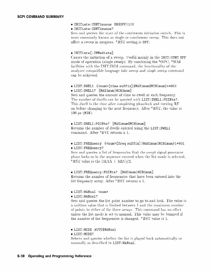
SCPI COMMAND SUMMARY
� INITiate:CONTinuous ON|OFF|1|0
� INITiate:CONTinuous?
Sets and queries the state of the continuous initiation switch. This ismore commonly known as single or continuous sweep. This does nota�ect a sweep in progress. *RST setting is OFF.
� INITiate[:IMMediate]
Causes the initiation of a sweep. Useful mainly in the INIT:CONT OFF
mode of operation (single sweep). By combining the *OPC, *WAIfacilities with the INIT:IMM command, the functionality of theanalyzer compatible language take sweep and single sweep commandcan be achieved.
� LIST:DWELl {<num>[time suffix]|MAXimum|MINimum}1*801
� LIST:DWELl? [MAXimum|MINimum]
Sets and queries the amount of time to dwell at each frequency.The number of dwells can be queried with LIST:DWELl:POINts?.This dwell is the time after completing phaselock and turning RFon before changing to the next frequency. After *RST, the value is100 �s (MIN).
� LIST:DWELl:POINts? [MAXimum|MINimum]
Returns the number of dwells entered using the LIST:DWELlcommand. After *RST returns a 1.
� LIST:FREQuency {<num>[freq suffix]|MAXimum|MINimum}1*801
� LIST:FREQuency?
Sets and queries a list of frequencies that the swept signal generatorphase locks to in the sequence entered when the list mode is selected.*RST value is the (MAX + MIN)/2.
� LIST:FREQuency:POINts? [MAXimum|MINimum]
Returns the number of frequencies that have been entered into thelist frequency array. After *RST returns a 1.
� LIST:MANual <num>
� LIST:MANual?
Sets and queries the list point number to go to and lock. The value isa unitless value that is limited between 1 and the maximum numberof points in either of the three arrays. This command has no e�ectunless the list mode is set to manual. This value may be bumped ifthe number of list frequencies is changed. *RST value is 1.
� LIST:MODE AUTO|MANual
� LIST:MODE?
Selects and queries whether the list is played back automatically ormanually as described in LIST:MANual.
S-38 Operating and Programming Reference
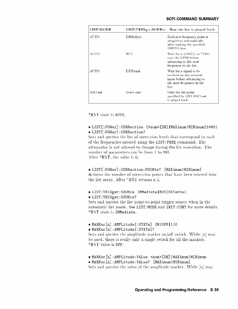
SCPI COMMAND SUMMARY
LIST:MODE LIST:TRIGger:SOURce How the list is played back.
AUTO IMMediate Each new frequency point isstepped to automatically,after waiting the speci�edDWELl time.
AUTO BUS Wait for a <GET> or *TRGover the GPIB beforeadvancing to the nextfrequency in the list.
AUTO EXTernal Wait for a signal to bereceived on the externalinput before advancing tothe next frequency in thelist.
MANual Don't care Only the list pointspeci�ed by LIST:MANualis played back.
*RST state is AUTO.
� LIST[:POWer]:CORRection {<num>[DB]|MAXimum|MINimum}1*801
� LIST[:POWer]:CORRection?
Sets and queries the list of correction levels that correspond to eachof the frequencies entered using the LIST:FREQ command. Theattenuator is not allowed to change during the list execution. Thenumber of parameters can be from 1 to 801.After *RST, the value is 0.
� LIST[:POWer]:CORRection:POINts? [MAXimum|MINimum]
Returns the number of correction points that have been entered intothe list array. After *RST returns a 1.
� LIST:TRIGger:SOURce IMMediate|BUS|EXTernal
� LIST:TRIGger:SOURce?Sets and queries the list point-to-point trigger source when in theautomatic list mode. See LIST:MODE and INIT:CONT for more details.*RST state is IMMediate.
� MARKer[n]:AMPLitude[:STATe] ON|OFF|1|0
� MARKer[n]:AMPLitude[:STATe]?
Sets and queries the amplitude marker on/o� switch. While [n] maybe used, there is really only a single switch for all the markers.*RST value is OFF.
� MARKer[n]:AMPLitude:VALue <num>[DB]|MAXimum|MINimum
� MARKer[n]:AMPLitude:VALue? [MAXimum|MINimum]
Sets and queries the value of the amplitude marker. While [n] may
Operating and Programming Reference S-39

SCPI COMMAND SUMMARY
be used, there is really only a single value for all the markers.*RST value is 2 dB.
� MARKer[n]:AOFF
Sets all the markers to OFF at once. While [n] may be used, there isreally only a single switch for all the markers.
� MARKer[n]:DELTa? <num>,<num>
This query returns the di�erence in frequency between the twospeci�ed marker numbers.
� MARKer[n]:FREQuency <num>[freq suffix]|MAXimum|MINimum
� MARKer[n]:FREQuency? [MAXimum|MINimum]
Sets and queries the speci�ed marker frequency (marker numberone is the default if [n] is not speci�ed). The value is interpreteddi�erently based on the value of the marker mode.
MARKer[n]:MODE How the frequency of the marker is determined.
FREQuency Absolute frequency is used. The limits arecon�ned to the present START and STOPfrequency limits.
DELTa The value is speci�ed with respect to thereference marker. (MARKer[n]:REFerence)
The *RST values are the same as the FREQ:CENTcommand *RSTvalue.
� MARKer[n]:MODE FREQuency|DELTa
� MARKer[n]:MODE?
Sets and queries the mode of the speci�ed marker. Setting onemarker to delta turns all other marker modes to frequency. If [n] isnot speci�ed, the default is one. *RST value is FREQuency.
� MARKer[n]:REFerence <n>
� MARKer[n]:REFerence?Sets and queries which marker is the reference marker for use inthe delta mode. While [n] may be used, there is really only asingle reference for all the markers. MARKer1:REFerence 5; andMARKer2:REFerence 5; both set marker 5 as the reference.
� MARKer[n][:STATe] ON|OFF|1|0
� MARKer[n][:STATe]?
The state of the speci�ed marker is set and queried (marker numberone if [n] is not speci�ed). The *RST value for all markers is OFF.
� MEASure:AM?
A query-only command that causes the modulating AM signal to be
S-40 Operating and Programming Reference
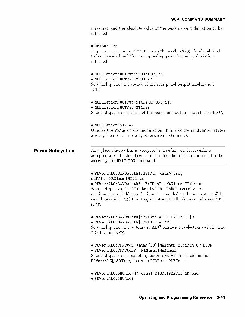
SCPI COMMAND SUMMARY
measured and the absolute value of the peak percent deviation to bereturned.
� MEASure:FM
A query-only command that causes the modulating FM signal levelto be measured and the corresponding peak frequency deviationreturned.
� MODulation:OUTPut:SOURce AM|FM
� MODulation:OUTPut:SOURce?
Sets and queries the source of the rear panel output modulationBNC.
� MODulation:OUTPut:STATe ON|OFF|1|0
� MODulation:OUTPut:STATe?
Sets and queries the state of the rear panel output modulation BNC.
� MODulation:STATe?
Queries the status of any modulation. If any of the modulation statesare on, then it returns a 1, otherwise it returns a 0.
Power Subsystem Any place where dBm is accepted as a su�x, any level su�x isaccepted also. In the absence of a su�x, the units are assumed to beas set by the UNIT:POW command.
� POWer:ALC:BANDwidth|:BWIDth <num>[freq
suffix]|MAXimum|MINimum
� POWer:ALC:BANDwidth?|:BWIDth? [MAXimum|MINimum]
Sets and queries the ALC bandwidth. This is actually notcontinuously variable, so the input is rounded to the nearest possibleswitch position. *RST setting is automatically determined since AUTOis ON.
� POWer:ALC:BANDwidth|:BWIDth:AUTO ON|OFF|1|0
� POWer:ALC:BANDwidth|:BWIDth:AUTO?
Sets and queries the automatic ALC bandwidth selection switch. The*RST value is ON.
� POWer:ALC:CFACtor <num>[DB]|MAXimum|MINimum|UP|DOWN
� POWer:ALC:CFACtor? [MINimum|MAXimum]
Sets and queries the coupling factor used when the commandPOWer:ALC[:SOURce] is set to DIODe or PMETer.
� POWer:ALC:SOURce INTernal|DIODe|PMETer|MMHead
� POWer:ALC:SOURce?
Operating and Programming Reference S-41

SCPI COMMAND SUMMARY
Sets and queries the ALC leveling source selection switch.The *RST value is INTernal.
� POWer:ALC[:STATe] ON|OFF|1|0
� POWer:ALC[:STATe]?
Sets and queries the state switch of the ALC. The positions are :ON|normal ALC operationOFF|open loop ALC mode
When on, the power can be programmed in fundamental units asselected by the UNIT:POWer command.
When o�, the power is no longer calibrated in absolute units and isset in units of dB of arbitrary modulator setting.
� POWer:AMPLifier:STATE ON|OFF|0|1
� POWer:AMPLifier:STATE?
Sets and queries the state of the ampli�er contained inthe doubler (for those models with a doubler installed).Programming a speci�c value for POWer:AMPLifier:STATE setsPOWer:AMPLifier:STATE:AUTO to OFF.
� POWer:AMPLifier:STATE:AUTO ON|OFF|0|1
� POWer:AMPLifier:STATE:AUTO?
Sets and queries the automatic selection of the doubler ampli�erstate. Programming a speci�c value for POWer:AMPLifier:STATE setsPOWer:AMPLifier:STATE:AUTO to OFF. *RST value is ON.
� POWer:ATTenuation <num>[DB]|MAXimum|MINimum|UP|DOWN
� POWer:ATTenuation? [MAXimum|MINimum]
Sets and queries the output attenuation level. Note that whensetting the attenuator level to 10 dB, the output power isdecreased by 10 dB. Programming a speci�ed attenuation setsPOWer:ATTenuation:AUTO OFF.
� POWer:ATTenuation:AUTO ON|OFF|1|0
� POWer:ATTenuation:AUTO?
Sets and queries the state of the RF attenuator coupling switch.Programming a speci�ed attenuation setsPOWer:ATTenuation:AUTO OFF.ON - insures that the amplitude level of the ALC is kept withinoptimal limits.OFF - the attenuator setting is set to the value of POW:ATT and leftthere. The *RST value is ON.
� POWer:CENTer <num> [lvl suffix]|MAXimum|MINimum|UP|DOWN
� POWer:CENTer? [MAXimum|MINimum]
Sets and queries the center power for power sweep. Default units(and units for query response) are determined by the UNIT:POWercommand.
S-42 Operating and Programming Reference

SCPI COMMAND SUMMARY
The coupling equations for power sweep are exactly analogous tothose for frequency sweep. Power sweep is allowed to be negative,unlike frequency sweeps. See FREQ:CENT for a description. *RSTvalue is 0 dBm.
� POWer[:LEVel] <num>[lvl suffix]|MAXimum|MINimum|UP|DOWN
� POWer[:LEVel]? [MAXimum|MINimum]
Sets and queries the output level. Default units and unitsfor the query response are determined by the UNIT:POWercommand. Maximum and minimum levels refer to theleveling mode at the time the command is sent. For example,*RST;POWer:LEVel MIN; ALC:SOURce MMHead has di�erent e�ectsfrom *RST;POWer:ALC:SOURce MMHead; POWer:LEVel MIN
After *RST, the value is 0 dBm.
� POWer:MODE FIXed|SWEep
� POWer:MODE?
Sets and queries the setting of the power sweep mode switch. If inthe sweep mode then the output level is controlled by the start,stop, center and span functions. If in the �xed power mode then theoutput is controlled by the POW[:LEVEL] command. The *RST valueis FIXed.
� POWer:OFFSet <num>[DB]|MAXimum|MINimum|UP|DOWN
� POWer:OFFSet? [MAXimum|MINimum]
Sets and queries the power o�set. This function changes mapping ofabsolute power parameters on input to and output from the sweptsignal generator. Changing this does not a�ect the output power ofthe swept signal generator. Only the displayed parameters and queryresponses are changed. The equation implied by this is:The entered or displayed power = Hardware Power + O�set After*RST, the value is 0.
� POWer:OFFSet:STATe ON|OFF|1|0
� POWer:OFFSet:STATe?
Queries and turns the power o�set o� and on. After *RST, thesetting is OFF.
� POWer:RANGe <num>[lvl suffix]|MAXimum|MINimum|UP|DOWN
� POWer:RANGe?
Sets and queries the setting of the power meter range. This is usedwhen the command POWer:ALC:SOURce is set to PMETer.
� POWer:SEARch ON|OFF|1|0|ONCE
� POWer:SEARch?
Sets and queries the power search switch. This has an interactionwith POWer:ALC:STATe as described below.
Operating and Programming Reference S-43
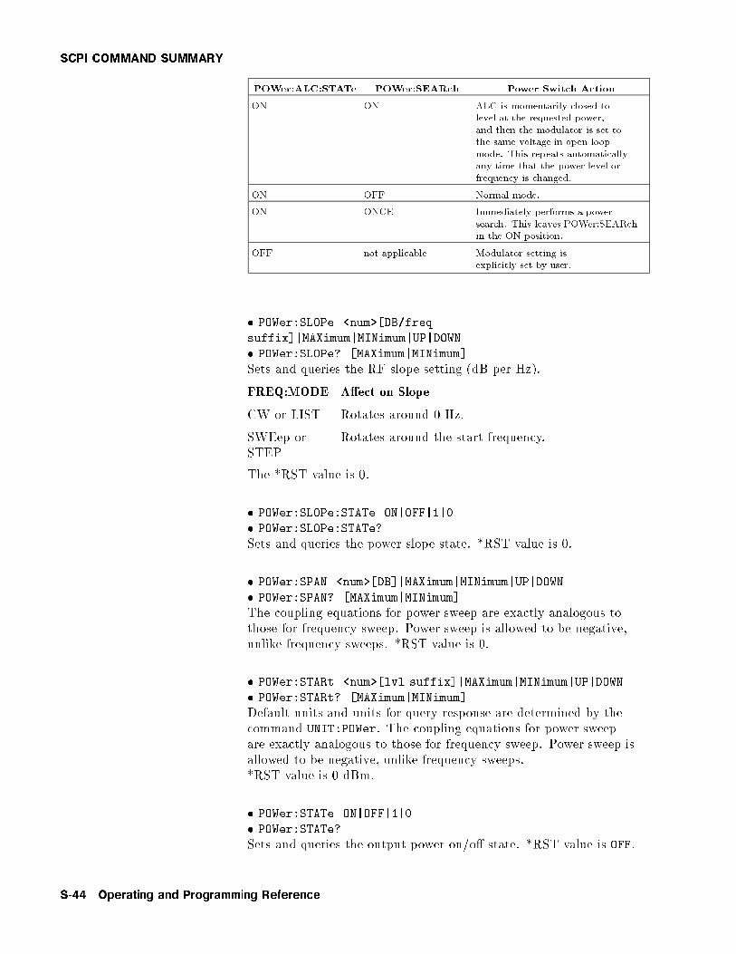
SCPI COMMAND SUMMARY
POWer:ALC:STATe POWer:SEARch Power Switch Action
ON ON ALC is momentarily closed tolevel at the requested power,and then the modulator is set tothe same voltage in open loopmode. This repeats automaticallyany time that the power level orfrequency is changed.
ON OFF Normal mode.
ON ONCE Immediately performs a powersearch. This leaves POWer:SEARchin the ON position.
OFF not applicable Modulator setting isexplicitly set by user.
� POWer:SLOPe <num>[DB/freq
suffix]|MAXimum|MINimum|UP|DOWN
� POWer:SLOPe? [MAXimum|MINimum]
Sets and queries the RF slope setting (dB per Hz).
FREQ:MODE A�ect on Slope
CW or LIST Rotates around 0 Hz.
SWEep orSTEP
Rotates around the start frequency.
The *RST value is 0.
� POWer:SLOPe:STATe ON|OFF|1|0
� POWer:SLOPe:STATe?
Sets and queries the power slope state. *RST value is 0.
� POWer:SPAN <num>[DB]|MAXimum|MINimum|UP|DOWN
� POWer:SPAN? [MAXimum|MINimum]
The coupling equations for power sweep are exactly analogous tothose for frequency sweep. Power sweep is allowed to be negative,unlike frequency sweeps. *RST value is 0.
� POWer:STARt <num>[lvl suffix]|MAXimum|MINimum|UP|DOWN
� POWer:STARt? [MAXimum|MINimum]
Default units and units for query response are determined by thecommand UNIT:POWer. The coupling equations for power sweepare exactly analogous to those for frequency sweep. Power sweep isallowed to be negative, unlike frequency sweeps.*RST value is 0 dBm.
� POWer:STATe ON|OFF|1|0
� POWer:STATe?
Sets and queries the output power on/o� state. *RST value is OFF.
S-44 Operating and Programming Reference
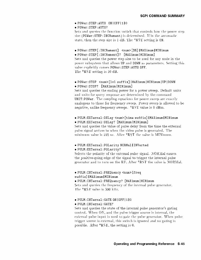
SCPI COMMAND SUMMARY
� POWer:STEP:AUTO ON|OFF|1|0
� POWer:STEP:AUTO?
Sets and queries the function switch that controls how the power stepsize (POWer:STEP:INCRement) is determined. If in the automaticstate, then the step size is 1 dB. The *RST setting is ON.
� POWer:STEP[:INCRement] <num>[DB]|MAXimum|MINimum
� POWer:STEP[:INCRement]? [MAXimum|MINimum]
Sets and queries the power step size to be used for any node in thepower subsystem that allows UP and DOWN as parameters. Setting thisvalue explicitly causes POWer:STEP:AUTO OFF.The *RST setting is 10 dB.
� POWer:STOP <num>[lvl suffix]|MAXimum|MINimum|UP|DOWN
� POWer:STOP? [MAXimum|MINimum]
Sets and queries the ending power for a power sweep. Default unitsand units for query response are determined by the commandUNIT:POWer. The coupling equations for power sweep are exactlyanalogous to those for frequency sweep. Power sweep is allowed to benegative, unlike frequency sweeps. *RST value is 0 dBm.
� PULM:EXTernal:DELay <num>[time suffix]|MAXimum|MINimum
� PULM:EXTernal:DELay? [MAXimum|MINimum]
Sets and queries the value of pulse delay from the time the externalpulse signal arrives to when the video pulse is generated. Theminimum value is 225 ns. After *RST the value is MINimum.
� PULM:EXTernal:POLarity NORMal|INVerted
� PULM:EXTernal:POLarity?
Selects the polarity of the external pulse signal. NORMal causesthe positive-going edge of the signal to trigger the internal pulsegenerator and to turn on the RF. After *RST the value is NORMal.
� PULM:INTernal:FREQuency <num>[freq
suffix]|MAXimum|MINimum
� PULM:INTernal:FREQuency? [MAXimum|MINimumSets and queries the frequency of the internal pulse generator.The *RST value is 500 kHz.
� PULM:INTernal:GATE ON|OFF|1|0
� PULM:INTernal:GATE?
Sets and queries the state of the internal pulse generator's gatingcontrol. When ON, and the pulse trigger source is internal, theexternal pulse input is used to gate the pulse generator. When pulsetrigger source is external, this switch is ignored and no gating ispossible. After *RST, the setting is 0.
Operating and Programming Reference S-45

SCPI COMMAND SUMMARY
� PULM:INTernal:PERiod <num>[time suffix]|MAXimum|MINimum
� PULM:INTernal:PERiod? {MAXimum|MINimum]
Sets and queries the period of the internal pulse generator.The *RST value is 2 �s.
� PULM:INTernal:TRIGger:SOURce INTernal|EXTernal
� PULM:INTernal:TRIGger:SOURce? [MAXimum|MINimum]
Sets and queries the setting of the internal pulse generator's triggersource. When INTernal, pulse period and frequency determine therepetition rate of the pulse train. When in EXTernal, the repetitionrate is set by the EXT PULSE in jack. After *RST, the value isINTernal.
� PULM:INTernal:WIDTH <num>{time suffix]|MAXimum|MINimum
� PULM:INTernal:WIDTH? [MAXimum|MINimum]
Sets and queries the width of the internal pulse generator. The *RSTvalue is 1 �s.
Pulse Subsystem Since frequency and period are inversely related, if both are sentin the same message, only the last one is applied. If the WIDthcommand and either the FREQuency or PERiod command are sentin the same message, they must be accepted without error if theresulting pulse is possible.
� PULSe:FREQuency <num>[freq suffix]|MAXimum|MINimum
� PULSe:FREQuency? [MAXimum|MINimum]
Sets and queries the frequency of the internal pulse generator. Theresolution of the frequency is such that the resulting period is set to aresolution of 1 �s. The *RST value is 500 kHz.
� PULSe:PERiod <num>[time suffix]|MAXimum|MINimum
� PULSe:PERiod? [MAXimum|MINimum]
Sets and queries the period of the internal pulse generator. Theresolution of this is 1 �s. The *RST value is 2 �s.
� PULSe:WIDTh <num>[time suffix]|MAXimum|MINimum
� PULSe:WIDTh? [MAXimum|MINimum]
Sets and queries the width of the internal pulse generator. The *RSTvalue is 1 �s.
� PULM:SLEW <num>[time suffix]|MAXimum|MINimum
� PULM:SLEW? [MAXimum|MINimum]
Sets and queries the rise time for the pulse modulation. The typicalusage is MAX|MIN since calibrating the rise time of the pulses is notcommon. Slow pulse is set by the command PULS:SLEW MAX. Anyvalue above 1.8 �s is set to maximum. The *RST setting is MIN.
S-46 Operating and Programming Reference

SCPI COMMAND SUMMARY
� PULM:SLEW:AUTO ON|OFF|1|0
� PULM:SLEW:AUTO?
Sets and queries the automatic setting of rise time for the pulsemodulation system. The *RST setting is ON.
� PULM:SOURce INTernal|EXTernal|SCALar
� PULM:SOURce?
Sets and queries the source for the pulse modulation control signal.*RST value is INTernal.
� PULM:STATe ON|OFF|1|0
� PULM:STATe?
Sets and queries the state of pulse modulation. The *RST value is 0.
� ROSCillator:SOURce?
� ROSCillator:SOURce INTernal|EXTernal|NONE
Sets and queries the reference oscillator selection switch. Thecommand to set the switch will cause ROSC:SOUR:AUTO OFF tobe done also. The *RST value is automatically determined.
� ROSCillator:SOURce:AUTO ON|OFF|1|0
� ROSCillator:SOURce:AUTO?
Sets and queries the automatic reference selection switch.The *RST value is 1.
� STATus:OPERation:CONDition?
Queries the Standard Operation Condition register.
� STATus:OPERation:ENABle <num>
� STATus:OPERation:ENABle?
Sets and queries the Standard Operation Enable register.The STATus:PRESet value is 0.
� STATus:OPERation[:EVENt]?
Queries the Standard Operation Event Register. This is a destructiveread.
� STATus:OPERation:NTRansition <num>
� STATus:OPERation:NTRansition?
Sets and queries the Standard Operation Negative Transition Filter.The STATus:PRESet value is 0.
� STATus:OPERation:PTRansition <num>
� STATus:OPERation:PTRansition?
Sets and queries the Standard Operation Positive Transition Filter.After STATus:PRESet, all used bits are set to 1s.
Operating and Programming Reference S-47
SCPI COMMAND SUMMARY
� STATUS:PRESet
This command presets the following enable and transition registers:MSIB, OPERation, QUEStionable, and SRECeiver.
ENABle Is set to all 0s.
NTRansition Is set to all 0s.
PTRansition All bits used are set to 1s. Unused bits remain 0s.
� STATus:QUEStionable:CONDition?
Queries the Data Questionable Condition Register.
� STATus:QUEStionable:ENABle <num>
� STATus:QUEStionable:ENABle?
Sets and queries the Data Questionable SRQ Enable register.The STATus:PRESet value is 0.
� STATus:QUEStionable[:EVENt]?
Queries the Data Questionable Event Register. This is a destructiveread.
� STATus:QUEStionable:NTRansition <num>
� STATus:QUEStionable:NTRansition?
Sets and queries the Negative TRansition Filter for the DataQuestionable Status Register. The STATus:PRESet value is 0.
� STATus:QUEStionable:PTRansition <num>
� STATus:QUEStionable:PTRansition?
Sets and queries the Positive TRansition Filter for the DataQuestionable Status Register. After STATus:PRESet, all used bits areset to 1s.
S-48 Operating and Programming Reference
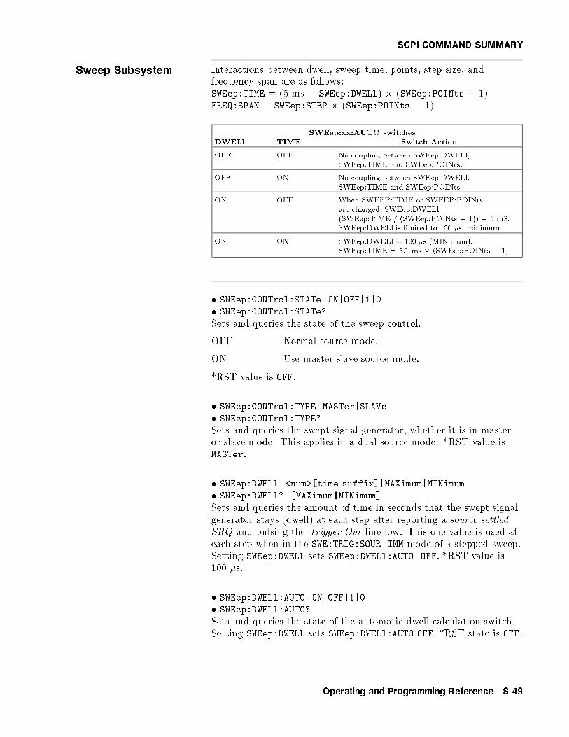
SCPI COMMAND SUMMARY
Sweep Subsystem Interactions between dwell, sweep time, points, step size, andfrequency span are as follows:SWEep:TIME = (5 ms + SWEep:DWELl) � (SWEep:POINts � 1)FREQ:SPAN = SWEep:STEP � (SWEep:POINts � 1)
SWEep:xx:AUTO switches
DWELl TIME Switch Action
OFF OFF No coupling between SWEep:DWELl,SWEep:TIME and SWEep:POINts.
OFF ON No coupling between SWEep:DWELl,SWEep:TIME and SWEep:POINts.
ON OFF When SWEEP:TIME or SWEEP:POINtsare changed, SWEep:DWELl =(SWEep:TIME / (SWEep:POINts � 1)) � 5 mS.SWEep:DWELl is limited to 100 �s, minimum.
ON ON SWEep:DWELl = 100 �s (MINimum).SWEep:TIME = 5.1 ms � (SWEep:POINts � 1)
� SWEep:CONTrol:STATe ON|OFF|1|0
� SWEep:CONTrol:STATe?
Sets and queries the state of the sweep control.
OFF Normal source mode.
ON Use master slave source mode.
*RST value is OFF.
� SWEep:CONTrol:TYPE MASTer|SLAVe
� SWEep:CONTrol:TYPE?
Sets and queries the swept signal generator, whether it is in masteror slave mode. This applies in a dual source mode. *RST value isMASTer.
� SWEep:DWELl <num>[time suffix]|MAXimum|MINimum
� SWEep:DWELl? [MAXimum|MINimum]
Sets and queries the amount of time in seconds that the swept signalgenerator stays (dwell) at each step after reporting a source settledSRQ and pulsing the Trigger Out line low. This one value is used ateach step when in the SWE:TRIG:SOUR IMM mode of a stepped sweep.Setting SWEep:DWELL sets SWEep:DWELl:AUTO OFF. *RST value is100 �s.
� SWEep:DWELl:AUTO ON|OFF|1|0
� SWEep:DWELl:AUTO?
Sets and queries the state of the automatic dwell calculation switch.Setting SWEep:DWELL sets SWEep:DWELl:AUTO OFF. *RST state is OFF.
Operating and Programming Reference S-49

SCPI COMMAND SUMMARY
Combining the Sweep Mode With the Sweep Generation Command
to Obtain the Desired Sweep Condition
Description of
Sweep Condition
:FREQ :POW :SWE :LIST :SWE
:MODE :MODE :MODE :MODE :GEN
CW Non-swept CW FIX ignored ignored ignored
Analog freq sweep SWE FIX AUTO ignored ANAL
Manual analog freq sweep SWE FIX MAN ignored ANAL
Stepped freq sweep SWE FIX AUTO ignored STEP
Manual step freq sweep SWE FIX MAN ignored STEP
CW with analog powersweep
CW SWE AUTO ignored ANAL
CW with manual analogpower sweep
CW SWE MAN ignored ANAL
CW with stepped powersweep
CW SWE AUTO ignored STEP
CW with manual steppedpower sweep
CW SWE MAN ignored STEP
Analog frequency andpower sweep
SWE SWE AUTO ignored ANAL
Manual analog frequencyand power sweep
SWE SWE MAN ignored ANAL
Stepped frequency andpower sweep
SWE SWE AUTO ignored STEP
Manual stepped frequencyand power sweep
SWE SWE MAN ignored STEP
List sweep LIST ignored ignored AUTO ignored
Manual list sweep LIST ignored ignored MAN ignored
� SWEep:GENeration STEPped|ANALog
� SWEep:GENeration?
Sets and queries the type of sweep to be generated: an analog sweepor a digitally stepped sweep. In either case, all of the other sweepsubsystem functions apply. *RST is ANALog.
� SWEep:MANual:POINt <num>|MAXimum|MINimum
� SWEep:MANual:POINt? [MAXimum|MINimum]
Sets and queries the step point number to go to and lock. The valueis a unitless value that is limited between 1 and the number of pointsrequested. This command has no e�ect on the instrument unless:the sweep mode is set to manual and the sweep generation is set tostepped mode. *RST value is 1.
� SWEep:MANual[:RELative] <num>
� SWEep:MANual[:RELative]?
Sets and queries a percent of sweep to go to and lock. This commandhas no e�ect unless: the sweep mode is set to manual and the sweepgeneration is set to analog. *RST value is 0.50.
S-50 Operating and Programming Reference
SCPI COMMAND SUMMARY
� SWEep:MARKer:STATe ON|OFF|1|0
� SWEep:MARKer:STATe?
Sets and queries the state of marker sweep. When ON, the frequencysweep limits are taken to be the positions of marker 1 and marker 2.*RST value is 0.
� SWEep:MARKer:XFER
This transfers the values of marker 1 and marker 2 frequencies intostart and stop frequency.
� SWEep:MODE AUTO|MANual
� SWEep:MODE?
Selects and queries the manual sweep mode switch.
AUTO The sweep is under the control of the INIT andSWEEP subsystems.
MANual FREQ:MANual, SWEep:MANual[:RELative], andSWEep:MANual:POINt control the output.
*RST value is AUTO.
� SWEep:POINts <num>|MAXimum|MINimum
� SWEep:POINts? [MAXimum|MINimum]
Sets and queries the number of points in a step sweep. When pointsis changed, SWEep:STEP is modi�ed by the equationSTEP = SPAN/POINTS.Span is normally an independent variable but is changed to STEP� POINTS if both of these parameters are changed in the samemessage. *RST value is 11.
� SWEep:STEP <num>[freq suffix]|MAXimum|MINimum
� SWEep:STEP? [MAXimum|MINimum]
Sets and queries the size of each frequency step. :STEP is governedby the equationSTEP = SPAN/POINTS.
If you change step size then the number of points will be changedto span/step and a Parameter Bumped execution error is reported.If span or points are changed, then STEP= SPAN/POINTS. Thestep sweep command creates a coupling with sweeptime also.If the number of points is changed through this coupling andDWELl:AUTO is ON and TIME:AUTO is ON, then dwell is changed toSWEEPTIME/POINTS. Span is normally an independent variablebut is changed to STEP � POINTS if both of these parameters arechanged in the same message. *RST value is StopMax-StartMin/10.
� SWEep:TIME <num>[time suffix]|MAXimum|MINimum
� SWEep:TIME? [MAXimum|MINimum]
Sets and queries the current sweep time. The dwell time can becoupled to sweep time if SWE:DWEL:AUTO is ON. The dwell time is
Operating and Programming Reference S-51

SCPI COMMAND SUMMARY
then governed by the equation DWELl = SWEEPTIME/POINTS.Changing either sweep time or the number of points causes DWELlto be recalculated but does not cause an error. If you attempt tochange the dwell time then :AUTO is set to OFF. If DWELl:AUTO is OFFthen sweep time is independent of the dwell time and the number ofpoints. *RST value is MIN.
� SWEep:TIME:AUTO ON|OFF|1|0
� SWEep:TIME:AUTO?
Sets and queries the automatic sweep time switch.
ON The value of the sweep time is automatically tominimum.
OFF Attempting to set a sweep time faster than allowedin the AUTO mode causes this switch to change toAUTO ON even if it was previously in the AUTO OFF
mode.
*RST state is ON.
� SWEep:TIME:LLIMit <num>[time suffix]|MAXimum|MINimum
� SWEep:TIME:LLIMit? [MAXimum|MINimum]
Sets and queries the lower sweep time limit. This value speci�es thefastest sweep time that you wants the swept signal generator to alloweither on input or when calculated internally when in AUTO ON mode.This value must be greater than 10 ms. *RST value is 10 ms.
� SWEep:TRIGger:SOURce IMMediate|BUS|EXTernal
� SWEep:TRIGger:SOURce?
Sets and queries the stepped sweep point-to-point trigger source.This only applies when SWEep:GEN is set to STEPped.
� SYSTem:ALTernate <num>|MAXimum|MINimum
� SYSTem:ALTernate? [MAXimum|MINimum]
Sets and queries the save/recall register number to alternate theforeground state of the instrument. The *RST value is 1.
� SYSTem:ALTernate:STATe ON|OFF|1|0
� SYSTem:ALTernate:STATe?
Sets and queries the state of the Alternate State function.*RST setting is OFF.
� SYSTem:COMMunicate:GPIB:ADDRess <n>
Changes the GPIB's (General Purpose Interface Bus) address.The *RST value is 19.
S-52 Operating and Programming Reference

SCPI COMMAND SUMMARY
� SYSTem:DUMP:PRINter?
Causes a dump of the display contents to be made to the GPIB.
� SYSTem:ERRor?
Returns the next message in the error queue. The format of theresponse is : <error number>,<error string>where the error number is as shown in the \Error Messages" sectionand error string is :"<Generic HP-SL string>;<More speci�c information>"
An example response to SYST:ERR? is�23,"NUMERIC OVERFLOW;YOU PUT IN A NUMBER TOO BIG"
� SYSTem:LANGuage SCPI|CIIL|COMPatible
Causes the swept signal generator to perform a language switch toanother language system.
� SYSTem:MMHead:SELect:AUTO ON|OFF|0|1� SYSTem:MMHead:SELect:AUTO?
Sets and queries automatic selection of the millimeter sourcemodule interface connector. If the swept signal generator �ndsa source module connected at both the front and the rearconnectors, the source module at the front connector is selected.Programming a speci�c state via SYSTem:MMHead:SELect setsSYSTem:MMHead:SELect:AUTO to OFF. *RST value is 1.
� SYSTem:MMHead:SELect FRONt|REAR|NONE
� SYSTem:MMHead:SELect?
Sets and queries the active millimeter source module interface.Programming a speci�c state (FRONtjREARjNONE) setsSYSTem:MMHead:SELect:AUTO to OFF. Programming a speci�cstate will cause the instrument to examine the selected interface todetermine the type of source module connected. The instrumentfrequency limits and multiplier will be altered accordingly. However,the leveling point is not changed (see POWer:ALC:SOURce).
� SYSTem:PRESet[:EXECute]
Sets the swept signal generator to its \local operation" state. Thisis the same as pressing the front panel \green" key. There is nocorresponding query.
� SYSTem:PRESet:SAVE
Saves the present state so it can be used whenever the commandSYSTem:PRESet[:EXECute] is executed or the front panel \green"key is pressed.
� SYSTem:PRESet:TYPE FACTory|USER
� SYSTem:PRESet:TYPE?
Operating and Programming Reference S-53
SCPI COMMAND SUMMARY
Sets and queries the type of preset to execute when theSYSTem:PRESet[:EXECute] command is given. Factory presetdefaults all values to factory speci�ed values. User de�ned presetdefaults all values to a speci�ed state of the swept signal generatorthat you have saved with SYSTem:PRESet:SAVE.
� SYSTem:SECurity:COUNt <num>|MINimum|MAXimum
� SYSTem:SECurity:COUNt? [MINimum|MAXimum]
Sets and queries the number of times to clear memory when the valueof SYSTem:SECurity[:STATe] changes from ON to OFF.*RST value is 1.
� SYSTem:SECurity[:STATe] ON|OFF|1|0
� SYSTem:SECurity[:STATe]?
Controls the security mode of the swept signal generator. Whenin secure mode, any display annunciators that have been disabledcannot be re-enabled without destroying certain stored information.This value is not a�ected by *RST. When you change the valuefrom ON to OFF, everything except calibration data is initialized ordestroyed. In particular, data in instrument state and all save/recallregisters are destroyed.
� SYSTem:VERSion?
This query returns a formatted numeric value corresponding to theSCPI version number to which the swept signal generator complies.The response has the form YYYY.V where the Ys represent the yearversion (i.e. 1990) and the V represents an approved revision numberfor that year. This is a query only and therefore does not have anassociated *RST state.
� TRIGger[:IMMediate]
Causes the trigger event to occur regardless of other settings in thesubsystem. This event does not a�ect any other settings in thissubsystem.
This command has no e�ect unless the swept signal generator is inthe wait for trig state. If the swept signal generator is in the wait fortrig state, it performs its trigger action. This is an event and has no*RST condition.
� TRIGger:ODELay <num>[time suffix]|MAXimum|MINimum
� TRIGger:ODELay? [MAXimum|MINimum]
Sets and queries the trigger output delay, the time between whenthe source is settled, (when Bit 1 of the Standard Operation StatusRegister makes a negative transition), and the trigger out signal issent.
S-54 Operating and Programming Reference

SCPI COMMAND SUMMARY
� TRIGger:SOURce IMMediate|BUS|EXTernal
� TRIGger:SOURce?
Sets and queries the source of the trigger event.
� TSWeep
This is a convenience command that does the equivalent ofABORt;INITiate[:IMMediate].
� UNIT:AM DB|PCT
� UNIT:AM?
Sets and queries the default units for AM depth.The *RST value is PCT.
� UNIT:POWer [lvl suffix]
� UNIT:POWer?
Sets and queries the default power subsystem units.*RST value is DBM.
Operating and Programming Reference S-55
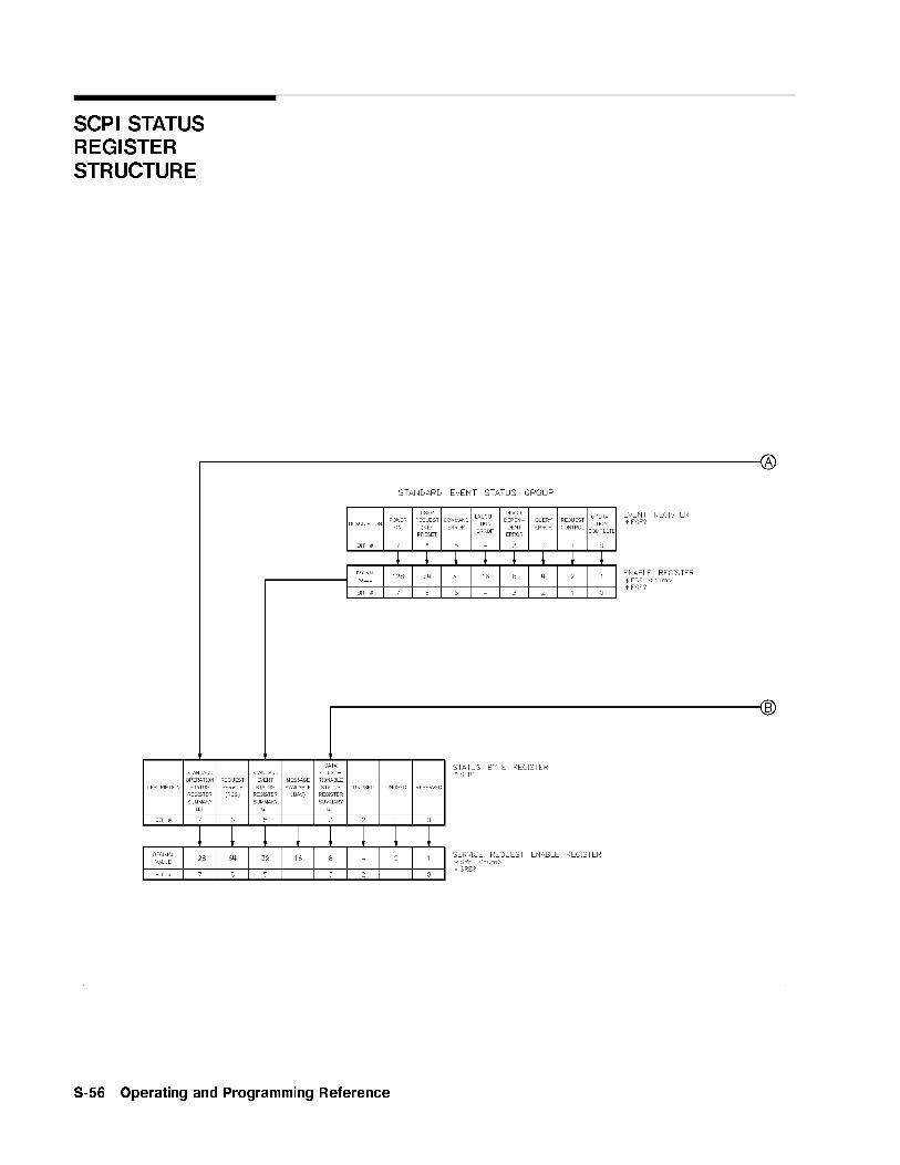
SCPI STATUSREGISTERSTRUCTURE
S-56 Operating and Programming Reference

SCPI STATUS REGISTER STRUCTURE
Operating and Programming Reference S-57
aaaaaaaaaaaaaaaaaaaaaaaaaaaaaaaaaaaaaaaaaaaaaaaaaaaaaaSecurity Menu
Function Group SYSTEM
Menu Map 8
Description This softkey accesses the security function softkeys.NNNNNNNNNNNNNNNNNNNNNNNNNNNNNNNNNNNNNNNNNBlank Display Turns o� the swept signal generator's data display,
active entry, and message line areas.NNNNNNNNNNNNNNNNNNNNNNNNNNNNNNNNNNNNNNClear Memory Writes alternating ones and zeros over all swept
signal generator state functions and save/recallregisters a selectable number of times, then returnsthe swept signal generator to the factory-presetstate of operation.NNNNNNNNNNNNNNNNNNNNNNNNNNNNN
Save Lock Disables the save function.NNNNNNNNNNNNNNNNNNNNNNNNNNNNNZero Freq Displays zeros for all accessible frequency
information.
The features listed above together with the softkeysNNNNNNNNNNNNNNNNNNNNNNNNNNNNNNNNNNNFreq Offset
andNNNNNNNNNNNNNNNNNNNNNNNNNNNNNFreq Mult provide the swept signal generator with security
controls for a variety of situations. The local lockout (LLO)programming command adds security when the swept signalgenerator is used in an ATE environment. A security calibrationconstant that can be accessed through the service adjustment menu(requires a password for access) is available also. Refer to the AgilentTechnologies 8360 B-Series Swept Signal Generator/8360 L-SeriesSwept CW Generator Service Guide for information on calibrationconstants.
See Also Softkeys listed above.\Using the Security Features" in Chapter 1
S-58 Operating and Programming Reference
NNNNNNNNNNNNNNNNNNNNNNNNNNSet Atten
aaaaaaaaaaaaaaaaaaaaaaaaaaaaaaaaaaaaaaaaaaaaaaaaaaaaaaaaaaaaaSelftest (Full)
Function Group SERVICE
Menu Map 6
Description This softkey activates the self-test function of the swept signalgenerator.
Programming Codes SCPI: *TST?Analyzer: NONE
See AlsoNNNNNNNNNNNNNNNNNNNNNNNNNNNNNNNNFault Menu , SCPI COMMAND SUMMARYChapter 4, \OPERATOR'S CHECK and ROUTINEMAINTENANCE"
aaaaaaaaaaaaaaaaaaaaaaaaaaaaaaaaaaaaaaSet Atten
Function Group POWER
Menu Map 5
Description This softkey lets you set the attenuator separately from the restof the ALC system. When an entry is made using this key, theattenuator is automatically uncoupled from the ALC system, sothat the �POWER LEVEL� key controls the ALC system apart from theattenuator.
Programming Codes SCPI: POWer:ATTenuation <num>[DB] orMAXimumjMINimumjUPjDOWNAnalyzer: SHLS <num>[DBjDM]
See Also �ALC�, �POWER LEVEL�,NNNNNNNNNNNNNNNNNNNNNNNNNNNNNNNNNNNNNNNNNUncoupl Atten
\Working with Mixers/Reverse Power E�ects" in Chapter 1
Operating and Programming Reference S-59
�SINGLE�
Function Group SWEEP
Menu Map 7
Description This hardkey selects single sweep mode, aborts any sweep in progressand initiates a single sweep at a rate determined by the sweep timefunction.
If you press �SINGLE� in the middle of a continuous sweep, the sweep isaborted and the swept signal generator retraces to the starting pointbut does not start a sweep. Press �SINGLE� a second time to start thesweep. The amber LED above the hardkey is lit when the function ison.
Programming Codes SCPI:
INITiate:CONTinuous OFFj0ABORtINITiate[:IMMediate]
Analyzer: S2
See Also �CONT�\Continuous, Single, and Manual Sweep Operation" in Chapter 1\Programming Typical Measurements" in Chapter 1
aaaaaaaaaaaaaaaaaaaaaaaaaaaaaaaaaaaaaaaaaaaaaaaaaaSoftware Rev
Function Group SYSTEM
Menu Map 8
Description This softkey displays the swept signal generator's programminglanguage, GPIB address, and �rmware date code.
Programming Codes SCPI: *IDN?Analyzer: OI
See AlsoNNNNNNNNNNNNNNNNNNNNNNNNNNNNNGPIB Menu , SCPI COMMAND SUMMARY
S-60 Operating and Programming Reference

�START�
�SPAN�
Function Group FREQUENCY
Menu Map 2
Description This hardkey lets you set a value for the frequency span in the centerfrequency/frequency span mode of swept frequency operation. Press�SPAN�, and use the entry area to enter the desired value. The sweptsignal generator sweeps from one half the span below to one halfabove the center frequency.
Certain center frequency and frequency span combinations cause theswept signal generator to limit the value entered. In general, anycombination that causes the swept signal generator to exceed itsminimum or maximum speci�ed frequency is limited.
Programming Codes SCPI:
FREQuency:SPAN <num>[freq su�x] orMAXimumjMINimumjUPjDOWNFREQuency:MODE SWEep
Analyzer: DF <num> [HzjKzjMzjGz]
See Also �CENTER�, �START�, �STOP�\Center Frequency/Span Operation" in Chapter 1
�START�
Function Group FREQUENCY
Menu Map 2
Description This hardkey activates swept frequency mode and makes the startfrequency parameter the active function. Press �START� and use theentry area to enter the desired value. The start/stop frequency mustbe separated by at least 2 Hz in order to remain in the frequencysweep mode. If start=stop frequency then the zero span mode isentered.
Operating and Programming Reference S-61

�START�
Programming Codes SCPI:
FREQuency:STARt <num>[freq su�x] orMAXimumjMINimumjUPjDOWNFREQuency:MODE SWEep
Analyzer: FA <num> [HzjKzjMzjGz]
See Also �CENTER�, �CW�, FREQUENCY �MENU�, �SPAN�, �STOP�\CW Operation and Start/Stop Frequency Sweep" in Chapter 1\Programming Typical Measurements" in Chapter 1
aaaaaaaaaaaaaaaaaaaaaaaaaaaaaaaaaaaaaaaaaaaaaaaaaaaaaaaaaaaaaaaaaStart=M1 Stop=M2
Function Group MARKER
Menu Map 3
Description This softkey changes the swept signal generator start frequencyto the frequency value of marker 1, and the stop frequency to thefrequency value of marker 2. The swept signal generator has beenreset to these start/stop values, unlike the softkey
NNNNNNNNNNNNNNNNNNNNNNNNNNNNNNNNNNNNNNM1--M2 Sweep
that changes the start/stop values only while active.
Programming Codes SCPI: SWEep[:FREQuency]:MARKer:XFERAnalyzer: SHMP
See AlsoNNNNNNNNNNNNNNNNNNNNNNNNNNNNNNNNNNNNNNM1--M2 Sweep
\Marker Operation" in Chapter 1
S-62 Operating and Programming Reference

NNNNNNNNNNNNNNNNNNNNNNNNNNNNNNNNNNNNNNNNNNNNNNNNNNNNNNNNNNNNNNNNNStart Sweep Trigger Bus
xFxFxFxFxFxFxFxFxFxFxFxFxFxFxFxFxFxFxFxFxFxFxFxFxFxFxFxFxFxFxFxFxFxFxFxFxFxFxFxFxFxFxFxFxFxFxFxFxFxFxFxFxFxF
Start Sweep
Trigger Auto
Function Group SWEEP
Menu Map 7
Description When this softkey is selected, the swept signal generatorautomatically triggers a sweep. This is the fastest way to accomplishthe sweep-retrace cycle. An asterisk next to the key label indicatesthat this feature is active.
Programming Codes SCPI: TRIGger:SOURce IMMediateAnalyzer: T1
See Also �CONT�, �SINGLE�,NNNNNNNNNNNNNNNNNNNNNNNNNNNNNNNNSweep Menu
xFxFxFxFxFxFxFxFxFxFxFxFxFxFxFxFxFxFxFxFxFxFxFxFxFxFxFxFxFxFxFxFxFxFxFxFxFxFxFxFxFxFxFxFxFxFxFxFxFxF
Start Sweep
Trigger Bus
Function Group SWEEP
Menu Map 7
Description When this softkey is selected, the swept signal generator waits for anGPIB trigger to trigger a sweep. An asterisk next to the key labelindicates that this feature is active.
Programming Codes SCPI: TRIGger:SOURce BUSAnalyzer: TS
See Also �CONT�, �SINGLE�,NNNNNNNNNNNNNNNNNNNNNNNNNNNNNNNNSweep Menu
Operating and Programming Reference S-63
xFxFxFxFxFxFxFxFxFxFxFxFxFxFxFxFxFxFxFxFxFxFxFxFxFxFxFxFxFxFxFxFxFxFxFxFxFxFxFxFxFxFxFxFxFxFxFxFxFxF
Start Sweep
Trigger Ext
Function Group SWEEP
Menu Map 7
Description When this softkey is selected, the swept signal generator waits for anexternal hardware trigger to trigger a sweep. Connect the triggerpulse to TRIGGER INPUT. It is activated on a TTL rising edge. Anasterisk next to the key label indicates that this feature is active.
Programming Codes SCPI: TRIGger:SOURce EXTAnalyzer: T3
See Also �CONT�, �SINGLE�,NNNNNNNNNNNNNNNNNNNNNNNNNNNNNNNNSweep Menu
xFxFxFxFxFxFxFxFxFxFxFxFxFxFxFxFxFxFxFxFxFxFxFxFxFxFxFxFxFxFxFxFxFxFxFxFxFxFxFxFxFxFxFxFxFxFxFxFxFxF
Step Control
Master
Function Group FREQUENCY
Menu Map 2
Description This softkey lets you designate the swept signal generator as themaster control in a dual swept signal generator measurement system.A dual swept signal generator system (two-tone measurementsystem) facilitates accurate device characterizations by providingone timebase reference for both sources. This technique reducesinstabilities from temperature or line voltage uctuations, or drift.
The swept signal generators can be operated in either rampsweep or step sweep modes for both �xed o�set and swept o�setmeasurements. Figure S-1 shows the connections required for atwo-tone system.
S-64 Operating and Programming Reference
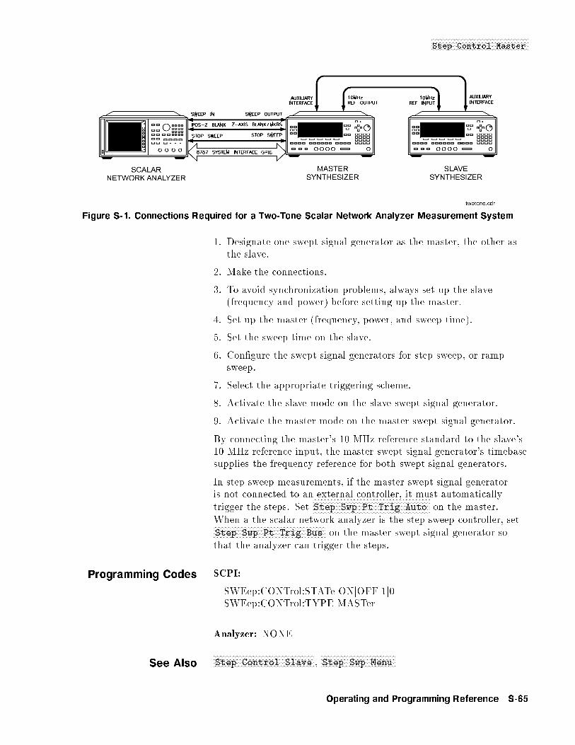
NNNNNNNNNNNNNNNNNNNNNNNNNNNNNNNNNNNNNNNNNNNNNNNNNNNNNNStep Control Master
Figure S-1. Connections Required for a Two-Tone Scalar Network Analyzer Measurement System
1. Designate one swept signal generator as the master, the other asthe slave.
2. Make the connections.
3. To avoid synchronization problems, always set up the slave(frequency and power) before setting up the master.
4. Set up the master (frequency, power, and sweep time).
5. Set the sweep time on the slave.
6. Con�gure the swept signal generators for step sweep, or rampsweep.
7. Select the appropriate triggering scheme.
8. Activate the slave mode on the slave swept signal generator.
9. Activate the master mode on the master swept signal generator.
By connecting the master's 10 MHz reference standard to the slave's10 MHz reference input, the master swept signal generator's timebasesupplies the frequency reference for both swept signal generators.
In step sweep measurements, if the master swept signal generatoris not connected to an external controller, it must automaticallytrigger the steps. Set
NNNNNNNNNNNNNNNNNNNNNNNNNNNNNNNNNNNNNNNNNNNNNNNNNNNNNNNNNNNNNNNNNStep Swp Pt Trig Auto on the master.
When a the scalar network analyzer is the step sweep controller, setNNNNNNNNNNNNNNNNNNNNNNNNNNNNNNNNNNNNNNNNNNNNNNNNNNNNNNNNNNNNNNStep Swp Pt Trig Bus on the master swept signal generator sothat the analyzer can trigger the steps.
Programming Codes SCPI:
SWEep:CONTrol:STATe ONjOFFj1j0SWEep:CONTrol:TYPE MASTer
Analyzer: NONE
See AlsoNNNNNNNNNNNNNNNNNNNNNNNNNNNNNNNNNNNNNNNNNNNNNNNNNNNNNNNNStep Control Slave ,
NNNNNNNNNNNNNNNNNNNNNNNNNNNNNNNNNNNNNNNNNStep Swp Menu
Operating and Programming Reference S-65

aaaaaaaaaaaaaaaaaaaaaaaaaaaaaaaaaaaaaaaaaaaaaaaaaaaaaaaaaaaaaaaaaaaaaaaaaStep Control Slave
Function Group FREQUENCY
Menu Map 2
Description This softkey lets you designate the swept signal generator as the slavein a dual swept signal generator measurement system. A dual sweptsignal generator system (two-tone measurement system) facilitatesaccurate device characterizations by providing one timebase referencefor both sources.
Figure S-1 shows the connections required for a two-tone system. Onthe message line, the status message EXT REF appears indicating theswept signal generator has an external timebase reference. The startand stop frequencies of the slave can be o�set above or below thoseset on the master for �xed o�set two-tone measurements.
To synchronize properly for swept o�set measurements, the0 to 10 volt sweep ramp must be actively sweeping on the slave. If aCW frequency is selected as the �xed LO frequency, the sweep rampis deactivated and the proper synchronization does not occur. Selecta center frequency with zero span to keep the slave's voltage sweepramp active and ensure proper synchronization.
For synthesized step sweep measurements, set the number ofsweep points on the slave the same as on the master swept signalgenerator. If the master swept signal generator is connected to anetwork analyzer, the analyzer automatically sets the master sweptsignal generator's step size to match the number of points displayedon the analyzer. Since the slave swept signal generator is notconnected to the analyzer, set the slave to match the master sweptsignal generator. Allow the master to trigger the slave's steps. SetNNNNNNNNNNNNNNNNNNNNNNNNNNNNNNNNNNNNNNNNNNNNNNNNNNNNNNNNNNNNNNStep Swp Pt Trig Ext on the slave swept signal generator.
For ramp sweep measurements, on the slave set the sweep timeequivalent to the master swept signal generator. If the master isconnected to a network analyzer, the slave's sweep time is slightlylonger than the master's because the analyzer does not stop thesweep precisely on the last point and if the sweep times are set tothe same value, the system may lock up. Use the following formulato determine the slave's sweep time for a system controlled by ananalyzer.
SweepTimeMaster � 1.03 = SweepTimeSlave
Setting the slave's sweep time 1.03 times greater, the master's sweeptime results in the slave sweep being 97% of the set value. When areduced sweep is not acceptable, sweep times can be set to the samevalue. Lock ups can be cleared by reentering the slave's sweep time.For �xed-o�set ramp sweep measurements, the same sweep time must
S-66 Operating and Programming Reference
NNNNNNNNNNNNNNNNNNNNNNNNNNNNNStep Dwell
be set on both the master and the slave. Since the master's sweeptime is typically determined by the measurement con�guration, setthe slave to match the master.
For more accurate ramp sweeps, selectNNNNNNNNNNNNNNNNNNNNNNNNNNNNNNNNNNNNNNNNNNNNNNNNNNNNNNNNNNNSwp Span Cal Always on
both the master and slave swept signal generators. When this featureis active it calibrates the frequency at the end of every frequencyband.
Programming Codes SCPI:
SWEep:CONTrol:STATe ONjOFFj1j0SWEep:CONTrol:TYPE SLAVe
Analyzer: NONE
See AlsoNNNNNNNNNNNNNNNNNNNNNNNNNNNNNNNNNNNNNNNNNNNNNNNNNNNNNNNNNNNStep Control Master ,
NNNNNNNNNNNNNNNNNNNNNNNNNNNNNNNNNNNNNNNNNStep Swp Menu
aaaaaaaaaaaaaaaaaaaaaaaaaaaaaaaaaaaaaaaaaaStep Dwell
Function Group FREQUENCY
Menu Map 2
Description This softkey lets you set dwell times for points in the steppedfrequency mode of sweep operation. The dwell time for points in stepfrequency sweep may range from 100 �s to 3.2 s. The actual timebetween points is the sum of dwell and phase lock times.
SelectNNNNNNNNNNNNNNNNNNNNNNNNNNNNNNNNStep Dwell , then use the entry area to enter the desired
value.
Programming Codes SCPI: SWEep[:FREQuency]:DWELl <num>[time su�x] orMAXimumjMINimumAnalyzer: NONE
See AlsoNNNNNNNNNNNNNNNNNNNNNNNNNNNNNNNNNNNNNNNNNStep Swp Menu ,
NNNNNNNNNNNNNNNNNNNNNNNNNNNNNNNNNNNNNNNNNNNNNNNSweep Mode Step
Operating and Programming Reference S-67

aaaaaaaaaaaaaaaaaaaaaaaaaaaaaaaaaaaaaaaaaaaaaaStep Points
Function Group FREQUENCY
Menu Map 2
Description This softkey lets you de�ne the number of step points in a steppedfrequency sweep. The number of points in a stepped sweep canrange from 2 to 801.
NNNNNNNNNNNNNNNNNNNNNNNNNNNNNStep Size and
NNNNNNNNNNNNNNNNNNNNNNNNNNNNNNNNNNNStep Points are dependent
variables. If you know how many steps are desired in a given sweep,use the softkey
NNNNNNNNNNNNNNNNNNNNNNNNNNNNNNNNNNNStep Points to set the desired value The step size
will be calculated automatically.
Programming Codes SCPI: SWEep[:FREQuency]:POINts <num>jMAXimumjMINimumAnalyzer: NONE
See AlsoNNNNNNNNNNNNNNNNNNNNNNNNNNNNNStep Size ,
NNNNNNNNNNNNNNNNNNNNNNNNNNNNNNNNNNNNNNNNNStep Swp Menu ,
NNNNNNNNNNNNNNNNNNNNNNNNNNNNNNNNNNNNNNNNNNNNNNNSweep Mode Step
\Using Step Sweep" in Chapter 1
aaaaaaaaaaaaaaaaaaaaaaaaaaaaaaaaaaaaaaStep Size
Function Group FREQUENCY
Menu Map 2
Description This softkey lets you specify the step size in a stepped frequencysweep. The range of increment size is dependent on frequencyspan and the number of step points desired, as given by theformula: STEP SIZE = SPAN � STEP POINTS.
NNNNNNNNNNNNNNNNNNNNNNNNNNNNNStep Size andNNNNNNNNNNNNNNNNNNNNNNNNNNNNNNNNNNN
Step Points are dependent variables, as shown by the formula. If
a particular step size is desired, use theNNNNNNNNNNNNNNNNNNNNNNNNNNNNNStep Size softkey to set
the desired increment. The number of step points is then calculatedautomatically.
Programming Codes SCPI: SWEep[:FREQuency]:STEP <num>[freq su�x] orMAXimumjMINimumAnalyzer: NONE
See AlsoNNNNNNNNNNNNNNNNNNNNNNNNNNNNNNNNNNNStep Points ,
NNNNNNNNNNNNNNNNNNNNNNNNNNNNNNNNNNNNNNNNNStep Swp Menu ,
NNNNNNNNNNNNNNNNNNNNNNNNNNNNNNNNNNNNNNNNNNNNNNNSweep Mode Step
\Using Step Sweep" in Chapter 1
S-68 Operating and Programming Reference
NNNNNNNNNNNNNNNNNNNNNNNNNNNNNNNNNNNNNStep Swp Menu
aaaaaaaaaaaaaaaaaaaaaaaaaaaaaaaaaaaaaaaaaaaaaaaaaaaaaaStep Swp Menu
Function Group FREQUENCY
Menu Map 2
Description This softkey reveals the stepped frequency sweep entry menu.NNNNNNNNNNNNNNNNNNNNNNNNNNNNNNNNNNNNNNNNNDwell Coupled Couples the dwell time for stepped
sweep points to ramp sweep, sweeptime.NNNNNNNNNNNNNNNNNNNNNNNNNNNNNNNNNNNNNNNNNNNNNNNNNNNNNNNNNNN
Step Control Master Causes the swept signal generatorto act as the master control ina dual swept signal generatormeasurement setup.NNNNNNNNNNNNNNNNNNNNNNNNNNNNNNNNNNNNNNNNNNNNNNNNNNNNNNNN
Step Control Slave Causes the swept signal generatorto act as the slave in a dual sweptsignal generator measurementsetup.NNNNNNNNNNNNNNNNNNNNNNNNNNNNNNNN
Step Dwell Sets the dwell time for points instepped sweep.NNNNNNNNNNNNNNNNNNNNNNNNNNNNNNNNNNN
Step Points Sets the number of points in astepped sweep.NNNNNNNNNNNNNNNNNNNNNNNNNNNNN
Step Size Sets the increment value for thepoints in a stepped sweep.NNNNNNNNNNNNNNNNNNNNNNNNNNNNNNNNNNNNNNNNNNNNNNNNNNNNNNNNNNNNNNNNN
Step Swp Pt Trig Auto Automatically steps the sweptsignal generator to the next point ina stepped sweep.NNNNNNNNNNNNNNNNNNNNNNNNNNNNNNNNNNNNNNNNNNNNNNNNNNNNNNNNNNNNNN
Step Swp Pt Trig Bus Steps the swept signal generator tothe next point in a stepped sweepwhen an GPIB trigger is received.NNNNNNNNNNNNNNNNNNNNNNNNNNNNNNNNNNNNNNNNNNNNNNNNNNNNNNNNNNNNNN
Step Swp Pt Trig Ext Steps the swept signal generator tothe next point in a stepped sweepwhen an external hardware triggeris received.
Programming Codes SCPI: NONEAnalyzer: NONE
See Also �START�, �STOP�,NNNNNNNNNNNNNNNNNNNNNNNNNNNNNNNNNNNNNNNNNNNNNNNSweep Mode Step , �SWEEP TIME�
\Using Step Sweep" in Chapter 1
Operating and Programming Reference S-69

xFxFxFxFxFxFxFxFxFxFxFxFxFxFxFxFxFxFxFxFxFxFxFxFxFxFxFxFxFxFxFxFxFxFxFxFxFxFxFxFxFxFxFxFxFxF
Step Swp Pt
Trig Auto
Function Group FREQUENCY
Menu Map 2
Description When this softkey is selected, the swept signal generatorautomatically steps to the next point in the stepped frequency sweepuntil all points are swept. The time between points is equal to thesum of the dwell and phase lock times. An asterisk next to the keylabel indicates that this feature is active.
Programming Codes SCPI: SWEep:TRIGger:SOURce IMMediateAnalyzer: NONE
See AlsoNNNNNNNNNNNNNNNNNNNNNNNNNNNNNNNNNNNNNNNNNStep Swp Menu ,
NNNNNNNNNNNNNNNNNNNNNNNNNNNNNNNNNNNNNNNNNNNNNNNSweep Mode Step
\Using Step Sweep" in Chapter 1
xFxFxFxFxFxFxFxFxFxFxFxFxFxFxFxFxFxFxFxFxFxFxFxFxFxFxFxFxFxFxFxFxFxFxFxFxFxFxFxFxFxFxFxFxFxF
Step Swp Pt
Trig Bus
Function Group FREQUENCY
Menu Map 2
Description When this softkey is selected, the swept signal generator steps to thenext point in a stepped frequency sweep when an GPIB trigger(*TRG, <GET>) is received (leading edge TTL). When the lastfrequency point is reached and continuous sweep is selected, thenext trigger causes the step sweep to return to the start frequency.Connect the trigger signal to the TRIGGER INPUT BNC. Anasterisk next to the key label indicates this feature is active.
Programming Codes SCPI: SWEep:TRIGger:SOURce BUSAnalyzer: TS
See AlsoNNNNNNNNNNNNNNNNNNNNNNNNNNNNNNNNNNNNNNNNNStep Swp Menu ,
NNNNNNNNNNNNNNNNNNNNNNNNNNNNNNNNNNNNNNNNNNNNNNNSweep Mode Step
S-70 Operating and Programming Reference

�STOP�
xFxFxFxFxFxFxFxFxFxFxFxFxFxFxFxFxFxFxFxFxFxFxFxFxFxFxFxFxFxFxFxFxFxFxFxFxFxFxFxFxFxFxFxFxFxF
Step Swp Pt
Trig Ext
Function Group FREQUENCY
Menu Map 2
Description When this softkey is selected, the swept signal generator steps to thenext point in the
stepped frequency sweep when an external hardware trigger isreceived. When the last frequency point is reached and continuoussweep is selected, the next trigger causes the step sweep to return tothe start frequency. Connect the trigger signal to the TRIGGERINPUT BNC. An asterisk next to the key label indicates that thisfeature is active.
Programming Codes SCPI: SWEep:TRIGger:SOURce EXTAnalyzer: TS
See AlsoNNNNNNNNNNNNNNNNNNNNNNNNNNNNNNNNNNNNNNNNNStep Swp Menu ,
NNNNNNNNNNNNNNNNNNNNNNNNNNNNNNNNNNNNNNNNNNNNNNNSweep Mode Step
\Using Step Sweep" in Chapter 1
�STOP�
Function Group FREQUENCY
Menu Map NONE
Description This hardkey activates swept frequency mode and makes the stopfrequency parameter the active function. The start/stop frequencymust be separated by at least 2 Hz in order to remain in thefrequency sweep mode. If start=stop frequency then the zero spanmode is entered.
Programming Codes SCPI:
FREQuency:STOP <num>[freq su�x] orMAXimumjMINimumjUPjDOWNFREQuency:MODE:SWEep
Analyzer: FB <num> [HzjKzjMzjGz]
Operating and Programming Reference S-71
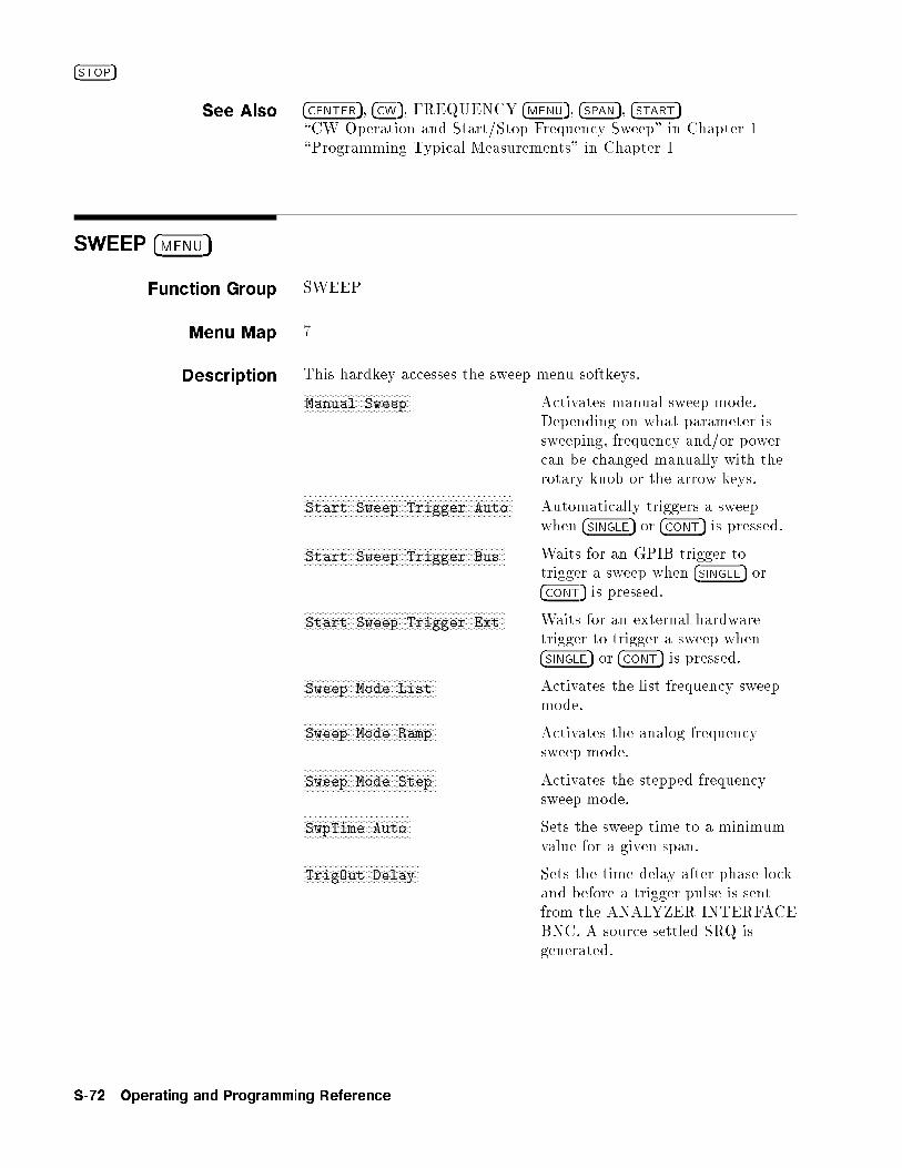
�STOP�
See Also �CENTER�, �CW�, FREQUENCY �MENU�, �SPAN�, �START�\CW Operation and Start/Stop Frequency Sweep" in Chapter 1\Programming Typical Measurements" in Chapter 1
SWEEP �MENU�
Function Group SWEEP
Menu Map 7
Description This hardkey accesses the sweep menu softkeys.NNNNNNNNNNNNNNNNNNNNNNNNNNNNNNNNNNNNNNManual Sweep Activates manual sweep mode.
Depending on what parameter issweeping, frequency and/or powercan be changed manually with therotary knob or the arrow keys.NNNNNNNNNNNNNNNNNNNNNNNNNNNNNNNNNNNNNNNNNNNNNNNNNNNNNNNNNNNNNNNNNNNNNNNNNN
Start Sweep Trigger Auto Automatically triggers a sweepwhen �SINGLE� or �CONT� is pressed.
NNNNNNNNNNNNNNNNNNNNNNNNNNNNNNNNNNNNNNNNNNNNNNNNNNNNNNNNNNNNNNNNNNNNNNNStart Sweep Trigger Bus Waits for an GPIB trigger to
trigger a sweep when �SINGLE� or�CONT� is pressed.
NNNNNNNNNNNNNNNNNNNNNNNNNNNNNNNNNNNNNNNNNNNNNNNNNNNNNNNNNNNNNNNNNNNNNNNStart Sweep Trigger Ext Waits for an external hardware
trigger to trigger a sweep when�SINGLE� or �CONT� is pressed.
NNNNNNNNNNNNNNNNNNNNNNNNNNNNNNNNNNNNNNNNNNNNNNNSweep Mode List Activates the list frequency sweep
mode.NNNNNNNNNNNNNNNNNNNNNNNNNNNNNNNNNNNNNNNNNNNNNNNSweep Mode Ramp Activates the analog frequency
sweep mode.NNNNNNNNNNNNNNNNNNNNNNNNNNNNNNNNNNNNNNNNNNNNNNNSweep Mode Step Activates the stepped frequency
sweep mode.NNNNNNNNNNNNNNNNNNNNNNNNNNNNNNNNNNNNNNSwpTime Auto Sets the sweep time to a minimum
value for a given span.NNNNNNNNNNNNNNNNNNNNNNNNNNNNNNNNNNNNNNNNNTrigOut Delay Sets the time delay after phase-lock
and before a trigger pulse is sentfrom the ANALYZER INTERFACEBNC. A source settled SRQ isgenerated.
S-72 Operating and Programming Reference
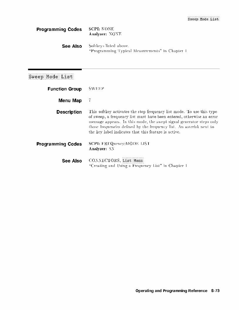
NNNNNNNNNNNNNNNNNNNNNNNNNNNNNNNNNNNNNNNNNNNSweep Mode List
Programming Codes SCPI: NONEAnalyzer: NONE
See Also Softkeys listed above.\Programming Typical Measurements" in Chapter 1
aaaaaaaaaaaaaaaaaaaaaaaaaaaaaaaaaaaaaaaaaaaaaaaaaaaaaaaaaaaaaSweep Mode List
Function Group SWEEP
Menu Map 7
Description This softkey activates the step frequency list mode. To use this typeof sweep, a frequency list must have been entered, otherwise an errormessage appears. In this mode, the swept signal generator steps onlythose frequencies de�ned by the frequency list. An asterisk next tothe key label indicates that this feature is active.
Programming Codes SCPI: FREQuency:MODE LISTAnalyzer: SN
See Also CONNECTORS,NNNNNNNNNNNNNNNNNNNNNNNNNNNNNList Menu
\Creating and Using a Frequency List" in Chapter 1
Operating and Programming Reference S-73
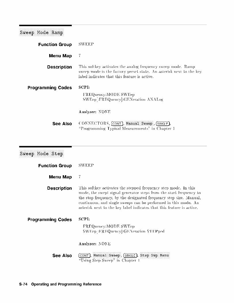
aaaaaaaaaaaaaaaaaaaaaaaaaaaaaaaaaaaaaaaaaaaaaaaaaaaaaaaaaaaaaSweep Mode Ramp
Function Group SWEEP
Menu Map 7
Description This softkey activates the analog frequency sweep mode. Rampsweep mode is the factory preset state. An asterisk next to the keylabel indicates that this feature is active.
Programming Codes SCPI:
FREQuency:MODE SWEepSWEep[:FREQuency]:GENeration ANALog
Analyzer: NONE
See Also CONNECTORS, �CONT�,NNNNNNNNNNNNNNNNNNNNNNNNNNNNNNNNNNNNNNManual Sweep , �SINGLE�,
\Programming Typical Measurements" in Chapter 1
aaaaaaaaaaaaaaaaaaaaaaaaaaaaaaaaaaaaaaaaaaaaaaaaaaaaaaaaaaaaaSweep Mode Step
Function Group SWEEP
Menu Map 7
Description This softkey activates the stepped frequency step mode. In thismode, the swept signal generator steps from the start frequency tothe stop frequency, by the designated frequency step size. Manual,continuous, and single sweeps can be performed in this mode. Anasterisk next to the key label indicates that this feature is active.
Programming Codes SCPI:
FREQuency:MODE SWEepSWEep[:FREQuency]:GENeration STEPped
Analyzer: NONE
See Also �CONT�,NNNNNNNNNNNNNNNNNNNNNNNNNNNNNNNNNNNNNNManual Sweep , �SINGLE�,
NNNNNNNNNNNNNNNNNNNNNNNNNNNNNNNNNNNNNNNNNStep Swp Menu
\Using Step Sweep" in Chapter 1
S-74 Operating and Programming Reference

NNNNNNNNNNNNNNNNNNNNNNNNNNNNNNNNNNNNNNNNNNNNNNSwp Span CalOnce
xFxFxFxFxFxFxFxFxFxFxFxFxFxFxFxFxFxFxFxFxFxFxFxFxFxFxFxFxFxFxFxFxFxFxFxFxFxFxFxFxFxFxFxFxFxFxFxFxFxF
Swp Span Cal
Always
Function Group USER CAL
Menu Map 9
Description This softkey causes a sweep span calibration each time the frequencyspan is changed. An asterisk next to the key label indicates thisfeature is active.
Programming Codes SCPI: CALibration:SPAN:AUTO ONjOFFj1j0Analyzer: NONE
See AlsoNNNNNNNNNNNNNNNNNNNNNNNNNNNNNNNNNNNNNNNNNFreq Cal Menu
\Using Frequency Calibration,"
xFxFxFxFxFxFxFxFxFxFxFxFxFxFxFxFxFxFxFxFxFxFxFxFxFxFxFxFxFxFxFxFxFxFxFxFxFxFxFxFxFxFxFxFxFxFxFxFxFxF
Swp Span Cal
Once
Function Group USER CAL
Menu Map 9
Description This softkey activates sweep span calibration immediately andperforms it only once. An asterisk next to the key label indicates thisfeature is active.
Programming Codes SCPI: CALibration:SPAN[:EXECute]Analyzer: NONE
See AlsoNNNNNNNNNNNNNNNNNNNNNNNNNNNNNNNNNNNNNNNNNFreq Cal Menu
\Using Frequency Calibration,"
Operating and Programming Reference S-75
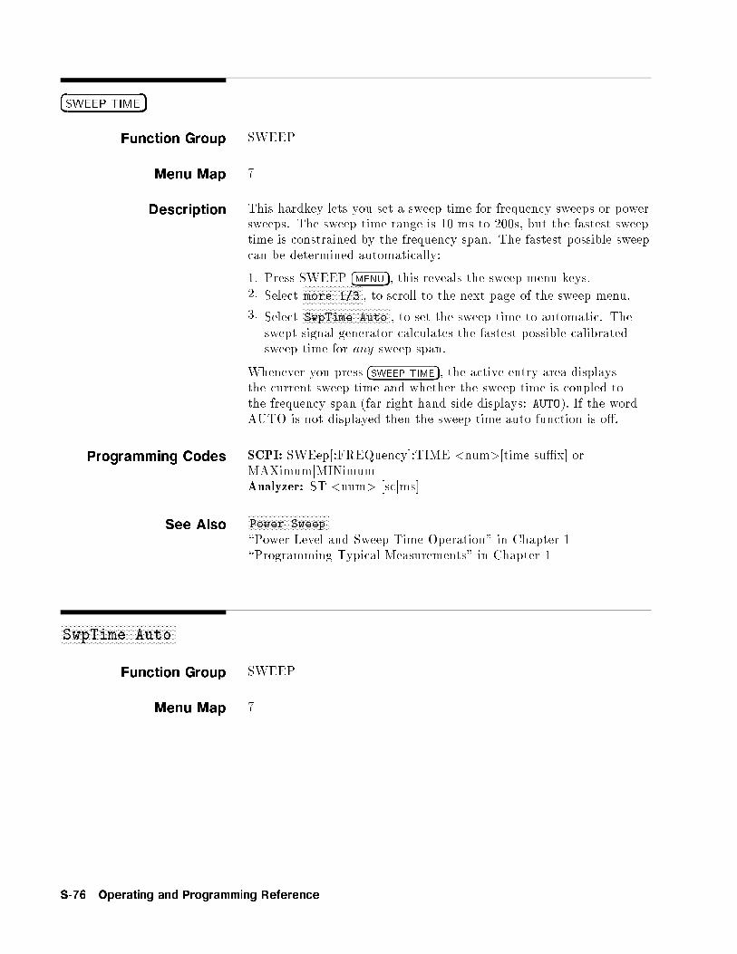
�SWEEP TIME�
Function Group SWEEP
Menu Map 7
Description This hardkey lets you set a sweep time for frequency sweeps or powersweeps. The sweep time range is 10 ms to 200s, but the fastest sweeptime is constrained by the frequency span. The fastest possible sweepcan be determined automatically:
1. Press SWEEP �MENU�, this reveals the sweep menu keys.2. Select
NNNNNNNNNNNNNNNNNNNNNNNNNNmore 1/3 , to scroll to the next page of the sweep menu.
3. SelectNNNNNNNNNNNNNNNNNNNNNNNNNNNNNNNNNNNNNNSwpTime Auto , to set the sweep time to automatic. The
swept signal generator calculates the fastest possible calibratedsweep time for any sweep span.
Whenever you press �SWEEP TIME�, the active entry area displaysthe current sweep time and whether the sweep time is coupled tothe frequency span (far right hand side displays: AUTO). If the wordAUTO is not displayed then the sweep time auto function is o�.
Programming Codes SCPI: SWEep[:FREQuency]:TIME <num>[time su�x] orMAXimumjMINimumAnalyzer: ST <num> [scjms]
See AlsoNNNNNNNNNNNNNNNNNNNNNNNNNNNNNNNNNNNPower Sweep
\Power Level and Sweep Time Operation" in Chapter 1\Programming Typical Measurements" in Chapter 1
aaaaaaaaaaaaaaaaaaaaaaaaaaaaaaaaaaaaaaaaaaaaaaaaaaSwpTime Auto
Function Group SWEEP
Menu Map 7
S-76 Operating and Programming Reference
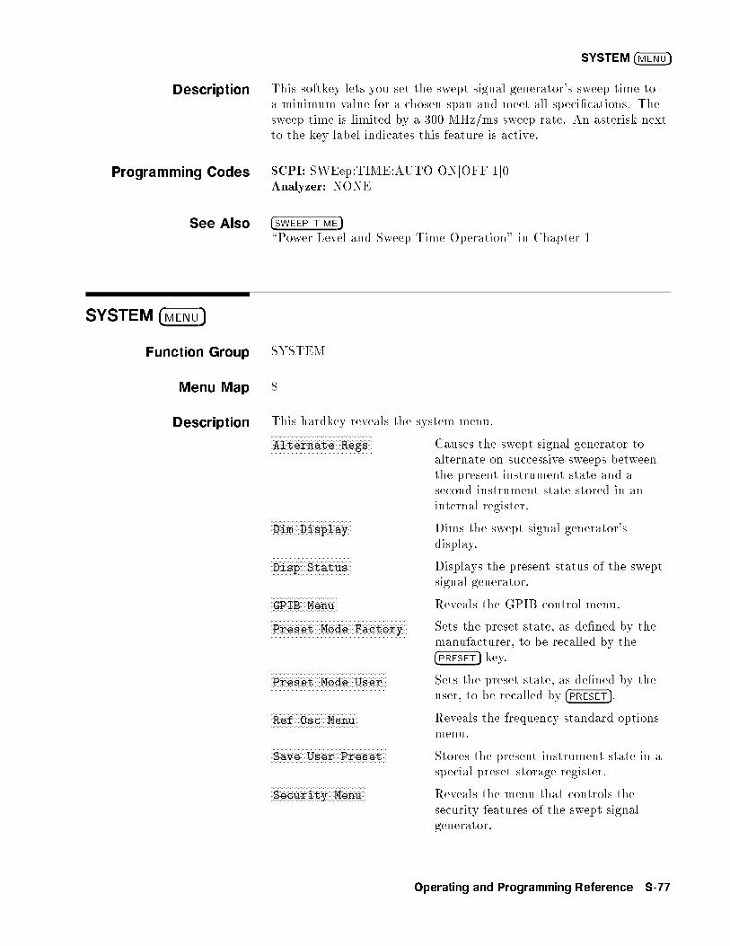
SYSTEM �MENU�
Description This softkey lets you set the swept signal generator's sweep time toa minimum value for a chosen span and meet all speci�cations. Thesweep time is limited by a 300 MHz/ms sweep rate. An asterisk nextto the key label indicates this feature is active.
Programming Codes SCPI: SWEep:TIME:AUTO ONjOFFj1j0Analyzer: NONE
See Also �SWEEP TIME�\Power Level and Sweep Time Operation" in Chapter 1
SYSTEM �MENU�
Function Group SYSTEM
Menu Map 8
Description This hardkey reveals the system menu.NNNNNNNNNNNNNNNNNNNNNNNNNNNNNNNNNNNNNNNNNNNNAlternate Regs Causes the swept signal generator to
alternate on successive sweeps betweenthe present instrument state and asecond instrument state stored in aninternal register.NNNNNNNNNNNNNNNNNNNNNNNNNNNNNNNNNNN
Dim Display Dims the swept signal generator'sdisplay.NNNNNNNNNNNNNNNNNNNNNNNNNNNNNNNNNNN
Disp Status Displays the present status of the sweptsignal generator.NNNNNNNNNNNNNNNNNNNNNNNNNNNNN
GPIB Menu Reveals the GPIB control menu.NNNNNNNNNNNNNNNNNNNNNNNNNNNNNNNNNNNNNNNNNNNNNNNNNNNNNNNNNNNPreset Mode Factory Sets the preset state, as de�ned by the
manufacturer, to be recalled by the�PRESET� key.
NNNNNNNNNNNNNNNNNNNNNNNNNNNNNNNNNNNNNNNNNNNNNNNNNNPreset Mode User Sets the preset state, as de�ned by the
user, to be recalled by �PRESET�.NNNNNNNNNNNNNNNNNNNNNNNNNNNNNNNNNNNNNNRef Osc Menu Reveals the frequency standard options
menu.NNNNNNNNNNNNNNNNNNNNNNNNNNNNNNNNNNNNNNNNNNNNNNNNNNSave User Preset Stores the present instrument state in a
special preset storage register.NNNNNNNNNNNNNNNNNNNNNNNNNNNNNNNNNNNNNNNNNSecurity Menu Reveals the menu that controls the
security features of the swept signalgenerator.
Operating and Programming Reference S-77
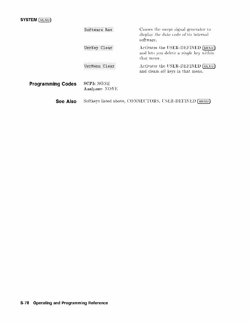
SYSTEM �MENU�
NNNNNNNNNNNNNNNNNNNNNNNNNNNNNNNNNNNNNNSoftware Rev Causes the swept signal generator to
display the date code of its internalsoftware.NNNNNNNNNNNNNNNNNNNNNNNNNNNNNNNNNNNNNN
UsrKey Clear Activates the USER-DEFINED �MENU�and lets you delete a single key withinthat menu.NNNNNNNNNNNNNNNNNNNNNNNNNNNNNNNNNNNNNNNNN
UsrMenu Clear Activates the USER-DEFINED �MENU�and clears all keys in that menu.
Programming Codes SCPI: NONEAnalyzer: NONE
See Also Softkeys listed above, CONNECTORS, USER-DEFINED �MENU�
S-78 Operating and Programming Reference
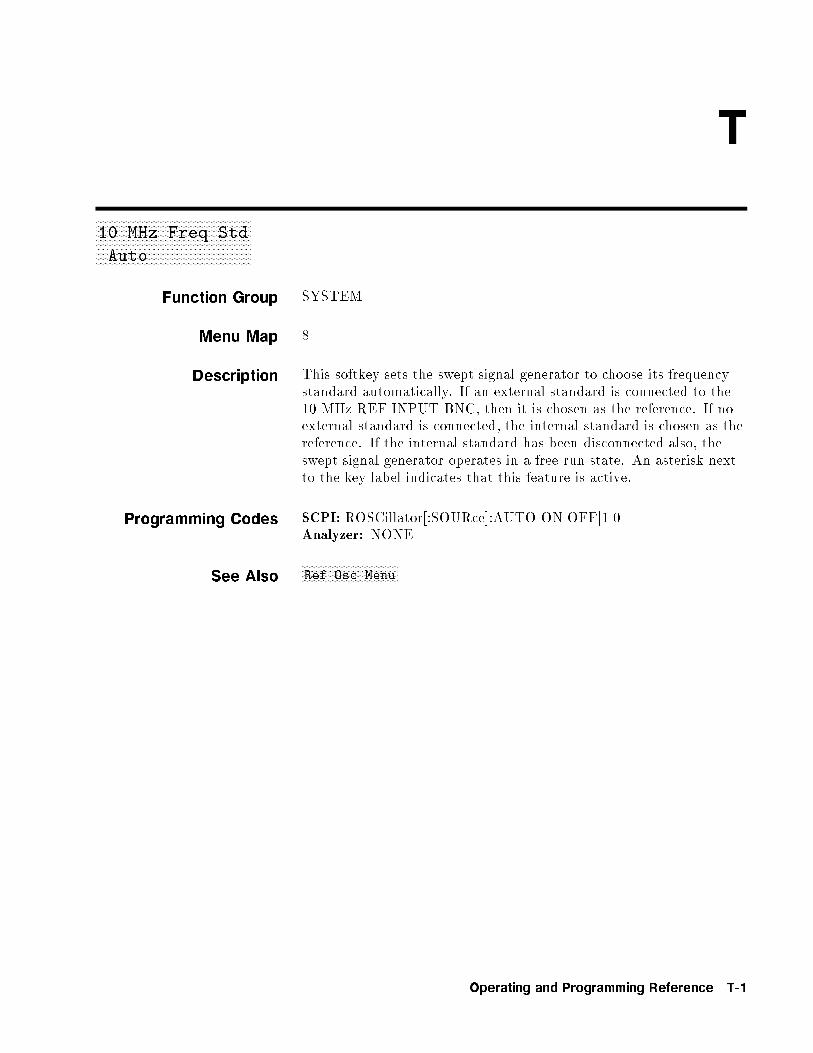
T
xFxFxFxFxFxFxFxFxFxFxFxFxFxFxFxFxFxFxFxFxFxFxFxFxFxFxFxFxFxFxFxFxFxFxFxFxFxFxFxFxFxFxFxFxFxFxFxFxFxFxFxFxFxFxFxFxFxFxFxFxF
10 MHz Freq Std
Auto
Function Group SYSTEM
Menu Map 8
Description This softkey sets the swept signal generator to choose its frequencystandard automatically. If an external standard is connected to the10 MHz REF INPUT BNC, then it is chosen as the reference. If noexternal standard is connected, the internal standard is chosen as thereference. If the internal standard has been disconnected also, theswept signal generator operates in a free run state. An asterisk nextto the key label indicates that this feature is active.
Programming Codes SCPI: ROSCillator[:SOURce]:AUTO ONjOFFj1j0Analyzer: NONE
See AlsoNNNNNNNNNNNNNNNNNNNNNNNNNNNNNNNNNNNNNNRef Osc Menu
Operating and Programming Reference T-1
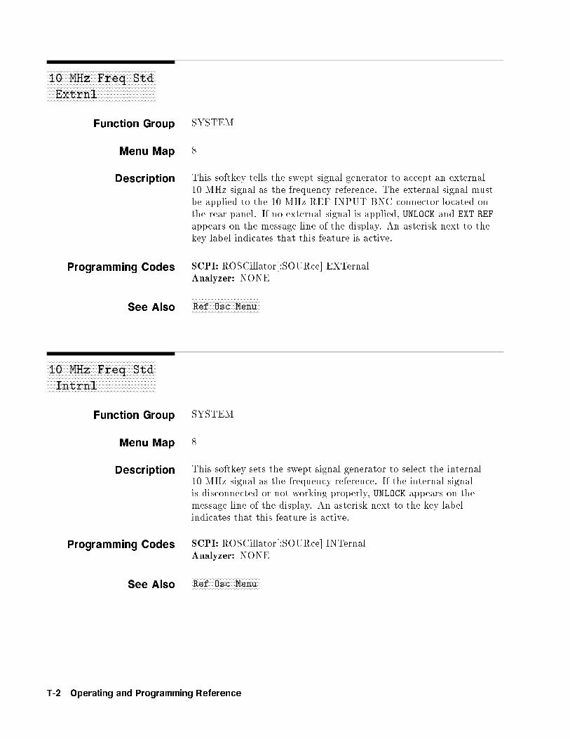
xFxFxFxFxFxFxFxFxFxFxFxFxFxFxFxFxFxFxFxFxFxFxFxFxFxFxFxFxFxFxFxFxFxFxFxFxFxFxFxFxFxFxFxFxFxFxFxFxFxFxFxFxFxFxFxFxFxFxFxFxF
10 MHz Freq Std
Extrnl
Function Group SYSTEM
Menu Map 8
Description This softkey tells the swept signal generator to accept an external10 MHz signal as the frequency reference. The external signal mustbe applied to the 10 MHz REF INPUT BNC connector located onthe rear panel. If no external signal is applied, UNLOCK and EXT REF
appears on the message line of the display. An asterisk next to thekey label indicates that this feature is active.
Programming Codes SCPI: ROSCillator[:SOURce] EXTernalAnalyzer: NONE
See AlsoNNNNNNNNNNNNNNNNNNNNNNNNNNNNNNNNNNNNNNRef Osc Menu
xFxFxFxFxFxFxFxFxFxFxFxFxFxFxFxFxFxFxFxFxFxFxFxFxFxFxFxFxFxFxFxFxFxFxFxFxFxFxFxFxFxFxFxFxFxFxFxFxFxFxFxFxFxFxFxFxFxFxFxFxF
10 MHz Freq Std
Intrnl
Function Group SYSTEM
Menu Map 8
Description This softkey sets the swept signal generator to select the internal10 MHz signal as the frequency reference. If the internal signalis disconnected or not working properly, UNLOCK appears on themessage line of the display. An asterisk next to the key labelindicates that this feature is active.
Programming Codes SCPI: ROSCillator[:SOURce] INTernalAnalyzer: NONE
See AlsoNNNNNNNNNNNNNNNNNNNNNNNNNNNNNNNNNNNNNNRef Osc Menu
T-2 Operating and Programming Reference

NNNNNNNNNNNNNNNNNNNNNNNNNNNNNNNNNNNNNTracking Menu
xFxFxFxFxFxFxFxFxFxFxFxFxFxFxFxFxFxFxFxFxFxFxFxFxFxFxFxFxFxFxFxFxFxFxFxFxFxFxFxFxFxFxFxFxFxFxFxFxFxFxFxFxFxFxFxFxFxFxFxFxF
10 MHz Freq Std
None
Function Group SYSTEM
Menu Map 8
Description This softkey sets the reference oscillator to a free-run state, whereno frequency reference is used. An asterisk next to the key labelindicates that this feature is active.
Programming Codes SCPI: ROSCillator[:SOURce] NONEAnalyzer: NONE
See AlsoNNNNNNNNNNNNNNNNNNNNNNNNNNNNNNNNNNNNNNRef Osc Menu
aaaaaaaaaaaaaaaaaaaaaaaaaaaaaaaaaaaaaaaaaaaaaaaaaaaaaaTracking Menu
Function Group POWER, USER CAL
Menu Map 5, 9
Description In the menu structure there are two occurrences of this softkey. Oneoccurs in the POWER �MENU�, the other occurs in the USER CAL�MENU�. Both softkeys operate the same way. These softkeys accessthe tracking menu.NNNNNNNNNNNNNNNNNNNNNNNNNNNNNNNNAuto Track Realigns the swept signal generator's output
�lter and oscillator to maximize output powerfor the swept frequency mode.NNNNNNNNNNNNNNNNNNNNNNNNNNNNNNNNNNNNNNNNNNNN
Peak RF Always Periodically realigns the swept signalgenerator's output �lter and oscillator tomaximize output power for the CW frequencymode.NNNNNNNNNNNNNNNNNNNNNNNNNNNNNNNNNNNNNN
Peak RF Once Realigns the swept signal generator's output�lter and oscillator to maximize output powerfor the CW frequency mode.
Operating and Programming Reference T-3

NNNNNNNNNNNNNNNNNNNNNNNNNNNNNNNNNNNNNTracking Menu
Programming Codes SCPI: NONEAnalyzer: NONE
See Also Softkeys listed above.\Using the Tracking Feature" in Chapter 1
aaaaaaaaaaaaaaaaaaaaaaaaaaaaaaaaaaaaaaaaaaaaaaaaaaaaaaTrigOut Delay
Function Group SWEEP
Menu Map 7
Description This softkey lets you specify the amount of time after phase-lockbefore a trigger pulse is sent out of the TRIGGER OUTPUT BNC.The delay can be set from 0 to 3.2 seconds. An asterisk next to thekey label indicates this feature is active.
Programming Codes SCPI: TRIGger:ODELay <num>[time su�x]Analyzer: NONE
See AlsoNNNNNNNNNNNNNNNNNNNNNNNNNNNNNNNNNNNNNNNNNNNNNNNNNNNNNNNNNNNNNNNNNNNNNNNNNNStart Sweep Trigger Auto ,
NNNNNNNNNNNNNNNNNNNNNNNNNNNNNNNNNNNNNNNNNNNNNNNNNNNNNNNNNNNNNNNNNNNNNNNStart Sweep Trigger Bus ,NNNNNNNNNNNNNNNNNNNNNNNNNNNNNNNNNNNNNNNNNNNNNNNNNNNNNNNNNNNNNNNNNNNNNNN
Start Sweep Trigger Ext
T-4 Operating and Programming Reference
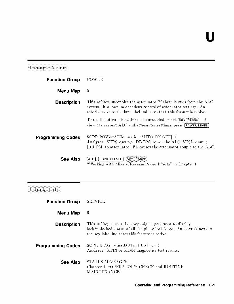
U
aaaaaaaaaaaaaaaaaaaaaaaaaaaaaaaaaaaaaaaaaaaaaaaaaaaaaaUncoupl Atten
Function Group POWER
Menu Map 5
Description This softkey uncouples the attenuator (if there is one) from the ALCsystem. It allows independent control of attenuator settings. Anasterisk next to the key label indicates that this feature is active.
To set the attenuator after it is uncoupled, selectNNNNNNNNNNNNNNNNNNNNNNNNNNNNNSet Atten . To
view the current ALC and attenuator settings, press �POWER LEVEL�.
Programming Codes SCPI: POWer:ATTentuation:AUTO ONjOFFj1j0Analyzer: SHPS <num> [DBjDM] to set the ALC, SHSL <num>[DBjDM] to attenuator. PL causes the attenuator couple to the ALC.
See Also �ALC�, �POWER LEVEL�,NNNNNNNNNNNNNNNNNNNNNNNNNNNNNSet Atten
\Working with Mixers/Reverse Power E�ects" in Chapter 1
aaaaaaaaaaaaaaaaaaaaaaaaaaaaaaaaaaaaaaaaaaaaaaUnlock Info
Function Group SERVICE
Menu Map 6
Description This softkey causes the swept signal generator to displaylock/unlocked status of all the phase-lock-loops. An asterisk next tothe key label indicates this feature is active.
Programming Codes SCPI: DIAGnostics:OUTput:UNLocks?Analyzer: SHT3 or SHM4 diagnostics test results.
See Also STATUS MESSAGESChapter 4, \OPERATOR'S CHECK and ROUTINEMAINTENANCE"
Operating and Programming Reference U-1

aaaaaaaaaaaaaaaaaaaaaaaaaaaaaaaaaaaaaaaaaaaaaaaaaaaaaaUp/Down Power
Function Group POWER
Menu Map 5
Description This softkey activates the power step size function. It can be setfrom 0.01 to 20 dB. In this mode, power is stepped by the up/downarrow keys. An asterisk next to the key label indicates this feature isactive.
Programming Codes SCPI:
POWer:STEP[:INCrement] <num>[DB] orMAXimumjMINimumPOWer:STEP:AUTO ONjOFFj1j0
Analyzer: SP or SHPL and UP or DOWN
See AlsoNNNNNNNNNNNNNNNNNNNNNNNNNNNNNNNNNNNNNNNNNUp/Dn Size CW ,
NNNNNNNNNNNNNNNNNNNNNNNNNNNNNNNNNNNNNNNNNNNNNNNNNNUp/Dn Size Swept
\Programming Typical Measurements" in Chapter 1
aaaaaaaaaaaaaaaaaaaaaaaaaaaaaaaaaaaaaaaaaaaaaaaaaaaaaaUp/Dn Size CW
Function Group FREQUENCY
Menu Map 2
Description This softkey lets you set the frequency step size for the CWfrequency mode. The step size may be set from 1 Hz to10 GHz. The factory preset size is 100 MHz. CW frequency isincremented/decremented by pressing the up/down arrow keys.
If an underline cursor appears under a digit in the entry display, thenthe value will be modi�ed by the up/down arrow keys or the rotaryknob. The increment/decrement size in this case is the underlineddigit by the power of 10.
If the up/down function is on (asterisk next to key label) and thecursor is not under one of the active entry area digits, then frequencyvalue is changed by the up/down size using either the up/down arrowkeys or the rotary knob.
U-2 Operating and Programming Reference

NNNNNNNNNNNNNNNNNNNNNNNNNNNNNNNNNNNNNNNNNNNNNNUp/Dn Size Swept
Programming Codes SCPI: FREQuency:STEP[:INCR] <num>[freq su�x] orMAXimumjMINimumAnalyzer: SF or SHCF <num> [HzjKzjMzjGz]
See AlsoNNNNNNNNNNNNNNNNNNNNNNNNNNNNNNNNNNNNNNManual Sweep ,
NNNNNNNNNNNNNNNNNNNNNNNNNNNNNNNNNNNNNNNNNNNNNNNSweep Mode Step ,
NNNNNNNNNNNNNNNNNNNNNNNNNNNNNNNNNNNNNNNNNNNNNNNNNNUp/Dn Size Swept
aaaaaaaaaaaaaaaaaaaaaaaaaaaaaaaaaaaaaaaaaaaaaaaaaaaaaaaaaaaaaaaaaUp/Dn Size Swept
Function Group FREQUENCY
Menu Map 2
Description This softkey sets the frequency step size in the swept frequency stepmode. The step size may be set from 1 Hz to 10 GHz. The factorypreset step size is 100 MHz. Step size values are entered using theentry area.
If an underline cursor appears under a digit in the entry display, thenthe value will be modi�ed by the up/down arrow keys or the rotaryknob. The increment/decrement size in this case is the underlineddigit by the power of 10.
If the up/down function is on (asterisk next to key label) and thecursor is not under one of the active entry area digits, then frequencyvalue is changed by the up/down size using either the up/down arrowkeys or the rotary knob.
Programming Codes SCPI: FREQuency:STEP[:INCR] <num>[freq su�x] orMAXimumjMINimumAnalyzer: SF or SHCF <num> [HzjKzjMzjGz]
See AlsoNNNNNNNNNNNNNNNNNNNNNNNNNNNNNNNNNNNNNNNNNUp/Dn Size CW
Operating and Programming Reference U-3

�USER CAL�
Function Group USER CAL
Menu Map 9
Description This hardkey accesses the user calibration softkeys.NNNNNNNNNNNNNNNNNNNNNNNNNNNNNNNNNNNFullUsr Cal Performs a complete alignment as
determined by the instrument settings.NNNNNNNNNNNNNNNNNNNNNNNNNNNNNNNNNNNNNNNNNTracking Menu Accesses the softkeys of the tracking
menu.NNNNNNNNNNNNNNNNNNNNNNNNNNNNNNNNNNNAM Cal Menu Accesses the AM calibration menu.NNNNNNNNNNNNNNNNNNNNNNNNNNNNNNNNNNNNNNNNNFreq Cal Menu Accesses the Frequency span calibration
menu.NNNNNNNNNNNNNNNNNNNNNNNNNNNNNNNNNNNExt Det Cal Uses an external power meter to
calibrate an external detector's outputvoltage relative to power.
Programming Codes NONE
See Also Softkeys listed above.\Optimizing Swept Signal Generator Performance" in Chapter 1
U-4 Operating and Programming Reference

USER DEFINED �MENU�
USER DEFINED�MENU�
Function Group USER DEFINED
Menu Map NONE
Description This hardkey reveals the customized menu created by selectingsoftkeys and assigning them to this menu. The user de�ned menu isempty until you assign keys to it. Three sections (12 key assignmentlocations) of menu are available for key assignment.
Any softkey can be assigned to any of the 12 positions. A softkeyassigned to the user de�ned menu performs as if it is in its homemenu. Pressing the �PRESET� key does not erase the contents of thismenu.
Programming Codes SCPI: NONEAnalyzer: NONE
See Also �ASSIGN�, �PRIOR�,NNNNNNNNNNNNNNNNNNNNNNNNNNNNNNNNNNNNNNUsrKey Clear ,
NNNNNNNNNNNNNNNNNNNNNNNNNNNNNNNNNNNNNNNNNUsrMenu Clear
Operating and Programming Reference U-5

aaaaaaaaaaaaaaaaaaaaaaaaaaaaaaaaaaaaaaaaaaaaaaaaaaUsrKey Clear
Function Group SYSTEM
Menu Map 8
Description This softkey lets you recall the user de�ned menu and remove asingle softkey that appears in that menu.
1. SelectNNNNNNNNNNNNNNNNNNNNNNNNNNNNNNNNNNNNNNUsrKey Clear . The user de�ned menu appears in the
softkey label area. The active entry area displays:
->Press USER Soft Key to Clear
2. Select the softkey you wish to remove from the menu. The activeentry area turns o� and the softkey is removed from the userde�ned menu. The user de�ned menu remains in the softkey labelarea.
Programming Codes SCPI: NONEAnalyzer: NONE
See Also �ASSIGN�, USER DEFINED �MENU�,NNNNNNNNNNNNNNNNNNNNNNNNNNNNNNNNNNNNNNNNNUsrMenu Clear
aaaaaaaaaaaaaaaaaaaaaaaaaaaaaaaaaaaaaaaaaaaaaaaaaaaaaaUsrMenu Clear
Function Group SYSTEM
Menu Map 8
Description This softkey recalls the user de�ned menu and removes all softkeysassigned to that menu. The empty user de�ned menu remains in thesoftkey label area.
Programming Codes SCPI: NONEAnalyzer: NONE
See Also �ASSIGN�, USER DEFINED �MENU�,NNNNNNNNNNNNNNNNNNNNNNNNNNNNNNNNNNNNNNUsrKey Clear
U-6 Operating and Programming Reference
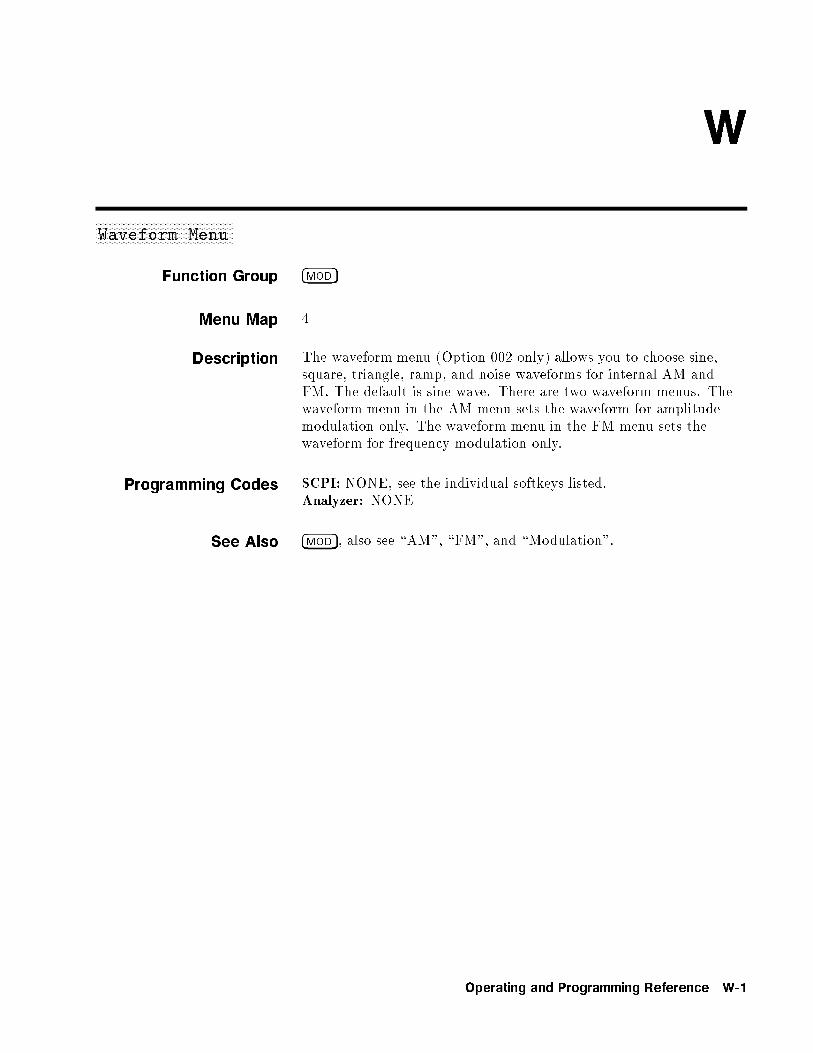
W
aaaaaaaaaaaaaaaaaaaaaaaaaaaaaaaaaaaaaaaaaaaaaaaaaaaaaaWaveform Menu
Function Group �MOD�
Menu Map 4
Description The waveform menu (Option 002 only) allows you to choose sine,square, triangle, ramp, and noise waveforms for internal AM andFM. The default is sine wave. There are two waveform menus. Thewaveform menu in the AM menu sets the waveform for amplitudemodulation only. The waveform menu in the FM menu sets thewaveform for frequency modulation only.
Programming Codes SCPI: NONE, see the individual softkeys listed.Analyzer: NONE
See Also �MOD�, also see \AM", \FM", and \Modulation".
Operating and Programming Reference W-1

Z
aaaaaaaaaaaaaaaaaaaaaaaaaaaaaaaaaaaaaaZero Freq
Function Group SYSTEM
Menu Map 8
Description This softkey lets you enable a security feature that displays zeroes forall accessible frequency information. Once this security feature isactivated, it can be turned o� by a front panel �PRESET�. An asterisknext to the key label indicates that this feature is active.
Programming Codes SCPI: SYSTem:SECurity[:STATe] ONAnalyzer: NONE
See AlsoNNNNNNNNNNNNNNNNNNNNNNNNNNNNNNNNNNNNNNNNNSecurity Menu
aaaaaaaaaaaaaaaaaaZoom
Function Group FREQUENCY
Menu Map 2
Description This softkey activates the CF/Span sweep mode (zoom). In thismode, span is controlled by the up/down arrow keys. Centerfrequency is controlled by the rotary knob or the numeric entry keys.The left and right arrows control the resolution with which the centerfrequency can be changed. This is a front-panel-only feature and isinaccessible over GPIB.
Programming Codes SCPI: NONEAnalyzer: NONE
See Also �CENTER�, �SPAN�
Operating and Programming Reference Z-1
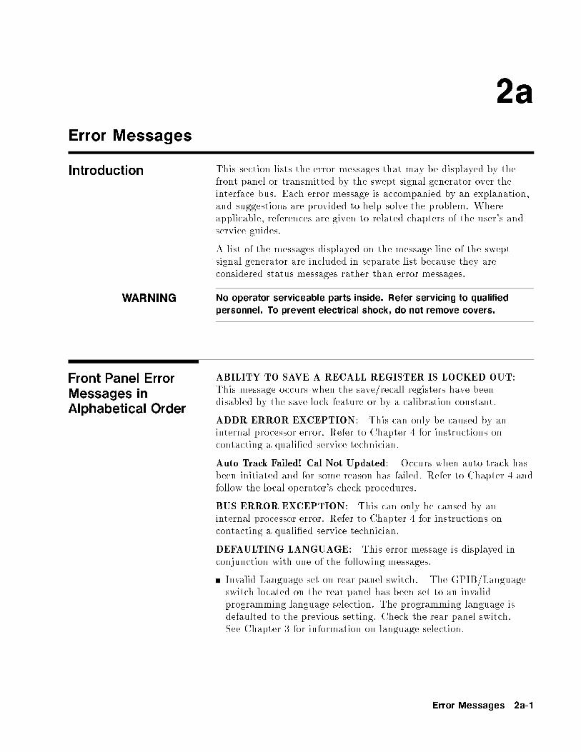
2a
Error Messages
Introduction This section lists the error messages that may be displayed by thefront panel or transmitted by the swept signal generator over theinterface bus. Each error message is accompanied by an explanation,and suggestions are provided to help solve the problem. Whereapplicable, references are given to related chapters of the user's andservice guides.
A list of the messages displayed on the message line of the sweptsignal generator are included in separate list because they areconsidered status messages rather than error messages.
WARNING No operator serviceable parts inside. Refer servicing to qualified
personnel. To prevent electrical shock, do not remove covers.
Front Panel ErrorMessages inAlphabetical Order
ABILITY TO SAVE A RECALL REGISTER IS LOCKED OUT:This message occurs when the save/recall registers have beendisabled by the save lock feature or by a calibration constant.
ADDR ERROR EXCEPTION: This can only be caused by aninternal processor error. Refer to Chapter 4 for instructions oncontacting a quali�ed service technician.
Auto Track Failed! Cal Not Updated: Occurs when auto track hasbeen initiated and for some reason has failed. Refer to Chapter 4 andfollow the local operator's check procedures.
BUS ERROR EXCEPTION: This can only be caused by aninternal processor error. Refer to Chapter 4 for instructions oncontacting a quali�ed service technician.
DEFAULTING LANGUAGE: This error message is displayed inconjunction with one of the following messages.
Invalid Language set on rear panel switch. The GPIB/Languageswitch located on the rear panel has been set to an invalidprogramming language selection. The programming language isdefaulted to the previous setting. Check the rear panel switch.See Chapter 3 for information on language selection.
Error Messages 2a-1
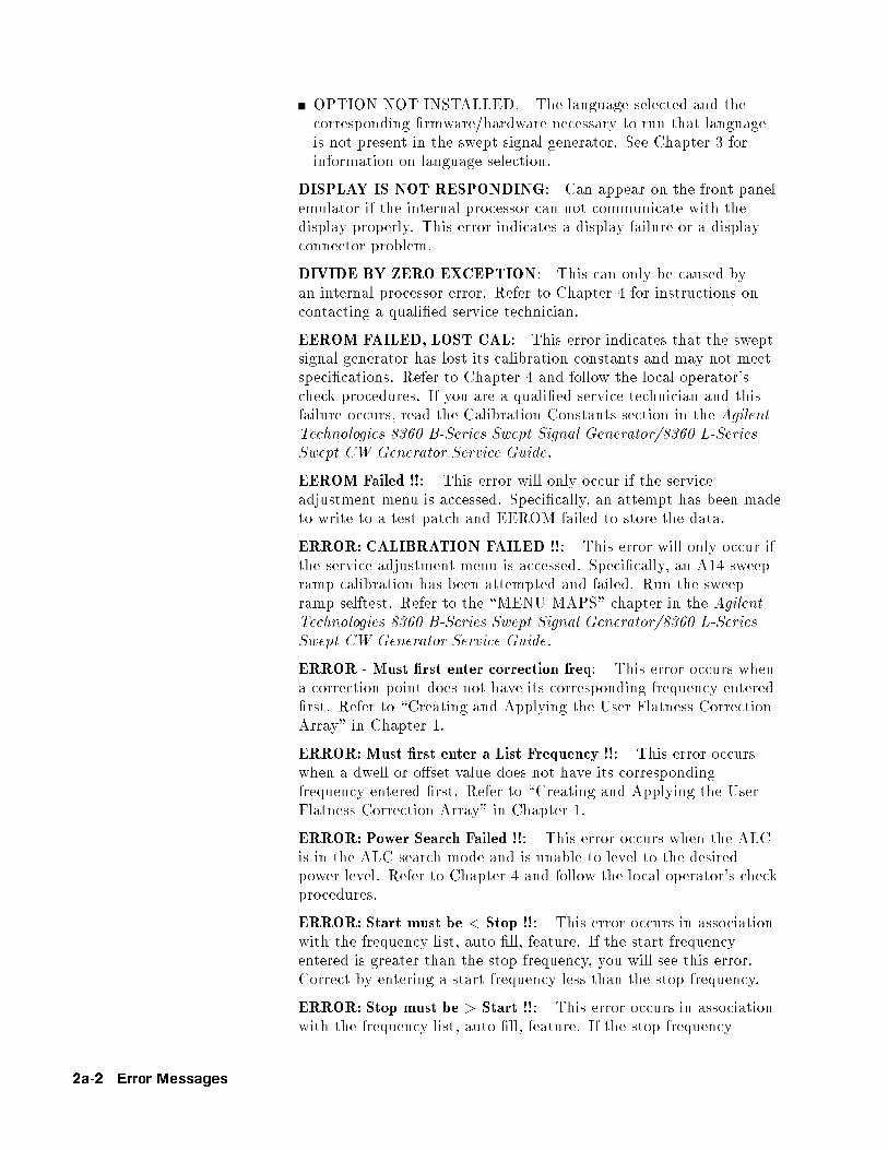
OPTION NOT INSTALLED. The language selected and thecorresponding �rmware/hardware necessary to run that languageis not present in the swept signal generator. See Chapter 3 forinformation on language selection.
DISPLAY IS NOT RESPONDING: Can appear on the front panelemulator if the internal processor can not communicate with thedisplay properly. This error indicates a display failure or a displayconnector problem.
DIVIDE BY ZERO EXCEPTION: This can only be caused byan internal processor error. Refer to Chapter 4 for instructions oncontacting a quali�ed service technician.
EEROM FAILED, LOST CAL: This error indicates that the sweptsignal generator has lost its calibration constants and may not meetspeci�cations. Refer to Chapter 4 and follow the local operator'scheck procedures. If you are a quali�ed service technician and thisfailure occurs, read the Calibration Constants section in the AgilentTechnologies 8360 B-Series Swept Signal Generator/8360 L-SeriesSwept CW Generator Service Guide.
EEROM Failed !!: This error will only occur if the serviceadjustment menu is accessed. Speci�cally, an attempt has been madeto write to a test patch and EEROM failed to store the data.
ERROR: CALIBRATION FAILED !!: This error will only occur ifthe service adjustment menu is accessed. Speci�cally, an A14 sweepramp calibration has been attempted and failed. Run the sweepramp selftest. Refer to the \MENU MAPS" chapter in the AgilentTechnologies 8360 B-Series Swept Signal Generator/8360 L-SeriesSwept CW Generator Service Guide.
ERROR - Must �rst enter correction freq: This error occurs whena correction point does not have its corresponding frequency entered�rst. Refer to \Creating and Applying the User Flatness CorrectionArray" in Chapter 1.
ERROR: Must �rst enter a List Frequency !!: This error occurswhen a dwell or o�set value does not have its correspondingfrequency entered �rst. Refer to \Creating and Applying the UserFlatness Correction Array" in Chapter 1.
ERROR: Power Search Failed !!: This error occurs when the ALCis in the ALC search mode and is unable to level to the desiredpower level. Refer to Chapter 4 and follow the local operator's checkprocedures.
ERROR: Start must be < Stop !!: This error occurs in associationwith the frequency list, auto �ll, feature. If the start frequencyentered is greater than the stop frequency, you will see this error.Correct by entering a start frequency less than the stop frequency.
ERROR: Stop must be > Start !!: This error occurs in associationwith the frequency list, auto �ll, feature. If the stop frequency
2a-2 Error Messages
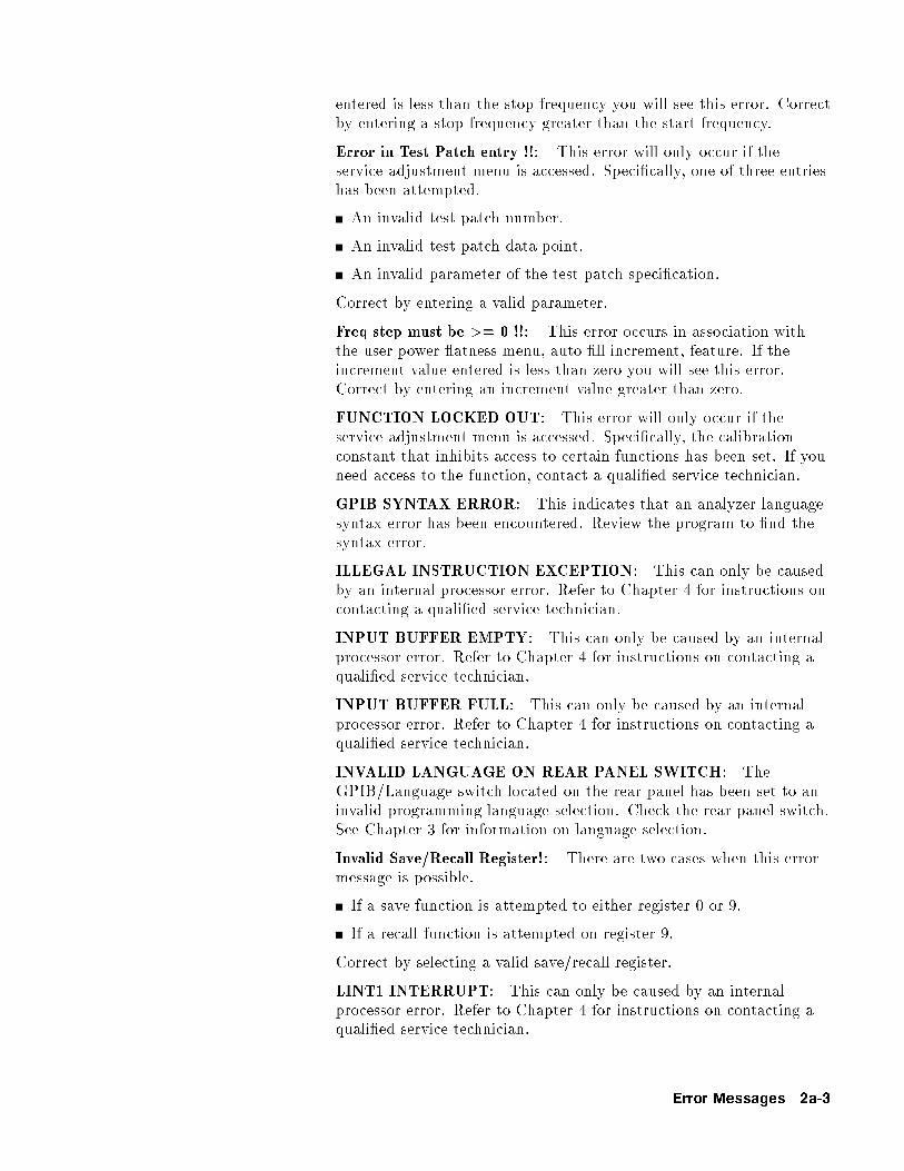
entered is less than the stop frequency you will see this error. Correctby entering a stop frequency greater than the start frequency.
Error in Test Patch entry !!: This error will only occur if theservice adjustment menu is accessed. Speci�cally, one of three entrieshas been attempted.
An invalid test patch number.
An invalid test patch data point.
An invalid parameter of the test patch speci�cation.
Correct by entering a valid parameter.
Freq step must be >= 0 !!: This error occurs in association withthe user power atness menu, auto �ll increment, feature. If theincrement value entered is less than zero you will see this error.Correct by entering an increment value greater than zero.
FUNCTION LOCKED OUT: This error will only occur if theservice adjustment menu is accessed. Speci�cally, the calibrationconstant that inhibits access to certain functions has been set. If youneed access to the function, contact a quali�ed service technician.
GPIB SYNTAX ERROR: This indicates that an analyzer languagesyntax error has been encountered. Review the program to �nd thesyntax error.
ILLEGAL INSTRUCTION EXCEPTION: This can only be causedby an internal processor error. Refer to Chapter 4 for instructions oncontacting a quali�ed service technician.
INPUT BUFFER EMPTY: This can only be caused by an internalprocessor error. Refer to Chapter 4 for instructions on contacting aquali�ed service technician.
INPUT BUFFER FULL: This can only be caused by an internalprocessor error. Refer to Chapter 4 for instructions on contacting aquali�ed service technician.
INVALID LANGUAGE ON REAR PANEL SWITCH: TheGPIB/Language switch located on the rear panel has been set to aninvalid programming language selection. Check the rear panel switch.See Chapter 3 for information on language selection.
Invalid Save/Recall Register!: There are two cases when this errormessage is possible.
If a save function is attempted to either register 0 or 9.
If a recall function is attempted on register 9.
Correct by selecting a valid save/recall register.
LINT1 INTERRUPT: This can only be caused by an internalprocessor error. Refer to Chapter 4 for instructions on contacting aquali�ed service technician.
Error Messages 2a-3

LINT2 INTERRUPT: This can only be caused by an internalprocessor error. Refer to Chapter 4 for instructions on contacting aquali�ed service technician.
LINT6 INTERRUPT: This can only be caused by an internalprocessor error. Refer to Chapter 4 for instructions on contacting aquali�ed service technician.
Number of pts must be >= 2 !!: This error occurs in associationwith the user power atness, auto �ll number of points, feature. Ifthe number of points requested is less than two, you will see thiserror message. Correct by entering number of points greater than orequal to two.
OPTION NOT INSTALLED: This error occurs when the GPIBlanguage switch is set to a con�guration requiring a certain�rmware/hardware combination to be present in the swept signalgenerator. See Chapter 3 for information on language selection andsee \Speci�cations" for information on option available.
PRIV VIOLATION EXCEPTION: This can only be caused byan internal processor error. Refer to Chapter 4 for instructions oncontacting a quali�ed service technician.
RECALL REGISTERS LOST: This message can appear inassociation with the security menu feature, memory clear. Also, aweak, dead, or disconnected internal battery can cause this message.Refer to Chapter 4 for instructions on contacting a quali�ed servicetechnician.
Selftest REQUIRES system interface OFF: This error messageindicates that the swept signal generator is connected to a networkanalyzer and can not run selftest. Correct by disconnecting thesystem interface cable from the swept signal generator.
SPURIOUS INTERRUPT: This can only be caused by an internalprocessor error. Refer to Chapter 4 for instructions on contacting aquali�ed service technician.
SYSTEM CONTROLLER ON BUS: This error message isgenerated when an external controller is active on the GPIB andthe swept signal generator has attempted to act as the controller.Disconnect the GPIB interface or return the swept signal generatorto LOCAL operation and repeat the request.
TOO MANY CORRECTION PTS REQUESTED: This erroroccurs in association with the user power atness menu. Themaximum number of correction points has been reached or theaddition of the points requested will exceed the maximum. Themaximum number of points available is 801.
TOO MANY LIST POINTS REQUESTED: This error occurs inassociation with the frequency list menu. The maximum number oflist points has been reached or the addition of the points requestedwill exceed the maximum. The maximum number of points availableis 801.
2a-4 Error Messages

TRACE EXCEPTION: This can only be caused by an internalprocessor error. Refer to Chapter 4 for instructions on contacting aquali�ed service technician.
TRAP0 EXCEPTION: This can only be caused by an internalprocessor error. Refer to Chapter 4 for instructions on contacting aquali�ed service technician.
TRAP3 EXCEPTION: This can only be caused by an internalprocessor error. Refer to Chapter 4 for instructions on contacting aquali�ed service technician.
Too many test patches !!: This error will only occur if the serviceadjustment menu is accessed. Speci�cally, the maximum number oftest patches has been reached and can accept no more.
WAIT|SAVING CALIBRATION: This error will only occur if theservice adjustment menu is accessed. Speci�cally, a save calibrationhas been initiated and not yet completed when another request ismade.
WRONG PASSWORD: This error occurs when the serviceadjustment menu password is entered incorrectly or the wrongpassword has been used. Quali�ed service technicians, refer to\ADJUSTMENTS," in the Agilent Technologies 8360 B-Series SweptSignal Generator/8360 L-Series Swept CW Generator Service Guidefor more information.
SCPI ErrorMessages inNumerical Order
Swept Signal GeneratorSpecific SCPI Error
Messages
0, No Error: This message indicates that the device has no errorsand is currently ready to perform the operations for which it isdesigned.
1, FUNCTION DISABLED: The particular function invoked hasbeen disabled by a calibration constant. If you need access to thefunction, contact a quali�ed service technician.
2, Wrong password: This error occurs when the service adjustmentmenu password is entered incorrectly or the wrong password has beenused. Quali�ed service technicians, refer to \ADJUSTMENTS," inthe Agilent Technologies 8360 B-Series Swept Signal Generator/8360 L-Series Swept CW Generator Service Guide for moreinformation.
4, Unable to store data in EEROM
5, Not allowed to change address
Error Messages 2a-5
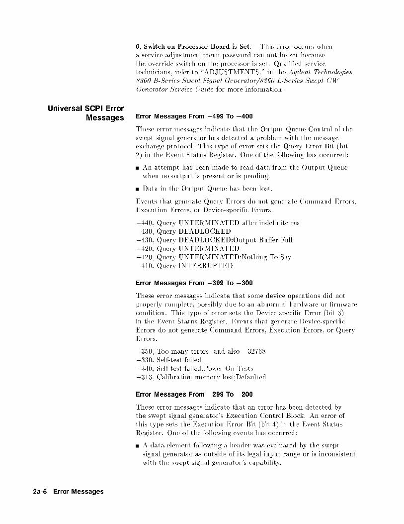
6, Switch on Processor Board is Set: This error occurs whena service adjustment menu password can not be set becausethe override switch on the processor is set. Quali�ed servicetechnicians, refer to \ADJUSTMENTS," in the Agilent Technologies8360 B-Series Swept Signal Generator/8360 L-Series Swept CWGenerator Service Guide for more information.
Universal SCPI ErrorMessages Error Messages From �499 To �400
These error messages indicate that the Output Queue Control of theswept signal generator has detected a problem with the messageexchange protocol. This type of error sets the Query Error Bit (bit2) in the Event Status Register. One of the following has occurred:
An attempt has been made to read data from the Output Queuewhen no output is present or is pending.
Data in the Output Queue has been lost.
Events that generate Query Errors do not generate Command Errors,Execution Errors, or Device-speci�c Errors.
�440, Query UNTERMINATED after inde�nite res�430, Query DEADLOCKED�430, Query DEADLOCKED;Output Bu�er Full�420, Query UNTERMINATED�420, Query UNTERMINATED;Nothing To Say�410, Query INTERRUPTED
Error Messages From �399 To �300
These error messages indicate that some device operations did notproperly complete, possibly due to an abnormal hardware or �rmwarecondition. This type of error sets the Device-speci�c Error (bit 3)in the Event Status Register. Events that generate Device-speci�cErrors do not generate Command Errors, Execution Errors, or QueryErrors.
�350, Too many errors and also �32768�330, Self-test failed�330, Self-test failed;Power-On Tests�313, Calibration memory lost;Defaulted
Error Messages From �299 To �200
These error messages indicate that an error has been detected bythe swept signal generator's Execution Control Block. An error ofthis type sets the Execution Error Bit (bit 4) in the Event StatusRegister. One of the following events has occurred:
A data element following a header was evaluated by the sweptsignal generator as outside of its legal input range or is inconsistentwith the swept signal generator's capability.
2a-6 Error Messages
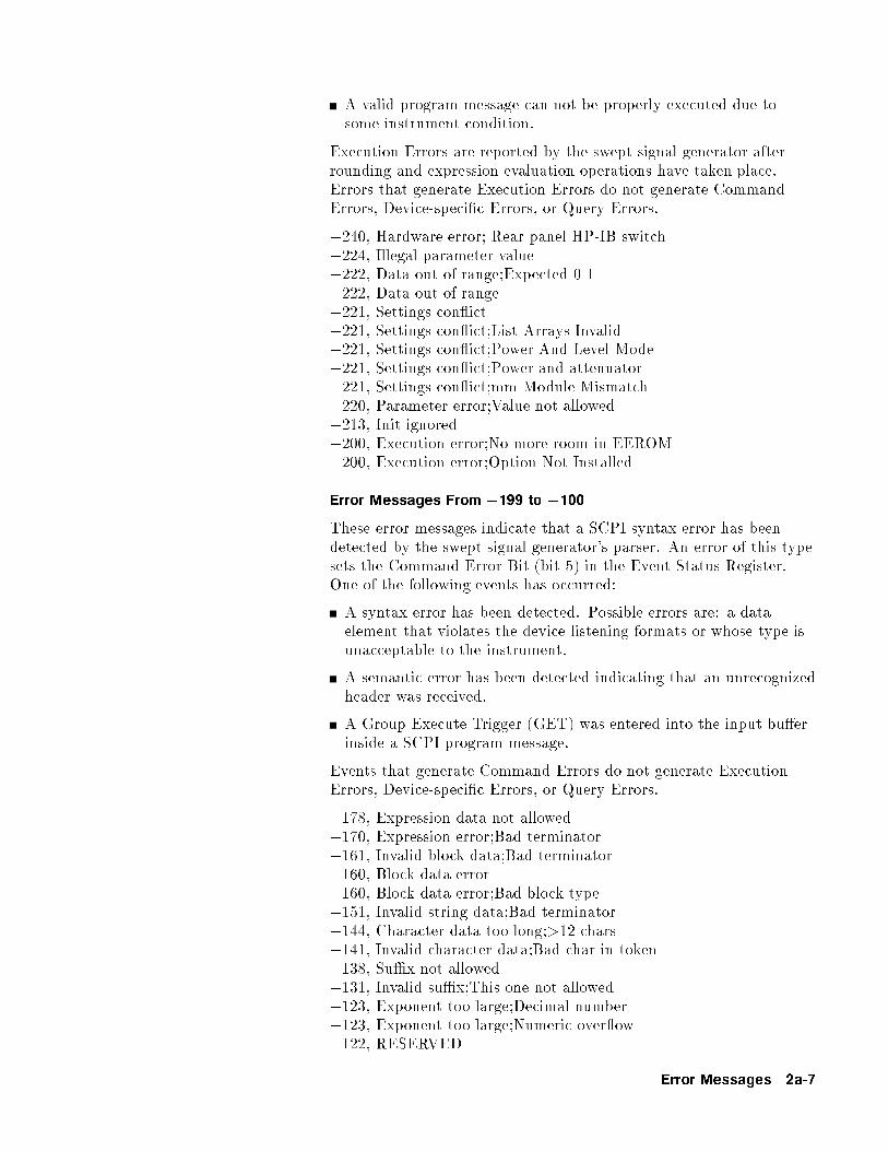
A valid program message can not be properly executed due tosome instrument condition.
Execution Errors are reported by the swept signal generator afterrounding and expression evaluation operations have taken place.Errors that generate Execution Errors do not generate CommandErrors, Device-speci�c Errors, or Query Errors.
�240, Hardware error; Rear panel HP-IB switch�224, Illegal parameter value�222, Data out of range;Expected 0-1�222, Data out of range�221, Settings con ict�221, Settings con ict;List Arrays Invalid�221, Settings con ict;Power And Level Mode�221, Settings con ict;Power and attenuator�221, Settings con ict;mm Module Mismatch�220, Parameter error;Value not allowed�213, Init ignored�200, Execution error;No more room in EEROM�200, Execution error;Option Not Installed
Error Messages From �199 to �100
These error messages indicate that a SCPI syntax error has beendetected by the swept signal generator's parser. An error of this typesets the Command Error Bit (bit 5) in the Event Status Register.One of the following events has occurred:
A syntax error has been detected. Possible errors are: a dataelement that violates the device listening formats or whose type isunacceptable to the instrument.
A semantic error has been detected indicating that an unrecognizedheader was received.
A Group Execute Trigger (GET) was entered into the input bu�erinside a SCPI program message.
Events that generate Command Errors do not generate ExecutionErrors, Device-speci�c Errors, or Query Errors.
�178, Expression data not allowed�170, Expression error;Bad terminator�161, Invalid block data;Bad terminator�160, Block data error�160, Block data error;Bad block type�151, Invalid string data;Bad terminator�144, Character data too long;>12 chars�141, Invalid character data;Bad char in token�138, Su�x not allowed�131, Invalid su�x;This one not allowed�123, Exponent too large;Decimal number�123, Exponent too large;Numeric over ow�122, RESERVED
Error Messages 2a-7

�121, Invalid character in number�120, Numeric data error;Bad format�120, Numeric data error;Bad terminator�113, Unde�ned Header;Query not allowed�113, Unde�ned header;Bad mnemonic�109, Missing parameter�108, Parameter not allowed;Too many�105, GET not allowed�104, Data type error�104, Data type error;Block not allowed�104, Data type error;Char not allowed�104, Data type error;Decimal not allowed�104, Data type error;Non-dec not allowed�104, Data type error;String not allowed�103, Invalid separator
2a-8 Error Messages

2b
Menu Maps
Menu Maps 2b-1

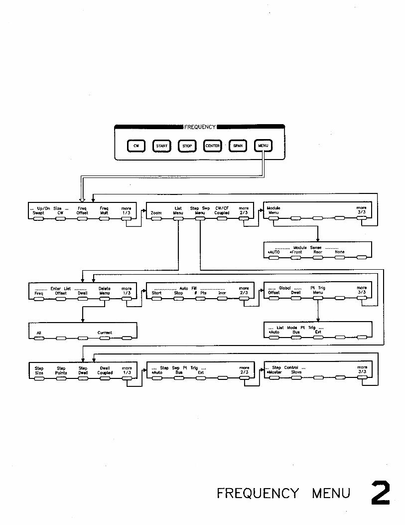
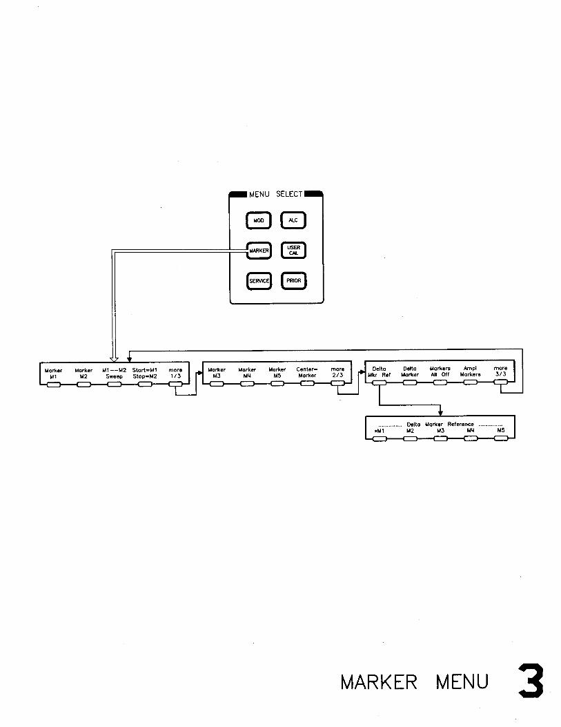
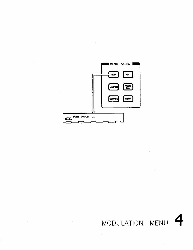
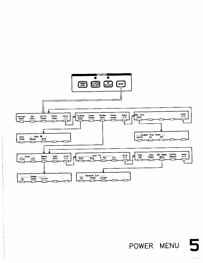

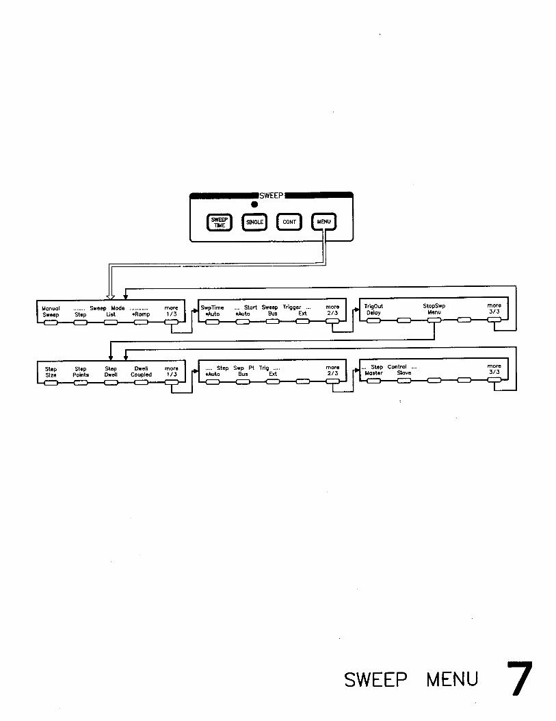

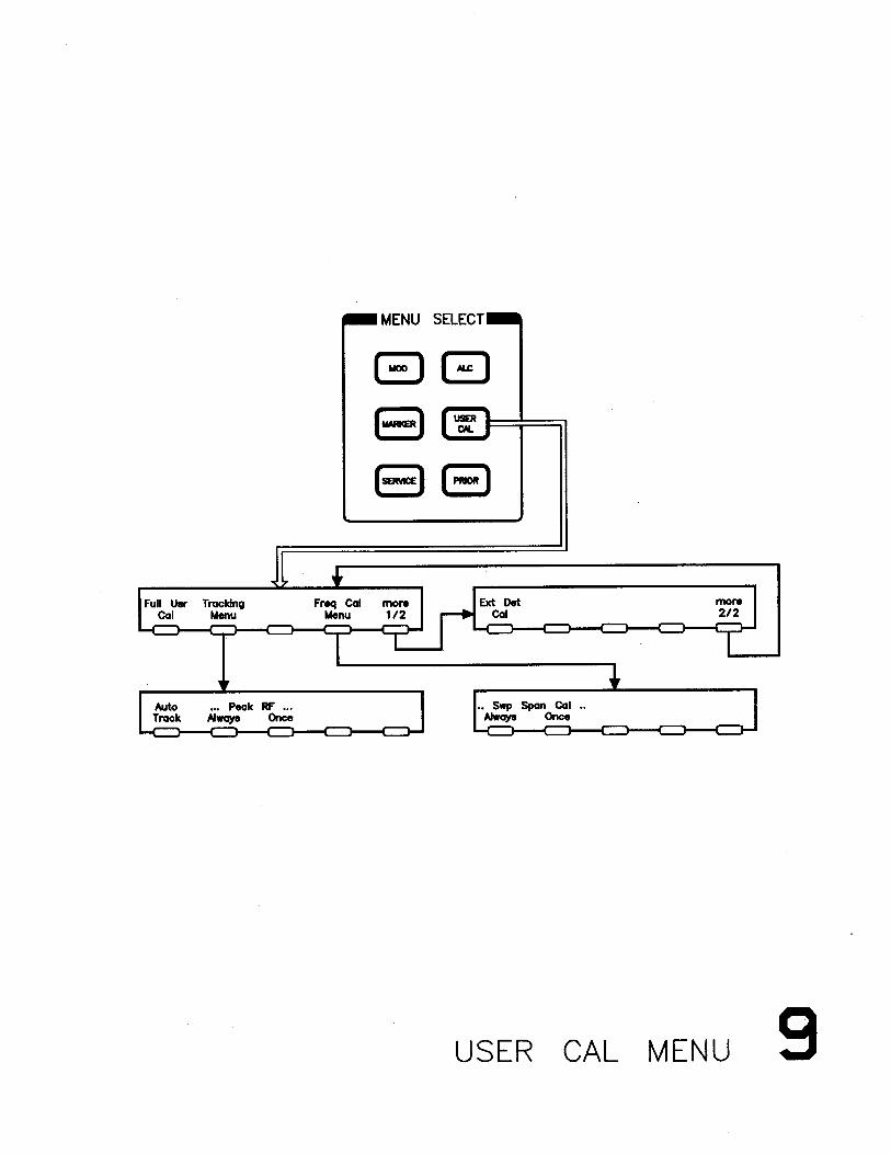

2c
Specifications
This section lists the speci�cations for the Agilent 8360 B-Seriesswept signal generator. In a e�ort to improve these swept signalgenerators, Agilent Technologies has made changes to this productwhich are identi�ed with changes in the serial number pre�x.
To check if your swept signal generator speci�cations are the same asthose listed in this section:
1. Locate your instrument model number and serial pre�x number inthe \Instrument History Changes" table in Chapter 5.
2. Check the right column of this table to determine whether anychanges apply to your instrument's model number/serial pre�xnumber combination.
3. If a change is listed, check this change to determine ifspeci�cations other than those listed in this section apply. Thechanges are included in Chapter 5.
Speci�cations describe warranted instrument performance over the 0 to +55 �Ctemperature range except as noted otherwise. Speci�cations apply after full usercalibration and in coupled attenuator mode of operation (ALC level greater than�10 dBm). Supplemental characteristics, denoted typical or nominal, are intended toprovide information useful in applying the instrument, but are non-warrantedparameters.
Specifications 2c-1

Frequency
Range Agilent 83620B: 10 MHz to 20 GHzAgilent 83622B: 2 to 20 GHzAgilent 83623B: 10 MHz to 20 GHz High PowerAgilent 83624B: 2 to 20 GHz High PowerAgilent 83630B: 10 MHz to 26.5 GHzAgilent 83640B: 10 MHz to 40 GHzAgilent 83650B: 10 MHz to 50 GHz
Resolution Standard: 1 kHzOption 008: 1 Hz
Frequency Bands(for CW signals)
Band Frequency Range n
0 10 MHz to < 2 GHz 11 2 GHz to < 7 GHz 12 7 GHz to < 13.5 GHz 23 13.5 GHz to < 20 GHz 34 20 GHz to < 26.5 GHz1 45 26.5 GHz to < 33.5 GHz2 66 33.5 GHz to < 38 GHz3 67 38 GHz to 50 GHz 8
1 This band is 20 GHz to < 25.5 GHz on the 83640B.
2 This band is 25.5 GHz to < 32 GHz on the 83640B.
3 This band is 32 GHz to < 40 GHz on the 83640B.
Frequency Modes:
CW and Manual Sweep Accuracy: Same as time base
Switching TimeFor Steps Within a Frequency Band:15 ms + (step size/1 GHz) � 5 msMaximum, or Across Band Switch Points: 50 msStep or List Modes within a frequency band:5 ms + (step size/1 GHz) � 5 ms1
1 Frequencies < 2 GHz, switching time = 6 ms + (step size/1 GHz) � 5 ms.
2c-2 Specifications
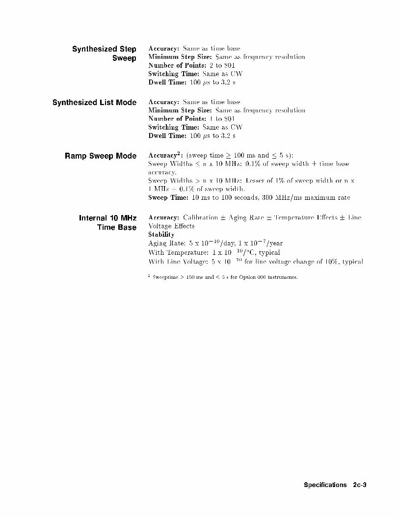
Synthesized StepSweep
Accuracy: Same as time baseMinimum Step Size: Same as frequency resolutionNumber of Points: 2 to 801Switching Time: Same as CWDwell Time: 100 �s to 3.2 s
Synthesized List Mode Accuracy: Same as time baseMinimum Step Size: Same as frequency resolutionNumber of Points: 1 to 801Switching Time: Same as CWDwell Time: 100 �s to 3.2 s
Ramp Sweep Mode Accuracy2: (sweep time � 100 ms and � 5 s):Sweep Widths � n x 10 MHz: 0.1% of sweep width � time baseaccuracy.Sweep Widths > n x 10 MHz: Lesser of 1% of sweep width or n x1 MHz + 0.1% of sweep width.Sweep Time: 10 ms to 100 seconds, 300 MHz/ms maximum rate
Internal 10 MHzTime Base
Accuracy: Calibration � Aging Rate � Temperature E�ects � LineVoltage E�ectsStabilityAging Rate: 5 x 10�10/day, 1 x 10�7/year
With Temperature: 1 x 10�10/�C, typical
With Line Voltage: 5 x 10�10 for line voltage change of 10%, typical
2 Sweeptime � 150 ms and � 5 s for Option 006 instruments.
Specifications 2c-3

RF Output
Output PowerMaximum Leveled3 Standard Option 006
83620B, 83622B +13 +1383623B +17 +1783624B +20 +1783630B
Output Frequencies < 20 GHz +13 +13Output Frequencies � 20 GHz +10 +10
83640BOutput Frequencies < 26.5 GHz +10 +10Output Frequencies > 26.5 GHz +6 +6
83650B
Output Frequencies < 26.5 GHz +10 +10Output Frequencies � 26.5 GHz and < 40 GHz +5 +5Output Frequencies � 40 GHz +2.5 +2.5
With attenuator (Option 001): Minimum settable output power is �110 dBm.Maximum leveled output power is reduced by 1.5 dB to 20 GHz, 2.0 dB above20 GHz, and 2.5 dB above 40 GHz.
Minimum SettableStandard: �20 dBm Option 001: �110 dBmResolution: 0.02 dBSwitching Time: (without attenuator change): 10 ms, typicalTemperature Stability: 0.01 dB/�C, typical
3 Speci�cation applies over the 0 to 35 �C temperature range (0 to 25 �C for outputfrequencies > 20 GHz). Maximum leveled output power over the 35 to 55 �Ctemperature range typically degrades by less than 2 dB.
2c-4 Specifications

Accuracy (dB)4
Speci�cations apply in CW, step, list, manual sweep, and ramp sweepmodes of operation.
Frequency (GHz)
Power < 2.0 � 2.0 and � 20 > 2.0 and � 40 > 40
> +10 dBm �1.2 �1.3
> �10 dBm5 �0.6 �0.7 �0.9 �1.7
> �60 dBm �0.9 �1.0 �1.2 �2.0
� �60 dBm �1.4 �1.5 �1.7 �2.5
Flatness (dB)
Speci�cations apply in CW, step, list, manual sweep, and ramp sweepmodes of operation.
Frequency (GHz)
Power < 2.0 � 2.0 and � 20 > 2.0 and � 40 > 40
> +10 dBm �0.9 �1.0
> �10 dBm5 �0.5 �0.6 �0.8 �1.5
> �60 dBm �0.7 �0.8 �1.0 �1.7
� �60 dBm �1.1 �1.2 �1.4 �2.1
4 Speci�cation applies over the 15 to 35 �C temperature range for output frequencies< 50 MHz.
5 Speci�cation applies over the 15 to 35 �C temperature range and are degraded 0.3 dBoutside of that range.
Specifications 2c-5
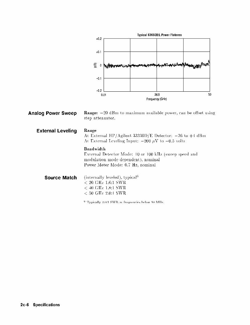
Analog Power Sweep Range: �20 dBm to maximum available power, can be o�set usingstep attenuator.
External Leveling RangeAt External HP/Agilent 33330D/E Detector: �36 to +4 dBmAt External Leveling Input: �200 �V to �0.5 volts
BandwidthExternal Detector Mode: 10 or 100 kHz (sweep speed andmodulation mode dependent), nominalPower Meter Mode: 0.7 Hz, nominal
Source Match (internally leveled), typical6
< 20 GHz 1.6:1 SWR< 40 GHz 1.8:1 SWR< 50 GHz 2.0:1 SWR
6 Typically 2.0:1 SWR at frequencies below 50 MHz.
2c-6 Specifications
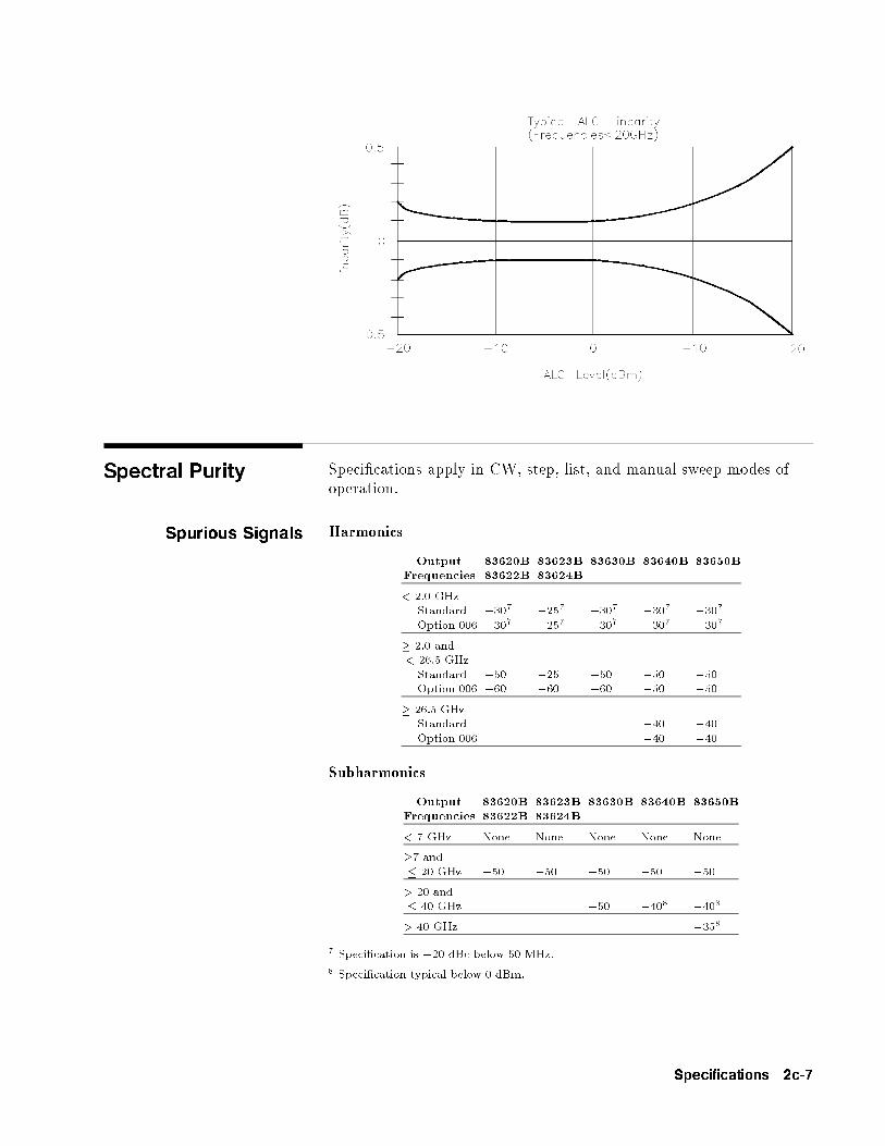
Spectral Purity Speci�cations apply in CW, step, list, and manual sweep modes ofoperation.
Spurious Signals Harmonics
OutputFrequencies
83620B83622B
83623B83624B
83630B 83640B 83650B
< 2.0 GHzStandard �307 �257 �307 �307 �307
Option 006 �307 �257 �307 �307 �307
� 2.0 and< 26.5 GHzStandard �50 �25 �50 �50 �50Option 006 �60 �60 �60 �50 �50
� 26.5 GHzStandard �40 �40Option 006 �40 �40
Subharmonics
OutputFrequencies
83620B83622B
83623B83624B
83630B 83640B 83650B
< 7 GHz None None None None None
�7 and� 20 GHz �50 �50 �50 �50 �50
> 20 and� 40 GHz �50 �408 �408
> 40 GHz �358
7 Speci�cation is �20 dBc below 50 MHz.
8 Speci�cation typical below 0 dBm.
Specifications 2c-7

Non{Harmonically Related
Output Frequencies:
< 2.0 GHz9 �60� 2.0 and < 20 GHz �60� 20 GHz and � 26.5 GHz �58> 26.5 and � 40 GHz �54> 40 GHz �52
9 Speci�cation applies at output levels 0 dBm and below.
2c-8 Specifications
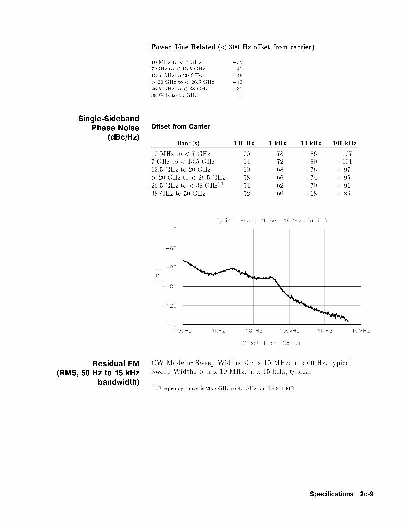
Power{Line Related (< 300 Hz o�set from carrier)
10 MHz to < 7 GHz �557 GHz to < 13.5 GHz �4913.5 GHz to 20 GHz �45> 20 GHz to < 26.5 GHz �4326.5 GHz to < 38 GHz10 �3938 GHz to 50 GHz �37
Single-SidebandPhase Noise
(dBc/Hz)
Offset from Carrier
Band(s) 100 Hz 1 kHz 10 kHz 100 kHz
10 MHz to < 7 GHz �70 �78 �86 �1077 GHz to < 13.5 GHz �64 �72 �80 �10113.5 GHz to 20 GHz �60 �68 �76 �97> 20 GHz to < 26.5 GHz �58 �66 �74 �9526.5 GHz to < 38 GHz10 �54 �62 �70 �9138 GHz to 50 GHz �52 �60 �68 �89
Residual FM(RMS, 50 Hz to 15 kHz
bandwidth)
CW Mode or Sweep Widths � n x 10 MHz: n x 60 Hz, typicalSweep Widths > n x 10 MHz: n x 15 kHz, typical
10 Frequency range is 26.5 GHz to 40 GHz on the 83640B.
Specifications 2c-9

Modulation
Pulse Pulse modulation speci�cations apply for output frequencies400 MHz and above.
Standard Option 006On/O� Ratio11 80 dB 80 dBRise/Fall Times 25 ns 10 nsMinimum WidthInternally Leveled 1 �s 1 �sSearch Mode
Output Frequencies < 2.0 GHz 50 ns 50 nsOutput Frequencies � 2.0 GHz 50 ns 15 ns
ALC O� ModeOutput Frequencies < 2.0 GHz 50 ns 50 nsOutput Frequencies � 2.0 GHz 50 ns 15 ns
Minimum Repetition FrequencyInternally leveled 10 Hz 10 HzSearch Mode DC DCALC O� Mode DC DCLevel Accuracy(dB, relative to CW level)Widths � 1 �s �0.3 �0.3Widths < 1 �s (Search Mode) �0.5, typical �0.5, typicalVideo FeedthroughOutput Frequencies < 2.0 GHz
Power Levels � 10 dBm 2% 2%Power Levels > 10 dBm 5% 5%
Output Frequencies � 2.0 GHz83620B/22B/30B 0.2% 1%83623B/24B/40B/50B 1% 1%
Overshoot, Ringing 15%, typical 10%, typicalDelay12
Output Frequencies < 2.0 GHz 80 ns, typical 80 ns, typicalOutput Frequencies � 2.0 GHz 80 ns, typical 60 ns, typicalCompressionOutput Frequencies < 2.0 GHz �10 ns, typical �10 ns, typicalOutput Frequencies � 2.0 GHz �10 ns, typical �5 ns, typical
11 In the 83623B/24B, speci�cation applies at ALC levels 0 dBm and above, and overthe 20 to 55 �C temperature range. Speci�cation degrades 5 dB below 20 �C, and1 dB per dB below ALC level 0 dBm in those models.
12 Option 002 adds 30 ns delay and �5 ns pulse compression for external pulse inputs.
2c-10 Specifications

Internal Pulse GeneratorWidth Range: 1 �s to 65 msPeriod Range: 2 �s to 65 msResolution: 1 �s
AM and Scan Bandwidth (3 dB, 30% depth, modulation peaks 3 dB belowmaximum rated power):DC to 100 kHz (typically DC to 300 kHz)
Modulation Depth(ALC levels noted, can be o�set using step attenuator)Normal Mode: �20 dBm to 1 dB below maximum available powerDeep Mode13, 15: 50 dB below maximum available powerUnleveled Mode14, 15: 50 dB below maximum available power
SensitivityLinear: 100%/voltAccuracy (1 kHz rate, 30% depth, normal mode): 5%Exponential: 10 dB/voltAccuracy (Normal Mode): 0.25 dB �5% of depth in dB
Incidental Phase Modulation (30% depth): 0.2 radians peak, typical
Incidental FM: Incidental phase modulation x modulation rate
13 Deep mode o�ers reduced distortion for very deep AM. Waveform is DC-coupled andfeedback-leveled at ALC levels above �13 dBm. At ALC levels below �13 dBm, outputis DC-controllable, but subject to typical sample-and-hold drift of 0.25 dB/second.
14 The 8360 has two unleveled modes, ALC o� and search. In ALC o� mode, themodulator drive can be controlled from the front panel to vary quiescent RF outputlevel. In search mode, the instrument microprocessor momentarily closes the ALC loopto �nd the modulator drive setting necessary to make the quiescent RF output levelequal to an entered value, then opens the ALC loop while maintaining that modulatordrive setting. Neither of these modes is feedback leveled.
15 Modulation depth is 40 dB below maximum available power for frequencies > 20 GHzon 83640B and 83650B.
Specifications 2c-11

FM Locked ModeMaximum Deviation: �8 MHzRates (3 dB bandwidth, 500 kHz deviation): 100 kHz to 8 MHzMaximum Modulation Index (deviation/rate): n x 5
Unlocked ModeMaximum DeviationAt rates � 100 Hz: �75 MHzAt rates > 100 Hz: �8 MHzRates (3 dB bandwidth, 500 kHz deviation): DC to 8 MHz
Sensitivity100 kHz, 1 MHz, or 10 MHz/volt, switchableAccuracy (1 MHz rate, 1 MHz deviation): 10%
SimultaneousModulations
Full AM bandwidth and depth is typically available at any pulserate or width. FM is completely independent of AM and pulsemodulation.
2c-12 Specifications

Internal ModulationGeneratorOption 002
AM, FM Internal Waveforms: sine, square, triangle, ramp, noiseRateRangeSine: 1 Hz to 1 MHzSquare, triangle, ramp: 1 Hz to 100 kHzResolution: 1 HzDepth, deviationRange: same as base instrumentResolution: 0.1%Accuracy: same as base instrument
Pulse Modes: free-run, gated, triggered, delayedPeriod range: 300 ns to 400 msWidth Range: 25 ns to 400 msResolution: 25 nsAccuracy: 5 nsVideo delayInternal sync pulse: 0 to 400 msExternally-supplied sync pulse: 225 to 400 ms
Modulation Meter Accuracy (rates � 100 kHz): 5% of range
Specifications 2c-13
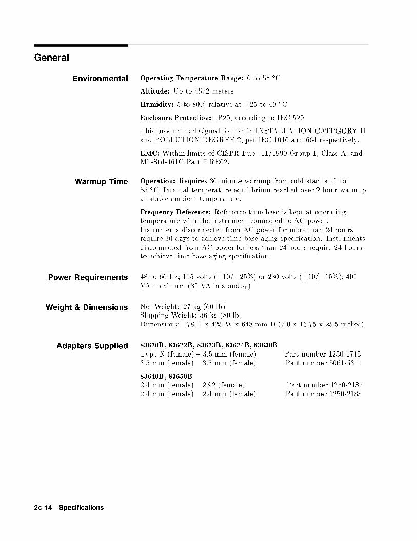
General
Environmental Operating Temperature Range: 0 to 55 �C
Altitude: Up to 4572 meters
Humidity: 5 to 80% relative at +25 to 40 �C
Enclosure Protection: IP20, according to IEC 529
This product is designed for use in INSTALLATION CATEGORY IIand POLLUTION DEGREE 2, per IEC 1010 and 664 respectively.
EMC: Within limits of CISPR Pub. 11/1990 Group 1, Class A, andMil-Std-461C Part 7 RE02.
Warmup Time Operation: Requires 30 minute warmup from cold start at 0 to55 �C. Internal temperature equilibrium reached over 2 hour warmupat stable ambient temperature.
Frequency Reference: Reference time base is kept at operatingtemperature with the instrument connected to AC power.Instruments disconnected from AC power for more than 24 hoursrequire 30 days to achieve time base aging speci�cation. Instrumentsdisconnected from AC power for less than 24 hours require 24 hoursto achieve time base aging speci�cation.
Power Requirements 48 to 66 Hz; 115 volts (+10/�25%) or 230 volts (+10/�15%); 400VA maximum (30 VA in standby)
Weight & Dimensions Net Weight: 27 kg (60 lb)Shipping Weight: 36 kg (80 lb)Dimensions: 178 H x 425 W x 648 mm D (7.0 x 16.75 x 25.5 inches)
Adapters Supplied 83620B, 83622B, 83623B, 83624B, 83630BType-N (female) { 3.5 mm (female) Part number 1250-17453.5 mm (female) { 3.5 mm (female) Part number 5061-5311
83640B, 83650B2.4 mm (female) { 2.92 (female) Part number 1250-21872.4 mm (female) { 2.4 mm (female) Part number 1250-2188
2c-14 Specifications
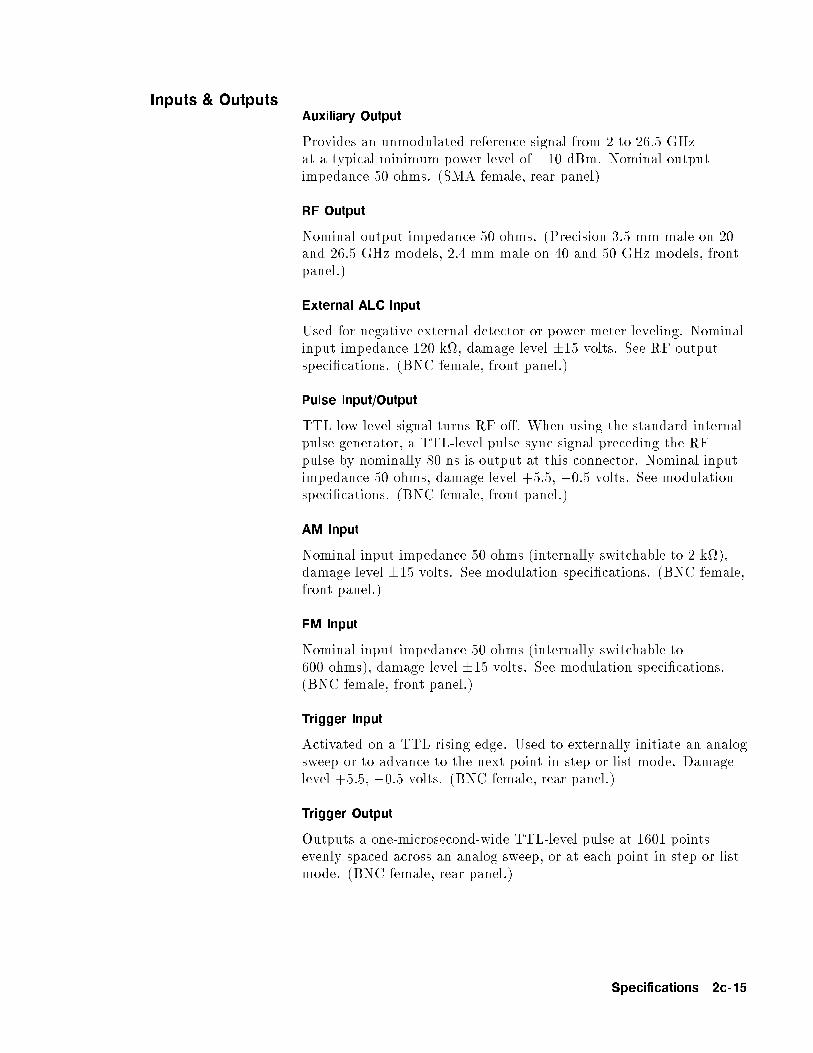
Inputs & OutputsAuxiliary Output
Provides an unmodulated reference signal from 2 to 26.5 GHzat a typical minimum power level of �10 dBm. Nominal outputimpedance 50 ohms. (SMA female, rear panel)
RF Output
Nominal output impedance 50 ohms. (Precision 3.5 mm male on 20and 26.5 GHz models, 2.4 mm male on 40 and 50 GHz models, frontpanel.)
External ALC Input
Used for negative external detector or power meter leveling. Nominalinput impedance 120 k, damage level �15 volts. See RF outputspeci�cations. (BNC female, front panel.)
Pulse Input/Output
TTL-low-level signal turns RF o�. When using the standard internalpulse generator, a TTL-level pulse sync signal preceding the RFpulse by nominally 80 ns is output at this connector. Nominal inputimpedance 50 ohms, damage level +5.5, �0.5 volts. See modulationspeci�cations. (BNC female, front panel.)
AM Input
Nominal input impedance 50 ohms (internally switchable to 2 k),damage level �15 volts. See modulation speci�cations. (BNC female,front panel.)
FM Input
Nominal input impedance 50 ohms (internally switchable to600 ohms), damage level �15 volts. See modulation speci�cations.(BNC female, front panel.)
Trigger Input
Activated on a TTL rising edge. Used to externally initiate an analogsweep or to advance to the next point in step or list mode. Damagelevel +5.5, �0.5 volts. (BNC female, rear panel.)
Trigger Output
Outputs a one-microsecond-wide TTL-level pulse at 1601 pointsevenly spaced across an analog sweep, or at each point in step or listmode. (BNC female, rear panel.)
Specifications 2c-15
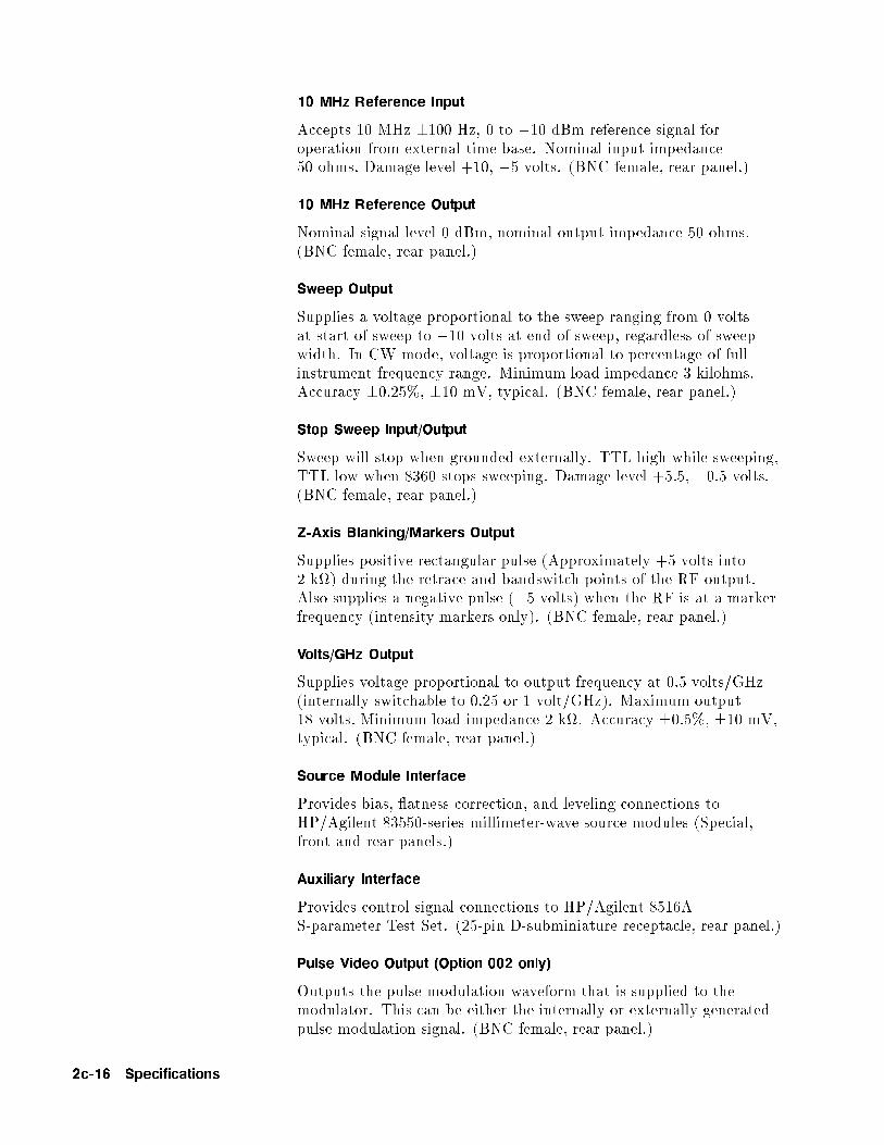
10 MHz Reference Input
Accepts 10 MHz �100 Hz, 0 to +10 dBm reference signal foroperation from external time base. Nominal input impedance50 ohms. Damage level +10, �5 volts. (BNC female, rear panel.)
10 MHz Reference Output
Nominal signal level 0 dBm, nominal output impedance 50 ohms.(BNC female, rear panel.)
Sweep Output
Supplies a voltage proportional to the sweep ranging from 0 voltsat start of sweep to +10 volts at end of sweep, regardless of sweepwidth. In CW mode, voltage is proportional to percentage of fullinstrument frequency range. Minimum load impedance 3 kilohms.Accuracy �0.25%, �10 mV, typical. (BNC female, rear panel.)
Stop Sweep Input/Output
Sweep will stop when grounded externally. TTL-high while sweeping,TTL-low when 8360 stops sweeping. Damage level +5.5, �0.5 volts.(BNC female, rear panel.)
Z-Axis Blanking/Markers Output
Supplies positive rectangular pulse (Approximately +5 volts into2 k) during the retrace and bandswitch points of the RF output.Also supplies a negative pulse (�5 volts) when the RF is at a markerfrequency (intensity markers only). (BNC female, rear panel.)
Volts/GHz Output
Supplies voltage proportional to output frequency at 0.5 volts/GHz(internally switchable to 0.25 or 1 volt/GHz). Maximum output18 volts. Minimum load impedance 2 k. Accuracy �0.5%, �10 mV,typical. (BNC female, rear panel.)
Source Module Interface
Provides bias, atness correction, and leveling connections toHP/Agilent 83550-series millimeter-wave source modules (Special,front and rear panels.)
Auxiliary Interface
Provides control signal connections to HP/Agilent 8516AS-parameter Test Set. (25-pin D-subminiature receptacle, rear panel.)
Pulse Video Output (Option 002 only)
Outputs the pulse modulation waveform that is supplied to themodulator. This can be either the internally or externally generatedpulse modulation signal. (BNC female, rear panel.)
2c-16 Specifications
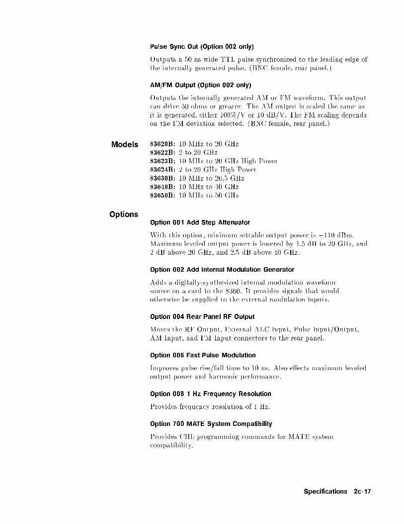
Pulse Sync Out (Option 002 only)
Outputs a 50 ns wide TTL pulse synchronized to the leading edge ofthe internally-generated pulse. (BNC female, rear panel.)
AM/FM Output (Option 002 only)
Outputs the internally-generated AM or FM waveform. This outputcan drive 50 ohms or greater. The AM output is scaled the same asit is generated, either 100%/V or 10 dB/V. The FM scaling dependson the FM deviation selected. (BNC female, rear panel.)
Models 83620B: 10 MHz to 20 GHz83622B: 2 to 20 GHz83623B: 10 MHz to 20 GHz High Power83624B: 2 to 20 GHz High Power83630B: 10 MHz to 26.5 GHz83640B: 10 MHz to 40 GHz83650B: 10 MHz to 50 GHz
OptionsOption 001 Add Step Attenuator
With this option, minimum settable output power is �110 dBm.Maximum leveled output power is lowered by 1.5 dB to 20 GHz, and2 dB above 20 GHz, and 2.5 dB above 40 GHz.
Option 002 Add Internal Modulation Generator
Adds a digitally-synthesized internal modulation waveformsource-on-a-card to the 8360. It provides signals that wouldotherwise be supplied to the external modulation inputs.
Option 004 Rear Panel RF Output
Moves the RF Output, External ALC Input, Pulse Input/Output,AM Input, and FM Input connectors to the rear panel.
Option 006 Fast Pulse Modulation
Improves pulse rise/fall time to 10 ns. Also e�ects maximum leveledoutput power and harmonic performance.
Option 008 1 Hz Frequency Resolution
Provides frequency resolution of 1 Hz.
Option 700 MATE System Compatibility
Provides CIIL programming commands for MATE systemcompatibility.
Specifications 2c-17

Option 806 Rack Slide Kit
Used to rack mount 8360 while permitting access to internal spaces.
Option 908 Rack Flange Kit
Used to rack mount 8360 without front handles.
Option 910 Extra Operating & Service Guides
Provides a second copy of operating and service guides.
Option 013 Rack Flange Kit
Used to rack mount 8360 with front handles. Front handles arestandard on the 8360.
Option W30 Two Years Additional Return{To{Agilent Service
Does not include biennial calibration.
2c-18 Specifications
3
Installation
This chapter provides installation instructions for the Agilent 8360B-Series swept signal generator and its accessories. It also providesinformation about initial inspection, damage claims, preparation foruse, packaging, storage, and shipment.
CAUTION This product is designed for use in Installation Category II andPollution Degree 2 per IEC 1010 and 664, respectively.
Initial Inspection Inspect the shipping container for damage. If the shipping containeror cushioning material is damaged, it should be kept until thecontents of the shipment have been checked for completeness andthe swept signal generator has been checked mechanically andelectrically. The contents of the shipment should agree with theitems noted on the packing slip. Procedures for checking the basicoperation of the swept signal generator are in Chapter 4, \Operator'sCheck and Routine Maintenance". You will �nd procedures forchecking electrical performance in the \Performance Tests" chapterof your Agilent Technologies 8360 B-Series Swept Signal Generator/8360 L-Series Swept CW Generator Service Guide.
If there is any electrical or mechanical defect, or if the shipmentis incomplete, notify the nearest Agilent Technologies o�ce. If theshipping container is damaged, or if the cushioning material showssigns of stress, notify the carrier as well as the Agilent Technologieso�ce. Keep the shipping material for the carrier's inspection. TheAgilent o�ce will arrange for repair or replacement without waitingfor a claim settlement.
Installation 3-1

Equipment Supplied All 8360 B-Series swept signal generators are sent from the factorywith the following basic accessories:
Rack handles (mounted)
Power cord
Software package
A set of manuals
The following adapters are also shipped with the swept signalgenerators:
Table 3-1.
Adapter Descriptions and Part Numbers Shipped with
Each Agilent Swept Signal Generator Model
83620B/83622B/83623B/83624B/83630B
Type-N (F) to 3.5 mm (F) 1250-1745
3.5 mm (F) to 3.5 mm (F) 5061-5311
83640B/83650B
2.4 mm (F) to K (F) 1250-2187
2.4 mm (F) to 2.4 mm (F) 1250-2188
Options Available There are several options available on the 8360 B-Series sweptsignal generators. For descriptive information on all of the optionsavailable, refer to Chapter 2c, \Speci�cations". For installationinformation on the rack mounting kits, refer to later paragraphs inthis chapter. For information on retro�tting options, refer to the\Option Retro�ts" chapter in the Agilent Technologies 8360 B-SeriesSwept Signal Generator/8360 L-Series Swept CW Generator ServiceGuide.
3-2 Installation

Preparation for Use
Enclosure Protection Install the instrument according to the enclosure protection provided.
This instrument does not protect against the ingress of water.
This instrument protects against �nger access to hazardous partswithin the enclosure.
Power Requirements The 8360 B-Series swept signal generators require a power source of115 V (+10/�25%) or 230 V (+10/�15%), 48 to 66 Hz, single-phase.Power consumption is 400 VA maximum (30 VA in standby).
Line Voltage and FuseSelection
The swept signal generator is provided with a voltage selector(located on the rear panel) to match the swept signal generator tothe ac line voltage available at the site of installation. Both the lineselector and fuse were selected at the factory to match the ac linevoltage expected to be found at the shipping destination. Verify thatthe voltage selector has been set to the correct line voltage beforeconnecting power to the swept signal generator.
WARNING For continued protection against fire hazard replace line fuse only with
same type and rating. The use of other fuses or material is prohibited.
Refer to the \Routine Maintenance" in Chapter 4 for information onchanging fuses.
CAUTION Before switching on this product, make sure that the line voltageselector switch is set to the voltage of the power supply and thecorrect fuse is installed. Assure the supply voltage is in the speci�edrange.
Installation 3-3

Power Cable In accordance with international safety standards, this instrumentis equipped with a three-wire power cable. When connected to anappropriate power line outlet, this cable grounds the instrumentcabinet. Figure 3-1 shows the styles of plugs available on powercables supplied with Agilent Technologies instruments. The partnumbers indicated are part numbers for the complete powercable/plug set. The speci�c type of power cable/plug shipped withthe instrument depends upon the country of shipment destination.
WARNING This is a Safety Class I product (provided with a protective earthing
ground incorporated in the power cord). The mains plug shall only be
inserted in a socket outlet provided with a protective earth contact.
Any interruption of the protective conductor, inside or outside the
instrument, is likely to make the instrument dangerous. Intentional
interruption is prohibited.
CAUTION Always use the three-prong ac power cord supplied with thisinstrument. Failure to ensure adequate earth grounding by not usingthis cord may cause instrument damage.
The o�set prong of the three-prong connector is the groundingpin. The protective grounding feature is preserved when operatingthe swept signal generator from a two contact outlet by using athree-prong to a two-prong adapter and connecting the green wire ofthe adapter to ground. An adapter is available (for US connectorsonly) as part number 1251-0048.
Install the instrument so that the detachable power cord is readilyidenti�able and is easily reached by the operator. The detachablepower cord is the instrument disconnecting device. It disconnectsthe mains circuits from the mains supply before other parts of theinstrument. The front panel switch is only a standby switch and isnot a LINE switch. Alternately, an externally installed switch orcircuit breaker (which is readily identi�able and is easily reached bythe operator) may be used as a disconnecting device.
3-4 Installation
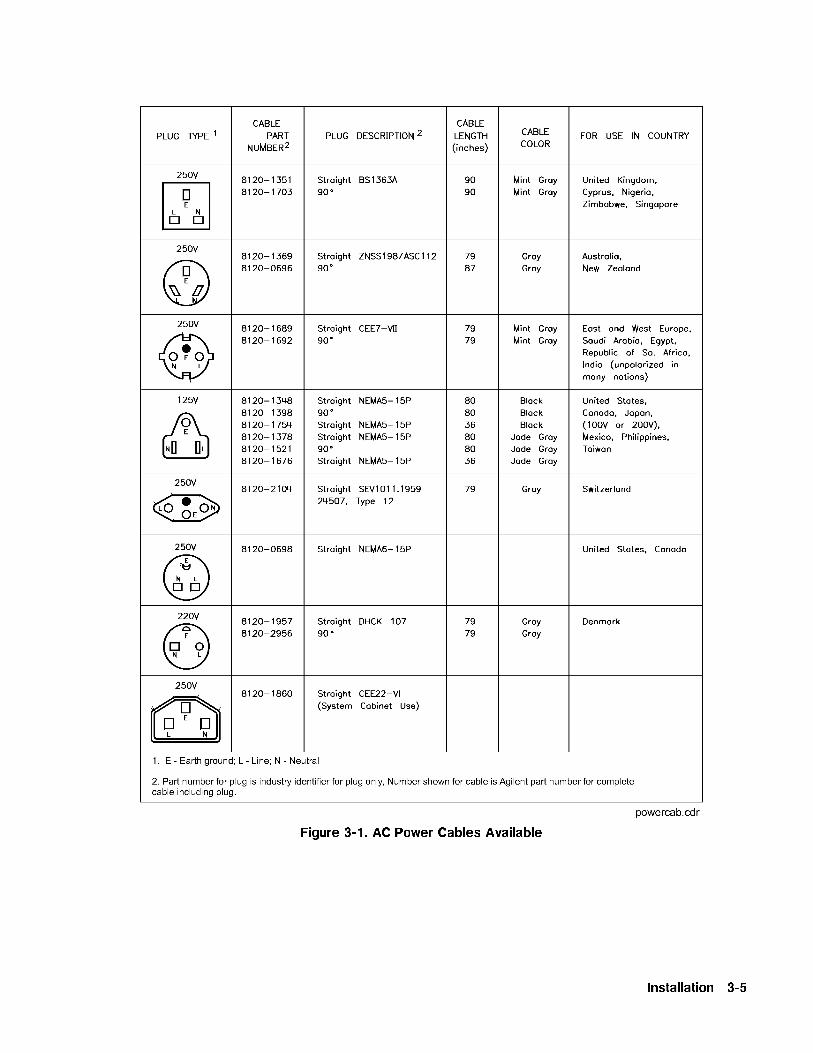
Figure 3-1. AC Power Cables Available
Installation 3-5

Language Selection You can operate the swept signal generator using one of threeexternal interface languages: SCPI, Analyzer language, or CIIL(Option 700).
How to View or Change a Language Selection from the Front Panel
Note To set a programming language from the front panel, the instrumentlanguage on the rear panel GPIB switch (L1, L2, and L3 shown inFigure 3-2) must be set to 7 (all 1s).
The GPIB menu provides access to the swept signal generator'sprogramming language:
1. Press SYSTEM �MENU�.2. Select
NNNNNNNNNNNNNNNNNNNNNNNNNNNNNGPIB Menu .
3. The swept signal generator displays the threelanguage softkeys:
NNNNNNNNNNNNNNNNNNNNNNNNNNNNNNNNNNNNNNNNNNNNNNNNNNNNNNNNNNNNNNNNNNNNNNNNNNNNNProgramming Language SCPI ,NNNNNNNNNNNNNNNNNNNNNNNNNNNNNNNNNNNNNNNNNNNNNNNNNNNNNNNNNNNNNNNNNNNNNNNNNNNNNNNNNNNNNN
Programming Language Analyzr , andNNNNNNNNNNNNNNNNNNNNNNNNNNNNNNNNNNNNNNNNNNNNNNNNNNNNNNNNNNNNNNNNNNNNNNNNNNNNNProgramming Language CIIL . An asterisk indicatesthe selected language.
4. Select the desired softkey.
Remember If the swept signal generator displays Rear panel GPIB languagemust be 7 (111) in order to change current language (=XXX),the address on the rear panel GPIB switch (Figure 3-2) is set tosomething other than 7 (all 1s).
Note If the swept signal generator does not have Option 700, and youselect
NNNNNNNNNNNNNNNNNNNNNNNNNNNNNNNNNNNNNNNNNNNNNNNNNNNNNNNNNNNNNNNNNNNNPower Up Language CIIL , the instrument displays
*****OPTION NOT INSTALLED*****.
5. The asterisk indicates the selected softkey, and the swept signalgenerator displays LANG:XXXX, ADRS=XX, REV da mo yr.
How to Select a Language on an Instrument without a Front Panel
If your swept signal generator does not have a front panel, set therear panel GPIB switch (Figure 3-2) for the language you want. (SeeTable 3-2 for language addresses.)
Table 3-2. Language GPIB Addresses
Language GPIB Address(Decimal)
SCPI 0
Analyzer 1
CIIL 2
3-6 Installation
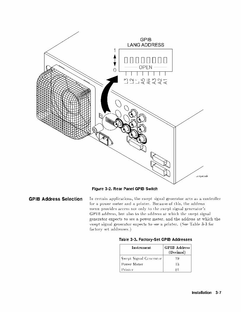
Figure 3-2. Rear Panel GPIB Switch
GPIB Address Selection In certain applications, the swept signal generator acts as a controllerfor a power meter and a printer. Because of this, the addressmenu provides access not only to the swept signal generator'sGPIB address, but also to the address at which the swept signalgenerator expects to see a power meter, and the address at which theswept signal generator expects to see a printer. (See Table 3-3 forfactory-set addresses.)
Table 3-3. Factory-Set GPIB Addresses
Instrument GPIB Address(Decimal)
Swept Signal Generator 19
Power Meter 13
Printer 01
Installation 3-7

How to View or Change an GPIB Address from the Front Panel
Note To set a GPIB address from the front panel, the instrument addresson the rear panel GPIB switch (Figure 3-2) must be set to 31 (all1s).
1. Press SYSTEM �MENU�.2. Select
NNNNNNNNNNNNNNNNNNNNNNNNNNNNNGPIB Menu
NNNNNNNNNNNNNNNNNNNNNNNNNNNNNAdrs Menu .
3. The swept signal generator displays the three address softkeys:NNNNNNNNNNNNNNNNNNNNNNNNNNNNN8360 Adrs ,
NNNNNNNNNNNNNNNNNNNNNNNNNNNNNNNNMeter Adrs , and
NNNNNNNNNNNNNNNNNNNNNNNNNNNNNNNNNNNNNNPrinter Adrs .
4. Select the desired softkey.5. The swept signal generator displays the address selected for that
instrument.6. If you want to change the address, use the keypad to enter the
desired address (0 to 30), then press �ENTER�.
Remember If the swept signal generator displays Rear panel GPIB address
must be 31 (11111) in order to change current address (=XX),the address on the rear panel GPIB switch (Figure 3-2) is set tosomething other than 31 (all 1s).
How to Prevent a Front Panel Change to a GPIB Address
To disable the address softkeys, set the instrument address on therear panel GPIB switch (Figure 3-2) to any address other than 31 (all1s).
How to Set the GPIB Address on a Swept Signal Generator without a
Front Panel
If your swept signal generator does not have a front panel, set theaddress on the rear panel GPIB switch (Figure 3-2) to the addressyou want (factory default is 19).
Mating Connectors All of the externally mounted connectors on the instrument arediscussed in \CONNECTORS" in Chapter 2. If you are interestedin the part number for a connector, see \Replaceable Parts" inthe Agilent Technologies 8360 B-Series Swept Signal Generator/8360 L-Series Swept CW Generator Service Guide.
10 MHz FrequencyReference Selectionand Warmup Time
To keep the internal timebase frequency reference oven at operatingtemperature, the swept signal generator must be connected to ac linepower. The swept signal generator requires approximately 30 minutesto warm up from a cold start before the OVEN display messagegoes o�. With a stable outside temperature, internal temperatureequilibrium is reached after approximately two hours. For additionalinformation on warmup times, see Chapter 2c, \Speci�cations".
3-8 Installation

Operating Environment Temperature. The swept signal generator may be operated inenvironments with temperatures from 0 to +55 �C.
Humidity. The swept signal generator may be operated inenvironments with humidity from 5 to 80% relative at +25 to40 �C. However, protect the swept signal generator from temperatureextremes, which can cause condensation within the instrument.
Altitude. The swept signal generator may be operated at pressurealtitudes up to 4572 meters (approximately 15,000 feet).
Cooling. The swept signal generator obtains all cooling air owby forced ventilation from the fan mounted on the rear panel.Information on cleaning the fan �lter is located in \RoutineMaintenance" in Chapter 4.
CAUTION Ensure that all air ow passages at the rear and sides of the sweptsignal generator are clear before installing the instrument in itsoperating environment. This is especially important in a rack mountcon�guration.
Installation 3-9

Chassis Kits
Rack Mount Slide Kit(Option 806)
Option 806 swept signal generators are supplied with rack mountslides and the necessary hardware to install them on the swept signalgenerator. The following table itemizes the parts in this kit.
Table 3-4. Rack Mount Slide Kit Contents
Quantity Description
Rack Mount Kit (Includes the following parts)
2 Rack Mount Flanges
8 Screws
Slide Kit (Includes the following parts)
2 Slide Assemblies
4 Screws (Inner Slide Assembly)
8 Screws (Outer Slide Assembly)
8 Nuts (Outer Slide Assembly)
Slide Adapter Kit (NON-HP , includes the following parts)
4 Adapter Brackets
4 Adapter Bar
8 Screws (Bracket to Bar)
8 Nuts (Bracket to Slide Assembly)
CAUTION Ventilation Requirements: When installing the instrument in acabinet, the convection into and out of the instrument must not berestricted. The ambient temperature (outside the cabinet) must beless than the maximum operating temperature of the instrumentby 4 �C for every 100 watts dissipated in the cabinet. If the totalpower dissipated in the cabinet is greater than 800 watts, then forcedconvection must be used.
3-10 Installation
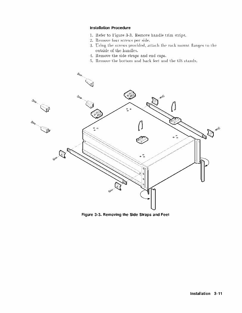
Installation Procedure
1. Refer to Figure 3-3. Remove handle trim strips.2. Remove four screws per side.3. Using the screws provided, attach the rack mount anges to the
outside of the handles.4. Remove the side straps and end caps.5. Remove the bottom and back feet and the tilt stands.
Figure 3-3. Removing the Side Straps and Feet
Installation 3-11

6. Refer to Figure 3-4. Remove the inner slide assemblies from theouter slide assemblies.
7. To secure the side covers in place, mount the inner slide assembliesto the instrument with the screws provided.
8. With the appropriate hardware, install the outer slide assembliesto the system enclosure.
9. Lift the swept signal generator into position. Align the inner andouter slide assemblies and slide the instrument into the rack.Realign the hardware as needed for smooth operation.
Figure 3-4. Chassis Slide Kit
3-12 Installation

Rack Flange Kit forSwept Signal
Generators withHandles Removed
(Option 908)
Option 908 swept signal generators are supplied with rack anges andthe necessary hardware to install them on the swept signal generatorafter removing the instrument handles. The following table itemizesthe parts in this kit.
Table 3-5.
Rack Flange Kit for Swept Signal Generators with
Handles Removed Contents
Quantity Description
2 Rack Mount Flanges
8 Screws
CAUTION Ventilation Requirements: When installing the instrument in acabinet, the convection into and out of the instrument must not berestricted. The ambient temperature (outside the cabinet) must beless than the maximum operating temperature of the instrumentby 4 �C for every 100 watts dissipated in the cabinet. If the totalpower dissipated in the cabinet is greater than 800 watts, then forcedconvection must be used.
Installation 3-13

Installation Procedure
1. Refer to Figure 3-5. Remove handle trim strips.2. Remove the four screws on each side that attach the handles to
the instrument; remove the handles.3. Using the screws provided, attach the rack mount anges to the
swept signal generator.4. Remove the bottom and back feet and the tilt stands before rack
mounting the instrument.
Figure 3-5. Rack Mount Flanges for Swept Signal Generators with Handles Removed
3-14 Installation
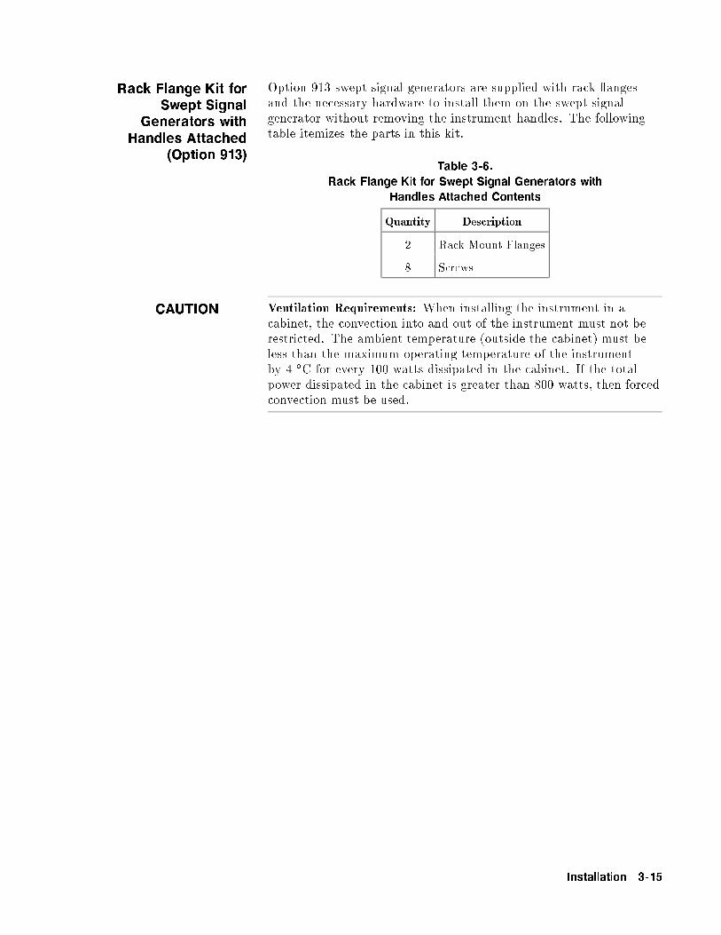
Rack Flange Kit forSwept Signal
Generators withHandles Attached
(Option 913)
Option 913 swept signal generators are supplied with rack angesand the necessary hardware to install them on the swept signalgenerator without removing the instrument handles. The followingtable itemizes the parts in this kit.
Table 3-6.
Rack Flange Kit for Swept Signal Generators with
Handles Attached Contents
Quantity Description
2 Rack Mount Flanges
8 Screws
CAUTION Ventilation Requirements: When installing the instrument in acabinet, the convection into and out of the instrument must not berestricted. The ambient temperature (outside the cabinet) must beless than the maximum operating temperature of the instrumentby 4 �C for every 100 watts dissipated in the cabinet. If the totalpower dissipated in the cabinet is greater than 800 watts, then forcedconvection must be used.
Installation 3-15
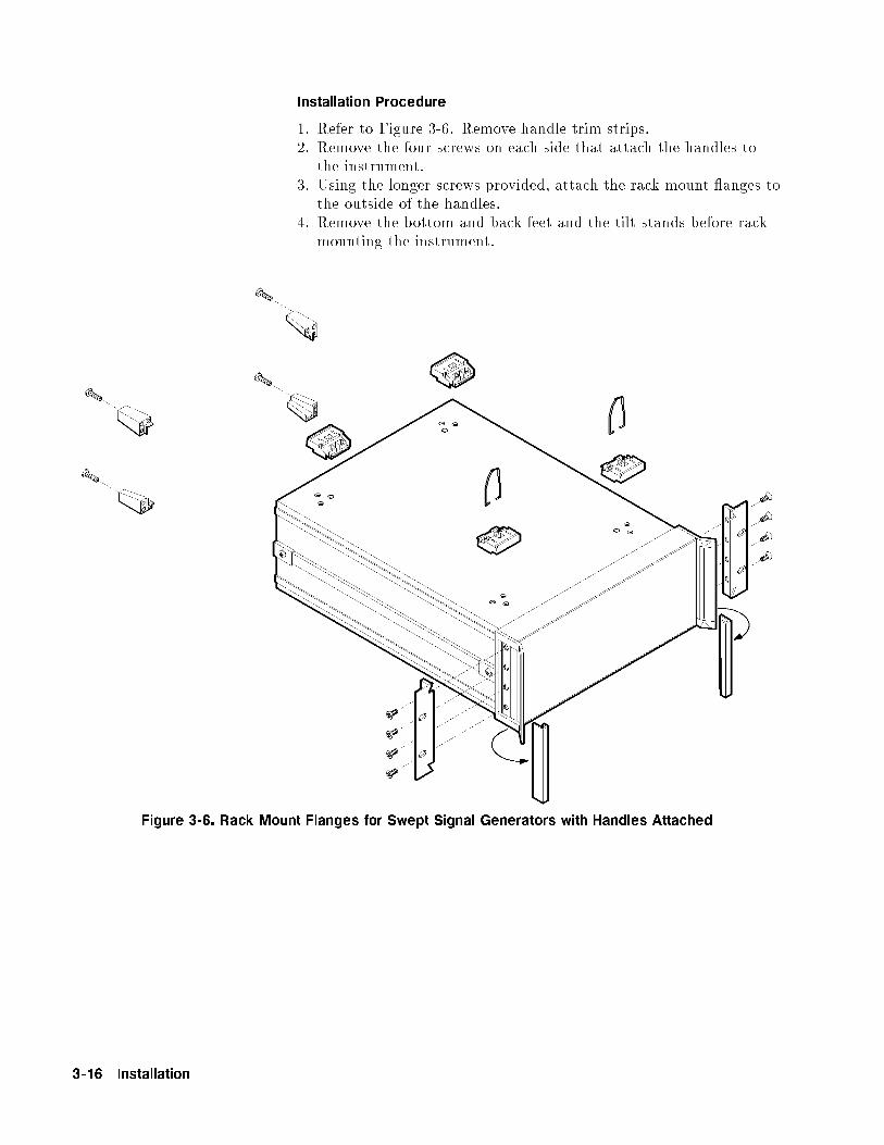
Installation Procedure
1. Refer to Figure 3-6. Remove handle trim strips.2. Remove the four screws on each side that attach the handles to
the instrument.3. Using the longer screws provided, attach the rack mount anges to
the outside of the handles.4. Remove the bottom and back feet and the tilt stands before rack
mounting the instrument.
Figure 3-6. Rack Mount Flanges for Swept Signal Generators with Handles Attached
3-16 Installation
Storage andShipment
Environment The swept signal generator may be stored or shipped within thefollowing limits:
Temperature �40 � to +75 �C.
Humidity 5% to 95% relative at 0 � to +40 �C.
Altitude Up to 15240 meters. Pressure approximately 50,000feet.
The swept signal generator should be protected from suddentemperature uctuations that can cause condensation.
Installation 3-17

Package the SweptSignal Generator for
Shipment
Use the following steps to package the swept signal generator forshipment to Agilent Technologies for service:
1. Fill in a service tag (available at the end of Chapter 4) and attachit to the instrument. Please be as speci�c as possible about thenature of the problem. Send a copy of any or all of the followinginformation:
Any error messages that appeared on the swept signal generatordisplayA completed Performance Test record from the service guide foryour instrumentAny other speci�c data on the performance of the swept signalgenerator
CAUTION Swept signal generator damage can result from using packagingmaterials other than those speci�ed. Never use styrene pellets in anyshape as packaging materials. They do not adequately cushion theinstrument or prevent it from shifting in the carton. Styrene pelletscause equipment damage by generating static electricity and bylodging in the swept signal generator fan.
2. Use the original packaging materials or a strong shipping containerthat is made of double-walled, corrugated cardboard with 159 kg(350 lb) bursting strength. The carton must be both large enoughand strong enough to accommodate the swept signal generatorand allow at least 3 to 4 inches on all sides of the swept signalgenerator for packing material.
3. Surround the instrument with at least 3 to 4 inches of packingmaterial, or enough to prevent the instrument from moving inthe carton. If packing foam is not available, the best alternativeis SD-240 Air CapTM from Sealed Air Corporation (Hayward,CA 94545). Air Cap looks like a plastic sheet covered with1-1/4 inch air-�lled bubbles. Use the pink Air Cap to reducestatic electricity. Wrap the instrument several times in thematerial to both protect the instrument and prevent it frommoving in the carton.
4. Seal the shipping container securely with strong nylon adhesivetape.
5. Mark the shipping container \FRAGILE, HANDLE WITHCARE" to ensure careful handling.
6. Retain copies of all shipping papers.
In any correspondence, refer to the swept signal generator bymodel number and full serial number.
3-18 Installation

ConvertingHP/Agilent 8340/41Systems to 8360B-Series Systems
The following paragraphs are intended to assist you in convertingexisting HP/Agilent 8340/8341-based systems to 8360 B-Series sweptsignal generator-based systems. Both manual and remote operationaldi�erences are addressed.
Manual operation topics are:
functional compatibility
front panel operation
conditions upon instrument preset
connections to other instruments
Remote operation topics are:
language compatibility
status structure
programming languages
Installation 3-19

Manual OperationCompatibility
The 8360 B-Series swept signal generators are designed to be,in all but very few cases, a complete feature superset of theHP/Agilent 8340/8341 synthesized sweepers. The most notableomissions are that the 8360 B-Series does not accept:
line triggers (ie. 50 or 60 Hz line frequency)
an external leveling input from positive diode detectors
Front Panel Operation
The 8360 B-Series uses a softkey menu driven approach towardaccessing instrument functions versus a front panel key or shift keysequence as with the HP/Agilent 8340/8341.
Instrument Preset Conditions. The factory de�ned presetconditions for the 8360 B-Series are identical to those for theHP/Agilent 8340/8341. The 8360 B-Series also allows you to de�nea di�erent set of preset conditions. Refer to \Changing the PresetParameters" in Chapter 1 for examples and more information.Table 3-7 illustrates the factory instrument preset conditions for the8360 B-Series and the HP/Agilent 8340/8341. An instrument presetturns o� all the functions and then sets the following:
Table 3-7.
Instrument Preset Conditions for the HP/Agilent
8360/8340/8341
Function Condition
Sweep Mode Full Span
Sweep Continuous/Auto
Trigger Free Run
Markers All O�
Modulation O�
Frequency Step Size 10% of span
Status Bytes Cleared
Leveling Internal
RF Output On
Power Level 0 dBm
Power Step Size 10 dB
Power Sweep/Slope 0 dB
Storage Registers Retain current values
GPIB Address Retains current value
Status Byte Mask Unchanged
Extended Status Byte Mask Unchanged
Language Mode Unchanged
3-20 Installation

System ConnectionsThe HP/Agilent 8510 Network Analyzer
The 8360 B-Series swept signal generator is compatible with anyHP/Agilent 8510 network analyzer with �rmware revision 4.0 orhigher. To upgrade �rmware for an existing HP/Agilent 8510,an HP/Agilent 11575C Revision 4.0 Upgrade Kit or anHP/Agilent 11575D Revision 5.0 Upgrade Kit is required.
HP/Agilent 8510 revisions prior to 6.0 (not inclusive) require thatyou use the following connections:
SWEEP OUTPUT
STOP SWEEP IN/OUT
GPIB INTERFACE
AUXILIARY INTERFACE
HP/Agilent 8510 revisions 6.0 and greater use the connections asdesignated on the rear panel of the swept signal generator. They are:
TRIGGER OUTPUT
STOP SWEEP IN/OUT
GPIB INTERFACE
AUXILIARY INTERFACE
The dedicated HP/Agilent 8510 versions of the 8360 (Agilent83621B, Agilent 83631B) may be con�gured to power-up to oneof two possible system languages, network analyzer language, orSCPI (Standard Commands for Programmable Instruments). Thiscon�guration is controlled via a switch located on the rear panel ofthe instrument. The factory default setting for this switch is networkanalyzer language at a GPIB address of 19. To interface with anetwork analyzer the language selected must be Analyzer language.Refer to earlier paragraphs in this chapter for the rear panel switchsettings.
Note Models other than the dedicated HP/Agilent 8510 versions are setat the factory for SCPI. To interface with a network analyzer thelanguage selected must be Analyzer language.
Installation 3-21
The HP/Agilent 8757C/E Scalar Network Analyzer
The connections between the analyzer and the 8360 B-Seriesare similar to the connections between the analyzer and theHP/Agilent 8340/8341. The 8360 B-Series di�ers from theHP/Agilent 8340/8341 in one connection only. It is unnecessary toconnect the modulator drive signal from the analyzer to the source.The 8360 B-Series internally produces the 27.8 kHz modulatedsignal necessary for AC mode measurements on the analyzer. Theconnections from the 8360 B-Series to the analyzer are:
Z-AXIS BLANK/MKRS
SWEEP OUTPUT
STOP SWEEP IN/OUT
GPIB Interface
Con�gure the general-purpose 8360 B-Series to GPIB address 19and network analyzer language for operation with the analyzer. Forinformation on selecting the instrument address and language refer toearlier paragraphs in this chapter.
The dedicated HP/Agilent 8510 versions (83621B, 83631B) of the8360 B-Series cannot be used with the HP/Agilent 8757C/E.
The HP/Agilent 83550 Series Millimeter-wave Source Modules
Refer to \Leveling with MM-wave Source Modules" in Chapter 1 forinformation and examples.
The HP/Agilent 8970B Noise Figure Meter
Connections from the 8360 B-Series to the HP/Agilent 8970Bnoise �gure meter are identical to those used with theHP/Agilent 8340/8341. Con�gure the 8360 B-Series to an addresscorresponding to the source address of the HP/Agilent 8970, typicallyGPIB address 19, and network analyzer language.
3-22 Installation
Remote OperationLanguage Compatibility
The 8360 B-Series swept signal generators support three GPIBprogramming languages; network analyzer language, SCPI (StandardCommands for Programmable Instruments), and M.A.T.E. CIILlanguage (Option 700).
Network Analyzer Language
8360 B-Series network analyzer language is syntactically andsemantically identical to the HP/Agilent 8340/8341 GPIBmnemonics. However, fundamental hardware di�erences such as:
command execution time,
instrument diagnostics,
and other hardware speci�c functions
exist and prevent executing an unmodi�ed HP/Agilent 8340/8341program successfully. For example, the 8360 B-Series does notrecognize or accept the HP/Agilent 8340/8341 learn string.
Test and Measurement System Language
SCPI is a GPIB programming language developed byAgilent Technologies speci�cally for controlling electronic testand measurement instruments. It is designed to conform to theIEEE 488.2 standard which provides codes, formats, protocols,and common commands for use with IEEE 488.1-1987 that wereunavailable in the previous standard. SCPI provides commands thatare common from one Agilent product to another for like functions,thereby eliminating device speci�c commands.
Refer to \Getting Started Programming" in Chapter 1 forinformation on SCPI.
Control Interface Intermediate Language
CIIL is the instrument control programming language used inOption 700 8360 B-Series. Like the HP/Agilent 8340/8341 E69, theOption 700 8360 B-Series is M.A.T.E.-compatible. Refer to the 8360Option 700 Manual Supplement for information on this option.
Converting fromNetwork AnalyzerLanguage to SCPI
Table 3-9 illustrates the programming command in network analyzerlanguage and its equivalent SCPI programming command. In thetable, numbers enclosed by greater/less than symbols (<>) areparameters. Braces (fg) are used to enclose one or more optionsthat may be used zero or more times. A vertical bar (j) can be readas \or", and it is used to separate alternative parameter options.Optional numeric su�xes for SCPI commands are enclosed in squarebrackets ([ ]).
Installation 3-23
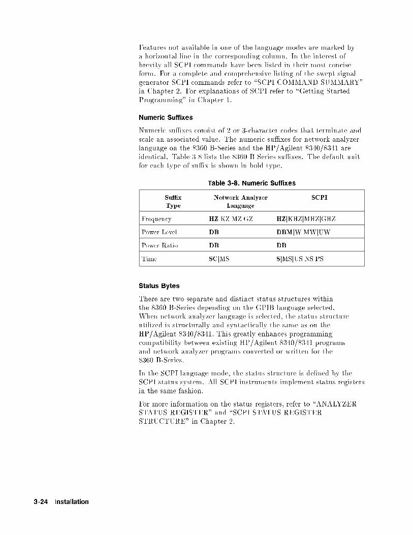
Features not available in one of the language modes are marked bya horizontal line in the corresponding column. In the interest ofbrevity all SCPI commands have been listed in their most conciseform. For a complete and comprehensive listing of the swept signalgenerator SCPI commands refer to \SCPI COMMAND SUMMARY"in Chapter 2. For explanations of SCPI refer to \Getting StartedProgramming" in Chapter 1.
Numeric Suffixes
Numeric su�xes consist of 2 or 3-character codes that terminate andscale an associated value. The numeric su�xes for network analyzerlanguage on the 8360 B-Series and the HP/Agilent 8340/8341 areidentical. Table 3-8 lists the 8360 B-Series su�xes. The default unitfor each type of su�x is shown in bold type.
Table 3-8. Numeric Suffixes
Su�xType
Network AnalyzerLanguage
SCPI
Frequency HZjKZjMZjGZ HZjKHZjMHZjGHZ
Power Level DB DBMjWjMWjUW
Power Ratio DB DB
Time SCjMS SjMSjUSjNSjPS
Status Bytes
There are two separate and distinct status structures withinthe 8360 B-Series depending on the GPIB language selected.When network analyzer language is selected, the status structureutilized is structurally and syntactically the same as on theHP/Agilent 8340/8341. This greatly enhances programmingcompatibility between existing HP/Agilent 8340/8341 programsand network analyzer programs converted or written for the8360 B-Series.
In the SCPI language mode, the status structure is de�ned by theSCPI status system. All SCPI instruments implement status registersin the same fashion.
For more information on the status registers, refer to \ANALYZERSTATUS REGISTER" and \SCPI STATUS REGISTERSTRUCTURE" in Chapter 2.
3-24 Installation

Table 3-9. Programming Language Comparison
Description Network Analyzer
Language
SCPI Language
ALC
Leveling mode, external A2 POW:ALC:SOUR DIOD;:POW:ATT:AUTO OFF
Leveling mode, internal A1 POW:ALC INT
Leveling mode, mm module SHA2 POW:ALC:SOUR MMH;:POW:ATT:AUTO OFF
Leveling mode, power meter A3 POW:ALC:SOUR PMET;:POW:ATT:AUTO OFF
Enable normal ALCoperation
A1jA2jA3jSHA2 POW:ALC:STAT ON
Disable ALC and controlmodulator drive directly
SHA3 POW:ALC:STAT OFF
Set output power, thendisable ALC
SHA1 POW:SEAR ON
Uncouple attenuator,control ALC independently
SHPS <num>DB POW:ATT:AUTO OFF;:POW <num>[DBM]
Frequency
Set CW frequency CW <num>freq su�x FREQ:CW <num>[freq su�x];MODE CW
Set start frequency FA <num>freq su�x FREQ:STAR <num>[freq su�x];MODE SWE
Set stop frequency FB <num>freq su�x FREQ:STOP <num>[freq su�x];MODE SWE
Set center frequency CF <num>freq su�x FREQ:CENT <num>[freq su�x];MODE SWE
Set frequency span DF <num>freq su�x FREQ:SPAN <num>[freq su�x];MODE SWE
Set swept mode step size SHCF <num>freq su�x FREQ:STEP <num>[freq su�x]
Set CW mode step size SHCW <num>freq su�x FREQ:STEP <num>[freq su�x]
Enable frequencyo�set function
SHFB <num>freq su�x FREQ:OFFS <num>[freq su�x];OFFS:STAT ON
Enable frequencymultiplier function
SHFA <num> FREQ:MULT <num>;MULT:STAT ON
Keep multiplication factor oninstrument on/o� or preset
SHAL (Refer to user de�ned preset)
Multiplication factor=1 oninstrument on/o� or preset
SHIP (Refer to user de�ned preset)
Zoom function SHST ||
Installation 3-25

Table 3-9. Programming Language Comparison (continued)
Description Network Analyzer
Language
SCPI Language
GPIB only functions
Output status byte OS *STB?(See SCPI common commands)
Status byte mask RM <num> *SRE(See SCPI common commands)
Extended status byte mask RE <num> *ESE(See SCPI common commands)
Clear status byte CS *CLS(See SCPI common commands)
Output learn string OL *LRN?(See SCPI common commands)
Mode string OM ||
Advance to next bandcross BC ||
Display updating DU DISP ONjOFF
Activate fast phaselock mode FP ||
Enable front panel knob EK SYST:KEY 132 (enable up)SYST:KEY 133 (enable down)
Increment frequency IF *TRG(See SCPI common commands)
Input learn string IL SYST:ILRN
Keyboard release KR ||
Select networkanalyzer mode
NA ||
Output active value OA (See SCPI Command Summary)
Output next bandcrossfrequency
OB DIAG:OUTP:BAND?
Output coupled parameters OC FREQ:STAR?;CENT?;:SWE:TIME?
Output diagnostics OD DIAG:OUTPj:FREQ?j:UNL?j:YOD?j:YTMD?
Output fault information OF DIAG:OUTP:FAUL?
Output identity OI *IDN?(See SCPI common commands)
Output last lock frequency OK DIAG:OUTP:FREQ?
Output interrogated value OP (See SCPI Command Summary)
Output power level OR POW:LEV?
3-26 Installation

Table 3-9. Programming Language Comparison (continued)
Description Network Analyzer
Language
SCPI Language
Set remote knob RB ||
Request status byte mask RE <num>,RM <num> *SRE <num>, *SRE?,*ESE <num>, *ESE?
Reset sweep RS ABOR
Number of steps ina stepped sweep
SN <num> SWE:POIN <num>
Swap network analyzerchannels
SW <1j0> ||
Test GPIB interface TI <num> DIAG:TINT? <num>
Sets sweep time lower limit TL <num>time su�x SWE:TIME:LLIM <num>[time su�x]
Take sweep TS TSW;*WAI
Instrument State
Instrument preset IP SYST:PRES
Local instrument control LOCAL 7XX LOCAL 7XX(XX=Source GPIB address)
Markers [n] is 1 to 5, 1 is default
Turn on and set marker Mn <num>freq su�x MARK[n]:FREQ<num>[freq su�x];STAT ON
Turn o� frequency marker MnM0 MARK[n] OFF
Enable M1-M2 sweep MP1 SWE:MARK:STAT ON
Disable M1-M2 sweep MP0 SWE:MARK:STAT OFF
Move start->M1 stop->M2 SHMP SWE:MARK:XFER
Enable delta marker MD1 MARK[n]:DELT? <num>,<num>
Disable delta marker MD0 MARK OFF
Move marker tocenter frequency
MC MARK[n]:FREQ?;:FREQ:CENT <response>[freq su�x]
Turn o� all markers SHMO MARK:AOFF
Turn on amplitude markers AK1 MARK[n]:AMPL ON;AMPL:VAL <num>[DB]
Turn o� amplitude markers AK0 MARK:AMPL OFF
Installation 3-27
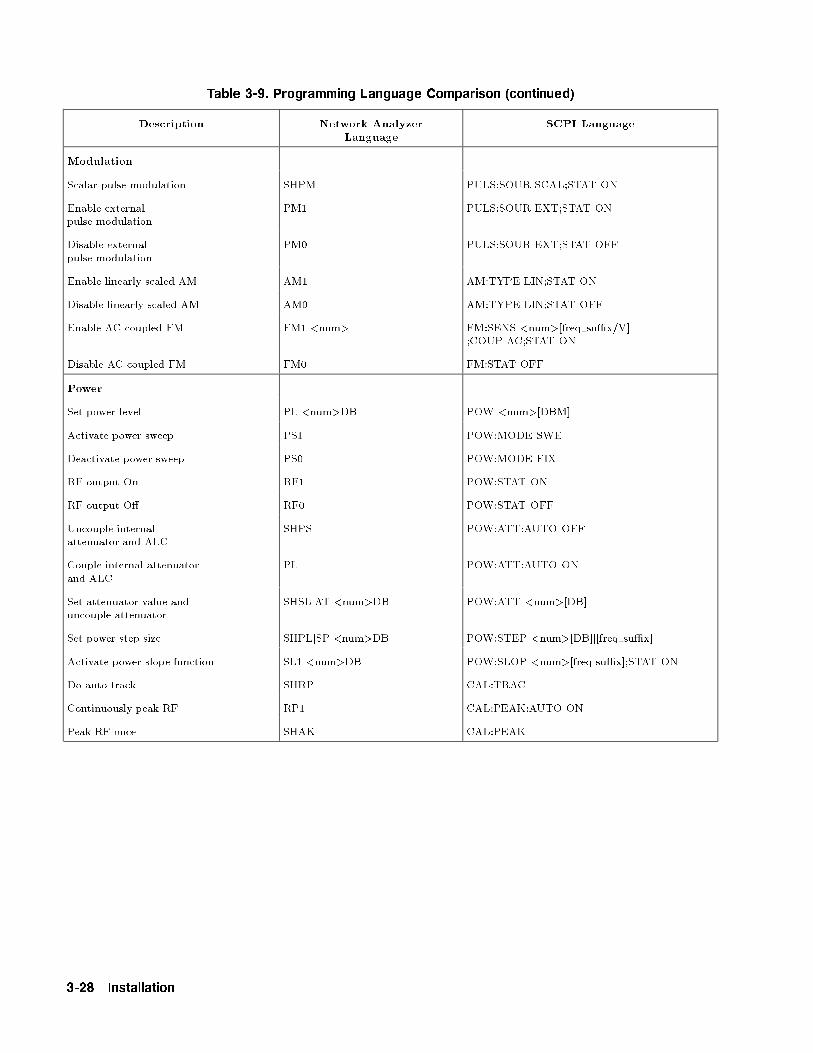
Table 3-9. Programming Language Comparison (continued)
Description Network Analyzer
Language
SCPI Language
Modulation
Scalar pulse modulation SHPM PULS:SOUR SCAL;STAT ON
Enable externalpulse modulation
PM1 PULS:SOUR EXT;STAT ON
Disable externalpulse modulation
PM0 PULS:SOUR EXT;STAT OFF
Enable linearly scaled AM AM1 AM:TYPE LIN;STAT ON
Disable linearly scaled AM AM0 AM:TYPE LIN;STAT OFF
Enable AC coupled FM FM1 <num> FM:SENS <num>[freq su�x/V];COUP AC;STAT ON
Disable AC coupled FM FM0 FM:STAT OFF
Power
Set power level PL <num>DB POW <num>[DBM]
Activate power sweep PS1 POW:MODE SWE
Deactivate power sweep PS0 POW:MODE FIX
RF output On RF1 POW:STAT ON
RF output O� RF0 POW:STAT OFF
Uncouple internalattenuator and ALC
SHPS POW:ATT:AUTO OFF
Couple internal attenuatorand ALC
PL POW:ATT:AUTO ON
Set attenuator value anduncouple attenuator
SHSLjAT <num>DB POW:ATT <num>[DB]
Set power step size SHPLjSP <num>DB POW:STEP <num>[DB]j[freq su�x]
Activate power slope function SL1 <num>DB POW:SLOP <num>[freq su�x];STAT ON
Do auto track SHRP CAL:TRAC
Continuously peak RF RP1 CAL:PEAK:AUTO ON
Peak RF once SHAK CAL:PEAK
3-28 Installation
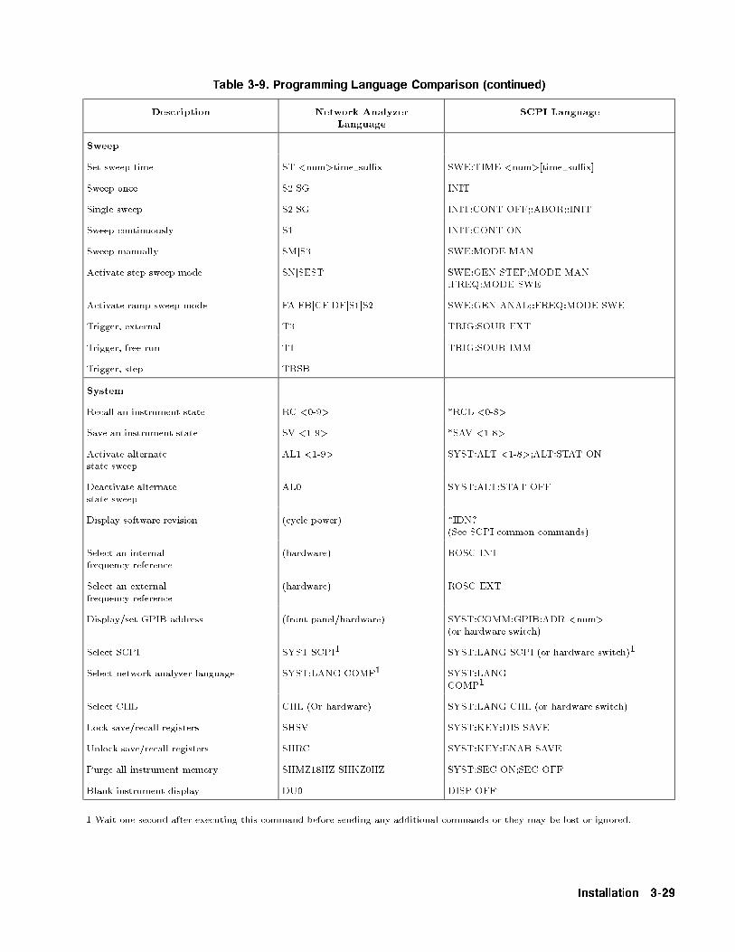
Table 3-9. Programming Language Comparison (continued)
Description Network Analyzer
Language
SCPI Language
Sweep
Set sweep time ST <num>time su�x SWE:TIME <num>[time su�x]
Sweep once S2jSG INIT
Single sweep S2jSG INIT:CONT OFF;:ABOR;:INIT
Sweep continuously S1 INIT:CONT ON
Sweep manually SMjS3 SWE:MODE MAN
Activate step sweep mode SNjSEST SWE:GEN STEP;MODE MAN:FREQ:MODE SWE
Activate ramp sweep mode FAjFBjCFjDFjS1jS2 SWE:GEN ANAL;:FREQ:MODE SWE
Trigger, external T3 TRIG:SOUR EXT
Trigger, free run T1 TRIG:SOUR IMM
Trigger, step TRSB ||
System
Recall an instrument state RC <0-9> *RCL <0-8>
Save an instrument state SV <1-9> *SAV <1-8>
Activate alternatestate sweep
AL1 <1-9> SYST:ALT <1-8>;ALT:STAT ON
Deactivate alternatestate sweep
AL0 SYST:ALT:STAT OFF
Display software revision (cycle power) *IDN?(See SCPI common commands)
Select an internalfrequency reference
(hardware) ROSC INT
Select an externalfrequency reference
(hardware) ROSC EXT
Display/set GPIB address (front panel/hardware) SYST:COMM:GPIB:ADR <num>(or hardware switch)
Select SCPI SYSTjSCPI1 SYST:LANG SCPI (or hardware switch)1
Select network analyzer language SYST:LANG COMP1 SYST:LANGCOMP1
Select CIIL CIIL (Or hardware) SYST:LANG CIIL (or hardware switch)
Lock save/recall registers SHSV SYST:KEY:DIS SAVE
Unlock save/recall registers SHRC SYST:KEY:ENAB SAVE
Purge all instrument memory SHMZ18HZ SHKZ0HZ SYST:SEC ON;SEC OFF
Blank instrument display DU0 DISP OFF
1 Wait one second after executing this command before sending any additional commands or they may be lost or ignored.
Installation 3-29

4
Operator's Check and Routine Maintenance
WARNING No operator serviceable parts inside. Refer servicing to qualified
personnel. To prevent electrical shock, do not remove covers.
Operator's Checks The local operator's check (front panel use) allows the operator tomake a quick check of the main swept signal generator functions priorto use.
For delete front panel options of the Agilent 8360 B-Series, use the\Front Panel Emulator Software" to perform an operator's check.
Service Information If the swept signal generator requires service and the routinemaintenance procedures do not clear the problem, contact a quali�edservice technician. A list of Agilent Technologies Sales and SupportO�ces is provided behind the \PREFACE" tab at the front of thismanual. To help the service technician identify the problem quickly,�ll out and attach a service repair tag. Service repair tags areprovided at the end of this chapter. If a self test error occurs, notethe name of the failure and the referenced paragraph number in thefailure symptoms/special control settings section of the tag. Provideany information that you feel is important to recreate the failure.
Operator's Check/Routine Maintenance 4-1
Local Operator'sCheck
Description The preliminary check provides assurance that most of the internalfunctions of the swept signal generator are working. The main checkprovides a general check of the overall functions of the swept signalgenerator. No external equipment is needed.
Preliminary Check Each time the swept signal generator is turned on the swept signalgenerator performs a series of self tests on the internal CPU, powersupplies, and front panel. When the self test is complete, the sweptsignal generator returns to the same functional con�guration thatit was in prior to power o�. When the �PRESET� key is engaged, theswept signal generator returns to the factory or user preset functionalcon�guration.
1. Turn the swept signal generator on. Note the functionalcon�guration.
2. Turn the swept signal generator o�. Verify that the amberSTANDBY LED is on.
3. Turn the swept signal generator on. Verify that the amberSTANDBY LED is o�, and that the green POWER ON LED ison.
a. Check the display, a cursor will appear in the upper-left cornerfollowed by the GPIB language, GPIB address, and the datecode of the �rmware installed in the swept signal generator.
b. The display will now indicate the functional con�gurationnoted in step 1.
c. Check the fan, it should be turning.
4-2 Operator's Check/Routine Maintenance
Main Check 1. Press �SERVICE�.
2. SelectNNNNNNNNNNNNNNNNNNNNNNNNNNNNNNNNNNNNNNNNNNNNNNNSelftest (Full) . Check that all tests performed pass.
3. Press �PRESET�. If the display indicates a user preset wasperformed, select
NNNNNNNNNNNNNNNNNNNNNNNNNNNNNNNNNNNNNNNNNNNNFactory Preset . Verify that the green
SWEEP LED is blinking, the amber RF ON/OFF LED is on, andthe red INSTR CHECK LED is o�.
4. Press �USER CAL�.
5. SelectNNNNNNNNNNNNNNNNNNNNNNNNNNNNNNNNNNNNNNNNNTracking Menu .
a. If the swept signal generator has Option 001, step attenuator,select
NNNNNNNNNNNNNNNNNNNNNNNNNNNNNNNNAuto Track . Wait for the swept signal generator to
�nish peaking before continuing.
b. If the swept signal generator has no step attenuator installed,provide a good source match on the output connector (a power
sensor or 10 dB attenuator will do). SelectNNNNNNNNNNNNNNNNNNNNNNNNNNNNNNNNAuto Track .
Wait for the swept signal generator to �nish peaking beforecontinuing.
6. Press �PRIOR�.
7. SelectNNNNNNNNNNNNNNNNNNNNNNNNNNNNNNNNNNNNNNNNNFreq Cal Menu .
8. SelectNNNNNNNNNNNNNNNNNNNNNNNNNNNNNNNNNNNNNNNNNNNNNNNNNNNNNSwp Span Cal Once . Verify that status problems do not
exist (UNLOCK, UNLVLED, or FAULT). An OVEN status messagewill appear on the message line if the swept signal generator hasbeen disconnected from ac power. This message will turn o�within 10 minutes, if it does not, there may be a problem. If aFAULT message is displayed, refer to menu map 6, Service, toaccess fault information.
9. Terminate the RF output with a good source match (eithera 50 load or power sensor). Press �POWER LEVEL�. Increasethe power level until the unleveled message is displayed on themessage line. Decrease the power level until the unleveled messageturns o�. Note the power level reading. Verify that the sweptsignal generator can produce maximum speci�ed power withoutbecoming unleveled.
This completes the operator's check. If the swept signal generatordoes not perform as expected, have a quali�ed service technicianisolate and repair the fault. See \Service Information."
Operator's Check/Routine Maintenance 4-3

RoutineMaintenance
Routine maintenance consists of replacing a defective line fuse,cleaning the air �lter, cleaning the cabinet, and cleaning the display.These items are discussed in the following paragraphs.
Table 4-1. Fuse Part Numbers
Voltage Fuse Part/Number
115 V 5A 250 V 2110-0010
230 V 3A 250 V 2110-0003
WARNING For continued protection against fire hazard replace line fuse only with
same type and rating. The use of other fuses or material is prohibited.
How to Replace theLine Fuse
The value for the line fuse is printed on the rear panel of the sweptsignal generator next to the fuse holder. See Figure 4-1
1. Turn o� the swept signal generator.
2. Remove the ac line cord.
Note The detachable power cord is the instrument disconnecting device.It disconnects the mains circuits from the mains supply before otherparts of the instrument. The front panel switch is only a standbyswitch and is not a LINE switch.
3. Using a small at-blade screwdriver, rotate the fuse capcounter-clockwise, and remove the fuse holder.
4. Replace the original fuse.
5. Replace the fuse holder in the rear panel. Using the screwdriver,rotate the fuse cap clockwise to secure the fuse holder in place.
6. Reconnect the swept signal generator to line power.
Figure 4-1. Replacing the Line Fuse
4-4 Operator's Check/Routine Maintenance

How to Clean the FanFilter
The cooling fan located on the rear panel has a thin foam �lter.How often the �lter must be cleaned depends on the environmentin which the swept signal generator operates. As the �lter collectsdust, the fan speed increases to maintain air ow (as the fan speedincreases, so does the fan noise). If the �lter continues to collectdust after the fan reaches maximum speed, air ow is reduced andthe swept signal generator's internal temperature increases. If theinternal temperature reaches 90 �C the swept signal generator willautomatically turn o� and the amber STANDBY LED will turn on.Clean the fan �lter as follows:
1. Turn o� the swept signal generator.
2. Remove the ac line cord.
Note The detachable power cord is the instrument disconnecting device.It disconnects the mains circuits from the mains supply before otherparts of the instrument. The front panel switch is only a standbyswitch and is not a LINE switch.
3. Remove the screws holding the fan cage. See Figure 4-2.
4. Remove the fan cage from the rear panel.
5. Rinse the fan cage, �lter, and the �lter retainer in warm water,then dry.
6. Reverse the removal procedure to reassemble the swept signalgenerator.
Figure 4-2. Removing the Fan Filter
Operator's Check/Routine Maintenance 4-5

How to Clean theCabinet
Warning To prevent electrical shock, disconnect the 8360 B-series swept signal
generator from the mains before cleaning.
Use a dry cloth or one slightly dampened with water to clean theexternal case parts. Do not attempt to clean internally.
How to Clean theDisplay Filter
The display of the swept signal generator is protected by a plasticdisplay �lter. To clean the display �lter, use mild soap or detergentand water, or a commercial window cleaner (ammonia does not hurtthe plastic surface). Use a soft, lint-free cloth. Do not use abrasivecleaners, tissues or paper towels, which can scratch the plastic.
4-6 Operator's Check/Routine Maintenance

5
Instrument History
This chapter is left blank until this manual requires changes.
Instrument History 5-1

Index
1 10 MHz frequency standard chosen automatically, T-110 MHz frequency standard external, T-110 MHz frequency standard internal, T-210 MHz frequency standard none chosen, T-210 MHz reference functions, R-110 MHz reference input connector, C-610 MHz reference output connector, C-61601 point atness array, C-12
2 2.4 mm connector, C-1127.778 kHz square wave, P-20
3 3.5 mm connector, C-11
8 8360 Adrs, E-18360 as controller, 3-7
A ABORtcommand de�ned, 1-118e�ect on trigger state, 1-111example using, 1-115
ABORt[abort]a�ect on trigger state, 1-110
abort statement, 1-57AC FM, F-12ac power switch, L-5active entry area, 1-4active entry area on/o�, E-5active entry arrow, 1-4adapters, 3-1GPIB, C-7
adapter, three-prong to two-prong, 3-4ADC fail, F-2addressswept signal generator, A-1, E-1
address changes, no front panel, 3-8address changes, prevent, 3-8address, changes to, 3-8addresses, factory-set interface, 3-7address menu, A-1address, printer, P-11address, programming power meter, M-8air ow, 3-9ALC bandwidth, M-16
Index-1

menu, A-11select auto, A-9select high, A-10select low, A-10
ALC bandwidth selection, 1-50ALC disabledtheory of, A-8
ALC levelinginternal, L-3mm-wave module, L-4normal, L-1power meter, L-4search, L-2
ALC menu, A-2{4ALC o�, L-1ALC o� mode, 1-32ALC open loop, L-1ALC search mode, 1-32align output �lter, A-27, P-1alternate registers, A-12altitude pressure, 3-9always calibrate sweep span, S-74AMALC o� mode, D-1deep, D-1, M-15depth, I-1exponentially scaled, A-15, A-18linearly scaled, A-15, A-19rate, I-1, M-15
AM bandwidth calibration, M-16AM/FM output connector, C-4AM input connector, C-4AM outputrear panel, M-11
amplitude markers, 1-14, A-17amplitude modulation, M-13display depth, M-9greater depth, D-1internal, I-1softkeys, A-14
amplitude modulation bandwidth calibration, A-12{14amplitude modulation on/o�, A-15{16, A-18{19AM waveformnoise, I-2ramp, I-2sine, I-3, I-6square, I-3triangle, I-4, I-7
analog sweep mode, S-73analyzer compatibility, P-13analyzer language, P-13analyzer programming language, A-19angle brackets, 1-64apply atness correction, F-10arrow keys, A-21
Index-2

assign softkey, A-22attenuator, uncouple, U-1attenuator uncouple, M-14attenuator, value set, S-59auto �ll increment, A-23auto �ll number of points, A-24auto �ll start, A-25auto �ll stop, A-26automatically set sweep time, S-76automatic sweep time, 1-10automatic trigger, stepped sweep, S-69auto track, A-27auto track failed message, 2a-1auxiliary interface connector, C-6auxiliary output connector, C-5
B bandwidthALC, A-9, A-10, A-11AM, A-12, A-13amplitude modulation, A-12, A-13
beginning frequency atness correction, A-25frequency list, A-25
bitsin general status register model, 1-106summary bit in general status register model, 1-107
blank display, B-1BNC connectors, C-4Boolean parametersdiscussed in detail, 1-85explained brie y, 1-75
brackets, angle, 1-64BUStrigger source de�ned, 1-119
C cabinet, clean, 4-5cablesGPIB, C-7
calco fail, F-3calibrate sweep span always, S-74calibrate sweep span once, S-75calibrationfull user, F-19sweep span, F-15
calibration failed message, 2a-2calibration, user functions, U-3calman fail, F-4calYO fail, F-4center frequency, 1-8, C-1CW coupled, C-13
center frequency marker, C-1CF/span sweep mode, zoom, Z-1change correction value, C-3change interface address, 3-8
Index-3
characterizationdiode detectors, 1-47
checks, operator, 4-1CIIL language, P-13clean cabinet, 4-5clean display, 4-6clean fan �lter, 4-5clear display, B-1clear fault, C-2clear memory, C-2clear point, C-3clear statement, 1-59*CLS, S-14colonexamples using, 1-69proper use of, 1-69, 1-85types of command where used, 1-67
command examples, 1-64commands, 1-80common, 1-67de�ned, 1-63event, 1-72implied, 1-72query, 1-72subsystem, 1-67syntax, 1-81
commands, common IEEE 488.2, S-14commands, SCPI programming, S-13command statements, fundamentals, 1-57command tableshow to read, 1-71how to use, 1-71
command treesde�ned, 1-68how to change paths, 1-68how to read, 1-68simpli�ed example, 1-71using e�ciently, 1-69
commasproblems with commas in input data, 1-65proper use of, 1-69, 1-82
common commands, 1-67, 1-69de�ned, 1-67
compare, analyzer language to SCPI, 3-24compensationnegative diode detectors, 1-47
condition register, 1-106connectionsto HP/Agilent 83550 series mm-wave modules, 3-22to HP/Agilent 8510 network analyzer, 3-21to HP/Agilent 8757C/E scalar analyzer, 3-21to HP/Agilent 8970B noise �gure meter, 3-22
connector10 MHz reference input, C-610 MHz reference output, C-6
Index-4
AM/FM output, C-4AM input, C-4auxiliary interface, C-6auxiliary output, C-5external ALC, C-5FM input, C-5GPIB, C-7pulse input, C-5pulse sync out, C-5pulse video out, C-5RF output, C-11source module interface, C-9stop sweep in/out, C-6sweep output, C-5trigger input, C-6trigger output, C-6volts/GHz, C-6Z-axis blank/markers, C-6
connectors, C-4{11connectors, mating, 3-8CONT, 1-12, C-11continuous leveling, L-1continuous sweep, 1-12, C-11continuous wave frequency, C-13control attenuator separately, U-1controllerde�ned, 1-63
controller, de�nition of, 1-56control power level, P-2conventions, typeface, viicooling air ow, 3-9copy frequency list, C-11copy list, C-11correcting for power sensitive devices, F-4correction valueenter, E-1
correction value entry, F-16COUNtin general programming model, 1-112
coupled attenuator, A-6coupled frequency, C-13coupled stepped sweep to sweep time, D-10coupling factor, C-12current pathde�ned, 1-68rules for setting, 1-68
custom menus, A-22CW/CF coupled, C-13CW frequency, C-13CW frequency, step size, U-2CW operation, 1-6
Index-5

D damage claims, 3-1data display area, 1-4data questionable event register, clear, S-14data typesexplained brie y, 1-73
date code of �rmware, S-60DC FM, F-13decrement key, A-21decrement step sizeCW frequency, U-2power, U-1
decrement step size, swept frequency, U-3deep AM, D-1, M-15defaulting language message, 2a-1de�ned preset, P-10de�ne increment size, A-23de�ne number of points, A-24de�ning sweep limits, 1-6, 1-8de�nitions of terms, 1-63delete, D-3delete active array entry, D-4delete all, D-3delete array, D-3delete current, D-4delete unde�ned entry, D-4delta marker, 1-14, D-5delta marker reference, D-6detectorcoupling factor, C-12
detector calibration, 1-47{48, E-6device enter statement, 1-61device output statement, 1-60diagnosticsfault information, F-1
diode detectorscharacterization of, 1-47
directional couplercoupling factor, C-12
disable interface address changes, 3-8disable save, S-1disable user atness array, C-12discrete parametersdiscussed in detail, 1-85explained brie y, 1-75
discrete response datadiscussed in detail, 1-86
display, 1-4display blank, B-1display, clean, 4-6display clear, B-1display status, D-6display status of phase-lock-loops, U-1display zero frequency, Z-1doubler amp mode auto, D-8doubler amp mode o�, D-9
Index-6

doubler amp mode on, D-9doubler amp softkeys, D-1down arrow, A-21dual source control, S-64dwell coupled, D-10dwell timefrequency point, E-3list array, all points, G-1stepped frequency mode, S-67
dwell time coupled, D-10
E EEROM fail, F-3EEROM failed, lost CAL message, 2a-2EEROM failed message, 2a-2enable register, 1-107in general status register model, 1-106
^END, 1-64^END[end], 1-81ending frequency atness correction, A-26frequency list, A-26
enter correction, E-1enter frequency value atness, E-2
enter list dwell, E-3enter list frequency, E-4enter list o�set, E-4enter statement, 1-61entry area, 1-4, E-5entry keys, E-5entry on LED, 1-5entry on/o�, E-5EOI, 1-64, 1-81EOL, suppression of, 1-61equipment supplied, 3-1erase active array entry, D-4erase array, D-3erase array entries, D-3erase memory, C-2erase unde�ned entry, D-4erase user de�ned menu, U-6erase user de�ned softkey, U-5error messages, 2-1, 2a-1{8error queue, clear, S-14*ESE, S-14*ESR?, S-14event commands, 1-72event detection trigger statedetails of operation, 1-112in general programming model, 1-110
event register, 1-107in general status register model, 1-106, 1-107
eventsevent commands, 1-72
Index-7

example program atness correction, 1-103GPIB check, 1-90local lockout, 1-91looping and synchronization, 1-99setting up a sweep, 1-93synchronous sweep, 1-101use of queries, 1-95use of save/recall, 1-97
example programs, 1-87{105examples, equipment used, 1-2examples, simple program messages, 1-72example, stimulus response program, 1-77extended numeric parametersdiscussed in detail, 1-84explained brie y, 1-74
extendersGPIB, C-9
EXTernaltrigger source de�ned, 1-119
external ALC BNC, L-3, L-4external ALC connector, C-5external AM, A-16external detector calibration, E-6external detector leveling, L-3external frequency standard, T-1external leveling, 1-23{29coupling factor, C-12detector calibration, E-6low output, 1-26theory of, A-7with detectors, couplers, or splitters, 1-23{26with power meters, 1-27with source modules, 1-28
external power meter range, P-23external pulse modulation, P-18external triggerfrequency list, L-9
external trigger, stepped sweep, S-70external trigger, sweep mode, S-63
F factor, coupling, C-12factory preset, P-10factory-set interface addresses, 3-7fan �lter, clean, 4-5fastest sweep-retrace cycle, S-62fault information, F-1fault information 1, F-2fault information 2, F-3fault menu, F-1fault statusclear, C-2
feature status, D-6�lter
Index-8
transition, 1-107�rmware datecode identify, S-60 atness arrayfrequency value, E-2user, F-4
atness corrected power, 1-33 atness correctionclear value, C-3copy frequency list, C-11frequency increment, A-23HP/Agilent 437B measure at all frequencies, M-7HP/Agilent 437B measure at one frequency, M-7, M-8HP/Agilent 437B measure functions, M-27number of points, A-24start frequency, A-25stop frequency, A-26
atness correction, example program, 1-103 atness menu, F-4 atness on/o�, F-10FMdeviation, I-4rate, I-5
FM coupling, M-17FM deviation, maximum, M-17FM input connector, C-5FM modulation, M-17FM on/o� AC, F-12FM on/o� DC, F-13FM on/o� ext, F-14FM on/o� int, F-14FM outputrear panel, M-11
FM waveformnoise, I-5ramp, I-6square, I-7
FNxfer fail, F-3forgiving listening, 1-66, 1-83frequencycenter, C-1coupled to center, C-13CW, C-13di�erence marker, D-5display zero, Z-1stepped sweep functions, S-68sweep mode de�ne start, S-61
frequency calibration menu, F-15frequency-correction pair, E-2frequency follow, F-16frequency increment, A-23frequency listdwell time, E-3dwell time, all points, G-1frequency increment, A-23frequency value, E-4
Index-9

number of points, A-24, E-4o�set value, all points, G-1power o�set, E-4start frequency, A-25step sweep activate, S-73stop frequency, A-26trigger external, L-9trigger functions, P-14trigger interface bus, L-8trigger point automatic, L-8
frequency list copy, C-11frequency list functions, L-5frequency list, number of points, L-6frequency markers, 1-14frequency menu, F-16frequency modulationAC, F-12coupling, F-10, F-11DC, F-13deviation, I-4display deviation, M-9internal, I-4rate, I-5softkeys, F-12
frequency multiplier, F-17frequency o�set, F-18frequency softkeys, F-16frequency span, S-60frequency standardchosen automatically, T-1external, T-1internal, T-2none chosen, T-2
frequency standard functions, R-1frequency start, S-61frequency start/stop=markers 1/2, S-62frequency stepstepped sweep activate, S-74
frequency, stepped mode dwell time, S-67frequency, stepped mode number of points, S-67frequency, stepped sweep step size, S-68frequency stop, S-71frequency sweep, 1-6manually, M-1marker1 to marker2, M-1
frequency sweep functions, S-72frequency sweep once, S-59frequency sweep, stop frequency, S-71frequency sweep, sweep time, S-75frequency valuedwell time, E-3 atness, E-2
front-panel checks, 4-2front panel connectors, C-4front panel error messages, 2a-1
Index-10
front panel operation, L-9full selftest, S-58full selftest command, S-17fullusr cal, F-19function locked out message, 2a-3fuse part numbers, 4-4fuse, replace, 4-4fuse selection, 3-3
G global dwelllist array, G-1
global o�setlist array, G-1
GPIBanalyzer language, P-13CIIL language, P-13printer address, P-11SCPI programming, P-14technical standard, 1-120trigger, frequency list, L-8
GPIB addresschanges to, 3-8factory-set, 3-7power meter, M-8swept signal generator, A-1, E-1
GPIB address identify, S-60GPIB address menu, A-1GPIB check, example program, 1-90GPIB connecting cables, 1-56GPIB connector, C-7GPIB connector mnemonics, C-9GPIB control functions, H-1GPIB, de�nition of, 1-55GPIB syntax error message, 2a-3GPIB triggerstepped sweep mode, S-70sweep mode, S-63
grounding pin, 3-4Group Execute Trigger, 1-119group execute trigger command, S-17
H HP/Agilent 437Bdetector calibration, E-6programming address, M-8
HP/Agilent 437B, atness correction measure all, M-7HP/Agilent 437B, measure correction, M-7, M-8HP/Agilent 437B measure correction functions, M-27HP/Agilent 8340status register, A-19
HP/Agilent 8340/41 system convert to 8360 system, 3-19HP/Agilent 83550-series interface connector, C-9HP/Agilent 83550 series system connections, 3-22HP/Agilent 8510 system connections, 3-21HP/Agilent 8516A interface connector, C-6
Index-11
HP/Agilent 8757C/E system connections, 3-21HP/Agilent 8970B system connections, 3-22humidity range, 3-9
I identify current datecode, S-60identifying string, S-14identify options command, S-14idle trigger state, 1-109details of operation, 1-111, 1-112in general programming model, 1-110
*IDN?, S-14IEEEmailing address, 1-120
IEEE 488.1how to get a copy, 1-120
IEEE 488.2how to get a copy, 1-120
IEEE 488.2 common commands, S-14IMMediateset by *RST, 1-112trigger command de�ned, 1-118trigger command discussed, 1-112trigger source de�ned, 1-119
implied commands, 1-72increment key, A-21increment step sizeCW frequency, U-2power, U-1
increment step size, swept frequency, U-3initial inspection, 3-1initialize the swept signal generator, P-8INITiateCONTinuous[initiatecont]:usage discussed, 1-111IMMediate[initiateimm]:usage discussed, 1-111
initiate trigger statedetails of operation, 1-111
INIT trigger con�gurationexample commands using, 1-115
instrumentsde�ned, 1-63
instrument state, A-12instrument state recall, R-1instrument state recall command, S-15instrument state restore string, S-14instrument state, save, S-1instrument state save command, S-17integer response datadiscussed in detail, 1-86
integersrounding, 1-84
interface addresschange, 3-8factory-set, 3-7power meter, M-8
Index-12
printer, P-11view, 3-8
interface bustrigger, frequency list, L-8
interface bus connector, C-7interface bus softkeys, H-1interface bus trigger, stepped sweep, S-70interface bus trigger, sweep mode, S-63interface languageanalyzer, P-13CIIL, P-13SCPI, P-14
interface language selection, 3-6internal AM, A-17internal AM depth, I-1internal AM rate, I-1internal FM rate, I-5internal frequency standard, T-2internal leveling, A-5internal leveling point, L-3internal pulse generator period, I-9internal pulse generator rate, I-9internal pulse generator width, I-10internal pulse mode auto, I-11internal pulse mode gate, I-11internal pulse mode trigger, I-11internal pulse modulation, P-19gate, I-11period, I-9rate, I-9softkeys, I-8trigger, I-11width, I-10
internal selftest, S-58internal timebase warmup time, 3-8invalid language message, 2a-3invalid save/recall register message, 2a-3invert input, I-12
K keyarrow, 1-5backspace, 1-5negative sign, 1-5numeric entry, 1-5terminator, 1-5
keysentry area, E-5
knob, R-2
Index-13

L language compatibility, 3-23language compatibility, analyzer to SCPI conversion, 3-23language identify, S-60language selection, 3-6left arrow, A-21LEVeltrigger command discussed, 1-112
leveling atness correction, F-10theory of, A-4{9
leveling accuracy, A-6leveling control, A-2leveling loopnormal, L-1
leveling modeALC o�, A-8, L-1normal, L-1search, A-8, L-2
leveling mode normal, A-5leveling modes, A-5leveling pointexternal detector, A-7, L-3internal, L-3module, L-4power meter, A-7, L-4source module, A-7
leveling points, A-5line fuse, replacement, 4-4line switch, L-5line voltage selection, 3-3listener, de�nition of, 1-56list frequencydwell time, E-3enter value, E-4number of points, E-4, L-6power o�set, E-4
list frequency functions, L-5list frequency step sweep activate, S-73list menu, L-5list modepoint trigger, external, L-9point trigger, interface bus, L-8trigger functions, P-14
list mode point triggerautomatic, L-8
local key, L-9local lockout, example program, 1-91local lockout statement, 1-58local statement, 1-58lock save, S-1looping and synchronization, example program, 1-99*LRN?, S-14
Index-14

M M1|M2 sweep, M-1maintenance, routine, 4-4making entries, 1-5manual part number, viimanual sweep, 1-12manual sweep key, M-1markercenter frequency, C-1delta, 1-14, D-5delta reference, D-6di�erence between, 1-14
marker 1 key, M-3marker 2 key, M-4marker 3 key, M-5marker 4 key, M-5marker 5 key, M-6marker functions, M-2marker key, M-2markersamplitude, 1-14, A-17frequency, 1-14
markers 1/2 set start/stop, S-62markers all o�, M-6marker sweep, M-1master, step control, S-64MATE compatibility, P-13mating connectors, 3-8maximize RF power, A-27measure correction all, M-7measure correction current, M-7measure correction unde�ned, M-8memory erase, C-2memory registers, 1-16memory registers 1 to 8, save, S-1menu maps, 2-1menus, previous, P-11message annunciators, 1-4message line, 1-4messagesdetails of program and response, 1-66simple examples, 1-72
messages, error, 2a-1{8message terminatorsresponse message terminator de�ned, 1-82
meter address, M-8meter measure functions, M-27meter on/o� AM, M-9meter on/o� FM, M-9mistrack, A-27mixers, 1-30mm-wave interface connector, C-9mm-wave interface mnemonics, C-10mm-wave module leveling, L-4mm-wave source modules system connections, 3-22mnemonics, 1-63, 1-64
Index-15

conventions for query commands, 1-63long form, 1-64short form, 1-64
modify HP/Agilent 8340/41 program for SCPI, 3-23MOD key, M-10modout on/o� AM, M-11modout on/o� FM, M-11modulationALC leveling, M-12AM, A-15, A-18amplitude, M-13AM rate, M-15deep AM, M-15dynamic range, M-14FM, M-17narrow pulses, M-21pulse, M-19pulse characteristics, P-16pulse, external, P-18pulse, internal, P-19pulse period, P-20pulse rate, P-21pulse, scalar, P-20reducing integrate{and{hold drift, M-16
module selection, M-23, M-24, M-25module selection softkeys, M-22monitor menu, M-26more key, M-27multi-pin connectors, C-6multiplication factorfrequency, F-17
N new linea�ect on current path, 1-68in response message terminator, 1-82symbol used for, 1-64use as a program message terminator, 1-64use as a response message terminator, 1-65with HP BASIC OUTPUT statements, 1-81
new line[new line]use as a program message terminator, 1-81
no frequency standard, T-2no front-panel, change interface address, 3-8noiseAM waveform, I-2FM waveform, I-5
noise �gure meter system connections, 3-22normal leveling mode, L-1number of points, A-24frequency list, A-24, E-4, L-6
number of step points, S-67numeric entry keys, E-5numeric parametersdiscussed in detail, 1-83
Index-16
explained brie y, 1-73
O ODELaytrigger command de�ned, 1-118
o�setlist array, all points, G-1
o�set frequency, F-18o�set, power, P-6on/o� switch, L-5*OPC, S-14*OPC?, S-14in example program, 1-79
*OPC?[opc], 1-111*OPC[opc], 1-111OPC pending ag, clear, S-14open leveling loop, L-1theory of, A-8
operating environment, 3-8operating temperature, 3-9operation complete command, S-14operation complete query, S-14Operation Pending Flag, 1-111operator checks, 4-1operator maintenance, 4-4*OPT?, S-14optimize tracking, A-27option 806, rack mount slides, 3-10option 908, rack ange kit, 3-13option 913, rack ange kit, 3-15optional parameters, 1-72option not installed message, 2a-4options available, 3-2options identify command, S-14output connector, C-11output statement, 1-60output status bytes, A-19OVEN message, 3-8OVERMOD messageduring frequency modulation, M-17
OVRMOD messageduring amplitude modulation, M-14
P parametersBoolean, 1-75, 1-85discrete, 1-75, 1-85extended numeric, 1-74, 1-84numeric, 1-73, 1-83optional, 1-72types explained brie y, 1-73
parserexplained brie y, 1-68
part number, fuses, 4-4part number, manual, viipeak fail, F-2
Index-17
peaking, 1-49peak RF always, P-1peak RF once, P-1periodic maintenance, 4-4period, pulse, P-20PLLwait fail, F-3PLLzero fail, F-3point clear, C-3points in stepped mode, S-67point trigger automaticlist mode, L-8
point trigger menu key, P-14powerleveling control, A-4
power cable, 3-4power correction value, E-1power level, 1-10power level functions, P-2power leveling, A-2internal point, L-3normal, L-1open loop, L-1search mode, L-2
power leveling with external detector, L-3power leveling with mm-wave module, L-4power leveling with power meter, L-4power level key, P-2power level step size, U-1power menu functions, P-5power menu key, P-5power meterHP/Agilent 437B, 1-34, 1-47
power meter leveling, L-4power meter measure correction functions, M-27power meter programming address, M-8power meter range, P-23power o�set, P-6list array, all points, G-1list frequency, E-4
power on/o�, RF, R-2power outputmaximizing, 1-49peaking, 1-49
power slope, 1-18, P-6power sweep, 1-18, P-7uncoupled operation, A-7
power sweep once, S-59power sweep, sweep time, S-75power switch, L-5precise talking, 1-66, 1-83pre�x number, viipreset conditions, HP/Agilent 8340/41 compared to 8360, 3-20preset key, 1-3, P-8preset modefactory, P-10
Index-18
user, P-10preset, save user de�ned, S-2pressure altitude, 3-9prevent interface address changes, 3-8previous menu, P-11printer address, P-11prior key, P-11program and response messages, 1-66program example atness correction, 1-103GPIB check, 1-90local lockout, 1-91looping and synchronization, 1-99queries and response data, 1-95save/recall, 1-97setting up a sweep, 1-93synchronous sweep, 1-101
program examples, 1-87{105programmable atness array, C-12program message examples, 1-72program messagesde�ned, 1-63
program message terminatorsa�ect on current path, 1-68de�ned, 1-81syntax diagram, 1-80use in examples, 1-64
programming languageanalyzer, P-13CIIL, P-13SCPI, P-14SCPI commands, S-13{26
programming language comparison, 3-24programming languagesde�nition of, H-1
programming language selection, 3-6pulse delay normal, P-15pulse delay softkeys, D-2pulse delay triggered, P-16pulse envelope, M-21optimizing, 1-49
pulse inputinvert, I-12
pulse input BNC, P-18, P-19, P-20pulse input connector, C-5pulse menu, P-16, P-17pulse modulation, M-19delay, P-15gate, I-11internal, I-8leveling, M-19narrow pulses, M-21period, I-9pulse envelope, M-21rate, I-9
Index-19
scalar network analyzer rise time, M-22softkeys, P-17source match, M-21trigger, I-11triggered delay, P-16video feedthrough, M-22width, I-10
pulse modulation softkeys, P-16pulse on/o� external, P-18pulse on/o� internal, P-19pulse on/o� scalar, P-20pulse period, P-20pulse rate, P-21pulse rise time internal generator, P-21{23pulse sync out connector, C-5pulse video out connector, C-5pulse width internal generator, P-23pwron fail, F-3
Q queriesde�ned, 1-63discussed, 1-66
queries, example program, 1-95query commands, 1-72query only, 1-72
query only, 1-72query status byte, S-17
R rack ange kit contents, 3-13rack ange kit installation, 3-14rack ange kit, no handles, 3-13rack ange kit, with handles, 3-15rack mount slide installation, 3-11rack mount slide kit contents, 3-10rampAM waveform, I-2FM waveform, I-6
ramp fail, F-2ramp sweep mode, S-73range, power meter, P-23*RCL, S-15rear panel connectors, C-4rear panel output softkeys, M-26recall instrument state command, S-15recall key, R-1recall registers, 1-16recall registers lost message, 2a-4recall/save, example program, 1-97reduce distortion, D-1reference oscillator functions, R-1registeraccessing of, 1-16
register, save, S-1related documents, 1-63
Index-20
remote statement, 1-57remove key from user de�ned menu, U-5repetition rate, pulse, P-21replace line fuse, 4-4reset swept signal generator command, S-15response datadiscrete, 1-86integer, 1-86
response data format, example program, 1-95response examples, 1-65response messagesde�ned, 1-63discussed in detail, 1-80syntax, 1-82
response message terminators, 1-65de�ned, 1-82
restore instrument state string, S-14reverse power e�ects, 1-30, 1-32RF on/o�, R-2RF output connector, C-11RF peaking, P-1RF powermaximize, A-27
RF power functions, P-5right arrow, A-21rise time automatic, pulse, P-21rise time fast, pulse, P-22rise time, pulse modulation and scalar analyzers, M-22rise time slow, pulse, P-22rootde�ned, 1-68
root commandsde�ned, 1-68
rotary knob, 1-5, R-2rounding, 1-84routine maintenance, 4-4RPG, R-2*RST, S-15
S *SAV, S-17save instrument state command, S-17save key, S-1save lock, S-1save/recall, example program, 1-97save register recall, R-1save registers, 1-16save user preset, S-2scalar network analyzer, pulse modulation rise time, M-22scalar network analyzer system connections, 3-21scalar pulse modulation, P-20SCPI conformance information, S-2SCPI error messages, 2a-5SCPI language, P-14search fail, F-4
Index-21

search leveling mode, L-2, M-21security functions, S-57selftest command, S-17selftest full, S-58selftest requires system interface o� message, 2a-4semicolonexamples using, 1-69problems with input statements, 1-65proper use of, 1-69
sequence operation trigger statedetails of operation, 1-114in general programming model, 1-110
serial number, viiservice information, 4-1service keys, 2-1service request enable register, S-17service tags>, 4-6set attenuator, S-59setting GPIB addresses, A-1shipment, 3-17shipping damage, 3-1sineAM waveform, I-3FM waveform, I-6
single, 1-12single frequency, C-13single sweep, 1-12, S-59slave, step control, S-65slope, power, P-6slow rise time, pulse modulation, M-22softkey label area, 1-4software revision, S-60SOURcein general programming model, 1-112trigger command de�ned, 1-119
source match, pulse modulation, M-21source module interface, L-4source module interface connector, C-9, M-23, M-24, M-25source module interface mnemonics, C-10source module leveling, L-4source module selection, M-22, M-23, M-24, M-25spaceproper use of, 1-69
span fail, F-2span, frequency, S-60span key, S-60span operation, 1-8S-parameter test set interface connector, C-6speci�cations, 2-1spectral purityenhancement of, 1-49
spectrum analyzers, 1-32squareAM waveform, I-3FM waveform, I-7
Index-22
square wave pulses, scalar, P-20*SRE, S-17SRQanalyzer language, A-19
standard event status enable register, S-14standard event status register, clear, S-14standard event status register, query value, S-14standard, frequency chosen automatically, T-1standard, frequency external, T-1standard, frequency internal, T-2standard, frequency none, T-2standard notation, 1-64standard operation status register, clear, S-14start frequency, S-61 atness correction, A-25frequency list, A-25
start=m1 stop=m2, S-62start/stop frequency, 1-6start sweep trigger, S-62start sweep trigger bus, S-63start sweep trigger external, S-63statusdisplay, D-6
status byte, clear, S-14status byte query, S-17status bytesanalyzer compatible, A-19
status bytes, compatible, 3-24status of phase-locked-loops, display, U-1status registeranalyzer, A-19
status registerscondition register, 1-106enable register, 1-107event register, 1-107example sequence, 1-107general model, 1-106transition �lter, 1-107
status register structure, SCPI, S-55status systemoverview, 1-106
*STB?, S-17step attenuator, A-6step control master, S-64step control slave, S-65step dwell, S-67stepped frequency mode, dwell time, S-67stepped mode, number of points, S-67stepped sweep coupled, D-10stepped sweep mode, S-74stepped sweep mode, step size, S-68step points, S-67step points dwell time, D-10step size, S-68step size, CW frequency, U-2
Index-23

step size, power level, U-1step size, swept frequency, U-3step sweep functions, S-68step sweep trigger automatic, S-69step sweep trigger bus, S-70step sweep trigger external, S-70stimulus response measurementsprogramming example, 1-77
stop frequency atness correction, A-26frequency list, A-26
stop frequency key, S-71stop sweep in/out connector, C-6storage, 3-17storage registers, 1-16store instrument state command, S-17store instrument state key, S-1string response datadiscussed in detail, 1-86
subsystem commands, 1-67de�ned, 1-67graphical tree format, 1-68tabular format, 1-71
summary bit, 1-107suppression of EOL, 1-61sweepcontinuous, C-11frequency, markers, M-1power, P-7
SWEepsimpli�ed subsystem command tree, 1-71
sweep complete, wait command, S-17sweep, example program, 1-93sweep functions, S-72sweep LED, 1-6, 1-12sweep modestepped functions, S-68
sweep mode ramp, S-73sweep modes, 1-12sweep mode step, S-74sweep mode stepped frequency list, S-73sweep once, S-59sweep output connector, C-5sweep span calibrate always, S-74sweep span calibrate once, S-75sweep span calibration, F-15sweep time, 1-10sweep time coupled to stepped sweep, D-10sweep time key, S-75sweep time set automatically, S-76swept o�set measurement, S-66swept operationcenter frequency, C-1
swept power, 1-18swept signal generator as controller, 3-7
Index-24
swept signal generator, no front-panel change address, 3-8swept signal generator remote address, A-1, E-1swept signal generator reset command, S-15swept signal generator status, D-6switch, line, L-5synchronization command, S-14synchronization, example program, 1-99synchronous sweep, example program, 1-101synchronous sweep operation, interface bus, S-17syntax diagramscommands, 1-81message terminators, 1-80program message, 1-80response message, 1-82
syntax drawings, 1-57system controller on bus message, 2a-4system interface connector, C-7system language (SCPI), P-14system menu keys, S-77
T tabproper use of, 1-69
talker, de�nition of, 1-56temperature, operating, 3-9terminatorsprogram message, 1-64, 1-81program message:use in examples, 1-64response message, 1-65
time, sweep set automatically, S-76tmr con ct fail, F-4track fail, F-2tracking, 1-49tracking functions, T-3transition �lter, 1-107in general status register model, 1-106
*TRG, S-17*TRG[trg], 1-119triangleAM waveform, I-4FM waveform, I-7
triggerautomatic, frequency list, L-8stepped sweep automatic, S-69stepped sweep external, S-70sweep mode external, S-63
trigger commandsde�ned, 1-118
trigger functionslist mode, P-14
trigger, group execute command, S-17TRIGGER (HP BASIC), 1-119trigger input BNC, S-71trigger input connector, C-6trigger, interface bus
Index-25
stepped sweep, S-70trigger out delay, T-4trigger output BNC, T-4trigger output connector, C-6trigger pointexternal, list mode, L-9interface bus, list mode, L-8
trigger statesevent detection, 1-112idle, 1-111in general programming model, 1-109sequence operation, 1-114
trigger systemgeneral programming model, 1-109INIT trigger con�guration, 1-115TRIG con�guration, 1-116
Trigger systemINIT con�guration, 1-115
TRIG trigger con�guration, 1-116*TST?, S-17two-tone control, S-64typeface conventions, vii
U uncoupled attenuator, A-7, U-1unleveled message, 1-10, 1-18unlock, information on status, U-1UNLVLD message, 1-18UNLVLED message, 1-10during amplitude modulation, M-14
up arrow, A-21user calibration functions, U-3user-de�ned leveling, F-4user de�ned menu, U-4user de�ned menu erase, U-6user de�ned softkey erase, U-5user de�ned softkeys, A-22user atness array, 1-33{46frequency value, E-2HP/Agilent 437B, 1-34power meter, 1-36
user atness correction, F-4HP/Agilent 437B measure, M-7, M-8power meter measure, M-27
user atness correction commands, example program, 1-103user preset, P-10user preset, save, S-2
Index-26
V vector network analyzer connections, 3-21V/GHz fail, F-2video feedthrough, pulse modulation, M-22view interface address, 3-8view previous menu, P-11volts/GHz connector, C-6
W *WAI, S-17wait for sweep complete command, S-17*WAI, use of example program, 1-101*WAI[wai], 1-111warmup time, 3-8waveformnoise, I-2, I-5ramp, I-2, I-6sine, I-3, I-6square, I-3, I-7triangle, I-4, I-7
waveform menu, W-1waveform softkeys, W-1whitespaceproper use of, 1-69
width, pulse, P-23without front-panel, change interface address, 3-8wrong password message, 2a-5
Z Z-axis blank/markers connector, C-6zero frequency, Z-1
zoom, Z-1
Index-27