graphic communication. the elevation and plan of an angled bearing block are shown. project an...
TRANSCRIPT

Graphic CommunicationGraphic Communication

The elevation and plan of an angled bearing block are shown.
Project an auxiliary elevation in the position indicated
Auxiliary Elevation Front Elevation
Plan
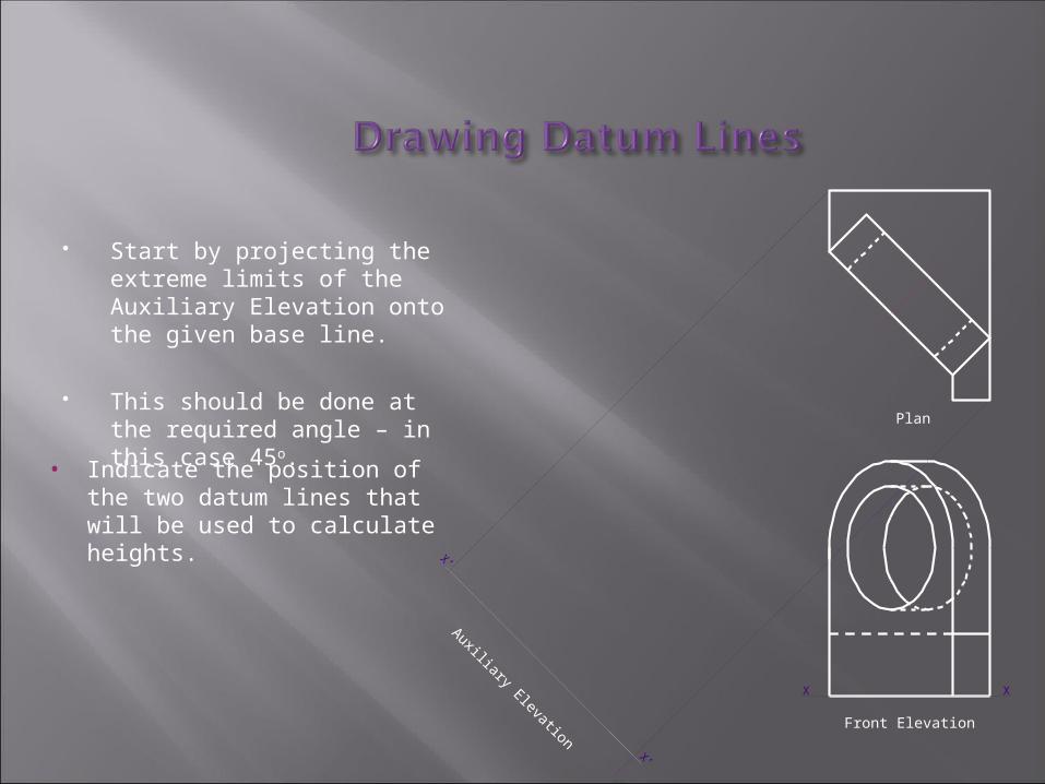
Start by projecting the extreme limits of the Auxiliary Elevation onto the given base line.
This should be done at the required angle – in this case 45o.
X X
X’
X’
Auxiliary Elevation Front Elevation
Plan
• Indicate the position of the two datum lines that will be used to calculate heights.

Measure the height of the base and the height to the centre line.
Transfer these dimensions to the Auxiliary Elevation.
X’
X’
Auxiliary Elevation Front Elevation
X X
Plan
• Draw suitable lines to indicate these positions.
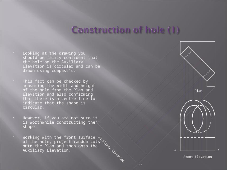
Looking at the drawing you should be fairly confident that the hole on the Auxiliary Elevation is circular and can be drawn using compass’s.
This fact can be checked by measuring the width and height of the hole from the Plan and Elevation and also confirming that there is a centre line to indicate that the shape is circular.
However, if you are not sure it is worthwhile constructing the shape.
Working with the front surface of the hole, project random cuts onto the Plan and then onto the Auxiliary Elevation.
X’
X’
Auxiliary Elevation
X X
Front Elevation
Plan

Measure the size from the datum line up to each of the points on the circle.
Transfer these dimensions onto the Auxiliary Elevation.
X
X’
X’
Auxiliary Elevation Front Elevation
X
Plan
• Draw a smooth curve through each of the points.

The same process can be carried out for the round top of the angled bearing block.
If you are confident that the top is a half circle then the shape can be drawn with compass’s using the existing centre lines.
However, if you are not sure, measure the heights for the curve using the existing random lines and transfer the heights onto the Auxiliary Elevation.
X’
X’
X X
Auxiliary Elevation Front Elevation
Plan
• Draw a smooth curve through each point.
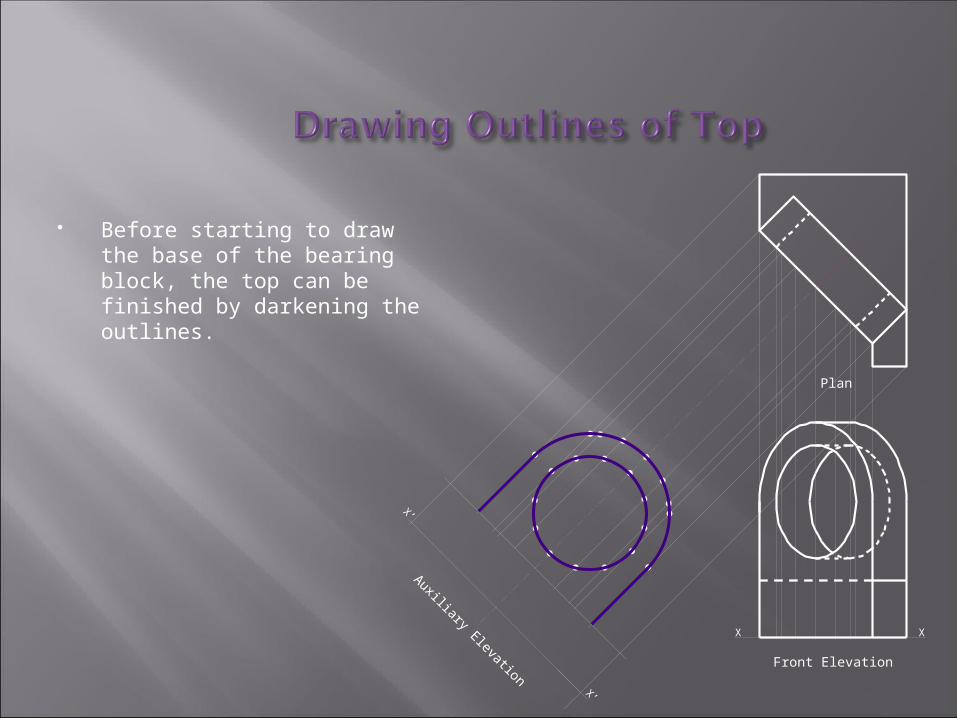
Before starting to draw the base of the bearing block, the top can be finished by darkening the outlines.
X’
X’
Auxiliary Elevation Front Elevation
X X
Plan

Project each of the corners of the base from the Plan to the Auxiliary Elevation.
Each of the edges can be darkened to finish the drawing.
X’
X’
Auxiliary Elevation
X X
Front Elevation
Plan
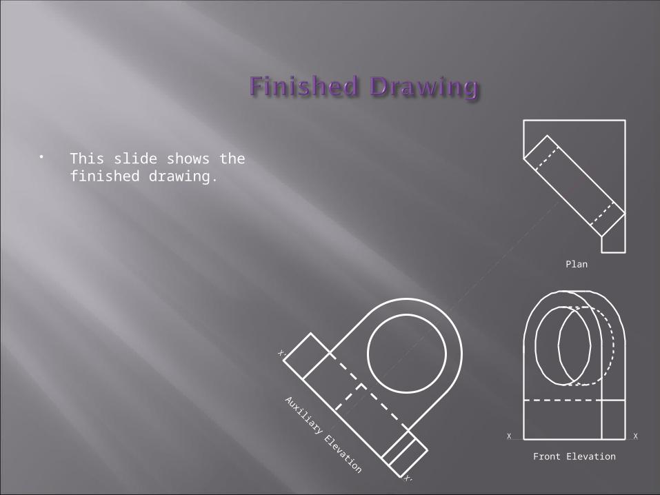
This slide shows the finished drawing.
X X
X’
X’
Auxiliary Elevation Front Elevation
Plan

Department Of Technical EducationDepartment Of Technical Education