grace construction products grace waterproofing systems · 2013-01-24 · waterproofing membrane...
TRANSCRIPT

GraceWaterproofing Systems
March 2012
Contractor’sHandbook
Grace Construction Products
Sticker prints in 2Colors - pms 368 green and pms 2738 blue
Product data • uPdates • tech letters • details • contact
www.graceconstruction.com

P
P
A
R O J E C T P O I N T E R S ..............................4
R O D U C T L I S T I N G .................................8
Product Descriptions, Usage, Coverages
Procor® .................................................................16Bituthene® ............................................................48Preprufe® ..............................................................80
T
AB
LE
O
F
CO
NT
EN
TS
P P L I C A T I O N I N S T R U C T I O N SA N D D E T A I L S ............................................ 16
A C C E S S O R I E S ..........................................150
T E C H N I C A L L E T T E R S ......................168

4
You and quality products are the key to a successful waterproofing project. Familiarize yourself with the various waterproofing membranes, accessory products and application techniques. These instructions and tips are intended to help you get the most out of a working day.
• Safety FirstWaterproofing products must be handled properly. Vapors from solvent-based primers and mastic are harmful and flammable. For these products, the best available information on safe handling, storage, personal protection, health and environmental considerations has been gathered. Material Safety Data Sheets (MSDS) are available at graceconstruction.com and users should acquaint themselves with this information. Carefully read detailed precaution statements on product labels and the MSDS before use. Check site conditions to ensure that all working areas are safe and free of hazardous conditions.
• Applications and LimitationsWaterproofing membrane systems may be used in various applications including:
– Foundation walls (free-standing or zero property line)
– Foundation walls and basement slab waterproofing (tanking)
– Blind side wall and slab – Plaza decks or balconies – Tunnels – Parking decks and bridge decks – Planters – Interior slabs including kitchens, laboratories
and mechanical rooms
5
P R O J E C T P O I N T E R S
There are several product limitations that the reader should know:
1. Waterproofing membranes should not be permanently exposed to sunlight.
2. Waterproofing membranes are not intended for roofing underlayment or through-wall flashing applications.
3. Waterproofing membranes should always be applied to properly prepared substrates; never directly to insulation or lightweight fills.
4. Waterproofing membranes should not be used as pond or tank liners except between concrete slabs.
5. Waterproofing membranes are not intended to provide the primary waterproofing for expansion joints.
6. Bituthene ® and Procor® are not intended for blind side or negative side applications.
7. Thin set mortar is not recommended for placement over Grace membranes unless approved by the mortar manufacturer.
8. Bituthene waterproofing membranes may be used over expanded polystyrene forming systems provided the criteria in the Bituthene Technical Letter “Insulated Wall Forming Systems” are observed.
9. Bituthene and Procor membranes should not be used in applications where in-service temperatures will exceed 130˚F (55˚C).
10. Preprufe® waterproofing membranes should not be used in applications where in-service temperatures will exceed 150˚F (65˚C).
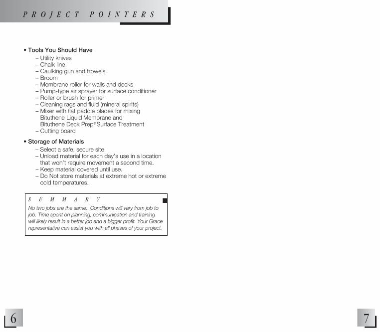
• Tools You Should Have – Utility knives – Chalk line – Caulking gun and trowels – Broom – Membrane roller for walls and decks – Pump-type air sprayer for surface conditioner – Roller or brush for primer – Cleaning rags and fluid (mineral spirits) – Mixer with flat paddle blades for mixing
Bituthene Liquid Membrane and Bituthene Deck Prep ®
Surface Treatment
– Cutting board
• Storage of Materials – Select a safe, secure site. – Unload material for each day’s use in a location
that won’t require movement a second time. – Keep material covered until use. – Do Not store materials at extreme hot or extreme
cold temperatures.
6 7
S U M M A R Y
No two jobs are the same. Conditions will vary from job to job. Time spent on planning, communication and training will likely result in a better job and a bigger profit. Your Grace representative can assist you with all phases of your project.
n
P R O J E C T P O I N T E R S
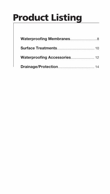
Product Listing
Waterproofing Membranes......................... 8
Surface Treatments................................... 10
Waterproofing Accessories...................... 12
Drainage/Protection.................................. 14

Description/Usage Coverage• Horizontal and vertical applications • 200 ft2 (18m2) /roll gross• Use at 25ºF (-4ºC) and above • Deduct up to 10% for• Use with water-based Bituthene overlaps and waste System 4000 Surface Conditioner • Horizontal and vertical applications • 200 ft2 (18m2) /roll gross• Use at 40ºF (5ºC) and above • Deduct up to 10% for • Use with Bituthene primers overlaps and waste• Horizontal and vertical applications • 200 ft2 (18m2) /roll gross• Use at 25º-60ºF (-4º to 16ºC) • Deduct up to 10% for• Use with Bituthene primers overlaps and waste • Horizontal sub-slab blind side applications • 392 ft2 (36 m2)/roll gross• Use above 25ºF (-4ºC) • Deduct up to 10% for• Use when concrete is cast directly overlaps and waste against membrane • Use with Preprufe Tape • Horizontal sub-slab blind side applications • 392 ft2 (36 m2)/roll gross• Use between 25ºF (-4ºC) and 60ºF (16ºC) • Deduct up to 10% for• Use when concrete is cast directly overlaps and waste against membrane• Use with Preprufe Tape• Vertical blind side applications • 460 ft2 (42 m2)/roll gross• Use above 25ºF (-4ºC) • Deduct up to 10% for • Use when concrete is cast directly overlaps and waste against membrane • Use with Preprufe Tape• Horizontal sub-slab blind side applications • 460 ft2 (42 m2)/roll gross• Use between 25ºF (-4ºC) and 60ºF (16ºC) • Deduct up to 10% for• Use when concrete is cast directly overlaps and waste against membrane• Use with Preprufe Tape• Horizontal and vertical blind side applications • 460 ft2 (42 m2)/roll gross• Intended for medium or intermittent water pressures • Deduct up to 10% for• Use above 25ºF (-4ºC) overlaps and waste• Use when concrete is cast directly against membrane• Pourable grade for horizontal applications • 132 ft2/kit at 60 mil (1.5 mm) • Two component, fluid applied thickness• Cures to fully-bonded elastomeric sheet • Coverage rates will be reduced over rough or uneven surfaces• Trowelable grade for vertical applications • 47 ft2/kit at 60 mil (1.5 mm) • Two component, fluid applied thickness• Cures to fully-bonded elastomeric sheet • Coverage rates will be reduced over rough or uneven surfaces• Spray grade for horizontal and vertical • 1875 ft2/kit at 60 mil applications (1.5 mm) thickness• Two component, fluid applied • Coverage rates will be reduced • Cures to fully-bonded elastomeric sheet over rough or uneven surfaces
98
n Waterproofing MembranesProducts
Bituthene® System 4000 Waterproofing Membrane (includes Surface Conditioner)3 ft x 66.7 ft (0.9m x 20m) roll
Bituthene® 3000 Waterproofing Membrane3 ft x 66.7 ft (0.9m x 20m) roll
Bituthene® Low Temperature Waterproofing Membrane 3 ft x 66.7 ft (0.9m x 20m) roll
Preprufe® 300R Waterproofing Membrane 4 ft x 98 ft (1.2m x 30.0 m) roll
Preprufe® 300LT Waterproofing Membrane4 ft x 98 ft (1.2 m x 30.0 m) roll
Preprufe® 160R Waterproofing Membrane 4 ft x 115 ft (1.2m x 35.0 m) roll
Preprufe® 160LT Waterproofing Membrane4 ft x 98 ft (1.2 m x 30.0 m) roll
Preprufe® 200 Waterproofing Membrane 460 ft2 (42 m2) roll
Procor® 10 Waterproofing Membrane 5.3 gallon kit
Procor® 20 Waterproofing Membrane 1.9 gallon kit
Procor® 75 Waterproofing Membrane 75 gallon kit
P R O D U C T L I S T I N G

n Surface Treatments
10 11
Bituthene® System 4000 Surface Conditioner0.6 gal (2.3 L) bottle
Bituthene® Primer WP-30005 gal (19 L) pail
Bituthene® Primer B2 LVC5 gal (19 L) pail
Bituthene® Deck Prep® Surface Treatment4 gal (15 L ) kit
Procor® Concrete Sealer5 gal (19 L) pail55 gal (209 L) drum
• Water-based conditioner for concrete, • 300 ft2/gal (7.5 m2/L) masonry and wood substrates• Use only with System 4000 membrane• Apply by spray or roller at 25ºF (-4ºC) and above• Dry one hour or until concrete returns to original color• Water-based latex primer • 500-600 ft2/gal (12-15 m2/L) • Use on all surfaces with Bituthene 3000 and Low Temperature • Use above 40ºF (5ºC) • Apply primer by roller, brush or sprayer • Dry 1 hour or until concrete returns to
original color• Solvent-based primer for concrete, • 325-425 ft2/gal (8-10.5 m2/L) masonry or wood substrates • Low VOC; <200 g/L• Use with Bituthene 4000, 3000 • Green and damp and Low Temperature concrete tolerant• Apply by roller or brush at 25ºF (-4ºC) and above• Dry one hour or until tack-free• Two-component, self-leveling, pourable • 25ft2/gal (0.6 m2/L) at grade asphalt modified urethane 0.06 in. (1.5 mm) thickness• Use as nonstructural repair material, • Coverage rates will be deck leveler, crack filler, primer, reduced over rough or temporary waterproofing material uneven surfaces• Use at 25º F (-4ºC) and above• Water-based conditioner for cast • 100-250 ft2/gal concrete and masonry substrates (2.5-6 m2/L)• Use with Procor membranes depending on surface • Apply by roller or airless sprayer roughness• Drying times vary
Description/Usage CoverageProducts
P R O D U C T L I S T I N G
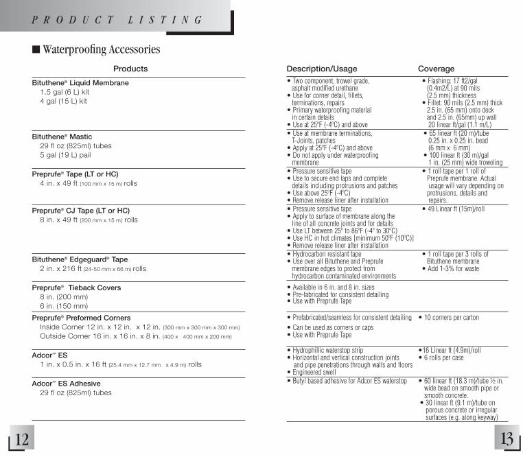
• Two component, trowel grade, • Flashing: 17 ft2/gal asphalt modified urethane (0.4m2/L) at 90 mils• Use for corner detail, fillets, (2.5 mm) thickness terminations, repairs • Fillet: 90 mils (2.5 mm) thick • Primary waterproofing material 2.5 in. (65 mm) onto deck in certain details and 2.5 in. (65mm) up wall• Use at 25ºF (-4ºC) and above 20 linear ft/gal (1.1 m/L)• Use at membrane terminations, • 65 linear ft (20 m)/tube T-Joints, patches 0.25 in. x 0.25 in. bead • Apply at 25ºF (-4ºC) and above (6 mm x 6 mm) • Do not apply under waterproofing • 100 linear ft (30 m)/gal membrane 1 in. (25 mm) wide troweling• Pressure sensitive tape • 1 roll tape per 1 roll of • Use to secure end laps and complete Preprufe membrane. Actual details including protrusions and patches usage will vary depending on • Use above 25ºF (-4ºC) protrusions, details and• Remove release liner after installation repairs.• Pressure sensitive tape • 49 Linear ft (15m)/roll • Apply to surface of membrane along the line of all concrete joints and for details• Use LT between 25º to 86ºF (-4º to 30ºC)• Use HC in hot climates [minimum 50ºF (10ºC)] • Remove release liner after installation • Hydrocarbon resistant tape • 1 roll tape per 3 rolls of • Use over all Bituthene and Preprufe Bituthene membrane membrane edges to protect from • Add 1-3% for waste hydrocarbon contaminated environments
• Available in 6 in. and 8 in. sizes • Pre-fabricated for consistent detailing • Use with Preprufe Tape
• Prefabricated/seamless for consistent detailing • 10 corners per carton• Can be used as corners or caps• Use with Preprufe Tape
• Hydrophillic waterstop strip •16 Linear ft (4.9m)/roll• Horizontal and vertical construction joints • 6 rolls per case and pipe penetrations through walls and floors• Engineered swell• Butyl based adhesive for Adcor ES waterstop • 60 linear ft (18.3 m)/tube ½ in.
wide bead on smooth pipe or smooth concrete.
• 30 linear ft (9.1 m)/tube on porous concrete or irregular surfaces (e.g. along keyway)
n Waterproofing Accessories
1312
Bituthene® Liquid Membrane1.5 gal (6 L) kit 4 gal (15 L) kit
Bituthene® Mastic29 fl oz (825ml) tubes 5 gal (19 L) pail
Preprufe® Tape (LT or HC)4 in. x 49 ft (100 mm x 15 m) rolls
Preprufe® CJ Tape (LT or HC)8 in. x 49 ft (200 mm x 15 m) rolls
Bituthene® Edgeguard® Tape2 in. x 216 ft (24-50 mm x 66 m) rolls
Preprufe® Tieback Covers8 in. (200 mm)6 in. (150 mm)
Preprufe® Preformed CornersInside Corner 12 in. x 12 in. x 12 in. (300 mm x 300 mm x 300 mm)
Outside Corner 16 in. x 16 in. x 8 in. (400 x 400 mm x 200 mm)
Adcor™ ES1 in. x 0.5 in. x 16 ft (25.4 mm x 12.7 mm x 4.9 m) rolls
Adcor™ ES Adhesive29 fl oz (825ml) tubes
Description/Usage CoverageProducts
P R O D U C T L I S T I N G

n Drainage/Protection
14 15
Hydroduct® 200 Drainage Composite4 ft x 50 ft (1.2 m x 15.3 m) roll
Hydroduct® 220 Drainage Composite4 ft x 50 ft (1.2 m x 15.3 m) roll
Hydroduct® 225 Drainage Composite4 ft x 50 ft (1.2 m x 15.3 m) roll
Hydroduct® 500RS Green Roof Composite4 ft x 50 ft (1.2 m x 15.3m) roll
Hydroduct® 550RS Green Roof Composite3 ft x 50 ft (0.91 m x 15.3 m)
Hydroduct® 660 Drainage Composite4 ft x 50 ft (1.2 m x 15.3 m) roll
Hydroduct® Coil 600 Perimeter Drain2 ft x 50 ft (0.6 m x 15.2 m) coil
Hydroduct® Tape1 in. x 200 ft (6 - 25 mm x 61 m) rolls
Hydroduct® Outlet Pipe Connector
Hydroduct® Connector Tee
Hydroduct® Corner Guard
• Vertical applications on • 200 ft2 (18.6m2)/roll non-waterproofed walls or with Preprufe® 160R or 200
• Vertical applications over • 200 ft2 (18.6m2)/roll waterproofing membranes • Adhere with Hydroduct Tape
• Heat and hydrocarbon resistant grade • 200 ft2 (18.6m2)/roll• Adhere with Hydroduct Tape
• Horizontal or vertical applications • 200 ft2 (18.6 m2)roll• Intergral root barrier • Adhere with Hydroduct Tape • Use over approved protection course • 7/16 in. (11 mm) thick
• Horizontal or vertical applications • 150 ft2 (13.9 m2)roll• Intergral root barrier • Adhere with Hydroduct Tape • Use over approved protection course • 1 in. (25 mm) thick
• All horizontal applications • 200 ft2 (18.6m2)/roll• Adhere with Hydroduct Tape
• Used in place of traditional perimeter • 50 linear ft (15.2 m)/run aggregate drain and pipe
• Self-adhesive, double-sided tape • 2-50 ft (15 m) strips/roll • Adheres Hydroduct Drainage of Hydroduct Drainage Composite and lightweight protection Composite boards to waterproofing membranes • 1 roll of tape per 2 rolls of Hydroduct Drainage Composite• Use with Hydroduct Coil 600 • 12/box • For end roll pipe connection
• Use with Hydroduct Coil 600 • 12/box • For lateral pipe connection
• Use with Hydroduct Coil 600 • 12/box • Provides continuous sheet while detailing corners
Description/Usage CoverageProducts
P R O D U C T L I S T I N G
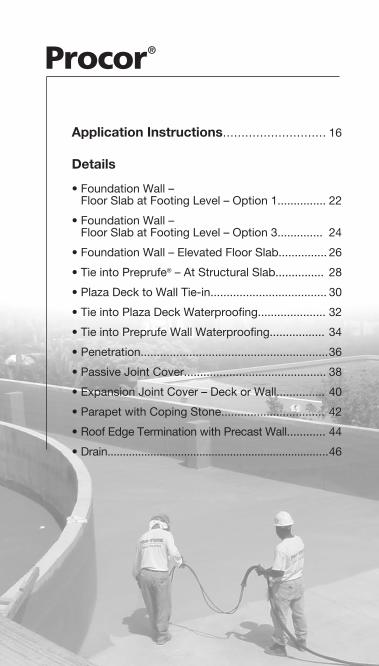
Procor®
Application Instructions............................ 16
Details • Foundation Wall –
Floor Slab at Footing Level – Option 1............... 22
• Foundation Wall – Floor Slab at Footing Level – Option 3.............. 24
• Foundation Wall – Elevated Floor Slab............... 26
• Tie into Preprufe® – At Structural Slab............... 28
• Plaza Deck to Wall Tie-in.................................... 30
• Tie into Plaza Deck Waterproofing..................... 32
• Tie into Preprufe Wall Waterproofing................. 34
• Penetration.......................................................... 36
• Passive Joint Cover............................................ 38
• Expansion Joint Cover – Deck or Wall............... 40
• Parapet with Coping Stone................................ 42
• Roof Edge Termination with Precast Wall............ 44
• Drain........................................................................ 46

17
4. Application Temperature Hand Application • Apply Procor 10 and Procor
20 membranes at ambient and substrate temperatures above 40°F (4°C).
• Do not apply the material if the ambient temperature is likely to fall below 32°F (0°C) within one hour of application completion.
Spray Application: • It is possible to work at tem-
peratures below 40°F (4°C) provided there is no frost or condensation on the substrate.
• The minimum temperature for spray application is 20°F (-7°C).
• Refer to Technical Bulletin, “Spraying Procor 75 at Low Temperatures,” on page 224 or contact your Grace Construction Products repre-sentative for details.
5. Mixing and Pot Life Hand Application• Open the Part A container and
stir or mix for a minimum of 15 seconds. Add the entire contents of the Part B contain-er to the Part A container.
• For mechanical mixing, use a slow speed (150 RPM), heavy duty drill with a spiral mixing paddle and mix for about 1 minute.
• For hand mixing, use a flat board or paddle and mix for about 2-3 minutes using a slow folding motion. (Photo 6)
• Do not overmix as overmixing will result in premature thick-ening of the material in the container and decrease the pot life.
• Once mixed, use immediately.
CAUTION: • Always install the entire
contents of the container as soon as possible. The reaction that occurs between Part A and Part B is exothermic (gives off heat) and mixed material left in the pail will reach temperatures higher than 212°F (100°C).
• For Procor 75, use qualified spray equipment systems. Mixing occurs within the spray gun assembly. Pre-mix Part A prior to pumping to bring any settled material back into solution.
6. Detailing (See Detail Section)
• Detailing should be completed prior to applying the full coverage of Procor membrane.
• The continuous field application should completely cover the detail areas to provide double thickness coverage.
(Photo 1) 1. Prepare Surface• Cementitious surfaces must be
wood float or form finish and free from frost, dirt, grease, oil or other contaminants.
• Surface irregularities and voids greater than 1⁄ 8 in. (3 mm) in depth should be pretreated with Procor membrane or with a concrete mix or grout.
• Remove windrows, form match lines and high spots greater than 3mm (1/8 in.) in height.
• Substrates must be wire brushed, swept with a stiff broom or blown off with low pressure air to remove dirt, dust and loose stones.
(Refer to Technical Letter on pg. 168)
• It may be necessary to apply Procor Concrete Sealer or a scratch coat of Procor to highly porous or rough substrates.
2. DecksThe deck is the structural base over which Procor® is applied. zAll decks shall be prepared to provide a clean, firm, smooth surface to accept application. Grace recommends the following:• No excessive deflection or
movement of the deck or other structural problems.
• Deck shall provide for support of maximum anticipated dead
and environmental loads, and for expansion and contraction suitable for the roof system structure.
• All projections, penetrations and openings in the deck should be completed before Procor application begins.
• Joints in pre-cast/pre-stressed concrete decks are to be grouted before membrane application so the top surface is level and smooth.
• A minimum slope to drain of 1/8 in./ft (11 mm/m) should be used on all concrete decks. This is best achieved with a monolithic structural slab and not with a separate concrete fill layer.
3. Application to “Green” Concrete or Damp Surfaces
• Procor may be applied to “green” concrete or over surfaces which are damp to the touch.
• It may be necessary to apply Procor Concrete Sealer or a scratch coat of Procor to “green” or damp substrates.
• Remove any visible water prior to application.
• Do not apply Procor water-proofing membranes in wet weather.
• Once applied, Procor will not be affected by light rain showers.
Procor® Waterproofing Membrane
A P P L I C A T I O N I N S T R U C T I O N S
16
For complete application instructions refer to the technical data sheet for Procor found at graceconstruction.com.

7. Hand Application on Horizontal Surfaces
• Pour the mixed Procor 10 directly from the container and spread using a steel trowel, flexible spreader, float or screed. A metal squeegee with thickness guides at the ends is accept-able and flexible bladed rubber squeegees may also be used. (Photo 2)
• A notched squeegee is not recommended since it will leave thin spots in the waterproofing.
• The membrane can typically accept foot traffic after 24 to 48 hours.
• When a minimum slope of 1/8 in./ft (11 mm/m) cannot be achieved, 2 coats of Procor membrane should be applied to achieve total thickness of 120 mils.
8. Hand Application on Vertical Surfaces
• Scoop the Procor 20 directly from the pail or apply using a steel trowel. (Photo 3)
• Spread the material uniformly across the surface with only one or two passes, starting at the bottom of the wall and pull-ing the material up the wall.
• Additional passes with the trowel over the material will cause the material to become stringy and difficult to trowel.
9. Spray Application• Procor 75 may be spray
applied to horizontal and vertical surfaces. (Photo 4)
• Contact Grace Construction Products for appropriate spray equipment.
10. Thickness Control• Thickness is controlled in
both horizontal and vertical applications by marking the area and spot checking the thickness with a wet film thickness gauge. (Photo 5)
• Swipe and trowel marks on the Procor membrane are acceptable as long as the minimum thickness is maintained.18 19
(Photo 3) Procor 20
(Photo 4) Procor 75
(Photo 2) Procor 10
• It is also possible that exces-sive exotherming (heat build-up) could occur on the substrate if Procor is applied too thickly in a single application.
• Areas of sponginess due to exotherming should be repaired by cutting away the affected area and re-applying correct thickness membrane. (Repair according to Section 11)
• Do not cover the material after it is mixed.
• Do not add water to thin the product.
11. Visual Work Inspection• Review all work.• Damaged Procor should be
repaired by cutting away the affected area to solid, fully-adhered membrane. The exposed area should then be patched with Procor to give a minimum overlap of 6 in. (150 mm) onto the existing Procor.
• Where the area surrounding the damaged Procor is con-taminated with dirt or is more than seven days old, it should be pressure washed or lightly abraded with a wire brush, course sanding disc or similar method to ensure good adhesion.
12. Drainage, Protection or Insulation
• Protect Procor membranes to avoid damage from other trades, construction materials and backfill. (Photo 7)
• Protection products may be installed on the same day as the Procor membrane.
• Bonding of the protection products to the Procor membrane is achieved if the protection products are installed when the Procor membrane is tacky, generally 1-2 hours after the Procor membrane is installed.
(Photo 5)
(Photo 6)
(Photo 7)
A P P L I C A T I O N I N S T R U C T I O N S
• To achieve non-bonded pro-tection, wait until the surface is no longer tacky, or spread cement dust or lime to remove the tack prior to applying the protection.
• Take care not to displace the Procor membrane.
• On horizontal applications, use Hydroduct 660 Drainage Composite. Alternate methods of protection are 2 layers of 1⁄8 in. (3 mm) or 1 layer of 1⁄4 in. (6 mm) asphalt hardboard, 1 in. extruded polystyrene insulation boards may also be used and are compatible with Procor membranes provided a slip sheet is used between the Procor and the polystyrene.
• On vertical applications, use Hydroduct 220 Drainage Composite. An alternate method of protection is 1 in. (25 mm) polystyrene. Such an alternative does not provide positive drainage to the system.
13. Backfill and Flood Tests• Allow Procor waterproofing
membrane to cure at least 24 hours prior to backfill to avoid displacement of the membrane.
• Use care during the backfill operation to avoid damage to the waterproofing system.
• Backfill should be added and compacted in 6 in. (150 mm) to 12 in. (300 mm) lifts to avoid stresses on the water-proofing system.
• Settlement stresses may
compromise the integrity of the waterproofing system.
• Before flood testing, be sure the structure will withstand the dead load of the water. Start flood test 48 hours after completing the application of Procor fluid applied water-proofing.
• Flood test all horizontal applications with a maximum 2 in. (50 mm) head of water for 24 hours. Mark any leaks and repair when the membrane is dry.
• When a flood test is not fea-sible, use of electric field vector mapping (EFVM) is acceptable.
14. Cleaning• Tools and equipment are most
effectively cleaned by allowing the material to cure and removing it the next day.
• Procor Flushing Oil is available to clean spray equipment.
15. Storage and Handling Information
• Procor waterproofing membranes containers should be stored under cover in original sealed containers above 40°F (4°C) and below 100°F (38°C).
• Keep Part B from freezing during storage. The shelf life is 9 months in unopened containers.
20 21
16. Limitations• Procor membranes should not
be used in areas where they will be permanently exposed to sunlight, weather or traffic.
• Procor membranes should not be used in negative side or blind side waterproofing applications.
• Protect Procor membranes as soon as possible to avoid damage from other trades, construction materials or backfiill.
A P P L I C A T I O N I N S T R U C T I O N S
22 23
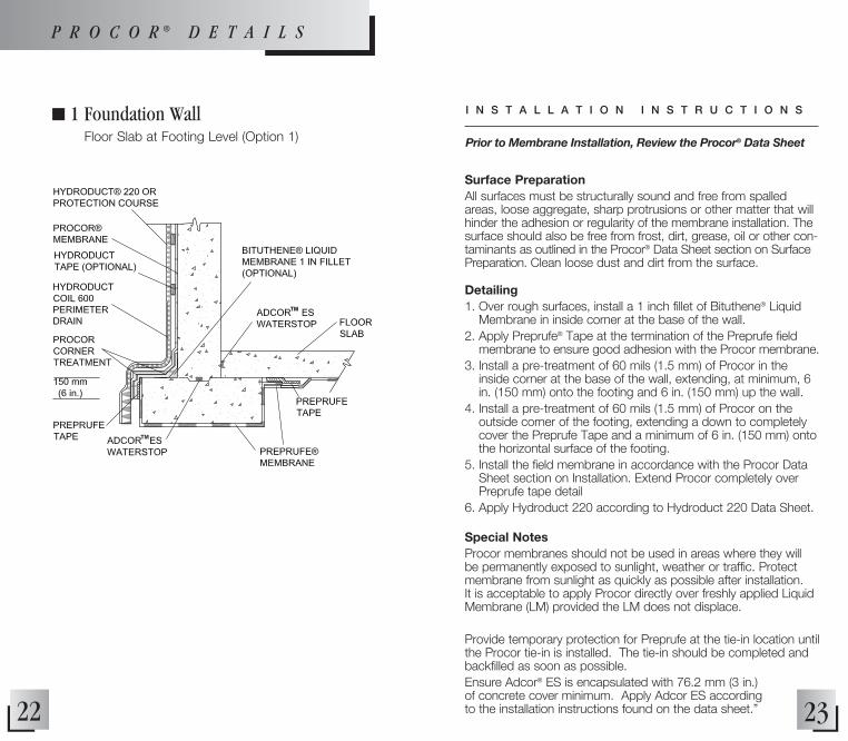
n 1 Foundation Wall Floor Slab at Footing Level (Option 1)
P R O C O R ® D E T A I L S
Surface PreparationAll surfaces must be structurally sound and free from spalled areas, loose aggregate, sharp protrusions or other matter that will hinder the adhesion or regularity of the membrane installation. The surface should also be free from frost, dirt, grease, oil or other con-taminants as outlined in the Procor® Data Sheet section on Surface Preparation. Clean loose dust and dirt from the surface.
Detailing1. Over rough surfaces, install a 1 inch fillet of Bituthene® Liquid
Membrane in inside corner at the base of the wall.2. Apply Preprufe® Tape at the termination of the Preprufe field
membrane to ensure good adhesion with the Procor membrane. 3. Install a pre-treatment of 60 mils (1.5 mm) of Procor in the
inside corner at the base of the wall, extending, at minimum, 6 in. (150 mm) onto the footing and 6 in. (150 mm) up the wall.
4. Install a pre-treatment of 60 mils (1.5 mm) of Procor on the outside corner of the footing, extending a down to completely cover the Preprufe Tape and a minimum of 6 in. (150 mm) onto the horizontal surface of the footing.
5. Install the field membrane in accordance with the Procor Data Sheet section on Installation. Extend Procor completely over Preprufe tape detail
6. Apply Hydroduct 220 according to Hydroduct 220 Data Sheet.
Special NotesProcor membranes should not be used in areas where they will be permanently exposed to sunlight, weather or traffic. Protect membrane from sunlight as quickly as possible after installation. It is acceptable to apply Procor directly over freshly applied Liquid Membrane (LM) provided the LM does not displace.
Provide temporary protection for Preprufe at the tie-in location until the Procor tie-in is installed. The tie-in should be completed and backfilled as soon as possible.Ensure Adcor® ES is encapsulated with 76.2 mm (3 in.) of concrete cover minimum. Apply Adcor ES according to the installation instructions found on the data sheet.”
Prior to Membrane Installation, Review the Procor® Data Sheet
I N S T A L L A T I O N I N S T R U C T I O N S

24 25
n 3 Foundation Wall Floor Slab at Footing Level (Option 3)
NOTE: THE FOOTIING KEYWAY SHOULD BE FORMED TO CREATE AREGULAR AND UNIFORM SHAPE ALLOWING PROPER DETAILING OF THE
BITUTHENE LIQUID MEMBRANE.
Surface PreparationAll surfaces must be structurally sound and free from spalled areas, loose aggregate, sharp protrusions or other matter that will hinder the adhesion or regularity of the membrane installation. The surface should also be free from frost, dirt, grease, oil or other contaminants as outlined in the Procor® Data Sheet section on Surface Preparation. Clean loose dust and dirt from the surface.
Detailing1. Apply 90 mil (2.3 mm) thick Bituthene® Liquid Membrane on
horizontal surface of footing in keyway. Extend Liquid Membrane a minimum of 2.5 in. (65 mm) onto horizontal sur-face of footing on each side of foundation wall, and up external foundation wall surface a minimum of 2.5 in. (65 mm).
2. Install a pre-treatment of 60 mils (1.5 mm) of Procor in the inside corner at the base of the wall, extending, at minimum, 3 in. (75 mm) onto the footing and 3 in. (75 mm) up the wall.
3. Install the field membrane in accordance with the Procor Data Sheet section on Installation
4. Extend Procor field membrane over corner treatment and onto the horizontal surface of the footing.
5. Apply Hydroduct 220 according to Hydroduct 220 Data Sheet. Hydroduct may be adhered directly to freshly applied Procor by simply placing the Hydroduct in the Procor.
6. Apply a strip of Bituthene membrane onto the Liquid Membrane that extends beyond the internal foundation wall surface.
7. Install Preprufe® in accordance with the Preprufe data sheet. Overlap Preprufe onto the Bituthene Strip a minimum of 3 in. (75 mm).
8. Install Preprufe CJ Tape centered over the edge of the Preprufe and adhere to the Bituthene Strip and Preprufe.
9. Apply a termination seal of Bituthene Liquid Membrane along Preprufe CJ Tape and Bituthene Strip termination.
Special NotesProcor membranes should not be used in areas where they will be permanently exposed to sunlight, weather or traffic. Protect membrane from sunlight as quickly as possible after installation. It is acceptable to apply Procor directly over freshly applied Bituthene Liquid Membrane (LM) provided the LM does not displace.Ensure Adcor™ ES is encapsulated with 76.2 mm (3 in.) of concrete cover minimum. Apply Adcor ES according to the installation instructions found on the data sheet.
Prior to Membrane Installation, Review the Procor® Data Sheet
I N S T A L L A T I O N I N S T R U C T I O N SP R O C O R ® D E T A I L S

26 27
n 5 Foundation Wall Elevated Floor Slab
Surface PreparationAll surfaces must be structurally sound and free from spalled areas, loose aggregate, sharp protrusions or other matter that will hinder the adhesion or regularity of the membrane installation. The surface should also be free from frost, dirt, grease, oil or other con-taminants as outlined in the Procor® Data Sheet section on Surface Preparation. Clean loose dust and dirt from the surface.
Detailing1. Install the Procor and Preprufe membranes in accordance with
the Procor and Preprufe Data Sheet section on installation.2. Apply Hydroduct 220 according to Hydroduct 220 Data Sheet.
Hydroduct may be adhered directly to freshly sprayed Procor by simply placing the Hydroduct in the wet Procor.
3. Terminate the Preprufe at the foundation wall. 4. Apply Preprufe Wall Termination detail PRE039.
Special NotesProcor membranes should not be used in areas where they will be permanently exposed to sunlight, weather or traffic. Protect membrane from sunlight as quickly as possible after installation.Ensure Adcor™ ES is encapsulated with 76.2 mm (3 in.) of con-crete cover minimum. Apply Adcor ES according to the installa-tion instructions found on the data sheet.
Prior to Membrane Installation, Review the Procor® Data Sheet
I N S T A L L A T I O N I N S T R U C T I O N S
*NOTE: NOT INTENDED FOR HYDROSTATIC CONDITIONS
P R O C O R ® D E T A I L S
28 29
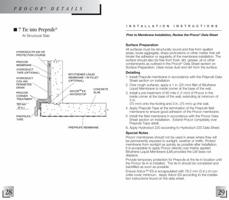
n 7 Tie into Preprufe® At Structural Slab
Surface PreparationAll surfaces must be structurally sound and free from spalled areas, loose aggregate, sharp protrusions or other matter that will hinder the adhesion or regularity of the membrane installation. The surface should also be free from frost, dirt, grease, oil or other contaminants as outlined in the Procor® Data Sheet section on Surface Preparation. Clean loose dust and dirt from the surface.
Detailing1. Install Preprufe membrane in accordance with the Preprufe Data
Sheet section on installation.2. Over rough surfaces, apply a 1 in. (25 mm) fillet of Bituthene
Liquid Membrane to inside corner at the base of the wall.3. Install a pre-treatment of 60 mils (1.5 mm) of Procor in the
inside corner at the base of the wall, extending at minimum of 3 in. (75 mm) onto the footing and 3 in. (75 mm) up the wall.
4. Apply Preprufe Tape at the termination of the Preprufe field membrane to ensure good adhesion of the Procor membrane.
5. Install the field membrane in accordance with the Procor Data Sheet section on Installation. Extend Procor completely over Preprufe Tape detail.
6. Apply Hydroduct 220 according to Hydroduct 220 Data Sheet.
Special NotesProcor membranes should not be used in areas where they will be permanently exposed to sunlight, weather or traffic. Protect membrane from sunlight as quickly as possible after installation. It is acceptable to apply Procor directly over freshly applied Bituthene Liquid Membrane (LM) provided the LM does not displace.Provide temporary protection for Preprufe at the tie-in location until the Procor tie-in is installed. The tie-in should be completed and backfilled as soon as possible.Ensure Adcor™ ES is encapsulated with 76.2 mm (3 in.) of con-crete cover minimum. Apply Adcor ES according to the installa-tion instructions found on the data sheet.
Prior to Membrane Installation, Review the Procor® Data Sheet
I N S T A L L A T I O N I N S T R U C T I O N S
P R O C O R ® D E T A I L S

30 31
n 11 Plaza Deck to Wall Tie-in
Surface PreparationAll surfaces must be structurally sound and free from spalled areas, loose aggregate, sharp protrusions or other matter that will hinder the adhesion or regularity of the membrane installation. The surface should also be free from frost, dirt, grease, oil or other contaminants as outlined in the Procor® Data Sheet section on Surface Preparation. Clean loose dust and dirt from the surface.
Detailing1. Install a pre-treatment of 60 mils (1.5 mm) of Procor on the
outside corner at the top of the wall, extending, at minimum, 3 in. (75 mm) onto the wall and onto the deck.
2. Install a pre-treatment of 60 mils (1.5 mm) of Procor to the concrete cold joint between the wall and deck. Note this is a non-movement joint. Extend the pre-treatment a minimum of 3 in. (75 mm) to each side of the joint.
3. Install the field membrane in accordance with the Procor Data Sheet section on Installation
4. Apply Hydroduct 220 on the wall and Hydroduct 660 on the deck according to the respective Hydroduct Data Sheets. Hydroduct may be adhered directly to freshly sprayed Procor by simply placing the Hydroduct in the Procor.
Special NotesProcor membranes should not be used in areas where they will be permanently exposed to sunlight, weather or traffic. Protect membrane from sunlight as quickly as possible after installation.Ensure Adcor™ ES is encapsulated with 76.2 mm (3 in.) of con-crete cover minimum. Apply Adcor ES according to the installa-tion instructions found on the data sheet.
Prior to Membrane Installation, Review the Procor® Data Sheet
I N S T A L L A T I O N I N S T R U C T I O N S
P R O C O R ® D E T A I L S

32 33
n 13 Tie into Plaza Deck Waterproofing
Surface PreparationAll surfaces must be structurally sound and free from spalled areas, loose aggregate, sharp protrusions or other matter that will hinder the adhesion or regularity of the membrane installation. The surface should also be free from frost, dirt, grease, oil or other contaminants as outlined in the Procor® Data Sheet section on Surface Preparation. Clean loose dust and dirt from the surface.
Detailing1. Install Preprufe Membrane onto the vertical soil retention system
up to the level of the horizontal deck.2. Pour concrete and remove the top 12 in. (300 mm) of tempo-
rary soil retention to gain access to the wall.3. Install a strip of Preprufe Tape onto the Preprufe Membrane, a
minimum of 2 in. (50 mm) from the top of the wall.4. Install a pre-treatment of 60 mils (1.5 mm) of Procor on the
outside corner, extending down a minimum of 6 inches onto the vertical surface, completely covering the Preprufe Tape.
5. Install a pre-treatment of 60 mils (1.5 mm) of Procor to the concrete cold joint. Note this is a non-movement joint. Extend the pre-treatment a minimum of 3 in. (75 mm) to each side of the joint.
6. Install the field membrane in accordance with the Procor Data Sheet section on Installation
7. Apply Hydroduct 220 to the wall and Hydroduct 660 to the deck according to the respective Data Sheets. Hydroduct may be adhered directly to freshly sprayed Procor by simply placing the Hydroduct in the Procor.
Special NotesProcor membranes should not be used in areas where they will be permanently exposed to sunlight, weather or traffic. Protect membrane from sunlight as quickly as possible after installation.Provide temporary protection for Preprufe at the tie-in location until the Procor tie-in is installed. The tie-in should be completed and backfilled as soon as possible.”Ensure Adcor™ ES is encapsulated with 76.2 mm (3 in.) of con-crete cover minimum. Apply Adcor ES according to the installa-tion instructions found on the data sheet.
Prior to Membrane Installation, Review the Procor® Data Sheet
I N S T A L L A T I O N I N S T R U C T I O N S
P R O C O R ® D E T A I L S
*NOTE: HYDRODUCT ON DECK AND TIE-IN TO WALL NOT SHOWN FOR CLARITY.

34 35
n 15 Tie into Preprufe® Wall Waterproofing Plan View
Surface PreparationAll surfaces must be structurally sound and free from spalled areas, loose aggregate, sharp protrusions or other matter that will hinder the adhesion or regularity of the membrane installation. The surface should also be free from frost, dirt, grease, oil or other contaminants as outlined in the Procor® Data Sheet section on Surface Preparation. Clean loose dust and dirt from the surface.
Detailing1. Install Preprufe over the prepared vertical surface following the
standard vertical application instructions.2. Extend the Preprufe Membrane a minimum of 6 in. (150 mm)
beyond the end of the blind-side wall and terminate in formwork to allow for tie-in.
3. Once the wall is poured and cured, remove the formwork.4. Apply Preprufe Tape at the termination of the Preprufe
field membrane to ensure good adhesion with the Procor Membrane.
5. Install the field membrane in accordance with the Procor Data Sheet section on Installation. Extend Procor completely over Preprufe Tape detail.
Special NotesProcor membranes should not be used in areas where they will be permanently exposed to sunlight, weather or traffic. Protect membrane from sunlight as quickly as possible after installation.Provide temporary protection for Preprufe at the tie-in location until the Procor tie-in is installed. The tie-in should be completed and backfilled as soon as possible.
Prior to Membrane Installation, Review the Procor® Data Sheet
I N S T A L L A T I O N I N S T R U C T I O N S
P R O C O R ® D E T A I L S
*NOTE: HYDRODUCT OR APPROvED PROTECTION COURSE NOT SHOWN FOR CLARITY OvER PROCOR.

36 37
n 21 Penetration
Surface PreparationAll surfaces must be structurally sound and free from spalled areas, loose aggregate, sharp protrusions or other matter that will hinder the adhesion or regularity of the membrane installation. The surface should also be free from frost, dirt, grease, oil or other contaminants as outlined in the Procor® Data Sheet section on Surface Preparation. Clean loose dust and dirt from the surface.
Detailing1. Grout penetration solid to prevent movement may compromise
waterproofing integrity.2. Apply a 1 in. (25 mm) fillet of Bituthene Liquid Membrane to
inside corner at the base of the penetration*.3. Apply Preprufe tape to the penetration to ensure good adhesion
between the pipe and the Procor Membrane.4. Install a pre-treatment of 60 mils (1.5 mm) of Procor to the
inside corner where the penetration meets the deck, extending at minimum of 3 in. (75 mm) onto the deck and completely over the Preprufe tape detail.
5. Install the field membrane in accordance with the Procor Data Sheet section on Installation. Extend Procor completely over Preprufe tape detail.
6. Apply Hydroduct 220 according to Hydroduct 220 Data Sheet.
Special NotesProcor membranes should not be used in areas where they will be permanently exposed to sunlight, weather or traffic. Protect membrane from sunlight as quickly as possible after installation. It is acceptable to apply Procor directly over freshly applied Bituthene Liquid Membrane (LM) provided the LM does not displace.*Procor 10 or Procor 20 can also be used as a 1 in. (25 mm) fillet in step 2.
Prior to Membrane Installation, Review the Procor® Data Sheet
I N S T A L L A T I O N I N S T R U C T I O N S
P R O C O R ® D E T A I L S
*NOTE: HYDRODUCT OR APPROvED PROTECTION COURSE NOT SHOWN FOR CLARITY.
38 39
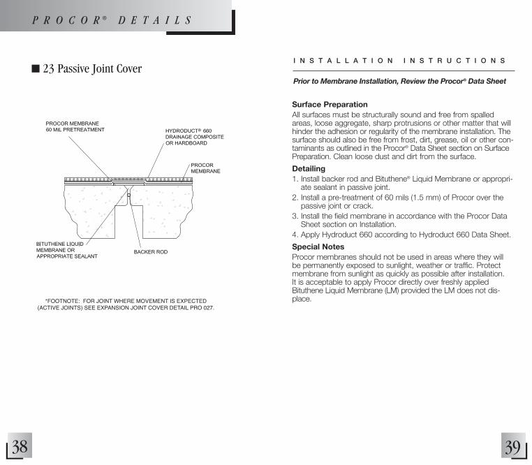
n 23 Passive Joint Cover
*FOOTNOTE: FOR JOINT WHERE MOvEMENT IS EXPECTED (ACTIvE JOINTS) SEE EXPANSION JOINT COvER DETAIL PRO 027.
Surface PreparationAll surfaces must be structurally sound and free from spalled areas, loose aggregate, sharp protrusions or other matter that will hinder the adhesion or regularity of the membrane installation. The surface should also be free from frost, dirt, grease, oil or other con-taminants as outlined in the Procor® Data Sheet section on Surface Preparation. Clean loose dust and dirt from the surface.
Detailing1. Install backer rod and Bituthene® Liquid Membrane or appropri-
ate sealant in passive joint.2. Install a pre-treatment of 60 mils (1.5 mm) of Procor over the
passive joint or crack.3. Install the field membrane in accordance with the Procor Data
Sheet section on Installation. 4. Apply Hydroduct 660 according to Hydroduct 660 Data Sheet.
Special NotesProcor membranes should not be used in areas where they will be permanently exposed to sunlight, weather or traffic. Protect membrane from sunlight as quickly as possible after installation. It is acceptable to apply Procor directly over freshly applied Bituthene Liquid Membrane (LM) provided the LM does not dis-place.
Prior to Membrane Installation, Review the Procor® Data Sheet
I N S T A L L A T I O N I N S T R U C T I O N S
P R O C O R ® D E T A I L S
40 41
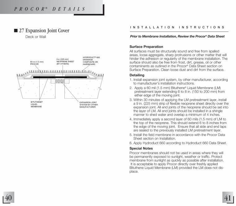
n 27 Expansion Joint Cover Deck or Wall
mil
Surface PreparationAll surfaces must be structurally sound and free from spalled areas, loose aggregate, sharp protrusions or other matter that will hinder the adhesion or regularity of the membrane installation. The surface should also be free from frost, dirt, grease, oil or other contaminants as outlined in the Procor® Data Sheet section on Surface Preparation. Clean loose dust and dirt from the surface.
Detailing1. Install expansion joint system, by other manufacturer, according
to manufacturer’s installation instructions.2. Apply a 60 mil (1.5 mm) Bituthene® Liquid Membrane (LM)
pretreatment layer extending 6 to 8 in. (150 to 200 mm) from either edge of the moving joint.
3. Within 30 minutes of applying the LM pretreatment layer, install a 9 in. (225 mm) strip of flexible neoprene sheet directly over the expansion joint. All end joints of the neoprene should be set into the layer of LM. All end joints should be installed in a shingle manner to shed water and overlap a minimum of 4 inches.
4. Immediately apply a second layer of 60 mils (1.5 mm) of LM to the top of the neoprene. This should extend 6 to 8 inches from the edge of the moving joint. Ensure that all side and end laps are sealed to the previously installed LM pretreatment layer.
5. Install the field membrane in accordance with the Procor Data Sheet section on Installation.
6. Apply Hydroduct 660 according to Hydroduct 660 Data Sheet.
Special NotesProcor membranes should not be used in areas where they will be permanently exposed to sunlight, weather or traffic. Protect membrane from sunlight as quickly as possible after installation. It is acceptable to apply Procor directly over freshly applied Bituthene Liquid Membrane (LM) provided the LM does not dis-place.
Prior to Membrane Installation, Review the Procor® Data Sheet
I N S T A L L A T I O N I N S T R U C T I O N S
P R O C O R ® D E T A I L S

42 43
n 28 Parapet with Coping Stone
Surface PreparationAll surfaces must be structurally sound and free from spalled areas, loose aggregate, sharp protrusions or other matter that will hinder the adhesion or regularity of the membrane installation. The surface should also be free from frost, dirt, grease, oil or other con-taminants as outlined in the Procor® Data Sheet section on Surface Preparation. Clean loose dust and dirt from the surface.
Detailing1. Apply pre-treatment of Procor membrane in corner, extending
a minimum of 6 in. (150 mm) onto wall and 6 in. (150 mm) onto deck.
2. Install the field membrane in accordance with the Procor Data Sheet section on Installation.
3. After Procor membrane has cured, install metal flashing (by others) as shown under the coping stone and mechanically attach on the outside of the parapet wall.
4. Ensure flashing is of adequate length to completely cover the exposed Procor membrane
5. Cover flashing with the use of a metal coping system (by others) as shown.
6. Apply Hydroduct 660 according to Hydroduct 660 Data Sheet.
Special NotesProcor membranes should not be used in areas where they will be permanently exposed to sunlight, weather or traffic. Protect membrane from sunlight as quickly as possible after installation.
Prior to Membrane Installation, Review the Procor® Data Sheet
I N S T A L L A T I O N I N S T R U C T I O N S
NOTE: 1 INCH FILLET OF BITUTHENE® LIQUID MEMBRANE IN THE CORNER IS OPTIONAL.
HYDRODUCT OR APPROvED PROTECTION COURSE NOT SHOWN FOR CLARITY.
P R O C O R ® D E T A I L S
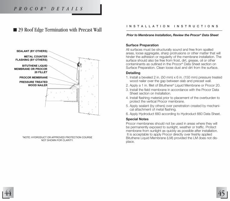
n 29 Roof Edge Termination with Precast Wall
44 45
Surface PreparationAll surfaces must be structurally sound and free from spalled areas, loose aggregate, sharp protrusions or other matter that will hinder the adhesion or regularity of the membrane installation. The surface should also be free from frost, dirt, grease, oil or other contaminants as outlined in the Procor® Data Sheet section on Surface Preparation. Clean loose dust and dirt from the surface.
Detailing1. Install a beveled 2 in. (50 mm) x 6 in. (150 mm) pressure treated
wood nailer over the gap between slab and precast wall.2. Apply a 1 in. fillet of Bituthene® Liquid Membrane or Procor 20. 3. Install the field membrane in accordance with the Procor Data
Sheet section on Installation. 4. Install flashing material prior to placement of the overburden to
protect the vertical Procor membrane. 5. Apply sealant (by others) over penetration created by mechani-
cal attachment of metal flashing.6. Apply Hydroduct 660 according to Hydroduct 660 Data Sheet.
Special NotesProcor membranes should not be used in areas where they will be permanently exposed to sunlight, weather or traffic. Protect membrane from sunlight as quickly as possible after installation. It is acceptable to apply Procor directly over freshly applied Bituthene Liquid Membrane (LM) provided the LM does not dis-place.
Prior to Membrane Installation, Review the Procor® Data Sheet
I N S T A L L A T I O N I N S T R U C T I O N S
P R O C O R ® D E T A I L S
*NOTE: HYDRODUCT OR APPROvED PROTECTION COURSE NOT SHOWN FOR CLARITY.
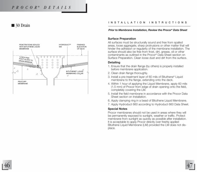
n 30 Drain
46 47
Surface PreparationAll surfaces must be structurally sound and free from spalled areas, loose aggregate, sharp protrusions or other matter that will hinder the adhesion or regularity of the membrane installation. The surface should also be free from frost, dirt, grease, oil or other contaminants as outlined in the Procor® Data Sheet section on Surface Preparation. Clean loose dust and dirt from the surface.
Detailing1. Ensure that the drain flange (by others) is properly installed
before membrane application.2. Clean drain flange thoroughly.3. Install a pre-treatment layer of 60 mils of Bituthene® Liquid
membrane to the flange, extending onto the deck. 4. Within 1 hour of applying the Liquid Membrane, apply 60 mils
(1.5 mm) of Procor from edge of drain opening onto the field, completely covering the LM.
5. Install the field membrane in accordance with the Procor Data Sheet section on Installation.
6. Apply clamping ring in a bead of Bituthene Liquid Membrane.7. Apply Hydroduct 660 according to Hydroduct 660 Data Sheet.
Special NotesProcor membranes should not be used in areas where they will be permanently exposed to sunlight, weather or traffic. Protect membrane from sunlight as quickly as possible after installation. It is acceptable to apply Procor directly over freshly applied Bituthene Liquid Membrane (LM) provided the LM does not dis-place.
Prior to Membrane Installation, Review the Procor® Data Sheet
I N S T A L L A T I O N I N S T R U C T I O N S
P R O C O R ® D E T A I L S

Bituthene®
Application Instructions............................ 48
Details • Foundation Wall –
Floor Slab at Footing Level – Option 2.............. 52
• Foundation Wall – Floor Slab at Footing Level – Option 4.............. 54
• Foundation Wall – Elevated Floor Slab – Option 2.......................... 56
• Foundation Wall – Structural Slab...................... 58
• Plaza Deck to Wall Tie-in.................................... 60
• Tie into Plaza Deck Waterproofing..................... 62
• Penetration......................................................... 64
• Pools, Fountains, Steps..................................... 66
• Plaza Deck – Deck to Wall Inside Corner – Option 1............... 68
• Plaza Deck – Deck to Wall Inside Corner – Option 2............... 70
• Passive Joint Cover............................................ 72
• Expansion Joint Cover – Deck or Wall.................. 74
• Expansion Joint Cover – Deck to Wall Junction............................................ 76
• Drain....................................................................78

• Only apply to recommended substrates, not to membrane.
3. Pretreat All Details (Refer to Details Section)
Vertical Corners• Apply 12 in. (300 mm)
membrane strip centered on corner.
• Cover all pretreated corners with full sheet of membrane to ensure 2-ply coverage.
Control Joints, Construction Joints, Cracks, Expansion Joints• Install appropriate expansion
joint assembly (as needed) to provide primary waterproofing seal. (Refer to pages 84 and 86)
• Cover joint assembly with Bituthene membrane as shown in Details.
Drains• Apply coller of Bituthene
Membrane or LM, centered over drain; extend 6 in. (150 mm) onto deck.
• Apply full sheet of membrane over collar; cut membrane flush to inside wall of drain.
• Install clamping ring in cured bed of Bituthene Mastic or Bituthene Liquid Membrane.
(Refer to Details Section)
4. Horizontal Application• All horizontal surfaces should
be sloped to drain at least 1/8 in./ft (11 mm/m).
• Apply from low point to high point.
• Roll out 6-8 ft (2-2.5 m). Align on printed guideline of previous sheet or chalk line.
• When a minimum slope of 1/8 in./ft (11 mm/m), cannot be achieved, 2 layers of Bituthene Membrane or 49
60 mils (1.5 mm) of Bituthene Deck Prep and 1 layer of Bituthene Membrane should be applied.
• Maintain minimum 2.5 in. (65 mm) side lap and end lap. (Photo 4)
• Peel back release sheet. (Photo 5)
• Stick membrane in place. Align carefully to maintain laps.
• Position roll so release sheet can be pulled free from the front.
• Pull release sheet to unroll and adhere membrane to substrate. (Photo 6)
(Photo 4) Align roll
(Photo 6) Pull off remaining paper
(Photo 5) Remove release paper
48
1. Prepare Substrate• Substrate must be clean,
smooth and dry.• Remove dust, dirt, debris.
(Photo 1)• Treat rough deck areas with
Bituthene Deck Prep Surface Treatment.
• Patch rough wall areas with mortar, grout or approved sealant.
• Remove fins and form match lines.
(Refer to Technical Letters on pages 168-177)
2. Apply Surface Treatment(Refer to Surface Treatment section pages 140-147)
Water-based Conditioners and Primers• Spray walls or decks at
recommended coverage. (Photo 2)
• Allow to dry approximately one hour or until concrete returns to original color.
Solvent-based Primers• Prime walls or decks at
recommended coverage. (Photo 3)
• Allow to dry one hour or until tack-free.
(Photo 1) Clean surface
(Photo 2) Spray conditioner
(Photo 3) Roll primer
A P P L I C A T I O N
For complete application instructions refer to the technical data sheet for Bituthene at graceconstruction.com
n A P P L I C A T I O N N O T E S
If long dry times are experienced due to cold or humid conditions, conditioning can be done the day before application of membrane. Recondition or reprime areas contaminated by dust.
Bituthene® Waterproofing Membranes
A P P L I C A T I O N I N S T R U C T I O N S

50 51
• Roll membrane immediately. (Photo 7)
• Seal all terminations and T-joints with Liquid Membrane or Mastic. (Photo 8)
5. Vertical Application • Apply Bituthene membrane
in lengths up to 8 ft (2.4 m).• Apply in two or more sections
on high walls. Overlap lower sheet 2.5 in. (65 mm) minimum.
• Precut membrane to desired length.
• Peel back release sheet 1-2 ft (0.3 m-0.6 m) and adhere in place. Maintain 2.5 in. (65 mm) minimum side lap and end lap. (Photo 9)
• Pull release sheet downward and press membrane into place.
• Roll membrane thoroughly. (Photo 10)
• Terminate at top of wall with Mastic, Liquid Membrane, or Termination bar. (Photo 11)
6. Details(See Details Section)
7. Visual Work Inspection• Review all work. Patch all
damaged areas or inadequate-ly lapped seams with mem-brane and seal with Bituthene Mastic or Bituthene Liquid Membrane.
• Patch must extend 6 in. (150 mm) in each direction from damaged area.
• If flood test is required, wait 24 hours after membrane installation.
• Mark any leaks and repair
when membrane is dry.
8. Apply Drainage Composite or Protection
• For vertical applications over Bituthene membrane, adhere Hydroduct 220 Drainage Composite or EPS protection boards with Hydroduct® Tape.
• Install Hydroduct Coil 600 Perimeter Drain at the base of the structure.
• If Hydroduct 220 Drainage Composite is hung vertically, apply 3 in. (75 mm) strip of Hydroduct® Tape along top edge at corners and center.Repeat along roll every 8-10 ft (2.4-3.0 m). If Hydroduct 220 Drainage Composite is hung horizontally, apply 3 in. (75 mm) strip of Hydroduct®
Tape along top edge every 8-10 ft (2.4-3.0 m).
• Extend Hydroduct 220 Drainage Composite out onto footing and connect to Hydroduct Coil 600 Perimeter Drain.
• Apply Hydroduct 660 Drainage Composite or asphaltic hardboard on horizontal decks.
• Adhere with Hydroduct® Tape as necessary.
(Photo 9) Align membrane and adhere
(Photo 10) Roll membrane
(Photo 11) Seal terminations
(Photo 12) Liquid Membrane fillet
9. Limitations• Bituthene membranes should
not be used in areas where they will be permanently exposed to sunlight, weather or traffic.
• Bituthene membranes should not be used in negative side or blindside applications.
• Protect Bituthene membranes as soon as possible to avoid damage from other trades, construction materials or backfill.
• Place protection immediately in temperatures above 77°F (25°C) to avoid potential for blisters.
(Photo 7) Roll membrane
(Photo 8) Seal terminations and T-joints
A P P L I C A T I O N N O T E S• The height of all wall flashing terminations will vary depending
on the specific project design. Our details reflect a minimum height recommendation.
• Roll membrane seams firmly using a metal seam roller.• Press membrane firmly at all terminations with hardwood tool or roller.• Seal all T-joints and patches with Bituthene Mastic or Bituthene
Liquid Membrane.
n
A P P L I C A T I O N I N S T R U C T I O N S

52 53
n 2 Foundation Wall Floor Slab at Footing Level (Option 2)
B I T U T H E N E ® D E T A I L S
Surface PreparationAll surfaces must be structurally sound and free from spalled areas, loose aggregate, sharp protrusions or other matter that will hinder the adhesion or regularity of the membrane installation. The surface should also be free from frost, dirt, grease, oil or other contaminants as outlined in the Bituthene® Data Sheet section on Surface Preparation. Clean loose dust and dirt from the surface and prime with appropriate primer.
Detailing1. Form a .75 in. (20 mm) fillet of Bituthene Liquid Membrane in
corner extending 2.5 in. (65mm) onto wall and footing.2. Apply a 12 in. (300 mm) Bituthene Strip centered over the
outside corner of the footing.3. Apply Bituthene membrane down wall, onto horizontal surface
of footing, and around outside corner of footing.4. Extend Bituthene a minimum of 6 in. (150 mm) down vertical
surface of footing, lapping onto Preprufe membrane. Preprufe installation instructions can be found on the Preprufe Data Sheet at graceconstruction.com.
5. Apply bead of Liquid membrane or Mastic on all terminations.6. Apply Preprufe, Bituthene and Hydroduct according to the
installation instructions found on the data sheet.
Special NotesBituthene membranes should not be used in areas where they will be permanently exposed to sunlight, weather or traffic. Protect membrane from sunlight as quickly as possible after installation. It is acceptable to apply Bituthene directly over freshly applied Liquid Membrane (LM) provided the LM does not displace.Provide temporary protection for Preprufe at the tie-in location until the Bituthene tie-in is installed. The tie-in should be completed and backfilled as soon as possible.Ensure Adcor™ ES is encapsulated with 76.2 mm (3 in.) of con-crete cover minimum. Apply Adcor ES according to the installa-tion instructions found on the data sheet.
Prior to Membrane Installation, Review the Bituthene® Data Sheet
I N S T A L L A T I O N I N S T R U C T I O N S
54
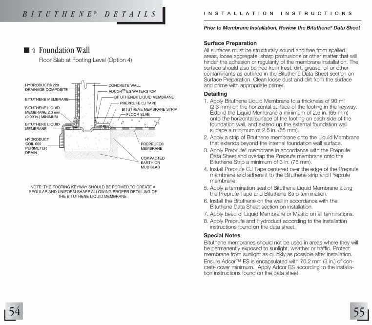
n 4 Foundation Wall Floor Slab at Footing Level (Option 4)
NOTE: THE FOOTING KEYWAY SHOULD BE FORMED TO CREATE A REGULAR AND UNIFORM SHAPE ALLOWING PROPER DETAILING OF
THE BITUTHENE LIQUID MEMBRANE.
55
Surface PreparationAll surfaces must be structurally sound and free from spalled areas, loose aggregate, sharp protrusions or other matter that will hinder the adhesion or regularity of the membrane installation. The surface should also be free from frost, dirt, grease, oil or other contaminants as outlined in the Bituthene Data Sheet section on Surface Preparation. Clean loose dust and dirt from the surface and prime with appropriate primer.
Detailing1. Apply Bituthene Liquid Membrane to a thickness of 90 mil
(2.3 mm) on the horizontal surface of the footing in the keyway. Extend the Liquid Membrane a minimum of 2.5 in. (65 mm) onto the horizontal surface of the footing on each side of the foundation wall, and extend up the external foundation wall surface a minimum of 2.5 in. (65 mm).
2. Apply a strip of Bituthene membrane onto the Liquid Membrane that extends beyond the internal foundation wall surface.
3. Apply Preprufe® membrane in accordance with the Preprufe Data Sheet and overlap the Preprufe membrane onto the Bituthene Strip a minimum of 3 in. (75 mm).
4. Install Preprufe CJ Tape centered over the edge of the Preprufe membrane and adhere it to the Bituthene strip and Preprufe membrane.
5. Apply a termination seal of Bituthene Liquid Membrane along the Preprufe Tape and Bituthene Strip termination.
6. Install the Bituthene on the wall in accordance with the Bituthene Data Sheet section on installation.
7. Apply bead of Liquid Membrane or Mastic on all terminations.8. Apply Preprufe and Hydroduct according to the installation
instructions found on the data sheet.
Special NotesBituthene membranes should not be used in areas where they will be permanently exposed to sunlight, weather or traffic. Protect membrane from sunlight as quickly as possible after installation.Ensure Adcor™ ES is encapsulated with 76.2 mm (3 in.) of con-crete cover minimum. Apply Adcor ES according to the installa-tion instructions found on the data sheet.
Prior to Membrane Installation, Review the Bituthene® Data Sheet
I N S T A L L A T I O N I N S T R U C T I O N SB I T U T H E N E ® D E T A I L S

56
n 6 Foundation Wall Elevated Floor Slab (Option 2)
57
Surface PreparationAll surfaces must be structurally sound and free from spalled areas, loose aggregate, sharp protrusions or other matter that will hinder the adhesion or regularity of the membrane installation. The surface should also be free from frost, dirt, grease, oil or other contaminants as outlined in the Bituthene® Data Sheet section on Surface Preparation. Clean loose dust and dirt from the surface and prime with appropriate primer.
Detailing1. Install the field membrane in accordance with the Bituthene
Data Sheet section on Installation2. Apply membrane to within 1 in. (25 mm) of base of wall.3. Apply Bituthene Liquid membrane in corner, extending over
membrane a minimum of 1 in. (25 mm).4. Terminate the Preprufe at the foundation wall. 5. Apply Preprufe Wall Termination detail PRE039.6. Apply Hydroduct 220 according to Hydroduct 220 Data Sheet.
Special NotesBituthene membranes should not be used in areas where they will be permanently exposed to sunlight, weather or traffic. Protect membrane from sunlight as quickly as possible after installation.Ensure Adcor™ ES is encapsulated with 76.2 mm (3 in.) of con-crete cover minimum. Apply Adcor ES according to the installa-tion instructions found on the data sheet.
Prior to Membrane Installation, Review the Bituthene® Data Sheet
I N S T A L L A T I O N I N S T R U C T I O N S
NOTE: NOT INTENDED FOR HYDROSTATIC CONDITIONS
B I T U T H E N E ® D E T A I L S

58
n 8 Foundation Wall Structural Slab
59
Surface PreparationAll surfaces must be structurally sound and free from spalled areas, loose aggregate, sharp protrusions or other matter that will hinder the adhesion or regularity of the membrane installation. The surface should also be free from frost, dirt, grease, oil or other contaminants as outlined in the Bituthene® Data Sheet section on Surface Preparation. Clean loose dust and dirt from the surface.
Detailing1. Install Preprufe membrane in accordance with the Preprufe Data
Sheet section on installation.2. Install a .75 in. (20 mm) fillet of Bituthene Liquid Membrane in
corner extending 2.5 in. (65 mm) onto wall and footing. Allow to cure.
3. Apply a 12 in. (300 mm) Bituthene strip centered over the outside corner of the footing.
4. Apply Bituthene membrane down wall, onto horizontal surface of the footing, and around the outside corner of the footing.
5. Extend Bituthene a minimum of 6 in. (150 mm) down vertical surface of footing, lapping onto Preprufe membrane. Do not apply primer to the back of the Preprufe for installation of the Bituthene.
6. Apply a bead of Liquid Membrane or Mastic on all terminations.7. Apply Hydroduct 220 according to Hydroduct 220 Data Sheet.
Special NotesProcor membranes should not be used in areas where they will be permanently exposed to sunlight, weather or traffic. Protect membrane from sunlight as quickly as possible after installation.Provide temporary protection for Preprufe at the tie-in location until the Bituthene tie-in is installed. The tie-in should be completed and backfilled as soon as possible.Ensure Adcor™ ES is encapsulated with 76.2 mm (3 in.) of con-crete cover minimum. Apply Adcor ES according to the installa-tion instructions found on the data sheet.
Prior to Membrane Installation, Review the Bituthene® Data Sheet
I N S T A L L A T I O N I N S T R U C T I O N S
B I T U T H E N E ® D E T A I L S

60
n 12 Plaza Deck to Wall Tie-in
61
Surface PreparationAll surfaces must be structurally sound and free from spalled areas, loose aggregate, sharp protrusions or other matter that will hinder the adhesion or regularity of the membrane installation. The surface should also be free from frost, dirt, grease, oil or other contaminants as outlined in the Bituthene® Data Sheet section on Surface Preparation. Clean loose dust and dirt from the surface and prime with appropriate primer.
Detailing1. Apply a 12 in. (300 mm) Bituthene Strip centered over the
outside corner between the top of the wall and the deck.2. Apply a 9 in. (225 mm) Bituthene Strip centered over the cold
joint between the wall and deck. Note this detail is for non-movement joints.
3. Apply field membrane in accordance with the Bituthene Data Sheet section on Installation.
4. Install membrane from the low point to the high point so that laps shed water.
5. Apply bead of Bituthene Liquid Membrane or Mastic on all terminations and T-Joints.
6. Apply Hydroduct 220 on the wall and Hydroduct 660 on the deck according to the respective Hydroduct Data Sheet.
Special NotesBituthene membranes should not be used in areas where they will be permanently exposed to sunlight, weather or traffic. Protect membrane from sunlight as quickly as possible after installation.Ensure Adcor™ ES is encapsulated with 76.2 mm (3 in.) of con-crete cover minimum. Apply Adcor ES according to the installa-tion instructions found on the data sheet.
Prior to Membrane Installation, Review the Bituthene® Data Sheet
I N S T A L L A T I O N I N S T R U C T I O N S
B I T U T H E N E ® D E T A I L S

62
n 14 Tie into Plaza Deck Waterproofing
63
Surface PreparationAll surfaces must be structurally sound and free from spalled areas, loose aggregate, sharp protrusions or other matter that will hinder the adhesion or regularity of the membrane installation. The surface should also be free from frost, dirt, grease, oil or other contaminants as outlined in the Bituthene® Data Sheet section on Surface Preparation. Clean loose dust and dirt from the surface and prime with appropriate primer.
Detailing1. Install Preprufe Membrane onto the vertical soil retention system
up to the level of the horizontal deck.2. Pour concrete and remove the top 12 in. (300 mm) of tempo-
rary soil retention to gain access to the wall.3. Apply a 12 in. (300 mm) Bituthene Strip centered over the
outside corner.4. Apply a Bituthene Strip centered over the cold joint. In this
detail, the Bituthene Strip is an extension of the Bituthene Strip for the outside corner. Do not apply primer to the back of the Preprufe for installation of the Bituthene.
5. Install the field membrane in accordance with the Bituthene Data Sheet section on Installation.
6. Install membrane from the low point to the high point so that laps shed water.
7. Apply bead of Bituthene Liquid Membrane or Mastic on all terminations and T-Joints.
8. Apply Hydroduct 220 on the wall and Hydroduct 660 on the deck according to the respective Hydroduct Data Sheet.
Special NotesBituthene membranes should not be used in areas where they will be permanently exposed to sunlight, weather or traffic. Protect membrane from sunlight as quickly as possible after installation.Provide temporary protection for Preprufe at the tie-in location until the Bituthene tie-in is installed. The tie-in should be completed and backfilled as soon as possible.Ensure Adcor™ ES is encapsulated with 76.2 mm (3 in.) of concrete cover minimum. Apply Adcor ES according to the installation instructions found on the data sheet.
Prior to Membrane Installation, Review the Bituthene® Data Sheet
I N S T A L L A T I O N I N S T R U C T I O N SB I T U T H E N E ® D E T A I L S
*NOTE: HYDRODUCT ON DECK AND TIE-IN TO WALL NOT SHOWN FOR CLARITY.

64
n 16 Penetration
65
Surface PreparationAll surfaces must be structurally sound and free from spalled areas, loose aggregate, sharp protrusions or other matter that will hinder the adhesion or regularity of the membrane installation. The surface should also be free from frost, dirt, grease, oil or other contaminants as outlined in the Bituthene® Data Sheet section on Surface Preparation. Clean loose dust and dirt from the surface and prime with appropriate primer.
Detailing1. Ensure the surface of the penetration is clean and grouted solid
to prevent movement.2. Apply Bituthene membrane onto substrate in accordance with
the Bituthene Data Sheet section on Installation. 3. Cut membrane to allow for penetration. Membrane should be
within 0.5 in. of penetration after cutting.4. Apply 90 mil (2.3 mm) thick Bituthene Liquid membrane 2.5 in.
(65 mm) onto penetration and onto membrane.5. Apply Hydroduct 220 according to Hydroduct 220 Data Sheet.
Special NotesBituthene membranes should not be used in areas where they will be permanently exposed to sunlight, weather or traffic. Protect membrane from sunlight as quickly as possible after installation.Ensure Adcor™ ES is encapsulated with 76.2 mm (3 in.) of con-crete cover minimum. Apply Adcor ES according to the installa-tion instructions found on the data sheet.
*NOTE: HYDRODUCT OR APPROvED PROTECTION COURSE NOT SHOWN FOR CLARITY
Prior to Membrane Installation, Review the Bituthene® Data Sheet
I N S T A L L A T I O N I N S T R U C T I O N S
B I T U T H E N E ® D E T A I L S
66
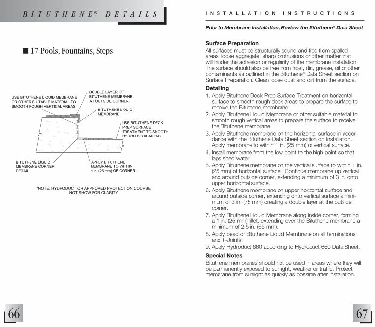
n 17 Pools, Fountains, Steps
67
Surface PreparationAll surfaces must be structurally sound and free from spalled areas, loose aggregate, sharp protrusions or other matter that will hinder the adhesion or regularity of the membrane installation. The surface should also be free from frost, dirt, grease, oil or other contaminants as outlined in the Bituthene® Data Sheet section on Surface Preparation. Clean loose dust and dirt from the surface.
Detailing1. Apply Bituthene Deck Prep Surface Treatment on horizontal
surface to smooth rough deck areas to prepare the surface to receive the Bituthene membrane.
2. Apply Bituthene Liquid Membrane or other suitable material to smooth rough vertical areas to prepare the surface to receive the Bituthene membrane.
3. Apply Bituthene membrane on the horizontal surface in accor-dance with the Bituthene Data Sheet section on Installation. Apply membrane to within 1 in. (25 mm) of vertical surface.
4. Install membrane from the low point to the high point so that laps shed water.
5. Apply Bituthene membrane on the vertical surface to within 1 in. (25 mm) of horizontal surface. Continue membrane up vertical and around outside corner, extending a minimum of 3 in. onto upper horizontal surface.
6. Apply Bituthene membrane on upper horizontal surface and around outside corner, extending onto vertical surface a mini-mum of 3 in. (75 mm) creating a double layer at the outside corner.
7. Apply Bituthene Liquid Membrane along inside corner, forming a 1 in. (25 mm) fillet, extending over the Bituthene membrane a minimum of 2.5 in. (65 mm).
8. Apply bead of Bituthene Liquid Membrane on all terminations and T-Joints.
9. Apply Hydroduct 660 according to Hydroduct 660 Data Sheet.
Special NotesBituthene membranes should not be used in areas where they will be permanently exposed to sunlight, weather or traffic. Protect membrane from sunlight as quickly as possible after installation.
*NOTE: HYDRODUCT OR APPROvED PROTECTION COURSE NOT SHOW FOR CLARITY
Prior to Membrane Installation, Review the Bituthene® Data Sheet
I N S T A L L A T I O N I N S T R U C T I O N SB I T U T H E N E ® D E T A I L S

68
n 18 Plaza Deck Deck to Wall Inside Corner (Option 1)
69
Surface PreparationAll surfaces must be structurally sound and free from spalled areas, loose aggregate, sharp protrusions or other matter that will hinder the adhesion or regularity of the membrane installation. The surface should also be free from frost, dirt, grease, oil or other contaminants as outlined in the Bituthene® Data Sheet section on Surface Preparation. Clean loose dust and dirt from the surface and prime with appropriate primer.
Detailing1. Apply Bituthene Deck Prep Surface Treatment on horizontal
surface to smooth rough deck areas to prepare the surface to receive the Bituthene membrane.
2. Apply Bituthene Liquid Membrane or other suitable material to smooth rough vertical areas to prepare the surface to receive the Bituthene membrane.
3. Apply Bituthene membrane on the horizontal surface in accor-dance with the Bituthene Data Sheet section on Installation. Apply membrane to within 1 in. (25 mm) of base of wall.
4. Install membrane from the low point to the high point so that laps shed water.
5. Apply Bituthene membrane on vertical wall to within 1 in. (25 mm) of base of wall.
6. Apply Bituthene Liquid Membrane along inside corner, forming a 1 in. fillet, extending over the Bituthene Membrane a minimum of 2.5 in. (65 mm).
7. Apply bead of Bituthene Liquid Membrane or Mastic on all terminations and T-joints.
Special NotesBituthene membranes should not be used in areas where they will be permanently exposed to sunlight, weather or traffic. Protect membrane from sunlight as quickly as possible after installation.Ensure Adcor™ ES is encapsulated with 76.2 mm (3 in.) of con-crete cover minimum. Apply Adcor ES according to the installa-tion instructions found on the data sheet.
*NOTE: HYDRODUCT OR APPROvED PROTECTION COURSE NOT SHOW FOR CLARITY
Prior to Membrane Installation, Review the Bituthene® Data Sheet
I N S T A L L A T I O N I N S T R U C T I O N S
B I T U T H E N E ® D E T A I L S

70
n 19 Plaza Deck Deck to Wall Inside Corner (Option 2)
71
Surface PreparationAll surfaces must be structurally sound and free from spalled areas, loose aggregate, sharp protrusions or other matter that will hinder the adhesion or regularity of the membrane installation. The surface should also be free from frost, dirt, grease, oil or other contaminants as outlined in the Bituthene® Data Sheet section on Surface Preparation. Clean loose dust and dirt from the surface and prime with appropriate primer.
Detailing1. Apply Bituthene Liquid membrane or other suitable material to
smooth rough vertical areas to prepare the surface to receive the Bituthene membrane.
2. Apply Bituthene Deck Prep surface treatment on horizontal surface to smooth rough deck areas to prepare the surface to receive the Bituthene membrane.
3. Apply Bituthene membrane on the horizontal surface in accor-dance with the Bituthene Data Sheet section on Installation. Apply membrane to within 1 in. (25 mm) of base of wall.
4. Form a .75 in. (20 mm) fillet of Bituthene Liquid Membrane in corner.
5. Apply a strip of Bituthene membrane 12 in. (300 mm) on horizontal, turn inside corner, and continue on vertical surface a minimum of 6 in. (150 mm) ( beyond the level of the finished surface.
6. Apply bead of Liquid membrane or Mastic on all terminations.7. Apply Hydroduct 220 according to Hydroduct 220 Data Sheet.
Special NotesBituthene membranes should not be used in areas where they will be permanently exposed to sunlight, weather or traffic. Protect membrane from sunlight as quickly as possible after installation.Ensure Adcor™ ES is encapsulated with 76.2 mm (3 in.) of con-crete cover minimum. Apply Adcor ES according to the installa-tion instructions found on the data sheet.
*NOTE: HYDRODUCT OR APPROvED PROTECTION COURSE NOT SHOW FOR CLARITY
Prior to Membrane Installation, Review the Bituthene® Data Sheet
I N S T A L L A T I O N I N S T R U C T I O N S
B I T U T H E N E ® D E T A I L S

72
n 22 Passive Joint Cover
*FOOTNOTE: FOR JOINT WHERE MOvEMENT IS EXPECTED (ACTIvE JOINTS) SEE EXPANSION JOINT COvER DETAIL BIT 024.
73
Surface PreparationAll surfaces must be structurally sound and free from spalled areas, loose aggregate, sharp protrusions or other matter that will hinder the adhesion or regularity of the membrane installation. The surface should also be free from frost, dirt, grease, oil or other contaminants as outlined in the Bituthene® Data Sheet section on Surface Preparation. Clean loose dust and dirt from the surface and prime with appropriate primer.
Detailing1. Apply Bituthene Deck Prep Surface Treatment on horizontal
surface to smooth rough deck areas to prepare the surface to receive the Bituthene membrane.
2. Apply backer rod in passive joint and fill joint with Bituthene Liquid Membrane or appropriate sealant.
3. Position 9 in. (225 mm) Bituthene membrane strip centered over the passive joint.
4. Apply Bituthene membrane on the horizontal surface in accor-dance with the Bituthene Data Sheet section on Installation.
5. Install membrane from the low point to the high point so that laps shed water.
6. Apply bead of Bituthene Liquid Membrane or Mastic on all terminations and T-joints.
7. Apply Hydroduct 660 according to Hydroduct 660 Data Sheet
Special NotesBituthene membranes should not be used in areas where they will be permanently exposed to sunlight, weather or traffic. Protect membrane from sunlight as quickly as possible after installation.
Prior to Membrane Installation, Review the Bituthene® Data Sheet
I N S T A L L A T I O N I N S T R U C T I O N S
B I T U T H E N E ® D E T A I L S

74
n 24 Expansion Joint Cover Deck or Wall
*FOOTNOTES: · FOR JOINT WIDTHS UP TO 2 IN. (51 MM) WITH A MAXIMUM
OF 1 IN. (25 MM) MOvEMENT. · IF EXPECTED MOvEMENT IS LESS THAN 0.5 IN. (13 MM) A 6 IN. (150 MM)
INvERTED STRIP IS ACCEPTABLE.
75
Surface PreparationAll surfaces must be structurally sound and free from spalled areas, loose aggregate, sharp protrusions or other matter that will hinder the adhesion or regularity of the membrane installation. The surface should also be free from frost, dirt, grease, oil or other contaminants as outlined in the Bituthene® Data Sheet section on Surface Preparation. Clean loose dust and dirt from the surface and prime with appropriate primer.
Detailing1. Install expansion joint system, by other manufacturer, according
to manufacturer’s installation instructions.2. Apply Bituthene Deck Prep Surface Treatment on horizontal
surface to smooth rough deck areas to prepare the surface to receive the Bituthene membrane.
3. Apply Bituthene membrane on the horizontal surface in accor-dance with the Bituthene Data Sheet section on Installation. Install membrane from the low point to the high point so that laps shed water. Terminate at edge of expansion joint.
4. Apply 9 in. (225 mm) inverted Bituthene membrane strip centered over the expansion joint.
5. Apply 18 in. (450 mm) Bituthene membrane strip centered over the expansion joint and lapped onto field membrane.
6. Apply full width, 36 in. (900 mm) Bituthene membrane strip centered over the expansion joint cover and lapped onto the field membrane.
7. Apply bead of Bituthene Liquid Membrane or Bituthene Mastic on all terminations and T-joints.
8. Apply Hydroduct 660 according to Hydroduct 660 Data Sheet.
Special NotesBituthene membranes should not be used in areas where they will be permanently exposed to sunlight, weather or traffic. Protect membrane from sunlight as quickly as possible after installation.
Prior to Membrane Installation, Review the Bituthene® Data Sheet
I N S T A L L A T I O N I N S T R U C T I O N S
B I T U T H E N E ® D E T A I L S

76
n 25 Expansion Joint Cover Deck to Wall Junction
77
Surface PreparationAll surfaces must be structurally sound and free from spalled areas, loose aggregate, sharp protrusions or other matter that will hinder the adhesion or regularity of the membrane installation. The surface should also be free from frost, dirt, grease, oil or other contaminants as outlined in the Bituthene® Data Sheet section on Surface Preparation. Clean loose dust and dirt from the surface and prime with appropriate primer.
Detailing1. Apply Bituthene Deck Prep surface treatment on horizontal
surface to smooth rough deck areas to prepare the surface to receive the Bituthene membrane.
2. Install expansion joint system, by other manufacturer, according to manufacturer’s installation instructions.
3. Apply Bituthene membrane on the horizontal surface in accor-dance with the Bituthene Data Sheet section on Installation. Terminate at edge of expansion joint.
4. Apply 9 in. (225 mm) inverted Bituthene membrane strip centered over the expansion joint with half of the strip on the horizontal surface and half of the strip on the vertical surface.
5. Apply 18 in. (450 mm) Bituthene membrane strip centered over the expansion joint and lapped onto field membrane. Half of strip should be on horizontal surface and half of strip should be on the vertical surface.
6. Apply a full width of Bituthene membrane on top of the 18 in. (450 mm) strip, with half the membrane on the horizontal surface and half the membrane on the vertical surface.
7. Install a termination bar at the top leading edge of the Bituthene on the wall and seal with Liquid Membrane or Mastic.
8. Apply bead of Liquid membrane or Mastic on all terminations.9. Apply Hydroduct 220 according to Hydroduct 220 Data Sheet.
Special NotesBituthene membranes should not be used in areas where they will be permanently exposed to sunlight, weather or traffic. Protect membrane from sunlight as quickly as possible after installation.
Prior to Membrane Installation, Review the Bituthene® Data Sheet
I N S T A L L A T I O N I N S T R U C T I O N S
B I T U T H E N E ® D E T A I L S
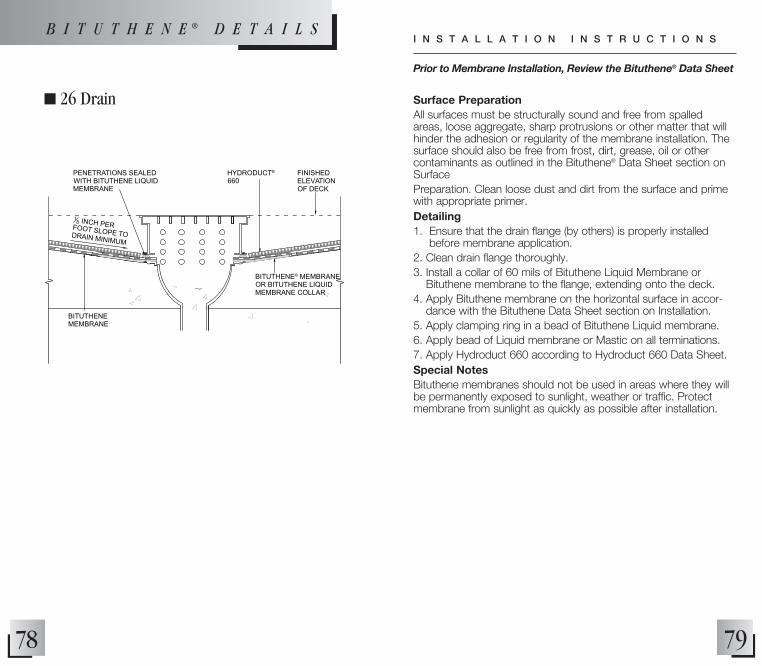
Surface PreparationAll surfaces must be structurally sound and free from spalled areas, loose aggregate, sharp protrusions or other matter that will hinder the adhesion or regularity of the membrane installation. The surface should also be free from frost, dirt, grease, oil or other contaminants as outlined in the Bituthene® Data Sheet section on SurfacePreparation. Clean loose dust and dirt from the surface and prime with appropriate primer. Detailing1. Ensure that the drain flange (by others) is properly installed
before membrane application.2. Clean drain flange thoroughly.3. Install a collar of 60 mils of Bituthene Liquid Membrane or
Bituthene membrane to the flange, extending onto the deck.4. Apply Bituthene membrane on the horizontal surface in accor-
dance with the Bituthene Data Sheet section on Installation. 5. Apply clamping ring in a bead of Bituthene Liquid membrane.6. Apply bead of Liquid membrane or Mastic on all terminations.7. Apply Hydroduct 660 according to Hydroduct 660 Data Sheet.Special NotesBituthene membranes should not be used in areas where they will be permanently exposed to sunlight, weather or traffic. Protect membrane from sunlight as quickly as possible after installation.
Prior to Membrane Installation, Review the Bituthene® Data Sheet
I N S T A L L A T I O N I N S T R U C T I O N S
n 26 Drain
78
B I T U T H E N E ® D E T A I L S
18
INCH
PER
FOOT SLOPE
TO
DRAIN
MINIMUM
FINISHED ELEVATION OF DECK
BITUTHENE® MEMBRANE OR BITUTHENE LIQUID MEMBRANE COLLAR
PENETRATIONS SEALED WITH BITUTHENE LIQUID MEMBRANE
HYDRODUCT®
660
BITUTHENE MEMBRANE
79

Preprufe®
Application Instructions....................................80
Details • Foundation Wall –
Floor Slab at Footing Level – Option 1 ...................................82• Foundation Wall –
Floor Slab at Footing Level – Option 2 ...................................84• Foundation Wall –
Floor Slab at Footing Level – Option 3 ...................................86• Foundation Wall
Floor Slab at Footing Level – Option 4 ...................................88• Foundation Wall – Elevated Floor Slab – Option 1 .................90• Foundation Wall – Elevated Floor Slab – Option 2 .................92• Tie into Preprufe at Structural Slab ........................................94• Foundation Wall – Structural Slab .........................................96• Blind Side Wall to Slab Tie-in ................................................98• Below Slab Drainage with Hydroduct Connector Tee ........... 100• End Lap Detail for Wall or Slab – Option 1 ................................ 102• End Lap Detail for Wall or Slab – Option 2 .............................. 104• Inside Corner ....................................................................... 106• Pipe Penetration .................................................................. 108• Straight Edge Penetration .................................................... 110• Outside Corner .................................................................... 112• Column – Option 1 .............................................................. 114• Column – Option 2 .............................................................. 116• Wall Termination for Elevated Slab ...................................... 118• Wall Termination to Bituthene Membrane ................................. 120• Wall Termination to Procor Membrane ..................................... 122• Joint ...............................................................................................124• Grade Beam Pile Cap – Option 1 .......................................... 126• Grade Beam Pile Cap – Option 2 .......................................... 128• Tie into Bituthene Wall Waterproofing – Plan View .............. 132• Preprufe Tie-Back Cover ...................................................... 134• Soil Retention Tie-Back Cover – Custom Box Cover ............ 136• Top Termination and End Lap .............................................. 138• Rebar, Dowel and All-Thread Penetration .............................. 140• Preprufe Preformed Inside Corners ..................................... 142• Preprufe Preformed Outside Corners ................................... 144• Preprufe Preformed Inside Caps .......................................... 146• Preprufe Preformed Outside Caps ....................................... 148

• For vertical and horizontal appli-cations in cool temperatures or damp conditions, gently warm side laps or use Preprufe Tape LT.
3. Vertical Application • Apply Preprufe membrane in a
convenient length with HDPE film side facing the prepared substrate.
• Fasten to substrate along the top edge with large head nails, roofing nails or staples. Top termination should be secured with termination bar and fasteners.
• For lengths greater than 8 ft (2.4 m), additional fastening at 2 ft (0.6 m) intervals along the uncoated edge prior to making the side lap is recommended. (Picture 6)
• Roll side lap.• Overlap ends of membrane a
minimum of 3 in. (75 mm).• Center Preprufe Tape over
end laps and roll firmly. If top termination is to be covered with concrete, a strip of tape should also be centered over the termination bar. (Refer to Detail Drawing #48 on page 136)
• Remove release liner.
4. Visual Work Inspection• Inspect the membrane for damage
before placing of reinforcing steel, formwork and concrete.
• Repair slices and small punctures which are less than 0.5 in. (13 mm) by applying Preprufe Tape over the damages area and roll firmly.
• Repair holes and punctures greater than 0.5 in. (13 mm) by
applying a patch of Preprufe membrane to extend 6 in. (150 mm) beyond the damaged area. Seal the terminations of the patch with Preprufe Tape.
• Ensure plastic release liner is removed from all areas of Preprufe membrane and tape.
5. Concrete Placement• Cast concrete within 56 days
(42 days in hot climates) of application of the membrane.
• Concrete must be placed carefully to avoid damage to the membrane.
• For shotcrete placement, contact your local Grace sales representative.
81
(5) Tape end laps
A
B
C
(6) Fasten to substrate
Preprufe® Waterproofing Membranes
(1) Clean surface
(2) Apply membrane
(3) Remove liner
(4) Roll laps
1. Prepare Substrate• Substrates must be sound and
solid to eliminate movement during the concrete pour.
• Substrates must be regular and smooth with no gaps or voids greater than 0.5 in. (13 mm).
• Substrates must be free of loose aggregate and sharp protrusions. (Picture 1)
• Surface does not need to be dry, but standing water must be removed.
• Applications may require the use of Hydroduct Drainage Composite or plywood to provide a suitable substrate over the soil retention system.
2. Horizontal Application • Apply Preprufe membrane with
the HDPE film side facing the prepared substrate and the treated white coating surface facing the concrete to be poured. (Picture 2)
• Overlap succeeding sheets by a minimum of 3 in. (75 mm).
• Remove release liner. (Picture 3)• Roll side lap. (Picture 4)• Overlap ends of membrane a
minimum of 3 in. (75 mm).• Center Preprufe Tape over end
laps and roll firmly. (Refer to Detail Drawings #31 & #32
80
For complete application instructions refer to the technical data sheet for Preprufe found at graceconstruction.com.
A P P L I C A T I O N I N S T R U C T I O N S

82 83
n 1 Foundation Wall Floor Slab at Footing Level (Option 1)
P R E P R U F E ® D E T A I L S
Surface PreparationAll surfaces must be sound and solid to eliminate movement dur-ing the concrete pour. Substrate must be regular and smooth with no gaps or voids greater than 0.5 in. (13 mm). The surface should also be free from loose aggregate and sharp protrusions as out-lined in the Preprufe® Data Sheet section on Surface Preparation.
Detailing1. Over rough surfaces, install a 1 inch fillet of Bituthene® Liquid
Membrane in inside corner at the base of the wall.2. Apply Preprufe® Tape at the termination of the Preprufe field
membrane to ensure good adhesion with the Procor mem-brane.
3. Install a pre-treatment of 60 mils (1.5 mm) of Procor in the inside corner at the base of the wall, extending, at minimum, 6 in. (150 mm) onto the footing and 6 in. (150 mm) up the wall.
4. Install a pre-treatment of 60 mils (1.5 mm) of Procor on the outside corner of the footing, extending a down to completely cover the Preprufe Tape and a minimum of 6 in. (150 mm) onto the horizontal surface of the footing.
5. Install the field membrane in accordance with the Procor Data Sheet section on Installation. Extend Procor completely over Preprufe tape detail
6. Apply Hydroduct 220 according to Hydroduct 220 Data Sheet.
Special NotesPreprufe membranes should not be used in areas where they will be permanently exposed to sunlight, weather or traffic. Protect membrane from sunlight as quickly as possible after installation.Provide temporary protection for Preprufe at the tie-in location until the Procor tie-in is installed. The tie-in should be completed and backfilled as soon as possible.Ensure Adcor™ ES is encapsulated with 76.2 mm (3 in.) of con-crete cover minimum. Apply Adcor ES according to the installa-tion instructions found on the data sheet.
Prior to Membrane Installation, Review the Preprufe® Data Sheet
I N S T A L L A T I O N I N S T R U C T I O N S
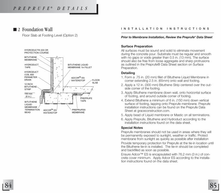
84 85
n 2 Foundation Wall Floor Slab at Footing Level (Option 2) Prior to Membrane Installation, Review the Preprufe® Data Sheet
I N S T A L L A T I O N I N S T R U C T I O N S
P R E P R U F E ® D E T A I L S
Surface PreparationAll surfaces must be sound and solid to eliminate movement during the concrete pour. Substrate must be regular and smooth with no gaps or voids greater than 0.5 in. (13 mm). The surface should also be free from loose aggregate and sharp protrusions as outlined in the Preprufe® Data Sheet section on Surface Preparation.
Detailing1. Form a .75 in. (20 mm) fillet of Bituthene Liquid Membrane in
corner extending 2.5 in. (65mm) onto wall and footing.2. Apply a 12 in. (300 mm) Bituthene Strip centered over the out-
side corner of the footing.3. Apply Bituthene membrane down wall, onto horizontal surface
of footing, and around outside corner of footing.4. Extend Bituthene a minimum of 6 in. (150 mm) down vertical
surface of footing, lapping onto Preprufe membrane. Preprufe installation instructions can be found on the Preprufe Data Sheet at graceconstruction.com.
5. Apply bead of Liquid membrane or Mastic on all terminations.6. Apply Preprufe, Bituthene and Hydroduct according to the
installation instructions found on the data sheet.
Special NotesPreprufe membranes should not be used in areas where they will be permanently exposed to sunlight, weather or traffic. Protect membrane from sunlight as quickly as possible after installationProvide temporary protection for Preprufe at the tie-in location until the Bituthene tie-in is installed. The tie-in should be completed and backfilled as soon as possible.Ensure Adcor™ ES is encapsulated with 76.2 mm (3 in.) of con-crete cover minimum. Apply Adcor ES according to the installa-tion instructions found on the data sheet.
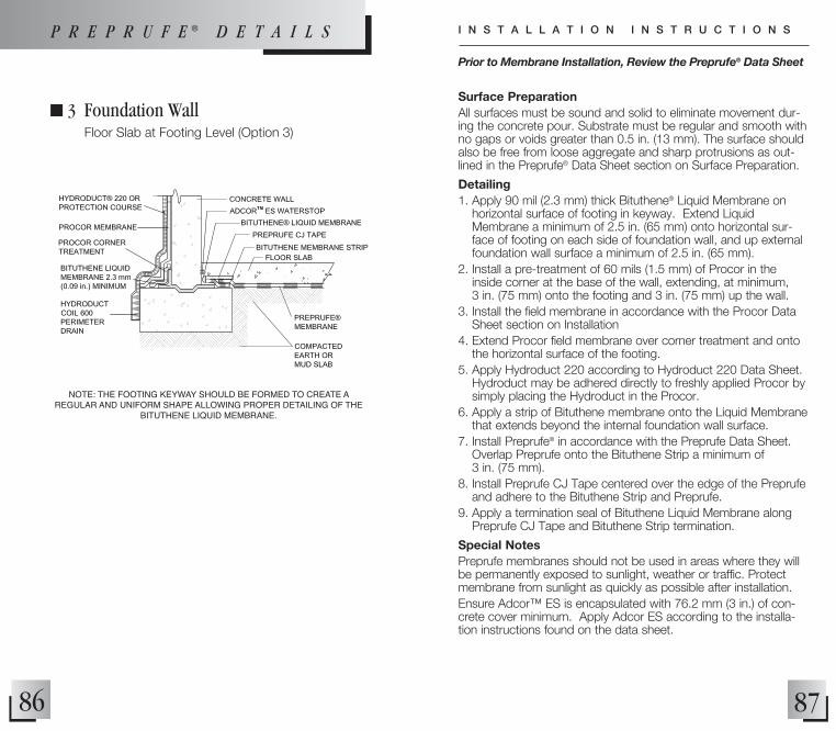
86 87
n 3 Foundation Wall Floor Slab at Footing Level (Option 3)
Surface PreparationAll surfaces must be sound and solid to eliminate movement dur-ing the concrete pour. Substrate must be regular and smooth with no gaps or voids greater than 0.5 in. (13 mm). The surface should also be free from loose aggregate and sharp protrusions as out-lined in the Preprufe® Data Sheet section on Surface Preparation.
Detailing1. Apply 90 mil (2.3 mm) thick Bituthene® Liquid Membrane on
horizontal surface of footing in keyway. Extend Liquid Membrane a minimum of 2.5 in. (65 mm) onto horizontal sur-face of footing on each side of foundation wall, and up external foundation wall surface a minimum of 2.5 in. (65 mm).
2. Install a pre-treatment of 60 mils (1.5 mm) of Procor in the inside corner at the base of the wall, extending, at minimum, 3 in. (75 mm) onto the footing and 3 in. (75 mm) up the wall.
3. Install the field membrane in accordance with the Procor Data Sheet section on Installation
4. Extend Procor field membrane over corner treatment and onto the horizontal surface of the footing.
5. Apply Hydroduct 220 according to Hydroduct 220 Data Sheet. Hydroduct may be adhered directly to freshly applied Procor by simply placing the Hydroduct in the Procor.
6. Apply a strip of Bituthene membrane onto the Liquid Membrane that extends beyond the internal foundation wall surface.
7. Install Preprufe® in accordance with the Preprufe Data Sheet. Overlap Preprufe onto the Bituthene Strip a minimum of 3 in. (75 mm).
8. Install Preprufe CJ Tape centered over the edge of the Preprufe and adhere to the Bituthene Strip and Preprufe.
9. Apply a termination seal of Bituthene Liquid Membrane along Preprufe CJ Tape and Bituthene Strip termination.
Special NotesPreprufe membranes should not be used in areas where they will be permanently exposed to sunlight, weather or traffic. Protect membrane from sunlight as quickly as possible after installation.Ensure Adcor™ ES is encapsulated with 76.2 mm (3 in.) of con-crete cover minimum. Apply Adcor ES according to the installa-tion instructions found on the data sheet.
NOTE: THE FOOTING KEYWAY SHOULD BE FORMED TO CREATE A REGULAR AND UNIFORM SHAPE ALLOWING PROPER DETAILING OF THE
BITUTHENE LIQUID MEMBRANE.
Prior to Membrane Installation, Review the Preprufe® Data Sheet
I N S T A L L A T I O N I N S T R U C T I O N SP R E P R U F E ® D E T A I L S
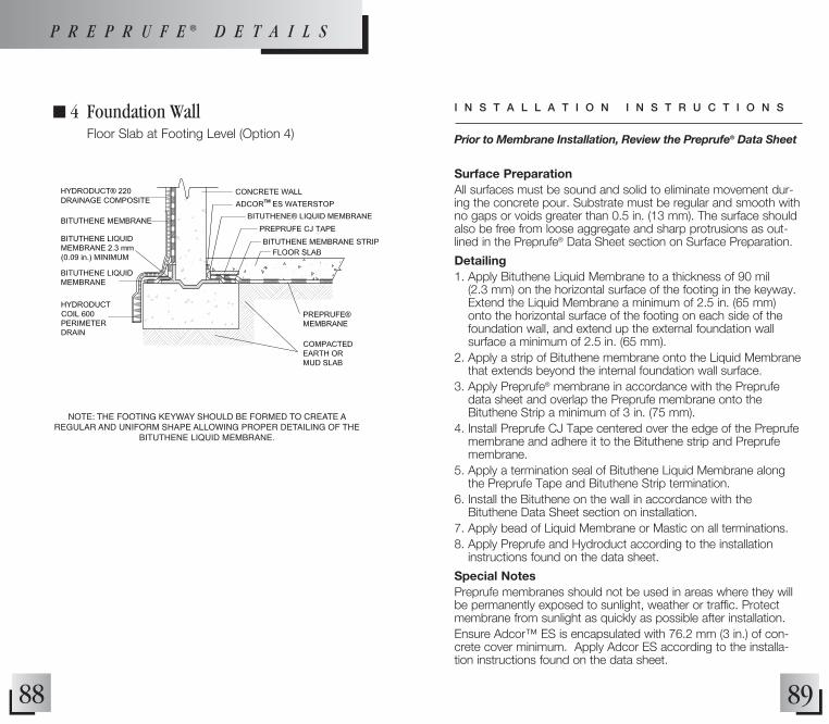
88
n 4 Foundation Wall Floor Slab at Footing Level (Option 4)
NOTE: THE FOOTING KEYWAY SHOULD BE FORMED TO CREATE A REGULAR AND UNIFORM SHAPE ALLOWING PROPER DETAILING OF THE
BITUTHENE LIQUID MEMBRANE.
89
Surface PreparationAll surfaces must be sound and solid to eliminate movement dur-ing the concrete pour. Substrate must be regular and smooth with no gaps or voids greater than 0.5 in. (13 mm). The surface should also be free from loose aggregate and sharp protrusions as out-lined in the Preprufe® Data Sheet section on Surface Preparation.
Detailing1. Apply Bituthene Liquid Membrane to a thickness of 90 mil
(2.3 mm) on the horizontal surface of the footing in the keyway. Extend the Liquid Membrane a minimum of 2.5 in. (65 mm) onto the horizontal surface of the footing on each side of the foundation wall, and extend up the external foundation wall surface a minimum of 2.5 in. (65 mm).
2. Apply a strip of Bituthene membrane onto the Liquid Membrane that extends beyond the internal foundation wall surface.
3. Apply Preprufe® membrane in accordance with the Preprufe data sheet and overlap the Preprufe membrane onto the Bituthene Strip a minimum of 3 in. (75 mm).
4. Install Preprufe CJ Tape centered over the edge of the Preprufe membrane and adhere it to the Bituthene strip and Preprufe membrane.
5. Apply a termination seal of Bituthene Liquid Membrane along the Preprufe Tape and Bituthene Strip termination.
6. Install the Bituthene on the wall in accordance with the Bituthene Data Sheet section on installation.
7. Apply bead of Liquid Membrane or Mastic on all terminations.8. Apply Preprufe and Hydroduct according to the installation
instructions found on the data sheet.
Special NotesPreprufe membranes should not be used in areas where they will be permanently exposed to sunlight, weather or traffic. Protect membrane from sunlight as quickly as possible after installation.Ensure Adcor™ ES is encapsulated with 76.2 mm (3 in.) of con-crete cover minimum. Apply Adcor ES according to the installa-tion instructions found on the data sheet.
Prior to Membrane Installation, Review the Preprufe® Data Sheet
I N S T A L L A T I O N I N S T R U C T I O N S
P R E P R U F E ® D E T A I L S

90
n 5 Foundation Wall Elevated Floor Slab (Option 1)
NOTE: NOT INTENDED FOR HYDROSTATIC CONDITIONS
91
Surface PreparationAll surfaces must be sound and solid to eliminate movement dur-ing the concrete pour. Substrate must be regular and smooth with no gaps or voids greater than 0.5 in. (13 mm). The surface should also be free from loose aggregate and sharp protrusions as out-lined in the Preprufe® Data Sheet section on Surface Preparation.
Detailing1. Install the Procor and Preprufe membranes in accordance with
the Procor and Preprufe Data Sheet section on installation.2. Apply Hydroduct 220 according to Hydroduct 220 Data Sheet.
Hydroduct may be adhered directly to freshly sprayed Procor by simply placing the Hydroduct in the wet Procor.
3. Terminate the Preprufe at the foundation wall. 4. Apply Preprufe Wall Termination detail PRE039.
Special NotesPreprufe membranes should not be used in areas where they will be permanently exposed to sunlight, weather or traffic. Protect membrane from sunlight as quickly as possible after installation.Ensure Adcor™ ES is encapsulated with 76.2 mm (3 in.) of con-crete cover minimum. Apply Adcor ES according to the installa-tion instructions found on the data sheet.
Prior to Membrane Installation, Review the Preprufe® Data Sheet
I N S T A L L A T I O N I N S T R U C T I O N S
P R E P R U F E ® D E T A I L S
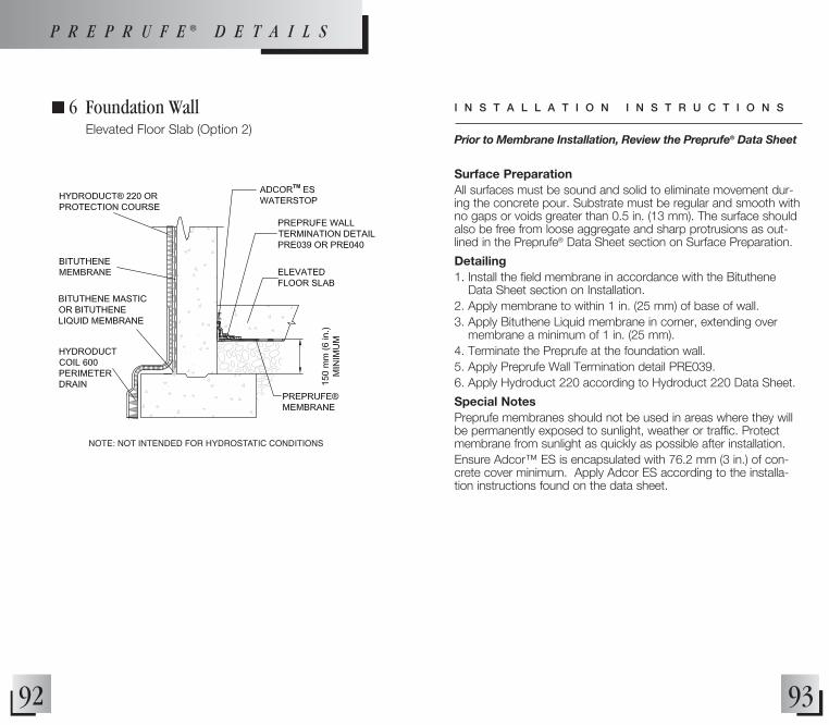
92
n 6 Foundation Wall Elevated Floor Slab (Option 2)
93
Surface PreparationAll surfaces must be sound and solid to eliminate movement dur-ing the concrete pour. Substrate must be regular and smooth with no gaps or voids greater than 0.5 in. (13 mm). The surface should also be free from loose aggregate and sharp protrusions as out-lined in the Preprufe® Data Sheet section on Surface Preparation.
Detailing1. Install the field membrane in accordance with the Bituthene
Data Sheet section on Installation.2. Apply membrane to within 1 in. (25 mm) of base of wall.3. Apply Bituthene Liquid membrane in corner, extending over
membrane a minimum of 1 in. (25 mm).4. Terminate the Preprufe at the foundation wall. 5. Apply Preprufe Wall Termination detail PRE039.6. Apply Hydroduct 220 according to Hydroduct 220 Data Sheet.
Special NotesPreprufe membranes should not be used in areas where they will be permanently exposed to sunlight, weather or traffic. Protect membrane from sunlight as quickly as possible after installation.Ensure Adcor™ ES is encapsulated with 76.2 mm (3 in.) of con-crete cover minimum. Apply Adcor ES according to the installa-tion instructions found on the data sheet.
Prior to Membrane Installation, Review the Preprufe® Data Sheet
I N S T A L L A T I O N I N S T R U C T I O N S
NOTE: NOT INTENDED FOR HYDROSTATIC CONDITIONS
P R E P R U F E ® D E T A I L S

94 95
Surface PreparationAll surfaces must be sound and solid to eliminate movement dur-ing the concrete pour. Substrate must be regular and smooth with no gaps or voids greater than 0.5 in. (13 mm). The surface should also be free from loose aggregate and sharp protrusions as out-lined in the Preprufe® Data Sheet section on Surface Preparation.
Detailing1. Install Preprufe membrane in accordance with the Preprufe Data
Sheet section on installation.2. Over rough surfaces, apply a 1 in. (25 mm) fillet of Bituthene
Liquid Membrane to inside corner at the base of the wall.3. Install a pre-treatment of 60 mils (1.5 mm) of Procor in the
inside corner at the base of the wall, extending at minimum of 3 in. (75 mm) onto the footing and 3 in. (75 mm) up the wall.
4. Apply Preprufe Tape at the termination of the Preprufe field membrane to ensure good adhesion of the Procor membrane.
5. Install the field membrane in accordance with the Procor Data Sheet section on Installation. Extend Procor completely over Preprufe Tape detail.
6. Apply Hydroduct 220 according to Hydroduct 220 Data Sheet.
Special NotesPreprufe membranes should not be used in areas where they will be permanently exposed to sunlight, weather or traffic. Protect membrane from sunlight as quickly as possible after installation.Provide temporary protection for Preprufe at the tie-in location until the Procor tie-in is installed. The tie-in should be completed and backfilled as soon as possible.Ensure Adcor™ ES is encapsulated with 76.2 mm (3 in.) of con-crete cover minimum. Apply Adcor ES according to the installa-tion instructions found on the data sheet.
n 7 Tie into Preprufe® At Structural Slab
Prior to Membrane Installation, Review the Preprufe® Data Sheet
I N S T A L L A T I O N I N S T R U C T I O N S
P R E P R U F E ® D E T A I L S
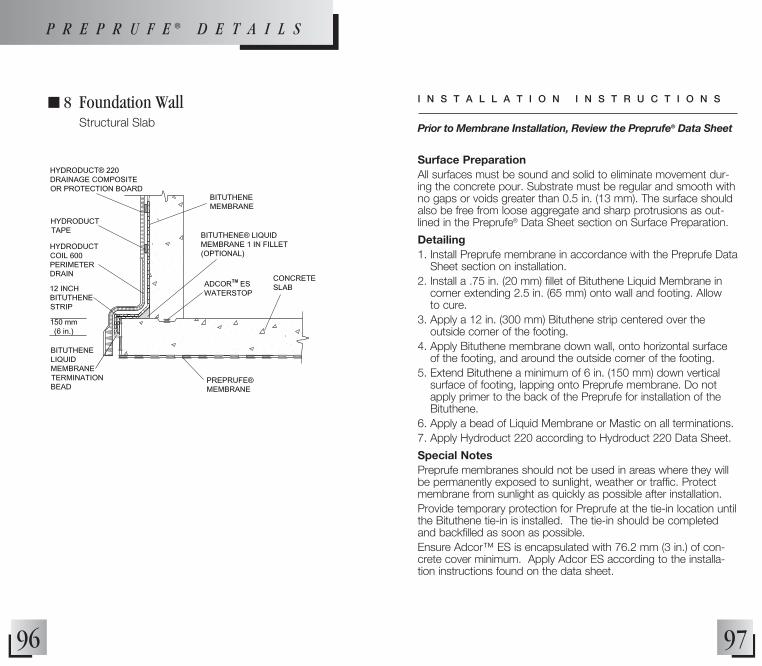
96
n 8 Foundation Wall Structural Slab
97
Surface PreparationAll surfaces must be sound and solid to eliminate movement dur-ing the concrete pour. Substrate must be regular and smooth with no gaps or voids greater than 0.5 in. (13 mm). The surface should also be free from loose aggregate and sharp protrusions as out-lined in the Preprufe® Data Sheet section on Surface Preparation.
Detailing1. Install Preprufe membrane in accordance with the Preprufe Data
Sheet section on installation.2. Install a .75 in. (20 mm) fillet of Bituthene Liquid Membrane in
corner extending 2.5 in. (65 mm) onto wall and footing. Allow to cure.
3. Apply a 12 in. (300 mm) Bituthene strip centered over the outside corner of the footing.
4. Apply Bituthene membrane down wall, onto horizontal surface of the footing, and around the outside corner of the footing.
5. Extend Bituthene a minimum of 6 in. (150 mm) down vertical surface of footing, lapping onto Preprufe membrane. Do not apply primer to the back of the Preprufe for installation of the Bituthene.
6. Apply a bead of Liquid Membrane or Mastic on all terminations.7. Apply Hydroduct 220 according to Hydroduct 220 Data Sheet.
Special NotesPreprufe membranes should not be used in areas where they will be permanently exposed to sunlight, weather or traffic. Protect membrane from sunlight as quickly as possible after installation.Provide temporary protection for Preprufe at the tie-in location until the Bituthene tie-in is installed. The tie-in should be completed and backfilled as soon as possible.Ensure Adcor™ ES is encapsulated with 76.2 mm (3 in.) of con-crete cover minimum. Apply Adcor ES according to the installa-tion instructions found on the data sheet.
Prior to Membrane Installation, Review the Preprufe® Data Sheet
I N S T A L L A T I O N I N S T R U C T I O N S
P R E P R U F E ® D E T A I L S

98
n 9 Blind Side Wall to Slab Tie-in
99
Surface PreparationAll surfaces must be sound and solid to eliminate movement during the concrete pour. Substrate must be regular and smooth with no gaps or voids greater than 0.5 in. (13 mm). The surface should also be free from loose aggregate and sharp protrusions as outlined in the Preprufe® Data Sheet section on Surface Preparation.
Detailing1. Install Preprufe Membrane over the mud slab or compacted
earth as detailed in horizontal and vertical applications on the Preprufe Data Sheet.
2. Continue onto the vertical surface of the prepared soil retention system a minimum of 18 in. (450 mm) above the finished eleva-tion of the structural floor slab. It is good practice to extend the Preprufe above the height of the rebar from the slab.
3. Apply Preprufe CJ Tape to the Preprufe membrane centered over the finished elevation of the concrete slab.
4. Secure the top of the membrane to temporarily hold it in place on the vertical substrate. Care should be taken to prevent damage to this exposed membrane from concrete back-splash as well as slag from rebar welding in wall forms, by keeping the release liner on and protected with protection board, plywood or other material.
5. If the exposed membrane above the slab is contaminated with concrete oversplash is the lap area, it must be cleaned down to good material before adhering Preprufe Tape.
6. Install Preprufe Membrane over the prepared vertical soil retention system according to standard application instructions on the Preprufe Data Sheet.
7. Unfasten the vertical length of the Preprufe Membrane that extends above the slab and tuck the Preprufe 160R behind the 18 in. (450 mm) length of Preprufe 300R, ensuring a minimum 3 in. (75 mm) lap.
8. Install Preprufe Tape centered over the lap.9. Remove release liner and roll tape to ensure good adhesion
using steel or vinyl cylindrical and Vee roller.
Special NotesPreprufe membranes should not be used in areas where they will be permanently exposed to sunlight, weather or traffic. Protect membrane from sunlight as quickly as possible after installation.Ensure Adcor™ ES is encapsulated with 76.2 mm (3 in.) of concrete cover minimum. Apply Adcor ES according to the installation instructions found on the data sheet.
Prior to Membrane Installation, Review the Preprufe® Data Sheet
I N S T A L L A T I O N I N S T R U C T I O N SP R E P R U F E ® D E T A I L S

101100
n 10 Below Slab Drainage with Hydroduct® Connector Tee
Surface PreparationAll surfaces must be sound and solid to eliminate movement dur-ing the concrete pour. Substrate must be regular and smooth with no gaps or voids greater than 0.5 in. (13 mm). The surface should also be free from loose aggregate and sharp protrusions as out-lined in the Preprufe® Data Sheet section on Surface Preparation.
Detailing1. Install Preprufe Membrane over the compacted drainage fill as
detailed in horizontal applications in the Preprufe Data Sheet.2. Install Preprufe Membrane and Hydroduct on the soil retention
system as detailed in vertical applications in the Preprufe Data Sheet.
3. Apply the Hydroduct Connector Tee to the face of the Hydroduct as described in the Hydroduct Coil 600 Data Sheet.
4. Connect a 4 in. drainage pipe on the connector tee and extend to an appropriate drainage area.
5. Seal all joints of the drainage system with 3 in. underground tape.
Special NotesPreprufe membranes should not be used in areas where they will be permanently exposed to sunlight, weather or traffic. Protect membrane from sunlight as quickly as possible after installation.Ensure Adcor™ ES is encapsulated with 76.2 mm (3 in.) of con-crete cover minimum. Apply Adcor ES according to the installa-tion instructions found on the data sheet.
Prior to Membrane Installation, Review the Preprufe® Data Sheet
I N S T A L L A T I O N I N S T R U C T I O N S
NOTE: NOT INTENDED FOR HYDROSTATIC CONDITIONS
P R E P R U F E ® D E T A I L S

103102
n 31 End Lap Detail for Wall or Slab (Option 1) Tape applied after installation of side laps
Surface PreparationAll surfaces must be sound and solid to eliminate movement dur-ing the concrete pour. Substrate must be regular and smooth with no gaps or voids greater than 0.5 in. (13 mm). The surface should also be free from loose aggregate and sharp protrusions as out-lined in the Preprufe® Data Sheet section on Surface Preparation.
Detailing1. Apply Hydroduct® according to Hydroduct Data Sheet.2. Install Preprufe Membrane and tape in order as shown by
numbers.3. Overlap the ends of the membrane a minimum of 3 in. (75 mm)
and remove release liner from both membranes.4. Apply Preprufe Tape over the end lap as shown and roll firmly. 5. Apply tape a minimum of 2 in. (50 mm) beyond all edges of
membrane that are not sealed by the selvedge.6. Remove release liner from tape and discard.
Special NotesPreprufe membranes should not be used in areas where they will be permanently exposed to sunlight, weather or traffic. Protect membrane from sunlight as quickly as possible after installation.
NOTE: INSTALL PREPRUFE® MEMBRANE AND TAPE IN ORDER AS SHOWN BY NUMBERS.
Prior to Membrane Installation, Review the Preprufe® Data Sheet
I N S T A L L A T I O N I N S T R U C T I O N S
P R E P R U F E ® D E T A I L S
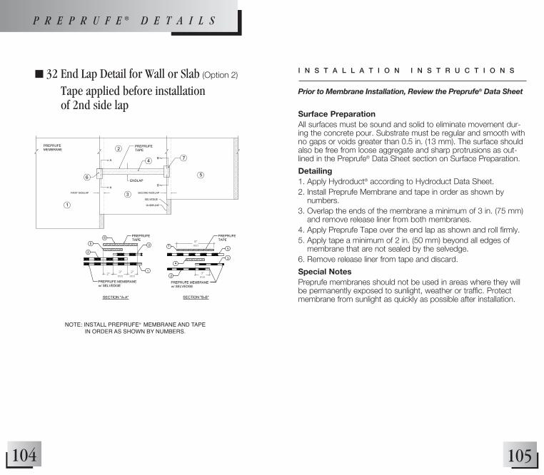
105104
n 32 End Lap Detail for Wall or Slab (Option 2)
Tape applied before installation of 2nd side lap
Surface PreparationAll surfaces must be sound and solid to eliminate movement dur-ing the concrete pour. Substrate must be regular and smooth with no gaps or voids greater than 0.5 in. (13 mm). The surface should also be free from loose aggregate and sharp protrusions as out-lined in the Preprufe® Data Sheet section on Surface Preparation.
Detailing1. Apply Hydroduct® according to Hydroduct Data Sheet.2. Install Preprufe Membrane and tape in order as shown by
numbers.3. Overlap the ends of the membrane a minimum of 3 in. (75 mm)
and remove release liner from both membranes.4. Apply Preprufe Tape over the end lap as shown and roll firmly. 5. Apply tape a minimum of 2 in. (50 mm) beyond all edges of
membrane that are not sealed by the selvedge.6. Remove release liner from tape and discard.
Special NotesPreprufe membranes should not be used in areas where they will be permanently exposed to sunlight, weather or traffic. Protect membrane from sunlight as quickly as possible after installation.
NOTE: INSTALL PREPRUFE® MEMBRANE AND TAPE IN ORDER AS SHOWN BY NUMBERS.
Prior to Membrane Installation, Review the Preprufe® Data Sheet
I N S T A L L A T I O N I N S T R U C T I O N S
P R E P R U F E ® D E T A I L S

107106
n 33 Inside Corner - Custom Formed
Surface PreparationAll surfaces must be sound and solid to eliminate movement dur-ing the concrete pour. Substrate must be regular and smooth with no gaps or voids greater than 0.5 in. (13 mm). The surface should also be free from loose aggregate and sharp protrusions as out-lined in the Preprufe® Data Sheet section on Surface Preparation.
Detailing1. Precut a square section of Preprufe membrane (minimum 12 in.
[300 mm] x 12 in. [300 mm]).2. Fold membrane as indicated on detail drawing, with release liner
on.3. Crease the fold with nominal hand pressure to ensure a close fit
to the substrate profile and avoid hollows.4. With the white coating facing towards the concrete, ensure
that the apex of the corner is covered and sealed with Preprufe Tape.
5. Remove release liner and roll tape firmly using steel or vinyl cylindrical or Vee roller.
6. Seal corner detail to Preprufe field membrane using Preprufe Tape and roll firmly.
7. Apply Hydroduct® according to Hydroduct Data Sheet.
Special NotesPreprufe membranes should not be used in areas where they will be permanently exposed to sunlight, weather or traffic. Protect membrane from sunlight as quickly as possible after installation.
Prior to Membrane Installation, Review the Preprufe® Data Sheet
I N S T A L L A T I O N I N S T R U C T I O N S
P R E P R U F E ® D E T A I L S
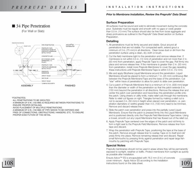
109108
n 34 Pipe Penetration (For Wall or Slab)
*FOOTNOTES:· ALL PENETRATIONS TO BE GROUTED.· A MINIMUM OF 6 IN. (150 MM) IS REQUIRED BETWEEN PENTRATIONS TO ENSURE PROPER DETAILING.
· AvOID PLACEMENT OF MULTIPLE PENETRATIONS.· A MINIMUM OF 6 IN. (150 MM) OF PIPE NEEDS TO BE EXPOSED AND FREE OF CONNECTIONS, OBSTRUCTIONS, HANGERS, ETC. TO ENSURE PROPER EXECTUTION OF THE DETAIL.
Surface PreparationAll surfaces must be sound and solid to eliminate movement during the concrete pour. Substrate must be regular and smooth with no gaps or voids greater than 0.5 in. (13 mm) The surface should also be free from loose aggregate and sharp protrusions as outlined in the Preprufe® Data Sheet section on Surface Preparation.
Detailing1. All penetrations must be firmly secured and stable. Grout around all
penetrations that are not stable. For compacted earth, extend grout a minimum of 3 in. (75 mm) in all directions. Clean loose dust or dirt from the penetration surface using a clean, dry cloth or brush.
2. Cut the field membrane tight to the penetration and remove release liner. If membrane is not within 0.5 in. (12 mm) of penetration and not more than 2 in. (50 mm) from penetration, apply Preprufe Tape to cover the gap. Roll firmly into place and remove release liner. If the membrane is greater than 2 in. (50 mm) from penetration, install more Preprufe Membrane to cover the gap repeating these instructions until Preprufe Membrane/Tape is within 0.5 in. (12 mm).
3. Mix and apply Bituthene Liquid Membrane around the penetration. Liquid Membrane should be placed to form a minimum 1 in. (25 mm) continuous fillet between the Preprufe Membrane/Tape and the base of the penetration. Cut “star” within trace of penetration to allow for patch to slide over penetration.
4. Cut a patch of Preprufe Membrane that is a minimum of 12 in. (300 mm) larger than the diameter or width of the penetration so that the patch extends 6 in. (150 mm) beyond the penetration in all directions. Remove the release liner and center the patch over penetration and trace/draw the penetration profile onto the patch. Using sheers or utility knife, make relief cuts through the membrane. Refer to relief cut figures on right. Triangles formed by making a relief cut is not to exceed 2 in. (50 mm) in height when placed over penetration, i.e. pen-etration diameters or widths greater than 4 in. (100 mm) need to be trimmed. Remove and discard release liner.
5. Slide the patch over penetration and press into the partially cured Liquid Membrane. Ensure that the patch is pressed firmly into the Liquid Membrane and is positioned directly onto the Preprufe Field Membrane/Tape below. Using a trowel, smooth out any Liquid Membrane that has flowed out of the relief cut.
6. Apply Preprufe Tape centered over the edges of the patch and roll firmly to form a tight seal to the Preprufe Field Membrane. Remove release liner from tape and discard.
7. Wrap the penetration with Preprufe Tape, positioning the tape at the base of the patch. Remove enough release liner to overlap Tape on to itself and roll/press firmly into place. Remove remaining release liner and discard. Repair small fishmouths by pressing firmly against penetration and repair large fish-mouths by patching with Preprufe Tape.
Special NotesPreprufe membranes should not be used in areas where they will be permanently exposed to sunlight, weather or traffic. Protect membrane from sunlight as quickly as possible after installation.Ensure Adcor™ ES is encapsulated with 76.2 mm (3 in.) of concrete cover minimum. Apply Adcor ES according to the installation instructions found on the data sheet.
Prior to Membrane Installation, Review the Preprufe® Data Sheet
I N S T A L L A T I O N I N S T R U C T I O N SP R E P R U F E ® D E T A I L S
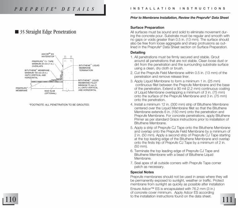
111110
n 35 Straight Edge Penetration
*FOOTNOTE: ALL PENETRATION TO BE GROUTED.
Surface PreparationAll surfaces must be sound and solid to eliminate movement dur-ing the concrete pour. Substrate must be regular and smooth with no gaps or voids greater than 0.5 in. (13 mm). The surface should also be free from loose aggregate and sharp protrusions as out-lined in the Preprufe® Data Sheet section on Surface Preparation.
Detailing1. All penetrations must be firmly secured and stable. Grout
around all penetrations that are not stable. Clean loose dust or dirt from the penetration and the surrounding substrate surface using a clean, dry cloth or brush.
2. Cut the Preprufe Field Membrane within 0.5 in. (13 mm) of the penetration and remove release liner.
3. Apply Liquid Membrane to form a minimum 1 in. (25 mm) continuous fillet between the Preprufe Membrane and the base of the penetration. Extend a 90 mil (2.2 mm) continuous coating of Liquid Membrane overlapping a minimum of 3 in. (75 mm) onto the surface of the Preprufe Membrane and 3 in. (75 mm) onto the penetration.
4. Install a minimum 12 in. (300 mm) strip of Bituthene Membrane centered over the Liquid Membrane fillet so that the Bituthene Membrane extends 6 in. (150 mm) onto the penetration and Preprufe Membrane. For concrete penetrations, apply Bituthene Primer as per standard Grace instructions prior to installation of Bituthene Membrane.
5. Apply a strip of Preprufe CJ Tape onto the Bituthene Membrane and overlap onto the Preprufe Field Membrane by a minimum of 2 in. (50 mm). Apply a second strip of Preprufe CJ Tape starting at the top leading edge of the Bituthene Membrane and overlap onto the firsts trip of Preprufe CJ Tape by a minimum of 2 in. (50 mm).
6. Terminate the top leading edge of Preprufe CJ Tape and Bituthene Membrane with a bead of Bituthene Liquid Membrane.
7. Seal apex of all outside corners with Preprufe Tape corner patch as necessary.
Special NotesPreprufe membranes should not be used in areas where they will be permanently exposed to sunlight, weather or traffic. Protect membrane from sunlight as quickly as possible after installationEnsure Adcor™ ES is encapsulated with 76.2 mm (3 in.) of concrete cover minimum. Apply Adcor ES according to the installation instructions found on the data sheet.
Prior to Membrane Installation, Review the Preprufe® Data Sheet
I N S T A L L A T I O N I N S T R U C T I O N SP R E P R U F E ® D E T A I L S
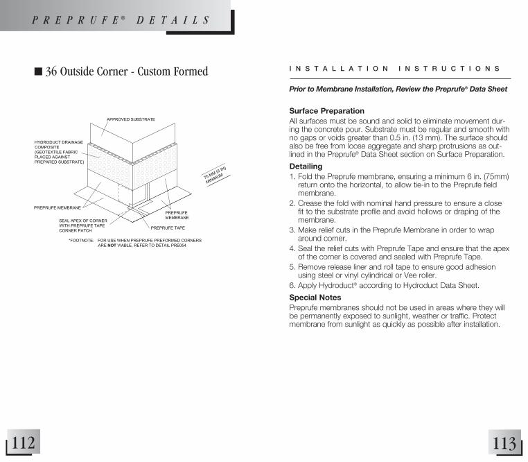
113112
n 36 Outside Corner - Custom Formed
Surface PreparationAll surfaces must be sound and solid to eliminate movement dur-ing the concrete pour. Substrate must be regular and smooth with no gaps or voids greater than 0.5 in. (13 mm). The surface should also be free from loose aggregate and sharp protrusions as out-lined in the Preprufe® Data Sheet section on Surface Preparation.
Detailing1. Fold the Preprufe membrane, ensuring a minimum 6 in. (75mm)
return onto the horizontal, to allow tie-in to the Preprufe field membrane.
2. Crease the fold with nominal hand pressure to ensure a close fit to the substrate profile and avoid hollows or draping of the membrane.
3. Make relief cuts in the Preprufe Membrane in order to wrap around corner.
4. Seal the relief cuts with Preprufe Tape and ensure that the apex of the corner is covered and sealed with Preprufe Tape.
5. Remove release liner and roll tape to ensure good adhesion using steel or vinyl cylindrical or Vee roller.
6. Apply Hydroduct® according to Hydroduct Data Sheet.
Special NotesPreprufe membranes should not be used in areas where they will be permanently exposed to sunlight, weather or traffic. Protect membrane from sunlight as quickly as possible after installation.
Prior to Membrane Installation, Review the Preprufe® Data Sheet
I N S T A L L A T I O N I N S T R U C T I O N S
P R E P R U F E ® D E T A I L S

115114
n 37 Column (Option 1)
Surface PreparationAll surfaces must be sound and solid to eliminate movement dur-ing the concrete pour. Substrate must be regular and smooth with no gaps or voids greater than 0.5 in. (13 mm). The surface should also be free from loose aggregate and sharp protrusions as out-lined in the Preprufe® Data Sheet section on Surface Preparation.
Detailing1. Place Preprufe membrane over the column footing and directly
under the column.2. Tie-in penetrations such as rebar and threaded rod that
penetrate the membrane should be sealed with Bituthene Liquid Membrane.
3. Cut the membrane tight to the penetration and ensure the penetration is free from rust, dirt, dust, etc.
4. If membrane is not within 0.5 in. (13 mm) of penetration, apply Preprufe Tape to cover the gap.
5. Mix and apply Bituthene Liquid Membrane around the penetration.
6. Bituthene Liquid Membrane should be placed to form a mini-mum 1 in. (25 mm) continuous fillet around the penetration at the point of penetration.
7. Bituthene Liquid Membrane should be applied as a 90 mil (2.2 mm) continuous coating overlapping a minimum of 3 in. (75 mm) onto the surface of the Preprufe Membrane.
8. Apply Hydroduct® according to Hydroduct Data Sheet.
Special NotesPreprufe membranes should not be used in areas where they will be permanently exposed to sunlight, weather or traffic. Protect membrane from sunlight as quickly as possible after installation.
Prior to Membrane Installation, Review the Preprufe® Data Sheet
I N S T A L L A T I O N I N S T R U C T I O N S
P R E P R U F E ® D E T A I L S

117116
n 38 Column (Option 2)
Surface PreparationAll surfaces must be sound and solid to eliminate movement dur-ing the concrete pour. Substrate must be regular and smooth with no gaps or voids greater than 0.5 in. (13 mm). The surface should also be free from loose aggregate and sharp protrusions as out-lined in the Preprufe® Data Sheet section on Surface Preparation.
Detailing1. Install the membrane following the vertical and horizontal
application instructions on the Preprufe data sheet found at graceconstruction.com.
2. Place the Preprufe membrane below the column footing before it is poured.
3. When placing the membrane it is important to leave sufficient length (typically 18 in. [300 mm]) of Preprufe 300R beyond the footing to allow for tie-in to the Preprufe membrane that will be laid to waterproof the general slab area.
4. Leave release liner on this extra length and protect it from damage until the tie-in details are completed.
5. Apply Hydroduct® according to Hydroduct Data Sheet.
Special NotesPreprufe membranes should not be used in areas where they will be permanently exposed to sunlight, weather or traffic. Protect membrane from sunlight as quickly as possible after installation.
Prior to Membrane Installation, Review the Preprufe® Data Sheet
I N S T A L L A T I O N I N S T R U C T I O N S
P R E P R U F E ® D E T A I L S

119118
n 39 Wall Termination for Elevated SlabSurface PreparationAll surfaces must be sound and solid to eliminate movement during the concrete pour. Substrate must be regular and smooth with no gaps or voids greater than 0.5 in. (13 mm). The surface should also be free from loose aggregate and sharp protrusions as outlined in the Preprufe® Data Sheet section on Surface Preparation.
Detailing1. Install Preprufe 300R Membrane over mud slab.2. For compacted earth, proper compaction is required. If the wall
area is too small to allow proper compaction, the base of the wall should be grouted solid. Areas to receive Bituthene Liquid Membrane MUST be grouted solid.
3. Apply Bituthene Liquid Membrane on the mud slab from the base of the wall to a minimum of 0.5 in. (13 mm) under where the leading edge of the Preprufe Membrane will terminate.
4. Install Preprufe 300R Membrane within 0.5 in. (13 mm) of all vertical and horizontal intersections.
5. Apply Liquid Membrane to form a minimum 1 in. (25 mm) continuous fillet between the Preprufe Membrane and the wall. Extend a 90 mil (2.2 mm) continuous coating of Liquid Membrane overlapping a minimum of 3 in. (75 mm) onto the sur-face of the Preprufe Membrane and 3 in. (75 mm) onto the wall.
6. Install a minimum 12 in. (300 mm) strip of Bituthene Membrane centered over the Liquid Membrane fillet so that the Bituthene Membrane extends 6 in. (150 mm) onto the wall and 6 in. (150 mm) onto the Preprufe Membrane. Apply Bituthene Primer as per standard Grace instructions prior to installation of Bituthene Membrane.
7. Apply a strip of Preprufe CJ Tape onto the Bituthene Membrane and overlap onto the Preprufe Field Membrane by a minimum of 2 in. (50 mm). Apply a second strip of Preprufe CJ Tape starting at the top leading edge of the Bituthene Membrane and overlap onto the firsts trip of Preprufe CJ Tape by a minimum of 2 in. (50 mm).
8. Terminate the top leading edge of Preprufe CJ Tape and Bituthene Membrane with a bead of Bituthene Liquid Membrane.
Special NotesPreprufe membranes should not be used in areas where they will be permanently exposed to sunlight, weather or traffic. Protect membrane from sunlight as quickly as possible after installation.Ensure Adcor™ ES is encapsulated with 76.2 mm (3 in.) of concrete cover minimum. Apply Adcor ES according to the installation instructions found on the data sheet.
*FOOTNOTES:· IF A MUDSLAB IS NOT USED, THE SUBSTRATE TO ACCEPT BITUTHENE LIQUID MEMBRANE MUST BE GROUTED SOILD TO PROvIDE AN ACCEPT-ABLE SUBSTRATE FOR THE LIQUID MEMBRANE.
· NOT INTENDED FOR HYDROSTATIC CONDITIONS.
Prior to Membrane Installation, Review the Preprufe® Data Sheet
I N S T A L L A T I O N I N S T R U C T I O N SP R E P R U F E ® D E T A I L S

121120
n 40 Wall Termination to Bituthene MembraneSurface PreparationAll surfaces must be sound and solid to eliminate movement dur-ing the concrete pour. Substrate must be regular and smooth with no gaps or voids greater than .05 in. (12 mm). The surface should also be free from loose aggregate and sharp protrusions as out-lined in the Preprufe® Data Sheet section on Surface Preparation. Ensure the surface of the Bituthene Membrane is protected during Preprufe installation.
Detailing1. Install Preprufe 300R Membrane over the prepared substrate
as outlined in the Preprufe Data Sheet found at graceconstruction.com.
2. For compacted earth, proper compaction is required. If the wall area is too small to allow proper compaction, the base of the wall should be grouted solid.
3. Install Preprufe 300R Membrane tight to all vertical and horizon-tal intersections.
4. Apply Bituthene Liquid Membrane to form a minimum 1 in. (25 mm) continuous fillet between the Preprufe membrane and the Bituthene membrane.
5. Starting a minimum of 4 in. (100 mm) from the edge of the Liquid Membrane fillet, apply Preprufe CJ Tape and extend it over the Liquid Membrane fillet and onto the Bituthene Membrane.
6. Apply a second strip of Preprufe CJ Tape starting at the top leading edge of the Bituthene Membrane and overlap onto the first strip of Preprufe CJ Tape by a minimum of 2 in. (50 mm).
7. Terminate the top leading edge of Preprufe CJ Tape and Bituthene Membrane with a bead of Bituthene Liquid Membrane.
8. Roll tape to ensure good adhesion using steel or vinyl cylindrical or Vee roller.
Special NotesPreprufe membranes should not be used in areas where they will be permanently exposed to sunlight, weather or traffic. Protect membrane from sunlight as quickly as possible after installation.Ensure Adcor™ ES is encapsulated with 76.2 mm (3 in.) of con-crete cover minimum. Apply Adcor ES according to the installa-tion instructions found on the data sheet.
Prior to Membrane Installation, Review the Preprufe® Data Sheet
I N S T A L L A T I O N I N S T R U C T I O N SP R E P R U F E ® D E T A I L S
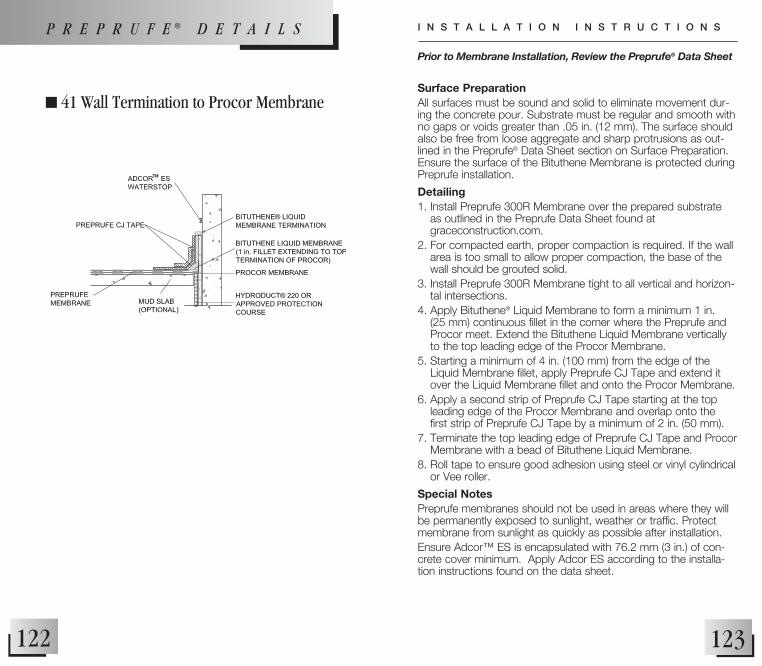
123122
n 41 Wall Termination to Procor MembraneSurface PreparationAll surfaces must be sound and solid to eliminate movement dur-ing the concrete pour. Substrate must be regular and smooth with no gaps or voids greater than .05 in. (12 mm). The surface should also be free from loose aggregate and sharp protrusions as out-lined in the Preprufe® Data Sheet section on Surface Preparation. Ensure the surface of the Bituthene Membrane is protected during Preprufe installation.
Detailing1. Install Preprufe 300R Membrane over the prepared substrate
as outlined in the Preprufe Data Sheet found at graceconstruction.com.
2. For compacted earth, proper compaction is required. If the wall area is too small to allow proper compaction, the base of the wall should be grouted solid.
3. Install Preprufe 300R Membrane tight to all vertical and horizon-tal intersections.
4. Apply Bituthene® Liquid Membrane to form a minimum 1 in. (25 mm) continuous fillet in the corner where the Preprufe and Procor meet. Extend the Bituthene Liquid Membrane vertically to the top leading edge of the Procor Membrane.
5. Starting a minimum of 4 in. (100 mm) from the edge of the Liquid Membrane fillet, apply Preprufe CJ Tape and extend it over the Liquid Membrane fillet and onto the Procor Membrane.
6. Apply a second strip of Preprufe CJ Tape starting at the top leading edge of the Procor Membrane and overlap onto the first strip of Preprufe CJ Tape by a minimum of 2 in. (50 mm).
7. Terminate the top leading edge of Preprufe CJ Tape and Procor Membrane with a bead of Bituthene Liquid Membrane.
8. Roll tape to ensure good adhesion using steel or vinyl cylindrical or Vee roller.
Special NotesPreprufe membranes should not be used in areas where they will be permanently exposed to sunlight, weather or traffic. Protect membrane from sunlight as quickly as possible after installation.Ensure Adcor™ ES is encapsulated with 76.2 mm (3 in.) of con-crete cover minimum. Apply Adcor ES according to the installa-tion instructions found on the data sheet.
Prior to Membrane Installation, Review the Preprufe® Data Sheet
I N S T A L L A T I O N I N S T R U C T I O N SP R E P R U F E ® D E T A I L S

125124
n 42 Joint
*NOTE: FOR JOINTS WITH EXPECTED MOvEMENT NOT TO EXCEED 0.5 IN. (13MM).
Surface PreparationAll surfaces must be sound and solid to eliminate movement dur-ing the concrete pour. Substrate must be regular and smooth with no gaps or voids greater than 0.5 in. (13 mm). The surface should also be free from loose aggregate and sharp protrusions as out-lined in the Preprufe® Data Sheet section on Surface Preparation.
Detailing1. Install the Preprufe membrane according to standard horizontal
and vertical application instructions on the Preprufe Data Sheet found at graceconstruction.com.
2. Preprufe CJ Tape should be applied to the surface of the Preprufe membrane and centered along the line of all concrete joints.
3. Remove release liner and roll tape to ensure good adhesion using steel or vinyl cylindrical or Vee roller.
4. Ensure any damaged tape or membrane is repaired after removal of formwork or bulkhead.
Special NotesPreprufe membranes should not be used in areas where they will be permanently exposed to sunlight, weather or traffic. Protect membrane from sunlight as quickly as possible after installation.
Prior to Membrane Installation, Review the Preprufe® Data Sheet
I N S T A L L A T I O N I N S T R U C T I O N S
P R E P R U F E ® D E T A I L S

127126
n 43 Grade Beam Pile Cap (Option 1)
Surface PreparationAll surfaces must be sound and solid to eliminate movement dur-ing the concrete pour. Substrate must be regular and smooth with no gaps or voids greater than 0.5 in. (13 mm). The surface should also be free from loose aggregate and sharp protrusions as out-lined in the Preprufe® Data Sheet section on Surface Preparation.
Detailing1. Install Preprufe Membrane over the prepared substrate in
accord with standard installation instructions.2. Preprufe Membrane is placed in the area formed for the pile cap
before the concrete is poured.3. When placing the membrane it is important to leave sufficient
length (typically 12 in. [300 mm]) of Preprufe beyond the pile cap area to allow for tie-in to the Preprufe Membrane that will be laid to waterproof the general slab area.
4. Cut membrane within 0.5 in. (13 mm) of each pile and complete detail around each pile in accordance with Detail PRE 035 or Detail PRE 034 depending on shape of pile.
Special NotesPreprufe membranes should not be used in areas where they will be permanently exposed to sunlight, weather or traffic. Protect membrane from sunlight as quickly as possible after installation.Piles must extend a minimum of 6 in. (150 mm) above the sub-strate to ensure proper execution of the detail.
Prior to Membrane Installation, Review the Preprufe® Data Sheet
I N S T A L L A T I O N I N S T R U C T I O N S
*NOTE: REFER TO PREPRUFE STRAIGHT EDGE PENETRATION DETAIL PRE 035 OR PREPRUFE PIPE PENETRATION DETAIL PRE 034
DEPENDING ON SHAPE OF PILE
P R E P R U F E ® D E T A I L S

129128
n 44 Grade Beam Pile Cap (Option 2)
Surface PreparationAll surfaces must be sound and solid to eliminate movement dur-ing the concrete pour. Substrate must be regular and smooth with no gaps or voids greater than 0.5 in. (13 mm). The surface should also be free from loose aggregate and sharp protrusions as out-lined in the Preprufe® Data Sheet section on Surface Preparation.
Detailing1. To allow for proper tie-in between Preprufe Field Membrane
and pile cap, a 6 in. (150 mm) ledge/shelf along the pile cap’s perimeter is required.
For Mud Slabs1. Clean loose dust or dirt from the pile cap and mud slab surface
using a clean, dry cloth or brush. 2. Apply a continuous 90 mil (2.2 mm) coating of Bituthene Liquid
Membrane or Procor over the top of the pile cap.3. Place a 1 in. (25 mm) bead of Liquid Membrane or Procor
around all penetrations at the point of penetration through the pile cap.
4. Prime along the edge of the mud slab a minimum of 6 in. (150 mm) from the edge of pile cap with a Bituthene Primer and allow to dry.
5. Align a 9 in. (225 mm) strip of Bituthene Membrane centered over the edge of the pile cap. Remove release liner and roll firmly onto the Liquid Membrane and primed mud slab.
6. Install Preprufe Membrane over the prepared substrate and terminate it 2 in. (50 mm) onto the pile cap.
7. Apply Preprufe Tape centered over the Preprufe Membrane termination. Remove the release liner and roll firmly.
8. Seal Bituthene Membrane and Preprufe Tape edge with a termination bead of Liquid Membrane.
(Continued on next page)
Prior to Membrane Installation, Review the Preprufe® Data Sheet
I N S T A L L A T I O N I N S T R U C T I O N S
P R E P R U F E ® D E T A I L S

131130
For Compacted Earth1. Apply a continuous 90 mil (2.2 mm) coating of
Bituthene Liquid Membrane or Procor over the top of the pile cap.
2. Place a 1 in. (25 mm) bead of Liquid Membrane or Procor around all penetrations at the point of penetra-tion through the pile cap.
3. Remove compacted earth away from sides of pile cap and remove formwork. Clean loose dust or dirt from the pile cap surface using a clean, dry cloth or brush.
4. Prime the sides of the pile cap a minimum of 6 in. (150 mm) from the top of pile cap with a Bituthene Primer and allow to dry.
5. Align a 9 in. (225 mm) strip of Bituthene Membrane centered over the outside edge (outside corner) of the pile cap. Remove release liner and roll firmly onto the Liquid Membrane and primed sides of pile cap.
6. Align a 12 in. (300 mm) strip of Bituthene Membrane centered over the outside edge (outside corner) of the pile cap.
7. Remove half of release liner by removing the RIPCORD® Split Release on Demand or by scoring release liner along the center of the strip.
8. Roll firmly onto the sides of pile cap with the 9 in. (225 mm) strip of Bituthene Membrane and the remaining primed pile cap.
9. Leave the other half of the 12 in. (300 mm) strip with the release liner still in tact in order to receive the Preprufe Membrane.
10. Replace earth/fill and compact per standard back-filling instructions being careful not to damage the Bituthene strip including the non-bonded portion.
11. Invert the Bituthene strip, and remove the remain-ing release liner to expose the adhesive portion of the Bituthene.
12. Install Preprufe Membrane over the prepared substrate and terminate it 2 in. (50 mm) onto the pile cap.
13. Roll firmly onto the inverted Bituthene strip.14. Apply Preprufe Tape centered over the Preprufe
Membrane termination. Remove the release liner and roll firmly.
15. Seal Bituthene Membrane and Preprufe Tape edge with a termination bead of Liquid Membrane.
16. Apply Hydroduct® according to Hydroduct Data Sheet.
Special NotesPreprufe membranes should not be used in areas where they will be permanently exposed to sunlight, weather or traffic. Protect membrane from sunlight as quickly as possible after installation.
P R E P R U F E ® D E T A I L S

133132
n 45 Tie Into Bituthene® Wall Waterproofing Plan View
Surface PreparationAll surfaces must be sound and solid to eliminate movement dur-ing the concrete pour. Substrate must be regular and smooth with no gaps or voids greater than 0.5 in. (13 mm). The surface should also be free from loose aggregate and sharp protrusions as out-lined in the Preprufe® Data Sheet section on Surface Preparation.
Detailing1. Install Preprufe 160R over the prepared vertical surface.2. Extend the Preprufe 160R Membrane 6 in. (150 mm) beyond
the end of the blind-side wall.3. As the foundation wall formwork is installed, fold the 12 in.
(300 mm) piece of Preprufe 160R Membrane to form a sharp corner.
4. Secure it to the inside face of the exterior form panel using Hydroduct Tape or small head fasteners located close to the outer edge of the membrane.
5. Once the wall is poured and cured for seven days, remove the formwork and install the post applied waterproofing according to the manufacturers standard installation procedures.
6. Apply Hydroduct® according to Hydroduct Data Sheet.
Special NotesPreprufe membranes should not be used in areas where they will be permanently exposed to sunlight, weather or traffic. Protect membrane from sunlight as quickly as possible after installation.Provide temporary protection for Preprufe at the tie-in location until the Bituthene tie-in is installed. The tie-in should be completed and backfilled as soon as possible.
Prior to Membrane Installation, Review the Preprufe® Data Sheet
I N S T A L L A T I O N I N S T R U C T I O N S
P R E P R U F E ® D E T A I L S
*NOTE: HYDRODUCT OR APPROvED PROTECTION COURSE NOT SHOWN FOR CLARITY OvER BITUTHENE.

135134
n 46 Preprufe Tie-Back Cover
Surface PreparationAll surfaces must be sound and solid to eliminate movement during the concrete pour. Substrate must be regular and smooth with no gaps or voids greater than 0.5 in. (13 mm). The surface should also be free from loose aggregate and sharp protrusions as outlined in the Preprufe® Data Sheet section on Surface Preparation.
Detailing1. Install Preprufe Membrane within 2 in. (50 mm) of tieback as per
standard installation instructions.2. Center the base over tieback head and secure base to soil
retention system using appropriate fasteners. Fasteners should have a low profile head.
3. Apply Preprufe Tape centered over the edge of the base flange and roll firmly to form a tight seal. Remove release liner and dis-card.
4. Position the membrane cover over the base taking care to ensure the cover flange sits flat onto the Preprufe Membrane.
5. Apply Preprufe Tape centered over the edge of the cover flange and roll firmly to form a tight seal. Remove release liner and dis-card.
6. All Preprufe Tape should overlap onto surfaces of tape, membrane, base, cover, etc. a minimum of 2 in. (50 mm).
7. Apply Hydroduct® according to Hydroduct Data Sheet.
Special NotesPreprufe membranes should not be used in areas where they will be permanently exposed to sunlight, weather or traffic. Protect membrane from sunlight as quickly as possible after installation.
Prior to Membrane Installation, Review the Preprufe® Data Sheet
I N S T A L L A T I O N I N S T R U C T I O N S
P R E P R U F E ® D E T A I L S
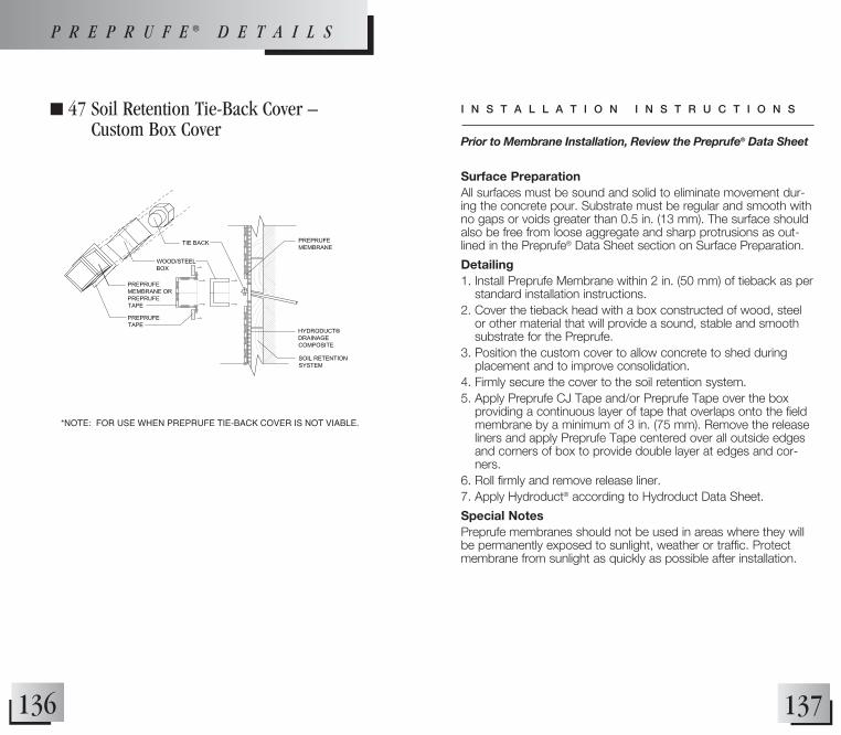
137136
n 47 Soil Retention Tie-Back Cover – Custom Box Cover
Surface PreparationAll surfaces must be sound and solid to eliminate movement dur-ing the concrete pour. Substrate must be regular and smooth with no gaps or voids greater than 0.5 in. (13 mm). The surface should also be free from loose aggregate and sharp protrusions as out-lined in the Preprufe® Data Sheet section on Surface Preparation.
Detailing1. Install Preprufe Membrane within 2 in. (50 mm) of tieback as per
standard installation instructions.2. Cover the tieback head with a box constructed of wood, steel
or other material that will provide a sound, stable and smooth substrate for the Preprufe.
3. Position the custom cover to allow concrete to shed during placement and to improve consolidation.
4. Firmly secure the cover to the soil retention system.5. Apply Preprufe CJ Tape and/or Preprufe Tape over the box
providing a continuous layer of tape that overlaps onto the field membrane by a minimum of 3 in. (75 mm). Remove the release liners and apply Preprufe Tape centered over all outside edges and corners of box to provide double layer at edges and cor-ners.
6. Roll firmly and remove release liner.7. Apply Hydroduct® according to Hydroduct Data Sheet.
Special NotesPreprufe membranes should not be used in areas where they will be permanently exposed to sunlight, weather or traffic. Protect membrane from sunlight as quickly as possible after installation.
*NOTE: FOR USE WHEN PREPRUFE TIE-BACK COvER IS NOT vIABLE.
Prior to Membrane Installation, Review the Preprufe® Data Sheet
I N S T A L L A T I O N I N S T R U C T I O N S
P R E P R U F E ® D E T A I L S

139138
n 48 Top Termination and End Lap
Surface PreparationAll surfaces must be sound and solid to eliminate movement dur-ing the concrete pour. Substrate must be regular and smooth with no gaps or voids greater than 0.5 in. (13 mm). The surface should also be free from loose aggregate and sharp protrusions as out-lined in the Preprufe® Data Sheet section on Surface Preparation.
Detailing1. Apply Preprufe field membrane according to standard
installation procedures.2. Apply termination bar to Preprufe membrane.3. Center Preprufe CJ Tape to cover termination bar and roll firmly.4. Protect top of termination of membrane from exposure.5. For end lap, overlap successive membrane rolls by 3 in.
(75 mm).6. Apply Preprufe Tape, centered over the lap.
(Refer to PRE 031 and PRE 032)7. Apply Hydroduct® according to Hydroduct Data Sheet.
Special NotesPreprufe membranes should not be used in areas where they will be permanently exposed to sunlight, weather or traffic. Protect membrane from sunlight as quickly as possible after installation.
Prior to Membrane Installation, Review the Preprufe® Data Sheet
I N S T A L L A T I O N I N S T R U C T I O N S
P R E P R U F E ® D E T A I L S

141140
n 49 Rebar, Dowel, and All-Thread Penetration
P R E P R U F E ® D E T A I L S
Surface PreparationAll surfaces must be sound and solid to eliminate movement dur-ing the concrete pour. Substrate must be regular and smooth with no gaps or voids greater than 0.5 in. (13 mm). The surface should also be free from loose aggregate and sharp protrusions as out-lined in the Preprufe® Data Sheet section on Surface Preparation.
Detailing1. All penetrations must be firmly secured and stable. Grout
around all penetrations that are not stable. Clean loose dust or dirt from the penetration and the surrounding substrate surface using a clean, dry cloth or brush.
2. Mix and apply Bituthene Liquid Membrane around the penetra-tion. Liquid Membrane should be placed to form a minimum 1 in. (25 mm) continuous fillet between the substrate and the base of the penetration.
3. Cut the field membrane tight to the penetration and remove release liner. If membrane is not within 0.5 in. (12 mm) of penetration and not more than 2 in. (50 mm) from penetration, apply Preprufe Tape to cover the gap. Roll firmly into place and remove release. If the membrane is greater than 2 in. (50 mm) from penetration, install more Preprufe Membrane to cover the gap repeating these instructions until Preprufe Membrane/Tape is within 0.5 in. (12 mm).
4. Position the field membrane snug to the penetration so that it is a maximum of 0.5 in. (12 mm) from the base of the penetration and press firmly into the partially cured Liquid Membrane.
5. Apply Liquid Membrane to form a minimum 1 in. (25 mm) continuous fillet between the Preprufe Membrane and the base of the penetration. Extend a 90 mil (2.2 mm) continuous coating of Liquid Membrane overlapping a minimum of 3 in. (75 mm) onto the surface of the Preprufe Membrane and 6 in. (150 mm) onto the penetration.
6. Wrap the penetration with Preprufe Tape, positioning the tape at the base of the penetration. Remove enough release liner to overlap tape on to itself and roll/press firmly into place. Remove remaining release liner and discard.
Special NotesPreprufe membranes should not be used in areas where they will be permanently exposed to sunlight, weather or traffic. Protect membrane from sunlight as quickly as possible after installation.Ensure Adcor™ ES is encapsulated with 76.2 mm (3 in.) of con-crete cover minimum. Apply Adcor ES according to the installa-tion instructions found on the data sheet.
Prior to Membrane Installation, Review the Preprufe® Data Sheet
I N S T A L L A T I O N I N S T R U C T I O N S
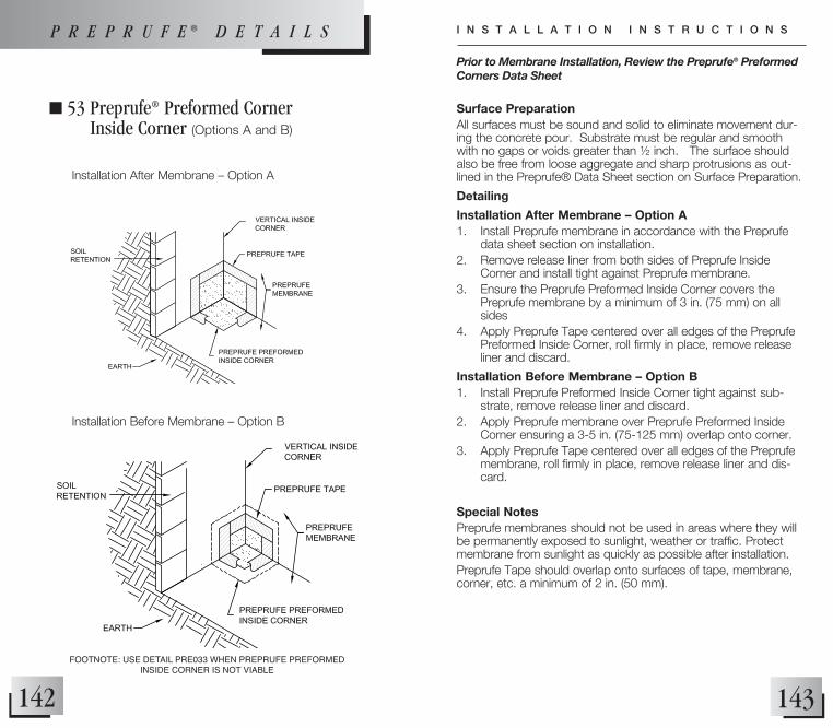
143142
n 53 Preprufe® Preformed Corner Inside Corner (Options A and B)
Surface PreparationAll surfaces must be sound and solid to eliminate movement dur-ing the concrete pour. Substrate must be regular and smooth with no gaps or voids greater than ½ inch. The surface should also be free from loose aggregate and sharp protrusions as out-lined in the Preprufe® Data Sheet section on Surface Preparation.
Detailing
Installation After Membrane – Option A1. Install Preprufe membrane in accordance with the Preprufe
data sheet section on installation.2. Remove release liner from both sides of Preprufe Inside
Corner and install tight against Preprufe membrane.3. Ensure the Preprufe Preformed Inside Corner covers the
Preprufe membrane by a minimum of 3 in. (75 mm) on all sides
4. Apply Preprufe Tape centered over all edges of the Preprufe Preformed Inside Corner, roll firmly in place, remove release liner and discard.
Installation Before Membrane – Option B1. Install Preprufe Preformed Inside Corner tight against sub-
strate, remove release liner and discard.2. Apply Preprufe membrane over Preprufe Preformed Inside
Corner ensuring a 3-5 in. (75-125 mm) overlap onto corner.3. Apply Preprufe Tape centered over all edges of the Preprufe
membrane, roll firmly in place, remove release liner and dis-card.
Special NotesPreprufe membranes should not be used in areas where they will be permanently exposed to sunlight, weather or traffic. Protect membrane from sunlight as quickly as possible after installation.Preprufe Tape should overlap onto surfaces of tape, membrane, corner, etc. a minimum of 2 in. (50 mm).
Prior to Membrane Installation, Review the Preprufe® Preformed Corners Data Sheet
I N S T A L L A T I O N I N S T R U C T I O N SP R E P R U F E ® D E T A I L S
Installation After Membrane – Option A
Installation Before Membrane – Option B
FOOTNOTE: USE DETAIL PRE033 WHEN PREPRUFE PREFORMED INSIDE CORNER IS NOT vIABLE

145144
n 54 Preprufe® Preformed Corner Outside Corner (Options A and B)
Surface PreparationAll surfaces must be sound and solid to eliminate movement dur-ing the concrete pour. Substrate must be regular and smooth with no gaps or voids greater than ½ inch. The surface should also be free from loose aggregate and sharp protrusions as out-lined in the Preprufe® Data Sheet section on Surface Preparation.
Detailing
Installation After Membrane – Option A1. Install Preprufe membrane in accordance with the Preprufe
data sheet section on installation.2. Remove release liner from both sides of Preprufe Outside
Corner and install tight against Preprufe membrane.3. Ensure the Preprufe Preformed Outside Corner covers the
Preprufe membrane by a minimum of 3 in. (75 mm) on all sides
4. Apply Preprufe Tape centered over all edges of the Preprufe Preformed Outside Corner, roll firmly in place, remove release liner and discard.
Installation Before Membrane – Option B1. Install Preprufe Preformed Outside Corner tight against sub-
strate, remove release liner and discard.2. Apply Preprufe membrane over Preprufe Preformed Outside
Corner ensuring a 3-5 in. (75-125 mm) overlap onto corner.3. Apply Preprufe Tape centered over all edges of the Preprufe
membrane, roll firmly in place, remove release liner and dis-card.
Special NotesPreprufe membranes should not be used in areas where they will be permanently exposed to sunlight, weather or traffic. Protect membrane from sunlight as quickly as possible after installation.Preprufe Tape should overlap onto surfaces of tape, membrane, corner, etc. a minimum of 2 in. (50 mm).
Prior to Membrane Installation, Review the Preprufe® Preformed Corners Data Sheet
I N S T A L L A T I O N I N S T R U C T I O N SP R E P R U F E ® D E T A I L S
Installation After Membrane – Option A
Installation Before Membrane – Option B
FOOTNOTE: USE DETAIL PRE036 WHEN PREPRUFE PREFORMED OUTSIDE CORNER IS NOT vIABLE

147146
n 55 Preprufe® Preformed Corner Inside Cap (Options A and B)
Surface PreparationAll surfaces must be sound and solid to eliminate movement dur-ing the concrete pour. Substrate must be regular and smooth with no gaps or voids greater than ½ inch. The surface should also be free from loose aggregate and sharp protrusions as out-lined in the Preprufe® Data Sheet section on Surface Preparation.
Detailing
Installation After Membrane – Option A1. Install Preprufe membrane in accordance with the Preprufe
data sheet section on installation.2. Remove release liner from both sides of Preprufe Inside Cap
and install tight against Preprufe membrane.3. Ensure the Preprufe Preformed Inside Cap covers the
Preprufe membrane by a minimum of 3 in. (75 mm) on all sides
4. Apply Preprufe Tape centered over all edges of the Preprufe Preformed Inside Cap, roll firmly in place, remove release liner and discard.
Installation Before Membrane – Option B1. Install Preprufe Preformed Inside Cap tight against substrate,
remove release liner and discard.2. Apply Preprufe membrane over Preprufe Preformed Inside
Cap ensuring a 3-5 in. (75-125 mm) overlap onto cap.3. Apply Preprufe Tape centered over all edges of the Preprufe
membrane, roll firmly in place, remove release liner and dis-card.
Special NotesPreprufe membranes should not be used in areas where they will be permanently exposed to sunlight, weather or traffic. Protect membrane from sunlight as quickly as possible after installation.Preprufe Tape should overlap onto surfaces of tape, membrane, cap, etc. a minimum of 2 in. (50 mm).
Prior to Membrane Installation, Review the Preprufe® Preformed Corners Data Sheet
I N S T A L L A T I O N I N S T R U C T I O N SP R E P R U F E ® D E T A I L S
Installation After Membrane – Option A
Installation Before Membrane – Option B

149148
n 56 Preprufe® Preformed Corner Outside Cap (Options A and B)
Surface PreparationAll surfaces must be sound and solid to eliminate movement dur-ing the concrete pour. Substrate must be regular and smooth with no gaps or voids greater than ½ inch. The surface should also be free from loose aggregate and sharp protrusions as out-lined in the Preprufe® Data Sheet section on Surface Preparation.
Detailing
Installation After Membrane – Option A1. Install Preprufe membrane in accordance with the Preprufe
data sheet section on installation.2. Remove release liner from both sides of Preprufe Outside Cap
and install tight against Preprufe membrane.3. Ensure the Preprufe Preformed Outside Cap covers the
Preprufe membrane by a minimum of 3 in. (75 mm) on all sides
4. Apply Preprufe Tape centered over all edges of the Preprufe Preformed Outside Cap, roll firmly in place, remove release liner and discard.
Installation Before Membrane – Option B1. Install Preprufe Preformed Outside Cap tight against sub-
strate, remove release liner and discard.2. Apply Preprufe membrane over Preprufe Preformed Outside
Cap ensuring a 3-5 in. (75-125 mm) overlap onto corner.3. Apply Preprufe Tape centered over all edges of the Preprufe
membrane, roll firmly in place, remove release liner and dis-card.
Special NotesPreprufe membranes should not be used in areas where they will be permanently exposed to sunlight, weather or traffic. Protect membrane from sunlight as quickly as possible after installation.Preprufe Tape should overlap onto surfaces of tape, membrane, cap, etc. a minimum of 2 in. (50 mm).
Prior to Membrane Installation, Review the Preprufe® Preformed Corners Data Sheet
I N S T A L L A T I O N I N S T R U C T I O N SP R E P R U F E ® D E T A I L S
Installation After Membrane – Option A
Installation Before Membrane – Option B
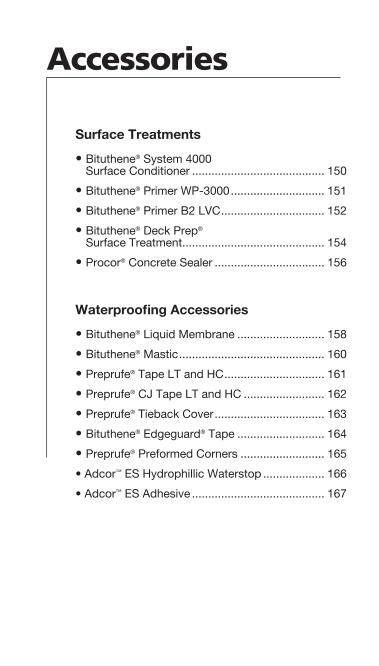
Accessories
Surface Treatments
• Bituthene® System 4000 Surface Conditioner ......................................... 150
• Bituthene® Primer WP-3000 ............................. 151
• Bituthene® Primer B2 LVC ................................ 152
• Bituthene® Deck Prep® Surface Treatment ............................................ 154
• Procor® Concrete Sealer .................................. 156
Waterproofing Accessories
• Bituthene® Liquid Membrane ........................... 158
• Bituthene® Mastic ............................................. 160
• Preprufe® Tape LT and HC ............................... 161
• Preprufe® CJ Tape LT and HC ......................... 162
• Preprufe® Tieback Cover .................................. 163
• Bituthene® Edgeguard® Tape ........................... 164
• Preprufe® Preformed Corners .......................... 165
• Adcor™ ES Hydrophillic Waterstop ................... 166
• Adcor™ ES Adhesive ......................................... 167
151150
UseBituthene® Primer WP-3000 is used to prime all structural concrete, masonry or wood surfaces on which Bituthene membranes will be applied.
Safety, Storage and Handling Instructions• Bituthene Primer WP-3000 is
nonflammable. • Store product in temperatures
above freezing 32°F (0°C). • Read product label and the
Material Safety Data Sheet before use.
Application• Bituthene Primer WP-3000 is
packaged ready to use. • Do not dilute with water or
solvent. • For best results, use a pump
type air sprayer with fan tip nozzle, like the Bituthene System 4000 Surface Conditioner Sprayer, to apply the primer.
• Apply Bituthene Primer WP-3000 to clean, dry, frost-free surfaces at a coverage rate of 500-600 ft2/gal (12-15 m2/L).
• Primer should not be applied so heavily that it puddles or runs.
• Back roll over all applied areas. • Allow primer to dry one hour or
until concrete returns to original color.
• In general, priming should be limited to what can be covered within 24 hours.
• Do not prime polyethylene surfaces.
• Before primer dries, tools should be cleaned with water.
• After primer dries, tools should be cleaned with mineral spirits. Mineral spirits is a combustible liquid which should be used only in accordance with manufacturer’s safety recommendations.
• Do not use solvents to clean hands or skin.
Bituthene® Primer WP-3000
UseBituthene® System 4000 Surface Conditioner is used to condi-tion all structural concrete, masonry or wood surfaces on which Bituthene System 4000 Waterproofing Membrane will be applied.
Safety, Storage and Handling Information• Bituthene System 4000
Surface Conditioner is nonflammable.
• Bituthene System 4000 Surface Conditioner has a freezing point of 14°F (-10°C) as packaged.
• Read product label and the Material Safety Data Sheet before use.
• Stable up to 5 freeze-thaw cycles.
Application• Bituthene System 4000 Surface
Conditioner is ready to use and can be applied by spray or roller.
• For best results, use a pump- type air sprayer with fan tip nozzle, like the Bituthene System 4000 Surface Conditioner Sprayer, to apply the surface conditioner.
• Apply Bituthene System 4000 Surface Conditioner to clean, dry, frost-free surfaces at a coverage rate of 300 ft2/gal (7.4 m2/L).
• Surface Conditioner should not be applied so heavily that it puddles or runs.
• Back roll over all applied areas. • Allow Bituthene System 4000
Surface Conditioner to dry one hour or until substrate returns to its original color.
• Bituthene System 4000 Surface Conditioner is clear when dry and may be slightly tacky. In general, conditioning should be limited to what can be covered within 24 hours.
• Do not prime polyethylene surfaces.
• Before Surface Conditioner dries, tools should be cleaned with water.
• After surface conditioner dries, tools should be cleaned with mineral spirits. Mineral spirits is a combustible liquid which should be used only in accordance with manufacturer’s recommendations.
• Do not use solvents to clean hands or skin.
• Do not dilute with water or solvent.
S U R F A C E T R E A T M E N T S
Bituthene® System 4000 Surface Conditioner

153152
UseBituthene® Primer B2 LVC is used to prime “green” con-crete, damp concrete, masonry or wood surfaces on which Bituthene waterproofing membranes will be applied.
Safety, Storage and Handling Information• Bituthene Primer B2 LVC
vapors are flammable. • Read product label and
Material Safety Data Sheet before use.
Application• Bituthene Primer B2 LVC may
be applied by roller or brush. Use a heavy nap roller made of natural material, such as lamb’s wool.
• Apply it to clean dirt-free, frost-free surfaces at a coverage rate of 325-425 ft2/gal (8-10.5 m2/L).
• Do not apply to frozen concrete or to areas with standing or visible water.
• Do not use during wet weather.
• Allow Bituthene Primer B2 LVC to dry one hour or until tack-free.
• Deep puddles of primer should be avoided as this will lengthen drying time.
• Back roll over all applied areas.• Avoid pouring primer directly
onto a horizontal substrate.• In general, priming should
be limited to an area that can be covered with Bituthene water-proofing membrane within 24 hours.
• Although it may be used on green concrete and damp surfaces, moisture may become trapped under the Bituthene waterproofing membrane. Therefore, cover the membrane as soon as possible to minimize blistering.
• If blistering occurs, allow membrane to cool and re-roll with heavy roller.
• Blisters over 4 in. (100 mm) in diameter should be cut and patched.
Bituthene® Primer B2 LVC
S U R F A C E T R E A T M E N T S
• Do not prime polyethylene surfaces.
• Clean tools with mineral spirits at the end of each day. Mineral spirits is a combustible liquid and should be used only in accordance with the manufacturer’s safety recommendations.
• Do not use solvents to clean hands or skin.

155154
Bituthene® Deck Prep® Surface Treatment
UseBituthene® Deck Prep® is ideally suited as a:• Leveling agent for rough
concrete decks for new and rehab construction
• Non-structural repair material for defects in concrete decks for new and rehab construction
• Temporary waterproofing layer• Primer layer for Bituthene
waterproofing membranes
Safety, Storage and Handling Information• Read product label and
Material Safety Data Sheet before use.
Compatibility• Bituthene Deck Prep is com-
pletely compatible with all other Bituthene products and with existing asphalt or coal tar-based waterproofing materials.
• It is also compatible with cured silicone and polyurethane seal-ants.
• It is not compatible with creosote, pentachlorophenol, linseed oil or polysulfide-based sealants.
Application• Substrate surfaces must be
completely dry and free from dirt, grease, oil, dust or other debris.
• Bituthene Deck Prep may be applied at temperatures of 25°F (-4°C) or above.
• For applications below 40°F (5°C), store in a warm place prior to use for best results.
• Do not apply if wet weather is expected within 4 hours of application.
• Add the entire contents of the Part B container to Part A and mix for 3 to 5 minutes until uniform.
• A low speed (150 rpm) mechanical mixer with flat par-allel blades is required.
• Once mixed, Bituthene Deck Prep should be poured directly onto the deck and spread with a squeegee or a trowel.
• Apply Bituthene Deck Prep within one hour after mixing.
• Bituthene Deck Prep should be applied in sufficient thickness to smooth all rough areas and fill all voids.
• Apply material in thicknesses not to exceed 1/2 in. (13 mm) per coat. Bituthene Deck Prep will adhere to dry, unprimed concrete.
• The product will support light foot traffic after an overnight cure. For interior applications, it may remain tacky even after fully cured.
• Apply Bituthene waterproofing membranes directly to cured Bituthene Deck Prep. No priming or conditioning is necessary.
• Clean tools and equipment with mineral spirits before the product has cured. Mineral spirits is a combustible liquid and should be used only in accordance with the manufacturer’s safety recommendations.
• Do not use solvents to clean hands or skin.
S U R F A C E T R E A T M E N T S
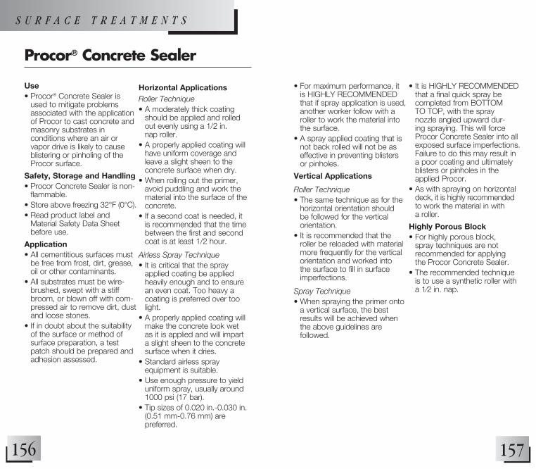
157156
Use• Procor® Concrete Sealer is
used to mitigate problems associated with the application of Procor to cast concrete and masonry substrates in conditions where an air or vapor drive is likely to cause blistering or pinholing of the Procor surface.
Safety, Storage and Handling• Procor Concrete Sealer is non-
flammable. • Store above freezing 32°F (0°C).• Read product label and
Material Safety Data Sheet before use.
Application• All cementitious surfaces must
be free from frost, dirt, grease, oil or other contaminants.
• All substrates must be wire-brushed, swept with a stiff broom, or blown off with com-pressed air to remove dirt, dust and loose stones.
• If in doubt about the suitability of the surface or method of surface preparation, a test patch should be prepared and adhesion assessed.
Horizontal ApplicationsRoller Technique• A moderately thick coating
should be applied and rolled out evenly using a 1/2 in. nap roller.
• A properly applied coating will have uniform coverage and leave a slight sheen to the concrete surface when dry.
• When rolling out the primer, avoid puddling and work the material into the surface of the concrete.
• If a second coat is needed, it is recommended that the time between the first and second coat is at least 1/2 hour.
Airless Spray Technique• It is critical that the spray
applied coating be applied heavily enough and to ensure an even coat. Too heavy a coating is preferred over too light.
• A properly applied coating will make the concrete look wet as it is applied and will impart a slight sheen to the concrete surface when it dries.
• Standard airless spray equipment is suitable.
• Use enough pressure to yield uniform spray, usually around 1000 psi (17 bar).
• Tip sizes of 0.020 in.-0.030 in. (0.51 mm-0.76 mm) are preferred.
Procor® Concrete Sealer
• For maximum performance, it is HIGHLY RECOMMENDED that if spray application is used, another worker follow with a roller to work the material into the surface.
• A spray applied coating that is not back rolled will not be as effective in preventing blisters or pinholes.
Vertical Applications
Roller Technique• The same technique as for the
horizontal orientation should be followed for the vertical orientation.
• It is recommended that the roller be reloaded with material more frequently for the vertical orientation and worked into the surface to fill in surface imperfections.
Spray Technique• When spraying the primer onto
a vertical surface, the best results will be achieved when the above guidelines are followed.
• It is HIGHLY RECOMMENDED that a final quick spray be completed from BOTTOM TO TOP, with the spray nozzle angled upward dur-ing spraying. This will force Procor Concrete Sealer into all exposed surface imperfections. Failure to do this may result in a poor coating and ultimately blisters or pinholes in the applied Procor.
• As with spraying on horizontal deck, it is highly recommended to work the material in with a roller.
Highly Porous Block• For highly porous block,
spray techniques are not recommended for applying the Procor Concrete Sealer.
• The recommended technique is to use a synthetic roller with a 1⁄2 in. nap.
S U R F A C E T R E A T M E N T S

159158
Use• The two parts of Bituthene®
Liquid Membrane are mixed on site and trowelled to provide a simple and quick waterproof-ing detailing aid in conjunc-tion with Bituthene, Preprufe® and Procor® systems. Liquid Membrane is ideally suited for the following uses:
• Fillet material at inside corners• Reinforcement material at
inside corners• Flashing material around
drains, protrusions, curbs and parapets
• Sealing material at terminations• Repair material for defects on
concrete surfaces• Flashing material at corners
Compatibility• Liquid Membrane is completely
compatible with Bituthene, Preprufe and Procor and with existing asphalt or coal tar-based waterproofing materials.
• It is also compatible with cured silicone and polyurethane seal-ants.
• It is not compatible with creosote, pentachlorophenol, linseed oil or polysulfide-based sealants.
Safety, Storage and Handling Information• Read product label and
Material Safety Data Sheet before use.
Application Procedures• All surfaces must be dry and
free from dirt, grease, oil, dust or other contaminants.
• Bituthene Liquid Membrane may be applied at tempera-tures of 25°F (-4°C) or above.
• Below 40°F (5°C), store in a warm place before application.
• Add the entire contents of the Part B container to Part A and mix for 3 to 5 minutes until uniform.
• A low speed (150 rpm) mechanical mixer with flat paddle blades is required. Take care to scrape material from the side and bottom of the container to assure thor-ough mixing. Do not apply any material if streaks can be seen due to insufficient mixing.
• Once mixed, apply immediately. Pot life varies with temperature.
• The material will cure to a very flexible rubber-like material.
W A T E R P R O O F I N G A C C E S S O R I E S
Bituthene® Liquid Membrane
• Liquid Membrane must be applied at a minimum thickness of 90 mils (2.3 mm) unless otherwise noted on details.
• In fillet applications, the face of the fillet should be a minimum of 3⁄4 in. (20 mm).
• In corner flashing application details, it should extend 6 in. (150 mm) in each direction from the corner.
• Liquid Membrane will adhere to primed or unprimed concrete.
• Liquid Membrane should be allowed to cure at least 24 hours before flood testing.
• Clean tools and equipment with mineral spirits before the material has cured. Mineral spirits is a combustible liquid and should be used only in accordance with the manufacturer’s safety recommendations.
• Do not use solvents to clean hands or skin.

161160
Use• Preprufe® Tape is used in detail
areas including end laps, penetrations and various tie-ins.
• It is also used to patch damaged areas in the Preprufe membranes.
Application Procedures• Use Preprufe Tape LT when
ambient temperatures are between 25° to 86°F (-4° to +30°C).
• Use Preprufe Tape HC in hot climates.
• Wipe Preprufe membranes clean to remove any dirt, dust or moisture.
• Prepare the surface of penetrations or protrusions with a wire brush to remove dirt, dust, rust and loose particles and wipe clean.
• Unroll the tape and adhere the exposed pressure sensitive adhesive surface to the membrane or penetration.
• The protective coating surface of the tape should face toward the concrete to be cast.
• Use heavy hand pressure or a hand roller to maximize adhesion.
• Remove the release liner immediately.
• Seal all T-joints with a vee roller or use the edge of a seam roller.
• Cast concrete within 56 days (42 days in hot climates) of application of the tape.
• For shotcrete placement, contact your local Grace sales representative.
Preprufe® Tape LT and HC
Use• Bituthene® Mastic is designed
to seal terminations, edges of patches, and overlaps in detail areas for Bituthene Waterproofing Membranes. On vertical applications, Bituthene Mastic must be applied to both the top and bottom terminations.
Safety, Storage and Handling Information• Bituthene Mastic vapor is
combustible. • Read product label and
Material Safety Data Sheet before use.
Application Procedures• Apply Bituthene Mastic either
with a caulking gun or trowel. • If applied with a caulking gun,
level the bead with a trowel to about 1/8 in. (3 mm) thickness and a 1/2 in. (13 mm) to 1 in. (25 mm) width.
• When applied as a temporary cutoff, trowel Bituthene Mastic to 95 mils (1.5 mm) thickness.
• Bituthene waterproofing mem-brane may be placed over the thin cutoff the next day.
• On the bottom edge of vertical applications, the mastic should be troweled upward.
• Bituthene Mastic should be used liberally at membrane terminations.
• Clean tools with mineral spirits at the end of each day. Mineral spirits is a combustible liquid and should be used only in accordance with the manufacturer’s safety recommendations.
• Do not use solvents to clean hands or skin.
Bituthene® Mastic
W A T E R P R O O F I N G A C C E S S O R I E S
163162
Use• Preprufe® Tieback Covers are
used to maintain waterproofing integrity at soil retention heads.
• Can be used with cable and rod type tieback heads.
Application Procedures• Install Preprufe field membrane
within 2 in. of tieback, on all sides.
• Center base over tieback and secure base directly to soil retention system using low profile head fasteners.
• Apply Preprufe Tape centered over the edge of the base flange and roll firmly to form a tight seal. Remove release liner and discard.
• Position the cover over the base, taking care to ensure the cover flange sits flat onto the Preprufe Membrane.
• Apply Preprufe Tape centered over the edge of the cover flange and roll firmly to form a tight seal. Remover release liner and discard.
• Preprufe Tape should overlap onto surfaces of tape, membrane, base, and cover a minimum of 2 in. (50 mm).
• For shotcrete placement, contact your local Grace sales representative.
Preprufe® Tieback Cover
Use• Preprufe® CJ Tape is used in
detail areas including along the line of all concrete joints.
• It is also used to patch damaged areas in the Preprufe Membranes.
Application Procedures• Use Preprufe CJ Tape LT
when ambient temperatures are between 25° to 86°F (-4° to +30°C).
• Use Preprufe CJ Tape HC in hot climates.
• Wipe Preprufe membranes clean to remove any dirt, dust or moisture.
• Clean the surface of penetra-tions or protrusions with a wire brush to remove dirt, dust, rust and loose particles.
• Unroll the tape and adhere the exposed pressure sensitive adhesive surface to the membrane or penetration.
• The protective coating surface of the tape should face toward the concrete to be cast.
• Use heavy hand pressure or a hand roller to maximize adhesion.
• Remove the release liner immediately.
• Seal all T-joints with a Vee roller or use the edge of a seam roller.
• Cast concrete within 56 days (42 days in hot climates) of application of the tape.
• For shotcrete placement, contact your local Grace sales representative.
Preprufe® CJ Tape LT and HC
W A T E R P R O O F I N G A C C E S S O R I E S

165164
Use• Bituthene® Edgeguard® Tape is
recommended for use over the Bituthene and Preprufe edges to protect the adhesive from prolonged exposure to hydro-carbon contaminated soil.
Application Procedures• On vertical and horizontal
applications, place a continu-ous strip of tape centered on all membrane side and end lap edges.
• In cooler temperatures, gently heat tape to enhance adhesion characteristics.
• Roll tape application with hand roller to maximize adhesion.
• Inspect application thoroughly, patch fishmouths with additional strips of tape as necessary to provide a tight seal.
Bituthene® Edgeguard® Tape
W A T E R P R O O F I N G A C C E S S O R I E S
Preprufe® Preformed Corners
Use•The Preprufe® Preformed Corners are prefabricated cor-ners specially designed to main-tain the waterproofing integrity at the inside and outside corners of a building. The Preprufe Preformed Corners utilize a pre-formed core covered with the proven Preprufe Advanced Bond Technology ensuring continuity of the Preprufe system.The Preprufe Preformed Corners are available in two configura-tions to accommodate most common installation needs and building designs. With the Preprufe Advanced Bond Technology on both sides of the core, each preformed corner can be used in two different details. The Preprufe Preformed Inside Corner is designed to also be used as an outside cap. The Preprufe Preformed Outside Corner is designed to also be used as an inside cap. Application Procedures Option A: Installation of Preprufe Preformed Corner after Preprufe membrane• Remove release liner from both
sides of Preprufe Preformed Corner and install tight against Preprufe membrane.
• Ensure the Preprufe Preformed Corner covers the Preprufe membrane by a minimum of 3 in. (75 mm) on all sides.
• Apply Preprufe Tape centered along all edges of the Preprufe Preformed Corner. Remove and discard release liner, roll firmly in place.
• Preprufe Tape should overlap onto surfaces of tape, mem-brane, corner, etc. a minimum of 2 in. (50 mm).
Option B: Installation of corner prior to Preprufe membrane• Install Preprufe Preformed
Corner tightly against sub-strate, remove release liner and discard.
• Apply Preprufe membrane over Preprufe Preformed Corner ensuring a 3–5 in. (75–125 mm) overlap onto corner.
• Apply Preprufe Tape centered along the edge of the Preprufe membrane and onto the corner. Remove and discard release liner, roll firmly in place.
• Preprufe Tape should overlap onto surfaces of tape, mem-brane, corner, etc. a minimum of 2 in. (50 mm).

167166
W A T E R P R O O F I N G A C C E S S O R I E S
Adcor™ ES Hydrophillic Waterstop
Use• Grace Adcor™ ES is a specially
engineered, swellable, con-formable synthetic waterstop strip that expands when in contact with water. The engi-neered swell design of Adcor ES minimizes the potential for concrete spalling and cracking versus traditional hydrophilic waterstops. When fully encap-sulated by poured concrete, the expansive forces form a seal against concrete faces. The seal resists hydrostatic pressure, stopping water from entering sub-structures. Adcor ES is a unique product that has been specifically developed to provide better performance than bentonite or conventional swellable rubber waterstops.
Application Procedures• Concrete surfaces must be
clean and Free of all contami-nants. Remove all debris and loose concrete.
• On irregular surfaces apply a ½” (12 mm) bead of Adcor ES Adhesive as bedding for Adcor ES.
• Secure Adcor ES using masonry nails 1 1/2-2 in. (40 mm-50 mm) long with
a Washer ¾ in. (20 mm) in diameter. Hilti EM6-20-12 FP8 shot fired fixings with ¼ in. (6 mm) nuts and ¾ in. wide (20 mm) diameter washers may also be used. Fixings should be spaced at a maximum of 12 in. (300 mm) centers with a minimum spacing that ensures proper contact to substrate
• For pipe penetrations, Adcor ES adhesive must be applied to dry substrates only. Apply by brush to the substrate. Wait until surface is dry to touch, and then press Adcor ES firmly into place.
• Adcor ES joints should overlap a Minimum of 4 in. (100 mm), ensuring full contact between jointed pieces.
• Adcor ES can be bent around corners, however, on com-plex geometry, use Adcor ES Adhesive to fill any gaps.
• Any damaged sections should be removed and repaired with a new section of Adcor ES.
• Keep Adcor ES dry prior to pouring concrete. Adcor™ ES Adhesive
Adcor™ ES Adhesive
Use• Adcor™ ES Adhesive is
designed for securing Adcor™ ES to concrete, steel and plas-tic substrates supplied in 29 fl oz (0.85L) tubes.
Safety, Storage and Handling Information• Read product label and
Material Safety Data Sheet before use.
Application Procedures• Apply a ½ in. (12 mm) bead of
Adcor ES Adhesive as bedding for Adcor ES.
• For pipe penetrations, Adcor ES adhesive must be applied to dry substrates only. Apply by brush to the substrate. Wait until surface is dry to touch, and then press Adcor ES firmly into place.
• Approximate coverage rate for Adcor ES Adhesive is 60 linear ft (18.3 m)/tube ½ in. wide bead on smooth pipe or smooth concrete. • Approximate coverage rate for Adcor ES Adhesive is 30 linear ft (9.1 m)/tube on porous con-crete or irregular surfaces (e.g. along keyway).

N O T E S

169168
168 ✔ ✔
174 ✔ ✔
178 ✔
182 ✔ ✔
184 ✔ ✔
185 ✔
186 ✔ ✔
188 ✔ ✔
190 ✔
194 ✔
198 ✔
204 ✔
206 ✔
210 ✔
214 ✔
216 ✔218 ✔
220 ✔
222 ✔224 ✔
226 ✔
228 ✔
230 ✔ ✔
232 ✔
234 ✔
236 ✔
240 ✔ ✔
242 ✔ ✔
244 ✔ ✔
246 ✔ ✔ ✔
248 ✔
250 ✔ ✔ ✔
252 ✔
254 ✔ ✔ ✔ ✔ 256 ✔
258 ✔ ✔ ✔ ✔
Page No. Bituthene Preprufe Procor HydroductT E C H N I C A L L E T T E r s
1 Concrete and Concrete Surfaces 2 Inspection and Repair of Concrete 3 Bituthene® Performance Testing 4 Chemical Resistance 5 Curing Compounds and Form Release Agents 6 UL Approval Class A Fire Rating 7 Waterproofing Concrete Masonry (CMU) Walls 8 Waterproofing Plywood Substrates 9 Retrofit Waterproofing10 Chemical Compatibility of Bituthene® and Perm-A-Barrier®
Membranes with Other Materials11 Expansion Joint in Concrete Construction12 Bituthene Longevity13 Forming Systems for Use with Preprufe® 160R Membrane14 Minimizing Concrete Shrinkage and Curling15 Rebar Chairs on Preprufe® 300R Membrane16 Preprufe® Waterproofing Membranes: Cold Weather Installation17 Removal of Formwork Placed Against Preprufe® Membranes18 Insulated Wall Forming Systems19 Hydroduct® 660 Drainage Composite for Horizontal Applications20 Exotherm of Procor® Membranes21 Disposal of Procor® Waste and Used Containers22 Procor® Application to Shotcrete Subtrates23 Blistering and Pinholing of Fluid Applied
Waterproofing Membranes24 Adhesion Compatibility of Procor® Fluid Applied
Waterproofing Membranes with Sealants and Caulks25 Spraying Procor® 75 at low temperatures26 Bituthene Membrane Terminations27 Protection Courses Used with Bituthene® and Procor®
Waterproofing Systems28 Tile Wearing Surface29 High Density Polyethylene Long-Term Durability30 Shelf Life/Storage and Handling of Grace Waterproofing
and Air Barrier Products31 Compatibility of Other Primers and Surface Treatments
with Bituthene Membranes32 Liquid Membrane at Extreme Cold and Extreme Warm
Temperature Environments33 Preprufe Waterproofing Membrane—Job Site Preparations and
Repair Procedures VOC Technical Bulletin Best Practices - Sealing Preprufe Seams Using Vee Rollers LEED Information
171170
n T e c h n i c a l l e T T e r #1
Concrete and Concrete Surfacesconcrete is an extremely versatile construction material. When it is designed, placed, finished and cured properly, it can provide consistent, quality service for decades.
Bituthene® and Procor® waterproofing systems protect concrete structures from water infiltration and, like concrete, are long term performers. it is important to remember, however, that quality waterproofing requires a quality concrete substrate.
What is Concrete
concrete is a mixture blended from at least three ingredients — portland cement, aggregate and water. Other ingredients may be added to modify concrete properties or to reduce cost.
1. Portland cement is the binder or adhesive which bonds the aggregate.
2. aggregate, usually sand and stone, serves as a filler to give concrete the bulk of its volume. it is graded in various sizes depending on the intended use of the concrete.
3. Water has two essential functions: a. To react chemically with the cement to
form the binder in the hardened concrete. This reaction is called “hydration”.
B. To provide workability for the concrete mix so that it can be properly placed and finished.
The amount of water normally required for hydration is approximately 30% of the weight of the portland cement, i.e. 30 lbs (13.5 kg) of water per 100 lbs (45 kg) of cement. Unfortunately, the amount of water needed for good workability can be considerably greater —
potentially two times as much water as is needed for hydration.
Therefore, once the concrete is placed, a portion of the water is chemically bound by hydration and the remainder must be evaporated. concrete cures by hydration and dries by evaporation.
General Properties of Concrete
concrete is widely used as a construction material because of its excellent combination of high compressive strength and low cost. it withstands most environments quite well.
For all of its favorable properties, there are two relatively poor properties which must be recognized.
First, concrete has low tensile strength. as a result, most concrete structures are reinforced with mesh or reinforcing bars. When a beam or floor slab has a load placed on it, the load will tend to put the top portion of the concrete in compression. The lower part of the beam or floor will be in tension. Therefore, reinforcing steel is used to prevent the concrete from splitting.
Secondly, concrete will shrink as it dries and cures, causing cracks. Normal structural movement can also cause concrete cracks. These cracks, although normal, provide easy paths for water to penetrate concrete structures.
Placement of Concrete
Placement of the concrete has an important influence on surface quality. To ensure maximum performance from the Bituthene or Procor waterproofing systems, the surface of the concrete must be smooth and free of defects.
concrete that is properly consolidated during and after placement yields good quality surfaces. consolidation, including the use of vibrators, causes the cement paste and fine aggregate to flow uniformly into all areas of the formwork. This minimizes common defects such as “bugholes” and unconsolidated concrete at the base of a wall.
T E C H N I C A L L E T T E r s

173172
Concrete Surface Finishes
Horizontal surfaces can be either float finished or steel troweled. During finishing, all voids or unconsolidated areas must be filled. Finishers should be careful to avoid creating windrows of concrete which protrude above the otherwise smooth surface.
Smooth formed vertical surfaces are dependent on several factors:
• Well constructed, clean, smooth forms treated with an acceptable form release agent
• Good concrete placement techniques• Proper consolidation and vibration of concrete
after placement
Forms can be metal, plastic or plywood. They must be clean, smooth and free of cracks or other defects which may result in a rough concrete surface. Forms must be treated with a commercial form release agent applied at a coverage rate recommended by the manufacturer. excess form release agent must be avoided. The form release agent must not transfer to the concrete surface.
Curing of Concrete
as stated earlier, curing describes the hydration reaction of the cement in the concrete mix. Proper curing requires that sufficient water is retained in the concrete for the hydration reaction. excess water must be allowed to escape by evaporation.
in order to achieve proper curing, the concrete must be prevented from drying out quickly by one of several methods:
• Wet burlap. This approach is most useful for small areas because the burlap must be kept wet and physically held in place. New uncontaminated burlap must be used.
• Plastic films. Plastic films are effective but are susceptible to damage and are difficult to keep in place.
• Membrane curing compounds. Membrane curing compounds are usually resins or polymers dissolved in a solvent. They are generally sprayed onto a concrete surface where they form a temporary barrier, thereby slowing the otherwise rapid evaporation of water from the concrete surface. The use of membrane curing compounds is the preferred curing method since it permits uniform, slow drying of the concrete. With burlap or plastic, the concrete must be allowed to dry after the covering is removed.
acceptable curing compounds are those containing resins of polymers (usually petroleum resins, chlorinated rubber or acrylics). Curing compounds containing waxes, oils, silicones or pigments must not be used because they could interfere with the proper adhesion of Bituthene waterproofing membranes.
Drying of Concrete
normal weight structural concrete must dry a minimum of seven days prior to the installation of the Bituthene waterproofing system. Lightweight structural concrete must dry a minimum of 14 days.
certain conditions may require a longer drying time as follows:
• Unusually wet weather• Late removal of forms on vertical placements• late removal of forms (particularly metal or
plastic form pans) on horizontal placements
Double the above dry times of concrete if placed over non-vented metal decks.
The concrete must be surface dry and have a sufficiently low moisture content so that Bituthene membrane can be well adhered. Moisture meters do not reliably indicate dry surface conditions. Surfaces
T E C H N I C A L L E T T E r s

175174
must be dried to a light grey color. if Bituthene primer curdles or does not bond well, the surface is too wet.
Two days in forms followed by five days of drying is recommended for vertical placements. Decks or floors formed with plastic or metal form pans can take longer to dry. Forms must be removed as soon as possible to enhance drying and also to allow moisture vapor to vent from the underside of the deck.
For placement of Bituthene membrane sooner than seven days, Bituthene B2 lVc is recommended. This allows membrane placement as soon as the concrete can bear traffic loads. See Bituthene B2 lVc data sheet for more detailed instructions.
T E C H N I C A L L E T T E r s
177176
n T e c h n i c a l l e T T e r #2
Inspection and Repair of ConcreteBefore applying the Bituthene® or Procor® waterproofing system, concrete substrates should be inspected and repaired as necessary to obtain a smooth, uniform, defect free and well-consolidated surface. Decisions regarding repairs, particularly involving structural questions, should be referred to the appropriate engineer. This technical letter describes some common defects in concrete surfaces and some frequently used repair techniques.
Defects
Some of the most common concrete defects are as follows:
BugholesBugholes are surface craters of varied size which are frequently quite deep relative to their length and width. They are caused by air trapped during concrete placement and they occur to some extent in nearly all vertically formed concrete. For Bituthene membranes, bugholes greater than 0.5 in. (13 mm) in length or width or 0.25 in. (6 mm) in depth must be repaired. For Procor membranes, bugholes greater than 1/8 in. (3mm) should be pre-treated with Procor membrane or wit a concrete mix or grout.
Unconsolidated ConcreteUnconsolidated concrete manifests itself as surface holes in the concrete, the edges of these holes usually show the outline of large pieces of aggregate. These occur most frequently at the foundation base or at critical wall footing or wall floor junctures. They are caused by the failure of fine aggregate and cement paste to flow around the course aggregate.
This situation can be prevented by adequate vibration during placement. if it does occur, however, the surface should be repaired.
Form Tie Rod HolesWhen concrete forms are removed and the tie rods snapped off, round holes in the concrete may result from removal of the metal or plastic tie rod plugs. Holes must be filled flush to the concrete surface. Plugs may remain in place if they are tight, have a flat flush surface, and if it is acceptable to the engineer.
FinsGaps between form panels may allow cement paste and fine aggregate to extrude out into the gap, leaving a fin when the forms are removed. Fins will vary in size and severity. Sharp fins needed to be repaired by grinding. Those fins 30 mils (0.8 mm) or higher must be trimmed off because, as the Bituthene membrane is applied over them, channels will be left between the membrane and the concrete on each side of the fin. This could leave a path for water to migrate behind the membrane.
Windrows (Float or Trowel Marks)Windrows or (float and trowel marks) are quite common but only infrequently require repair. repair those that are sharp or higher than 30 mils (0.8 mm) by grinding.
ScalingScaling manifests itself as thin layers of loose and crumbly concrete on a concrete surface. This phenomenon is the result of poor curing caused by freezing during the cure or by excessively rapid surface drying during the cure. loose surface concrete must be removed down to the sound, completely cured concrete. The rough area remaining must be repaired flush to the surface.
T E C H N I C A L L E T T E r s

179178
Bituthene Liquid Membrane can be used for a variety of repairs, particularly shallow patches. it is excellent for repairs to unconsolidated concrete at the juncture between horizontal and vertical surfaces. in that application, Liquid Membrane can serve three purposes:
• Repairing the concrete• Forming a fillet• Serving as a reinforcing layer under the
membrane
it can also be used to smooth irregular construction joints. Bituthene Liquid Membrane cannot restore the structural strength of defects in the original concrete. Bituthene or Procor membranes may be applied directly to freshly installed Bituthene Liquid Membrane.
as a general guide, for relatively deep defects such as some bugholes, tie rod holes and some unconsolidated concrete, portland cement grout mixes with relatively fine aggregate will be first choice because it is inexpensive. The difficulty with plain portland cement mixes is that considerable care must be taken to achieve a good bond. Surfaces to be repaired must be dampened before starting repairs. a common mix is one part of cement and two parts of mason’s sand.
For shallow repairs, latex modified portland cement mixes containing Daraweld® c can be used. Daraweld c will increase the bond level. Surfaces to be repaired should be dampened. large shallow areas should be protected from premature drying.
Some practical guidelines for drying time of patches must be observed. Small repairs, such as filling bugholes or tie rod holes, may be sufficiently dry on the same day. They are small enough for moisture to dissipate laterally into adjacent concrete. Repairs to unconsolidated concrete should dry for a longer period of time, usually overnight. Two days of drying time may be needed for large areas of deeper patches, 13 mm (0.5 in.) depth or more.
Epoxy mortar may be used for making some repairs. it is not used frequently because of its cost and inavailability at the job site. Waiting time following application is usually overnight or as recommended by the manufacturer.
Irregular Construction JointsSometimes the formwork alignment can cause a step between two concrete placements. This is common when a floor slab or tunnel roof slab is placed over the top of the foundation walls. Such steps must be repaired by feathering the repair material or by grinding to provide a surface smooth enough to ensure full membrane adhesion.Other defects may be found, such as damage from other trades, heavy rain or hail. These can be treated using one of the repair materials or methods discussed below. Dusting or laitance normally does not require repair, but will require extra effort for cleaning prior to waterproofing.
Repair Materials
Several materials can be used for making repairs.
For all non-structural deck surface repairs use Bituthene® Deck Prep® Surface Treatment. Bituthene Deck Prep Surface Treatment is self-leveling and cures to the consistency of hard rubber. Bituthene or Procor membranes may be applied directly to freshly installed Bituthene Deck Prep Surface Treatment.
For repairs to vertical or horizontal substrates the following materials may be used:
• Bituthene Liquid Membrane• Latex-modified portland cement,
concrete or grout• Epoxy mortar• Portland cement, concrete or grout
The choice of material will depend on several factors: the nature of the repair, the material and application cost and material availability.
T E C H N I C A L L E T T E r s

181180
n T e c h n i c a l l e T T e r #3
Bituthene® Performance TestingWhenever a product is tested it is, of course, beneficial to utilize widely recognized specifications, test methods or procedures. Many times, however, specifications or test methods will characterize the material itself but will require expert interpretation to determine how the material will perform.
Bituthene® waterproofing membranes are examples of materials which can be identified through recognized test methods, but certain performance evaluation requires adaptation of test procedures, or development of new tests. As a result, Grace has adopted several test methods designed to identify specific performance characteristics which are relevant to in-place performance.
Crack Cycling (ASTM C 836)
To simulate the problem of a crack developing and opening in cold weather, two concrete blocks approximately 2 in. x 3 in. x 2 in. (50 mm x 75 mm x 50 mm) were either primed or conditioned. Bituthene was applied across the two blocks when they were butted together, representing a hairline crack.
These blocks were cut in such a way that they could be fitted in a compression-extension machine, as required for durability testing of sealing compounds in Federal Specification TT-S-00227E and Federal Specification TT-S-00230c. The assembly was then placed in a freezer and the test was conducted at either -25°F (-32°C) or -45°F (-43°C). The blocks were pulled apart at a rate of 0.125 in. (3 mm) per hour. The test was run for 100 cycles by opening the crack to 0.125 in. (3 mm), then allowing it to relax before being opened again.
There was no effect on the Bituthene membranes. The rubberized asphalt cushion allows the tough polyethylene film to stretch over a large area rather than at a point just over the crack. While we would not expect cracks of this magnitude in properly designed structures, the tests show that Bituthene remains pliable at very low temperatures and can function extremely well under these adverse conditions.
Joint Cycling (ASTM C 836, modified)
Tests were performed using the same procedure as described in the crack cycling test, but an expansion joint was simulated by using foamed plastic to space the two blocks 1 in. (25 mm) apart. This joint assembly was cycled by compressing to 0.75 in. (20 mm), then opening to 1.25 in. (30 mm) at -15°F (-19°C). The assembly was cycled over 1,000 times with no visible effect. Bituthene waterproofing membranes will perform their function during constant cycling of properly designed and sealed joints.
Adhesion to Substrate (ASTM D 903, modified)
adhesion to primed or conditioned concrete has been tested under a variety of conditions. a test method was developed by modifying the procedure in Federal Specification TT-S-00230C. Blocks of concrete 4 in. x 8 in. (100 mm x 200 mm) were used. These were either primed or conditioned, then a 3 in. x 8 in. (75 mm x 200 mm) membrane strip was applied and rolled with a standard weight. About 2 in. (50 mm) of membrane was left free with release paper so that this end was gripped when installed in a testing machine.
after storage under various conditions such as different temperatures, the blocks were placed in a clamp. The free end of the membrane was inserted in a gripping device and pulled in a testing machine such as an instron, Scott or Dillon tester.
The results of extensive testing have shown that the adhesion actually increases over a period of several days, after which it remains quite constant regardless of the type of conditions.
T E C H N I C A L L E T T E r s

183182
increase in adhesion with time is quite noticeable on application of the product in the field. At 70°F (24°C) the membrane immediately after application can be peeled back without difficulty, but within 15 minutes in the warm sun, it is difficult to remove. The adhesive bond increases more rapidly at higher temperatures.
Resistance to Hydrostatic Pressure (ASTM D 5385)
Some other properties, such as adhesion and flexibility, are being tested as part of the testing for the ability of Bituthene waterproofing membranes to withstand water pressure.
For this test a chamber has been designed and built with two open sides into which a 8 in. x 16 in. (200 mm x 400 mm) block of concrete can be fitted and sealed. The chamber can then be filled with water and the pressure can be regulated.
Blocks were either primed or conditioned. Bituthene membrane was applied to the 8 in. x 16 in. (200 mm x 400 mm) surface at a temperature of 40°F (4°C). An overlap was made on the Bituthene membrane and the block was then intentionally cracked to a width of 0.125 in. (3 mm). Pressure was increased to the equivalent of 231 ft (70 m) of water. No leakage occurred.
Compression Deflection
Engineers sometimes need to know how Bituthene waterproofing membrane will perform under high compressive loads, where the membrane is placed under load bearing walls or columns.
Deflection Forcelbf/in.2(kN/m2) Forcelbf/ft.2(MPa)
10% 99 (683) 14,256 (98)
15% 196 (1352) 28,224 (194)
20% 317 (2187) 45,648 (315)
25% 437 (3015) 62,928 (434)
30% 532 (3671) 76,608 (529)
Extremely high pressures are needed to deflect Bituthene membrane. For reference, the force exerted by the weight of a concrete slab is approximately 150 lbs/ft3 (2400 kg/m3).
To simulate conditions where Bituthene membrane is applied under a wall or column, Bituthene membrane was placed in a cylinder and pressure was increased. Pressures recorded for various amounts of deflection (percent of compression of Bituthene membrane) are as follows:
T E C H N I C A L L E T T E r s

185184
n T e c h n i c a l l e T T e r #4
Chemical ResistanceSeveral series of tests have been conducted to define the chemical resistance of Preprufe® and Bituthene® waterproofing membranes. Both Preprufe and Bituthene membranes are highly resistant to normal ground water conditions which range from alkaline to acidic. in addition, Preprufe and Bituthene waterproofing membranes are unaffected by exposure to salt water.
Occasionally Preprufe and Bituthene may be used in applications which will be subjected to intermittent or even continuous exposure to chemicals. The following guidelines can be used to evaluate the applicability of the Preprufe and Bituthene membrane system.
NoTe: Most solvents and fuels will not significantly affect polyethylene film but may soften or dissolve the adhesive compounds exposed at the edge laps. Detailed information on the type of exposure is necessary to make recommendations.
For below slab and blind side applications, a concrete mud-slab or continuous soil retention system will reduce the exposure of the Preprufe membrane laps. For Bituthene wall applications, the use of Bituthene edgeguard®, or a solvent resistant tape, should be used over the membrane edges to protect the rubberized asphalt from prolonged exposure.
ExposureConditions PreprufeandBituthene Membrane ResistanceRating
Sea water, de-icing salt Excellent
Acids in solution Excellent e.g. sulfuric, acetic, hydrochloric and nitric acid
Alkalis Excellent e.g. Sodium hydroxide, ammonium hydroxide
Alcohols Very Good
Organic or fuel oils, solvents Variable (See note.)
T E C H N I C A L L E T T E r s
187186
n T e c h n i c a l l e T T e r #5
Curing Compounds and Form Release Agents
Curing Compounds
curing compounds used on any concrete to be waterproofed with Bituthene® membrane or Procor® membrane must not contain wax, oil, silicone or pigment.
acceptable types of curing compounds include:• Petroleum resin• Chlorinated rubber• Styrene butadiene • Acrylic
Sometimes surface hardeners may be referred to as curing compounds.
common surface hardeners include:• Sodium silicate• Zinc or magnesium fluorosilicate
Bituthene waterproofing membrane may be used over these materials.
Form Release Agents
all non-transferring commercial form release agents, when applied in accordance with the manufacturer’s instructions, are acceptable. Diesel fuel or other types of petroleum oils must never be used.
A test application or job mock-up would be recommended to ensure compatibility.
n T e c h n i c a l l e T T e r #6
UL Approval Class A Fire RatingBituthene® 3000 Membrane, Bituthene Low Temperature Membrane and/or Bituthene System 4000 Membrane carry the Underwriters Laboratory Class A Fire Rating (Building Materials Directory, File #R7910) when used in either of the following constructions:
• Limited to noncombustible decks at inclines not exceeding 0.25 in. (6 mm) to the horizontal 1 ft (0.3 m). One layer of Bituthene waterproofing membrane, followed by one layer of 0.125 in. (3 mm) protection board, encased in 2 in. (50 mm) minimum concrete monolithic pour.
• Limited to noncombustible decks at inclines not exceeding 0.25 in. (6 mm) to the horizontal 1 ft (0.3 m). One layer of Bituthene waterproofing membrane, followed by one layer of DOW Styrofoam PD Insulation Board [2 in. (50 mm) thick] and covered with one layer of 2 ft x 2 ft x 2 in. (0.6 m x 0.6 m x 50 mm) of concrete paver topping.
T E C H N I C A L L E T T E r s
189188
n T e c h n i c a l l e T T e r #7
Waterproofing Concrete Block WallsBelow grade waterproofing CMU walls is critical since most CMU is porous and therefore susceptible to moisture and water infiltration. Standard application procedures for Bituthene® and Procor® should be followed and particular attention should be placed on the following:
• The CMU surface should be smooth and free from projections. Trowel mortar joints full and flush to the face of the CMU. Fill all voids and holes. if these conditions are not met, cover CMU with a parge coat (typically one part cement to three parts sand) finished to a smooth steel trowel surface.
• Tightly grout around all penetrations prior to installing the waterproofing.
• The CMU must be thoroughly dry before installing the waterproofing. Because of the porosity of the CMU, water can wick through much of the wall. Moisture in the block wall is usually detectable due to a discoloration of the CMU. If the CMU cores are grouted, allow 3 days of drying prior to installing the waterproofing. Use Bituthene B2 LVC if the block is damp for Bituthene application. Procor is damp and green concrete tolerant and does not require a primer.
• Immediately roll Bituthene completely and firmly with a hand roller upon application. Press the top termination of membrane firmly to the wall with a blunt tool such as the handle of a hammer or secure the membrane into a reglet.
• Use a termination bar to terminate Bituthene on CMU walls. Use a 1⁄8 in. x 1 in. x 10 ft (3 mm x 25 mm x 3.05 m) max aluminum bar. Fasten 12 in. (305 mm) O.C. or as necessary to ensure continuous compression and 1 in. (25 mm) in from end of all sections. Separate adjoining bars by 1⁄4 in. (6 mm). Seal top of bar and penetration heads with Bituthene Liquid Membrane.
• For Procor applications on highly porous CMU, a scratch coat of Procor (15-30 mils) can be applied prior to the standard Procor application.
• When necessary, provide temporary weather protection, such as plastic or tarpaulin, over the top of the wall to prevent precipitation from accumulating in the core of the CMU, or against the interior face during concrete floor pours.
T E C H N I C A L L E T T E r s

191190
n T e c h n i c a l l e T T e r #8
Waterproofing Plywood SubstratesWaterproofing plywood substrates is similar to waterproofing concrete substrates. In most cases, one ply of Bituthene® waterproofing membrane or 60 mil (1.5 mm) of Procor® fluid applied waterproofing (applied according to standard written specifications and application procedures) is sufficient provided the substrate is structurally sound and the following conditions are met:
• Use plywood panels which meet the American Plywood Association (APA) Exposure 1 or Exterior exposure durability classification. According to the aPa, exterior 1 panels “are designed for applications where long construction delays may be expected prior to providing protection, or where high moisture conditions may be encountered in service.” exterior panels “are designed for applications subject to permanent exposure to the weather or to moisture.”
• Use plywood panels with B-grade or better veneer to minimize surface preparation.
• Apply plywood panels according to local building code requirements and aPa recommendations. aPa recommendations are outlined in the APA’s “Design/Construction Guide: Residential & commercial, Form e30”. This document and additional information is available through the APA, P.O. Box 11700, Tacoma, WA 98411-0700.
• In wood plank applications, install an appropriate plywood panel overlay which meets the above exposure durability classification and veneer grade.
• To avoid deflection at panel joints, use tongue-and-groove panels or support all butt joints with lumber blocking installed between joists.
• Fasten plywood panels using appropriately sized and spaced ring or screw-shank nails.
• Plywood substrates should be clean, dry, frost-free, free of projections and smooth, with flush panel joints. When using the Bituthene waterproofing system, patch knots and superficial damage with Bituthene Liquid Membrane. When using the Procor waterproofing system, use Procor membrane to patch knots and superficial damage.
• When using Procor, tape all joints with reinforced, self-adhesive tape such as duct tape or seal joints with compatible sealant.
• Apply Bituthene waterproofing system or Procor waterproofing system using standard application procedures.
• Seal all terminations and T-joints with Bituthene Liquid Membrane at the end of each day.
• Cover exposed waterproofing membrane flashings with durable, weather-resistant material such as copper, aluminum or neoprene. an alternate method is to extend the exterior wall system (siding, stucco, tile) over the waterproofing membrane flashing.
• At door openings, terminate the Bituthene or Procor onto the sill. Set the door threshold in appropriate sealant, meeting Federal Specification TT-S-00230C or TT-S-00227E. Do not use sealants which contain polysulfide.
if the above conditions are not met, it may be necessary to apply two plies of Bituthene or Procor waterproofing membrane. A two ply Bituthene application is achieved by installing the waterproofing in a shingle fashion using a minimum 18 in. (450 mm) side lap. a two ply Procor application is achieved by applying an additional 60 mils (1.5 mm) of Procor membrane totaling120 mils (3.0 mm).
Do not treat plywood surfaces with exterior preservatives such as pentachlorophenol, creosote, linseed oil or other hydrocarbon containing materials.
T E C H N I C A L L E T T E r s

193192
n T e c h n i c a l l e T T e r #9
Retrofit WaterproofingBuildings with water leakage problems are expensive to repair. Properly done original waterproofing does have an initial cost, but retrofitting problems will cost significantly more. Excavating, removing pavers from plaza decks, pulling trees out of planters, cleaning and repairing concrete, will cost a building owner even before applying the new waterproofing system. This process can cost 5X or more, compared with the initial cost to waterproof a structure.
Defining the Problem
The first, and probably most critical step in retrofit waterproofing is to determine why the original system failed. Failure may lie in the material, the installation, the design of the system or components or in some related construction component.
A minimum of three steps should be taken to determine the cause of the failure.
1. inspect the inside of the structure and pinpoint the exact location of interior leakage. On walls and floors this is a relatively easy task. On ceilings, the job will be more difficult. For example, stains on suspended ceilings will not always be directly under the leakage point.Water may be flowing along a beam or a construction joint for some distance before it drips off. Pinpointing the location of interior leakage does not guarantee that the entry point through the waterproofing system is directly above. If waterproofing is not fully adhered, water may penetrate the waterproofing and travel laterally under the waterproofing. Therefore, Step 2 is important in continuing the search for the cause of failure.
2. Study the original plans and specifications. Determine what type of waterproofing system was used in the original construction. are there components which may be incompatible? are there any questionable design details which may have interfered with good waterproofing practice? could there be problems associated with expansion joints or the lack of expansion joints? Are drains properly located? A study of plans and specifications is unlikely to definitively answer the question of what caused the failure, but it may be valuable in establishing probable causes. it will also help guide the actions in the final and most revealing step.
3. excavation and inspection must be done in order to reliably understand the nature of the problem. results from Steps 1 and 2 will help in developing a plan for excavation or removal of overburden and inspection. care should be taken to avoid damaging the waterproofing system during excavation or removal of overburden. Under the best of conditions, it may be difficult to be absolutely sure of the cause. if the point of water entry is not found, further excavating will be needed. Check the plans, and be sure that further excavation is in an upslope direction.
realistically, the inspection may still not reveal an absolute cause for failure, however, it will establish some strong theories. inspection will provide valuable information to aid in the retrofit waterproofing.
existing Conditions
inspection will be the opportunity for observing and recording current conditions. Some information to record will be:
1. What waterproofing system was used?2. Is the waterproofing bonded to the substrate?
loose? Partially bonded?3. How will the waterproofing system be removed?
Spot repairs are risky and usually insufficient.
T E C H N I C A L L E T T E r s

195194
removal should always be recommended in order to provide a smooth suitable surface for the application of the Bituthene® membrane. it is not necessary, even with coal tar based products, to remove every trace of the original waterproofing. Repairs to the original structure or substrate may be required.
Specifications
Only now can realistic specifications be written for the retrofit waterproofing. The key area of concern in writing a specification is to thoroughly address one issue — preparation.
Specify substrate repairs to assure that surfaces and detail areas are correct for the proper application of Bituthene® waterproofing membranes. Check concrete carefully to be sure it is sound and not delaminated or spalled from corrosion of reinforcing steel or from some other cause. rough surfaces must be brough to a smooth condition. On horizontal surfaces, use Bituthene® Deck Prep® Surface Treatment for the best results. For vertical surfaces, use the appropriate Bituthene primer and repair all surface imperfections. See Bituthene Technical letter “inspection and repair of Concrete” for specific surface repair information.
Expansion joints should be given special consideration. Joints should be redesigned, reworked, or repaired. While joints may appear to be in good condition, resealing may be required. Specify a polyurethane or silicone sealant conforming to Federal Specification TT-S-00230C or TT-S-00227E. Do not use polysulfide sealants in any areas in which Bituthene products will be in contact with the sealant.
Wet areas in the original structure, or areas in which substantial patching is required, will require time for drying and/or curing of repair materials.
The specification for Bituthene membrane and its application may be the same as for new construction, providing all of the repair and preparation steps have been followed. however, the application problems on retrofit projects will nearly always be more complex than for new construction. Because of the cost and complexity of retrofit waterproofing, some architects and engineers specify Bituthene Deck Prep Surface Treatment and two plies of Bituthene membrane.
compatibility of the Bituthene membrane with existing waterproofing will also become an issue. Refer to Bituthene Technical letter “chemical compatibility of Bituthene Membrane with Other Materials.”
execution
One final link is required to assure a watertight retrofit project. Close cooperation between the owner, the architect, the waterproofing manufacturer and the waterproofing contractor is absolutely essential. The work area will be messy. It will be confusing for the contractor, and it will be disruptive for the owner and occupants. Preconstruction conferences and job site reviews are even more important than for new construction.
T E C H N I C A L L E T T E r s

197196
n T e c h n i c a l l e T T e r #10
Chemical Compatibility of Bituthene®
and Perm-A-Barrier® Self Adhered Membranes with Other Materials
The chemical compatibility of Bituthene® or Perm-a-Barrier® self adhered membranes with other materials is generally not an issue if the material contacts the high density polyethylene surface of the membrane. if the contact area is the rubberized asphalt component of the membrane, there is need to investigate further. as a general rule, the connecting material must be sound, functional and firmly bonded to the substrate. The Bituthene or Perm-a-Barrier membrane should overlap onto the existing product a minimum of 6 in. (150 mm).
The design of the connection between the two materials will vary depending on the composition of the material. Some of the more common materials are detailed below.
• Waterproofing Materials Cured Neoprene Bituthene or Perm-a-Barrier membranes may be applied directly to clean, cured neoprene. Dusty neoprene must be cleaned and primed with Bituthene B2 lVc prior to the attachment of the new membrane.
Uncured Neoprene Uncured neoprene is not compatible with the rubberized asphalt component of the membrane. Therefore, Bituthene or Perm-a-Barrier membranes should not be applied directly to uncured neoprene. When the membrane must terminate onto uncured neoprene, an oil resistant barrier layer between the rubberized asphalt and the uncured neoprene is required. This barrier layer should be a 4 mil to 6 mil (0.1 mm to 0.15 mm) aluminum or polyester sheet, fully
adhered to the uncured neoprene. Priming of the aluminum or polyester is not necessary. a two part polyurethane may also be utilized as a barrier, if fully cured.
Butyl SheetBituthene or Perm-a-Barrier membranes can be applied directly to butyl sheet using the same guidelines as described for cured neoprene.
Chlorinated Polyethylene (CPE)Bituthene or Perm-a-Barrier membranes can be applied directly to chlorinated polyethylene. Follow the guidelines for cured neoprene.
Polyvinyl Chloride (PVC)Plasticized (flexible) PVC is not compatible with the rubberized asphalt adhesive of the Bituthene or Perm-a-Barrier membrane. Therefore, the membrane should not be applied directly to PVC sheet waterproofing without the use of a barrier layer. refer to uncured neoprene for application guidelines. Bituthene or Perm-a-Barrier membranes can be applied to PVc pipe or other rigid PVc.
Ethylene Propylene Diene Monomer (EPDM)EPDM is not compatible with the rubberized asphalt component of the Bituthene or Perm-a-Barrier membrane. Therefore, these membranes should not be applied directly to EPDM. Refer to uncured neoprene for application guidelines.
Asphalt or Coal Tar Residueasphalt or coal tar must be fully cured, sound and firmly bonded to the substrate. All surfaces must be primed with Bituthene primer prior to installation of the Bituthene or Perm-a-Barrier membranes.
Polyurethane Based Fluid Applied WaterproofingMany fluid applied waterproofing systems are made from polyurethane. Bituthene or Perm-a-Barrier membranes will adhere to clean, dry, fully
T E C H N I C A L L E T T E r s

199198
cured polyurethane waterproofing. Priming of the polyurethane surface with Bituthene primer is necessary. Polyurethanes modified with asphalt or coal tar do not affect compatibility with Bituthene or Perm-a-Barrier membranes.
• Asphaltic DampproofingBituthene or Perm-a-Barrier membranes may be installed directly over cleaned, asphaltic dampproofing. Priming of the dampproofing with Bituthene primer is necessary. allow primer to dry fully prior to applying membrane and follow all other application instructions.
• Wood Preservatives and Treatmentsavoid contact with wood treated with creosote, pentachlorophenol or linseed oil.
• Sealant and Caulking Materials
PolyurethaneTwo part polyurethanes are acceptable for use under the Bituthene or Perm-a-Barrier membranes, provided they are fully cured (i.e. solvent has evaporated completely). Single part urethanes are generally moisture cured and, if covered by the membrane, will not cure. One part and two part polyurethanes may be used on top of the membrane.
SiliconeBoth acetoxy and neutral cure silicones are compatible with the self-adhesive layer and the HDPE film of Bituthene or Perm-A-Barrier membranes. Most silicone sealants have good adhesion to the HDPE film, but Bituthene or Perm-a-Barrier membranes may only have moderate adhesion to silicone sealants.
PolysulfidesDo not allow any contact. even residual amounts of polysulfides will cause severe damage to the rubberized asphalt component of the membrane.
ButylButyl sealants are acceptable for use under the membrane, provided they are fully cured (i.e. solvent has evaporated completely). Butyl sealants may be used on top of the membrane.
T E C H N I C A L L E T T E r s

201200
n T e c h n i c a l l e T T e r #11
Expansion Joints In Concrete Construction
Introduction
Bituthene® membrane is not an expansion joint filler or sealant, but may be used as an expansion joint cover in limited situations as shown in Figures 1 and 2.
Adequately waterproofing expansion joints requires the use of materials specifically designed to do that job. Bituthene waterproofing systems can, in most cases, be tied into expansion joint waterproofing and/or covering systems to provide full waterproofing protection on a project.
Project designers and/or contractors should consult with expansion joint sealant and covering manufacturers for design and installation details. a partial listing of manufacturers is included at the end of this technical letter. also, Section 05800 of Sweets, “Expansion Control”, and Section 07900, “Joint Sealers”, provide information on manufacturers and design possibilities.
Designers should consider using gutters under critical expansion joints to provide a second line of defense against seal failure.
Use of Bituthene Membrane as an expansion Joint Cover
Figures 1 and 2 illustrate the use of Bituthene membrane as an expansion cover.
BITUTHENEMEMBRANE
9 in. (225 mm)BITUTHENESTRIP*
HYDRODUCT 660DRAINAGE COMPOSITEOR HARDBOARD
BITUTHENE LIQUID MEMBRANEOR APPROPRIATE SEALANT BACKER ROD
USE BITUTHENE DECK PREPSURFACE TREATMENT TOSMOOTH ROUGH AREAS
*FOOTNOTE: FOR JOINT WHERE MOVEMENT IS EXPECTED (ACTIVE JOINTS) SEE EXPANSION JOINT COVER DETAIL 37.
Figure 1.
APPLY BITUTHENE MEMBRANETO EDGE OF EXPANSION JOINT
EXPANSION JOINTSYSTEM BY OTHERMANUFACTURER
FULL WIDTHBITUTHENEMEMBRANE
18 in. (450 mm)BITUTHENESTRIP
9 in. (225 mm)INVERTED STRIPOF BITUTHENEMEMBRANE*
HYDRODUCT 660DRAINAGE COMPOSITEOR HARDBOARD
* FOOTNOTE: FOR JOINT WITH EXPECTED MOVEMENT OF LESS THAN 0.5 in. (13 mm) A 6 in. (150 mm) INVERTED STRIP IS ACCEPTABLE.
Figure 2.
*FOOTNOTE: FOR JOINT WHERE MOVEMENT IS EXPECTED (ACTIVE JOINTS)SEE EXPANSION JOINT COVER DETAIL 37.
*FOOTNOTE: FOR JOINT WITH EXPECTED MOVEMENT OF LESS THEN 0.5 IN. (13 mm A 6 in. (150 mm) INVERTED STRIP IS ACCEPTABLE.
T E C H N I C A L L E T T E r s
203202
Types of expansion Joint Sealing Systems
Most expansion joint sealing systems fall into one of four main types, and the principles of tie-in with any of these systems is determined by overall job design as much as anything else.
• Surface Systems
“Bellows” Joint Sealan example of this type is the expand-O-Flash® family of products made by Manville (05800/MAN). Tie-in with the Bituthene waterproofing membrane installation is done by overlapping the two systems along the flanges of the joint cover assembly. Care must be taken to assure compatibility of the systems before installation. Whenever possible, it is recommended that the flanges be “sandwiched” between two layers of Bituthene membrane.
Sealing StripThis consists of flat, rubber material which may be embedded into the structural concrete in various ways. compatibility with the components must be determined. Products of this type are produced by such firms as Sika Corp. and Watson Bowman Associates, Inc.
• Compression Systems
compression sealing systems are designed to be installed into a joint in a compressed, or squeezed configuration and then be available to expand or compress to accommodate the joint. The pressure exerted by the compressed seal against the sides of the joint is responsible, at least in part, for preventing water from passing through the joint. Some systems rely entirely on pressure to keep the seal in place, others have mechanical anchoring systems, or may be glued in place by epoxy, or other sophisticated
adhesives. examples of this type of system are manufactured by Watson Bowman associates, inc. (05800/WAR) which have performed, extruded, internal webbed systems. Tie-in with a Bituthene waterproofing membrane installation requires termination of the membrane, using Bituthene Liquid Membrane, along the edge of the joint immediately next to the compression seal material. Use of a metal joint nosing, when possible, can give a higher degree of assurance for both the joint sealant and the waterproofing system.
• Poured or Gunned Sealants
Another type of joint sealant system is the poured-in-place or gunned-in-place flexible joint sealant. These may be two component products conforming to Federal Specification TT-S-00227E, or single component materials conforming to Federal Specification TT-S-00230C. Sealants are made to perform at various joint movement levels. recommended types are urethanes or silicones.
Polysulfide sealants should never be used in contact with Bituthene membrane.
Some form of joint filler and/or backer-rod is required to prevent these materials from flowing too far into the joint, and to prevent the sealant from adhering to the bottom of the joint. Also, there are guidelines, established by manufacturers, for depth-to-width ratios and movement capabilities for most of these products. All of these do affect the waterproofing capability of these systems and should be thoroughly reviewed by the designer before installation.
• Armored Joint Assemblies
These are by far the most complex and costly joint sealing systems, and are capable of withstanding the greatest amounts of movement and load. There are different designs in this group, but the major differences come in the expansion-contraction movement compensation mechanism. Most are fairly similar in their nosing and anchoring design.
T E C H N I C A L L E T T E r s

205204
Conclusion
To properly design and specify the most appropriate expansion joint sealing system, several issues must be considered:
• Joint spacing• Joint size• Joint movement• Compatibility of seal components with Bituthene
waterproofing membranes• Safety. Because expansion joints will be in a
neutral position at certain times of the year, allowance must be made for sealing joints in a closed position in the summer and an open position during the winter
This technical letter is provided only as a guide to designing and specifying expansion joint sealing systems. Seal manufacturers must be consulted for specific design assistance.
Terms
expansion Joint — an opening or gap between adjacent parts of a building structure or concrete work which allows for safe and inconsequential relative movement of those parts, as caused by thermal variations or other conditions.Expansion Joint Cover — a protective cover placed over, and spanning, a joint. May be prefabricated or field fabricated. Designed to flex with the movements of the joint without loss of protection to the joint.expansion Joint Filler — a compressible material used to fill a joint to prevent the infiltration of debris and to provide support for sealants.
expansion Joint Sealant — a compressible material used to exclude water and solid foreign materials from joints.Backer Rod or Back-up — any material or substance, placed into a joint to be sealed, to reduce its depth and/or to inhibit sagging of the sealant.
This listing is representative of manufacturers and not necessarily complete. inclusion in this list is not an endorsement of any manufacturer or product.
BellowTypeSeals CompressionSeals
The D. S. Brown Co. The D. S. Brown Co. Geocel Corp. www.arcat.com www.arcat.com www.geocelusa.com
EMSEAL Joint M M Systems Corp. A. C. Horn, Inc. Systems Ltd. www. 12116 Conway Rd. www.emseal.com mmsystemscorp.com Beltsville, MD 20705
Manville Roofing Watson Bowman Products Research www.johnsmanville.com Assoc., Inc and Chemical Corp. Expand-O-Flash www.wbacorp.com 5426 San Fernando Road, Glendale, CA 91230
SealingStrips Poured-In-Place ArmoredAssemblies Sealants
Sika Corp. Bostik Construction The D.S. Brown Co. www.sikacorp.com www.bostik.com www.arcat.com Sikadur Comblifex
Situra Inc. Dow Corning Corp. M M Systems Corp. www.situra.com www.dowcorning.com www. mmsystemscorp.com
Watson Bowman General Electric Co. EMSEAL Joint Assoc., Inc. Silicon Products Systems Ltd. www.wbacorp.com Division www.emseal.com Wabocrete 101 www.gesilicones.com System
T E C H N I C A L L E T T E r s

207206
n T e c h n i c a l l e T T e r #12
Bituthene® LongevityDuring the past few years, samples of Bituthene® membrane have been obtained from three job sites. each sample had been in service for 15 years or more.
in each case, the Bituthene membrane was extremely well adhered to the concrete substrate. To remove the membrane, the rubberized asphalt was cut away from the concrete using a sharp knife. It could not be removed intact. In two cases, the Grace building and the Federal Office Plaza, the sample included a lap.
All samples were tested for pliability at -25°F (-32°C) with no visible effects. The film and rubberized asphalt had maintained their flexibility at this very low temperature.
each sample was tested for the tensile strength and elongation of the polyethylene film. The tensile strength averaged 7,887 lbs/in.2 (54.4 MPa) in the machine direction, and 8,850 lbs/in.2 (61.1 MPa) in the cross direction, well in excess of our published 5,000 lbs/in.2 (34.5 MPa) minimum value. The elongation averaged 248% in the machine direction and 190% in the cross direction. This is far in excess of our quality control standards in effect at the time of manufacture.
The lap adhesions were evaluated on each of the two samples received. Both were very well bonded. These results clearly showed the condition of the Bituthene membrane has changed very little over the 15 and 16 years of service. With limited samples from job sites, it is unrealistic to try to predict the expected functional life of Bituthene membrane, but it is reasonable to assume that many more years of excellent performance can be expected.
Samples #1 #2 #3
Project Grace Research Ohio Bell Building Federal Office Building Building
Location Lexington, MA Columbus, OH Chicago, IL
Application Foundation Wall1 Plaza Deck2 Plaza Deck3
Installation 1972 1973 1973 Date
Sample 1987 (15 years) 1989 (16 years) 1989 (16 years) Date
Footnotes:
1 Sampled in freeze-thaw zone 2-3 feet below grade
2 Membrane exposed during replacement of deck wearing surface
3 Membrane exposed when some flashing was replaced
T E C H N I C A L L E T T E r s

209208
n T e c h n i c a l l e T T e r #13
Forming Systems For Use With Preprufe® 160R Membrane
Introduction
The Preprufe® 160R waterproofing system, unlike conventional Bituthene® waterproofing systems, is designed specifically for use in blind-side or reverse tanking applications. Typically, the Preprufe 160R system is installed against a soil retention structure such as timber lagging, sheet piling, shotcrete or foundations of adjacent buildings.
The construction sequence in a blind-side waterproofing application consists of the following steps: installing the waterproofing system, placing the steel reinforcement, constructing the forming system, and pouring the concrete.
There are several types of forming systems that are typically used in these applications. Many use form ties between the face sheets of the forming and the soil retention wall. The purpose of the form ties is to carry the lateral stresses imposed by the wet concrete to the well braced soil retention system. The form ties are mechanically fastened to the soil retention wall and will penetrate the waterproofing system. Therefore,itisveryimportanttouseaformingsystemthatminimizesthenumberofpenetrationsandensuresthatthepenetrationscanbeeffectivelywaterproofed.Duringtheconstructingoftheformingsystem,careshouldbetakentoensurethemembraneisnotpenetratedwheninstallingabulkhead.Aneffectivemethodhasbeenfoundtobeprovidingexternalbracingusingthereinforcementsteelmembersoutsidethepour.RefertoPhoto1.RefertoTechnicalLetter#33“PreprufeWaterproofingMembrane–JobSitePreparationsandRepairProcedures”.
Compatible Forming Systems
There are several forming systems that are recommended for use in conjunction with the Preprufe 160R waterproofing system.
• One-Sided Wall Forming System a one-sided wall forming system, such as the Versiform® Forming System manufactured by Symons corporation, is the ideal system to use in conjunction with the Preprufe 160R system. a one-sided wall forming system is externally braced. Therefore, there are no form ties that connect the forming to the soil retention wall. as a result, there are no penetrations through the waterproofing system. This type of forming system is commonly used in conjunction with shotcrete or gunite soil retention systems.
• Gang Forms With Load Gathering Form Ties Gang forming systems that utilize load gathering ties are also recommended for use with the Preprufe 160R system. The load gathering ties are fastened to either a pivot bracket anchor plate or to a threaded nut welded to the surface of the I-beams (timber lagging) or to the steel sheets (sheet piling).
load gathering ties, such as taper ties, she-bolt ties, or lagstuds, have high ultimate load capabilities of between 50,000-100,000 lbs (222 400-444 800 N) per tie. Therefore, fewer ties are needed to carry the lateral stresses imposed by the concrete. Furthermore, the pivot bracket anchor plate or the welded nut assembly is installed on the waterproofing substrate prior to the waterproofing installation and is easy to detail around.
Incompatible Forming Systems
There are forming systems that are not recommended for use in conjunction with the Preprufe 160R Waterproofing System.
T E C H N I C A L L E T T E r s

211210
• Hand Set Forms With Conventional Ties in general, hand set forms are not compatible. These systems use panel, flat or toggle form ties with ultimate load capabilities of less than about 10,000 lbf (44,480 N) per tie.There are many more form ties that penetrate the waterproofing system as compared to the load gathering ties described above.
Conclusion
it is very important to specify a compatible forming system used in conjunction with the Preprufe 160R System. One-sided wall forming systems are clearly the best choice since there are no form ties used in this system; therefore, there are no penetrations to the waterproofing layer. Other compatible systems include gang forms with load gathering form ties. These systems minimize the number of penetrations and the penetrations are relatively easy to effectively waterproof.
Hand set forming systems, or more specifically, use of form ties with ultimate load capabilities of less than about 10,000 lbf (44,480 N) per tie are not recommended. These systems result in many form ties which penetrate the waterproofing layer.
Photo 1
T E C H N I C A L L E T T E r s
213212
n T e c h n i c a l l e T T e r #14
Minimizing Concrete Shrinkage and Curling
Introduction
Preprufe® waterproofing systems are commonly used in horizontal applications under concrete slabs. Preprufe waterproofing membranes are impervious to water. Therefore, all the excess water leaving the concrete must exit the concrete slab from the top surface.
Shrinkage cracks and slab curling can result during the drying process of the concrete if conditions are not properly controlled. if water is allowed to evaporate too quickly from the top surface of the slab, shrinkage cracks can result. Concrete curling, the phenomena of the corners and perimeter turning upward during the drying process, can result from the uneven loss of water from the top and bottom of the concrete slab.
Below Grade Construction
in general, the use of impervious membranes under slabs in below grade construction will not promote shrinkage cracking or slab curling. Heavy steel reinforcement, careful consideration of the concrete mix design, the slab thickness and the spacing of construction joints, will minimize shrinking and curling in this type of construction.
Slab-on-Grade Construction
Shrinkage cracking and slab curling may occur in slab-on-grade construction where impervious membranes are used. Shrinkage and curling has been observed in these applications when a thin 2-3 in. (50-75 mm), poorly reinforced (wire mesh), high slump concrete mix is used. The problem is intensified by having little or no
aggregate in the mix, using set accelerators and not providing adequate construction joints.
There are many variables that may be controlled during the construction process to minimize concrete shrinkage and slab curling when pouring a slab directly over an impervious membrane such as Preprufe. Some of these are described below.
Minimizing Shrinkage and Curling In Slab-on- Grade Applications
Minimizing shrinkage cracking and slab curling is achieved by lowering the rate of water loss from the top surface of the poured concrete slab. Water loss occurs by evaporation and is a function of temperature, relative humidity and wind velocity. The rate of evaporation can be lowered by decreasing the temperature, increasing the relative humidity or decreasing the wind velocity. This can be accomplished on the construction site by using sunshades, keeping the surface of the concrete moist by placing white polyethylene or wet burlap on the concrete surface and erecting windbreaks respectively.
In addition, shrinkage cracking and concrete slab curling can be minimized by following the recommendations proposed by the american concrete Institute, as in ACI 302.1R, “Guide for Concrete Floor and Slab construction.” Some of these include:
• Low shrinkage concrete mix — the concrete mix design should utilize a non-shrinking cement, a reduced sand level (high enough to permit workability and water requirements), and proper aggregate. The aggregate should be large, well-graded, round or cube shaped, non-shrinking material.
• Low slump concrete — the water level in the concrete mix should be minimized.
• Avoid concrete accelerators — the use of accelerators to promote a faster gain in the concrete compressive strength are known to increase shrinkage and slab curling.
T E C H N I C A L L E T T E r s

215214
• Steel reinforcement — steel reinforcement, especially within the top 2 in. (50 mm) of the slab, is known to reduce shrinkage and curling.
• Concrete placement — avoiding delays in concrete placement, postponing concrete finishing steps as long as possible and vacuum dewatering of fresh concrete surfaces help minimize shrinkage and curling.
Conclusion
Preprufe waterproofing systems are inherently water impervious and have been successfully used under structural concrete slabs in below grade construction for many years.
Concrete shrinkage and slab curling may be minimized in slab-on-grade applications where Preprufe® membranes are used by following the recommendations set forth in ACI 302.1R, “Guide for Concrete Floor and Slab construction.”
T E C H N I C A L L E T T E r s

217216
n T e c h n i c a l l e T T e r #15
Rebar Chairs on Preprufe® 300R Membrane
The Preprufe® 300R Waterproofing Membrane is designed for use in horizontal sub-slab applications. The construction sequence typically consists of the following steps: preparing compacted earth, stone or mud slab substrate, installing Preprufe 300r Waterproofing Membrane, placing the steel reinforcement and pouring the concrete slab. Steel reinforcement is placed directly over the waterproofing membrane and it is important that the reinforcement (rebar) chairs are selected to be compatible with the waterproofing membrane.
There are several types of commercially available rebar chairs that are typically used and include concrete or brick supports (referred to as blocks, pavers or dobies), individual steel chairs and continuous steel chairs (referred to as beam bolsters). In addition, steel chairs and bolsters are available with plastic caps or are plastic dipped. Generally, rebar chairs are placed 2 ft (0.67 m) on center.
Compatible Rebar Chairs
a rebar chair that is compatible with the Preprufe 300r Waterproofing Membrane will distribute the load of the steel reinforcement sufficiently such that there is no risk of the chair puncturing the waterproofing membrane when fully loaded with the weight of the reinforcement steel and other common auxiliary loads.
There are several commercially available rebar chairs that are compatible with the Preprufe 300r Waterproofing Membrane and are recommended as described below.
• Compacted earth or Stone Substrate — Concrete or brick (blocks, pavers, or dobies) rebar supports are recommended when the Preprufe 300R Waterproofing Membrane is installed over a compacted earth or stone substrate.
• Mud Slab Substrate — Concrete or brick (blocks, pavers or dobies) rebar supports are most preferred when the Preprufe 300r Waterproofing Membrane is installed over a mud slab. individual steel chairs or beam bolsters are also acceptable provided that they have plastic caps or are plastic dipped.
• If Preprufe is installed over underslab drainage composites (e.g. Hydroduct), rigid insulation or carton/void forms, follow instructions for compacted earth or stone substrate referenced above.
Incompatible Rebar Chairs
rebar chairs that do not have plastic caps or are not plastic dipped are not compatible with Preprufe 300r Waterproofing Membrane and are not recommended.
Conclusion
it is very important to specify a compatible reinforcement (rebar) chairs to be used over the Preprufe 300R Waterproofing Membrane. Concrete or brick supports (blocks, pavers, or dobies) are clearly the best choice, since they distribute the weight of the steel reinforcement and other common auxiliary loads over a large area and, therefore, decrease the risk of punctures to the waterproofing membrane resulting from point pressures. Other compatible rebar chairs include individual steel chairs or beam bolsters that have plastic caps or are plastic dipped.
individual steel chairs or beam bolsters that do not have plastic caps or are not plastic dipped are not compatible with the Preprufe 300R Waterproofing Membrane and are not recommended.
T E C H N I C A L L E T T E r s

219218
n T e c h n i c a l l e T T e r #16
Preprufe® Waterproofing Membranes: Cold Weather Installation
This bulletin is intended to provide additional guidance on the use of Preprufe® membranes in cold weather.
as a large volume of Preprufe is installed during winter months, a special grade of Preprufe Tape has been introduced to facilitate installation in cold weather.
Preprufe Tape LT (i.e. Low Temperature) has a spe-cially formulated adhesive which has been proven under site conditions throughout the winter months to effectively seal edge laps as well as the normal sealing of details. Site feedback also indicates that using tape under these conditions is easier than preventing con-tamination of the selvedge interface.
Therefore, when installing Preprufe in cold or mar-ginal weather conditions (below 55°F (13°C)) the use of Preprufe Tape lT is recommended at all laps and detailing. Preprufe Tape lT should be applied to clean dry surfaces and the release liner must be removed immediately after application.
The minimum application temperature of Preprufe membranes remains at -4°C. The reason for this mini-mum is that at or below this temperature the robust hDPe sheet can become more rigid and difficult to form into corners and other details.
Steel reinforcement should be placed using approved rebar chairs as explained in Technical letter # 15, Rebar Chairs on Preprufe 300R Membrane. Follow american concrete institute’s cold Weather Concreting – ACI 306R88 to ensure concrete properly
cures allowing the Preprufe to form an intimate bond to the concrete.
For further information on Preprufe membranes contact your Grace representative or go to gracecon-struction.com.
T E C H N I C A L L E T T E r s
221220
n T e c h n i c a l l e T T e r #17
Removal of Formwork Placed Against Preprufe® Membranes
Introduction
Preprufe® waterproofing membranes are engineered for use in blind side applications. Typical blind side applications include using Preprufe 160R Membrane on foundation walls cast directly against soil retention systems, or using Preprufe 300R Membrane in horizontal applications under a structural concrete slab.
in some underslab applications, Preprufe membranes are utilized to tie into conventional waterproofing membranes to complete the waterproofing envelope. in these applications, Preprufe membrane is installed and secured to the inside panel of the vertical formwork prior to placing the reinforcing steel, supplementary formwork and concrete. Preprufe 300 R can be mechanically fastened to the vertical formwork through an excess flap of material. This flap extends past the highest elevation of the poured concrete slab, minimizing the number of penetrations through the waterproofing membrane. Once the concrete is poured against Preprufe membrane, the formwork must remain in place until the concrete has gained sufficient compressive strength. initial adhesion of Preprufe membrane is limited by the compressive strength of the concrete.
a minimum concrete compressive strength of 1500 lbf/in.2 (10 MN/m2) is recommended prior to stripping the formwork placed adjacent to Preprufe membranes. Stripping formwork prematurely may result in permanent loss of bond between the membrane and concrete.
as a guideline, a structural concrete mix with an ultimate strength of 6000 lbf/in.2 (40 MN/m2) typically will require a cure time of approximately 6 days at an average ambient temperature of 40°F (5°C), or 2 days at an average ambient temperature of 70°F (21°C) to achieve a compressive strength of 1500 lbf/in.2 (10 MN/m2). Set accelerators, such as PolarSet® accelerator supplied by Grace Construction Products, may be utilized to decrease the cure time needed to achieve the required compressive strength at temperatures less than 60°F (15°C). For example, PolarSet accelerator reduces the cure time required to reach 1500 lbf/in.2 (10 MN/m2) from 6 days to about 4 days at an average temperature of 40°F (5°C).
after the concrete is poured and allowed to cure, the formwork is removed following the guidelines above. This procedure will expose the high density polyethylene (HDPE) surface of the membrane. It is important to remove any excess, un-adhered Preprufe membrane at the time that the formwork is removed. excess material may exert a force on the membrane and cause the membrane to slowly peel away from the concrete. This phenomena may be enhanced by heat on warm days or if the hDPe surface of the membrane is exposed to sunlight.
areas of Preprufe membrane that are damaged or have de-bonded from the concrete should be removed and overlapped a minimum of 6 in. (150 mm) with Bituthene membranes.
Conclusion
adhesion between Preprufe membranes and concrete is initially limited by the compressive strength of the concrete. a minimum concrete compressive strength of 1500 lbf/in.2 (10 MN/m2) is recommended prior to stripping formwork placed adjacent to Preprufe membranes. Use of PolarSet accelerator in the concrete mix design will reduce the cure time required at lower temperatures.
T E C H N I C A L L E T T E r s

223222
n T e c h n i c a l l e T T e r #18
Insulated Wall Forming SystemsInsulated wall forming systems consist of interlocking, expanded polystyrene blocks that snap together to create a form for the concrete pour. The expanded polystyrene form remains in place after the concrete cures, providing insulation value to the structure. Manufacturers of these forms advise that the EPS wall forming system is not waterproof. it will not prevent water from entering the foundation. as a result, several manufacturers have recommended the application of a compatible, fully-adhered waterproofing membrane to the exterior below grade surface of the form.
Bituthene® waterproofing membranes can be installed on ePS forming systems using our standard recommendations and application procedures provided the precautions which follow are also observed.
Procor would not typically be recommended for ePS forming systems.
Membrane Application
Full adhesion of Bituthene membrane to the ePS wall forming system is highly desirable. adhesion of Bituthene membrane to the ePS forming system may vary due to the joints between components of the wall forming system and the surface texture of the ePS units. The membrane should be thoroughly rolled after placement to maximize initial adhesion. Backfill should be completed in 12 in. (300 mm) lifts and should not be dropped directly onto Bituthene membrane. Mechanical attachment along the top termination will help to prevent slippage of the membrane during backfill.
Termination of the Bituthene Membrane
Bituthene Liquid Membrane should be used at all terminations and details. Do not use solvent-based accessory products such as Bituthene primers or mastics. Solvents and solvent vapors will damage and potentially dissolve the ePS forming system.
Avoid Prolonged or Intense Exposure to Sunlight
in service, Bituthene membranes are compatible with expanded polystyrene forming systems. Prior to placement of the backfill, however, Bituthene membrane may be exposed to sunlight which could cause an increase in the temperature of the membrane. Care should be taken to cover the membrane as soon as possible to insure that the membrane temperature remains below 140°F (60°C) through prompt replacement of backfill or otherwise shading the membrane. at membrane temperatures above 140°F (60°C), petroleum distillates may migrate from the rubberized asphalt into the expanded polystyrene, plasticizing the EPS and jeopardizing the structural integrity of the ePS.
Waterproofing System Design
Size, location, number of pipes and electrical conduits which may extend through the concrete foundation and EPS wall forming system will vary with each project. Similarly, a number of bracing and support methods are available. Bituthene membrane is not intended to seal the joints between pipes and conduits and the concrete foundation wall. nor is Bituthene membrane intended to be installed over bracing wail support elements. However, Grace’s standard details for pipes and protrusions are applicable, providing any voids in the surface of the ePS forming system, greater than 0.25 in. (6 mm) in depth, are filled with a cementitious or other compatible material to provide a suitable substrate for Bituthene membrane.
T E C H N I C A L L E T T E r s
225224
n T e c h n i c a l l e T T e r #19
Hydroduct® 660 Drainage Composite for Horizontal Applications
hydroduct® 660 was developed to eliminate the problem of choosing which drainage composite to use in projects with more than one type of overburden. Hydroduct 660 Drainage Composite is recommended for all horizontal applications.
Hydroduct 660 Drainage Composite combines the best attributes of Grace’s previous drainage composites. The high impact, creep resistant drainage core has a compressive strength of 21,000 lb/ft2 (1,000 kN/m2) and a drainage flow rate through the core of 16 gal/min./ft (200 L/min./m). High strength, nonwoven filter fabric is uniquely designed to provide enhanced permittivity with superior resistance to damage on the jobsite. In addition it incorporates a backing film on the flat side of the core to protect sheet and fluid applied waterproofing systems.
Hydroduct 660 Drainage Composite serves as both a drainage course and protection for Bituthene® and Procor® waterproofing membranes. As protection for these waterproofing membranes, drainage composites should be placed immediately following the installation of waterproofing membrane. In high wind or areas of heavy construction traffic it may be necessary to secure the drainage composite to the waterproofing membrane with hydroduct Tape or temporary ballast. Overburdens should be installed as soon as possible to prevent construction trade damage.
Insulated Decks
in insulated designs, drainage composite should be placed directly on waterproofing membrane and under insulation. While insulation manufacturers may recommend placement of insulation as close as possible to the structure, it is equally important and good design practice to provide drainage at the waterproofing membrane level. (Reference ASTM C 898 “Guide for use of High Solids Content, Cold Liquid Applied Elastomeric Waterproofing Membrane with Separate Wearing Course” and ASTM C 981 “Guide for Design of Built-Up Bituminous Membrane Waterproofing Systems for Building Decks”.)
T E C H N I C A L L E T T E r s

227226
n T e c h n i c a l l e T T e r #20
Exotherm of Procor® MembranesProcor® is a two component, reactive system. One of the reactions that takes place during the cure process is exothermic (generates heat) and if the heat generated is not able to dissipate then rapid temperature rise could be seen. This process can also take place if Procor Part a is contaminated with water. During the exotherm process temperatures as high as 290oF (130oC) could be reached and under these conditions the residual water from the Procor Part B will vaporize creating pressure and resulting in a foamy consistency.
Exotherming is most likely to be seen if mixed Procor is left in the pail after mixing. Once mixed, always install the entire contents of the pail as soon as possible. Do not seal containers once mixed with Part B or contaminated with water. Sealed containers may explode due to pressure from the reaction.
it is also possible that exotherming could occur on the substrate if Procor is applied too thickly in a single application. The thickness at which the exotherm will occur depends upon Procor grade and ambient temperature. The following guide summarizes when exotherm is likely to occur. If it is necessary to apply Procor at thicknesses greater than those given below then the membrane should be applied in more than one layer, leaving a minimum of one hour between applications.
ProcorGrade AmbientTemperature
40oF (5oC) 70oF (21oC) 100oF (38oC)
Procor 10 Greater than Occurs at Occurs at and 20 3/4 in. (19 mm) 3/4 in. (19 mm) 1/2 in. (12.5 mm)
Procor 75 Greater than Occurs at Occurs at (12.5mm) 1/2 in. (12.5 mm) 1/2 in. (12.5 mm) 1/4 in. (6.25 mm)
areas of sponginess due to exotherming should be repaired by cutting away the affected area to solid, fully- adhered, correct thickness membrane. The exposed area should then be patched with Procor to give a minimum overlap of 6 in. (150 mm) onto the existing Procor. Where the surrounding area of Procor is contaminated with dirt or is more than seven days old it should be pressure washed or lightly abraded with a wire brush, coarse sanding disc or similar to ensure good adhesion.
T E C H N I C A L L E T T E r s

229228
Procor Waste
Dispose of Procor waste in accordance with all applicable regulations. consult all regulations (federal, provincial, state, local, etc.) or a qualified waste disposal firm when characterizing waste for disposal. There are many local chemical waste disposal companies around the country that can be found via local trade directories. if there are no local chemical waste disposal companies then the following national companies will be able to help:
Safety Kleen 1-888-217-7859 Clean Harbors 1-800-444-4244 Phillip Services 1-888-655-4331
When contacting these companies to arrange disposal it is important to have the latest copy of the MSDS for the product in question which can be downloaded from the Grace Construction Products web site at www.graceconstruction.com or received via fax by calling toll free at 866-333-3SBM (3726).
Spills
Do not allow material to saturate ground, enter drains, runoffs, streams, lakes or ground water. Immediately absorb all spills with a dry inert material, such as sand, and dispose. report all spills into or with the potential to reach navigable (surface) waters of the United States or adjoining shorelines, as soon as there is knowledge of the spill, to the National Response Center 1-800-424-8802.
n T e c h n i c a l l e T T e r #21
Disposal of Procor® and Used Containersalthough Procor® is a relatively safe material in use and storage and is classified as non-hazardous under the US environmental Protection agency and Department of Transport regulations it is important that waste materials be disposed of, in a safe and environmentally conscious way and in accordance with the appropriate local regulations.
empty Containers
Empty containers (pails or drums) of unmixed Procor Part a, Part B or mixed a and B can be disposed of as general industrial waste. in general this means that they can be placed in site dumpsters along with other site trash though local regulations, may vary and should be checked with the local waste collection company. Such empty containers must meet the US ePa definition of empty as follows:
all wastes have been removed that can be removed using methods commonly used to empty that type of container, andless than one inch of residue remains in the container.
note that Procor Part a reacts with Part B and also with water. The reaction is exothermic resulting in release of fumes and heat. Sealed containers can explode. Do not seal containers for disposal.
if full or part used containers must be disposed of, or if for some reason it is not possible to empty a drum or pail to less than one inch then the container and contents must be disposed of as chemical waste.
T E C H N I C A L L E T T E r s
231230
n T e c h n i c a l l e T T e r #22
Procor® Application to Shotcrete SubstratesProcor® fluid applied waterproofing can be successfully applied to shotcrete (gunite) surfaces in a number of new construction or renovation applications. although there are no specific shotcrete formulation requirements for use with Procor, the shotcrete should be prepared and applied as specified in ACI 506.2-95 Specification For Shotcrete. The aggregate used should meet ASTM C33 and be of less than 3/8” (10 mm).
The application should be carried out to obtain as smooth a finish as possible. The rough surface finish generally achieved with shotcrete may result high material usage and spray technique should be adjusted to ensure full coverage at optimal usage. The technique to be used is a multi-pass spray application from several different angles with the spray gun held 10 – 12 in. (250 mm – 300 mm) from the surface. A steel trowel finish on the shotcrete will greatly reduce Procor usage and may be an economical option on some projects. As a minimum high spots greater than 1/2 in. (12.5 mm) should be smoothed off with a trowel during shotcrete application.
T E C H N I C A L L E T T E r s

233232
Procor concrete Sealer has been found to be the most effective and flexible way to minimize the possibility of blisters and pinholes in Procor. This is a specially formulated water-based coating that is applied to the substrate by roller or spray prior to the full Procor application. For a product use guide and full details of application procedures consult the Procor concrete Sealer Data Sheet.
Conclusion, care must be taken with all fluid applied waterproofing products when the substrate contains moisture or if there are voids in the substrate. however, the combination of the unique characteristics of Bituthene Deck Prep and Procor membranes coupled with an understanding of the mechanisms that create blisters and pinholes will allow projects to progress quickly with quality results.
n T e c h n i c a l l e T T e r #23
Blistering and Pinholing of Fluid Applied Waterproofing Membranes
Whenever liquid applied coatings are used over cementitious or other porous substrates, the possibility of blisters and/or pinholes exists. This phenomenon is caused by the expansion of moisture vapor and air that is trapped in the substrate (out-gassing). Blisters and/or pinholes are most likely to be generated on hot, sunny days when the initial temperature of the substrate is relatively low, but increases rapidly due to heat generated from direct sunlight on the membrane. The rapid increase in temperature converts the moisture in the substrate to the vapor phase and creates a vapor drive towards the source of the heat. any air trapped in the substrate will also expand as it heats up.
There are many factors that influence the amount of moisture transmission and air expansion including temperature during coating application, change in temperature following application, humidity, moisture content of the concrete, concrete formulation, concrete age and surface porosity.
With Bituthene® Deck Prep and Procor® there are a number of techniques that can be used to reduce the level of blistering and pinholing experienced on-site. One effective technique is to adjust the application time to avoid conditions outlined above, i.e., applying the membrane later in the day or avoiding areas that are in direct sunlight. Some applicators have found it useful to apply a thin application or “scratch coat” of Bituthene Deck Prep or Procor (10-15 mil) to fill the surface irregularities and raise the surface temperature before application of the full membrane.
T E C H N I C A L L E T T E r s

235234
n T e c h n i c a l l e T T e r #24
Adhesion Compatibility of Procor® Fluid Applied Waterproofing Membranes with Sealants and Caulks
Frequently, during the design or implementation of an assembly, the designer or contractor will need to select a sealant or caulk that is compatible with Procor® Fluid Applied Waterproofing Membranes.
Procor is chemically compatible with all of the following materials with the noted degree of adhesion. Other materials not listed may be compatible but were not tested.
Material OverProcor UnderProcor
Procor ✔✔✔ ✔✔✔
1 Pt. PU ✔✔✔ ✔✔
Acrylic Caulk ✔✔ ✔✔✔
Acrylic + Silicone ✔✔ ✔
2 Pt. PU ✔ ✔✔
Silicone Caulk ✔ 6
Acrylic Sealer NA ✔✔✔
✔✔✔ excellent adhesion ✔✔ Good Adhesion ✔ Moderate Adhesion 6 low adhesion
1Grace has tested the above materials for adhesion and chemical compatibility. Grace can not, however, guarantee the in-place perfor-mance of another manufacturer.
T E C H N I C A L L E T T E r s

237236
n T e c h n i c a l l e T T e r #25
Spraying Procor® 75 at Low Temperatures General
Procor® 75 spray grade is a two-component, synthetic rubber, cold-vulcanized, liquid applied waterproofing membrane. it cures to form a resilient, fully-bonded elastomeric sheet. Procor 75 spray grade can be spray applied to horizontal or vertical surfaces in a single layer of up to 0.125 in. (3 mm) thickness with correctly specified spray equipment. With spraying, application rates of up to 75 gallons/hour (300 liters/hour) are achievable. Procor 75 spray grade can be sprayed at ambient temperatures as low as 20oF (-7oC).
Material Handling
PartA: at temperatures above 20oF (-7oC), no additional heating is required to pump and spray Part a. The Part a drums should be thoroughly pre-mixed before spraying.
PartB: Procor 75 Part B is water-based anditisessentialthatitiskeptabovefreezing in storage and use. at ambient temperatures of above freezing, some form of low level heating system should be sued. The easiest way to achieve this is to store the Part B in a heated store or box truck. If the temperature is likely to drop below freezing, it is important not to leave Part B in the machine or hoses when it is not being used. The Part B should be flushed out with Procor Flushing Oil to prevent the hose from freezing up.
Heated/Insulated Hoses
The key to successful cold weather application is to minimize pressure drop and cooling as the material is pumped along the hoses. even if the materials are stored or pre-heated to temperatures above freezing, there can be significant cooling along the length of the hoses, particularly during down-time when the material will quickly cool to ambient temperature. To counteract this, either insulated, or heated and insulated, hoses should be used.
Pre-insulated and heated hose systems are available from the spray equipment manufacturer, but it is also possible to insulate and/or heat the hoses using materials that are available from most hardware stores. electric trace heaters can be wrapped around the hoses, followed by flexible pipe insulation and an outer protective layer of heavy gauge polyethylene or hose sleeve (black to maximize additional solar heating). This can be powered by an electric generator when needed.
To minimize pressure drop it is critical to use hoses with the recommended diameters 3/8 in. (9.5 mm) for Part A and 5/16 in. (8 mm) or larger for Part B. If extension hoses are needed, they must have a greater diameter than noted above and must be fitted between the spray machine and the lower diameter hose. For example, to achieve a hose length of 150 ft (50 m), use a 3/4 in. (19 mm) diameter extension hose for Part A and 1/2 in. (13 mm) diameter extension hose for Part B.
Substrate Temperature and Condition
although Procor low Viscosity spray grade can be sprayed onto substrates as low as 20oF (-7oC ), care should be taken to ensure that there is no condensation, ice or frost on the surface of the substrate as this will affect adhesion of the membrane. if ice is detected, steps should be taken to melt the ice. Also, at temperatures below 40oF (5oC) a longer cure time will be required to ensure that the Procor is sufficiently cured to allow protection board installation and backfilling.
T E C H N I C A L L E T T E r s

239238
project aesthetics may not allow for termination above grade and the membrane is therefore terminated below the finished grade level. In such cases, areas above the termination are exposed to water and weather, such as where water may saturate the substrate, enter the structure through cracks above the membrane or directly attack the termination detail itself. Understanding the need for termination below the finish grade level exists; Grace’s details have been designed accordingly. They work well in these conditions, but only protect areas covered by the membrane. Reviewing the waterproofing details in the design phase and incorporating our design recommendations into the wall or deck assemblies can often minimize such concerns. This is a valuable service we can provide to the design community.
Specific to type of termination details, Grace provides options depending on application and performance level required. Specific site conditions and applications will dictate the appropriate termination detail.
All terminations:
• Press membrane firmly at all terminations with a hardwood tool or steel roller.
• Seal with adequate amounts of Bituthene Mastic or Liquid Membrane.
Bituthene Mastic:
• Apply with caulking gun or trowel.
• Use when termination will be exposed to intermittent amounts of water or behind flashing.
• Apply 1⁄8 in. (3 mm) thick x 2 in. (50 mm) wide, center on edge of membrane.
Bituthene Liquid Membrane Termination:
• Use when termination will be exposed to water.
• Mix properly according to instructions.
• Apply with caulking gun or trowel.
n T e c h n i c a l l e T T e r #26
Bituthene® Membrane Terminations General
Successful waterproofing projects depend on the quality of the termination detail. Grace waterproofing details in the Grace Construction Products Waterproofing Systems Contractor’s Handbook show termination bars as an option in addition to our standard recommendation of Bituthene® Mastic or Liquid Membrane. These options vary in terms of performance and cost, and need to be evaluated by the designer accordingly. This technical letter reviews recommendations for location of membrane terminations and provides recommendations on use of Bituthene Mastic, Bituthene Liquid Membrane and termination bars as means to terminate the Bituthene Membrane
Termination Design Considerations—Termination Location
From a pure waterproofing perspective, the best termination design is when the Bituthene Membrane is terminated above finished grade level. Or, in cases of plaza decks waterproofing or IRMA roofing where the Bituthene is used as the waterproofing membrane, the Bituthene membrane shall be terminated above the level of the finished deck material. In these situations, the leading edge shall be detailed with Bituthene liquid Membrane and the exposed Bituthene Membrane shall be protected from damage and ultraviolet exposure. Protection of the membrane can be either though extension of the wall cladding system over the membrane or the inclusion of a surface mounted weather resistant flashing such as copper, aluminum or neoprene. Many times however, project conditions or
T E C H N I C A L L E T T E r s

241240
• Apply 1⁄8 in. (3 mm) thick x 2 in. (50 mm) wide, center on edge of membrane.
• Minimum recommendation for terminations in planters.
Bituthene Liquid Membrane and Termination Bar:
• Recommended for terminations on CMU, in planters, earth covered decks, and in earth bermed applications when soil cannot be fully compacted.
• Use 1⁄8 in. x 1 in. (3 mm x 25 mm) min. x 10 ft (3.05 m) max. aluminum bar.
• Align bar with top of membrane.
• Fasten 12 in. (305 mm) O.C. or as necessary to ensure continuous compression and 1 in. (25 mm) in from end of all sections.
• Separate adjoining bars by 1⁄4 in. (6 mm).
• Diameter of holes in bar should be 10% larger than shank of fastener.
• Seal top of bar and penetration heads with Bituthene Liquid Membrane.
T E C H N I C A L L E T T E r s
243242
through a 1.75 in. (45 mm) diameter unsupported sample of the test specimen at a rate of 12 in./min (300 mm/min). This laboratory test does not take into account the mass and shape of aggregate, grossly underestimates the velocity of the aggregate at the point of contact, and tests the protection course in an unsupported configuration whereas in the real world the protection course is supported by a structural sub-strate.
additional acceptable protection courses include 0.25 in. (6 mm) extruded polystyrene (fanfold) board and 1 in. (25 mm) expanded polystyrene board. These protection courses can be used when a lower level of protection is acceptable. Backfill should not contain sharp rock or aggregate over 2 in. (50 mm) in diam-eter.
n T e c h n i c a l l e T T e r #27
Protection Courses used with Bituthene® and Procor® Waterproofing Systems
Protection of Bituthene® and Procor® membranes from site damage is critical to the success of the waterproof-ing system. recommended protection courses for use over Bituthene and Procor membranes include:
• Grace Hydroduct® Drainage composites
• 0.25 in. (6 mm) or 2 layers of 0.125 in. (3 mm) asphaltic hardboard
• 1 in. (25 mm) extruded polystyrene board
These materials are proven based on field experience. Other types of materials, such as woven and non-woven geotextiles, are not recommended as protection courses for use over Bituthene and Procor membranes because they do not offer the same degree of protec-tion as the materials listed above.
There are many complex field variables that affect the performance of a protection board used over a waterproofing membrane such as type of backfill, aggregate mass and shape, angle of impact, and velocity at impact. Unfortunately, a standardized labo-ratory test does not exist that takes into account these complex variables.
Existing standardized laboratory tests, such as ASTM D4833 Standard Test Method for Index Puncture Resistance of Geotextiles, Geomembranes, and Related Products, should not be used to benchmark the performance of a protection coarse placed over Bituthene and Procor waterproofing membranes. Tests like this correlate poorly with real world con-ditions. ASTM D4833 simply measures the force required to push an 0.3 in. (8 mm) diameter steel rod
T E C H N I C A L L E T T E r s

245244
n T e c h n i c a l l e T T e r #28
Tile Wearing SurfacesThis technical letter provides guidance on setting beds for tile to be placed over surfaces waterproofed with Bituthene® or Procor®.
There are two basic classes of tile setting beds:
1. Portland cement mortar
2. Thin set mortar
There are several materials used as thin set mortars such as latex-Portland cement, epoxies, and furan. as the name implies, thin set mortars are usually applied less than 1⁄4 in. (6 mm) in thickness.
There have been instances of poor adhesion of thin sets over some waterproofing systems. We do not recommend using Bituthene or Procor in conjunction with thin set mortar. Bituthene and Procor may be used in conjunction with wire mesh reinforced Portland cement mortar setting beds at a minimum thickness of 11⁄4 in. (31.75 mm) as recommended by the Ceramic Tile institute. a protection layer between the Bituthene or Procor and mortar is required. examples include hydroduct® 660, 1⁄8 in. (3 mm) asphaltic hardboard and 1 in. (25 mm) extruded polystyrene.
Please review the standard application procedures found on Bituthene and Procor data sheets at grace-construction.com.
T E C H N I C A L L E T T E r s
247246
inappropriate applications or installations, such as excessive exposure to UV, heat, and ozone, could lead to degradation and shorter life expectancy. in summa-ry, the major component of Preprufe, HDPE, provides the necessary mechanical properties for waterproofing and excellent chemical resistance provided the hDPe is protected from excessive exposure to UV, heat, and ozone.
Reference:
1. Landreth, R. E., Service Life of Geosynthetics in Hazardous Waste Management Facilities, in Geosynthetics: Microstructure and Performance, ASTM ATP 1076, I. D. Peggs, editor, American Society for Testing and Materials, Philadelphia (1990) p. 26.
n T e c h n i c a l l e T T e r #29
High Density Polyethylene Long-Term Durability
High Density Polyethylene (HDPE) sheet is a major component of the Bituthene® and Preprufe® mem-branes. The functions of the HDPE are to 1) provide a portion of the waterproofing protection for the struc-ture and 2) provide increased resistance of the water-proofing adhesive from environmental exposure and backfill.
hDPe was chosen for this purpose because it has excellent mechanical properties required for this application including high puncture, tear, and tensile strengths as well as good elongation for bridging any post-formed cracks in the structure. The other advantage of hDPe is that it is extremely resistant to attack and degradation from most chemicals. consequently, it is typically a leading candidate for use in geomembranes including landfills containment sys-tems, pond liners, and holding tanks for waste liquids.
Below grade waterproofing membranes, such as Preprufe, are often exposed to a variety of soil con-taminants in addition to water. These could include alkaline and acidic environments, petroleum-based hydrocarbons, and chlorinated hydrocarbons. a num-ber of studies have been conducted on various materi-als on the long-term durability of hDPe after exposure to contaminants. The general conclusion of various studies is that hDPe is one of the more inert materials used in geomembrane systems. A 1990 publication by the American Society of Testing and Materials [1] based on an extensive survey of case study test-ing concluded that the service life of base polymers, such as HDPE, in flexible membrane liners (FML) used in geotextiles should last hundreds of years without premature failure. however, the study also stated that
T E C H N I C A L L E T T E r s

249248
• PrimersandConditioners (including, but not lim-ited to, Bituthene Primer WP-3000, Bituthene Primer B2 lVc, Procor concrete Sealer, Bituthene System 4000 Surface Conditioner, Perm-A-Barrier System 4000 Surface Conditioner and Perm-A-Barrier WB Primer) Freeze-thaw cycling should be minimized to prevent product instability and damage to the packaging caused by the expansion of the product during freez-ing. All Grace primers and conditioners are subject to a shelf life of one year from the date of manufacture from Grace.
• Ancillary Products (including, but not limited to, Bituthene Liquid Membrane, Bituthene Deck Prep® Surface Treatment, Bituthene Mastic, Hydroduct® Tape, Bituthene edgeguard® Tape, adcor™ eS and Adcor™ ES Adhesive).
Ancillary products are subject to a shelf life of one year from the date of manufacture from Grace.
For further information, including the date of manufac-ture, contact your local Grace representative.
n T e c h n i c a l l e T T e r #30
Shelf Life/Storage and Handling of Grace Waterproofing and Air Barrier Products
The shelf life of Grace structural waterproofing and air barrier products (Bituthene®, Preprufe®, Procor® and Perm-a-Barrier® brand products) is highly dependent on the conditions under which these products are stored. These products should be stored in their origi-nal, unopened packaging at ambient temperatures between 40°–90°F (5°–32°C). Liquid products should be protected from freezing. Specific product require-ments are given below.
• Membranes (including, but not limited to, Preprufe 160R and Preprufe 300R Membranes, Bituthene System 4000, Bituthene 3000, and Bituthene Low Temperature Membranes, Perm-A-Barrier Wall Membrane, Perm-A-Barrier Wall Flashing and Perm-A-Barrier Detail Membrane).
Grace membranes are subject to a shelf life of one year from the date of manufacture from Grace.
• LiquidAppliedMembranes (including, but not limited to, Procor 10, Procor 20 and Procor 75, Perm-A-Barrier Liquid and Perm-A-Barrier VP) Grace Procor, Perm-a-Barrier liquid and Perm-a-Barrier VP are subject to a shelf life of 9 months from the date of manufacture from Grace. Care should be taken to prevent the freezing of the water-based Perm-a-Barrier VP, Procor Part B and Perm-a-Barrier liquid Part B.
T E C H N I C A L L E T T E r s

251250
n T e c h n i c a l l e T T e r #31
Compatibility of Other Primers and Surface Treatments with Bituthene® Membranes
Bituthene® waterproofing membranes are specifically formulated to perform as a system with Bituthene accessory products, for example the Bituthene System 4000 Surface Conditioner and the Bituthene family of primers. extensive research and development efforts have been undertaken to assure that all components of the Bituthene waterproofing systems are chemi-cally compatible when used according to Grace construction Products’ printed instructions and rec-ommendations.
Use of non Grace primers and surface treatments along with Bituthene membranes is not recommended by Grace Construction Products.
Use of these may result in field compatibility problems during and after the Bituthene membrane installation, to include but not limited to:
• Use of competitive primers with Bituthene membranes have been observed to cause the membrane to gradually peel off a vertical wall, even though the initial adhesion of the membrane to the primed wall appeared to be excellent.
• Long term compatibility problems may occur.
• Chemicals within other primers and surface treat-ments may attack the rubberized asphalt adhesive of the Bituthene membrane and lower the adhesion of the membrane to the structure, jeopardizing the performance of the waterproofing system.
T E C H N I C A L L E T T E r s
253252
n T e c h n i c a l l e T T e r #32
Liquid Membrane at Extreme Cold and Extreme Warm Temperature Environments
Bituthene® Liquid Membrane is a very effective water-proofing accessory and an essential component of a properly installed Grace Waterproofing System. While Bituthene Liquid Membrane is very easy to use, at extreme high temperatures and extreme low temperatures some best practices have been observed which may help facilitate proper installation.
At very low temperatures, Bituthene Liquid Membrane may become stiff, making mixing and application chal-lenging. Keeping Bituthene Liquid Membrane in a heated truck or trailer until prior to application will ease mixing and application. at high temperatures, Bituthene Liquid Membrane may cure too quickly. Keeping Bituthene Liquid Membrane in a shady area or in an ice bath may ease application at these higher temperatures. Care should be taken not to contaminate the uncured Liquid Membrane with water so that its physical properties are not compromised.
T E C H N I C A L L E T T E r s

255254
Repair Procedures
Preprufe membranes are designed to take normal construction site abuse prior to placement of concrete. However, there is still a risk of damage from other con-struction activities and from construction materials that are stored on site. Damaged areas must be repaired prior to concrete placement for proper Preprufe perfor-mance. careless placement of reinforcing steel and formwork are common causes of membrane damage.
One particular form of damage observed with Preprufe 160R membranes is the fastening of vertical formwork “end dams”, also referred to as “bulk heads”, during the installation of the forms. an end dam is the form-work at the end of an individual section of a concrete pour and generally consists of wood blocking. The problem occurs when the formwork contractor secures the end dam to the waterproofed blind side wall (soil retention system) by installing fasteners that penetrate through the Preprufe membrane. after the concrete is poured, the forms are stripped and the fasteners are removed, leaving fastener holes and other membrane damage to the Preprufe waterproofing system.
The repair of holes and damage caused by end dams may be difficult due to working space constraints, job sequencing constraints, concrete “splatter” or debris adhered to the surface of the membrane, and the lim-ited membrane area available to properly install repair materials over the damaged surface.
Repair small punctures 0.5 in. (12 mm) or less and slices by applying Preprufe Tape centered over the damaged area and roll firmly. repair holes and large punctures greater than 0.5 in. (12 mm) by applying a patch of Preprufe membrane, which extends 6 in. (150 mm) beyond the damaged area. Seal all edges of the patch with Preprufe Tape, remove the release liner from the tape and roll firmly.
n T e c h n i c a l l e T T e r #33
Preprufe® Waterproofing Membrane– Job Site Preparations and Repair Procedures
Successful installation of the Preprufe® Waterproofing System depends on proper site preparation to prevent membrane damage. The following are guidelines and recommendations to assist both the general contractor and the waterproofing contractor to work together to attain the best possible installation.
Site Preparation
installing any waterproofing membrane can prove challenging if there is an accumulation of water on the site. although Preprufe membranes can tolerate some site dampness, ponded water accumulating on the construction site will compromise the installation of the membrane. The presence of ponded water inhibits the proper formation and completion of adhered laps and detail work during membrane installation. In addition, once the membrane is in place, but prior to concrete placement, the hydrostatic pressure exerted by the ponded water and subsequent construction traffic exerts stresses on side laps, end laps, details, and may cause leaking or debonding.
it is critical that the general contractor and waterproof-ing contractor implement an effective dewatering plan. Some contractors have had success dewatering wet sites by installing a sump pump in a corner of the site and sloping the earth or mud slab to this corner. The outlet pipe of the sump pump is run up the wall in the corner. This allows the waterproofing to be installed over the entire site area while dewatering equipment is running continuously.
T E C H N I C A L L E T T E r s
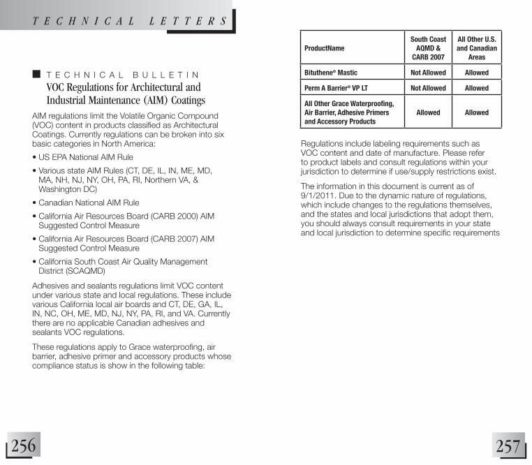
257256
regulations include labeling requirements such as VOc content and date of manufacture. Please refer to product labels and consult regulations within your jurisdiction to determine if use/supply restrictions exist.
The information in this document is current as of 9/1/2011. Due to the dynamic nature of regulations, which include changes to the regulations themselves, and the states and local jurisdictions that adopt them, you should always consult requirements in your state and local jurisdiction to determine specific requirements
n T e c h n i c a l B U l l e T i n
VOC Regulations for Architectural and Industrial Maintenance (AIM) Coatings
AIM regulations limit the Volatile Organic Compound (VOC) content in products classified as Architectural Coatings. Currently regulations can be broken into six basic categories in north america:
• US EPA National AIM Rule
• Various state AIM Rules (CT, DE, IL, IN, ME, MD, MA, NH, NJ, NY, OH, PA, RI, Northern VA, & Washington DC)
• Canadian National AIM Rule
• California Air Resources Board (CARB 2000) AIM Suggested Control Measure
• California Air Resources Board (CARB 2007) AIM Suggested Control Measure
• California South Coast Air Quality Management District (SCAQMD)
adhesives and sealants regulations limit VOc content under various state and local regulations. These include various California local air boards and CT, DE, GA, IL, IN, NC, OH, ME, MD, NJ, NY, PA, RI, and VA. Currently there are no applicable canadian adhesives and sealants VOc regulations.
These regulations apply to Grace waterproofing, air barrier, adhesive primer and accessory products whose compliance status is show in the following table:
T E C H N I C A L L E T T E r s
ProductNameSouth Coast
AQMD & CARB 2007
All Other U.S. and Canadian
Areas
Bituthene® Mastic Not Allowed Allowed
Perm A Barrier® VP LT Not Allowed Allowed
All Other Grace Waterproofing, Air Barrier, Adhesive Primers and Accessory Products
Allowed Allowed

259258
T E C H N I C A L L E T T E r s
n T e c h n i c a l B U l l e T i n
Best Practices — Sealing Preprufe® Seams Using Vee Rollers
in addition to using a traditional seam roller, we also recommend the use of a “Vee roller” to assure the adhesion and watertightness of laps and “T” joints.
The “Vee Roller” is used to seal T-joints created when Preprufe Tape is used for end laps and other details. a T-joint is formed when overlapping materials (e.g. side lap) is then overlapped by an additional layer of material (e.g. Preprufe Tape from an end lap detail). Because of the “step-down” between the overlapping materials, a channel is created that requires special attention to assure a continuous seal. The thicker the materials, the larger the step-down & thus, the larger the T-joint.
The narrow, curved, steel “Vee roller” is rolled along this channel to conform the Preprufe Tape to the step-down. run the Vee roller along the edges of the overlapping material that can be seen under the Preprufe Tape to achieve a proper seal.
NOTE: In addition to using the “Vee Roller” on the step-downs all Preprufe membrane laps (side and end) and all Preprufe Tape should still be rolled firmly with a traditional two-inch wide smooth steel roller.

261260
T E C H N I C A L L E T T E r sMR Credit 4.1: Recycled Content, 10%
MR Credit 4.2: Recycled Content, 20%
The recycled content of Grace Waterproofing materials is as follows and can contribute to earning Materials and Resources Credit 4.1 and Credit 4.2. All other Grace Waterproofing materials not listed below do not contain recycled content, 0% Post consumer and 0% Post industrial. Wt. Percent Wt. Percent Post industrial Post Consumer Grace Product Recycled Content recycled content
hydroduct® 200 89% 0% hydroduct® 220 86% 0% hydroduct® 225 83% 0% hydroduct® 660 83% 0% hydrocoil® 600 92% 0%
MR Credit 5.1: Regional Materials, 10% extracted, Processed & Manufactured Regionally
MR Credit 5.2: Regional Materials, 20% extracted, Processed & Manufactured Regionally
Grace Waterproofing materials are manufactured in several locations in north america. if these locations fall within a 500-mile radius of the project site and the location the raw materials used to make the finished product are extracted, recovered or harvested within a 500-mile radius of the project, then these materials or a portion of the materials can contribute to earning Materials and Resources Credit 5.1 and Credit 5.2.
n T e c h n i c a l B U l l e T i n
Grace Waterproofing LEED 2009 Green Building Rating System
This bulletin will detail the contribution of Grace Waterproofing materials to the LEED 2009 Green Building Rating System for New Construction, Major renovations of existing buildings, core & Shell and Schools.
MR Credit 2.1: Construction Waste Management, Divert 50% from Disposal
MR Credit 2.2: Construction Waste Management, Divert 75% from Disposal
In areas where facilities exist, the following Grace Waterproofing materials are recyclable and can contribute to earning Materials and Resources Credit 2.1 and credit 2.2.
• Wooden Pallet wood 45 lbs
• Sheet core cardboard 3 lbs/core
• Carton cardboard 4 lbs/carton
• Pail steel 2 lbs/pail
• Pail HDPE (plastic) 2 lbs/pail
• Drum steel 29 lbs/drum
• Drum fiber 12 lbs/drum

263262
T E C H N I C A L L E T T E r s
The following are the locations of the Grace Waterproofing materials manufacturing plants:
Plant location Product
Bedford Park, IL Bituthene materials
Mount Pleasant, TN Bituthene materials, Preprufe materials
Union county, nc all hydroduct materials
Please contact your local Grace Representative to request a project specific letter pertaining to Credit 5.1 and credit 5.2. The letter will provide the quantity of raw materials that are extracted, recovered or harvested within 500 miles of the project location.
MR Credit 6: Rapidly Renewable Materials
None of the Grace Waterproofing materials are made from or contain any rapidly renewable materials.
MR Credit 7: Certified Wood
None of the Grace Waterproofing materials are made from or contain any woodbased materials. MR Credit 7 is not applicable to Grace Waterproofing materials.
EQ Credit 4.2: Low Emitting Materials, Paints & Coatings
EQ Credit 4.2 pertains to products that are to be used in the interior of a building. Grace Waterproofing materials are applied onto the exterior of a structure and therefore would not contribute to this credit. However, Grace has provided the volatile organic content (VOC) of Grace Waterproofing materials listed below.
Grace Product VOC Content g/L Procor (all types) 75 (as applied)