gprs architecture trainer guide
DESCRIPTION
nokiaTRANSCRIPT

System Training
GPRS Architecture
Trainer Guide
6-64459Issue 3.0
© Nokia Oyj 1 (21)

GPRS Architecture
The information in this document is subject to change without notice and describes only the product defined in the introduction of this documentation. This document is intended for the use of Nokia's customers only for the purposes of the agreement under which the document is submitted, and no part of it may be reproduced or transmitted in any form or means without the prior written permission of Nokia. The document has been prepared to be used by professional and properly trained personnel, and the customer assumes full responsibility when using it. Nokia welcomes customer comments as part of the process of continuous development and improvement of the documentation.
The information or statements given in this document concerning the suitability, capacity, or performance of the mentioned hardware or software products cannot be considered binding but shall be defined in the agreement made between Nokia and the customer. However, Nokia has made all reasonable efforts to ensure that the instructions contained in the document are adequate and free of material errors and omissions. Nokia will, if necessary, explain issues which may not be covered by the document.
Nokia's liability for any errors in the document is limited to the documentary correction of errors. NOKIA WILL NOT BE RESPONSIBLE IN ANY EVENT FOR ERRORS IN THIS DOCUMENT OR FOR ANY DAMAGES, INCIDENTAL OR CONSEQUENTIAL (INCLUDING MONETARY LOSSES), that might arise from the use of this document or the information in it.
This document and the product it describes are considered protected by copyright according to the applicable laws.
NOKIA logo is a registered trademark of Nokia Oyj.
Other product names mentioned in this document may be trademarks of their respective companies, and they are mentioned for identification purposes only.
Copyright © Nokia Oyj 2003. All rights reserved.
2 (21) © Nokia Oyj 6-64459Issue 3.0
Contents
Contents
1 Course preparation..................................................................4
2 GPRS Architecture.....................................................................5
6-64459Issue 3.0
© Nokia Oyj 3 (21)
GPRS Architecture
2 Course preparation
Sessions General introduction
Materials Training slides, or
PowerPoint-presentation file
Flipchart
Training document
Equipment Whiteboard
Overhead projector (OHP), or
Video projector connected to PC
Empty transparencies
Markers
Preparation The Training Document binders:
4 (21) © Nokia Oyj 6-64459Issue 3.0

GPRS Architecture
3 GPRS Architecture
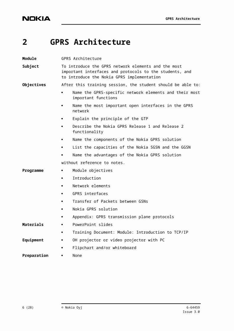
Module GPRS Architecture
Subject To introduce the GPRS network elements and the most important interfaces and protocols to the students, and to introduce the Nokia GPRS implementation
Objectives After this training session, the student should be able to:
Name the GPRS-specific network elements and their most important functions
Name the most important open interfaces in the GPRS network
Explain the principle of the GTP
Describe the Nokia GPRS Release 1 and Release 2 functionality
Name the components of the Nokia GPRS solution
List the capacities of the Nokia SGSN and the GGSN
Name the advantages of the Nokia GPRS solution
without reference to notes.
Programme Module objectives
Introduction
Network elements
GPRS interfaces
Transfer of Packets between GSNs
Nokia GPRS solution
Appendix: GPRS transmission plane protocols
Materials PowerPoint slides
Training Document: Module: Introduction to TCP/IP
Equipment OH projector or video projector with PC
Flipchart and/or whiteboard
Preparation None
6-64459Issue 3.0
© Nokia Oyj 5 (21)
GPRS Architecture
Trainer Participant Props(equipment)
Overview
Aim
This modules is divided in two parts: there is the product neutral network element description, ranging from chapter 2 to 4 and the appendix. Separated from it, there is the Nokia solution (chapter 5).
There are often customised courses. The trainer has decide, whether to cover the product neutral and Nokia specific part together or separated.
Time
Depends on the trainer’s training strategy with other modules:
chap. 2-5: 2 to 3 hours+
chap. 6: max. 3 hours
Appendix (optional): 2 hours (the appendix can be combined with the GPRS module transmission, if available in the course).
Experience
Ask each participant about his/her experience in this topic.
Gain
Ask each participant what s/he hopes to gain by this module.
Objectives
Show objectives slide.
6 (21) © Nokia Oyj 6-64459Issue 3.0

GPRS Architecture
Trainer Participant Props(equipment)
Process
The trainer generates flipchart illustrations and uses slides to proceed through the material.
The participants have the training document where the slides are embedded.
The participants have the exercises.
Most of the information presented in class can also be found in the training document.
The trainer will be asking questions throughout the course.
The participants are also encouraged to pose questions.
Contents
Module objectives
Introduction
Network elements
GPRS interfaces
Transfer of Packets between GSNs
Nokia GPRS solution
Appendix: GPRS transmission plane protocols
outline
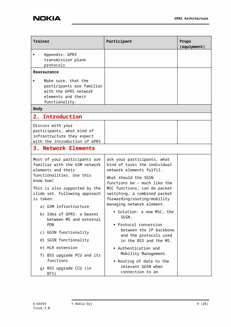
Reassurance
Make sure, that the participants are familiar with the GPRS network elements and their functionality. .
Body
2. Introduction Discuss with your participants, what kind of infrastructure they expect with the introduction of GPRS
3. Network Elements
Most of your participants are familiar ask your participants, what kind of
6-64459Issue 3.0
© Nokia Oyj 7 (21)

GPRS Architecture
Trainer Participant Props(equipment)
with the GSM network elements and their functionalities. Use this know how!
This is also supported by the slide set. Following approach is taken:
a) GSM infrastructure
b) Idea of GPRS: a bearer between MS and external PDN
c) GGSN functionality
d) SGSN functionality
e) HLR extension
f) BSS upgrade PCU and its functions
g) BSS upgrade CCU (in BTS)
h) MS classes
These components are the most important ones. The next two are specified, but it depends on the vendor, whether they are stand alone solutions are integrated in the GSNs
i) Charging Gateway
j) Border Gateway
The next elements are in use in a GPRS network infrastructure, but not specified network elements. Nokia is offering them as stand alone entities. For that reason only, they are also named here:
k) Legal intersection gateway
l) DNS server (fulfils a SGSN function)
m) Firewall
tasks the individual network elements fulfil.
What should the SGSN functions be – much like the MSC functions, can do packet switching, a combined packet forwarding/routing/mobility managing network element.
Solution: a new MSC, the SGSN.
Protocol conversion between the IP backbone and the protocols used in the BSS and the MS.
Authentication and Mobility Management.
Routing of data to the relevant GGSN when connection to an external network is required. All GPRS packets sent between two MSs of the same network must also travel via a GGSN.
Collection of charging data and traffic statistics.
Could we access external networks directly from SGSN?
Better (security, scalability, interconnection of SGSN…) to have elements that provide access to external networks: GGSN.
Interface between the GPRS network and external networks.
From the external network's point of view, the GGSN is simply a router to an IP sub-network.
When the GGSN receives data addressed to a specific user in the mobile network, it first checks if the address is active. If it is, the GGSN forwards the data to the SGSN serving the mobile.
Which are the tasks of the PCU
capacity on demand, and
8 (21) © Nokia Oyj 6-64459Issue 3.0
GPRS Architecture
Trainer Participant Props(equipment)
ps RRM
4. GPRS Interfaces
GPRS Interfaces
Name at least? interfaces between
SGSN and BSC
SGSN and GGSN
GGSN and external (IP) networks
SGSN and HLR
The interface names are really easy to forget and not so important at this stage.
Connections of the GPRS system to the NSS part of the GSM network (Gc, Gd, Gf, Gr, Gs), are SS7 based. Gs is BSSAP+. Others are MAPv3.
Other interfaces and reference points are implemented through the Intra-PLMN backbone network (Gn), the Inter-PLMN backbone network (Gp) or the external networks (Gi). The different interfaces the GPRS system uses are:
Gb interface is the carrier of the GPRS traffic and signalling between the GSM radio network (BSS) and the GPRS part. Frame Relay based Network Services provide flow control for this interface.
Gn, the Gn provides a data and signalling interface in the Intra-PLMN backbone. The GPRS Tunnelling Protocol (GTP) is used in the Gn (and in the Gp) interface over the IP based backbone network.
Gi, a reference point, depends on the external network: IP, X.25
Gr, the HLR can be located in a different PLMN than the SGSN. (MAP).
Gf between a SGSN and the EIR. The Gf gives the SGSN access to equipment information. The EIR maintains three different lists of mobile equipment: black list for stolen mobiles, grey list for mobiles under observation and white list for other mobiles. (MAP).
Gd between the SMS-GMSC and a SGSN, and between SMS-
6-64459Issue 3.0
© Nokia Oyj 9 (21)

GPRS Architecture
Trainer Participant Props(equipment)
IWMSC and a SGSN. The Gd interface allows for more efficient use of the SMS services, optional. (MAP, is implemented in Nokia solution.)
Gs between a SGSN and an MSC. The SGSN can send location data to the MSC or receive paging requests from the MSC via this optional interface. The Gs interface will greatly improve the effectiveness of the radio and network resources. (BSSAP+ is implemented in the Nokia solution).
Gc between the GGSN and the HLR. The GGSN may request the location of an MS via this optional interface. The interface could be used if the GGSN needs to forward packets to an MS that is not active.
Gp between two GSNs in various PLMNs. The Gp interface provides the same functionality as the Gn interface, but it also provides, together with the BG and the Firewall, all the functions needed for an Inter-PLMN networking, that is, security, routing, etc.
5. Transfer of Packets between GSNsThis chapter sketches the concept of tunnelling. In the Appendix, the user data transmission between GGSN and MS is described more in detail. This is already outlined here in the trainer guide
GPRS Protocols The depth of this topic is completely dependent on the technical expertise of the trainees. You might only cover tunnelling and the use of GTP, and
10 (21) © Nokia Oyj 6-64459Issue 3.0

GPRS Architecture
Trainer Participant Props(equipment)
even that is not absolutely necessary, because tunnelling is also explained in traffic management. Explaining the mobility problem of an IP host and encapsulation does, on the other hand, make understanding traffic management easier.
What was the goal of GPRS?
Motivate the use of tunnelling.
Where is mobility managed?
Possible solutions:
IP layer: either terminal changes IP address or Mobile IP => neither possible/available at the time of GPRS specifications.
Data link: SGSN handles mobility management => can not use user IP address to route packets to correct SGSN.
Solution:
Explain tunnelling in easy terms and high level.
OPTIONAL
Name and motivate the usage of other GPRS protocols, (see appendix!)
The user is connected to an external data network all the time.
The user has to have a data network address, for example an IP address.
The user has to take care of mobility.
Encapsulation of user packets in the backbone.
Used protocol: GPRS Tunnelling Protocol (GTP).
The GSM RF is the normal GSM physical radio layer. The Radio Link Control (RLC) function offers a reliable radio link to the upper layers.
6-64459Issue 3.0
© Nokia Oyj 11 (21)
GPRS Architecture
Trainer Participant Props(equipment)
The Medium Access Control (MAC) function handles channel allocation and multiplexing, that is, the use of physical layer functions. RLC and MAC together form the OSI Layer 2 protocol for the Um interface.
The Logical Link Control (LLC) layer offers a secure and reliable logical link between the MS and the SGSN to upper layers. Conveys: SMS and Subnetwork Dependent Convergence Protocol (SNDCP) packets.
SNDCP is a mapping and a compression function between the network layer and lower layers. It also performs segmentation, reassembly and multiplexing.
IP is the packet protocol offered to the subscriber by the GPRS system. PPP will also be offered in GPRS Phase2. PPP can carry also other packet protocols besides IP. Applications run on top of the chosen packet protocol.
The Base Station System GPRS Protocol (BSSGP) transfers control information and data between a BSS and an SGSN. The Network Services relay BSSGP packets over the Gb interface. The protocol implements load sharing and redundancy on top of frame relay.
The L1bis is a vendor-specific OSI Layer 1 protocol.
The Relay function relays LLC PDUs (Protocol Data Units) between the LLC and BSSGP.
The L1 and the L2 are vendor dependent OSI layer protocols.
12 (21) © Nokia Oyj 6-64459Issue 3.0

GPRS Architecture
Trainer Participant Props(equipment)
TCP and UDP are used to carry the GTP PDUs in the backbone network. TCP is used for X.25 and UDP is used for IP and signalling.
6. Nokia GPRS solution
6.1 Nokia GPRS Release functionalityExplain Nokia GPRS Release 1 and 2 features and limitations as shown in
The explanations on the Slides are self explanatory and follow from the training document and pertain to
GPRS point-to-point IP service
SGSN to MSC/VLR Interface (Gs)
Cell reselection
SMS through GPRS
Charging
Roaming
Quality of Service
Corporate access solutions
see slides 38 - 42
On the whiteboard you may tabulate the differences between Release 1 and Release 2 as you go along through this Section.
This table will be useful later.
6.2 BSS
BTS
? Ask the student which BTSs support GPRS.
? Ask the students about which CS are supported in the BTS.
All Nokia 2nd generation, Talk-family, Nokia PrimeSite and Nokia MetroSite BTSs support GPRS without any hardware changes.
Coding schemes CS1 and CS2 are supported in all Nokia BTSs.
Coding schemes CS3 and CS4 are under consideration for future releases.
CS3 and CS4 channel coding require more than one 16kbit/s
Slide 43
6-64459Issue 3.0
© Nokia Oyj 13 (21)
GPRS Architecture
Trainer Participant Props(equipment)
Abis traffic channel and can be supported in the existing BTS products only with hardware upgrades.
Currently, Nokia plans to introduce new CS3 and CS4 capable TRXs for the Talk-family and Nokia MetroSite base stations. CS3 and CS4 will not be implemented in Nokia 2nd generation BTS and Nokia PrimeSite.
PCU/BSC
Some important points to emphasise
Implementing GPRS has no effect on the capacity of the Nokia BSC to handle CS calls.
New plug-in units are required in the BSC. One Packet Control Unit (PCU) must be installed into each BCSU signalling unit of the BSC (one slot is vacant).
The PCUs support the new protocols required for GPRS and also handle channel allocation and radio channel management functions (for example broadcast control channel and power control).
One BSC contains eight active PCUs, plus one redundant PCU. One PCU can be freely connected to up to 64 cells. The maximum radio interface channels connected simultaneously to one PCU is 256, that is, a maximum of 2048 radio interface channels in GPRS use per BSC.
This means that even a high capacity 384 TRX BSC can have over 50% of its load as GPRS (assuming 8kbit/s throughput per timeslot). The data processing capacity of one PCU is 2Mbit/s. It should be noted that the BSC
slide: 44
14 (21) © Nokia Oyj 6-64459Issue 3.0

GPRS Architecture
Trainer Participant Props(equipment)
must be fully equipped with PCUs.
The number of active PCUs is determined by software licence.
Each PCU has its own separate frame relay interface to the SGSN (Gb interface). This can be configured in 64kbit/s steps, from two PCM timeslots to 31 PCM timeslots.
Packing circuit switched and GPRS traffic into the same air interface is essential for a cost-effective GPRS solution.
In the Nokia BSC, this is implemented by semi-permanently reserving resources for circuit switched or GPRS traffic.
The proportion of capacity available for each service is dynamically changed based on the circuit switched traffic load.
In this way, the performance of circuit switched traffic (that is, speech call blocking) is unaffected by the introduction of GPRS.
6.3 CNS
MSC/VLR
Work through the Questions in Slides 16. You may wish to animate this slide so that questions appear one after another.
HLR/EIR
As for circuit switched services, subscriber information for GPRS is stored in the Home Location Register (HLR).
The HLR supports procedures such as GPRS attach/detach and authentication.
Nokia has implemented
6-64459Issue 3.0
© Nokia Oyj 15 (21)
GPRS Architecture
Trainer Participant Props(equipment)
interfaces between the HLR and SGSN (Gr) as well as between the Equipment Identity Register (EIR) and SGSN (Gf). The interface implementation is MAP v.3.
For SMS support, one new parameter per subscriber has been added in the HLR to indicate whether short messages should be delivered via the MSC or the SGSN.
The optional GGSN to HLR interface (Gc) is under study for inclusion in future Nokia releases.
SGSN
? At the end of this section (5. SGSN) ask the students to summarise the features of SGSN?
The Nokia SGSN is a stand-alone unit based on the fault tolerant Nokia DX 200 platform.
The main CPUs are Intel Pentium II processors. A compact PCI bus is used within computer units.
All parts of the SGSN have either 2N hot stand-by or N+1 redundancy.
The SGSN consists of advanced router units (Packet Processing Unit, PAPU), common units for high-level mobility management (Signalling and Mobility Management Unit, SMMU), operation and maintenance (Operation and Maintenance Unit, OMU) and charging functions (MCHU).
Each PAPU serves a certain number of Routing Areas (RA). When a subscriber moves from a RA served by one PAPU to another RA served by a different PAPU, no location update is given to the HLR, minimising the load on the HLR.
One SGSN element always consists of two racks (whether fully or partly equipped).
Slide 45-47
16 (21) © Nokia Oyj 6-64459Issue 3.0

GPRS Architecture
Trainer Participant Props(equipment)
The external interfaces offered by one SGSN are:
16+1 times 100-base TX Ethernet connections to the GPRS backbone (Gn) [1 per PAPU].
Up to 1024 * 64 kbit/s frame relay links for Gb-interface towards the BSS [max. 64 x 64 kbit/s FR bearer channels per PAPU].
Up to 96 SS7 signalling links (that is, Gs, Gr, Gf, Gd) [16 x 64kbit/s links per SMMU].
Up to 120 physical E1 PCM lines (Gb, Gs, Gr, Gd, Gf). When extending the packet processing capacity of the SGSN, additional Gn- and Gb- interface capacity should be added.
The SGSN will support both header compression and user data compression (V.42 bis).
The SGSN supports 16 000 routing areas (1000 per PAPU) and 2000 location areas. One routing area is always served by one PAPU. Location areas can freely cross PAPU/SGSN boundaries.
GGSN
Explain the main features of the GGSN.
The Gateway GPRS Support Node (GGSN) provides the interconnection between the GPRS network and external packet data networks, for example the Internet.
The Nokia GGSN can support multiple access points
The Nokia implementation of the GGSN also makes it possible to run Border Gateway (BG) and
Show slides: - Nokia GPRS backbone
- GGSN features
6-64459Issue 3.0
© Nokia Oyj 17 (21)
GPRS Architecture
Trainer Participant Props(equipment)
Give the GGSN capacity.
firewall functions within the same GGSN.
The Nokia GGSN is based on Intel Pentium II processors.
Three different network interfaces are supported by the Nokia GGSN:
V.35 interface for Wide Area Network (WAN) connections
100BaseTX Ethernet Interface. This supports configurations where the SGSN(s) and GGSN(s) are located on the same site or connected to a LAN.
Synchronous Transport Module Level 1 (STM-1) Interface. For connection to Asynchronous Transfer Mode (ATM) transport or direct connection to Synchronous Digital Hierarchy (SDH) trunk lines.
The capacity of an GGSN:
Data transfer capacity of 16 Mbit/s (4-8kps).
Support for 50 000 active PDP contexts.
To provide redundancy GGSNs should be configured as N+1.
CG
Explain key CGF features.
The Nokia Charging Gateway (CGF) is a stand-alone network element that collects CDRs from the SGSN and GGSN.
The Nokia Charging Gateway will consolidate and pre-process the CDRs before passing them to the billing system.
Show slide Nokia CG architecture.
18 (21) © Nokia Oyj 6-64459Issue 3.0
GPRS Architecture
Trainer Participant Props(equipment)
Standard billing system interfaces FTAM, FTP over TCP/IP and NFS are implemented.
Scalability is achieved by adding server capacity and by internally distributing processes between computers.
To provide redundancy, Charging Gateways should be configured as N+1.
NMSExplain key NMS for GPRS features. Nokia NMS for GPRS builds on
the Nokia NMS/2000 solution (based on HP Unix workstations and servers).
Several new services have been added for managing the GPRS-based BSS and NSS parameters.
For managing the GPRS backbone, a new separate SNMP application server is used (already introduced for Nokia Artus network management).
Nokia NMS for GPRS provides an integrated solution for GPRS management. This means:
Integrated access. All applications/tools can be seamlessly accessed from the same terminal.
Combined GSM and data network management, allowing seamless co-operation between applications over organisational boundaries.
Integrated Fault Management. Both SNMP traps from the IP backbone and Q3 alarms from the GSM network are displayed and managed in
Show slide GPRS NMS solution.
6-64459Issue 3.0
© Nokia Oyj 19 (21)
GPRS Architecture
Trainer Participant Props(equipment)
the same alarm applications.
Integrated Performance Management, allowing the collection and monitoring of both GSM and data related counters.
Support for 3rd party element managers through the HP OpenView Network Node Manager-based SNMP server.
Nokia NMS for GPRS provides a seamless growth path from the current NMS/2000 GSM management system to the imminent GPRS system solution. Importantly, it is also the foundation of the management solution for the 3rd generation UMTS networks.
For GPRS service monitoring in the GSM network, the effective performance management tools found in the Nokia NMS/2000, such as measurement data post-processing and measurement data collection and storing are available.
Nokia will implement various automatic counters and measurements, enabling effective performance monitoring.
Nokia NMS will also provide reporting templates, which in turn eases the design of the required measurement palette.
In GPRS backbone management, Key Performance Indicators (KPIs) are used. The idea is that there should only be a few measurements to describe each of the following three areas:
20 (21) © Nokia Oyj 6-64459Issue 3.0

GPRS Architecture
Trainer Participant Props(equipment)
Volume of traffic - how much traffic is there in the network element?
Quality of service - how is the end user experiencing the service?
Availability of service - how accessible is the service for users?
For trend analysis and long-term statistics, Nokia has an optional product called Nokia NDW (Network Data Warehouse).
6-64459Issue 3.0
© Nokia Oyj 21 (21)