gm40ave series general purpose electronic … · para evitar el riesgo de incendio, descarga...
TRANSCRIPT

To avoid fire, shock, or death, turn off power at circuit breaker and test that power is off • before wiring.Read instructions completely before installation and retain for future reference.• Observe all national and local electrical and safety codes.• Disconnect power when servicing or changing loads.• Alterations or modifications to the device will void the warranty.• For outdoor locations, rain-tight or wet location conduit hubs that comply with the re-• quirements of UL 514B Conduit, Tubing, and Cable Fittings, must be used.
GM40AVE Series General Purpose Electronic Commercial Time Switches
To avoid fire, shock, or death, turn off power at the circuit breaker and test that 1. power is off before wiring.Open door and remove the interior protective cover by releasing the spring 2. latch (see figure 1 below).Remove the printed circuit board by releasing the spring latch holding the bot-3. tom of the board (see figure 2 below).Select knockouts to be used. Remove the inner 1/2” knockout by inserting a 4. flathead screwdriver in the slot and carefully punch the knockout loose. Re-move slug. If 3/4” knockout is required, remove the outer ring with pliers after removing the 1/2” knockout. Smooth edge with knife, if necessary.Place the enclosure in the desired mounting location, and mark the three 5. mounting holes (refer to Figure 3 below for dimensions). Install the top screw first with one of the supplied spacers, and then hang the enclosure by the key-hole. Drive the remaining two screws at the bottom of the enclosure through the mounting holes while passing each screw through one of the supplied spacers and in to the wall.Connect conduit hubs to conduit before connecting the hubs to the enclosure. 6. After inserting hubs into enclosure, carefully tighten hub lock nut. Do not over-torque. Replace printed circuit board making sure to engage spring latch at the bot-7. tom of PCB.Wire in accordance with national and local electrical and safety codes (see 8. wiring diagrams on page 3).Grounding: Terminate all ground wires to the ground lug inside the case at the 9. bottom of the enclosure.Replace interior protective cover. 10.
INSTALLATION INSTRUCTIONS
ELECTRICAL RATINGS N.O. Contacts: 40A Resistive @ 120~277VAC 1HP, 16FLA, 90LRA @ 120VAC 2HP, 12FLA, 52LRA @ 208~277VAC 30A Ballast @ 120VAC 20A Ballast @ 277VAC 15A Tungsten @ 120VAC 300VA Pilot Duty 120~240VAC
N.C. Contacts: 30A Resistive @ 120~277VAC 1HP, 12FLA, 30LRA @ 120VAC 2HP, 10FLA, 30LRA @ 240VAC 2A Tungsten @ 120VAC 10A Ballast @ 277VAC
WIRING CONNECTIONS: Screw box lug terminals
ENVIRONMENTAL RATINGS: Operating Temperature Range: –40°F to 131°F (–40°C to 55°C) Operating Humidity: 10 - 95% RH, non-condensing
ENCLOSURE DIMENSIONS: 8.795” x 6.631” x 2.935” (H x W x D)
SHIPPING WEIGHT: 2 lbs.
AGENCY APPROVALS: UL Listed
PROGRAMMING INSTRUCTIONS
WARNING
Interior Protective Cover Removed
Timer Mechanism
Figure 2 - PCB Latch
Interior Protective Cover
Figure 1 - Spring Latch
Figure 3 - Rear View of Enclosure with mounting hole dimensions
6-1/8”
2-1/2”
The installer should refer to the supplemental instruction manual included with this unit for information regarding setting the time, symbols, keys and program-ming.
AC voltage must be present at terminals L1 and L2/N for the relays to operate and the status indicator to change from 1 to 1 .

2
SPECIFIERS GUIDE
APPLICATION
The GM40AVE Series Time Controls are universal, electronic time switches designed for general purpose commercial appli-cations. The control operates on any AC voltage from 120VAC to 277VAC. The mechanism is mounted in an indoor/outdoor enclosure and has been designed for the control of lighting, heating, air conditioning, pumps, motors, or general electrical circuits in residential, commercial, industrial and agricultural facilities.
Furnish and install an Intermatic GM40AVE Auto-Volt Series with digital programmable timer with bat-tery backup. The Auto-Volt input voltage range shall be 120VAC to 277VAC, 50 / 60 Hz. All units shall incorporate two isolated sets of SPDT contacts that are each rated at 40A, 2 HP @ 277V. LED indica-tors shall provide Power and Status feedback. Enclosure shall be UL Type 3R, suitable for indoor or outdoor installation. Timers with battery backup will automatically keep time and do not require reset-ting after a power outage.
GM40AVE Digital timer controls
Moisture Resistant Conformal Coated
Board
Automatic Voltage Selection From 120 VAC to 277 VAC
40 AmpRated Contacts
One Minute Intervals
Large Screw Terminals for Easy Wiring up to #8 AWG
Large Ground Lug Termination
New UL Type 3R Enclosure for
Indoor or Outdoor Installation
Yellow and Green LED Lights Indicate Power and Status
Interior protective cover and door not shown
Built-in BatteryBackup
Easy to Read LCDScreen
Easy and Simple toProgram Timer with
Large Buttons
BASIC OPERATIONWiring and load control can be verified by manually turning the unit ON and OFF using the override (OVR) + key.
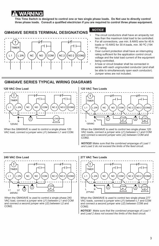
GM40AVE SERIES TERMINAL DESIGNATIONS
GM40AVE SERIES TYPICAL WIRING DIAGRAMS
COM2NO 2NC 2COMNONCL 2/NL 1
TTIMER
When the GM40AVE is used to control a single phase 120 VAC load, connect a jumper wire (J1) between L1 and COM.
When the GM40AVE is used to control a single phase 240 VAC load, connect a jumper wire (J1) between L1 and COM and connect a second jumper wire (J2) between L2 and COM2.
When the GM40AVE is used to control two single phase 120 VAC loads, connect a jumper wire (J1) between L1 and COM and connect a second jumper wire (J2) between COM and COM2.
NOTICE! Make sure that the combined amperage of Load 1 and Load 2 do not exceed the limits of the feed circuit.
When the GM40AVE is used to control two single phase 277 VAC loads, connect a jumper wire (J1) between L1 and COM and connect a second jumper wire (J2) between COM and COM2.NOTICE! Make sure that the combined amperage of Load 1 and Load 2 does not exceed the limits of the feed circuit.
COM2NO 2NC 2NONCL 2/NL 1
TTIMER
L N120VAC
COM
LOADJ1
COM2NO 2NC 2NONCL 2/NL 1
TTIMER
L1 L2240VAC
COM
LOAD #1 J1
J2
NO 2NC 2NONCL 2/NL 1
TTIMER
L N120VAC
COM
LOAD #1
LOAD #2
J1 J2
COM2
NO 2NC 2NONCL 2/NL 1
TTIMER
L N277VAC
COM
LOAD #1
LOAD #2
J2J1
COM2
120 VAC One Load
240 VAC One Load
120 VAC Two Loads
277 VAC Two Loads
This Time Switch is designed to control one or two single phase loads. Do Not use to directly control three phase loads. Consult a qualified electrician if you are required to control three phase equipment.
3
The circuit conductors shall have an ampacity not • less than the maximum total load to be controlled.For all connections, use min. 8 AWG wire for 40 A • loads or 10 AWG for 30 A loads, min. 90 oC (194 oF) rating.Over current protection shall have an interrupting • rating sufficient for the application control circuit voltage and the total load current of the equipment being controlled.A fuse or circuit breaker shall be connected in • series with each ungrounded conductor (and shall be able to simultaneously open each conductor).Jumper wires are not included.•
NOTICE
WARNING
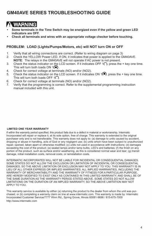
GM40AVE SERIES TROUBLESHOOTING GUIDE
PROBLEM: LOAD (Lights/Pumps/Motors, etc) will NOT turn ON or OFF
Some terminals in the Time Switch may be energized even if the yellow and green LED • indicators are OFF. Check all terminals and wires with an appropriate voltage checker before touching.•
LIMITED ONE YEAR WARRANTY If within the warranty period specified, this product fails due to a defect in material or workmanship, Intermatic Incorporated will repair or replace it, at its sole option, free of charge. This warranty is extended to the original purchaser only and is not transferable. This warranty does not apply to: (a) damage to units caused by accident, dropping or abuse in handling, acts of God or any negligent use; (b) units which have been subject to unauthorized repair, opened, taken apart or otherwise modified; (c) units not used in accordance with instructions; (d) damages exceeding the cost of the product; (e) sealed lamps and/or lamp bulbs, LED’s and batteries; (f) the finish on any portion of the product, such as surface and/or weathering, as this is considered normal wear and tear; (g) transit damage, initial installation costs, removal costs, or reinstallation costs.
INTERMATIC INCORPORATED WILL NOT BE LIABLE FOR INCIDENTAL OR CONSEQUENTIAL DAMAGES. SOME STATES DO NOT ALLOW THE EXCLUSION OR LIMITATION OF INCIDENTAL OR CONSEQUENTIAL DAMAGES, SO THE ABOVE LIMITATION OR EXCLUSION MAY NOT APPLY TO YOU. THIS WARRANTY IS IN LIEU OF ALL OTHER EXPRESS OR IMPLIED WARRANTIES. ALL IMPLIED WARRANTIES, INCLUDING THE WARRANTY OF MERCHANTABILITY AND THE WARRANTY OF FITNESS FOR A PARTICULAR PURPOSE, ARE HEREBY MODIFIED TO EXIST ONLY AS CONTAINED IN THIS LIMITED WARRANTY, AND SHALL BE OF THE SAME DURATION AS THE WARRANTY PERIOD STATED ABOVE. SOME STATES DO NOT ALLOW LIMITATIONS ON THE DURATION OF AN IMPLIED WARRANTY, SO THE ABOVE LIMITATION MAY NOT APPLY TO YOU.
This warranty service is available by either (a) returning the product to the dealer from whom the unit was pur-chased, or (b) completing a warranty claim on line at www.intermatic.com. This warranty is made by: Intermatic Incorporated Customer Service/7777 Winn Rd., Spring Grove, Illinois 60081-9698 / 815-675-7000 http://www.intermatic.com
WARNING
Verify that all wiring connections are correct. (Refer to wiring diagram on page 3)1. Check the YELLOW Power LED. If ON, it indicates that power is applied to the GM40AVE. 2. NOTE: The relays in the GM40AVE will not operate if AC power is not present.Check the status indicator on the LCD screen. If it indicates OFF 1 , press the + key one time. 3. This will turn both loads ON 1 .Check for correct voltage at terminals (NO) and/or (NO2).4. Check the status indicator on the LCD screen. If it indicates ON 1 , press the + key one time. 5. This will turn both loads OFF 1 .Check for correct voltage at terminals (NO) and/or (NO2).6. Verify that the programming is correct. Refer to the supplemental programming instruction 7. manual included with this unit.
4

Serie GM40AVE Uso general Interruptores de tiempo electrónicos comerciales
Para evitar el riesgo de incendio, descarga eléctrica o muerte, apague el suministro eléctrico del • cortacircuito y compruebe que el suministro esté apagado antes de comenzar a instalar el cab-leado.Lea las instrucciones completas antes de instalar y consérvelas para referencias futuras.• Respete todos los códigos de electricidad y seguridad nacionales y locales.• Desconecte el suministro eléctrico cuando lleve a cabo mantenimiento o realice un cambio de la • carga.Las alteraciones o modificaciones en el dispositivo invalidarán la garantía.• Para las ubicaciones en exteriores, se deberán usar concentradores de conducto contra agua o • humedad que cumplan con los requisitos de conductos UL 514B, tubería y accesorios para cable.
Para evitar el riesgo de incendio, descarga eléctrica o muerte, apague el 1. suministro eléctrico del cortacircuito y compruebe que el suministro esté apagado antes de comenzar a instalar el cableado.Abra la puerta y retire la tapa de protección interior al aflojar el seguro de 2. resorte (vea la Figura 1 de abajo).Retire el tablero de circuito impreso al aflojar el seguro de resorte y sos-3. tenga la parte inferior del tablero (vea la Figura 2 de abajo).Seleccione los troqueles a utilizar. Retire el troquel de 1/2” interior al inser-4. tar un destornillador de cabeza plana en la ranura y aflojar el troquel con cuidado. Retire el vástago. Si se requiere un troquel de 3/4”, retire el anillo exterior con unas pinzas después de retirar el troquel de 1/2”. Alise la orilla con un cuchillo, si es necesario.Coloque la carcasa en la ubicación de montaje deseada, y marque los tres 5. orificios de montaje (consulte la Figura 3 de abajo para ver las dimen-siones). Instale primero el tornillo de la parte superior con uno de los espa-ciadores provistos, y luego cuelgue la carcasa por el orificio de la cerradura. Coloque los dos tornillos restantes en la parte inferior de la carcasa a través de los orificios de montaje mientras pasa cada tornillo a través de uno de los espaciadores provistos y en la pared.Conecte los concentradores al conducto antes de conectar los concentra-6. dores a la carcasa. Después de insertar los concentradores en la carcasa, apriete con cuidado la tuerca de los concentradores. No apriete demasiado. Vuelva a colocar el tablero de circuito impreso y asegúrese de ajustar el 7. seguro de resorte en la parte inferior de la placa de circuito impreso.Instale el cableado de acuerdo con los códigos de electricidad y seguridad 8. nacionales y locales (consulte los diagramas de cableado de la página 3).Puesta a tierra: Coloque todos los cables a tierra en la terminal de puesta a 9. tierra que está adentro de la caja en la parte inferior de la carcasa.Vuelva a colocar la tapa de protección interior. 10.
INSTRUCCIONES DE INSTALACIÓN
INSTRUCCIONES DE PROGRAMACIÓN
CAPACIDAD ELÉCTRICA NOMINAL N.O. Contactos: Resistencia de 40 A a 120~277 VAC 1 HP, 16 FLA, 90 LRA a 120 VAC 2 HP, 12 FLA, 52 LRA a 208~277 VAC Balastra de 30 A a 120 VAC Balastra de 20 A a 277 VAC Tungsteno de 15 A a 120 VAC Relé auxiliar de 300 VA a 120~240 VAC
N.C. Contactos: Resistencia de 30A a 120~277 VAC 1 HP, 12 FLA, 30 LRA a 120 VAC 2 HP, 10 FLA, 30 LRA a 240 VAC Tungsteno de 2A a 120 VAC Balastra de 10A a 277 VAC
CONEXIONES DEL CABLEADO: Terminales de puesta a tierra en caja con tornillo
CAPACIDADES NOMINALES AMBIENTALES: Rango de temperatura operativa: -40°F a 131°F (-40°C a 55°C) Humedad operativa: 10 - 95% RH, sin condensación
DIMENSIONES DE LA CARCASA: 8.795” x 6.631” x 2.935” (A x A x P)
PESO AL EMBARQUE: 2 lbs.
APROBACIONES DE AGENCIA: En la lista de UL
Figura 3 - Vista posterior de la carcasa con las dimensiones del orificio
de montaje
6-1/8”
2-1/2”
ADVERTENCIA
1
El instalador deberá consultar el manual de instrucciones complementarias que se incluye con la presente unidad para obtener información relacionada con la configuración de la hora, los símbolos, las teclas y las programación.
Debe haber voltaje de CA presente en las terminales L1 y L2/N para que los relés operen y el indicador del estado cambien de 1 a 1 .
Tapa de protección interior no colocada
Mecanismo del temporizador
Figura 2 - Seguro de la tarjeta de circuito impreso
Tapa de protección interior
Figura 1 - Seguro de resorte

Tablero con recubrimiento conformado resistente a la
humedad
Contactos nominalesde 40 Amp
Intervalos de un minuto
2
La tapa y la puerta de protección interior no se muestran
Selección de voltaje automático desde 120 VAC hasta 277 VAC
Los didos emisoresde luz amarillo y verdeindican la energía y el
estado
Terminales de tornillo grande para facilidad del
cableado hasta el #8 AWG
Terminación con terminal de puesta a tierra grande
Nueva carcasa 3R tipo UL para
instalación en interiores y exteriores
Respaldo de bateríaintegrado
Pantalla de cristallíquido fácil de leer
OPERACIÓN BÁSICA
El cableado y el control de la carga se puede verificar al ACTIVAR y DESACTIVAR manualmente la unidad con la tecla de anulación +.
GUÍA DE ESPECIFICACIONES
APLICACIÓN
Equipe e instale un GM40AVE de la serie de voltaje automático Intermatic con un temporizador programable digital con respaldo de batería. El rango de voltaje de entrada de la serie de voltaje automático será de 120 VAC a 277 VAC, 50 / 60 Hz. Todas las unidades tienen dos juegos aislados de contactos SPDT cada uno nominado a 40 A, 2 HP a 277 V. Los diodos emisores de luz indican la energía y el estado. La carcasa es 3R de tipo UL, adecuada para instalaciones en interiores o exteriores. Los temporizadores con respaldo de batería conservarán la hora en forma automática y no será necesario reconfigurarlos después de un corte de energía.
Controles del temporizador digital del GM40AVE
Los controles de tiempo de la serie GM40AVE son universales, los interruptores electrónicos de tiempo están diseñados para aplicaciones comerciales de uso general. El control opera a cualquier voltaje de CA desde 120VAC hasta 277 VAC. El mecanismo está montado en una carcasa para interiores/ex-teriores y se ha diseñado para el control de luces, calefacción, aire acondicionado, bombas, motores o circuitos eléctricos en general de instalaciones residenciales, comerciales, industri-ales y agrícolas.
Temporizador con botones grandes de programación
fácil y sencilla

COM2NO 2NC 2COMNONCL 2/NL 1
TTIMER
Este interruptor de tiempo está diseñado para controlar una o dos cargas de fase sencilla. No se use para controlar directamente cargas de tres fases. Consulte a un electricista capacitado si se le requiere controlar equipos de tres fases.
Los conductores de circuito tendrán una ampacidad no menor que la carga total máxima a •controlar.Para todas las conexiones, use como mínimo un cable de 8 AWG para cargas de 40 A o de 10 •AWG para cargas de 30 A, una clasificación mínima de 90 oC (194 oF).La protección contra sobrecorrientes tendrá un rango de interrupción suficiente para el voltaje •de circuito de control de la aplicación y la corriente de la carga total del equipo que se esté controlando.Se conectará un fusible o cortacircuitos en serie con cada conductor sin conexión a tierra (y éste •podrá abrir cada conductor en forma simultánea).Los cables puente no están incluidos.•
DIAGRAMAS DE CABLEADO CARACTERÍSTICO DE LA SERIE GM40AVE
Cuando el GM40AVE se use para controlar una carga de 120 VAC de fase sencilla, conecte un cable puente (J1) entre L1 y COM.
Cuando el GM40AVE se use para controlar una carga de 240 VAC de fase sencilla, conecte un cable puente (J1) entre L1 y COM y conecte un segundo cable puente (J2) entre L2 y COM2.
Cuando el GM40AVE se use para controlar dos cargas de 120 de fase sencilla, conecte un cable puente (J1) entre L1 y COM y conecte un segundo cable puente (J2) entre COM y COM2.
¡AVISO! Asegúrese de que el amperaje combinado de la Carga 1 y la Carga 2 no exceda los límites del circuito de alimentación.
Cuando el GM40AVE se use para controlar dos cargas de 277 VAC de fase sencilla, conecte un cable puente (J1) entre L1 y COM y conecte un segundo cable puente (J2) entre COM y COM2.
¡AVISO! Asegúrese de que el amperaje combinado de la Carga 1 y la Carga 2 no exceda los límites del circuito de aliment-ación.
COM2NO 2NC 2NONCL 2/NL 1
TTIMER
L N120VAC
COM
LOADJ1
COM2NO 2NC 2NONCL 2/NL 1
TTIMER
L1 L2240VAC
COM
LOAD #1 J1
J2
NO 2NC 2NONCL 2/NL 1
TTIMER
L N120VAC
COM
LOAD #1
LOAD #2
J1 J2
COM2
NO 2NC 2NONCL 2/NL 1
TTIMER
L N277VAC
COM
LOAD #1
LOAD #2
J2J1
COM2
Una carga de 120 VAC
Una carga de 240 VAC
Dos cargas de 120 VAC
Dos cargas de 277 VAC
3
DÉSIGNATIONS DES BORNES DU GM40AVE
ADVERTENCIA
AVISO

GUÍA DE SOLUCIÓN DE PROBLEMAS DE LA SERIE GM40AV
PROBLEMA: La CARGA (Luces/Bombas/Motores, etc.) NO se ACTIVA o DESACTIVA
Algunas terminales del interruptor de tiempo pueden tener energía incluso si los diodos • emisores de luz 0indicadores están DESACTIVADOS. Verifique todas las terminales y cables con un verificador de voltaje adecuado antes de • tocarlos.
4
GARANTÍA LIMITADA DE UN AÑO Si dentro del período de garantía especificado este producto falla debido a un defecto de material o de mano de obra, Intermatic Incorporated lo reparará o reemplazará, a su entera discreción, sin cargo alguno. Esta garantía sólo se otorga al comprador original y no es transferible. Esta garantía no se aplica en los siguientes casos: (a) daños en las unidades causados por accidentes, caídas o manejo indebido, causas de fuerza may-or o uso negligente; (b) unidades que hayan sido sometidas a una reparación no autorizada, abiertas, des-montadas o modificadas de alguna manera; c) unidades no utilizadas de acuerdo con las instrucciones; (d) daños que excedan el costo del producto; (e) lámparas y/o bombillas de lámparas selladas, diodos emisores de luz (LED) y baterías; (f) el acabado de cualquier parte del producto, como su superficie y/o por exposición a la intemperie, ya que esto se considera un desgaste y uso normal; g) daños durante el transporte, costos de instalación inicial, costos de remoción o costos de reinstalación.
INTERMATIC INCORPORATED NO ASUME RESPONSABILIDAD ALGUNA POR DAÑOS INCIDENTALES O CONSECUENCIALES. ALGUNOS ESTADOS NO PERMITEN EXCLUIR O LIMITAR LOS DAÑOS INCIDEN-TALES O CONSECUENCIALES, POR LO QUE LA LIMITACIÓN O EXCLUSIÓN ANTERIOR PUDIERA NO SER VÁLIDA EN SU CASO. ESTA GARANTÍA SUSTITUYE A CUALQUIER OTRA GARANTÍA EXPRESA O IMPLÍCITA. TODAS LAS GARANTÍAS IMPLÍCITAS, INCLUIDA LA GARANTÍA DE IDONEIDAD COMERCIAL O DE IDONEIDAD PARA UN DETERMINADO FIN, SE MODIFICAN PARA QUEDAR INCLUIDAS ÚNICA-MENTE EN LA PRESENTE GARANTÍA LIMITADA, Y TENDRÁN LA MISMA DURACIÓN QUE EL PERIODO DE GARANTÍA MENCIONADO ANTES. ALGUNOS ESTADOS NO PERMITEN LIMITAR LA DURACIÓN DE UNA GARANTÍA IMPLÍCITA, POR LO QUE LA LIMITACIÓN ANTERIOR PUDIERA NO SER APLICABLE EN SU CASO.
Este servicio de garantía está disponible (a) devolviendo el producto al distribuidor donde se compró la unidad o (b) completando un reclamo de garantía en Internet en www.intermatic.com. Esta garantía es concedida por: Intermatic Incorporated Customer Service/7777 Winn Rd., Spring Grove, Illinois 60081-9698/815-675-7000 http://www.intermatic.com
ADVERTENCIA
Verifique que todas las conexiones del cableado sean las correctas. (Consulte el dia-1. grama de cableado de la página 3)Verifique el diodo emisor de luz de encendido AMARILLO. Si está ACTIVA-2. DO, éste indica que la energía está pasando al GM40AVE. NOTA: Los relés del GM40AVE no operarán si no hay energía de CA presente.Verifique el indicador del estado en la pantalla de cristal líquido. Si indica DESACTIVADO 3. 1 , presione la tecla + una vez. Esto hará que ambas cargas estén en ACTIVADO 1 .Verifique que el voltaje sea correcto en las terminales (NO) y/o (NO2).4. Verifique el indicador del estado en la pantalla de cristal líquido. Si indica ACTIVADO 5. 1 , presione la tecla + una vez. Esto hará que ambas cargas estén en DESACTIVADO 1 .Verifique que el voltaje sea correcto en las terminales (NO) y/o (NO2).6. Verifique que la programación sea la correcta. Consulte el manual de instrucciones de 7. programación complementaria que se incluye con la presente unidad.
Minuteries électroniques GM40AVE pour applications commerciales générales
CARACTÉRISTIQUES NOMINALES Contacts N.O. : 40 A résistifs à 120-277 volts c.a. 1 HP, 16 FLA, 90 LRA à 120 volts c.a. 2 HP, 12 FLA, 52 LRA à 208-277 volts c.a. 30 A Ballast à 120 volts c.a. 20 A Ballast à 277 volts c.a. 15 A tungstène à 120 volts c.a. 300 VA commande pilote 120-240 volts c.a.
Contacts N.C. : 30 A résistifs à 120-277 volts c.a. 1 HP, 12 FLA, 30 LRA à 120 volts c.a. 2 HP, 10 FLA, 30 LRA à 240 volts c.a. 2 A tungstène à 120 volts c.a. 10 A Ballast à 277 volts c.a.
CONNEXIONS DU CÂBLAGE : Bornes à vis
CARACTÉRISTIQUES NOMINALES : Échelle de température de fonctionnement : -40°C à 55°C (-40°F à 131°F) Humidité de fonctionnement : 10 - 95 % HR, sans condensation
DIMENSIONS DU BOÎTIER : 22,34 x 16,84 x 7,45 cm (8,795 x 6,631 x 2,935 po) (H x L x P)
POIDS D’EXPÉDITION : 0,907 kg (2 livres)
APPROBATIONS : UL
Pour éviter les risques d’incendie, d’électrocution ou de mort, coupez le courant au disjoncteur et vérifiez • l’absence de courant avant de procéder au câblage.
Lisez entièrement les instructions avant de procéder à l'installation et conserver celles-ci en vue d’une • référence ultérieure.
Respectez toutes les normes électriques et de sécurité nationales et locales.• Coupez le courant pendant une réparation ou un changement de charge.• Toute altération ou modification de l’appareil annule la garantie.• Pour les emplacements en extérieur, étanches à la pluie ou humides, vous devez utiliser des entrées de •
conduit respectant les exigences des conduits, tuyaux et raccords UL 514B.
Pour éviter les risques d’incendie, d’électrocution ou de mort, coupez le courant 1. au disjoncteur et vérifiez l’absence de courant avant de procéder au câblage.
Ouvrez la porte et retirez le cache intérieur de protection en appuyant sur le 2. verrou à ressort (voir la figure 1 ci-dessous).
Retirez la carte imprimée en appuyant sur le verrou à ressort qui maintient le 3. bas de la carte (voir la figure 2 ci-dessous).
Sélectionnez les alvéoles défonçables à utiliser. Retirez l’alvéole défonçable 4. intérieure de ½ po en insérant un tournevis plat dans la fente et en desserrant l’alvéole avec précaution. Retirez le capuchon. Si vous avez besoin d’une alvéole défonçable de ¾ po, retirez la bague extérieure à l’aide de pinces après avoir déposé l'alvéole défonçable de ½ po. Lissez l’arête avec un couteau, si nécessaire.
Placez le boîtier à l’emplacement de montage voulu et marquez les trois orifices 5. de montage (voir la figure 3 ci-dessous pour les dimensions). Placez d’abord la vis supérieure et l’une des entretoises fournies, puis accrochez le boîtier à la boutonnière. Insérez les deux vis restantes à travers les orifices de montage au bas du boîtier en les faisant passer chacune par les entretoises fournies, jusque dans le mur.
Effectuez le raccordement au conduit avant celui au boîtier. Puis, serrez l’écrou 6. de blocage avec précaution sans trop serrer.
Replacez la carte imprimée en veillant à la fixer à l’aide du verrou à ressort situé au bas de 7. celle-ci.
Effectuez le câblage conformément aux normes électriques et de sécurité locales 8. et nationales (voir les schémas de câblage à la page 3).
Mise à la terre : Connectez tous les fils de terre à la terre au bas du boîtier. 9. 10.Replacez le cache intérieur de protection.
DIRECTIVES D'INSTALLATION
DIRECTIVES DE PROGRAMMATION
AVERTISSEMENT
Cache intérieur de protection retiré
Mécanisme de la minuterie
Figure 2 - Verrou de la carte imprimée Figure 3 - Vue arrière du boîtier
et dimensions des orifices de montage
6-1/8”
2-1/2”
Cache intérieur de protection
Figure 1 - Verrou à ressort
L’installateur doit s’y reporter pour obtenir des informations sur la configuration de l’heure, les symboles, les touches et la program-mation.
Les bornes L1 et L2/N doivent être alimentées en courant CA pour que les relais fonctionnent et que le témoin d’état passe de 1 à 1 .
1

SPÉCIFICATIONS
APPLICATION
Installez la minuterie numérique programmable Intermatic GM40AVE avec pile de secours. La plage de tensions doit être comprise entre 120 et 277 volts c.a., 50/60 HZ. Tous les dispositifs doivent comprendre deux jeux isolés de contacts unipolaires bidirectionnels de 40 A, 2 HP à 277 volts. Les DEL doivent indiquer l’état de l’alimentation et de l’appareil. Le boîtier doit être un boîtier UL de type 3R, conçu pour une installation en extérieur ou à l’intérieur. Les minuteries avec pile de secours conservent l’heure et ne requièrent pas de reconfiguration après une coupure de courant.
Circuit imprimé con-forme
résistant à l’humidité
Contacts rominauxde 40 A
Intervalles d’une (1)minute
2
La porte et le cache de protection intérieurs ne sont pas illustrés.
Sélection automatique de la tension (de 120 à 277 volts c.a.)
Del jaune et verte indiquant l’étt de l’alimentation et de
l’appareil
Bornes à vis larges pour un câblage facile
jusqu’à 8 AWG
Raccordement à la terre à grande cosse
Nouveau boîtier UL de type 3R pour
l’extérieur et l’intérieur Configuration
Pile de seccursintégrée
Écran ACL à lectureaisée
Chronocontrôles numériques GM40AVE
Les chronocontrôles GM40AVE sont des minuteries électro-niques universelles, conçues pour des applications commer-ciales générales. Elles utilisent une tension CA comprise entre 120 et 277 volts c.a. Le mécanisme est monté dans un boîtier d’extérieur/intérieur conçu pour le contrôle de l’éclairage, du chauffage, de la climatisation, des pompes, des moteurs ou des circuits électriques généraux de locaux particuliers, com-merciaux, industriels et agricoles.
FONCTIONNEMENT DE BASELe câblage et le contrôle des charges peuvent être manuellement vérifiés en activant/désactivant le dispositif à l’aide de la touche + de surpassement (OVR).
Minuterie facilementprogrammableavec
boutons larges

Contacts rominauxde 40 A
Minuterie facilementprogrammableavec
boutons larges
COM2NO 2NC 2COMNONCL 2/NL 1
TTIMER
Cette minuterie est conçue pour contrôler des charges monophasées ou biphasées. Ne l’utilisez pas pour contrôler directement des charges triphasées. Consultez un électricien qualifié si vous devez contrôler un équipement triphasé.
L’intensité admissible des conducteurs du circuit ne doit pas être inférieure à l’intensité • totale maximale à contrôler.
Pour toutes les connexions, utilisez un câble d’au moins 8 AWG pour une intensité de • 40 A ou 10 AWG pour une intensité de 30 A, pour une température nominale min. de 90 oC (194 oF).
Le pouvoir de coupure nominal de la protection contre les surintensités doit être suffisant • pour la tension du circuit de contrôle et la tension totale de l’équipement sous contrôle.
Un disjoncteur (pour le circuit ou les fusibles) doit être connecté en série à chaque • conducteur non relié à la terre (et doit être capable d’ouvrir chaque conducteur simultanément).
Les cavaliers ne sont pas inclus.•
AVIS
AVERTISSEMENT
SCHÉMAS DE CÂBLAGE STANDARD DU GM40AVE
Lorsque vous utilisez le GM40AVE pour contrôler une charge monophasée de 120 volts c.a., installez un cavalier (J1) entre L1 et COM.
Lorsque vous utilisez le GM40AVE pour contrôler des charges monophasées de 240 volts c.a., installez un cavalier (J1) entre L1 et COM, puis un deuxième cava-lier (J2) entre L2 et COM2.
Lorsque vous utilisez le GM40AVE pour contrôler des charges biphasées de 120 volts c.a., installez un cava-lier (J1) entre L1 et COM, puis un deuxième cavalier (J2) entre COM et COM2. AVIS ! Vérifiez que la combinaison des intensités de la charge 1 et de la charge 2 ne dépasse pas les limites du circuit d’alimentation.
Lorsque vous utilisez le GM40AVE pour contrôler des charges biphasées de 277 volts c.a., installez un cava-lier (J1) entre L1 et COM, puis un deuxième cavalier (J2) entre COM et COM2.AVIS ! Vérifiez que la combinaison des intensités de la charge 1 et de la charge 2 ne dépasse pas les limites du circuit d’alimentation.
COM2NO 2NC 2NONCL 2/NL 1
TTIMER
L N120VAC
COM
LOADJ1
COM2NO 2NC 2NONCL 2/NL 1
TTIMER
L1 L2240VAC
COM
LOAD #1 J1
J2
NO 2NC 2NONCL 2/NL 1
TTIMER
L N120VAC
COM
LOAD #1
LOAD #2
J1 J2
COM2
NO 2NC 2NONCL 2/NL 1
TTIMER
L N277VAC
COM
LOAD #1
LOAD #2
J2J1
COM2
Charge monophasée de 120 volts c.a.
Charges monophasées de 240 volts c.a.
Charges biphasées de 120 volts c.a.
Charges biphasées de 277 Volts c.a.
3
DÉSIGNATIONS DES BORNES DU GM40AVE

GUIDE DE DÉPANNAGE DU GM40AVE
PROBLÈME : La CHARGE (éclairage/pompe/moteurs, etc.) NE s’ACTIVE PAS ou NE se DÉSACTIVE PAS.
Certaines bornes de la minuterie sont alimentées même si les DEL jaune et • verte sont ÉTEINTES. Vérifiez tous les câbles et bornes à l’aide d’un voltmètre approprié avant de les • toucher.
AVERTISSEMENT
158--00890
INTERMATIC INCORPORATED SPRING GROVE, ILLINOIS 60081
www.Intermatic.com
GARANTIE LIMITÉE D’UN AN Si, au cours de la période indiquée, ce dispositif présente une défectuosité de matériel ou de fabrication, Intermatic Incorporated s'engage à le réparer ou le remplacer, à sa seule discrétion, sans frais. Cette garantie s’applique uniquement à l’acheteur original et elle est incessible. Cette garantie ne s'applique pas : (a) aux dommages au dispositif causés par un accident, une chute ou une mauvaise manipulation, une catastrophe naturelle ou une utilisation négligente ; (b) aux dispositifs soumis à des réparations non autorisées, qui ont été ouverts, démontés ou modifiés de quelconque manière ; (c) aux dispositifs qui n'ont pas été utilisés selon les directives ; (d) aux dommages dépassant le coût du produit ; (e) aux lampes scellées et/ou aux ampoules, aux DEL et aux piles ; (f) à la finition de l'une des parties du dispositif, telle que la surface ou les caractéristiques de résistance aux intempéries, ce qui est considéré comme de l'usure normale ; (g) aux dommages causés par le transport, aux coûts d'installation initiale, aux coûts de démontage ou de remontage.
INTERMATIC INCORPORATED NE POURRA ÊTRE TENUE RESPONSABLE DE DOMMAGES ACCIDEN-TELS OU CONSÉCUTIFS. CERTAINS ÉTATS N'AUTORISENT PAS L'EXCLUSION OU LA LIMITATION DE DOMMAGES ACCIDENTELS OU CONSÉCUTIFS. DANS CE CAS, LES LIMITES CI-DESSUS NE S'APPLIQUENT PAS. CETTE GARANTIE REMPLACE TOUTES LES AUTRES GARANTIES EXPRESSES OU IMPLICITES. TOUTES LES GARANTIES IMPLICITES, Y COMPRIS LA GARANTIE DE COMMER-CIALISATION ET LA GARANTIE DE CONFORMITÉ À UNE FIN PRÉVUE, SONT PAR LA PRÉSENTE MODIFIÉES POUR EXISTER UNIQUEMENT TELLES QUE COMPRISES DANS LA GARANTIE LIMITÉE, ET AURONT LA MÊME DURÉE QUE LA PÉRIODE DE GARANTIE DÉCLARÉE CI-DESSUS. CERTAINS ÉTATS N’ACCEPTENT PAS DE LIMITES SUR LA DURÉE D’UNE GARANTIE IMPLICITE. DANS CE CAS, LA LIMITE PEUT NE PAS VOUS CONCERNER.
Le service de garantie est disponible soit (a) par retour du produit au vendeur auprès duquel le dispositif a été acheté soit (b) en remplissant le formulaire de réclamation sur le site Web www.intermatic.com. Cette garantie est accordée par : Intermatic Incorporated / 7777 Winn Rd., Spring Grove, Illinois 60081-9698 / 815-675-7000 http://www.intermatic.com
Vérifiez que toutes les connexions ont été correctement effectuées. (Voir le schéma 1. de câblage à la page 3.)Vérifiez la DEL JAUNE d’alimentation. 2. Si elle est ALLUMÉE, le GM40AVE est alimenté. REMARQUE : Les relais du GM40AVE ne fonctionnent pas si ce dernier n’est pas alimenté en courant CA.Vérifiez le témoin d’état sur l’écran ACL. S’il indique OFF 1 (ARRÊT 1) , appuyez 3. une fois sur la touche +. Les deux charges sont activées ON 1 (MARCHE 1) .Vérifiez la tension aux bornes (NO) et/ou (NO2).4. Vérifiez le témoin d’état sur l’écran ACL. S’il indique ON 1 (MARCHE 1) , appuyez 5. une fois sur la touche +. Les deux charges sont désactivées OFF 1 (ARRÊT 1) .Vérifiez la tension aux bornes (NO) et/ou (NO2).6. Vérifiez que la programmation est correcte. Voir le manuel de directives de program-7. mation complémentaire fourni avec ce dispositif.
4