giampaolo manfrida , lorenzo tallurithermalscience.vinca.rs/pdfs/papers-2018/tsci160601170m.pdf ·...
TRANSCRIPT
FLUID DYNAMICS ASSESSMENT OF THE TESLA TURBINE ROTOR
Giampaolo Manfrida*1
, Lorenzo Talluri1
1Department of Industrial Engineering, University of Florence, Viale Morgagni 40-44, Florence, Italy
*Corresponding author; E-mail: [email protected]
The Tesla turbine seems to offer several points of attractiveness when
applied to low-power applications. Indeed, it is a simple, reliable, and low
cost machine. The principle of operation of the turbine relies on the
exchange of momentum due to the shear forces originated by the flow of
the fluid through a tight gap among closely stacked disks.
This turbine was firstly developed by Tesla at the beginning of the 20th
century, but it did not stir up much attention due to the strong drive
towards large centralized power plants; on the other hand, in recent
years, as micro power generation gained attention on the energy market
place, this original expander raised renewed interest.
The mathematical model of the Tesla turbine rotor is revised in this paper,
and adapted to real gas operation. The model is first validated by
comparison with other assessed literature models. The optimal
configuration of the rotor geometry is then investigated running a
parametric analysis of the fundamental design parameters. High values of
efficiency (isolated rotor) were obtained for the optimal configuration of
the turbine, which appears interesting for small-scale power generation.
The rotor efficiency depends on the configuration of the disks, particularly
on the gap and on the outlet diameter, which determines largely the
kinetic energy at discharge.
Key words: Tesla Turbine, Mathematical model, Rotor efficiency
1. Micro generation and the Tesla Turbine
In recent years, distributed micro generation of power has become of paramount consideration
by industries, governments and research institutions.
One of the main problems of micro generation of power in thermal energy conversion
applications is related to the expander, as this component often presents high manufacturing costs and
low reliability. The Tesla turbine seems to tackle these problems. Its simple structure ensures a very
reliable and low-cost machine.
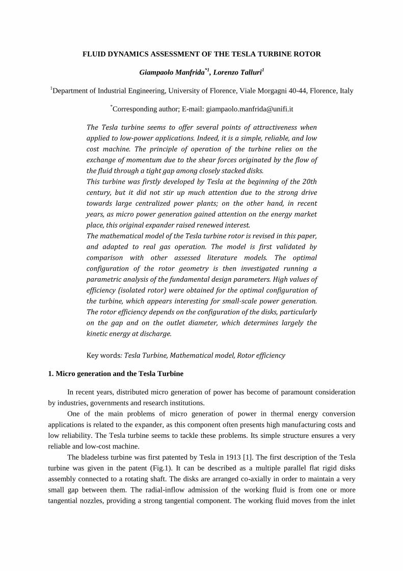
The bladeless turbine was first patented by Tesla in 1913 [1]. The first description of the Tesla
turbine was given in the patent (Fig.1). It can be described as a multiple parallel flat rigid disks
assembly connected to a rotating shaft. The disks are arranged co-axially in order to maintain a very
small gap between them. The radial-inflow admission of the working fluid is from one or more
tangential nozzles, providing a strong tangential component. The working fluid moves from the inlet
to the outlet radius due to the difference in pressure determined by friction and by the exchange of
momentum, and exits from openings made on the disks and/or shaft at the inner radius.
Fig. 1 – Figures from the patent of Tesla, 1913 [1]
The Tesla turbine did not encounter much success when it was proposed, and eventually it was
not investigated deeply and further developed for a long time.
Only in the 1950s Armstrong built an experimental test rig to investigate the performance of the
disk turbine [2]. He conducted a test campaign, with steam as working fluid and different nozzle
configurations. A valuable result was the understanding of one of the causes of inefficiency. Indeed, it
was found that the nozzle flow strongly affects the performance of the turbine.
After the Armstrong tests the Tesla turbine was not investigated for another 15 years. Only with
Rice [3], a sound analytic/numerical model, based on the physics of the flow, was developed. The
radial velocity rises proceeding towards the centre due to the reduction of the flow area. The tangential
velocity is determined by the local balance of the force components (momentum/friction). The
mathematical model performed a notable simplification of the Navier-Stokes equations, allowing
tackling the solution with the first computers available at the time. The main assumptions were to
consider steady flow of an inviscid incompressible working fluid. Rice also built and tested 6 different
types of disk turbines, with air as working fluid.
After Rice’s pioneer work, research on the Tesla turbine was set aside until recent times. Lately,
new research has flourished on the subject.
Hoya and Guha [4] designed and built a new test rig for measuring the output torque and power
of a Tesla turbine. In a following work [5], Guha and Smiley investigated the nozzle recognizing it as
the source of the major irreversibility according to their test results; they demonstrated that a careful
design of the nozzle could reduce the nozzle losses by 40-50 %. Also Neckel and Godinho [6] focused
their research on nozzle geometry. In their research 10 nozzles were designed, manufactured and
tested with air as working fluid. Their study confirmed that the nozzle is the critical component of the
turbine and that an adequate design could contribute to increase the overall efficiency of the turbine.
Carey [7] presented an assessment of the disc turbine for a small-scale application. He
developed an analytical solution of the governing equations, declaring an achievable isentropic
efficiency of 75% in optimal design conditions. A complete computational and theoretical modelling
of the flow inside a Tesla turbine was presented by Carey [8]. In this work, he fully explains the
advantages and drawbacks of computational and analytical analysis. Furthermore, Carey also
discusses the advantages of using this expander for green-energy applications. Guha and Sengupta [9,
10] developed an accurate fluid dynamics model of the turbine, considering individually the role of
each force (centrifugal, Coriolis, inertial and viscous). Lemma et al. and Guha and Sengupta [11, 12],
also developed a CFD analysis and a general characterization of the performance of the Tesla turbine.
The development of a micro Tesla turbine was investigated by Romanin et al. [13]. In this
study, the experimental data showed that a 1 cm rotor could achieve an efficiency of 36 %. Starting
from these data, Krishan et al. [14] developed scaling laws and gave recommendations for the
development of a 1 mm Tesla turbine. Guha and Sengupta also developed a similitude study on the
flow of the Tesla turbine [15]. The scaling laws were obtained through the Buckingham Pi theorem,
which lead to the definition of 7 fundamental non-dimensional numbers. A further study of Guha and
Sengupta [16] demonstrated that the application of the Euler turbomachinery equation is consistent
only if local velocity mass-averaged values are considered. Recent published work on the Tesla
turbine deals with the investigation of nanofluids applications [17]; an increase of power output of
30% appears to be possible when the volume fraction of nanoparticles is increased from 0 to 0.05.
There are several interesting studies on experimental tests of Tesla turbines and on the
development of its flow model. However, there still exists a literature gap on the fluid dynamics
analysis of the rotor for compressible fluids, as well as for real-fluid effects which are likely using
refrigerants or advanced working fluids utilized for low-power and low-temperature applications.
Therefore, the principal aim of this study is to build a mathematical model of the rotor in order
to assess the correct geometry, as well as to assemble a numerical tool to evaluate the performance of
the Tesla turbine.
2. Model of the Rotor Flow
2.1. General Flow Equations and assumptions
The model for the rotor flow is derived from [3, 7, 9] with some relevant changes:
The hypothesis of incompressible flow with constant density is removed;
Density – as well as all other thermodynamic functions – is taken as a fluid property
depending on the local variables (typically, pressure and temperature);
A real fluid model is applied (no perfect gas assumptions).
Because of these assumptions, the equations are solved numerically with fluid properties locally
evaluated by EES. Furthermore, in order to develop a sound analytical model, additional assumptions
have been made:
a) Steady, laminar flow.
b) The viscous force is treated as a body force acting on the flow at each (r - θ) position.
c) Two-dimensional flow:
;
;
.
d) Radial symmetric flow field, uniform at the inlet (r = r0). The flow field is thus the same
for any θ, therefore the derivative = 0 for all flow variables.
e) negligible compared to wall friction forces.

Taking into account the previous assumptions, the fundamental Navier-Stokes equations in
cylindrical coordinates are reduced to:
Continuity
(1)
Momentum, r-direction
(2)
Momentum, θ-direction
(3)
Momentum, z-direction
(4)
The integration of the reduced continuity equation (1) results in . Furthermore,
knowing the mass flow rate inside each channel, it follows that locally:
(5)
2.2. Formulation of the viscous shear stress
Considering a fluid element between the two disks defining the flow channel, a control volume
Ve can be defined with base surface Ae and height b. The fluid wetted area is . Therefore,
the hydraulic diameter is equal to 2b.Consequently,
(6)
For laminar flow, the wall shear effect can be expressed as a function of a friction factor and
of the relative velocity of the flow. Equation (7) displays the expression of the wall shear stress,
decomposing the relative velocity in its two components.
(7)
Considering and as usual for laminar flow between parallel
plates:
(8)
So that:
(9)
The force resulting from wall friction force is given by the product of the wall shear with the
wetted area:
(10)
The wall friction force has a tangential and a radial component, which influence respectively the
torque and the radial pressure gradient.
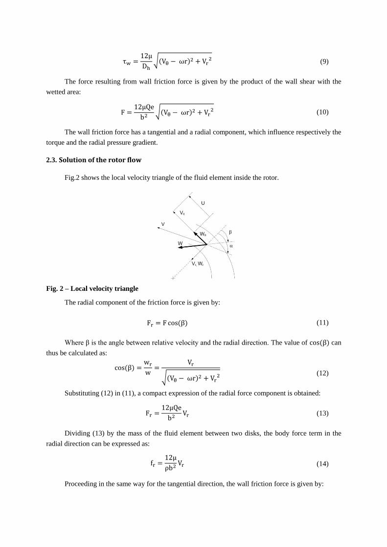
2.3. Solution of the rotor flow
Fig.2 shows the local velocity triangle of the fluid element inside the rotor.
Fig. 2 – Local velocity triangle
The radial component of the friction force is given by:
(11)
Where β is the angle between relative velocity and the radial direction. The value of can
thus be calculated as:
(12)
Substituting (12) in (11), a compact expression of the radial force component is obtained:
(13)
Dividing (13) by the mass of the fluid element between two disks, the body force term in the
radial direction can be expressed as:
(14)
Proceeding in the same way for the tangential direction, the wall friction force is given by:

(15)
(16)
Similarly, substituting (16) in (15), a compact expression of the tangential force is obtained:
(17)
The body force in tangential direction is thus given by:
(18)
In order to determine the local pressure, (14) is substituted in (2):
(19)
Using (5), the local derivative can be expressed as:
(20)
Finally, substituting (20) in (19) the pressure gradient in radial direction is given by:
(21)
Likewise, in order to compute the tangential velocity, (18) can be substituted in (3):
(22)
Obtaining finally:
(23)
Which determines the profile of (r).
2.4. Flow Model Results - Validation
Equations (21) and (23) were programmed into a two-dimensional (r and coordinates) EES
[18] code with a second-order finite difference approximation. In order to validate the model, it was
decided to run the simulations for the same data documented in [3] and for incompressible fluid.
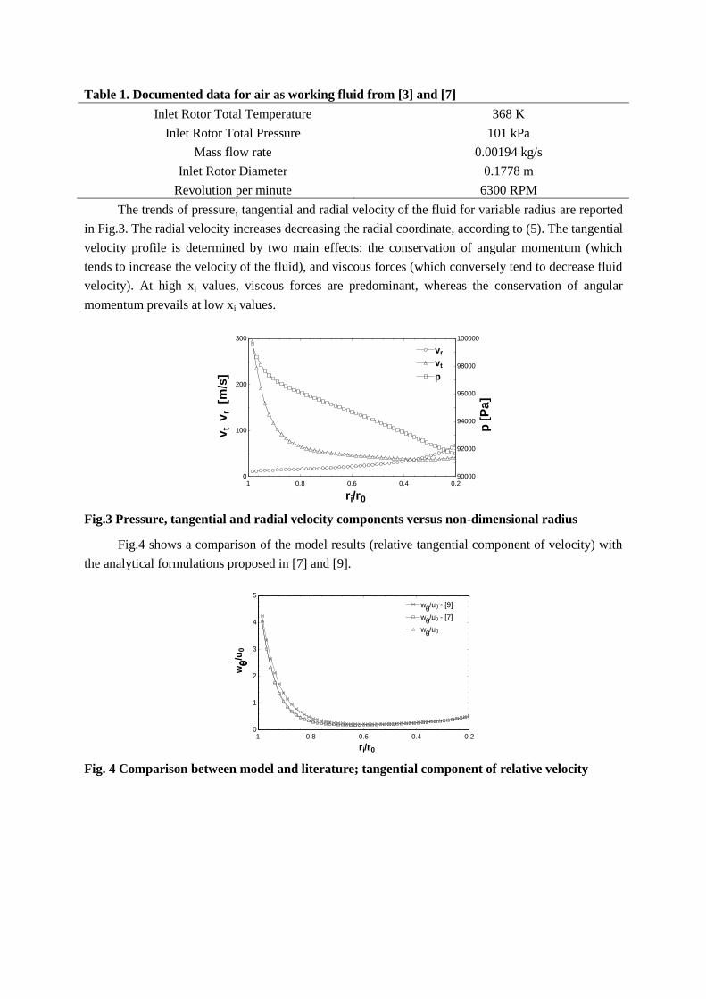
Table 1. Documented data for air as working fluid from [3] and [7]
Inlet Rotor Total Temperature 368 K
Inlet Rotor Total Pressure 101 kPa
Mass flow rate 0.00194 kg/s
Inlet Rotor Diameter 0.1778 m
Revolution per minute 6300 RPM
The trends of pressure, tangential and radial velocity of the fluid for variable radius are reported
in Fig.3. The radial velocity increases decreasing the radial coordinate, according to (5). The tangential
velocity profile is determined by two main effects: the conservation of angular momentum (which
tends to increase the velocity of the fluid), and viscous forces (which conversely tend to decrease fluid
velocity). At high xi values, viscous forces are predominant, whereas the conservation of angular
momentum prevails at low xi values.
Fig.3 Pressure, tangential and radial velocity components versus non-dimensional radius
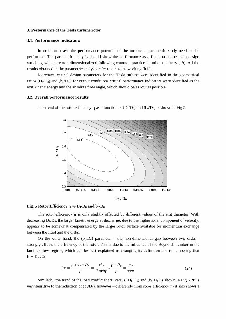
Fig.4 shows a comparison of the model results (relative tangential component of velocity) with
the analytical formulations proposed in [7] and [9].
Fig. 4 Comparison between model and literature; tangential component of relative velocity
0.20.40.60.810
100
200
300
90000
92000
94000
96000
98000
100000
ri/r0
vt v
r [
m/s
]
p [
Pa
]
vrvr
vtvt
pp
0.20.40.60.810
1
2
3
4
5
ri/r0
wq
/u0
wq/u0 - [7]w
q/u0 - [7]
wq/u0 w
q/u0
wq/u0 - [9]w
q/u0 - [9]
3. Performance of the Tesla turbine rotor
3.1. Performance indicators
In order to assess the performance potential of the turbine, a parametric study needs to be
performed. The parametric analysis should show the performance as a function of the main design
variables, which are non-dimensionalized following common practice in turbomachinery [19]. All the
results obtained in the parametric analysis refer to air as the working fluid.
Moreover, critical design parameters for the Tesla turbine were identified in the geometrical
ratios (D1/D0) and (b0/D0); for output conditions critical performance indicators were identified as the
exit kinetic energy and the absolute flow angle, which should be as low as possible.
3.2. Overall performance results
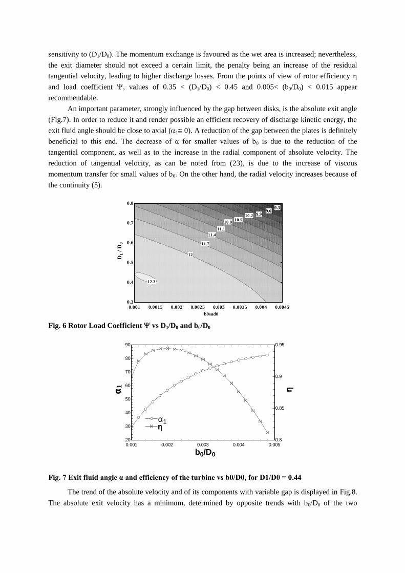
The trend of the rotor efficiency as a function of (D1/D0) and (b0/D0) is shown in Fig.5.
Fig. 5 Rotor Efficiency vs D1/D0 and b0/D0
The rotor efficiency is only slightly affected by different values of the exit diameter. With
decreasing D1/D0, the larger kinetic energy at discharge, due to the higher axial component of velocity,
appears to be somewhat compensated by the larger rotor surface available for momentum exchange
between the fluid and the disks.
On the other hand, the (b0/D0) parameter - the non-dimensional gap between two disks -
strongly affects the efficiency of the rotor. This is due to the influence of the Reynolds number in the
laminar flow regime, which can be best explained re-arranging its definition and remembering that
:
(24)
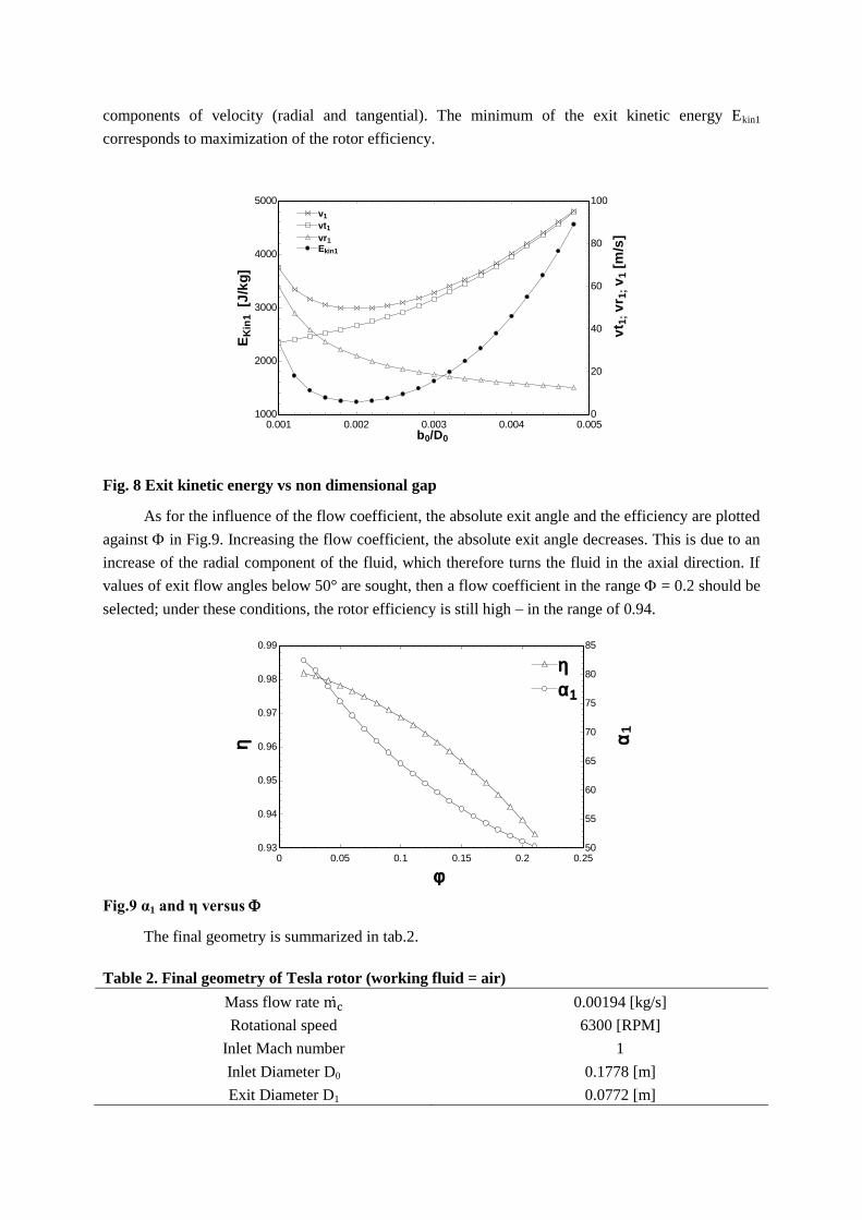
Similarly, the trend of the load coefficient versus (D1/D0) and (b0/D0) is shown in Fig.6. is
very sensitive to the reduction of (b0/D0); however – differently from rotor efficiency η- it also shows a
0.001 0.0015 0.002 0.0025 0.003 0.0035 0.004 0.00450.3
0.4
0.5
0.6
0.7
0.8
b0 / D0
D1 /
D0
0.780.8
0.820.840.860.88
0.90.92
0.94
sensitivity to (D1/D0). The momentum exchange is favoured as the wet area is increased; nevertheless,
the exit diameter should not exceed a certain limit, the penalty being an increase of the residual
tangential velocity, leading to higher discharge losses. From the points of view of rotor efficiency
and load coefficient , values of 0.35 < (D1/D0) < 0.45 and 0.005< (b0/D0) < 0.015 appear
recommendable.
An important parameter, strongly influenced by the gap between disks, is the absolute exit angle
(Fig.7). In order to reduce it and render possible an efficient recovery of discharge kinetic energy, the
exit fluid angle should be close to axial (1 0). A reduction of the gap between the plates is definitely
beneficial to this end. The decrease of α for smaller values of b0 is due to the reduction of the
tangential component, as well as to the increase in the radial component of absolute velocity. The
reduction of tangential velocity, as can be noted from (23), is due to the increase of viscous
momentum transfer for small values of b0. On the other hand, the radial velocity increases because of
the continuity (5).
Fig. 6 Rotor Load Coefficient vs D1/D0 and b0/D0
Fig. 7 Exit fluid angle α and efficiency of the turbine vs b0/D0, for D1/D0 = 0.44
The trend of the absolute velocity and of its components with variable gap is displayed in Fig.8.
The absolute exit velocity has a minimum, determined by opposite trends with b0/D0 of the two
0.001 0.0015 0.002 0.0025 0.003 0.0035 0.004 0.00450.3
0.4
0.5
0.6
0.7
0.8
b0sud0
D1 /
D0
9.39.6
9.910.210.5
10.8
11.1
11.4
11.7
12
12.3
0.001 0.002 0.003 0.004 0.00520
30
40
50
60
70
80
90
0.8
0.85
0.9
0.95
b0/D0
a1 h
hha1a1
components of velocity (radial and tangential). The minimum of the exit kinetic energy Ekin1
corresponds to maximization of the rotor efficiency.
Fig. 8 Exit kinetic energy vs non dimensional gap
As for the influence of the flow coefficient, the absolute exit angle and the efficiency are plotted
against in Fig.9. Increasing the flow coefficient, the absolute exit angle decreases. This is due to an
increase of the radial component of the fluid, which therefore turns the fluid in the axial direction. If
values of exit flow angles below 50° are sought, then a flow coefficient in the range = 0.2 should be
selected; under these conditions, the rotor efficiency is still high – in the range of 0.94.
Fig.9 α1 and η versus
The final geometry is summarized in tab.2.
Table 2. Final geometry of Tesla rotor (working fluid = air)
Mass flow rate 0.00194 [kg/s]
Rotational speed 6300 [RPM]
Inlet Mach number 1
Inlet Diameter D0 0.1778 [m]
Exit Diameter D1 0.0772 [m]
0.001 0.002 0.003 0.004 0.0051000
2000
3000
4000
5000
0
20
40
60
80
100
b0/D0
EK
in1 [J
/kg
]
vt 1
; v
r 1; v
1 [
m/s
]
Ekin1Ekin1
v1v1
vr1vr1
vt1vt1
0 0.05 0.1 0.15 0.2 0.250.93
0.94
0.95
0.96
0.97
0.98
0.99
50
55
60
65
70
75
80
85
f
h a1
hh
a1a1

Gap b0 0.00032 [m]
Absolut exit angle α1 52 [°]
Power produced for each channel 40.8 [W]
Exit Mach number 0.1168
4. Conclusions
An upgraded description of the Tesla turbine rotor flow was presented and validated against
similar literature models. The new model includes variable density and applies a real fluid model (no
incompressible fluid or perfect gas assumptions). Existing experience with prototypes of Tesla
turbines has always dealt with air or steam as working fluid, so that the capability of modelling general
fluids looks potentially attractive.
The model was applied to evaluate the sensitivity of performance to the most relevant design
variables, that is: D1/D0; b0/D0; and the flow coefficient. The main calculated performance parameters
analysed are the total-to-static efficiency and the work coefficient.
The results indicate that the Tesla rotor appears potentially competitive with other types of
expanders, with special reference to efficiency.
Nomenclature
A surface, [m2]
b gap between two discs, [m]
Dh hydraulic diameter, [m]
body force per unit mass, [m/s2]
E kinetic energy, [J/kg]
F force, [N]
h enthalpy, [J/kg] .
m mass flow rate, [kg/s]
p pressure, [Pa]
Q volume, [m3]
r local radius, [m]
Re Reynolds number (relative flow)
rpm rotational speed, [rpm]
T temperature, [°C]
U tangential velocity, [m/s]
V absolute velocity, [m/s]
x non-dimensional radius
w Relative velocity, [m/s]
W power, [W]
Greek symbols
absolute flow angle, [°]
relative flow angle, [°]
friction factor
total-to-static efficiency (rotor only)
dynamic viscosity, [kg/(ms)]
ν kinematic viscosity, [m2/s]
ρ density, [kg/m3]
τ wall shear stress, [Pa]
flow coefficient
load
coefficient
rotational speed, [rad/s]
Subscripts and superscripts
0 rotor inlet value
1 rotor outlet value
e fluid element
i point i
kin kinetic
r radial direction
t time, [s]
w wetted wall
z axial direction
tangential direction
References
[1] Tesla, N., Turbine, U.S. Patent No. 1 061 206, (1913).
[2] Armstrong, J.H., An Investigation of the Performance of a Modified Tesla Turbine, M.S.
Thesis, Georgia Institute of Technology, (1952).
[3] Rice, W., An analytical and experimental investigation of multiple-disk turbines, ASME
Journal of Engineering for Power, 87, (1965), 1, pp. 29-36.
[4] Hoya, G.P. and Guha, A., The design of a test rig and study of the performance and efficiency
of a Tesla disc turbine, Proceedings of the Institution of Mechanical Engineers, Part A:
Journal of Power and Energy, (2009), 223, pp. 451-465.
[5] Guha, A., and Smiley, B., Experiment and analysis for an improved design of the inlet and
nozzle in Tesla disc turbines, Proceedings of the Institution of Mechanical Engineers, Part A:
Journal of Power and Energy, (2009), 224, pp. 261-277.
[6] Neckel A.L., and Godinho, M., Influence of geometry on the efficiency of convergent-
divergent nozzles applied to Tesla turbines, Experimental Thermal and Fluid Science, 62,
(2015), pp. 131-140.
[7] Carey, V.P., Assessment of Tesla Turbine Performance for Small Scale Rankine Combined
Heat and Power Systems, Journal of Eng. for Gas Turbines and Power, (2010), 132.
[8] Carey, V.P., Computational/Theoretical Modeling of Flow Physics and Transport in Disk
Rotor Drag Turbine Expanders for Green Energy Conversion Technologies, Proceedings of
the ASME 2010 International Mechanical Engineering Congress and Exposition, (2010), 11,
pp. 31-38.
[9] Guha, A., and Sengupta S., The fluid dynamics of the rotating flow in a Tesla disc turbine,
European Journal of Mechanics B/Fluids, 37, (2013), pp. 112-123.
[10] Sengupta, S., and Guha, A., A theory of Tesla disc turbines, Proceedings of the Institution of
Mechanical Engineers, Part A; Journal of Power and Energy, (2012).
[11] Lemma, E., Deam, R.T., Toncich, D., Collins, R., Characterisation of a small viscous flow
turbine, Experimental Thermal and Fluid Science, 33, (2008), pp. 96-105.
[12] Sengupta, S. and Guha A., Analytical and computational solutions for three-dimensional flow-
field and relative pathlines for the rotating flow in a Tesla disc turbine, Computers & Fluids,
(2013), 88, pp. 344-353.
[13] Romanin, V.D., Krishnan, V.G., Carey, V.P., Maharbiz, M.M., Experimental and Analytical
study of Sub-Watt Scale Tesla Turbine Performance, in: Proceedings of the ASME 2012
International Mechanical Engineering Congress & Exposition, (2012), 7, pp. 1005-1014.
[14] Krishnan, V.G., Romanin, V.D., Carey, V.P., Maharbiz, M.M., Design and scaling of
microscale Tesla turbines, Journal of Micromechanics and Microengineering, (2013), 23, pp.
1-12.
[15] Guha, A., and Sengupta S., Similitude and scaling laws for the rotating flow between
concentric discs, Proceedings of the Institution of Mechanical Engineers, Part A; Journal of
Power and Energy, (2014), 28, pp. 429-439.
[16] Guha, A., and Sengupta S., The fluid dynamics of work transfer in the non-uniform viscous
rotating flow within a Tesla disc turbomachine, Physics of Fluids, (2014), 26.
[17] Sengupta, S. and Guha A., Flow of a nanofluid in the microspacing within co-rotating discs of
a Tesla turbine, Applied Mathematical Modelling, 40, (2016), 1, pp. 485-499.
[18] Klein, S.A. and Nellis, G.F., Mastering EES, f-Chart software, (2012).
[19] Dixon, S., L., Fluid Mechanics and Thermodynamics of Turbomachinery, 5th ed., Pergamon
Press, (2005).