getting started with spectrum for administrators...
TRANSCRIPT

Getting Started with SPECTRUM forAdministrators
SPECTRUM Enterprise ManagerSPECTRUM Management
TitlepaeTitlepaeTitlepaeTitlepae

S P E C T R U M E n t e r p r i s e M a n a g e r Page 2 G e t t i n g S t a r t e d w i t h S P E C T R U M
NoticeAprisma Management Technologies, Inc. (Aprisma), reserves the right to makechanges in specifications and other information contained in this document withoutprior notice. The reader should in all cases consult Aprisma to determine whetherany such changes have been made.
The hardware, firmware, or software described in this manual is subject to changewithout notice.
IN NO EVENT SHALL APRISMA, ITS EMPLOYEES, OFFICERS, DIRECTORS,AGENTS, OR AFFILIATES BE LIABLE FOR ANY INCIDENTAL, INDIRECT,SPECIAL, OR CONSEQUENTIAL DAMAGES WHATSOEVER (INCLUDING BUTNOT LIMITED TO LOST PROFITS) ARISING OUT OF OR RELATED TO THISMANUAL OR THE INFORMATION CONTAINED IN IT, EVEN IF APRISMA HASBEEN ADVISED OF, KNOWN, OR SHOULD HAVE KNOWN, THE POSSIBILITYOF SUCH DAMAGES.
Copyright © June 2000 by Aprisma Management Technologies. All rights reserved.
Printed in the United States of America.
Order Number: 9030985-06
Aprisma Management Technologies, Inc.121 Technology DriveDurham NH 03824
SPECTRUM, the SPECTRUM IMT/VNM logo, DCM, IMT, and VNM are registeredtrademarks, and SpectroGRAPH , SpectroSERVER , Inductive ModelingTechnology , Device Communications Manager , and Virtual Network Machineare trademarks of Aprisma or its affiliates.
Ethernet is a trademark of Xerox Corporation.
Virus DisclaimerAprisma makes no representations or warranties to the effect that the LicensedSoftware is virus-free.
Aprisma has tested its software with current virus checking technologies. However,because no anti-virus system is 100% reliable, we strongly caution you to writeprotect and then verify that the Licensed Software, prior to installing it, is virus-freewith an anti-virus system in which you have confidence.
Restricted Rights Notice(Applicable to licenses to the United States Government only.)
1. Use, duplication, or disclosure by the Government is subject to restrictions asset forth in subparagraph (c) (1) (ii) of the Rights in Technical Data andComputer Software clause at DFARS 252.227-7013.
Aprisma Management Technologies, Inc.121 Technology DriveDurham NH 03824
2. (a) This computer software is submitted with restricted rights. It may not beused, reproduced, or disclosed by the Government except as provided inparagraph (b) of this Notice or as otherwise expressly stated in the contract.
(b) This computer software may be:
(1) Used or copied for use in or with the computer or computers for whichit was acquired, including use at any Government installation to whichsuch computer or computers may be transferred;
(2) Used or copied for use in a backup computer if any computer for whichit was acquired is inoperative;
(3) Reproduced for archival or backup purposes;
(4) Modified, adapted, or combined with other computer software, providedthat the modified, combined, or adapted portions of the derivativesoftware incorporating restricted computer software are made subjectto the same restricted rights;
(5) Disclosed to and reproduced for use by support service contractors inaccordance with subparagraphs (b) (1) through (4) of this clause,provided the Government makes such disclosure or reproductionsubject to these restricted rights; and
(6) Used or copied for use in or transferred to a replacement computer.
(c) Notwithstanding the foregoing, if this computer software is publishedcopyrighted computer software, it is licensed to the Government, withoutdisclosure prohibitions, with the minimum rights set forth in paragraph (b) ofthis clause.
(d) Any other rights or limitations regarding the use, duplication, or disclosureof this computer software are to be expressly stated in, or incorporated in,the contract.
(e) This Notice shall be marked on any reproduction of this computer software, inwhole or in part.

S P E C T R U M E n t e r p r i s e M a n a g e r Page 3 G e t t i n g S t a r t e d w i t h S P E C T R U M
ContentsWelcome to SPECTRUM!...............................................4How SPECTRUM Works.................................................5
The SpectroSERVER Database..................................7Database Maintenance ............................................8
Model Types, Models and Relations ...........................9SPECTRUM Icons.....................................................10
Icon Double-Click Zones........................................11Landscapes ...............................................................11SPECTRUM Views....................................................12
SPECTRUM Directories and Files ................................13Resource Files...........................................................13
Help Resource .......................................................13The SPECTRUM Control Panel ....................................14
To start the Control Panel:.........................................14Starting SPECTRUM ....................................................17
Starting SpectroSERVER: .........................................17Starting SpectroGRAPH: ...........................................18
Modeling Your Network.................................................19Manually Creating a Device Model ...............................20
To create a model manually: .....................................20AutoDiscovery ...............................................................23
Open the AutoDiscovery Window..............................23Configuring Range Discovery....................................25Set Range Discovery Modeling Options....................27Start the Discover and Model Session ......................29Here’s What We’ve Discovered.................................31
Reading the Information in SPECTRUM Views ............32
Pipes - Logical Links Between Icons ............................ 33Standard Pipes.......................................................... 33Live Pipes.................................................................. 34Link Information......................................................... 37
Creating User Models ................................................... 38To create a User model: ............................................ 39
Exiting SPECTRUM ......................................................42To Stop SpectroGRAPH:...........................................42To Stop SpectroSERVER:......................................... 42To Exit from the Control Panel: ................................. 43
What Next? ................................................................... 43Learning More About SPECTRUM …........................... 44

S P E C T R U M E n t e r p r i s e M a n a g e r Page 4 G e t t i n g S t a r t e d w i t h S P E C T R U M
Welcome to SPECTRUM!
Aprisma’s SPECTRUM® is an enterprise-wide network management solution providing multi-vendor device management. This book is a starting point for network administrators who are first-time SPECTRUM users. First, we’ll look at SPECTRUM’s file structure then, after a brief look at how SPECTRUM works, this book takes you through several task-oriented modules designed to acquaint you with SPECTRUM’s network management features. After completing all the modules, you will be able to:
• Start and stop SpectroSERVER™ and SpectroGRAPH™
• Manually create a device (router) model
• Use AutoDiscovery to automatically model your network
• Create a user model
The following books will help you continue developing skills for using SPECTRUM to manage your network:
• How to Manage Your Network with SPECTRUM covers everyday tasks involved in managing your network with SPECTRUM.
• Distributed SpectroSERVER and Database Management cover specific SPECTRUM features in greater depth.
Caution:Caution:
Do Not use this book if you are modeling your network using SPECTRUM’s Distributed SpectroSERVER (DSS) feature and have not yet partitioned your network into uniquely identified landscapes. Refer to Distributed SpectroSERVER to learn more about modeling using DSS.

H o w S P E C T R U M W o r k s
S P E C T R U M E n t e r p r i s e M a n a g e r Page 5 G e t t i n g S t a r t e d w i t h S P E C T R U M
Perform the modules in the sequence presented. You may stop at the end of any module. Simply exit from SpectroGRAPH using the Exit option from the File menu at the top left corner of the screen. The Help menu in the upper right corner provides access to documents with more detailed information.
How SPECTRUM WorksSPECTRUM’s design is based on a client/server model. The server, SpectroSERVER (or VNM – Virtual Network Machine), includes the SPECTRUM database and provides security, modeling capabilities, and device management facilities. SpectroSERVER supports a suite of client applications through its Application Program Interface (SSAPI). The first client application you will see when you start SPECTRUM is SpectroGRAPH.
SpectroGRAPH provides the graphical user interface that you will use to monitor your network and launch other client applications. SpectroGRAPH’s views contain a variety of icons that represent the different elements of your network, including devices, users, and “conceptual” elements such as LAN segments. Each icon presents status information and provides access to management facilities specific to the network element it represents. The information presented by an icon is retrieved from a corresponding model that is maintained in the SpectroSERVER database.
Database
ModelingCatalog
NetworkModel
Events DBStatistics/
Other ApplicationsDistributed Data
Manager
Alarm Manager
Network Devices
SpectroSERVER
DCM
OtherEPIICMPSNMP
Protocol Interfaces
SSAPI
Inference Handlers
SPECTRUMIntelligence
Alarm View
SpectroGRAPHViews
Your Network
10BT
IRM3
ArchiveManager
Event/StatCache

S P E C T R U M E n t e r p r i s e M a n a g e r Page 6 G e t t i n g S t a r t e d w i t h S P E C T R U M
SPECTRUM’s Device Communications Manager (DCM) provides the mechanism for retrieving device information and managing devices on your network. The DCM periodically polls each device to retrieve up-to-date device status that is saved in the database. The DCM is also the mechanism for network element management. For example, administrative changes that you make to a device model shown in a SpectroGRAPH view, such as enabling or disabling a port, are interpreted by SPECTRUM and sent to the device via the DCM where the administrative action is executed. The device status is updated in the database and the new administrative status is presented in the view.
SPECTRUM Intelligence is implemented as Inference Handlers that add value to the data collected. Inference Handlers are capable of computing useful statistics, such as packets per second. They are also capable of interpreting the information collected from individual devices and presenting diagnostic information that can help you isolate and respond to network problems.
Inference Handlers depend on an accurate network model in the SpectroSERVER database to effectively analyze the data collected. This book will help you create an accurate model of your network. The basic network model that we’ll create will consist of models for each of your network’s devices and User models for your administrative and operational users. Later, you can expand your network model by creating additional device models, models for campus facilities, such as buildings and wiring closets, and models for users and organizational groups.

S P E C T R U M E n t e r p r i s e M a n a g e r Page 7 G e t t i n g S t a r t e d w i t h S P E C T R U M
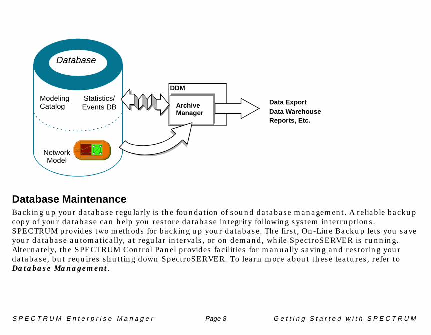
The SpectroSERVER DatabaseSPECTRUM collects a significant amount of information. Some information is collected as SPECTRUM polls network devices; some is collected from other SpectroSERVER management domains, called landscapes. This data is stored in the SpectroSERVER’s Events/Statistics database as events and statistics. Events record information such as changes to a device’s operational state, while statistics record data, such as total packets and total collisions. The Distributed Data Manager (DDM) provides facilities for reducing and saving the information gathered and distributing information in a variety of formats across multiple landscapes and to external applications.
DDM’s Archive Manager retrieves event and statistical data from the SpectroSERVER, reduces it, and stores it in the Events/Statistics database. Some overlap is maintained between the two databases to assure an accurate record of events and statistics in case of a system failure.
S P E C T R U M E n t e r p r i s e M a n a g e r Page 8 G e t t i n g S t a r t e d w i t h S P E C T R U M
Database MaintenanceBacking up your database regularly is the foundation of sound database management. A reliable backup copy of your database can help you restore database integrity following system interruptions. SPECTRUM provides two methods for backing up your database. The first, On-Line Backup lets you save your database automatically, at regular intervals, or on demand, while SpectroSERVER is running. Alternately, the SPECTRUM Control Panel provides facilities for manually saving and restoring your database, but requires shutting down SpectroSERVER. To learn more about these features, refer to Database Management.
Database
ModelingCatalog
NetworkModel
Events DBStatistics/ Data Export
Data WarehouseReports, Etc.
ArchiveManager
DDM

S P E C T R U M E n t e r p r i s e M a n a g e r Page 9 G e t t i n g S t a r t e d w i t h S P E C T R U M
Model Types, Models and Relations
The SpectroSERVER database provides storage for specific device configurations, statistics and events. The database also contains the Modeling Catalog (model types and relations) that determines the structure for all network information.
• Model types serve as templates. They define characteristics (attributes) of the elements that make up your network such as workstations, hubs, networks, and users. The modeling catalog contains model types that correspond to the device types found in your network. These device model types provide a template for device-specific information together with the Inference Handlers needed to help you manage your network.
• A Model represents a particular instance of a model type. Models are not part of the modeling catalog, but instead, they are created from the model types provided by the modeling catalog.
For example, to create a model of a particular SPARCstation 20™ workstation in your network (identified by a unique hostname and IP address), you would choose the Host_SUN model type as a template from the available model types in the modeling catalog. Before creating the model, SPECTRUM asks you to identify the particular workstation by supplying a unique IP address or hostname. This information uniquely identifies the new model as a particular SPARCstation 20.
Host_SUN
192.118.52.34
This model of the
model type, Host_SUN
is uniquely identified by the
IP address, 192.118.52.34.

S P E C T R U M E n t e r p r i s e M a n a g e r Page 10 G e t t i n g S t a r t e d w i t h S P E C T R U M
• Relations (Connects, Contains, Owns, etc.) define the relationships that can exist between two or more models. The type of relations that a particular model is capable of are determined by the model type used to create a model. For example, a model created from the Network model type can Contain a variety of network devices (routers, bridges, workstations, etc.) including specific network models such as FDDI_Networks, ATM_Networks, etc. Relations define the structure in your network model.
SPECTRUM IconsNetwork elements and organizational entities are represented in SPECTRUM’s views as icons. To the left are some of the icons you’ll find there. Icons alert you to network problems and provide access to a variety of configuration and information views. Each icon is unique to a particular model type.
Two models were created during SPECTRUM installation: a User model for the target user identified during installation and a VNM model that represents your SpectroSERVER. When you first start SPECTRUM, the VNM icon, is the only icon that is visible. The VNM icon provides access to views that can help you configure and manage SpectroSERVER functions. User models
determine who is allowed access to SPECTRUM. You’ll learn more about User models later in this book when you create User models for other users that will need to access SPECTRUM.
Relations establish the structure of your
network model allowing SPECTRUM to
correctly isolate problems.
This LAN_802_3 network
model contains a Host_SUN
workstation model.Host_SUN
192.118.52.34
LAN_802_3
Acctg_Subnet
LAN_802_3
Model Name
VNM
Fanout
Bridge
Off-Page Reference(Router)
Network (802.3)
Model Name
FANOUT
Model Type
Model Name
VNM
Model Name

S P E C T R U M E n t e r p r i s e M a n a g e r Page 11 G e t t i n g S t a r t e d w i t h S P E C T R U M
Icon Double-Click ZonesIcons are configured with “double-click” zones, areas that, when double-clicked using the mouse pointer, perform a specific action such as opening a view.
The Performance double-click zone is capable of plotting the performance of three device attributes, as shown here and throughout this book:
• Blue - Frame Rate• Green - Load• Orange - Error Rate
When SPECTRUM is first installed, the icon graphs are disabled (by default) and the Performance double-click zone is blank. (Refer to Getting Started with SPECTRUM for Operators to see an example of icons with graphs disabled.) You can enable icon graphs by setting the displayGraphOnIcons resource to true in the spectrum resource file in the app-defaults directory within the SPECTRUM install area or by highlighting the icon and selecting Show Performance Graph from the Icon Subviews menu.
LandscapesA landscape covers the management domain for a given SpectroSERVER. It includes a Topology, Location, and Organization model hierarchy. You can create your entire network model in a single landscape or divide it among several landscapes. SPECTRUM’s Distributed SpectroSERVER (DSS) feature allows you to manage multiple landscapes from the same SpectroGRAPH. Each landscape is identified by a unique landscape name. Refer to Distributed SpectroSERVER for detailed information about using the DSS feature.
Model Name
SNMP Device
SNMP
Typical Double-Click Zones
Opens Performance ViewOpens Performance View
Opens Application View
Opens Device View
Opens Device Topology
Opens Configuration View
(DevTop) View
(Generic SNMP Device Icon)
Performance double-click zone
Landscape
Model Name
4
1
7
4
1
7
S P E C T R U M E n t e r p r i s e M a n a g e r Page 12 G e t t i n g S t a r t e d w i t h S P E C T R U M
SPECTRUM Views
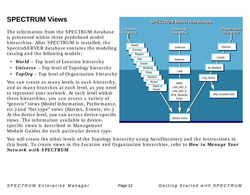
The information from the SPECTRUM database is presented within three predefined model hierarchies. After SPECTRUM is installed, the SpectroSERVER database contains the modeling catalog and the following models:
• World – Top level of Location hierarchy• Universe – Top level of Topology hierarchy• TopOrg – Top level of Organization hierarchy
You can create as many levels in each hierarchy, and as many branches at each level, as you need to represent your network. At each level within these hierarchies, you can access a variety of “generic” views (Model Information, Performance, etc.) and “list-type” views (Alarms, Events, etc.). At the device level, you can access device-specific views. The information available in device-specific views is described in Management Module Guides for each particular device type.
You will create the other levels of the Topology hierarchy using AutoDiscovery and the instructions in this book. To create views in the Location and Organization hierarchies, refer to How to Manage Your Network with SPECTRUM.
Device Icons
Any Location Icon
SPECTRUM Model Hierarchies
LocationHierarchy
TopologyHierarchy
OrganizationHierarchy
World
Country
Region
Site
Sector
Building
Floor
Section
Room
Rack orPanel
As Needed
Levels
Various
Org_Owns
Universe
Network
LAN
WAN
LAN_802_3
LAN_802_5
FDDI
SPECTRUM Model Hierarchies
LocationHierarchy
TopologyHierarchy
OrganizationHierarchy
ATM_Network
S P E C T R U M D i r e c t o r i e s a n d F i l e s
S P E C T R U M E n t e r p r i s e M a n a g e r Page 13 G e t t i n g S t a r t e d w i t h S P E C T R U M
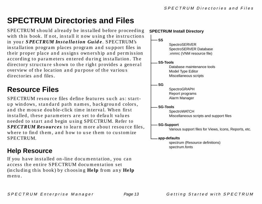
SPECTRUM Directories and FilesSPECTRUM should already be installed before proceeding with this book. If not, install it now using the instructions in your SPECTRUM Installation Guide. SPECTRUM’s installation program places program and support files in their proper place and assigns ownership and permission according to parameters entered during installation. The directory structure shown to the right provides a general overview of the location and purpose of the various directories and files.
Resource FilesSPECTRUM resource files define features such as: start-up windows, standard path names, background colors, and the mouse double-click time interval. When first installed, these parameters are set to default values needed to start and begin using SPECTRUM. Refer to SPECTRUM Resources to learn more about resource files, where to find them, and how to use them to customize SPECTRUM.
Help ResourceIf you have installed on-line documentation, you can access the entire SPECTRUM documentation set (including this book) by choosing Help from any Help menu.
SSSpectroSERVERSpectroSERVER Database.vnmrc (VNM resource file)
SS-ToolsDatabase maintenance toolsModel Type EditorMiscellaneous scripts
SGSpectroGRAPHReport programsAlarm Manager
SG-ToolsSpectroWATCHMiscellaneous scripts and support files
SG-SupportVarious support files for Views, Icons, Reports, etc.
app-defaultsspectrum (Resource definitions)spectrum.fonts
SPECTRUM Install Directory

T h e S P E C T R U M C o n t r o l P a n e l
S P E C T R U M E n t e r p r i s e M a n a g e r Page 14 G e t t i n g S t a r t e d w i t h S P E C T R U M
If you did not include documentation during your original installation, you can still access the documentation via the Documentation CD. Refer to your SPECTRUM Installation Guide to learn how to mount and access on-line documentation from the Documentation CD.
The SPECTRUM Control Panel
The Control Panel starts and stops SpectroSERVER, SpectroGRAPH and the Archive Manager. It also provides facilities for saving and restoring databases, for scheduling task execution, and configuring events, traps, resources.
To start the Control Panel:
1 Login to your workstation using the user ID that was defined for Target Ownership when starting the SPECTRUM installation.
login: < user ID>Password:

S P E C T R U M E n t e r p r i s e M a n a g e r Page 15 G e t t i n g S t a r t e d w i t h S P E C T R U M
2 Start the SPECTRUM Control Panel using one of the following formats:
The Select Host Machine dialog box appears, listing remote host machine names from which you can start the SPECTRUM Control Panel and run SPECTRUM.
3 Select a host machine name and click on OK. The Control Panel appears.
The panel is divided into three areas:
in UNIX in NT
Select SPECTRUM>Control Panel from the CDE Toolbar
Select Programs>Spectrum>Administration>Control Panel
Select Host to run on…
Select Host Machine
OK Exit
hostname #1
hostname #2
hostname #3
S P E C T R U M E n t e r p r i s e M a n a g e r Page 16 G e t t i n g S t a r t e d w i t h S P E C T R U M
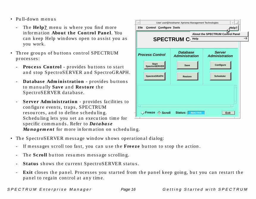
• Pull-down menus
- The Help? menu is where you find more information About the Control Panel. You can keep Help windows open to assist you as you work.
• Three groups of buttons control SPECTRUM processes:
- Process Control - provides buttons to start and stop SpectroSERVER and SpectroGRAPH.
- Database Administration - provides buttons to manually Save and Restore the SpectroSERVER database.
- Server Administration - provides facilities to configure events, traps, SPECTRUM resources, and to define scheduling. Scheduling lets you set an execution time for specific commands. Refer to Database Management for more information on scheduling.
• The SpectroSERVER message window shows operational dialog:
- If messages scroll too fast, you can use the Freeze button to stop the action.
- The Scroll button resumes message scrolling.
- Status shows the current SpectroSERVER status.
- Exit closes the panel. Processes you started from the panel keep going, but you can restart the panel to regain control at any time.
File Control C onfigure T ools Help?
Process ControlDatabase
AdministrationServer
Administration
SPECTRUM Control Panel
ExitFreeze Scroll Status: INACTIVE
Configure
SchedulerSpectroGRAPH
StartSpectroSERVER Save
Restore
User user@hostname: Aprisma Management Technologies
About the SPECTRUM Control Panel
Help

S t a r t i n g S P E C T R U M
S P E C T R U M E n t e r p r i s e M a n a g e r Page 17 G e t t i n g S t a r t e d w i t h S P E C T R U M
Starting SPECTRUM
Use the Control Panel to start SpectroSERVER and/or SpectroGRAPH. You can run both on the same workstation as described here, or you can use the Control Panel to start SpectroGRAPH on your local workstation and connect to a SpectroSERVER running on another workstation. SpectroSERVER must be running and ready to accept client connections before you start SpectroGRAPH. If you are connecting to a SpectroSERVER running on another workstation, bypass Starting SpectroSERVER and go to Starting SpectroGRAPH.
Starting SpectroSERVER:
Click on .
SpectroSERVER takes a short period of time to load. During this time the server message window displays several messages.
When SpectroSERVER is ready, the Control Panel displays a message indicating the server is ready, and the Status changes to RUNNING.
If you attempt to start SpectroGRAPH before SpectroSERVER is ready, an error message appears telling you: “No SpectroSERVER to talk to.”
ExitFreeze Scroll Status: RUNNING
Please wait. /usr/Spectrum/SS/SpectroSERVERlandscape 0x400000 at precedence 10...
Number of models loaded : 0
/usr/Spectrum/SS/SpectroSERVER is now ready on port 0xbeef...
is loading
StartSpectroSERVER

S P E C T R U M E n t e r p r i s e M a n a g e r Page 18 G e t t i n g S t a r t e d w i t h S P E C T R U M
Starting SpectroGRAPH:
1 Click on . The Select SpectroSERVER dialog box appears listing servers that you can connect to through SpectroGRAPH.
2 Select a host machine name and click on OK.
As SpectroGRAPH comes up, it displays the SPECTRUM logo. The default configuration tells SPECTRUM to open the highest Location view “SpectroGRAPH : Location : World” and the highest Topology view, “SpectroGRAPH : Topology : Universe.”
Since we are only modeling your network in the Topology hierarchy in this book, close the SpectroGRAPH : Location : World view. Pull down the File menu and choose Close.
Select SpectroSERVER
Select initial SpectroSERVER to connect to.
OK Exit
hostname #1
hostname #2
hostname #3
Available Servers:
0x0000000
0x00000000x0000000
SpectroGRAPH
File View Tools Bookmarks Help?
SpectroGRAPH : Topology : Universe
Topology View
Location View
File View Tools Bookmarks Help?
SpectroGRAPH : Location : World

M o d e l i n g Y o u r N e t w o r k
S P E C T R U M E n t e r p r i s e M a n a g e r Page 19 G e t t i n g S t a r t e d w i t h S P E C T R U M
Modeling Your Network
Initially, there are no models in the SPECTRUM database that correspond to devices on your network. The only models that exist in the beginning are the VNM representing your SpectroSERVER and a User model for the administrator who was identified during installation. You need to create a model of your network in the SpectroSERVER database, one that accurately represents your network and allows SPECTRUM to help you manage your network.
We will use AutoDiscovery, SPECTRUM’s automatic modeling feature to create a model of our network. You should model your own network following the same steps, but using your own devices and IP addresses.
For detailed information about other AutoDiscovery features, refer to the AutoDiscovery User’s Guide.
M a n u a l l y C r e a t i n g a D e v i c e M o d e l
S P E C T R U M E n t e r p r i s e M a n a g e r Page 20 G e t t i n g S t a r t e d w i t h S P E C T R U M
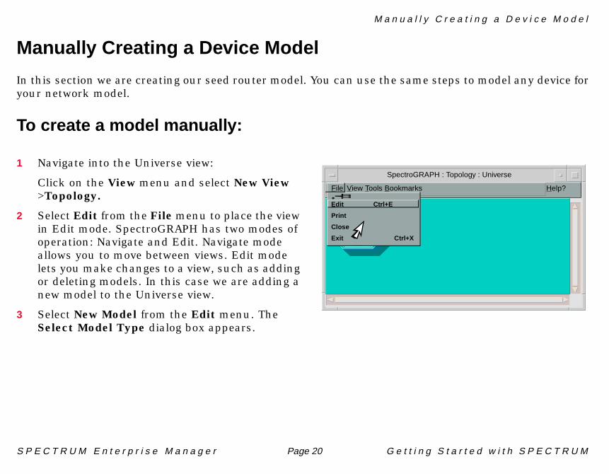
Manually Creating a Device Model
In this section we are creating our seed router model. You can use the same steps to model any device for your network model.
To create a model manually:
1 Navigate into the Universe view:
Click on the View menu and select New View >Topology.
2 Select Edit from the File menu to place the view in Edit mode. SpectroGRAPH has two modes of operation: Navigate and Edit. Navigate mode allows you to move between views. Edit mode lets you make changes to a view, such as adding or deleting models. In this case we are adding a new model to the Universe view.
3 Select New Model from the Edit menu. The Select Model Type dialog box appears.
File View Tools Bookmarks Help?
VNM
tutorEdit Ctrl+E
Close
Exit Ctrl+X
SpectroGRAPH : Topology : Universe

S P E C T R U M E n t e r p r i s e M a n a g e r Page 21 G e t t i n g S t a r t e d w i t h S P E C T R U M
4 Select a device model type from the Select Model Type dialog box and click OK.
In our example we are creating a Cisco router and have selected Rtr_Cisco. If your device is not in the list, it may be because SPECTRUM intelligence does not allow it to be modeled at that level in the hierarchy, or that there is no model type for that device. For basic SNMP manage-ment, you can model any device with the GnSNMPDev model type. For more detailed management, a specific model type is required.
A dialog box appears where you can define the specific model you are creating. Some of the fields are already defined by default. In addition to the default settings, a minimum definition requires an IP Address and Community String. Optional information, such as Contact, Location, etc. can be helpful in managing your network. You can enter the information here or add it later by editing the model’s Model Information view.
Note:Note:
Use the New Model by IP selection to create a model when you know the IP address of the device but not the model type. SPECTRUM interrogates the device to determine the model type and automatically creates a model, using the model type that most closely matches the actual device.
HelpEditFile
New Model…
New Model by IP…
Cut Shift +Del
Select Model Type
OK
Filter:
Cancel
Rtr_Bay_Wflet
Rtr_Cisco
Rtr_Cisco2500
Rtr_Cisco3000
Rtr_Cisco4000
Rtr_Cisco7000
Rtr_CiscoAGS
Rtr_Cisco CGS
Tools BookmarksSpectroGRAPH : Topology : Unive
Select Model Type
OK
Filter:
Cancel
Rtr_Bay_Wflet
Rtr_Cisco
Rtr_Cisco2500
Rtr_Cisco3000
Rtr_Cisco4000
Rtr_Cisco7000
Rtr_CiscoAGS
Rtr_Cisco_CGS
Rtr_Cisco_IGS

S P E C T R U M E n t e r p r i s e M a n a g e r Page 22 G e t t i n g S t a r t e d w i t h S P E C T R U M
5 Enter the appropriate information for your router.
Use the IP address of the router port closest to the SpectroSERVER workstation as the Network Address. This gives SPECTRUM some diagnostic capability even if the other router ports fail.
In our example, we’ve entered values that define the sample Router #1. Your router may be defined differently.
6 Click on OK. Your router model appears in the Universe view.
7 Leave the view in Edit mode and go on to the next module to learn how to use AutoDiscovery to model your network, or you can stop here by selecting File >Close Edit, and then File >Exit.
VNM
tutor
SpectroGRAPH
Creation View
Model Name Router #1
Network Address 132.177.2.1.
Community Name public
Serial Number 123456789
Security String
Polling Interval 60
Log Ratio 10
OK Cancel
Rtr_Cisco
Router #1
Shortly after your router is created,SPECTRUM establishes contact with itand the router icon’s label shouldchange from blue to green. Any othercolor indicates an alarm condition thatshould be fixed before you continue.
Discover Connections

A u t o D i s c o v e r y
S P E C T R U M E n t e r p r i s e M a n a g e r Page 23 G e t t i n g S t a r t e d w i t h S P E C T R U M
AutoDiscoveryAutoDiscovery is SPECTRUM’s automatic topology mapping facility. We’ll be using AutoDiscovery to find devices on the network and create corresponding models in the database. Begin by opening the main AutoDiscovery window.
Open the AutoDiscoveryWindow
Select Auto Discovery from the Tools menu at the Universe level. The main AutoDiscovery window opens.
AutoDiscovery offers three Discovery Methods:
• IP List maps a discovered device's IP address to a physical (MAC) address.When this method is used, AutoDiscovery will attempt to contact and identify only those devices at the IP addresses you specify when you create the configuration.

A u t o D i s c o v e r y
S P E C T R U M E n t e r p r i s e M a n a g e r Page 24 G e t t i n g S t a r t e d w i t h S P E C T R U M
• Range uses ICMP echo requests (pings) to test each of the IP addresses within the range or ranges you specify in the IP Address Ranges panel. When this method is used, AutoDiscovery will attempt to contact and identify devices at each IP address within the range(s) bounded by the pair(s) of low and high addresses you specify.
• Router examines the route tables in your network’s routers to establish the high-level topology of your network, creating subnets and LANs. Router discovery configurations require both a range of IP addresses (to establish the boundaries of the discovery) and one or more IP addresses for routers that AutoDiscovery will use as “seed” routers. The route information table and/or the routing neighbor tables of each seed router will then be queried to determine the addresses of neighboring routers. If these addresses are within the specified range, they too are queried, and the process is repeated until all known neighbors within the range(s) have been queried.
Both discovery and modeling operations are executed according to sets of user-specified guidelines called “configurations.” You create these reusable configurations via dialogs accessed from the AutoDiscovery main window’s Configurations menu. Once a configuration is saved, a corresponding entry is added to the appropriate folder in the main window’s Stored Configurations panel, where the configuration can then be accessed for modification, deletion, duplication, or execution.
There are three basic types of configurations:
• Discovery• Modeling• Discovery and Modeling.
AutoDiscovery’s modeling options determine how the discovery sessions will be conducted and how the resulting device models will be arranged in views in the Topology Hierarchy.
Note:Note:
AutoDiscovery is a very powerful, flexible, and customizable SPECTRUM application. The getting started procedures described in this document are intended as a quick overview/tutorial. For detailed instructions on using the complete functionality of AutoDiscovery, refer to the AutoDiscovery User’s Guide.

A u t o D i s c o v e r y
S P E C T R U M E n t e r p r i s e M a n a g e r Page 25 G e t t i n g S t a r t e d w i t h S P E C T R U M
Configuring Range Discovery
Range Discovery uses the range(s) of IP addresses you specify and attempts to contact and identify devices within this IP address range. It can be run on any range of addresses; however, the greater the range, the longer it takes to complete the search for devices. It is more efficient to make several entries, with each one defining limited ranges, than to search for one large range (e.g., an entire Class C address range). We will be using this discovery method in this tutorial.
1 Select Configurations>New Discover and Model Configurarion>Range/SPECTRUM from the AutoDiscovery main window. This option creates router and subnet models using information from routing tables and the IP Address Ranges table.
2 Determine the range of IP addresses that covers your network. For our example: 132.177.1.1 through 132.177.255.254.
3 In the IP Range Boundary List panel, define one or more ranges of IP addresses to establish the boundaries of the discovery by entering the lowest address in the range in the From field and the highest address in the To field. Then click the Add button to add the pair of addresses to the list. Use the Del (for “Delete”) and Mod (for “Modify”) buttons to remove or change any entries in the list. this configuration.
StartDuplicate
Export Configuration...Import Co
New Discovery Configuration
Configurations
New Discover and Model ConfigurationNew Modeling Configuration
nfiguration...
IP List / SPECTRUMRange / SPECTRUMRouter / SPECTRUM
From: To:
132.177.1.1 132.177.255.254
Community Strings
:
public
IP Range Boundary List
Del
Mod
Community String
Add132.177.1.1 132.177.255.254

A u t o D i s c o v e r y
S P E C T R U M E n t e r p r i s e M a n a g e r Page 26 G e t t i n g S t a r t e d w i t h S P E C T R U M
4 In the Community String List panel, specify the Community Strings (passwords) for the devices you want discovered. By default, AutoDiscovery will attempt to discover devices within the IP address boundaries you have specified if they have a Community String of “public.” You can enter additional strings one-at-a-time by typing in the text entry box and clicking Add.
Note:Note:
Enter community names ordered from “most used” to “least used.” Since AutoDiscovery searches using community names in the order (top to bottom) listed, placing the most widely used name at the top of the list can help optimize execution time.
To:
132.177.255.254
Community Strings
:
publicAdd
t
Del
Mod
Del
Mod
Community String
Addpublic
public
A u t o D i s c o v e r y
S P E C T R U M E n t e r p r i s e M a n a g e r Page 27 G e t t i n g S t a r t e d w i t h S P E C T R U M
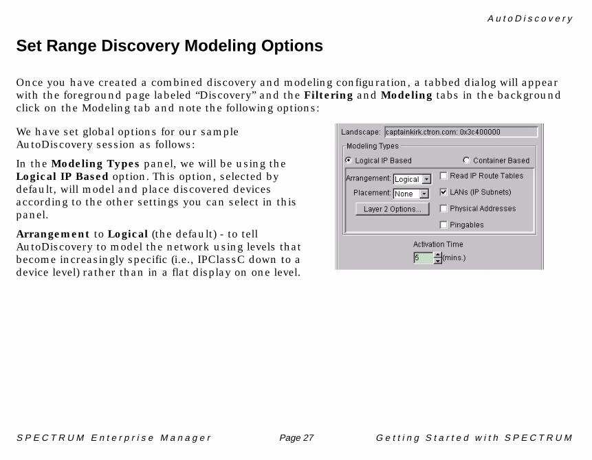
Set Range Discovery Modeling Options
Once you have created a combined discovery and modeling configuration, a tabbed dialog will appear with the foreground page labeled “Discovery” and the Filtering and Modeling tabs in the background click on the Modeling tab and note the following options:
We have set global options for our sample AutoDiscovery session as follows:
In the Modeling Types panel, we will be using the Logical IP Based option. This option, selected by default, will model and place discovered devices according to the other settings you can select in this panel.
Arrangement to Logical (the default) - to tell AutoDiscovery to model the network using levels that become increasingly specific (i.e., IPClassC down to a device level) rather than in a flat display on one level.
A u t o D i s c o v e r y
S P E C T R U M E n t e r p r i s e M a n a g e r Page 28 G e t t i n g S t a r t e d w i t h S P E C T R U M
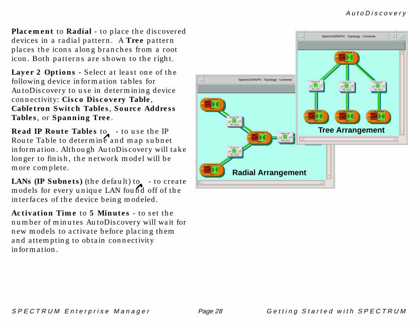
Placement to Radial - to place the discovered devices in a radial pattern. A Tree pattern places the icons along branches from a root icon. Both patterns are shown to the right.
Layer 2 Options - Select at least one of the following device information tables for AutoDiscovery to use in determining device connectivity: Cisco Discovery Table, Cabletron Switch Tables, Source Address Tables, or Spanning Tree.
Read IP Route Tables to �- to use the IP Route Table to determine and map subnet information. Although AutoDiscovery will take longer to finish, the network model will be more complete.
LANs (IP Subnets) (the default) to �- to create models for every unique LAN found off of the interfaces of the device being modeled.
Activation Time to 5 Minutes - to set the number of minutes AutoDiscovery will wait for new models to activate before placing them and attempting to obtain connectivity information.
Radial Arrangement
LAN
132.177.4.0
Rtr_Cisco
Router #3
LAN
132.177.3.0
LAN
132.177.2.0
LAN
132.177.1.0
Rtr_Cisco
Router #3
Rtr_Cisco
Router #3
SpectroGRAPH : Topology : Universe
Tree Arrangement
Rtr_Cisco
Router #2
LAN
132.177.3.0
LAN
132.177.2.0
LAN
132.177.4.0
Rtr_Cisco
Router #3
LAN
132.177.1.0
Rtr_Cisco
Router #1SpectroGRAPH : Topology : Universe

A u t o D i s c o v e r y
S P E C T R U M E n t e r p r i s e M a n a g e r Page 29 G e t t i n g S t a r t e d w i t h S P E C T R U M
Start the Discover and Model Session
Click on Save & Start in the main AutoDiscovery window.
You will be prompted to specify a name for this AutoDiscovery configuration. Since you may be using the same address range and community names in a future AutoDiscovery session, this configuration will be automatically saved and stored under Discover & Model Configuration in the Stored Configurations panel.
Each time you start a discovery session, a “result set” is automatically created to store:
• the configuration that was used• status and error messages generated during the session• a list of all discovered devices called the “discovered data set”
The “discovered data set” is the exportable part of the result set and the main input for subsequent modeling in SPECTRUM. It catalogs all the devices that were discovered and provides location, contact, port, and other information as applicable.
Creation of a new result set has two effects on the AutoDiscovery main window, as shown in the following figure. First, a new entry is added to the scrollable Results list at the lower left of the window. Each entry in this list uniquely identifies a particular result set by the name of the configuration that was used plus the date and time the session was started. The entry also shows the current status of the session. Secondly, a Results view with tabbed pages displays in the large panel at the right of the window.
As devices are discovered, they are listed by IP address under the Results tab. Status or error messages generated during the discovery appear at the bottom of this tabbed page.
Save CancelSave & Start

A u t o D i s c o v e r y
S P E C T R U M E n t e r p r i s e M a n a g e r Page 30 G e t t i n g S t a r t e d w i t h S P E C T R U M
The Discovery tab accesses the associated discovery configuration. The Results view also includes a Modeling tab, which accesses the associated modeling configuration.
Results listshowing entryfor result setdisplayed inResults dialog
Results dialogwith tabs foraccessingassociateddiscovery andmodelingconfigurations

A u t o D i s c o v e r y
S P E C T R U M E n t e r p r i s e M a n a g e r Page 31 G e t t i n g S t a r t e d w i t h S P E C T R U M
Here’s What We’ve DiscoveredIn our example, an IPClassB network model has been modeled in the Universe Topology view.
Two LAN models have been created in the IPClassB network model connected by a router model.
In one of the LAN models, there is an Off-Page Reference icon representing the connected router, an Unplaced Fanout model containing device models that AutoDiscovey was not able to resolve, and a LAN_802_3 model representing a local area network.
In the LAN_802_3 model, there are two workstation models connected to a hub model.
SpectroGRAPH : Topology : Universe
IPClassB
132.177.0.0
SpectroGRAPH : Topology : 132.177.0.0
LAN
132.177.1.0
Rtr_Cisco
Router #1
LAN
132.177.2.0
SpectroGRAPH : Topology : 132.177.2.0
UnplacedRouter #1
tutor
VNM
LAN_802_3
SpectroGRAPH : Topology : 132.177.2.0
Workstation #2Workstation #1 Hub #1

R e a d i n g t h e I n f o r m a t i o n i n S P E C T R U M V i e w s
S P E C T R U M E n t e r p r i s e M a n a g e r Page 32 G e t t i n g S t a r t e d w i t h S P E C T R U M
Reading the Information in SPECTRUM ViewsIcons use colors to visually convey status showing a model’s Condition and Rollup Condition. A model’s Condition color alerts you to problems with the model. Rollup Condition indicates the status of models at lower levels of the hierarchy. As the SPECTRUM administrator, you can set the thresholds for Rollup Condition colors based on the severity of the condition of models at the next lower level in the hierarchy.
For example, the rollup threshold for a LAN model might be set to show a Red rollup condition when two or more devices within it have a Red condition.
Color Condition Meaning
Green Good - Contact established/Normal operation
Yellow Minor Alarm - A situation has occurred but no immediate action is required. This condition is also used for alarmscreated only to convey information, such as “Duplicate IP.”
Orange Major Alarm - A loss of service has occurred or is impending. Action is required within a short period of time.
Red Critical - A loss of service has occurred and immediate action is required.
Gray Unknown - This device cannot be reached due to a known error condition that exists on another device.
Blue Initial - Contact with this device has not yet been established.
Brown Device has been taken off-line for maintenance purposes.
Location Network A
CSIRptr
FANOUT
Condition Color Zones - Condition of this model
Rollup Condition Color Zones - composite status of models beneath this one.

P i p e s - L o g i c a l L i n k s B e t w e e n I c o n s
S P E C T R U M E n t e r p r i s e M a n a g e r Page 33 G e t t i n g S t a r t e d w i t h S P E C T R U M
Pipes - Logical Links Between Icons
Network connections are collectively represented as logical links called “pipes.” A pipe can represent many port-to-port connections. Pipes are created automatically when you create your network model using SPECTRUM’s AutoDiscovery feature, described earlier in this guide. Pipes can be configured as Standard pipes or Live pipes. (Standard Pipes is the default configuration setting.)
Standard PipesTwo types of standard pipes can be created to show connections:
Gold pipes show connections that are resolved (connected to an actual port at both ends). AutoDiscovery always resolves connections to a device port, producing gold pipes. Gold pipes cannot be erased from SPECTRUM views.
Silver pipes are manually created by selecting two icons and choosing the Connect selection from the Edit menu and or by using the mouse to draw a connection between icons while in Edit mode. If the connection represented by a silver pipe cannot be resolved, the pipe remains silver. However, if the connection is resolved, the pipe automatically turns to gold. Silver pipes can be erased.
132.177.0.0 of type IPClassB of Landscape tutor: Primary
LAN
132.177.1.0
Rtr_Cisco
Router #1
FANOUT
Silver Pipe Gold Pipe
File View Tools Bookmarks Help?

S P E C T R U M E n t e r p r i s e M a n a g e r Page 34 G e t t i n g S t a r t e d w i t h S P E C T R U M
Live PipesWhen SPECTRUM’s Live Pipes feature is enabled (from the VNM model’s Landscape Configuration view), individual pipes can be toggled from Standard to Live by choosing the Enable Live Pipes selection from a pipe’s Icon Subviews menu and then clicking on the button in the Enable Live Links dialog box. For additionalinformation on live pipes, refer to Distributed SpectroSERVER and SPECTRUM Icons.
Live pipes use colors to provide additional status information. Within a live pipe, the connection having the most severe condition (bad, disabled, etc.) determines the pipe’s color. A live pipe can generate an alarm when one of the links that it represents goes down.
LAN
132.177.1.0
Rtr_Cisco
Router #1
pcA_1: port1 <-> Hub4: port 11
Enable Live Links
Listed below is the set of links/port-pairs this pipe representsand a toggle indicating if the link is “Live”.
Enabling a link will cause the pipe to display a combination ofall the live links’ conditions and cause alarms to be generated forthe live links.
OK Cancel
CloseNavigate
Utilities
AlarmsPerformanceNotes
ZoomLink InformationEnable Live Links…

S P E C T R U M E n t e r p r i s e M a n a g e r Page 35 G e t t i n g S t a r t e d w i t h S P E C T R U M
The condition of the individual connections within a pipe is based on the condition of the ports at either end of a connection. For example, if one port is bad and the other is good the connection has a red condition, and since red is the most severe condition, the pipe will also be red. The matrix below shows the possible port condition combinations and the resulting pipe colors.
The initial color of a pipe is blue, indicating an unresolved link (contact not yet established). Once the link is resolved, the pipe displays a color as listed below.
Pipes are automatically re-created whenever a pair of previously-piped icons are placed in the same view. This means, if you remove (cut, destroy, erase) either or both icons of a piped pair, the pipe is erased. Later, if you place both previously-piped icons in a view, the pipe connecting them will reappear in the view.
132.177.0.0 of type IPClassB of Landscape tutor: Primary
Unresolved Link (Blue)
Good Link
Unreachable Link (Gray)
LAN
132.177.1.0
FANOUT
Rtr_Cisco
Router #1
LAN
132.177.1.0(Green)
File View Tools Bookmarks Help?

S P E C T R U M E n t e r p r i s e M a n a g e r Page 36 G e t t i n g S t a r t e d w i t h S P E C T R U M
Port Conditions and Live Pipe Colors
Local Port
PORT CONDITION Good Bad Unknown Disabled Unreachable
RemotePort
Good GREEN
Bad RED RED
Unknown GREEN RED GREEN
Disabled BROWN BROWN BROWN BROWN
Unreachable GRAY GRAY GRAY BROWN GRAY
S P E C T R U M E n t e r p r i s e M a n a g e r Page 37 G e t t i n g S t a r t e d w i t h S P E C T R U M
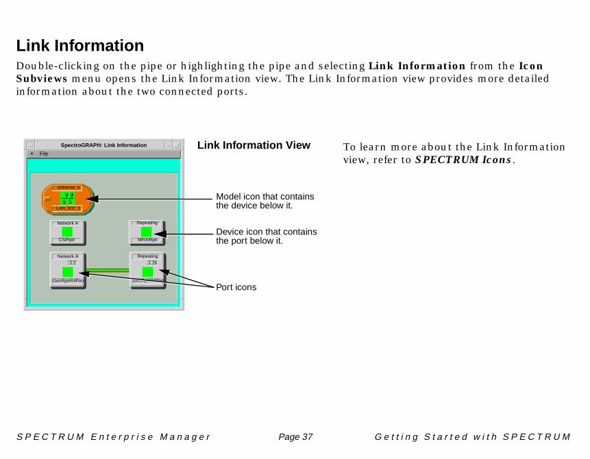
Link InformationDouble-clicking on the pipe or highlighting the pipe and selecting Link Information from the Icon Subviews menu opens the Link Information view. The Link Information view provides more detailed information about the two connected ports.
To learn more about the Link Information view, refer to SPECTRUM Icons.
File*SpectroGRAPH: Link Information
Universe_6
LAN_802_3
Network A
CSIRptr
Repeating
MRXiRptr
Network A
GenRptrR4Port
2.2
Repeating
GenRptrR4Port
1.26
Link Information View
Port icons
Device icon that contains
Model icon that containsthe device below it.
the port below it.

C r e a t i n g U s e r M o d e l s
S P E C T R U M E n t e r p r i s e M a n a g e r Page 38 G e t t i n g S t a r t e d w i t h S P E C T R U M
Creating User Models
User models determine who can access SPECTRUM. Minimally, they define each user by user ID and access privileges, but additional attributes, such as location, organization, and graphic image of the user can also be recorded. Only users having a User model in a SpectroSERVER’s database are permitted access to that SpectroSERVER’s landscape, views, and data. If you specified a user name (Target Ownership) during your SPECTRUM installation, a User model was automatically created for that user ID. If other users will need access, you must create User models for them with SPECTRUM’s User Editor.
As the Administrator of your network, you can set specific access privileges for each User model that you add to the database. The Community String entered for each user determines the level of access. The default Community String, ADMIN,0, grants unrestricted administrative privileges. Security implementation is beyond the scope of this book, so we are not going to implement a Community String that restricts access. To learn how to apply security, refer to Security and User Maintenance.

S P E C T R U M E n t e r p r i s e M a n a g e r Page 39 G e t t i n g S t a r t e d w i t h S P E C T R U M
To create a User model:
1 Navigate into the Universe Topology view.
2 Double-click on the user symbol on the right side of the VNM icon or highlight the icon and select User Editor from the Iocn Subviews menu.
The UserEditor window appears.

S P E C T R U M E n t e r p r i s e M a n a g e r Page 40 G e t t i n g S t a r t e d w i t h S P E C T R U M
3 Double-click on the Landscape icon in the tree area (left side).
4 Click on the New User button. The Create new User dialog box appears.
5 Enter the user ID for the User model being created and click OK.
The new User model is added to the landscape.
UserEditor: Create new User
Enter the name for User:
Cancel
nancynetwatcher
OK Clear
Net_Admin
Corporate_Landscape
nancynetwatcher
S P E C T R U M E n t e r p r i s e M a n a g e r Page 41 G e t t i n g S t a r t e d w i t h S P E C T R U M
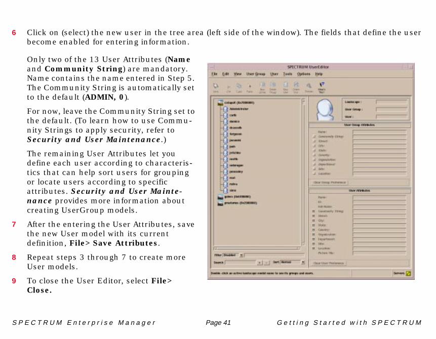
6 Click on (select) the new user in the tree area (left side of the window). The fields that define the user become enabled for entering information.
Only two of the 13 User Attributes (Name and Community String) are mandatory. Name contains the name entered in Step 5. The Community String is automatically set to the default (ADMIN, 0).
For now, leave the Community String set to the default. (To learn how to use Commu-nity Strings to apply security, refer to Security and User Maintenance.)
The remaining User Attributes let you define each user according to characteris-tics that can help sort users for grouping or locate users according to specific attributes. Security and User Mainte-nance provides more information about creating UserGroup models.
7 After the entering the User Attributes, save the new User model with its current definition, File> Save Attributes.
8 Repeat steps 3 through 7 to create more User models.
9 To close the User Editor, select File> Close.
E x i t i n g S P E C T R U M
S P E C T R U M E n t e r p r i s e M a n a g e r Page 42 G e t t i n g S t a r t e d w i t h S P E C T R U M
Exiting SPECTRUM
Now that you have created a model of your network and added the appropriate users to the SpectroSERVER database, you have completed all the tasks outlined at the beginning of this book, except stopping SpectroSERVER and SpectroGRAPH.
At this point, you can exit from SPECTRUM and the Control Panel or continue exploring SPECTRUM’s views and exit later using the following procedure. SpectroGRAPH, SpectroSERVER, and the Control Panel were started as separate processes and must be stopped as separate processes.
To Stop SpectroGRAPH:
Select File > Exit from the menu bar in any of the SPECTRUM views. All the views will close and SpectroGRAPH will stop.
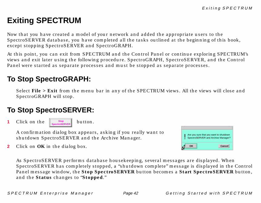
To Stop SpectroSERVER:
1 Click on the button.
A confirmation dialog box appears, asking if you really want to shutdown SpectroSERVER and the Archive Manager.
2 Click on OK in the dialog box.
As SpectroSERVER performs database housekeeping, several messages are displayed. When SpectroSERVER has completely stopped, a “shutdown complete” message is displayed in the Control Panel message window, the Stop SpectroSERVER button becomes a Start SpectroSERVER button, and the Status changes to “Stopped.”
Are you sure that you want to shutdown
OK Cancel
SpectroSERVER and Archive Manager?!
StopSpectroSERVER

W h a t N e x t ?
S P E C T R U M E n t e r p r i s e M a n a g e r Page 43 G e t t i n g S t a r t e d w i t h S P E C T R U M
To Exit from the Control Panel:
1 Click on the Exit button to exit from the Control Panel.
A confirmation dialog box appears.
2 Click on OK.
What Next?You have now modeled your network with SPECTRUM and are ready to use it to manage your network. We recommend reading How to Manage Your Network With SPECTRUM to learn how to optimize management with SPECTRUM through customizing and maintaining your network model, monitoring and isolating alarms, and troubleshooting.
Are you sure you wish to exit the SPECTRUM
OK Cancel
Control Panel?!
L e a r n i n g M o r e A b o u t S P E C T R U M …
S P E C T R U M E n t e r p r i s e M a n a g e r Page 44 G e t t i n g S t a r t e d w i t h S P E C T R U M
Learning More About SPECTRUM …
For further reference, SPECTRUM documentation is your best source for current information. The Software Release Notice (SRN) that came with your copy of SPECTRUM lists titles and part numbers for the latest documentation and provides timesaving information on known anomalies. If you installed SPECTRUM Documentation during install or provided access as described earlier (refer to “Help Resource” on page 13), you can access SPECTRUM documents by choosing Help from the Help menu in any SPECTRUM view.
Four categories of SPECTRUM products are available:
• End User Products – these are the SPECTRUM Network Management core products, including:
- SpectroGRAPH, the SPECTRUM User Interface (UI)- SpectroSERVER, the network management software- Core management modules and applications
• Level I Toolkits – these provide the capability to add support for additional devices and to enhance or modify aspects of SPECTRUM core without writing any C++ code.
• Level II Toolkits – these offer programming interfaces for the purpose of developing C++ advanced extensions to SPECTRUM. These toolkits include header files, object libraries, example source code, and complete documentation.
• Applications – these are products designed to complement SPECTRUM End User Products. This category of products includes applications such as SpectroWATCH, SPECTRUM Data Gateway, SPECTRUM AR System Gateway, SPECTRUM NetView® Gateway, SPECTRUM Report Generator, and SPECTRUM Data Export.