applications & gateways - ca...
TRANSCRIPT
Transmission Applications
Applications & Gateways
Titlep
age
D e v i c e M a n a g e m e n t Page 2 T r a n s m i s s i o n A p p l i c a t i o n s
Copyright NoticeDocument 5064. Copyright © 2002-present by Aprisma Management Technologies, Inc. All rights reserved worldwide. Use, duplication, or disclosure by the United States government is subject to the restrictions set forth in DFARS 252.227-7013(c)(1)(ii) and FAR 52.227-19.Liability DisclaimerAprisma Management Technologies, Inc. (“Aprisma”) reserves the right to make changes in specifications and other information contained in this document without prior notice. In all cases, the reader should contact Aprisma to inquire if any changes have been made.
The hardware, firmware, or software described in this manual is subject to change without notice.
IN NO EVENT SHALL APRISMA, ITS EMPLOYEES, OFFICERS, DIRECTORS, AGENTS, OR AFFILIATES BE LIABLE FOR ANY INCIDENTAL, INDIRECT, SPECIAL, OR CONSEQUENTIAL DAMAGES WHATSOEVER (INCLUDING BUT NOT LIMITED TO LOST PROFITS) ARISING OUT OF OR RELATED TO THIS MANUAL OR THE INFORMATION CONTAINED IN IT, EVEN IF APRISMA HAS BEEN ADVISED OF, HAS KNOWN, OR SHOULD HAVE KNOWN, THE POSSIBILITY OF SUCH DAMAGES.
Trademark, Service Mark, and Logo InformationSPECTRUM, IMT, and the SPECTRUM IMT/VNM logo are registered trademarks of Aprisma Management Technologies, Inc., or its affiliates. APRISMA, APRISMA MANAGEMENT TECHNOLOGIES, the APRISMA MANAGEMENT TECHNOLOGIES logo, MANAGE WHAT MATTERS, DCM, VNM, SpectroGRAPH, SpectroSERVER, Inductive Modeling Technology, Device Communications Manager, SPECTRUM Security Manager, and Virtual Network Machine are unregistered trademarks of Aprisma Management Technologies, Inc., or its affiliates. For a complete list of Aprisma trademarks, service marks, and trade names, go tohttp://www.aprisma.com/manuals/trademark-list.htm.
All referenced trademarks, service marks, and trade names identified in this document, whether registered or unregistered, are the intellectual property of their respective owners. No rights are granted by Aprisma Management Technologies, Inc., to use such marks, whether by implication, estoppel, or otherwise. If you have comments or concerns
about trademark or copyright references, please send an e-mail to [email protected]; we will do our best to help.
Restricted Rights Notice(Applicable to licenses to the United States government only.)This software and/or user documentation is/are provided with RESTRICTED AND LIMITED RIGHTS. Use, duplication, or disclosure by the government is subject to restrictions as set forth in FAR 52.227-14 (June 1987) Alternate III(g)(3) (June 1987), FAR 52.227-19 (June 1987), or DFARS 52.227-7013(c)(1)(ii) (June 1988), and/or in similar or successor clauses in the FAR or DFARS, or in the DOD or NASA FAR Supplement, as applicable. Contractor/manufacturer is Aprisma Management Technologies, Inc. In the event the government seeks to obtain the software pursuant to standard commercial practice, this software agreement, instead of the noted regulatory clauses, shall control the terms of the government's license.Virus DisclaimerAprisma makes no representations or warranties to the effect that the licensed software is virus-free.
Aprisma has tested its software with current virus-checking technologies. However, because no antivirus system is 100 percent effective, we strongly recommend that you write-protect the licensed software and verify (with an antivirus system in which you have confidence) that the licensed software, prior to installation, is virus-free.
Contact InformationAprisma Management Technologies, Inc.273 Corporate DrivePortsmouth, NH 03801Phone: 603-334-2100U.S. toll-free: 877-468-1448Web site: http://www.aprisma.com

D e v i c e M a n a g e m e n t Page 3 T r a n s m i s s i o n A p p l i c a t i o n s
ContentsINTRODUCTION 6
Purpose and Scope ........................................................6Other Applications Documents .......................................6Summary of This Document ...........................................7
FDDI APPLICATIONS 8
FddiSMT Application.......................................................8FDDI Station List View.................................................8
FDDI App (RFC 1512App) ............................................10SMT Device Configuration View................................10
Station Table..........................................................10MAC Table .............................................................14
POINT-TO-POINT APPLICATION 18
PPP LCP Application Configuration View .....................18PPP LCP Configuration View ....................................19
PPP Link Status Configuration View - Local to Remote Configuration Table................................................19
PPP Link Status Configuration Table View - Remote to Local Configuration View .......................................20
PPP Link Status Table View .........................................21
DS1 APPLICATION 23
DS1App1406 Application ..............................................23DS1 Configuration Table ...........................................23DS1 Fractional Table.................................................28
DS1App1406 Current Table View ............................. 28
DS3 APPLICATION (DS3APP1407) 30
DS3/E3 Configuration Table ......................................... 30DS3/E3 Current Table................................................... 32DS3/E3 Interval Table................................................... 33DS3/E3 Total Table....................................................... 34
RS-232 APPLICATION 35
RS-232 Application Views............................................. 35RS-232 Port Table View............................................ 35
RS-232 Port Table Configuration View.................. 36RS-232 Port Input Signals Table View............... 36RS-232 Port Output Signals Table View ............ 37
RS-232 Synchronous Views ......................................... 38RS-232 Synchronous Port Table View...................... 38
Synchronous Port Table Detail View ..................... 39RS-232 Asynchronous Views ....................................... 39
RS-232 Asynchronous Port Table View .................... 40RS-232 Asynchronous Port Detail View ................ 41
WAN APPLICATION 42
WAN Connection Table View........................................ 42WAN Connection Physical Ports View ...................... 43
WAN Connection Interface Table View ................. 44

C o n t e n t s C o n t e n t s
D e v i c e M a n a g e m e n t Page 4 T r a n s m i s s i o n A p p l i c a t i o n s
FRAME RELAY APPLICATION 45
Virtual Circuit Table View..............................................45Circuit Error Table View ................................................46Interface Dlcmi Table View ...........................................47
TOKEN RING APPLICATION 49
Token Ring Application .................................................49Token Ring Detail View .............................................49
Token Ring IF Views.....................................................51Token Ring IF Configuration View.............................51
ETHERNET APPLICATION 53
Ethernet Application Detail View...................................53Transmit Success Counts..........................................53Frame Errors .............................................................53Transmit Fail Errors ...................................................54
Ethernet Application Configuration View.......................54
802DOT11APPLICATION 55
Station Configuration Table View..................................55Authentication Algorithms Table View ..........................58Counters Table View.....................................................58Group Address Table View ...........................................60Operation Table View ...................................................60Antenna List Table View ...............................................62Physical Antenna Table View .......................................62Physical DSSS Entry Table View..................................63Physical FHSS Table View ...........................................63PhyIR Table View .........................................................64
Physical Operation Table View .................................... 65Physical Transmission Power Table View.................... 65Privacy Table View....................................................... 66Regulatory Domains Supported Table View ................ 66Supported Data Rate Rx Table View ........................... 67Supported Data Rate Tx Table View............................ 67WEP Default Keys Table View ..................................... 67WEP Key Mappings Table View................................... 67Resource Information Table View ................................ 68
RFC1315 FRAME RELAY APPLICATION 69
rfc1315App Error Table ................................................ 69rfc1315App Data Link Connection Management Table 69rfc1315App Circuit Table.............................................. 71
Create a Circuit Entry ............................................ 72
RFC1285 APPLICATION 73
FDDI SMT Information ................................................. 73FDDI MAC Group ......................................................... 75FDDI Port Information .................................................. 78FDDI Attachment Information....................................... 81
SONET APPLICATION 82
SONET Medium Table View ........................................ 82SONET Section Current Table View ............................ 83SONET Section Interval Table View ............................ 84SONET Line Current Table View ................................. 85SONET Line Interval Table .......................................... 86SONET Far End Line Current Table View.................... 86
C o n t e n t s C o n t e n t s
D e v i c e M a n a g e m e n t Page 5 T r a n s m i s s i o n A p p l i c a t i o n s
SONET Far End Line Interval Table .............................87SONET Path Current Table View .................................88SONET Path Interval Table View..................................89SONET Far End Path Current Table View....................89SONET Far End Path Interval Table View....................90SONET Virtual Tributary Current Table View................90SONET Virtual Tributary Interval Table View................91SONET Far End Virtual Tributary Current Table View..92SONET Far End Virtual Tributary Interval Table View..92
RFC2115APP 94
rfc2115App Views .........................................................94Frame Relay Circuit Table.........................................95Frame Relay Data Link Connection Management Table
98Frame Relay Error Table .........................................100
RFC2667APP 103
RFC2667App ..............................................................103Tunnel Interface Table.............................................103Tunnel Configuration Table .....................................105
INDEX 106

D e v i c e M a n a g e m e n t Page 6 T r a n s m i s s i o n A p p l i c a t i o n s
Introduction
This section summarizes the contents of this document, which is one of a set of documents describing SPECTRUM applications. This section also provides references to the other applications documents.
This section covers the following topics:
• Purpose and Scope
• Other Applications Documents
• Summary of This Document (Page 7)
Purpose and ScopeThis document defines the fields displayed in the views associated with a category of SPECTRUM applications called transmission applications, which includes such applications as FDDI, Token Ring, and Ethernet. In all cases, the views and fields described in this document are accessed from the Icon Subviews menu of the application models displayed in the Main Applications view.
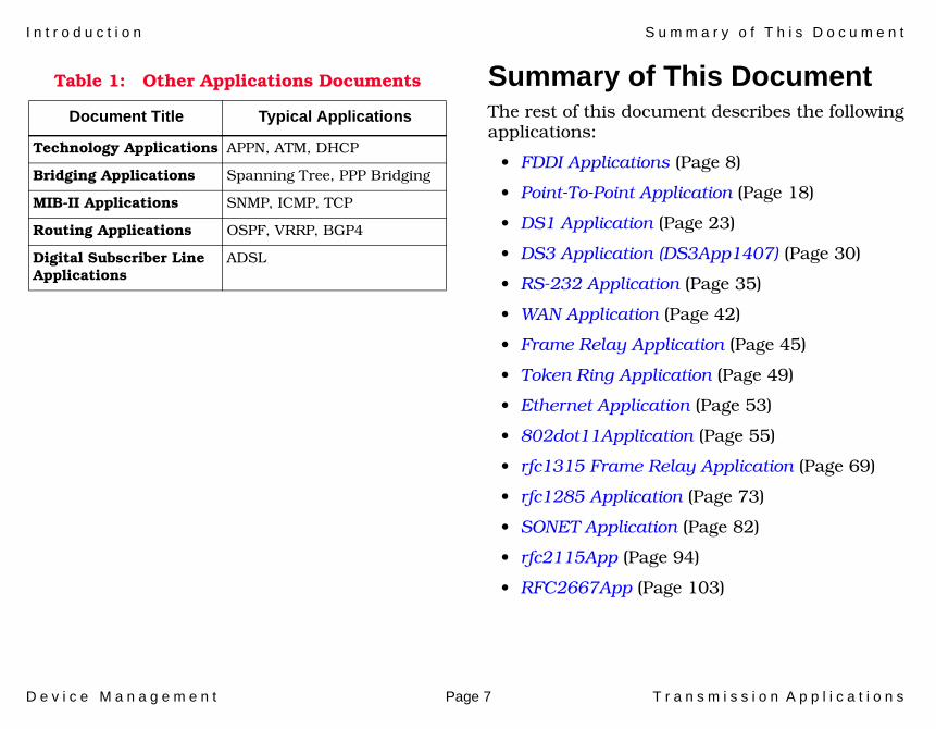
Other Applications DocumentsTable 1 lists the documents that cover the other categories of SPECTRUM applications. In addition to the documents listed in the table, the document Application View and MIBs provides an introduction to the Application view and defines MIB functions in network management. All of these documents (and others) are available on the Aprisma Web site at:
www.aprisma.com/manuals/
I n t r o d u c t i o n S u m m a r y o f T h i s D o c u m e n t
D e v i c e M a n a g e m e n t Page 7 T r a n s m i s s i o n A p p l i c a t i o n s
Summary of This DocumentThe rest of this document describes the following applications:
• FDDI Applications (Page 8)
• Point-To-Point Application (Page 18)
• DS1 Application (Page 23)
• DS3 Application (DS3App1407) (Page 30)
• RS-232 Application (Page 35)
• WAN Application (Page 42)
• Frame Relay Application (Page 45)
• Token Ring Application (Page 49)
• Ethernet Application (Page 53)
• 802dot11Application (Page 55)
• rfc1315 Frame Relay Application (Page 69)
• rfc1285 Application (Page 73)
• SONET Application (Page 82)
• rfc2115App (Page 94)
• RFC2667App (Page 103)
Table 1: Other Applications Documents
Document Title Typical Applications
Technology Applications APPN, ATM, DHCP
Bridging Applications Spanning Tree, PPP Bridging
MIB-II Applications SNMP, ICMP, TCP
Routing Applications OSPF, VRRP, BGP4
Digital Subscriber Line Applications
ADSL

D e v i c e M a n a g e m e n t Page 8 T r a n s m i s s i o n A p p l i c a t i o n s
FDDI Applications
FDDI provides speed and reliability to a LAN and is often used as a backbone technology as well as a means of connecting high-speed computers in a local area. This section describes the views available for the FDDI application.
There are two FDDI Applications:
• FddiSMT Application • FDDI App (RFC 1512App) (Page 10)
FddiSMT ApplicationThere is one application-specific subview available for the FddiSMT application from the FddiSMT Icon Subviews menu, the FDDI Station List View. This view displays the configuration of the FDDI ring and basic information about the devices in the ring.
FDDI Station List ViewAccess: From the Icon Subviews menu for the FddiSMTApp Application icon, select Station List.
The FDDI Station List View displays the configuration of the FDDI ring and basic information about the devices in the ring.
Station AddressThe address of the ring node. You select canonical or MAC presentation.
Node ClassThe type of FDDI ring device. Table 2 displays possible Node Class values.

F D D I A p p l i c a t i o n s F d d i S M T A p p l i c a t i o n
D e v i c e M a n a g e m e n t Page 9 T r a n s m i s s i o n A p p l i c a t i o n s
Ring TopologyThe current state of this FDDI node.
Master PortsThe number of master ports on this node. Values range from 0 to 255.
Upstream NeighborThe canonical or MAC address of the last node to receive the token before this node. SMT Rev 6.2 and earlier will specify an unknown address as 00.00.00.00.00.00. SMT revisions after 6.2 will specify an unknown address as 00.00.F8.00.00.00.
Click on this button to update the table.
Click on this button to toggle the display of station addresses between MAC (Physical) and Canonical (Ethernet). The button displays the format NOT currently selected.
Click on this button to set a filter affecting the stations displayed in the table. Choices are Set Filter and Clear Filter. Select an attribute to filter against by clicking one of the column heading buttons.
Click on this button to sort the stations displayed in the table. Values are Sort Up (default), Sort Down, and Un-Sort. To select an attribute to sort, click one of the column heading buttons.
Table 2: Node Class Values
Value Definitions
Station An FDDI node capable of receiving, transmitting, and repeating data.
Concentrator An FDDI node that provides attachment points for stations that are not directly connected to the FDDI ring.
Update
MAC/Canonical
Set/Clear Filter
Sort/Up
F D D I A p p l i c a t i o n s F D D I A p p ( R F C 1 5 1 2 A p p )
D e v i c e M a n a g e m e n t Page 10 T r a n s m i s s i o n A p p l i c a t i o n s
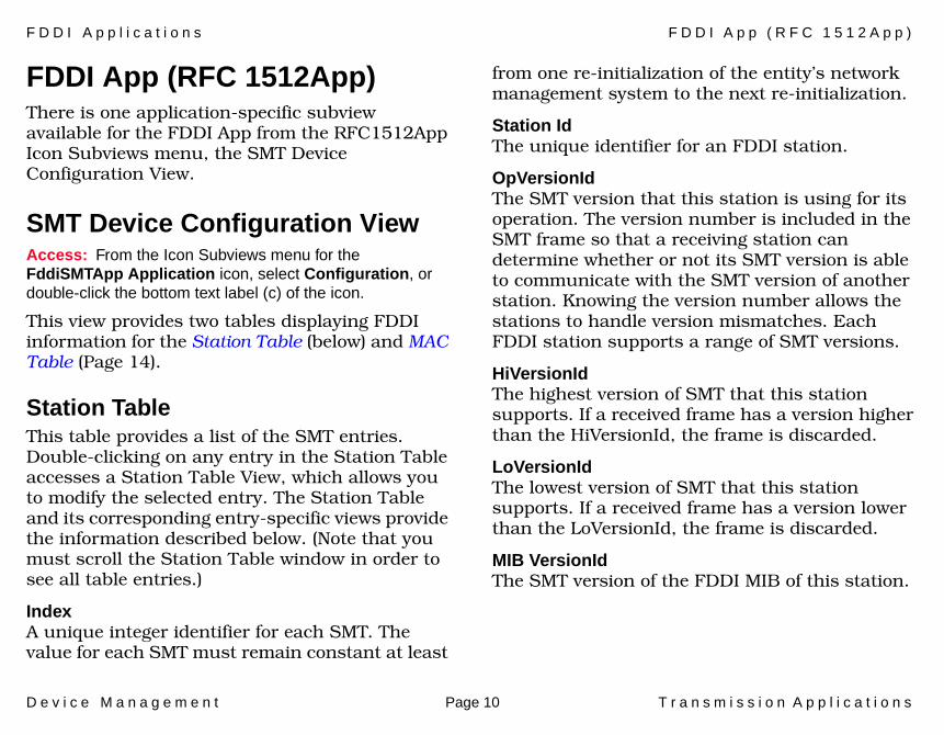
FDDI App (RFC 1512App)There is one application-specific subview available for the FDDI App from the RFC1512App Icon Subviews menu, the SMT Device Configuration View.
SMT Device Configuration ViewAccess: From the Icon Subviews menu for the FddiSMTApp Application icon, select Configuration, or double-click the bottom text label (c) of the icon.
This view provides two tables displaying FDDI information for the Station Table (below) and MAC Table (Page 14).
Station TableThis table provides a list of the SMT entries. Double-clicking on any entry in the Station Table accesses a Station Table View, which allows you to modify the selected entry. The Station Table and its corresponding entry-specific views provide the information described below. (Note that you must scroll the Station Table window in order to see all table entries.)
IndexA unique integer identifier for each SMT. The value for each SMT must remain constant at least
from one re-initialization of the entity’s network management system to the next re-initialization.
Station IdThe unique identifier for an FDDI station.
OpVersionIdThe SMT version that this station is using for its operation. The version number is included in the SMT frame so that a receiving station can determine whether or not its SMT version is able to communicate with the SMT version of another station. Knowing the version number allows the stations to handle version mismatches. Each FDDI station supports a range of SMT versions.
HiVersionIdThe highest version of SMT that this station supports. If a received frame has a version higher than the HiVersionId, the frame is discarded.
LoVersionIdThe lowest version of SMT that this station supports. If a received frame has a version lower than the LoVersionId, the frame is discarded.
MIB VersionIdThe SMT version of the FDDI MIB of this station.

F D D I A p p l i c a t i o n s F D D I A p p ( R F C 1 5 1 2 A p p )
D e v i c e M a n a g e m e n t Page 11 T r a n s m i s s i o n A p p l i c a t i o n s
MAC CtsThe number of Media Access Control (MAC) entities present in this station or concentrator, indicating the number of ring port pairs.
Non Master CtsThe number of A, B, or S ports on this station or concentrator.
Master CtsThe number of M Ports in a node. If the node is not a concentrator, the value of the variable is zero. An M port is a port that provides a connection for Single Attachment Station (SAS) devices to the FDDI framework.
NotifyThe timer, in seconds, used in the Neighbor Notification protocol. This value can range from 2 to 30 seconds, with a default value of 30 seconds. You can modify this field.
StatRptPolicyIndicates whether the node will generate Status Reporting Frames for its implemented events and conditions. Choices are True or False. If True, Status Reporting Frames will be generated. The initial value is True.
TraceMaxExpirationThe maximum propagation time, in milliseconds, for a Trace on an FDDI topology. You can modify this field.
Bypass Present Indicates whether the station has a bypass on its AB port pair. Possible values are True (bypassing) or False (not bypassing).
ECM StateIndicates the current state of the Entity Coordination Management (ECM), which controls the optical bypass switch and notifies physical connection management when an acceptable connection has been made and the transmission medium is available. The possible ECM states defined below are Out, In, Trace, Leave, Path_Test, Insert, Check, and Deinsert.
OutWhen Connection Management (CMT) is initialized, the ECM enters the Out state. In this state, the ECM waits for a connect request from SMT. A successful completion of a path test is required to proceed out of the Out state. In the Out state, if an optical bypass switch is present, it is in a bypassed state.
InThe normal state for a completed connection.

F D D I A p p l i c a t i o n s F D D I A p p ( R F C 1 5 1 2 A p p )
D e v i c e M a n a g e m e n t Page 12 T r a n s m i s s i o n A p p l i c a t i o n s
TraceUsed to localize a stuck Beacon condition.
LeaveUsed to allow sufficient time to break any existing connections.
Path_TestUsed upon the completion of the Trace function. In this state, the station or concentrator performs a test of its entities and data paths.
InsertAllows for the switching time of the optical bypass switch. In this state, an insert request is sent to the optical bypass switch. The ECM state remains as Insert until the optical bypass switch has completed switching.
CheckUsed to confirm that both the primary and secondary optical bypass switches have switched.
DeinsertAllows time for the optical bypass switch to deinsert.
CF StateThe attachment configuration for the station or concentrator. There are thirteen possible states. Table 3 describes the possible states and values.
Table 3: Possible Values for CF State
Value Definition
Isolated The port is not inserted into any path.
Local_a The A port is inserted into a local path and the B port is not.
Local_b The B port is inserted into a local path and the A port is not.
Local_ab Both the A and B ports are inserted into a local path.
Wrap_a The secondary path is wrapped to the A port.
Wrap_b The primary path is wrapped to the B port.
C_wrap_a The primary path and secondary paths are joined internal to the node and wrapped to the A port.
C_wrap_b The primary path and the secondary paths are joined internal to the node and wrapped to the B port.

F D D I A p p l i c a t i o n s F D D I A p p ( R F C 1 5 1 2 A p p )
D e v i c e M a n a g e m e n t Page 13 T r a n s m i s s i o n A p p l i c a t i o n s
Remote DisconnectIndicates whether the station was remotely disconnected from the network as a result of receiving a Station Action disconnect in a Parameter Management Frame. A station requires a Connect Action to rejoin and clear the flag. This field displays True when the station has been disconnected, and False when the station has not been disconnected.
Station StatusThe current status of the primary and secondary paths within this station. Options are Concatenated, Separated, or Thru.
Peer WrapA configuration management flag indicating that the port has peer wrapped. Options are True or False. Peer wrap is a condition which occurs when a dual-attachment node is wrapped with a Peer mode connection.
Time StampA time variable to allow rate calculations from counter values. This value may be reset to power change, station self-test, or path-test.
TransitionTime StampThis variable reflects the time of the most recent event occurrence, condition assertion, or condition deassertion in the station.
Station ActionWithin an entry-specific view, this button allows you to initiate action on the station. The action options are defined in Table 4.
Wrap_ab The primary path is wrapped to the B port and the secondary path is wrapped to the A port.
Thru The primary path enters the A port and emerges from the B port. The secondary path enters the B port and emerges from the A port.
Local_s The S port is inserted into a local path.
Wrap_s The primary path is wrapped to the S port.
C_wrap_s The primary path and secondary paths are joined internal to the node and wrapped to the S port.
Table 3: Possible Values for CF State
Value Definition
F D D I A p p l i c a t i o n s F D D I A p p ( R F C 1 5 1 2 A p p )
D e v i c e M a n a g e m e n t Page 14 T r a n s m i s s i o n A p p l i c a t i o n s
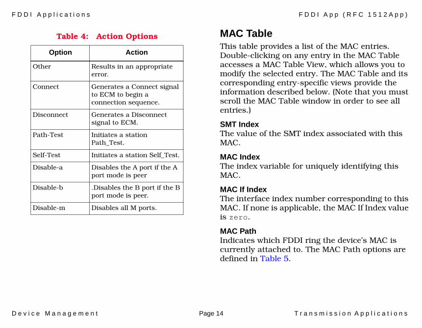
MAC TableThis table provides a list of the MAC entries. Double-clicking on any entry in the MAC Table accesses a MAC Table View, which allows you to modify the selected entry. The MAC Table and its corresponding entry-specific views provide the information described below. (Note that you must scroll the MAC Table window in order to see all entries.)
SMT IndexThe value of the SMT index associated with this MAC.
MAC IndexThe index variable for uniquely identifying this MAC.
MAC If IndexThe interface index number corresponding to this MAC. If none is applicable, the MAC If Index value is zero.
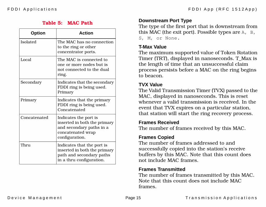
MAC PathIndicates which FDDI ring the device’s MAC is currently attached to. The MAC Path options are defined in Table 5.
Table 4: Action Options
Option Action
Other Results in an appropriate error.
Connect Generates a Connect signal to ECM to begin a connection sequence.
Disconnect Generates a Disconnect signal to ECM.
Path-Test Initiates a station Path_Test.
Self-Test Initiates a station Self_Test.
Disable-a Disables the A port if the A port mode is peer
Disable-b .Disables the B port if the B port mode is peer.
Disable-m Disables all M ports.
F D D I A p p l i c a t i o n s F D D I A p p ( R F C 1 5 1 2 A p p )
D e v i c e M a n a g e m e n t Page 15 T r a n s m i s s i o n A p p l i c a t i o n s
Downstream Port TypeThe type of the first port that is downstream from this MAC (the exit port). Possible types are A, B, S, M, or None.
T-Max ValueThe maximum supported value of Token Rotation Timer (TRT), displayed in nanoseconds. T_Max is the length of time that an unsuccessful claim process persists before a MAC on the ring begins to beacon.
TVX ValueThe Valid Transmission Timer (TVX) passed to the MAC, displayed in nanoseconds. This is reset whenever a valid transmission is received. In the event that TVX expires on a particular station, that station will start the ring recovery process.
Frames ReceivedThe number of frames received by this MAC.
Frames CopiedThe number of frames addressed to and successfully copied into the station’s receive buffers by this MAC. Note that this count does not include MAC frames.
Frames TransmittedThe number of frames transmitted by this MAC. Note that this count does not include MAC frames.
Table 5: MAC Path
Option Action
Isolated The MAC has no connection to the ring or other concentrator ports.
Local The MAC is connected to one or more nodes but is not connected to the dual ring.
Secondary Indicates that the secondary FDDI ring is being used.Primary
Primary Indicates that the primary FDDI ring is being used.Concatenated
Concatenated Indicates the port is inserted in both the primary and secondary paths in a concatenated wrap configuration.
Thru Indicates that the port is inserted in both the primary path and secondary paths in a thru configuration.

F D D I A p p l i c a t i o n s F D D I A p p ( R F C 1 5 1 2 A p p )
D e v i c e M a n a g e m e n t Page 16 T r a n s m i s s i o n A p p l i c a t i o n s
ErrorsThe number of frames that were detected in error by this MAC that had not been detected in error by another MAC.
Format ErrorsThe number of instances in which this MAC detected a format error during frame reception such that the frame was stripped.
ThresholdA threshold which, when exceeded, causes the generation of a MAC Condition report. Stations not supporting variable thresholds will have a value of 0. This field can be modified.
RMT StateThe current state of the Ring Management (RMT) State Machine. The possible states are defined in Table 6.
Table 6: RMT States
State Definition
Ring-Op The ring is functioning normally
Isolated The device is not attached to the main ring through its A and B ports.
Non-Op The device is attempting to enter the ring.
Detect The claim (beacon) process of the FDDI ring protocol has exceeded one second; there may be a problem on the ring. In this state, the ring is still alive, but no data is being transmitted.
Non-Op-Dup
The ring is not operational; a duplicate MAC address may have been discovered during the ring initialization process. This state is unlikely to occur unless you are using locally administered addresses, as factory-set MAC addresses are guaranteed to be unique.
Ring-Op-Dup
The ring is operational; however, a duplicate address has been detected. Like Non-Op-Dup, this state is unlikely to occur unless you are using locally-administered addresses.
Directed The beacon process did not complete within 7 seconds. The device is sending directed beacons to notify the other stations that a serious problem exists on the ring, and a Trace state is soon to follow.
Trace A problem exists on the ring that could not be corrected during the beaconing process, and a Trace has been initiated. During a Trace, the device sends a signal that forces its nearest upstream neighbor to remove from the ring and conduct a self-test.
Table 6: RMT States (Continued)
State Definition

F D D I A p p l i c a t i o n s F D D I A p p ( R F C 1 5 1 2 A p p )
D e v i c e M a n a g e m e n t Page 17 T r a n s m i s s i o n A p p l i c a t i o n s
Dup AddressIndicates the current status of the duplicate address detection function. Possible states are defined in Table 7.
Hardware PresentThis variable indicates the presence of underlying hardware support for this MAC object. Possible entries are True or False.
Table 7: Current Status
Status Definition
None Indicates the duplicate address test has not been completed.
Pass Indicates the duplicate address test has completed and has not detected a duplicate address.
Fail Indicates the duplicate address test has completed and has detected a duplicate address. This complements the duplicate address detection function of RMT, which operates when the logical ring is not operational.

D e v i c e M a n a g e m e n t Page 18 T r a n s m i s s i o n A p p l i c a t i o n s
Point-To-Point Application
The Point-to-Point Protocol (PPP) Application provides a method for transmitting datagrams over serial point-to-point links. This section provides access information for the PPP Application Views and describes the view fields available for the PPP application.
Four PPP application-specific views exist within SPECTRUM. These views can be obtained from the PPP_LCPApp1471 App Icon Subviews menu:
• PPP LCP Application Configuration View (Page 18)
• PPP Link Status Configuration View - Local to Remote Configuration Table (Page 19)
• PPP Link Status Configuration Table View - Remote to Local Configuration View (Page 20)
• PPP Link Status Table View (Page 21)
PPP LCP Application Configuration ViewAccess: From the Icon Subviews menu for the PPP_LCPApp1471 Application icon, select Configuration.
Double-clicking an entry in the PPP Link Configuration Table (within the PPP LCP
Application Configuration View) displays the PPP LCP Configuration View (Page 19).
Interface Index A unique value assigned to identify the interface on that WAN connection. Not available in the ETWMIM.
Initial MRUThe initial Maximum Receive Unit (MRU) that the local PPP device advertises to the remote device.
Receive ACC MapThe Asynchronous-Control-Character-Map (ACC) a local PPP device requires for use on its receive side.
Transmit ACC MapThe Asynchronous-Control-Character-Map (ACC) a local PPP device requires on its transmit side.

P o i n t - T o - P o i n t A p p l i c a t i o n P P P L i n k S t a t u s C o n f i g u r a t i o n V i e w - L o c a l t o R e m o t e
D e v i c e M a n a g e m e n t Page 19 T r a n s m i s s i o n A p p l i c a t i o n s
Magic NumberIndicates whether the local PPP Entity will attempt to perform Magic Number Negotiation with the remote node. Possible entries are true (attempts negotiation), and false (negotiation is not attempted).
FCS SizeIndicates the size of the Frame Check Sequence (FCS) in bits. The local device attempts to negotiate usage with the remote device.
PPP LCP Configuration ViewThis View identifies the LCP (Link Control Protocol) configuration parameters for this PPP Link. These variables represent the initial configuration of the PPP Link. The actual values of the parameters change when the link is brought up via the LCP options negotiation mechanism.
PPP Link Status Configuration View - Local to Remote Configuration Table Access: From the Icon Subviews menu for the PPP_LCPApp1471 Application icon, select Local to Remote Configuration.
Physical Index The unique value assigned to identify the low-level interface over which this PPP Link is operating. This interface would usually be an HDLC or RS-232 type of interface. If there is no other element that can be identified, then the value of this field is 0. For example, if PPP operates over a serial port there will be two entries in the Table. The PPP could be running over ‘interface’ number 123 and the serial port could be running over ‘interface’ number 987. Therefore, ifSpecific.123 would contain the object ID PPP. ETWMIM - refers to this field as PPP Link.
IF Index A unique value for each PPP Link. The value must remain constant from one re-initialization of the system to the next. ETWMIM refers to this field as PPP Link.
P o i n t - T o - P o i n t A p p l i c a t i o n P P P L i n k S t a t u s C o n f i g u r a t i o n T a b l e V i e w - R e m o t e t o L o c a l
D e v i c e M a n a g e m e n t Page 20 T r a n s m i s s i o n A p p l i c a t i o n s
Local MRUThe initial Maximum Receive Unit (MRU) that the remote PPP entity will advertise to the local entity. If this value is set to 0, no MRU is advertised and the default MRU is assumed. Changes are enabled upon the next link restart.
ACC MapThe Asynchronous Control Character (ACC) Map that the remote PPP entity requires for use on the receive side of the link. Changes are enabled upon the next link restart.
ACCThe Asynchronous Control Character (ACC) Map that the remote PPP entity requires for use on the transmit side of the link. Changes are enabled upon the next link restart.
Protocol CompressionIndicates if the remote PPP entity will use Address and Control Compression when transmitting packets to the remote PPP entity.
FCS SizeThis field displays size, in bits, of FCS (Frame Check Sequence) the remote node will generate when sending packets to the local entity.
The PPP protocol indicates whether the remote PPP entity will use Protocol Compression when transmitting packets to the local PPP entity. The
value of this field is meaningful only when the link reaches the open state. Figure shows the PPP Link Status Configuration View, with remote to local configuration information.
PPP Link Status Configuration Table View - Remote to Local Configuration ViewAccess: From the Icon Subviews menu for the PPP_LCPApp1471 Application icon, select Remote to Local Configuration.
Physical Index The unique value assigned to identify the low-level interface over which this PPP Link is operating. This interface would usually be an HDLC or Rs-232 type of interface. If there is no other element that can be identified, then the value of this field is 0. For example, if PPP operates over a serial port there will be two entries in the Table. The PPP could be running over ‘interface’ number 123 and the serial port could be running over ‘interface’ number 987. Therefore, ifSpecific.123 would contain the object ID PPP. ETWMIM refers to this field as PPP Link.

P o i n t - T o - P o i n t A p p l i c a t i o n P P P L i n k S t a t u s T a b l e V i e w
D e v i c e M a n a g e m e n t Page 21 T r a n s m i s s i o n A p p l i c a t i o n s
IF IndexA unique value for each PPP Link. The value remains constant from one re-initialization of the network management system to the next. ETWMIM refers to this field as PPP Link.
Remote MRUThe initial Maximum Receive Unit (MRU) that the local PPP entity will advertise to the remote entity. If this value is set to 0, no MRU is advertised and the default MRU is assumed. Changes are enabled upon the next link restart.
ACC MapThe Asynchronous Control Character (ACC) Map that the local PPP entity requires for use on the receive side of the link. Changes are enabled upon the next link restart.
ACCThe Asynchronous Control Character (ACC) Map that the local PPP entity requires for use on the transmit side of the link. Changes are enabled upon the next link restart.
Protocol CompressionThis field indicates whether the local PPP entity will use Address and Control Compression when transmitting packets to the remote PPP entity.
FCS SizeThis field displays the size, in bits, of FCS (Frame Check Sequence) that the local node will generate when sending packets to the remote entity.
Double-clicking a table entry brings up the PPP Link Status Performance View, which shows a single pie chart. Refer to the SPECTRUM Views documentation for more information on pie chart statistics.
PPP Link Status Table ViewAccess: From the Icon Subviews menu for the PPP_LCPApp1471 Application icon, select Link Status Table.
IF IndexThe unique identifier as it relates to the port (interface); n/a for the ETWMIM.
Physical IndexThe unique value assigned to identify the low-level interface over which this PPP Link is operating. This interface would usually be an HDLC or Rs-232 type of interface. If there is no other element that can be identified, then the value of this field is 0. For example, if PPP operates over a serial port there will be two entries in the table. The PPP could be running over ‘interface’ number 123 and the serial port
P o i n t - T o - P o i n t A p p l i c a t i o n P P P L i n k S t a t u s T a b l e V i e w
D e v i c e M a n a g e m e n t Page 22 T r a n s m i s s i o n A p p l i c a t i o n s
could be running over ‘interface’ number 987. Therefore, ifSpecific.123 would contain the object ID PPP.
Bad AddressesThis value indicates the number of addresses that do not follow a legal format.
Bad ControlsThis value indicates the number of illegitimate controls used.
Packet Too Longs This value indicates the number of oversized packets, or giants. ETWMIM refers to this field as Too Longs.
Bad FCSsThis value indicates the number of illegal Frame Check Sequence (FCS) that occurred during transmission. This often refers to extra characters added to a frame for error control purposes.
TotalIndicates the total number of errors received regarding link status with the device; n/a for ETWMIM.
D e v i c e M a n a g e m e n t Page 23 T r a n s m i s s i o n A p p l i c a t i o n s
DS1 Application
DS1 is a high-speed baseband transmission link. This section provides access information to the DS1 Application Views.
DS1App1406 ApplicationThis application (DSIAPP1406) has three menu options that provide access to the following views.
• DS1 Configuration Table (Page 23)• DS1 Fractional Table (Page 28)• DS1App1406 Current Table View (Page 28)
DS1 Configuration TableAccess: From the Icon Subviews menu for the DS1App1406 Application icon, select DS1 Configuration Table.
This table contains the configuration information for the DS1 Application.
DS1 IndexThe identifier of a DS1 Interface on a managed device.
If IndexThe value for this field is equal to the value of Interface Index from the Interfaces table of MIB II (RFC1213).
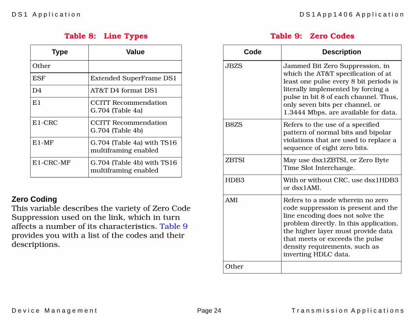
Line TypeThis variable indicates the variety of DS1 Line implementing this circuit. The type of circuit affects the number of bits per second that the circuit can reasonably carry, as well as the interpretation of the usage and error statistics. Table 8 provides you with a list of the line types and their values.
D S 1 A p p l i c a t i o n D S 1 A p p 1 4 0 6 A p p l i c a t i o n
D e v i c e M a n a g e m e n t Page 24 T r a n s m i s s i o n A p p l i c a t i o n s
Zero CodingThis variable describes the variety of Zero Code Suppression used on the link, which in turn affects a number of its characteristics. Table 9 provides you with a list of the codes and their descriptions.
Table 8: Line Types
Type Value
Other
ESF Extended SuperFrame DS1
D4 AT&T D4 format DS1
E1 CCITT Recommendation G.704 (Table 4a)
E1-CRC CCITT Recommendation G.704 (Table 4b)
E1-MF G.704 (Table 4a) with TS16 multiframing enabled
E1-CRC-MF G.704 (Table 4b) with TS16 multiframing enabled
Table 9: Zero Codes
Code Description
JBZS Jammed Bit Zero Suppression, in which the AT&T specification of at least one pulse every 8 bit periods is literally implemented by forcing a pulse in bit 8 of each channel. Thus, only seven bits per channel, or 1.3444 Mbps, are available for data.
B8ZS Refers to the use of a specified pattern of normal bits and bipolar violations that are used to replace a sequence of eight zero bits.
ZBTSI May use dsx1ZBTSI, or Zero Byte Time Slot Interchange.
HDB3 With or without CRC, use dsx1HDB3 or dsx1AMI.
AMI Refers to a mode wherein no zero code suppression is present and the line encoding does not solve the problem directly. In this application, the higher layer must provide data that meets or exceeds the pulse density requirements, such as inverting HDLC data.
Other

D S 1 A p p l i c a t i o n D S 1 A p p 1 4 0 6 A p p l i c a t i o n
D e v i c e M a n a g e m e n t Page 25 T r a n s m i s s i o n A p p l i c a t i o n s
Send CodeThis variable indicates what type of code is being sent across the DS1 interface by the device. Table 10 describes the send codes and their meanings.
Vendor IDThis variable contains the transmission vendor’s circuit identifier, for the purpose of facilitating troubleshooting.
Loopback ConfigThis variable represents the loopback configuration of the DS1 interface. Agents supporting read/write access should return badValue in response to a requested loopback state that the interface does not support. Table 11 describes the loopback configurations and their meanings.
Table 10: Send Codes
Code Description
NormalData Sending looped or normal data.
LineCode Sending a request for a line loopback.
PayloadCode Sending a request for a payload loopback.
ResetCode Sending a loopback termination request.
QRS Sending a Quasi-Random Signal (QRS) test pattern.
511Pattern Sending a 511 bit fixed test pattern.
3in24Pattern Sending a fixed test pattern of 3 bits set in 24.
OtherTestPattern Sending a test pattern other than those described by this field.

D S 1 A p p l i c a t i o n D S 1 A p p 1 4 0 6 A p p l i c a t i o n
D e v i c e M a n a g e m e n t Page 26 T r a n s m i s s i o n A p p l i c a t i o n s
Line StatusThis variable indicates the Line Status of the interface. It contains loopback, failure, received alarm and transmitted alarm information. The Line Status is a bit map represented as a sum; therefore, it can represent multiple failures (alarms) and a Loopback State simultaneously. The various bit positions are shown in Table 12.
Table 11: Loopback Configurations
Value Description
NoLoop Not in the loopback state. A device that is not capable of performing a loopback on the interface shall always return this as its value.
PayloadLoop The received signal at this interface is looped through the device. Typically the received signal is looped back for retransmission after it has passed through the device’s framing function.
LineLoop The received signal at this interface does not go through the device (minimum penetration) but is looped back out.
OtherLoop Loopbacks that are not defined here.
Table 12: Line Statuses
Bit Status Description
1 NoAlarm No Alarm Present
2 RcvFarEndLOF Far end LOF (a.k.a., Yellow Alarm
4 XmtFarEndLOF Near end sending LOF Indication
8 RcvAIS Far end sending AIS
16 XmtAIS Near end sending AIS
32 LossOfFrame Near end LOF (a.k.a., Red Alarm)
64 LossOfSignal Near end Loss Of Signal
128 LoopbackState Near end is looped
256 T16AIS E1 TS16 AIS
512 RcvFarEndLOMF Far End Sending TS16 LOMF
1024 XmtFarEndLOMF Near End Sending TS16 LOMF
2048 RcvTestCode Near End detects a test code
4096 OtherFailure Any line status not defined.

D S 1 A p p l i c a t i o n D S 1 A p p 1 4 0 6 A p p l i c a t i o n
D e v i c e M a n a g e m e n t Page 27 T r a n s m i s s i o n A p p l i c a t i o n s
Signal ModeThe following table (Table 13) describes the signal modes that are available.
Transmit ClockThe following table (Table 14) describes the sources for the Transmit Clock.
Facilities Data LinkThis bitmap describes the use of the facilities data link, and is the sum of the capabilities as shown in Table 15.
Table 13: Signal Modes
Mode Description
none Indicates that no bits are reserved for signaling on this channel.
robbedBit Indicates that T1 Robbed Bit Signaling is in use.
bitOriented Indicates that E1 Channel Associated Signaling is in use.
messageOriented Indicates that Common Channel Signaling is in use either on channel 16 of an E1 link or channel 24 of a T1.
Table 14: Transmit Clock Sources
Code Description
Loop Indicates that the recovered receive clock is used as the transmit clock.
Local Indicates that a local clock source is used.
Through Indicates that recovered receive clock from another interface is used as the transmit clock.

D S 1 A p p l i c a t i o n D S 1 A p p 1 4 0 6 A p p l i c a t i o n
D e v i c e M a n a g e m e n t Page 28 T r a n s m i s s i o n A p p l i c a t i o n s
DS1 Fractional TableAccess: From the Icon Subviews menu for the DS1App1406 Application icon, select DS1Fractional Table.
This table contains the fractional information for the DS1App1406 Application.
DS1 IndexThe index value uniquely identifying the DS1 interface to which this entry is applicable.
Channel NumberThe channel number for this entry.
If IndexAn index value that uniquely identifies an interface. If no interface is currently using a
channel, the value should be zero. If a single interface occupies more than one time slot, that ifIndex value will be found in multiple time slots.
DS1App1406 Current Table ViewAccess: From the Icon Subviews menu for the DS1App1406 Application icon, select DS1 Current Table.
The DS1 current table contains various statistics being collected for the current 15 minute interval.
IndexThe index value which uniquely identifies the DS1 interface to which this entry is applicable.
ESsThe number of Errored Seconds, encountered by a DS1 interface in the current 15 minute interval.
SESsThe number of Severely Errored Seconds encoun- tered by a DS1 interface in the current 15 minute interval.
SEFsThe number of Severely Errored Framing Seconds encountered by a DS1 interface in the current 15 minute interval.
Table 15: Facilities Data Link Codes
Code Description
Other Indicates that a protocol other than the one following is used.
Ansi-T1-403 Refers to the FDL exchange recommended by ANSI.
Att-54016 Refers to ESF FDL exchanges.
None Indicates that the device does not use the FDL.

D S 1 A p p l i c a t i o n D S 1 A p p 1 4 0 6 A p p l i c a t i o n
D e v i c e M a n a g e m e n t Page 29 T r a n s m i s s i o n A p p l i c a t i o n s
UASsThe number of Unavailable Seconds encountered by a DS1 interface in the current 15 minute interval.
CSSsThe number of Controlled Slip Seconds encoun- tered by a DS1 interface in the current 15 minute interval.
PCVsThe number of Path Coding Violations encountered by a DS1 interface in the current 15 minute interval.
LESsThe number of Line Errored Seconds encountered by a DS1 interface in the current 15 minute interval.
BESsThe number of Bursty Errored Seconds (BESs) encountered by a DS1 interface in the current 15 minute interval.
DMsThe number of Degraded Minutes (DMs) encoun- tered by a DS1 interface in the current 15 minute interval.
LCVsThe number of Line Code Violations (LCVs) en- countered by a DS1 interface in the current 15 minute interval.

D e v i c e M a n a g e m e n t Page 30 T r a n s m i s s i o n A p p l i c a t i o n s
DS3 Application (DS3App1407)
DS3 is a high-speed transmission application. This section describes the fields contained in the DS3 Application views.
This application provides access to the following device-specific tables:
• DS3/E3 Configuration Table• DS3/E3 Current Table (Page 32)• DS3/E3 Interval Table (Page 33)• DS3/E3 Total Table (Page 34)
DS3/E3 Configuration TableAccess: From the Icon Subviews menu for the Ds3App1407 Application icon, select DS3/E3 Configuration.
This table contains the following fields.
Line IndexIdentifies a DS3/E3 interface on a managed device. If there is an ifEntry directly associated with this and only this interface, it will have the same value as the If Index field.
If IndexA value equal to the value of ifIndex from the Interfaces table of MIB II (RFC 1213).
Time ElapsedThe number of seconds that have elapsed since the beginning of the near end current error measurement period.
Valid IntervalsThe number of near end intervals for which valid data was collected. The value will be 96 unless the interface was brought on line within the last 24 hours, in which case the value will be the number of complete 15-minute near end intervals since the interface was brought on line.
Line TypeThe type of DS3 C-bit or E3 application used on this interface. The type of interface affects the interpretation of the usage and error statistics. The rate of DS3 is 44.736 Mbps and E3 is 34.368 Mbps. The values conform to the specifications listed below. The dsx3ClearChannel value

D S 3 A p p l i c a t i o n ( D S 3 A p p 1 4 0 7 ) D S 3 / E 3 C o n f i g u r a t i o n T a b l e
D e v i c e M a n a g e m e n t Page 31 T r a n s m i s s i o n A p p l i c a t i o n s
means that the C-bits are not used except for sending/receiving AIS.
Table 16: Line Type Specifications
Line CodingThe type of Zero Code Suppression used on this interface. The values dsx3B3ZS and e3HDB3 refer to the use of specified patterns of normal bits and bipolar violations, which are used to replace sequences of zero bits of a specified length. The other possible value is dsx3Other.
Loopback ConfigThe loopback configuration of the DS3/E3 interface. Possible values are shown in Table 17.
-
Line StatusThe line status of the interface, which includes loopback state and failure state information. The value is a bit map represented as a sum; therefore, it can represent multiple failures and a
Value Specification
dsx3M23 ANSI T1.107-1988
dsx3SYNTRAN ANSI T1.107-1988
dsx3CbitParity ANSI T1.107a-1989
dsx3ClearChannel ANSI T1.102-1987
e3Framed CCITT G.751
e3Plcp ETSI T/NA(91)18.
Table 17: Loopback Configuration Values
Value Definition
dsx3NoLoop not in the loopback state. A device that is not capable of performing a loopback on the interface always returns this as it’s value.
dsx3PayloadLoop the received signal at this interface is looped through the device. Typically, the received signal is looped back for retransmission after it has passed through the device’s framing function.
dsx3LineLoop the received signal at this interface does not go through the device (minimum penetration) but is looped back out.
dsx3OtherLoop loopbacks that are not defined here.
D S 3 A p p l i c a t i o n ( D S 3 A p p 1 4 0 7 ) D S 3 / E 3 C u r r e n t T a b l e
D e v i c e M a n a g e m e n t Page 32 T r a n s m i s s i o n A p p l i c a t i o n s
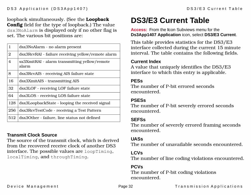
loopback simultaneously. (See the Loopback Config field for the type of loopback.) The value dsx3NoAlarm is displayed only if no other flag is set. The various bit positions are:
Transmit Clock SourceThe source of the transmit clock, which is derived from the recovered receive clock of another DS3 interface. The possible values are loopTiming, localTiming, and throughTiming.
DS3/E3 Current TableAccess: From the Icon Subviews menu for the Ds3App1407 Application icon, select DS3/E3 Current.
This table provides statistics for the DS3/E3 interface collected during the current 15 minute interval. The table contains the following fields.
Current IndexA value that uniquely identifies the DS3/E3 interface to which this entry is applicable.
PESsThe number of P-bit errored seconds encountered.
PSESsThe number of P-bit severely errored seconds encountered.
SEFSsThe number of severely errored framing seconds encountered.
UASsThe number of unavailable seconds encountered.
LCVsThe number of line coding violations encountered.
PCVsThe number of P-bit coding violations encountered.
1 dsx3NoAlarm - no alarm present
2 dsx3RcvRAI - failure receiving yellow/remote alarm
4 sx3XmitRAI - alarm transmitting yellow/remote alarm
8 dsx3RcvAIS - receiving AIS failure state
16 dsx3XmitAIS - transmitting AIS
32 dsx3LOF - receiving LOF failure state
64 dsx3LOS - receiving LOS failure state
128 dsx3LoopbackState - looping the received signal
256 dsx3RcvTestCode - receiving a Test Pattern
512 dsx3Other - failure, line status not defined
D S 3 A p p l i c a t i o n ( D S 3 A p p 1 4 0 7 ) D S 3 / E 3 I n t e r v a l T a b l e
D e v i c e M a n a g e m e n t Page 33 T r a n s m i s s i o n A p p l i c a t i o n s
LESsThe number of line errored seconds encountered.
CCVsThe number of C-bit coding violations encountered.
CESsThe number of C-bit errored seconds encountered.
CSESsThe number of C-bit severely errored seconds encountered.
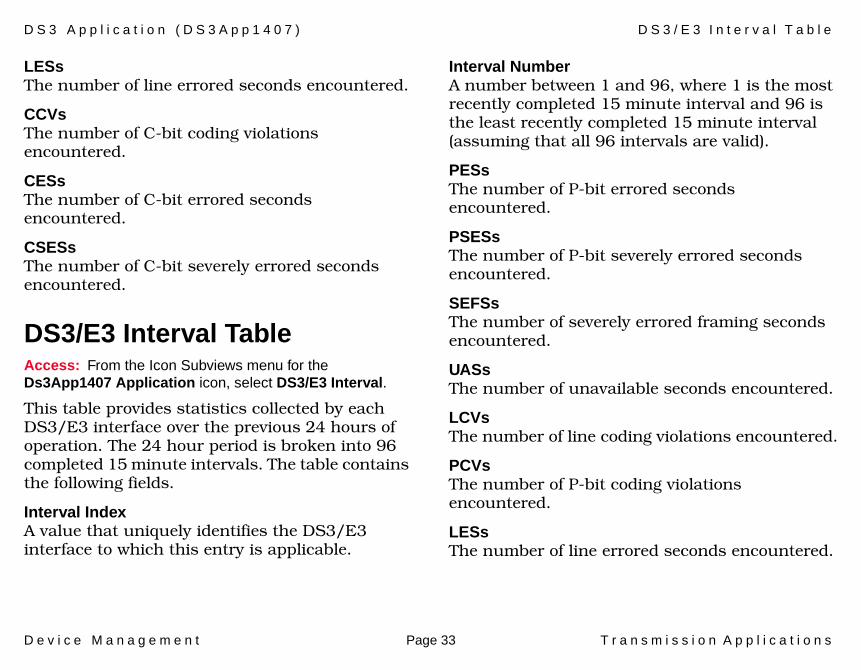
DS3/E3 Interval TableAccess: From the Icon Subviews menu for the Ds3App1407 Application icon, select DS3/E3 Interval.
This table provides statistics collected by each DS3/E3 interface over the previous 24 hours of operation. The 24 hour period is broken into 96 completed 15 minute intervals. The table contains the following fields.
Interval IndexA value that uniquely identifies the DS3/E3 interface to which this entry is applicable.
Interval NumberA number between 1 and 96, where 1 is the most recently completed 15 minute interval and 96 is the least recently completed 15 minute interval (assuming that all 96 intervals are valid).
PESsThe number of P-bit errored seconds encountered.
PSESsThe number of P-bit severely errored seconds encountered.
SEFSsThe number of severely errored framing seconds encountered.
UASsThe number of unavailable seconds encountered.
LCVsThe number of line coding violations encountered.
PCVsThe number of P-bit coding violations encountered.
LESsThe number of line errored seconds encountered.

D S 3 A p p l i c a t i o n ( D S 3 A p p 1 4 0 7 ) D S 3 / E 3 T o t a l T a b l e
D e v i c e M a n a g e m e n t Page 34 T r a n s m i s s i o n A p p l i c a t i o n s
CCVsThe number of C-bit coding violations encountered.
CESsThe number of C-bit errored seconds encountered.
CSESsThe number of C-bit severely errored seconds encountered.
DS3/E3 Total TableAccess: From the Icon Subviews menu for the Ds3App1407 Application icon, select DS3/E3 Total.
This table provides the cumulative statistics for the 24 hour period preceding the current interval. The table contains the following fields.
Total IndexA value that uniquely identifies the DS3/E3 interface to which this entry is applicable.
PESsThe number of P-bit errored seconds encountered.
PSESsThe number of P-bit severely errored seconds encountered.
SEFSsThe number of severely errored framing seconds encountered.
UASsThe number of unavailable seconds encountered.
LCVsThe number of line coding violations encountered.
PCVsThe number of P-bit coding violations encountered.
LESsThe number of line errored seconds encountered.
CCVsThe number of C-bit coding violations encountered.
CESsThe number of C-bit errored seconds encountered.
CSESsThe number of C-bit severely errored seconds encountered.
D e v i c e M a n a g e m e n t Page 35 T r a n s m i s s i o n A p p l i c a t i o n s
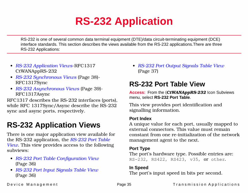
RS-232 Application
RS-232 is one of several common data terminal equipment (DTE)/data circuit-terminating equipment (DCE) interface standards. This section describes the views available from the RS-232 applications.There are three RS-232 Applications:
• RS-232 Application Views-RFC1317 CtWANAppRS-232
• RS-232 Synchronous Views (Page 38)-RFC1317Sync
• RS-232 Asynchronous Views (Page 39)-RFC1317Async
RFC1317 describes the RS-232 interfaces (ports), while RFC 1317Sync/Async describe the RS-232 sync and async ports, respectively.
RS-232 Application ViewsThere is one major application view available for the RS-232 application, the RS-232 Port Table View. This view provides access to the following subviews:
• RS-232 Port Table Configuration View (Page 36)
• RS-232 Port Input Signals Table View (Page 36)
• RS-232 Port Output Signals Table View (Page 37)
RS-232 Port Table ViewAccess: From the (CtWANAppRS-232 Icon Subviews menu, select RS-232 Port Table.
This view provides port identification and signalling information.
Port IndexA unique value for each port, usually mapped to external connectors. This value must remain constant from one re-initialization of the network management agent to the next.
Port TypeThe port’s hardware type. Possible entries are: RS-232, RS422, RS423, v35, or other.
In SpeedThe port’s input speed in bits per second.

R S - 2 3 2 A p p l i c a t i o n R S - 2 3 2 A p p l i c a t i o n V i e w s
D e v i c e M a n a g e m e n t Page 36 T r a n s m i s s i o n A p p l i c a t i o n s
Out SpeedThe port’s output speed in bits per second.
In SignalsThe number of input signals for this port in the input signal table.
Out SignalsThe number of output signals for this port in the output signal table.
CTSWhen enabled, this field indicates that a CTS (Clear to Send) signal is generated. (ETWMIM only)
DSR When enabled, this field indicates that a DST (Data Set Ready) signal is generated. (ETWMIM only)
RS-232 Port Table Configuration ViewAccess: Double-click on an entry in the RS-232 Port Table.
The Port Table Configuration View allows you to modify or reconfigure a selected port within the Port Table View.
Accesses the RS-232 Port Input Signals Table View, which provides the number of input signals for the port in the input signal table. The table contains entries only for those signals the software can detect.
Accesses the RS-232 Port Output Signals Table View, which provides the number of output signals for the port in the output signal table. The table contains entries only for those signals the software can detect.
RS-232 Port Input Signals Table ViewAccess: Click the Input Signals Detail button in the RS-232 Port Table Configuration View.
This view provides the number of input signals for the port. The table contains entries only for those signals the software can detect.
Port IDThe unique numeric identifier for the port corresponding to the table entry.
Signal NameIndicates the hardware signal. Table 18 lists possible entries.
Input Signals Detail
Output Signals Detail

R S - 2 3 2 A p p l i c a t i o n R S - 2 3 2 A p p l i c a t i o n V i e w s
D e v i c e M a n a g e m e n t Page 37 T r a n s m i s s i o n A p p l i c a t i o n s
StateThe current signal state. Possible entries are: None, On, & Off.
ChangesThe number of times that the signal has changed its signal state.
RS-232 Port Output Signals Table ViewAccess: Click the Output Signals Detail button in RS-232 Port Table Configuration View.
The view provides the number of output signals for the port. The table contains entries only for those signals the software can detect.
Port IDThe unique numeric identifier for the port corresponding to the table entry.
Signal NameIndicates the hardware signal. Table 19 shows possible entries.
Table 18: Signal Name
Entry Definition
rts Request to Send
cts Clear to Send
dsr Data Set Ready
dtr Data Terminal Ready
ri Ring Indicator
dcd Received Line Signal Detector
sq Signal Quality Detector
srs Data Signaling Rate Selector
srts Secondary Request to Send
scts Secondary Clear to Send
sdcd Secondary Received Line Signal Detector
Table 19: Signal Name
Entry Definition
rts Request to Send
cts Clear to Send
dsr Data Set Ready
dtr Data Terminal Ready
ri Ring Indicator
dcd Received Line Signal Detector

R S - 2 3 2 A p p l i c a t i o n R S - 2 3 2 S y n c h r o n o u s V i e w s
D e v i c e M a n a g e m e n t Page 38 T r a n s m i s s i o n A p p l i c a t i o n s
StateCurrent signal state. Possible entries are, None, On, & Off.
ChangesNumber of times the signal has changed its signal state.
CTSWhen enabled, this field indicates that a CTS (Clear To Send) signal is generated.
DSRWhen enabled, this field indicates that a DSR (Data Set Ready) signal is generated.
RS-232 Synchronous Views
There is one application-specific subview available for the RS-232 Sync application from the RFC1317Sync Icon Subviews menu, the RS-232 Synchronous Port Table View.
You can update, sort, or search the table for specific information. Double-clicking on a table entry opens the Synchronous Port Table Detail View (Page 39), which provides a color-coded pie chart of Error Breakdown for the selected port.
RS-232 Synchronous Port Table ViewAccess: From the Icon Subviews menu for the RFC1317Sync Application Icon, select Synchronous Port Table.
Port IDA unique value for each port mapped to external connectors. This value is similar to the RS-232 Port Index.
ClockSrcThe source of the port’s bit rate clock. Split means the transmit clock is internal and the receive clock is external.
sq Signal Quality Detector
srs Data Signaling Rate Selector
srts Secondary Request to Send
scts Secondary Clear to Send
sdcd Secondary Received Line Signal Detector
Table 19: Signal Name
Entry Definition
R S - 2 3 2 A p p l i c a t i o n R S - 2 3 2 A s y n c h r o n o u s V i e w s
D e v i c e M a n a g e m e n t Page 39 T r a n s m i s s i o n A p p l i c a t i o n s
Frame Check Errors The total number of frames with an invalid frame check sequence, input from the port since system re-initialization and while the port state was Up or Test.
Aborted Frames The number of frames aborted on the port due to receiving an abort sequence since system re-initialization and while the port state was Up or Test.
Interrupted Frames The total number of frames not received or transmitted on the port due to loss of modem signals since system re-initialization and while Port State was Up or Test.
Xmt. Underrun Errors Total number of frames that failed to be transmitted on the port, since system re-initialization and while the port state was Up or Test. Data was not available to the transmitter.
Rcv. Overrun Errors The total number of frames not received on the port, since system re-initialization and while the port state was Up or Test, because the receiver did not accept the data in time.
Synchronous Port Table Detail ViewAccess: Double-click on any entry in the Synchronous Port Table.
This view provides configuration information on a selected entry from the RS-232 Synchronous Port Table, and allows you to modify the configuration values. This view also provides a color-coded pie chart displaying error breakdown statistical information. A Clock Source button can be toggled between external, internal and split.
Error Breakdown Each statistic is presented as a total amount since the device was initialized and as a percentage of overall traffic. Three buttons at the bottom of the pie chart select the way in which the data is represented (Total, Delta, and Accum). Another button, Clear, works in conjunction with Accum.
RS-232 Asynchronous ViewsThere is one application-specific subview available for the RS-232 Asynchronous application, the RS-232 Asynchronous Port Table View.
Access the RS-232 Asynchronous Port Detail View (Page 41) subview by double-clicking table entries within the Asynchronous Port Table View.

R S - 2 3 2 A p p l i c a t i o n R S - 2 3 2 A s y n c h r o n o u s V i e w s
D e v i c e M a n a g e m e n t Page 40 T r a n s m i s s i o n A p p l i c a t i o n s
RS-232 Asynchronous Port Table ViewAccess: From the Icon Subviews menu for the RFC1317Async Application Icon, select Asynchronous Port Table.
You can update or sort the table for specific information. Double-clicking on a table entry opens the RS-232 Asynchronous Port Detail View, which allows you to modify the configuration of the selected entry
Port IDThe port index for this entry.
Data BitsThe number of bits allowed in a character.
Stop BitsThe number of stop bits. In the RS-232 Asynchronous Port Detail View, you may alter this value. Possible options are One, Two, One-and-Half, and Dynamic.
ParityThe character parity bit. In the RS-232 Asynchronous Port Detail View, you may alter this value. Possible options are None, Odd, Even, Mark, and Space.
AutoBaudThis field indicates whether the port can automatically sense input speed. You may Enable or Disable this feature in the RS-232 Asynchronous Port Detail View. When enabled, a port may set autobaud values differently than the configured values for speed, parity, and character size. As a result, the network management system may temporarily observe values different from the values previously set.
Parity ErrorsThe total number of characters with a parity error, input from the port since system re-initialization and while the port state was Up or Test. Possible choices are None, Odd, Even, Mark, and Space.
Framing ErrorsThe total number of characters with a framing error, input from the port since system re-initialization and while the port state was Up or Test.
Overrun ErrorsThe total number of characters with an overrun error, input from the port since system re-initialization and while the port state was Up or Test.
R S - 2 3 2 A p p l i c a t i o n R S - 2 3 2 A s y n c h r o n o u s V i e w s
D e v i c e M a n a g e m e n t Page 41 T r a n s m i s s i o n A p p l i c a t i o n s
RS-232 Asynchronous Port Detail ViewAccess: Double-click on any entry in the RS-232 Asynchronous Port Table.
This view provides configuration information on a selected entry from the RS-232 Asynchronous Port Table, and allows you to modify the configuration values. Three buttons can be toggled to change the Stop Bits, Parity and Autobaud settings. This view also provides a color-coded pie chart displaying error breakdown statistical information.
Error BreakdownThis pie chart displays a breakdown of errors. Each statistic is presented as a total amount since the device was initialized and as a percentage of overall traffic. Three buttons at the bottom of the pie chart select the way in which the data is represented (Total, Delta, and Accum). Another button, Clear, works in conjunction with the Accum button.
Parity ErrorsThe total number of characters with a parity error, input from the port since system re-initialization and while the port state was Up or Test. Possible choices are, None, Odd, Even, Mark, and Space.
Framing ErrorsThe total number of characters with a framing error, input from the port since system re-initialization and while the port state was Up or Test.
Overrun ErrorsThe total number of characters with an overrun error, input from the port since system re-initialization and while the port state was Up or Test.
D e v i c e M a n a g e m e n t Page 42 T r a n s m i s s i o n A p p l i c a t i o n s
WAN Application
Wide Area Network (WAN) data link technology is used to implement point-to-point connections between devices. This section describes the views accessed from the WAN application.
There is one application-specific view accessed from the CtWANApp Icon Subviews menu, the WAN Connection Table View.
The following subviews can be accessed from the WAN Connection Table View:
• WAN Connection Physical Ports View (Page 43)
• WAN Connection Interface Table View (Page 44)
WAN Connection Table ViewAccess: From the Icon Subviews menu for the CtWANApp Application Icon, select WAN Connections.
You can sort, search for, or update information within this table, which provides read-only Physical Port information. Double-click a table entry to open the WAN Connection Physical Ports View.
Total Connections Displays the number of connections made.
WAN ConnectionDisplays the index value uniquely identifying the connection.
Physical PortsDisplays the number of physical ports that exist on this WAN connection.
Primary PortDisplays the port number to which a WAN connection would default. When redundancy is disabled this physical port will always be used. When redundancy is enabled this physical port will be the primary port.
Active PortDisplays the physical port number which is active for the WAN connection.
W A N A p p l i c a t i o n W A N C o n n e c t i o n T a b l e V i e w
D e v i c e M a n a g e m e n t Page 43 T r a n s m i s s i o n A p p l i c a t i o n s
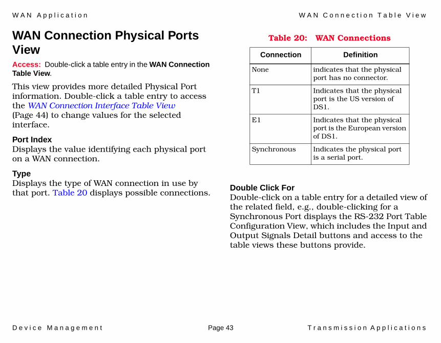
WAN Connection Physical Ports ViewAccess: Double-click a table entry in the WAN Connection Table View.
This view provides more detailed Physical Port information. Double-click a table entry to access the WAN Connection Interface Table View (Page 44) to change values for the selected interface.
Port IndexDisplays the value identifying each physical port on a WAN connection.
TypeDisplays the type of WAN connection in use by that port. Table 20 displays possible connections.
Double Click ForDouble-click on a table entry for a detailed view of the related field, e.g., double-clicking for a Synchronous Port displays the RS-232 Port Table Configuration View, which includes the Input and Output Signals Detail buttons and access to the table views these buttons provide.
Table 20: WAN Connections
Connection Definition
None indicates that the physical port has no connector.
T1 Indicates that the physical port is the US version of DS1.
E1 Indicates that the physical port is the European version of DS1.
Synchronous Indicates the physical port is a serial port.
W A N A p p l i c a t i o n W A N C o n n e c t i o n T a b l e V i e w
D e v i c e M a n a g e m e n t Page 44 T r a n s m i s s i o n A p p l i c a t i o n s
WAN Connection Interface Table View Access: In the WAN Connection Physical Ports View, double-click a Port Index or Type table entry.
This table provides read-only information about the physical port’s interfaces; you can print the table results. Double-clicking a table entry opens the WAN Interface View, which allows you to modify field values for the selected interface.
WAN ConnectionDisplays the index value identifying a connection to the WAN port.
Physical PortDisplays the index value uniquely identifying the WAN port.
Entry IndexDisplays the index value identifying the WAN port and associated connection.
If IndexDisplays the index value of this entry as an interface to a WAN in the MIB-II Interface Table.
ProtocolDisplays the protocol that should be run on this interface. This field is modifiable. Accepted values are product dependent. Refer to the Aprisma Systems BRIM-WT1 User’s Guide for more information.
CompressionThis read-write field indicates whether compression is On or Off.
MTUDesignates the MTU (Maximum Transmission Unit) that can be transmitted on the selected interface.
Line CodingThis describes the line coding. Possible values are, JBZS, B8ZS, HDB3, ZBTSI, AMI, and Other.
CRC LengthDisplays the length of the cyclical redundancy check (CRC). This value can be either 16-bits or 32-bits.
D e v i c e M a n a g e m e n t Page 45 T r a n s m i s s i o n A p p l i c a t i o n s
Frame Relay Application
Frame Relay is viewed as a multi-access media and not as a group of point-to-point connections.
Three application-specific subviews are available for the Frame Relay application.
• Virtual Circuit Table View• Circuit Error Table View (Page 46)• Interface Dlcmi Table View (Page 47)
These subviews are accessed from the RelayApp icon (in Icon Mode) or the Frame Relay text label (in List Mode) Icon Subviews menu.
To access information on a specific virtual circuit, double-click any table entry to open the Frame Relay Virtual Circuit Detail View.
Virtual Circuit Table ViewAccess: From the Icon Subviews menu for the RelayApp Application Icon, select VCircuit Table.
Line NumberLine number on which the associated frame relay interface resides.
LL IndexIdentifies the lower layer in cases where the lower layer may be something other than the physical layer. For example, if Frame Relay is running over an ATM virtual circuit, the LL Index identifies the ATM virtual circuit.
NumberCircuit number of this interface.
Dlci Frame relay “address” of the virtual circuit.
StateState of this virtual circuit. Possible states are Invalid, Active, Inactive, Xoff and Control.
MulticastIndicates whether this Dlcmi is used for multicast or single destination.

F r a m e R e l a y A p p l i c a t i o n C i r c u i t E r r o r T a b l e V i e w
D e v i c e M a n a g e m e n t Page 46 T r a n s m i s s i o n A p p l i c a t i o n s
TypeIndicates whether the virtual circuit was manually created (Static) or created by the Data Link Control Management interface (Dynamic).
ModeIndicates whether the virtual circuit’s mode is Group (the virtual circuit is one of many on a circuit), Hybrid (the virtual circuit is one of many on a circuit for protocol traffic, but is a separate circuit for bridging), or Direct (the virtual circuit is a separate circuit for all applications).
SubCctCircuit number to use for this VC when configured in hybrid (for bridging) or direct access (VC as a circuit) mode.
Congest StIndicates whether or not the virtual circuit is in a congested state. Possible states are Forwarding and Congested. If the state is Congested, no traffic will be sent on this virtual circuit.
Circuit Error Table ViewAccess: From the Icon Subviews menu for the RelayApp Application Icon, select Circuit Error Table.
This table provides statistical information on frame relay virtual circuits.
Circuit Frame relay circuit number. To see detailed error information on a specific virtual circuit, double-click any table entry for the circuit.
DropsNumber of frames dropped at the circuit level. A drop occurs because the particular protocol within the inbound frame is not registered for this circuit.
DiscardsNumber of frames discarded at the circuit level. A discard occurs because the outbound frame was too long or too short.
F r a m e R e l a y A p p l i c a t i o n I n t e r f a c e D l c m i T a b l e V i e w
D e v i c e M a n a g e m e n t Page 47 T r a n s m i s s i o n A p p l i c a t i o n s
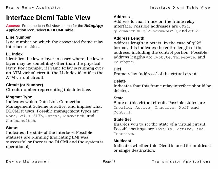
Interface Dlcmi Table ViewAccess: From the Icon Subviews menu for the RelayApp Application Icon, select IF DLCMI Table.
Line NumberLine number on which the associated frame relay interface resides.
LL IndexIdentifies the lower layer in cases where the lower layer may be something other than the physical layer. For example, if Frame Relay is running over an ATM virtual circuit, the LL Index identifies the ATM virtual circuit.
Circuit (or Number)Circuit number representing this interface.
Mngmnt TypeIndicates which Data Link Connection Management Scheme is active, and implies what DLCMI it uses. Possible management types are None, Lmi, T1617b, Annexa, Limswitch, and Annexaswitch.
StatusIndicates the state of the interface. Possible statuses are Running (indicating LMI was successful or there is no DLCMI and the system is operational).
AddressAddress format in use on the frame relay interface. Possible addresses are q921, q922march90, q922november90, and q922.
Address LengthAddress length in octets. In the case of q922 format, this indicates the entire length of the address, including the control portion. Possible address lengths are Twobyte, Threebyte, and Fourbyte.
DlciFrame relay “address” of the virtual circuit.
DeleteIndicates that this frame relay interface should be deleted.
StateState of this virtual circuit. Possible states are Invalid, Active, Inactive, Xoff and Control.
State SetEnables you to set the state of a virtual circuit. Possible settings are Invalid, Active, and Inactive.
MulticastIndicates whether this Dlcmi is used for multicast or single destination.
F r a m e R e l a y A p p l i c a t i o n I n t e r f a c e D l c m i T a b l e V i e w
D e v i c e M a n a g e m e n t Page 48 T r a n s m i s s i o n A p p l i c a t i o n s
TypeIndicates whether the virtual circuit was manually created (Static) or created by the Data Link Control Management interface (Dynamic).
ModeIndicates whether the virtual circuit’s mode is Group (the virtual circuit is one of many on a circuit), Hybrid (the virtual circuit is one of many on a circuit for protocol traffic, but is a separate circuit for bridging), or Direct (the virtual circuit is a separate circuit for all applications).
Congestion DisableIndicates whether the congestion algorithm should be used for this virtual circuit. If this is not set, the value is inherited from the Dlcmi record.

D e v i c e M a n a g e m e n t Page 49 T r a n s m i s s i o n A p p l i c a t i o n s
Token Ring Application
This section describes the views available for the Token Ring applications.
There are two Token Ring Applications:
• Token Ring Application• Token Ring IF Views (Page 51)
Token Ring ApplicationOne application-specific subview, the Token Ring Detail View (Page 49), is available for the Token Ring application. This view provides three color-coded pie charts displaying Token Ring statistical information. Each statistic is presented as a total amount since the device was initialized and as a percentage of overall traffic.
Token Ring Detail ViewAccess: From the Icon Subviews menu for the TokenRingApp Application Icon, select Detail.
Transmitted Beacon CountThe number of times this interface has transmitted a beacon frame.
Remove Ring Station CountThe number of times the interface has received a Remove Ring Station MAC frame request.
Soft Error CountThe number of times the interface has detected an immediately recoverable fatal error.
Isolating Soft Errors BreakdownThis pie chart displays a breakdown of the following statistics: Line, Burst, and A/C.
LineThe number of frames copied or repeated by a station.
BurstThe number of times a station detects the absence of transitions for five half-bit timers.
A/CThe number of times a station has incorrectly set the AC bit.

T o k e n R i n g A p p l i c a t i o n T o k e n R i n g A p p l i c a t i o n
D e v i c e M a n a g e m e n t Page 50 T r a n s m i s s i o n A p p l i c a t i o n s
Non-Isolating Soft Errors BreakdownThis pie chart displays a breakdown of the following statistics: Lost Frames, Congestions, Frame Copied, Recoveries, and Token.
Lost FramesThe number of times the TRR timer for a station expired while trying to transmit.
CongestionsThe number of times a station recognizes a frame addressed to it, but has no available buffer space.
Frame CopiedThe number of times a station recognizes a frame addressed (to the station). The detected FS field bit is set to the value one.
RecoveriesThe number of Claim Token MAC frames received or transmitted after the ring has received a Ring Purge MAC frame.
TokenThe number of times the station, which acts as the active monitor, recognizes an error. This condition requires a token be transmitted.
Hard Errors BreakdownThis pie chart displays the breakdown of the following statistics: Abort Trans, Internal, Signal Loss, Lobe Wire, and Frequency.
Abort TransThe number of times the station transmits an abort delimiter while transmitting.
InternalThe number of times the station recognizes an internal error.
Signal LossThe number of times the interface has detected the loss of signal condition from the ring.
Lobe WireThe number of times the interface has detected an open or short circuit in the lobe data path.
FrequencyThe number of times that the interface has detected that the frequency of the incoming signal differs from the expected frequency by more than the specified standard.
T o k e n R i n g A p p l i c a t i o n T o k e n R i n g I F V i e w s
D e v i c e M a n a g e m e n t Page 51 T r a n s m i s s i o n A p p l i c a t i o n s
Token Ring IF ViewsThree application-specific subviews are available for the Token Ring IF application:
• Token Ring IF Configuration View• Token Ring IF Performance View-This View
displays a breakdown of performance statistics. (For more information refer to Spectrum Views.)
• Token Ring IF Detail View-This View provides three color-coded pie charts displaying Token Ring statistical information. Each statistic is presented as a total amount since the device was initialized and as a percentage of overall traffic. (Refer to Spectrum Views.)
Token Ring IF Configuration ViewAccess: From the Icon Subviews menu for the TokenRingApp Application Icon, select Configuration.
CommandsProvides a button field that allows you to send the following commands to the device: None, Open, Reset and Close.
Ring SpeedProvides a button field that allows you to configure the device with the bandwidth of the
ring. You can choose from Unknown, 16 Megabits, 4 Megabits, and 1 Megabits.
Active Monitor ProcessAllows you to configure the device as an Active Monitor to participate in the active monitor bid on the Token Ring network, or to disable active monitor participation. Possible values are DoNotParticipate and Participate.
Functional Address BitmaskThe bit mask of all Token Ring functional addresses for which this interface will accept frames. You can enter the desired mask.
Ring StateIndicates whether this interface is entering or leaving the ring.
Ring Open-StatusThe success, or reason for failure, of the station’s most recent attempt to enter the ring.
Upstream NeighborThe MAC address of the upstream neighbor station.
Ring StatusThis area contains read-only indicator buttons displaying the current status of the network. The Ring Status indicator buttons are defined below.

T o k e n R i n g A p p l i c a t i o n T o k e n R i n g I F V i e w s
D e v i c e M a n a g e m e n t Page 52 T r a n s m i s s i o n A p p l i c a t i o n s
RingRecoveryThe ring purge command has not yet been issued to restart communications.
SingleStationThe device detected itself as the only station on the ring.
RemoveReceivedA station is removing itself from the ring.
Auto-RemovalErrorThe device has removed itself due to the beaconing auto-removal process.
LobeWireFaultThe device detected an error condition on the lobe wires.
TransmitBeaconThe device is transmitting a beacon frame.
SoftErrorThe device is sending an error report frame to the Ring Error Monitor.
HardErrorThe device detected the ring going into a beaconing state.
SignalLossThe device detected a signal loss condition on the ring.

D e v i c e M a n a g e m e n t Page 53 T r a n s m i s s i o n A p p l i c a t i o n s
Ethernet Application
This section describes the Ethernet Application Detail View, which contains ethernet network information.
The Ethernet Application provides one device-specific view, the Ethernet Application Detail View.
Ethernet Application Detail ViewAccess: From the icon subviews of the EthernetApp icon, select Detail.
The Ethernet Application Detail View provides three color-coded pie charts displaying ethernet statistical information. Each statistic is presented as a total amount since the device was initialized and as a percentage of overall traffic. The three pie charts are described below.
Transmit Success CountsSingle CollThe number of successfully transmitted frames for which transmission was inhibited by exactly one collision.
Multi CollThe number of successfully transmitted frames for which transmission was inhibited by more than one collision.
Defer TransThe number of frames for which the first transmission attempt was delayed because the medium was busy.
Frame ErrorsFCSThe number of frames received that are an integral number of octets in length but do not pass the FCS check.
Frame LengthThe number of frames received that exceed the maximum permitted frame size.
In-RangeThe number of frames received with a length field value that falls between the minimum unpadded

E t h e r n e t A p p l i c a t i o n E t h e r n e t A p p l i c a t i o n C o n f i g u r a t i o n V i e w
D e v i c e M a n a g e m e n t Page 54 T r a n s m i s s i o n A p p l i c a t i o n s
Logical Link Control (LLC) data size and the maximum allowed LLC data size and does not match the number of LLC octets received.
Out-RangeThe number of frames received for which the length field value exceeds the maximum allowed LLC data size.
MAC ReceiveThe number of frames that failed reception due to an internal MAC sublayer receive error.
AlignmentThe number of frames received that are not an integral number of octets in length and do not pass the FCS check.
Excess DeferThe number of frames for which transmission was deferred for an excessive period of time. (only for Ethernet IF App).
Transmit Fail ErrorsLate CollThe number of times that a collision was detected later than 51.2 microseconds into the transmission of a packet.
Excess CollThe number of frames for which transmission failed due to excessive collisions.
MAC TransmitThe number of frames that failed transmission due to an internal MAC sublayer transmit error.
Carrier SenseThe number of times that the carrier sense condition was lost or never asserted when attempting to transmit a frame.
Ethernet Application Configuration ViewAccess: From the icon subviews of the EthernetApp icon, select Configuration.
Use this view to set whether or not EthernetIfApps will be modeled. The default value is False. To create EthernetIfApps for physical interfaces, change “Create Interface Applications” to True then reconfigure the applications.

D e v i c e M a n a g e m e n t Page 55 T r a n s m i s s i o n A p p l i c a t i o n s
802dot11Application
This section describes the 802dot11 Application.
This application provides access to the following device-specific views and tables:
• Station Configuration Table View (Page 55)• Authentication Algorithms Table View
(Page 58)• Counters Table View (Page 58)• Group Address Table View (Page 60)• Operation Table View (Page 60)• Antenna List Table View (Page 62)• Physical Antenna Table View (Page 62)• Physical DSSS Entry Table View (Page 63)• Physical FHSS Table View (Page 63)• PhyIR Table View (Page 64)• Physical Operation Table View (Page 65)• Physical Transmission Power Table View
(Page 65)• Privacy Table View (Page 66)• Regulatory Domains Supported Table View
(Page 66)• Supported Data Rate Rx Table View (Page 67)
• Supported Data Rate Tx Table View (Page 67)• WEP Default Keys Table View (Page 67)• WEP Key Mappings Table View (Page 67)• Resource Information Table View (Page 68)
Station Configuration Table ViewAccess: From the Icon Subviews menu for the 802dot11App icon, select SMT Station Configuration.
This view provides Station Management (SMT) station configuration information in the following fields.
Note:Note:
In the table descriptions that follow, the fields notated as read-write are configurable. You can change a field value by double-clicking the value you want to change and then entering the new value in the ensuing detail view that displays.

8 0 2 d o t 1 1 A p p l i c a t i o n S t a t i o n C o n f i g u r a t i o n T a b l e V i e w
D e v i c e M a n a g e m e n t Page 56 T r a n s m i s s i o n A p p l i c a t i o n s
Medium Occupancy LimitA read-write field that sets the maximum time, in Time Units, that a point coordinator may control the usage of the wireless medium without relinquishing control for long enough to allow at least one instance of Distributed Coordination Function (DCF) access to the medium. The default value is 100 and the maximum is 1000.
CF-PollableA read-only field. A value of true indicates that the station is able to respond to a Contention Free (CF) Poll with a data frame within a Short Inter Frame Space (SIFS) time whereas false indicates it is not able to respond to a CF Poll with a data frame within a SIFS time.
CF-P PeriodA read-write field that specifies the number of DTIM intervals between the start of Contention Free Periods (CFPs). It is modified by the MLME-START.request primitive.
CF-P Max DurationA read-write field that specifies the maximum duration of the CFP in Time Units that may be generated by the Point Coordination Function (PCF). It is modified by the MLME-START.request primitive.
Authent Resp TimeoutA read-write field that specifies the number of Time Units that a responding station should wait for the next frame in the authentication sequence.
Privacy OptionA read-only field. The value true indicates that the IEEE 802.11 WEP option is implemented. The default value is false.
Power Mgt ModeA read-write field that specifies the power management mode of the station. The value active indicates that the station is not in power save mode whereas the value powersave indicates that it is.
Desired SSIDA read-write field that specifies the Service Set ID (SSID) used in the DesiredSSID parameter of the most recent MLME_Scan.request. This value may be modified by an external management entity and used by the local SME to make decisions about the scanning process.
Desired BSS TypeA read-write field that specifies the type of BSS the station will use when scanning for a BSS with which to synchronize. This value is used to filter Probe Response frames and Beacons. When set to infrastructure, the station will only

D e v i c e M a n a g e m e n t Page 57 T r a n s m i s s i o n A p p l i c a t i o n s
synchronize with a BSS whose Capability Information field has the ESS subfield set to 1. When set to independent, the station will only synchronize with a BSS whose Capability Information field has the IBSS subfield set to 1. When set to any, the station may synchronize to either type of BSS.
Operational Rate SetA read-write field that specifies the set of data rates at which the station may transmit data. Each octet contains a value representing a rate. Each rate will be within the range from 2 to 127, corresponding to data rates in increments of 500 kb/s from 1 Mb/s to 63.5 Mb/s, and will be supported for receiving data. This value is reported in Transmitted Beacon, Probe Request, Probe Response, Association Request, Association Response, Reassociation Request, and Reassociation Response frames, and is used to determine whether a BSS with which the station desires to synchronize is suitable. It is also used when starting a BSS.
Beacon PeriodA read-write field that specifies the number of Time Units that a station will use for scheduling beacon transmissions. This value is transmitted in Beacon and Probe Response frames.
DTIM PeriodA read-write field that specifies the number of beacon intervals that will elapse between transmission of Beacon frames containing a TIM element whose DTIM Count field is 0. This value is transmitted in the DTIM Period field of Beacon frames.
Assoc Resp TimeoutA read-write field that specifies the number of Time Units that a requesting station should wait for a response to a transmitted association-request MMPDU.
Disassoc ReasonA read-only field that displays the most recently transmitted Reason Code in a Disassociation frame. If no Disassociation frame has been transmitted, the value is 0.
Disassoc StationA read-only field that displays the MAC address from the Address 1 field of the most recently transmitted Disassociation frame. If no such frame has been transmitted, the value is 0.
Deauthent ReasonA read-only field that displays the most recently transmitted Reason Code in a Deauthentication frame. If no such frame has been transmitted, the value is 0.
8 0 2 d o t 1 1 A p p l i c a t i o n A u t h e n t i c a t i o n A l g o r i t h m s T a b l e V i e w
D e v i c e M a n a g e m e n t Page 58 T r a n s m i s s i o n A p p l i c a t i o n s
Deauthent StationA read-only field that displays the MAC address from the Address 1 field of the most recently transmitted Deauthentication frame. If no such frame has been transmitted, the value is 0.
Authent Fail StatusA read-only field that displays the most recently transmitted Status Code in a failed Authentication frame. If no such frame has been transmitted, the value is 0.
Authent Fail StationA read-only field that displays the MAC address from the Address 1 field of the most recently transmitted failed Authentication frame. If no such frame has been transmitted, the value is 0.
Authentication Algorithms Table ViewAccess: From the Icon Subviews menu for the 802dot11App icon, select Authentication Algorithm Table.
This table represents a set of all the authentication algorithms supported by the stations.
Authentication AlgorithmA read-only field that provides a set of all the authentication algorithms supported by the
stations. The following are the default values and the associated algorithm.
• Value = 1: Open System• Value = 2: Shared Key
Authentication Algorithms FlagA read-write field. The value true at a station will enable the acceptance of the authentication algorithm described in the corresponding table entry in Authentication frames received by the station that have odd authentication sequence numbers. The default value is true for the Open System table entry and false for all other table entries.
Counters Table ViewAccess: From the Icon Subviews menu for the 802dot11App icon, select Counters Table.
This table contains read-only MAC counters. The table allows for multiple instantiations on an agent.
Transmitted Frag CountIncrements for an acknowledged MPDU with an individual address in the address 1 field or an MPDU with a multicast address in the address 1 field of type Data or Management.
8 0 2 d o t 1 1 A p p l i c a t i o n C o u n t e r s T a b l e V i e w
D e v i c e M a n a g e m e n t Page 59 T r a n s m i s s i o n A p p l i c a t i o n s
Mcast Transmitted Frame CountIncrements only when the multicast bit is set in the destination MAC address of a successfully transmitted MSDU. When operating as a station in an ESS (where these frames are directed to the Access Point) this implies having received an acknowledgment to all associated MPDUs.
Failed CountIncrements when an MSDU is not transmitted successfully due to the number of transmit attempts exceeding either the Short Retry Limit or Long Retry Limit in the Operation Table View (Page 60).
Retry CountIncrements when an MSDU is successfully transmitted after one or more retransmissions.
Multiple Retry CountIncrements when an MSDU is successfully transmitted after more than one retransmission.
Frame Duplicate CountIncrements when a frame is received that the Sequence Control field indicates is a duplicate.
RTS Success CountIncrements when a CTS is received in response to an RTS.
RTS Failure CountIncrements when a CTS is not received in response to an RTS.
ACK Failure CountIncrements when an ACK is not received when expected.
Received Frag CountIncrements for each successfully received MPDU of type Data or Management.
Mcast Received Frame CountIncrements when an MSDU is received with the multicast bit set in the destination MAC address.
FCS Error CountIncrements when an FCS error is detected in a received MPDU.
Transmitted Frame CountIncrements for each successfully transmitted MSDU.
WEP Undercryptable CountIncrements when a frame is received with the WEP subfield of the Frame Control field set to 1 and the WEPOn value for the key mapped to the Transmitter Address’ MAC address. This indicates that the frame should not have been encrypted or that the frame was discarded due to

8 0 2 d o t 1 1 A p p l i c a t i o n G r o u p A d d r e s s T a b l e V i e w
D e v i c e M a n a g e m e n t Page 60 T r a n s m i s s i o n A p p l i c a t i o n s
the receiving station not implementing the privacy option.
Group Address Table ViewAccess: From the Icon Subviews menu for the 802dot11App icon, select Group Address Table.
This table contains a set of MAC addresses identifying the multicast addresses for which this station will receive frames.
Group Addresses IndexThe number used to identify items in the table.
AddressA read-write field that specifies the MAC address identifying multicast addresses from which this station will receive frames.
StatusA read-write field that specifies the status used for creating, modifying, and deleting items in the table. The possible values are active, notInService, notReady, createAndGo, createAndWait, and destroy.
Operation Table ViewAccess: From the Icon Subviews menu for the 802dot11App icon, select Operation Table.
This table displays attributes pertaining to the operation of the MAC. This table allows for multiple instantiations on an agent.
MAC AddressA read-only field that displays the unique MAC address assigned to the station.
RTS ThresholdA read-write field that specifies the number of octets in an MPDU, below which an RTS/CTS handshake will not be performed. An RTS/CTS handshake will be performed at the beginning of any frame exchange sequence where the MPDU is of type Data or Management, the MPDU has an individual address in the Address1 field, and the length of the MPDU is greater than this threshold. Setting this field to be larger than the maximum MSDU size will have the effect of turning off the RTS/CTS handshake for frames of type Data or Management transmitted by this station. Setting this field to 0 will have the effect of turning on the RTS/CTS handshake for all frames of type Data or Management transmitted by this station. The default value is 2347.
8 0 2 d o t 1 1 A p p l i c a t i o n O p e r a t i o n T a b l e V i e w
D e v i c e M a n a g e m e n t Page 61 T r a n s m i s s i o n A p p l i c a t i o n s
Short Retry LimitA read-write field that specifies the maximum number of transmission attempts of a frame (the length of which is less than or equal to the value of RTS Threshold) that will be made before a failure condition is indicated. The default is 7.
Long Retry LimitA read-write field that specifies the maximum number of transmission attempts of a frame (the length of which is greater than RTS Threshold) that will be made before a failure condition is indicated. The default is 4.
Fragmentation ThresholdA read-write field that specifies the mandatory maximum size, in octets, of the MPDU that may be delivered to the PHY. An MSDU will be broken into fragments if its size exceeds the value of this field after adding MAC headers and trailers. An MSDU or MMPDU will be fragmented when the resulting frame has an individual address in the Address1 field and the length of the frame is larger than this threshold value. The default value should be the lesser of 2346 or the aMPDUMaxLength of the attached PHY and should never exceed the lesser of 2346 or the aMPDUMaxLength of the attached PHY. The value should never be less than 256.
Max Transmit MSD LifetimeA read-write field that specifies the elapsed time, in Time Units, after the initial transmission of an MSDU, after which further attempts to transmit the MSDU will be terminated. The default value is 512.
Max Receive LifetimeA read-write field that specifies the elapsed time, in Time Units, after the initial reception of a fragmented MMPDU or MSDU, after which further attempts to reassemble the MMPDU or MSDU will be terminated. The default value is 512.
Manufacturer IDA read-only field that displays the name of the manufacturer. It may include additional information at the manufacturer’s discretion. The default value is a null.
Product IDA read-only field that displays an identifier that is unique to the manufacturer. It may include additional information at the manufacturer’s discretion. The default value is a null.
8 0 2 d o t 1 1 A p p l i c a t i o n A n t e n n a L i s t T a b l e V i e w
D e v i c e M a n a g e m e n t Page 62 T r a n s m i s s i o n A p p l i c a t i o n s
Antenna List Table ViewAccess: From the Icon Subviews menu for the 802dot11App icon, select Physical Info Tables > Antenna List.
Each entry in this table represents a single antenna with its properties. The maximum number of antennae that can be listed in the table is 255. An antenna can be marked to be capable of transmitting, receiving, and/or participating in receive diversity.
Antenna List IndexThe unique value used to identify an antenna in the table.
Supported Tx AntennaA read-write field having a value of true or false. The value true means that the antenna can be used as a transmit antenna.
Supported Rx AntennaA read-write field having a value of true or false. The value true means that the antenna can be used as a receive antenna.
Diversity Selection RxA read-write field having a value of true or false. The value true means that the antenna can be used for receive diversity. The value can only be
true if the value of Supported Rx Antenna is true.
Physical Antenna Table ViewAccess: From the Icon Subviews menu for the 802dot11App icon, select Physical Info Tables > Physical Antenna List.
This table lets you select the antenna to be used and provides diversity support information. The following fields are provided.
Current Tx AntennaA read-write field that controls which antenna is used for transmission. This value is one of the values appearing in the Supported Tx Antenna field in the Antenna List Table View (Page 62).
Diversity SupportA read-only field that indicates support for diversity. The possible values are:
• X01 - diversity is available and is performed over the fixed list of antennas defined in the Diversity Selection Rx field in the Antenna List Table View (Page 62).
• X02 - diversity is not supported.

8 0 2 d o t 1 1 A p p l i c a t i o n P h y s i c a l D S S S E n t r y T a b l e V i e w
D e v i c e M a n a g e m e n t Page 63 T r a n s m i s s i o n A p p l i c a t i o n s
• X03 - diversity is supported and control of diversity is also available, in which case the field Diversity Selection Rx can be dynamically modified by the LME.
Current Rx AntennaA read-write field that specifies the mandatory antenna being used to receive if the Diversity Support field indicates that diversity is not supported. The selected antenna will be the one in the table marked to receive.
Physical DSSS Entry Table ViewAccess: From the Icon Subviews menu for the 802dot11App icon, select Physical Info Tables > Physical DSSS Entry.
This table lets you control the operating characteristics of the frequency channel of the Direct Sequence Spread Spectrum (DSSS) PHY. The following fields are provided.
Current ChannelA read-write field specifying the mandatory operating frequency channel of the DSSS PHY.
CCA ModeSupportedA read-only field displaying a bit-significant value representing all of the Clear Channel Assessment
(CCA) modes supported by the PHY. The possible values are: 01 - energy detect only, 02 - carrier sense only, 03 - carrier sense and energy detect, and the logical sum of any of the above values.
Current CCA ModeA read-write field specifying the mandatory CCA method in operation. The possible values are: edonly - energy detect only, csonly - carrier sense only, and edandcs - carrier sense and energy detect.
ED ThresholdA read-write field specifying the mandatory Energy Detect Threshold being used by the DSSS PHY.
Physical FHSS Table ViewAccess: From the Icon Subviews menu for the 802dot11App icon, select Physical Info Tables > Physical FHSS.
Hop TimeA read-only field displaying the time, in microseconds, for the Physical Medium Dependent (PMD) to change from channel 2 to channel 80 in the Frequency Hopped Spread Spectrum (FHSS).
8 0 2 d o t 1 1 A p p l i c a t i o n P h y I R T a b l e V i e w
D e v i c e M a n a g e m e n t Page 64 T r a n s m i s s i o n A p p l i c a t i o n s
Current Channel NumberA read-write field specifying the mandatory channel number of the frequency output by the RF synthesizer.
Maximum Dwell TimeA read-only field displaying the maximum time, in Time Units, that the transmitter is permitted to operate on a single channel.
Current Dwell TimeA read-write field specifying the mandatory time, in Time Units, that the transmitter will operate on a single channel, as set by the MAC. The default is 19 (Time Units).
Current SetA read-write field specifying the mandatory set of patterns the PHY LME is using to determine the hopping sequence.
Current PatternA read-write field specifying the mandatory pattern the PHY LME is using to determine the hop sequence.
Current IndexA read-write field specifying the mandatory index value the PHY LME is using to determine the mandatory Channel Number.
PhyIR Table ViewAccess: From the Icon Subviews menu for the 802dot11App icon, select Physical Info Tables > Physical IR.
This table lets you control the watchdog timer thresholds. The following fields are provided.
CCA Watchdog Timer MaxA read-write field that, together with the CCA Watchdog Count Max field, determines when energy detected in the channel can be ignored.
CCA Watchdog Count MaxA read-write field that, together with the CCA Watchdog Timer Max field, determines when energy detected in the channel can be ignored.
CCA Watchdog Timer Min A read-write field that specifies the minimum value to which the CCA Watchdog Timer Max field can be set.
CCA Watchdog Count MinA read-write field that specifies the minimum value to which the CCA Watchdog Count Max field can be set.
8 0 2 d o t 1 1 A p p l i c a t i o n P h y s i c a l O p e r a t i o n T a b l e V i e w
D e v i c e M a n a g e m e n t Page 65 T r a n s m i s s i o n A p p l i c a t i o n s
Physical Operation Table ViewAccess: From the Icon Subviews menu for the 802dot11App icon, select Physical Info Tables > Physical Operation.
This table describes PHY level attributes concerned with operation. It allows for multiple instantiations on an Agent. The following fields are provided.
PHY TypeA read-only field that identifies the PHY type supported by the attached Physical Layer Convergence Procedure (PLCP) and Physical Medium Dependent (PMD). The possible values are fhss, dsss, and irbaseband.
Current Regulatory DomainA read-write field that specifies the mandatory regulatory domain this instance of the PMD is supporting.
Temperature TypeA read-only field having a value of tempType1 or tempType2, which relate to the different operating temperature requirements that depend on the anticipated environmental conditions. This field describes the mandatory PHY’s operating temperature range capability. The values and their corresponding temperature ranges in degrees C are: tempType1 is a commercial range
from 0 to 40 and tempType2 is an industrial range of -30 to 70.
Physical Transmission Power Table ViewAccess: From the Icon Subviews menu for the 802dot11App icon, select Physical Info Tables > Physical Tx Power.
This table provides information about the transmission power levels supported by the PMD. The following fields are provided.
Number Supported Power LevelsA read-only field displaying the number of power levels supported by the PMD, which can be a value of 1 to 8.
TxPower Level (1 through 8)Read-only fields displaying the transmit output power levels, in mW.
Current TxPower LevelA read-write field specifying the TxPowerLevel (N) required to transmit data. Some PHYs also use this value to determine the receiver sensitivity requirements for CCA.
8 0 2 d o t 1 1 A p p l i c a t i o n P r i v a c y T a b l e V i e w
D e v i c e M a n a g e m e n t Page 66 T r a n s m i s s i o n A p p l i c a t i o n s
Privacy Table ViewAccess: From the Icon Subviews menu for the 802dot11App icon, select Privacy Table.
This table provides information about the WEP mechanism. The following fields are provided.
Privacy InvokedA read-write field having the value true or false. The value true means that the IEEE 802.11 WEP mechanism is used for transmitting frames of type Data. The default value is false.
WEP Default Key IDA read-write field that specifies the use of the first, second, third, or fourth element of the WEP default keys array when set to 0, 1, 2, or 3. The default value is 0.
Exclude UnencryptedA read-write field having the value true or false. The value true means the station will not indicate at the MAC service interface received MSDUs that have the WEP subfield of the Frame Control field equal to zero. When this field is false (the default value), the station may accept MSDUs that have the WEP subfield of the Frame Control field equal to zero.
WEP ICV Error CountA read-only counter that increments when a frame is received with the WEP subfield of the Frame Control field set to 1 and the value of the ICV as received in the frame does not match the ICV value that is calculated for the contents of the received frame.
WEP Excluded CountA read-only counter that increments when a frame is received with the WEP subfield of the Frame Control field set to 0 and the value of the Exclude Unencrypted field causes that frame to be discarded.
Regulatory Domains Supported Table ViewAccess: From the Icon Subviews menu for the 802dot11App icon, select Regulatory Domain Support Table.
This table lists and describes the regulatory domains that are supported by the PLCP and PMD. The following fields are provided.
Regulatory Domains Support IndexThe value used to identify items in the table.

8 0 2 d o t 1 1 A p p l i c a t i o n S u p p o r t e d D a t a R a t e R x T a b l e V i e w
D e v i c e M a n a g e m e n t Page 67 T r a n s m i s s i o n A p p l i c a t i o n s
Regulatory Domains Support ValueA read-only field having the following possible values and corresponding Regulatory Domains: spain, france, fcc (for USA), doc (for Canada), etsi (for most of Europe), and mkk (for Japan).
Supported Data Rate Rx Table ViewAccess: From the Icon Subviews menu for the 802dot11App icon, select Data Rates > Supported Data Rates Rx.
This table provides the receive bit rates supported by the PLCP and PMD, represented by a count from X002 - X7f, corresponding to data rates in increments of 500 Kb/s from 1 to 63.5 Mb/s.
Supported Data Rate Tx Table ViewAccess: From the Icon Subviews menu for the 802dot11App icon, select Data Rates > Supported Data Rates Tx.
This table provides the transmit bit rates supported by the PLCP and PMD, represented by a count from X02 - X7f, corresponding to data rates in increments of 500 Kb/s from 1 to 63.5
Mb/s, subject to the limitations of each individual PHY.
WEP Default Keys Table ViewAccess: From the Icon Subviews menu for the 802dot11App icon, select WEP Key Info > WEP Default Keys.
This is a conceptual table for WEP Key Mappings. This table contains the four WEP default secret key values corresponding to the four possible Key ID values. The WEP default secret keys are logically write-only. Attempts to read the entries in this table will return unsuccessful status and values of null or zero. The default value of each WEP default key is a null. The following fields are provided.
WEP Key Mappings Table ViewAccess: From the Icon Subviews menu for the 802dot11App icon, select WEP Key Info > WEP Key Mappings.
This is a conceptual table for WEP Key Mappings. The 802.11 MIB supports the ability to share a separate WEP key for each RA/TA pair. The table contains zero or one entry for each MAC address and contains two fields for each entry: WEPOn and the corresponding WEP key. The WEP key

8 0 2 d o t 1 1 A p p l i c a t i o n R e s o u r c e I n f o r m a t i o n T a b l e V i e w
D e v i c e M a n a g e m e n t Page 68 T r a n s m i s s i o n A p p l i c a t i o n s
mappings are logically write-only. Attempts to read the entries in this table will return unsuccessful status and values of null or zero. The default value for all WEPOn fields is false. This table provides the following fields.
IndexThe value used to identify the items in the table.
AddressA read-write field specifying the MAC address of the station for which the values from this key mapping entry are to be used.
FlagA read-write field having the value true or false, which determines whether WEP is to be used when communicating with the station identified in the Address field.
ValueA read-write field specifying the WEP secret key.
StatusA read-write field specifying the status column used for creating, modifying, and deleting instances of the objects in the table. The possible values are active (the default), notInService, notReady, createAndGo, createAndWait, and destroy.
Resource Information Table ViewAccess: From the Icon Subviews menu for the 802dot11App icon, select Resource Table.
This table provides a information that identifies the source of the implementation. The following fields are provided.
Manufacturer OUIA read-only value of an organizationally unique identifier.
Manufacturer NameA read-only value that identifies the manufacturer of the resource.
Product NameA read-only value that identifies the manufacturer’s product name for the resource.
Product VersionA read-only value that identifies the manufacturer’s product version for the resource.

r f c 1 3 1 5 F r a m e R e l a y A p p l i c a t i o n r f c 1 3 1 5 A p p E r r o r T a b l e
D e v i c e M a n a g e m e n t Page 69 T r a n s m i s s i o n A p p l i c a t i o n s
rfc1315 Frame Relay Application
This section describes the rfc1315 Frame Relay Application.
This application provides access to the following device-specific tables:
• rfc1315App Error Table (Page 69)• rfc1315App Data Link Connection
Management Table (Page 69)• rfc1315App Circuit Table (Page 71).
rfc1315App Error TableAccess: From the Icon Subviews menu for the rfc1315App Application icon, select Error Table.
This table provides information about errors encountered on each frame relay interface. The table contains the following fields.
IndexA value that identifies a table entry.
Last ErrorThe type of error that was last seen on the interface. The possible values are unknownError, receiveShort, receiveLong, illegalDLCI,
unknownDLCI, dlcmiProtoErr, dlcmiUnknownIE, dlcmiSequenceErr, dlcmiUnknownRpt, and noErrorSinceReset.
Error PacketAn octet string containing as much of the error packet as possible (at least up to the PDU). As a minimum, it contains the Q922 address or as much as was delivered.
Time DetectedThe value of sysUpTime when the error was detected.
rfc1315App Data Link Connection Management TableAccess: From the Icon Subviews menu for the rfc1315App Application icon, select DLCMI Table.
IndexA value that identifies a table entry.
r f c 1 3 1 5 F r a m e R e l a y A p p l i c a t i o n r f c 1 3 1 5 A p p D a t a L i n k C o n n e c t i o n M a n a g e m e n t T a b l e
D e v i c e M a n a g e m e n t Page 70 T r a n s m i s s i o n A p p l i c a t i o n s
StateDefines which DLCM scheme is active (and by implication, what DLCI it uses) on the Frame Relay interface. The possible values are noLmiConfigured, lmiRev1, ansiT1-617-D, and ansiT1-617-B.
Address FormatThe address format, either q921 or q922.
Address LengthThe address length in octets. The possible values are two, three, and four. In the case of Q922 format, the length indicates the entire length of the address including the control portion.
Polling IntervalA read-write value giving the number of seconds between successive status enquiry messages. The default value is 10.
Enquiry IntervalA read-write value for the number of status enquiry intervals that pass before a full status enquiry message is issued. The default value is 6.
Error ThresholdA read-write value for the maximum number of unanswered status enquiries the equipment will accept before declaring the interface down. The default value is 3.
Monitored EventsA read-write value for the number of status polling intervals over which the error threshold is counted. For example, if within this value the station receives the Error Threshold number of errors, the interface is marked as down. The default value is 4.
Max Supported VCsA read-write value for the maximum number of VCs allowed for this interface. This is usually dictated by the Frame Relay network. In response to a SET, if a value less than zero or higher than the agent’s maximum capability is configured, the agent should respond with “bad Value.”
MulticastIndicates whether the Frame Relay interface is using a multicast service. The possible values are nonBroadcast and broadcast.
D e v i c e M a n a g e m e n t Page 71 T r a n s m i s s i o n A p p l i c a t i o n s
rfc1315App Circuit TableAccess: From the Icon Subviews menu for the rfc1315App Application icon, select Circuit Table.
This table provides information about Data Link Connection Identifiers and corresponding virtual circuits. It contains the following fields.
IndexA value identifying a table (virtual circuit) entry.
DLCIThe Data Link Connection Identifier for this virtual circuit.
StateSet to indicate whether the particular virtual circuit is operational. The possible values are invalid, inactive, and active (default). In the absence of a Data Link Connection Management Interface, virtual circuit entries (rows) may be created by setting the state to active or deleted by setting the state to invalid. Whether the row actually disappears is left to the implementation, so this field may actually read as invalid for some arbitrary length of time. It is also possible to set the state of a virtual circuit to inactive to temporarily disable a given circuit.
Received FECNsThe number of frames received from the network indicating forward congestion since the virtual circuit was created.
Received BECNsThe number of frames received from the network indicating backward congestion since the virtual circuit was created.
Frames SentThe number of frames sent from this virtual circuit since it was created.
Octets SentThe number of octets sent from this virtual circuit since it was created.
Frames ReceivedThe number of frames received over this virtual circuit since it was created.
Octets ReceivedThe number of octets received over this virtual circuit since it was created.
Creation TimeThe value of sysUpTime when the virtual circuit was created, whether by the Data Link Connection Management Interface or by a SetRequest.

r f c 1 3 1 5 F r a m e R e l a y A p p l i c a t i o n r f c 1 3 1 5 A p p C i r c u i t T a b l e
D e v i c e M a n a g e m e n t Page 72 T r a n s m i s s i o n A p p l i c a t i o n s
Last ChangeThe value of sysUpTime when the last change in the virtual circuit state occurred.
Committed BurstThe maximum amount of data, in bits, that the network agrees to transfer under normal conditions during the measurement interval.
Excess BurstThe maximum amount of uncommitted data bits that the network will attempt to deliver over the measurement interval.
ThroughputThe average number of Frame Relay Information Field bits transferred per second across a network interface in one direction, measured over the measurement interval. If the configured committed burst rate and throughput are both non-zero, the measurement interval equals Committed Burst/Throughput.
This button accesses a view that lets you create a circuit entry as described below.
Create a Circuit EntryAccess: In the rfc1315App Circuit Table view, click the Create Circuit button.
This view provides the following information to create a circuit.
IfIndex.DLCIThe index value of the interface entry that this virtual circuit is layered onto.
Circuit StateThe state of the circuit. Valid values are: invalid, active, and inactive.
Create Circuit
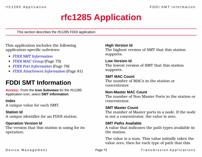
r f c 1 2 8 5 A p p l i c a t i o n F D D I S M T I n f o r m a t i o n
D e v i c e M a n a g e m e n t Page 73 T r a n s m i s s i o n A p p l i c a t i o n s
rfc1285 Application
This section describes the rfc1285 FDDI application.
This application includes the following application-specific subviews:
• FDDI SMT Information• FDDI MAC Group (Page 75)• FDDI Port Information (Page 78)• FDDI Attachment Information (Page 81)
FDDI SMT InformationAccess: From the Icon Subviews for the rfc1285 Application icon, select SMT Information.
IndexA unique value for each SMT.
Station IdA unique identifier for an FDDI station.
Operation Version IdThe version that this station is using for its operation.
High Version IdThe highest version of SMT that this station supports.
Low Version IdThe lowest version of SMT that this station supports.
SMT MAC CountThe number of MACs in the station or concentrator.
Non-Master MAC CountThe number of Non Master Ports in the station or concentrator.
SMT Master CountThe number of Master ports in a node. If the node is not a concentrator, the value is zero.
SMT Paths AvailableA value that indicates the path types available in the station.
The value is a sum. This value initially takes the value zero, then for each type of path that this
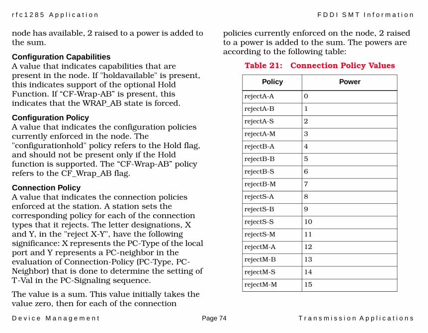
r f c 1 2 8 5 A p p l i c a t i o n F D D I S M T I n f o r m a t i o n
D e v i c e M a n a g e m e n t Page 74 T r a n s m i s s i o n A p p l i c a t i o n s
node has available, 2 raised to a power is added to the sum.
Configuration CapabilitiesA value that indicates capabilities that are present in the node. If "holdavailable" is present, this indicates support of the optional Hold Function. If “CF-Wrap-AB” is present, this indicates that the WRAP_AB state is forced.
Configuration PolicyA value that indicates the configuration policies currently enforced in the node. The "configurationhold" policy refers to the Hold flag, and should not be present only if the Hold function is supported. The “CF-Wrap-AB” policy refers to the CF_Wrap_AB flag.
Connection PolicyA value that indicates the connection policies enforced at the station. A station sets the corresponding policy for each of the connection types that it rejects. The letter designations, X and Y, in the "reject X-Y", have the following significance: X represents the PC-Type of the local port and Y represents a PC-neighbor in the evaluation of Connection-Policy (PC-Type, PC-Neighbor) that is done to determine the setting of T-Val in the PC-Signaling sequence.
The value is a sum. This value initially takes the value zero, then for each of the connection
policies currently enforced on the node, 2 raised to a power is added to the sum. The powers are according to the following table:
Table 21: Connection Policy Values
Policy Power
rejectA-A 0
rejectA-B 1
rejectA-S 2
rejectA-M 3
rejectB-A 4
rejectB-B 5
rejectB-S 6
rejectB-M 7
rejectS-A 8
rejectS-B 9
rejectS-S 10
rejectS-M 11
rejectM-A 12
rejectM-B 13
rejectM-S 14
rejectM-M 15

D e v i c e M a n a g e m e n t Page 75 T r a n s m i s s i o n A p p l i c a t i o n s
Implementors should note that the polarity of these bits is different in different places in an SMT system.
NotifyThe timer used in the Neighbor Notification protocol, reported in seconds and ranging from 2 to 30 seconds.
Status ReportingIndicates whether the node implements the Status Reporting Protocol. This field is included for compatibility with products that were designed prior to the adoption of this standard.
ECM StateThe current state of the ECM state machine.
CF StateThe attachment configuration for the station or concentrator.
Hold StateThis value indicates the current state of the Hold function. If the primary ring is operational and the Recovery Enable Flag is clear the value is "holding-prm."
Remote Disconnect FlagA flag indicating that the station was remotely disconnected from the network. A station requires a Connect Action to rejoin and clear the flag.
Station ActionThis field, when read, always returns a value of other. The result of setting this variable to any of the acceptable values is as follows:
FDDI MAC GroupAccess: From the Icon Subviews menu for the rfc1285 Application icon, select MAC Group.
NumberThe total number of MAC implementations (across all SMTs) on this network management application entity. The value for this variable
Table 22: Station Action Values
Value Result
Other A badValue error.
Connect Generates a connect request signal to CMT indicating that the ECM State machine is to begin a connection sequence.
Disconnect Generates a disconnect to ECM and sets the Disconnect Flag.
Path-Test Initiates a station path test. The Path-Test variable is set to Testing.
Self-Test Initiates a station self test.

r f c 1 2 8 5 A p p l i c a t i o n F D D I M A C G r o u p
D e v i c e M a n a g e m e n t Page 76 T r a n s m i s s i o n A p p l i c a t i o n s
must remain constant at least from one re-initialization of the entity’s network management system to the next re-initialization.
SMT IndexThe value of the SMT index associated with this MAC.
IndexA unique value for each MAC on the managed entity. The MAC identified by a particular value of this index is that identified by the same value of an ifindex object instance. That is, if a MAC is associated with the interface whose value of ifIndex in the Internet-Standard MIB is equal to 5, then the value of this MAC Index shall also equal 5. The value for each MAC must remain constant at least from one re-initialization of the entity’s network management system to the next re-initialization.
Frame Status CapabilitiesA value that indicates the MAC’s bridge and end-station capabilities for operating in a bridged FDDI network.
Max Greatest Lower BoundThe greatest lower bound of T_Max supported for this MAC.
TVX Greatest Lower BoundThe greatest lower bound of TVX supported for this MAC.
Paths AvailableA value that indicates the Path types available for this MAC.
Current PathIndicates the association of the MAC with a station Path.
Upstream NumberThe MAC’s upstream neighbor’s long individual MAC address. It may be determined by the Neighbor Information Frames protocol. The value shall be reported as "00 00 00 00 00 00" if it is unknown.
Old Upstream NumberThe previous value of the MAC’s upstream neighbor’s long individual MAC address. It may be determined by the Neighbor Information Frame protocol. The value shall be reported as "00 00 00 00 00 00" if it is unknown.
Duplicate Address TestThe Duplicate Address Test flag, Dup_Addr_Test.
Paths RequestedA value that indicates paths desired for this MAC. The value is a sum which represents the
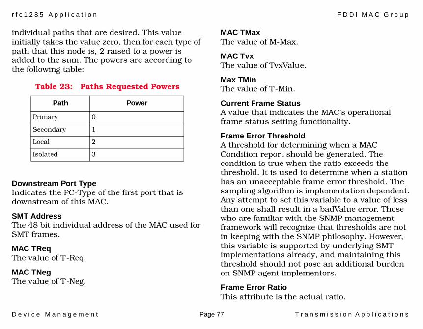
r f c 1 2 8 5 A p p l i c a t i o n F D D I M A C G r o u p
D e v i c e M a n a g e m e n t Page 77 T r a n s m i s s i o n A p p l i c a t i o n s
individual paths that are desired. This value initially takes the value zero, then for each type of path that this node is, 2 raised to a power is added to the sum. The powers are according to the following table:
Downstream Port TypeIndicates the PC-Type of the first port that is downstream of this MAC.
SMT AddressThe 48 bit individual address of the MAC used for SMT frames.
MAC TReqThe value of T-Req.
MAC TNegThe value of T-Neg.
MAC TMaxThe value of M-Max.
MAC TvxThe value of TvxValue.
Max TMinThe value of T-Min.
Current Frame StatusA value that indicates the MAC’s operational frame status setting functionality.
Frame Error ThresholdA threshold for determining when a MAC Condition report should be generated. The condition is true when the ratio exceeds the threshold. It is used to determine when a station has an unacceptable frame error threshold. The sampling algorithm is implementation dependent. Any attempt to set this variable to a value of less than one shall result in a badValue error. Those who are familiar with the SNMP management framework will recognize that thresholds are not in keeping with the SNMP philosophy. However, this variable is supported by underlying SMT implementations already, and maintaining this threshold should not pose an additional burden on SNMP agent implementors.
Frame Error RatioThis attribute is the actual ratio.
Table 23: Paths Requested Powers
Path Power
Primary 0
Secondary 1
Local 2
Isolated 3
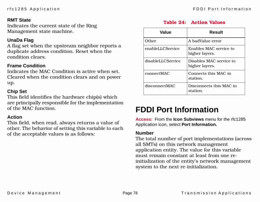
r f c 1 2 8 5 A p p l i c a t i o n F D D I P o r t I n f o r m a t i o n
D e v i c e M a n a g e m e n t Page 78 T r a n s m i s s i o n A p p l i c a t i o n s
RMT StateIndicates the current state of the Ring Management state machine.
UnaDa FlagA flag set when the upstream neighbor reports a duplicate address condition. Reset when the condition clears.
Frame ConditionIndicates the MAC Condition is active when set. Cleared when the condition clears and on power up.
Chip SetThis field identifies the hardware chip(s) which are principally responsible for the implementation of the MAC function.
ActionThis field, when read, always returns a value of other. The behavior of setting this variable to each of the acceptable values is as follows:
FDDI Port InformationAccess: From the Icon Subviews menu for the rfc1285 Application icon, select Port Information.
NumberThe total number of port implementations (across all SMTs) on this network management application entity. The value for this variable must remain constant at least from one re-initialization of the entity’s network management system to the next re-initialization.
Table 24: Action Values
Value Result
Other A badValue error
enableLLCService Enables MAC service to higher layers.
disableLLCService Disables MAC service to higher layers.
connectMAC Connects this MAC in station.
disconnectMAC Disconnects this MAC in station.
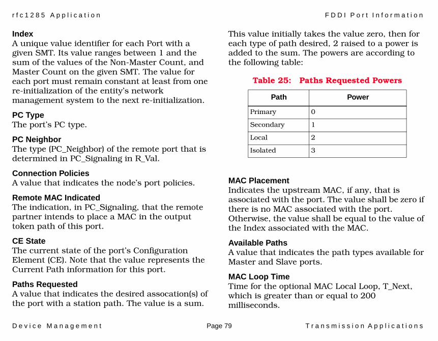
r f c 1 2 8 5 A p p l i c a t i o n F D D I P o r t I n f o r m a t i o n
D e v i c e M a n a g e m e n t Page 79 T r a n s m i s s i o n A p p l i c a t i o n s
IndexA unique value identifier for each Port with a given SMT. Its value ranges between 1 and the sum of the values of the Non-Master Count, and Master Count on the given SMT. The value for each port must remain constant at least from one re-initialization of the entity’s network management system to the next re-initialization.
PC TypeThe port’s PC type.
PC Neighbor The type (PC_Neighbor) of the remote port that is determined in PC_Signaling in R_Val.
Connection PoliciesA value that indicates the node’s port policies.
Remote MAC IndicatedThe indication, in PC_Signaling, that the remote partner intends to place a MAC in the output token path of this port.
CE StateThe current state of the port’s Configuration Element (CE). Note that the value represents the Current Path information for this port.
Paths RequestedA value that indicates the desired assocation(s) of the port with a station path. The value is a sum.
This value initially takes the value zero, then for each type of path desired, 2 raised to a power is added to the sum. The powers are according to the following table:
MAC PlacementIndicates the upstream MAC, if any, that is associated with the port. The value shall be zero if there is no MAC associated with the port. Otherwise, the value shall be equal to the value of the Index associated with the MAC.
Available PathsA value that indicates the path types available for Master and Slave ports.
MAC Loop TimeTime for the optional MAC Local Loop, T_Next, which is greater than or equal to 200 milliseconds.
Table 25: Paths Requested Powers
Path Power
Primary 0
Secondary 1
Local 2
Isolated 3

r f c 1 2 8 5 A p p l i c a t i o n F D D I P o r t I n f o r m a t i o n
D e v i c e M a n a g e m e n t Page 80 T r a n s m i s s i o n A p p l i c a t i o n s
BS FlagThe Break State.
LCT Failure CountThe count of the consecutive times the link confidence test (LCT) has failed during the connection management.
LER EstimateA long term average link error rate (LER). It ranges from 10**-4 to 10**-15 and is reported as the absolute value of the exponent of the estimate.
LEM Reject CountA link error monitoring (LEM) count of the times that a link has been rejected.
LEM CountThe aggregate link error monitor error count, set to zero only on station power up.
LER CutoffThe link error rate estimate at which a link connection will be broken. It ranges from 10**-4 to 10**-15 and is reported as the absolute value of the exponent.
LER AlarmThe link error rate estimate at which a link connection will generate an alarm. It ranges from
10**-4 to 10**-15 and is reported as the absolute value of the exponent of the estimate.
Connect StateAn indication of the connect state of this port.
PCM StateThe Physical Connection Management (PCM) State.
PC WithholdThe PC_Withhold state.
LER ConditionThis variable is set to true whenever the LER Estimate is less than or equal to LER Alarm.
Chip SetThis field identifies the hardware chips(s) which are principally responsible for the implementation of the port function.
ActionThis field, when read, always returns a value of other. The result of setting this variable to each of the acceptable values is as follows:
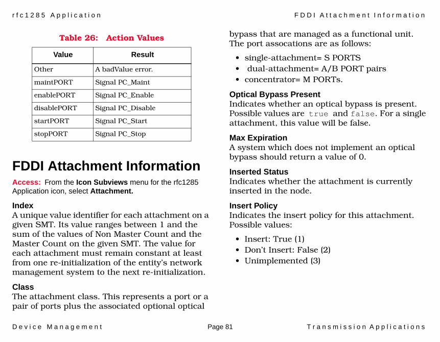
r f c 1 2 8 5 A p p l i c a t i o n F D D I A t t a c h m e n t I n f o r m a t i o n
D e v i c e M a n a g e m e n t Page 81 T r a n s m i s s i o n A p p l i c a t i o n s
FDDI Attachment InformationAccess: From the Icon Subviews menu for the rfc1285 Application icon, select Attachment.
IndexA unique value identifier for each attachment on a given SMT. Its value ranges between 1 and the sum of the values of Non Master Count and the Master Count on the given SMT. The value for each attachment must remain constant at least from one re-initialization of the entity’s network management system to the next re-initialization.
ClassThe attachment class. This represents a port or a pair of ports plus the associated optional optical
bypass that are managed as a functional unit. The port assocations are as follows:
• single-attachment= S PORTS• dual-attachment= A/B PORT pairs • concentrator= M PORTs.
Optical Bypass PresentIndicates whether an optical bypass is present. Possible values are true and false. For a single attachment, this value will be false.
Max ExpirationA system which does not implement an optical bypass should return a value of 0.
Inserted StatusIndicates whether the attachment is currently inserted in the node.
Insert PolicyIndicates the insert policy for this attachment. Possible values:
• Insert: True (1)• Don’t Insert: False (2)• Unimplemented (3)
Table 26: Action Values
Value Result
Other A badValue error.
maintPORT Signal PC_Maint
enablePORT Signal PC_Enable
disablePORT Signal PC_Disable
startPORT Signal PC_Start
stopPORT Signal PC_Stop
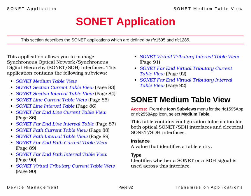
S O N E T A p p l i c a t i o n S O N E T M e d i u m T a b l e V i e w
D e v i c e M a n a g e m e n t Page 82 T r a n s m i s s i o n A p p l i c a t i o n s
SONET Application
This section describes the SONET applications which are defined by rfc1595 and rfc1285.
This application allows you to manage Synchronous Optical Network/Synchronous Digital Hierarchy (SONET/SDH) interfaces. This application contains the following subviews:
• SONET Medium Table View• SONET Section Current Table View (Page 83)• SONET Section Interval Table View (Page 84)• SONET Line Current Table View (Page 85)• SONET Line Interval Table (Page 86)• SONET Far End Line Current Table View
(Page 86)• SONET Far End Line Interval Table (Page 87)• SONET Path Current Table View (Page 88)• SONET Path Interval Table View (Page 89)• SONET Far End Path Current Table View
(Page 89)• SONET Far End Path Interval Table View
(Page 90)• SONET Virtual Tributary Current Table View
(Page 90)
• SONET Virtual Tributary Interval Table View (Page 91)
• SONET Far End Virtual Tributary Current Table View (Page 92)
• SONET Far End Virtual Tributary Interval Table View (Page 92)
SONET Medium Table ViewAccess: From the Icon Subviews menu for the rfc1595App or rfc2558App icon, select Medium Table.
This table contains configuration information for both optical SONET/SDH interfaces and electrical SONET/SDH interfaces.
InstanceA value that identifies a table entry.
TypeIdentifies whether a SONET or a SDH signal is used across this interface.
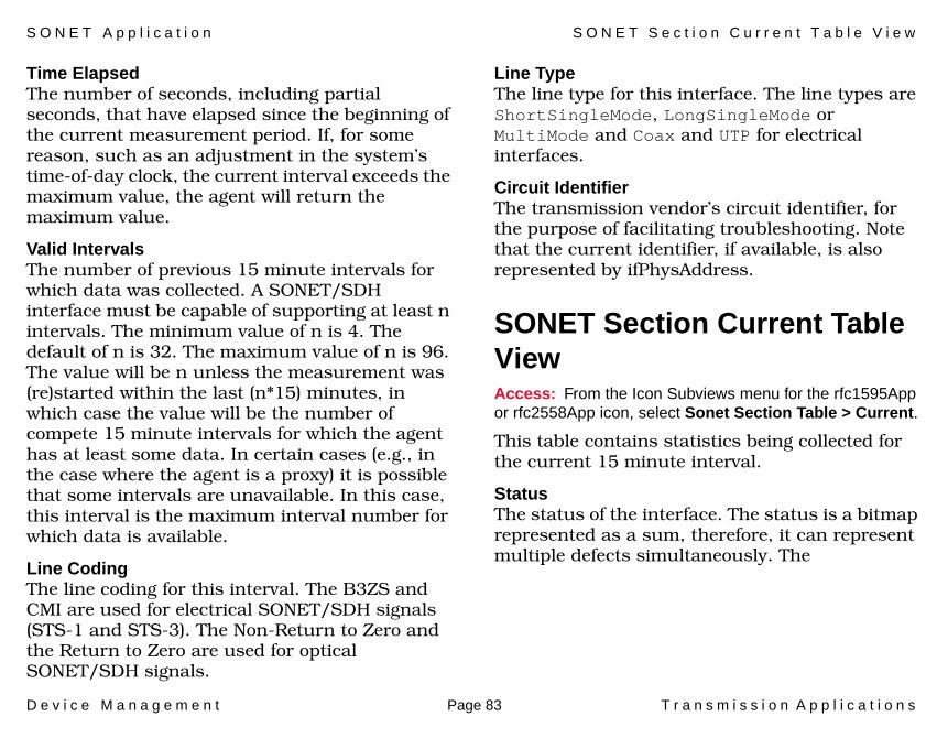
S O N E T A p p l i c a t i o n S O N E T S e c t i o n C u r r e n t T a b l e V i e w
D e v i c e M a n a g e m e n t Page 83 T r a n s m i s s i o n A p p l i c a t i o n s
Time ElapsedThe number of seconds, including partial seconds, that have elapsed since the beginning of the current measurement period. If, for some reason, such as an adjustment in the system’s time-of-day clock, the current interval exceeds the maximum value, the agent will return the maximum value.
Valid IntervalsThe number of previous 15 minute intervals for which data was collected. A SONET/SDH interface must be capable of supporting at least n intervals. The minimum value of n is 4. The default of n is 32. The maximum value of n is 96. The value will be n unless the measurement was (re)started within the last (n*15) minutes, in which case the value will be the number of compete 15 minute intervals for which the agent has at least some data. In certain cases (e.g., in the case where the agent is a proxy) it is possible that some intervals are unavailable. In this case, this interval is the maximum interval number for which data is available.
Line CodingThe line coding for this interval. The B3ZS and CMI are used for electrical SONET/SDH signals (STS-1 and STS-3). The Non-Return to Zero and the Return to Zero are used for optical SONET/SDH signals.
Line TypeThe line type for this interface. The line types are ShortSingleMode, LongSingleMode or MultiMode and Coax and UTP for electrical interfaces.
Circuit IdentifierThe transmission vendor’s circuit identifier, for the purpose of facilitating troubleshooting. Note that the current identifier, if available, is also represented by ifPhysAddress.
SONET Section Current Table ViewAccess: From the Icon Subviews menu for the rfc1595App or rfc2558App icon, select Sonet Section Table > Current.
This table contains statistics being collected for the current 15 minute interval.
StatusThe status of the interface. The status is a bitmap represented as a sum, therefore, it can represent multiple defects simultaneously. The
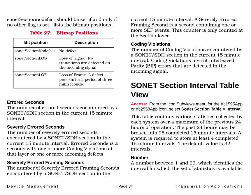
D e v i c e M a n a g e m e n t Page 84 T r a n s m i s s i o n A p p l i c a t i o n s
sonetSectionnodefect should be set if and only if no other flag is set. lists the bitmap positions.
Errored SecondsThe number of errored seconds encountered by a SONET/SDH section in the current 15 minute interval.
Severely Errored SecondsThe number of severely errored seconds encountered by a SONET/SDH section in the current 15 minute interval. Errored Seconds is a seconds with one or more Coding Violations at that layer or one or more incoming defects.
Severely Errored Framing SecondsThe number of Severely Errored Framing Seconds encountered by a SONET/SDH section in the
current 15 minute interval. A Severely Errored Framing Second is a second containing one or more SEF events. This counter is only counted at the Section layer.
Coding ViolationsThe number of Coding Violations encountered by a SONET/SDH section in the current 15 minute interval. Coding Violations are Bit Interleaved Parity (BIP) errors that are detected in the incoming signal.
SONET Section Interval Table ViewAccess: From the Icon Subviews menu for the rfc1595App or rfc2558App icon, select Sonet Section Table > Interval.
This table contains various statistics collected by each system over a maximum of the previous 24 hours of operation. The past 24 hours may be broken into 96 completed 15 minute intervals. A system is required to store at least 4 completed 15 minute intervals. The default value is 32 intervals.
NumberA number between 1 and 96, which identifies the interval for which the set of statistics is available.
Table 27: Bitmap Positions
Bit position Description
sonetSectionNodefect No defect
sonetSectionLOS Loss of Signal. No transitions are detected on the incoming signal.
sonetSectionLOF Loss of Frame. A defect persists for a period of three milliseconds.

S O N E T A p p l i c a t i o n S O N E T L i n e C u r r e n t T a b l e V i e w
D e v i c e M a n a g e m e n t Page 85 T r a n s m i s s i o n A p p l i c a t i o n s
The interval identified by 1 is the most recently completed 15 minute interval.
Errored SecondsThe number of Errored Seconds encountered by a SONET/SDH section in a particular 15 minute interval in the past 24 hours.
Severely Errored SecondsThe number of Severely Errored Seconds encountered by a SONET/SDH section in a particular 15 minute interval in the past 24 hours.
Severely Errored Framing SecondsThe number of Severely Errored Framing Seconds encountered by a SONET/SDH section in a particular 15 minute interval during the past 24 hours.
Coding ViolationsThe number of Coding Violations encountered by a SONET/SDH section in a particular 15 minute interval in the past 24 hours.
Valid DataIndicates if the data for this interval is valid.
SONET Line Current Table ViewAccess: From the Icon Subviews menu for the rfc1595App or rfc2558App icon, select Sonet Line Table > Current.
InstanceA unique value for an entry in the table.
StatusThe status of the interface is a bitmap represented as a sum. Table 28 lists the possible bitmap positions.
Errored SecondsThe number of errored seconds encountered by a SONET/SDH Line in the current 15 minute interval.
Table 28: Line Bitmap Positions
Bitmap Description
sonetLineNoDefect No defect-no other flag is set.
sonetLineAIS Alarm Indication Signal
sonetLineRDI Remote Defect Indication
S O N E T A p p l i c a t i o n S O N E T L i n e I n t e r v a l T a b l e
D e v i c e M a n a g e m e n t Page 86 T r a n s m i s s i o n A p p l i c a t i o n s
Severely Errored SecondsThe number of severely errored seconds encountered by a SONET/SDH Line in the current 15 minute interval.
Coding ViolationsThe number of Coding Violations encountered by a SONET/SDH Line in the current 15 minute interval.
Unavailable SecondsThe number of Unavailable Seconds encountered by a SONET/SDH Line in the current 15 minute interval. At the Line, Path, and VT layers, an unavailable second is calculated by counting the number of seconds that the interface is unavailable.
SONET Line Interval TableAccess: From the Icon Subviews menu for the rfc1595App or rfc2558App icon, select Sonet Line Table > Interval.
InstanceA number between 1 and 96, which identifies the interval for which the set of statistics is available.
Errored SecondsThe number of Errored Seconds encountered by a SONET/SDH Line in a particular 15 minute interval in the past 24 hours.
Severely Errored SecondsThe number of Severely Errored Seconds encountered by a SONET/SDH Line in a particular 15 minute interval in the past 24 hours.
Coding ViolationsThe number of Coding Violations encountered by a SONET/SDH Line in a particular 15 minute interval in the past 24 hours.
Valid DataIndicates if the data for this interval is valid.
SONET Far End Line Current Table ViewAccess: From the Icon Subviews menu for the rfc1595App or rfc2558App icon, select Sonet Far End Line Table > Current.
This group may only be implemented by SONET systems that provide for far end block error (FEBE) information at the SONET/SDH Line Layer.
This table contains various statistics being collected for the current 15 minute interval. The statistics are collected from the far end block error code (FEBE) within the third Z2 byte of the line overhead in Broadband ISDN applications.

S O N E T A p p l i c a t i o n S O N E T F a r E n d L i n e I n t e r v a l T a b l e
D e v i c e M a n a g e m e n t Page 87 T r a n s m i s s i o n A p p l i c a t i o n s
InstanceA unique value for an entry in the table.
Errored SecondsThe number of errored seconds encountered by a SONET/SDH Line in the current 15 minute interval.
Severely Errored SecondsThe number of severely errored seconds encountered by a SONET/SDH Line in the current 15 minute interval.
SEFSsThe number of Severely Errored Framing Seconds encountered by a SONET/SDH Line in the current 15 minute interval.
Coding ViolationsThe number of Coding Violations encountered by a SONET/SDH Line in the current 15 minute interval.
Unavailable SecondsThe number of Unavailable Seconds encountered by a SONET/SDH Line in the current 15 minute interval.
SONET Far End Line Interval TableAccess: From the Icon Subviews menu for the rfc1595App or rfc2558App icon, select Sonet Far End Line Table > Interval.
InstanceA unique value for an entry in the table.
Errored SecondsThe number of errored seconds encountered by a SONET/SDH Line interface in a particular 15 minute interval in the past 24 hours.
Severely Errored SecondsThe number of Far End severely errored seconds encountered by a SONET/SDH Line in a particular 15 minute interval in the past 24 hours.
Coding ViolationsThe number of Far End Coding Violations reported via the block end error count encountered by a SONET/SDH Line interface in a particular 15 minute interval during the past 24 hours.

S O N E T A p p l i c a t i o n S O N E T P a t h C u r r e n t T a b l e V i e w
D e v i c e M a n a g e m e n t Page 88 T r a n s m i s s i o n A p p l i c a t i o n s
Unavailable SecondsThe number of Unavailable Seconds encountered by a SONET/SDH Line in a particular 15 minute interval during the past 24 hours.
SONET Path Current Table ViewAccess: From the Icon Subviews menu for the rfc1595App or rfc2558App icon, select Sonet Path Table > Current.
InstanceA unique value for an entry in the table.
WidthIndicates the type of the SONET/SDH Path. For SONET, the assigned types are the STS-Nc SPEs, where N=1, 3, 12, 24, and 48. STS-1 is equal to 51.84 Mbps. For SDH, the assigned types are the STM-Nc VCs, where N=1, 4, and 16.
StatusThe status of the interface which is a bitmap represented as a sum. Table 29 lists the bit map positions.
Errored SecondsThe number of Errored Seconds encountered by a SONET/SDH Path in the current 15 minute interval.
Severely Errored SecondsThe number of Severely Errored Seconds encountered by a SONET/SDH Path in the current 15 minute interval.
Coding ViolationsThe number of coding violations encountered by a SONET/SDH path in the current 15 minute interval.
Table 29: Path Bit Definitions
Bit position Description
sonetPathNodefect No defect detected.
sonetPathSTSLOP Loss of Pointer
sonetPathSTSAIS Alarm Indication Signal
sonetPathSTSRDI Remote Defect Indication
sonetPathUnequipped Path is idle.
sonetPathSignalLabelMismatch Signal Label Mismatch
S O N E T A p p l i c a t i o n S O N E T P a t h I n t e r v a l T a b l e V i e w
D e v i c e M a n a g e m e n t Page 89 T r a n s m i s s i o n A p p l i c a t i o n s
Unavailable SecondsThe number of unavailable seconds encountered by a Path in the current 15 minute interval.
SONET Path Interval Table ViewAccess: From the Icon Subviews menu for the rfc1595App or rfc2558App icon, select Sonet Path Table > Interval.
InstanceA unique value for an entry in the table.
Errored SecondsThe number of Errored Seconds encountered by a SONET/SDH Path in a particular 15 minute interval during the past 24 hours.
Severely Errored SecondsThe number of Severely Errored Seconds encountered by a SONET/SDH Path in a particular 15 minute interval during the past 24 hours.
Coding ViolationsThe number of coding violations encountered by a SONET/SDH path in a particular 15 minute interval during the past 24 hours.
Unavailable SecondsThe number of unavailable seconds encountered by a Path in a particular 15 minute interval during the past 24 hours.
SONET Far End Path Current Table ViewAccess: From the Icon Subviews menu for the rfc1595App or rfc2558App icon, select Sonet Far End Path Table > Current.
InstanceA unique value for an entry in the table.
Errored SecondsThe number of Errored Seconds encountered by a SONET/SDH Far End Path in the current 15 minute interval.
Severely Errored SecondsThe number of Far End Path Severely Errored Seconds encountered by a SONET/SDH Path in the current 15 minute interval.
Coding ViolationsThe number of Far End coding violations encountered by a SONET/SDH path in the current 15 minute interval.

S O N E T A p p l i c a t i o n S O N E T F a r E n d P a t h I n t e r v a l T a b l e V i e w
D e v i c e M a n a g e m e n t Page 90 T r a n s m i s s i o n A p p l i c a t i o n s
Unavailable SecondsThe number of Far End unavailable seconds encountered by a Path in the current 15 minute interval.
SONET Far End Path Interval Table ViewAccess: From the Icon Subviews menu for the rfc1595App or rfc2558App icon, select Sonet Far End Path Table > Interval.
InstanceA unique value for an entry in the table.
Errored SecondsThe number of Errored Seconds encountered by a SONET/SDH Far End Path in a particular 15 minute interval during the past 24 hours.
Severely Errored SecondsThe number of Far End Path Severely Errored Seconds encountered by a SONET/SDH Path in a particular 15 minute interval during the past 24 hours.
Coding ViolationsThe number of Far End coding violations encountered by a SONET/SDH path in a particular 15 minute interval during the past 24 hours.
Unavailable SecondsThe number of Far End unavailable seconds encountered by a Path in a particular 15 minute interval during the past 24 hours.
SONET Virtual Tributary Current Table ViewAccess: From the Icon Subviews menu for the rfc1595App or rfc2558App icon, select Sonet VT Table > Current.
InstanceA unique value for an entry in the table.
WidthIndicates the type of the SONET/SDH Virtual Tributary (VT).
StatusThe status of the interface which is a bit position represented as a sum. Table 30 lists the bit map positions.
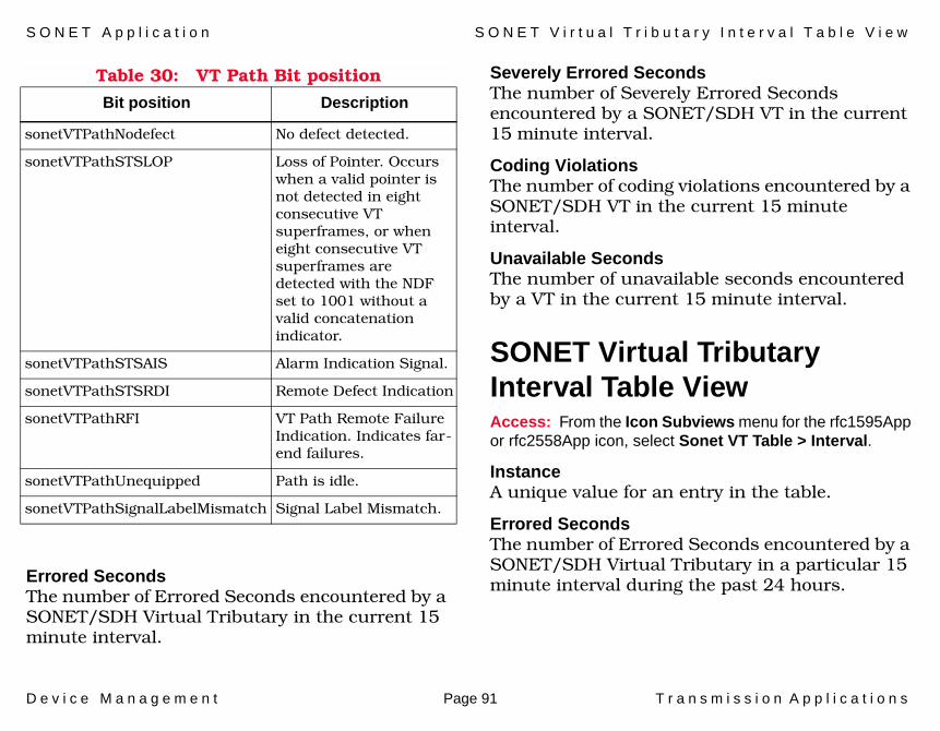
S O N E T A p p l i c a t i o n S O N E T V i r t u a l T r i b u t a r y I n t e r v a l T a b l e V i e w
D e v i c e M a n a g e m e n t Page 91 T r a n s m i s s i o n A p p l i c a t i o n s
Table 30: VT Path Bit position
Errored SecondsThe number of Errored Seconds encountered by a SONET/SDH Virtual Tributary in the current 15 minute interval.
Severely Errored SecondsThe number of Severely Errored Seconds encountered by a SONET/SDH VT in the current 15 minute interval.
Coding ViolationsThe number of coding violations encountered by a SONET/SDH VT in the current 15 minute interval.
Unavailable SecondsThe number of unavailable seconds encountered by a VT in the current 15 minute interval.
SONET Virtual Tributary Interval Table ViewAccess: From the Icon Subviews menu for the rfc1595App or rfc2558App icon, select Sonet VT Table > Interval.
InstanceA unique value for an entry in the table.
Errored SecondsThe number of Errored Seconds encountered by a SONET/SDH Virtual Tributary in a particular 15 minute interval during the past 24 hours.
Bit position Description
sonetVTPathNodefect No defect detected.
sonetVTPathSTSLOP Loss of Pointer. Occurs when a valid pointer is not detected in eight consecutive VT superframes, or when eight consecutive VT superframes are detected with the NDF set to 1001 without a valid concatenation indicator.
sonetVTPathSTSAIS Alarm Indication Signal.
sonetVTPathSTSRDI Remote Defect Indication
sonetVTPathRFI VT Path Remote Failure Indication. Indicates far-end failures.
sonetVTPathUnequipped Path is idle.
sonetVTPathSignalLabelMismatch Signal Label Mismatch.

S O N E T A p p l i c a t i o n S O N E T F a r E n d V i r t u a l T r i b u t a r y C u r r e n t T a b l e V i e w
D e v i c e M a n a g e m e n t Page 92 T r a n s m i s s i o n A p p l i c a t i o n s
Severely Errored SecondsThe number of Severely Errored Seconds encountered by a SONET/SDH VT in a particular 15 minute interval during the past 24 hours.
Coding ViolationsThe number of coding violations encountered by a SONET/SDH VT in a particular 15 minute interval during the past 24 hours.
Unavailable SecondsThe number of unavailable seconds encountered by a VT in a particular 15 minute interval during the past 24 hours.
SONET Far End Virtual Tributary Current Table ViewAccess: From the Icon Subviews menu for the rfc1595App or rfc2558App icon, select Sonet Far End VT Table > Current.
InstanceA unique value for an entry in the table.
Errored SecondsThe number of Errored Seconds encountered by a SONET/SDH Far End Virtual Tributary in the current 15 minute interval.
Severely Errored SecondsThe number of Severely Errored Seconds encountered by a SONET/SDH Far End VT in the current 15 minute interval.
Coding ViolationsThe number of coding violations encountered by a SONET/SDH Far End VT in the current 15 minute interval.
Unavailable SecondsThe number of unavailable seconds encountered by a Far End VT in the current 15 minute interval.
SONET Far End Virtual Tributary Interval Table ViewAccess: From the Icon Subviews menu for the rfc1595App or rfc2558App icon, select Sonet Far End VT Table > Interval.
InstanceA unique value for an entry in the table.
Errored SecondsThe number of Errored Seconds encountered by a SONET/SDH Far End Virtual Tributary in the current 15 minute interval.
S O N E T A p p l i c a t i o n S O N E T F a r E n d V i r t u a l T r i b u t a r y I n t e r v a l T a b l e V i e w
D e v i c e M a n a g e m e n t Page 93 T r a n s m i s s i o n A p p l i c a t i o n s
Severely Errored SecondsThe number of Severely Errored Seconds encountered by a SONET/SDH Far End VT in the current 15 minute interval.
Coding ViolationsThe number of coding violations encountered by a SONET/SDH Far End VT in the current 15 minute interval.
Unavailable SecondsThe number of unavailable seconds encountered by a Far End VT in the current 15 minute interval.

r f c 2 1 1 5 A p p
D e v i c e M a n a g e m e n t Page 94 T r a n s m i s s i o n A p p l i c a t i o n s
rfc2115App
This section provides descriptions of the rfc2115App Views and the rfc2115app MIB objects.
rfc2115App ViewsThis section describes the views available for the rfc2115App application. There are three application-specific subviews available from the Icon Subviews menu:
• Frame Relay Circuit Table (Figure 1 on Page 95)
• Data Link Connection Management Table view (Figure 2 on Page 98)
• Error Table view (Figure 3 on Page 100)

r f c 2 1 1 5 A p p r f c 2 1 1 5 A p p V i e w s
D e v i c e M a n a g e m e n t Page 95 T r a n s m i s s i o n A p p l i c a t i o n s
Frame Relay Circuit TableAccess: From the Icon Subviews menu for the rfc2115App icon, select Circuit Table.
This table (Figure 1) contains information about specific Data Link Connections or virtual circuits.The data in this table comes from the frCircuitTable object in the rfc2115 MIB.
Figure 1: Frame Relay Circuit Table

D e v i c e M a n a g e m e n t Page 96 T r a n s m i s s i o n A p p l i c a t i o n s
IndexThe ifIndex value of the corresponding ifEntry.
DLCIThe Data Link Connection Identifier for this virtual circuit.
StateThis variable indicates whether the particular virtual circuit is operational.
Received FECNsThe number of frames received from the network indicating forward congestion since the virtual circuit was created.
Received BECNsThe number of frames received from the network indicating backward congestion since the virtual circuit was created.
Frames SentThe number of frames sent from this virtual circuit since it was created.
Octets SentThe number of octets sent from this virtual circuit since it was created.
Frames ReceivedThe number of frames received over this virtual circuit since it was created.
Octets ReceivedThe number of octets received over this virtual circuit since it was created.
Creation TimeThe value of sysUpTime when the virtual circuit was created, whether by the Data Link Connection Management Interface or by a SetRequest.
Last ChangeThe value of sysUpTime at the last change in the virtual circuit state.
Committed Burst This variable indicates the maximum amount of data, in bits, that the network agrees to transfer under normal conditions, during the measurement interval.
Excess Burst This variable indicates the maximum amount of uncommitted data bits that the network will attempt to deliver over the measurement interval.
Throughput Throughput is the average number of 'Frame Relay Information Field' bits transferred per second across a user network interface in one direction, measured over the measurement interval.

r f c 2 1 1 5 A p p r f c 2 1 1 5 A p p V i e w s
D e v i c e M a n a g e m e n t Page 97 T r a n s m i s s i o n A p p l i c a t i o n s
Multicast This indicates either that the VC is unicast (i.e. not multicast), or the type of multicast service subscribed to.
Type Indication of whether the VC was manually created (static), or dynamically created (dynamic) via the data link control management interface.
Discards The number of inbound frames dropped because of format errors, or because the VC is inactive.
Received DEs The number of inbound frames dropped because of format errors, or because the VC is inactive.
Sent DEsThe number of frames sent to the network indicating that they were eligible for discard since the virtual circuit was created.
Logical IndexThis field normally has the same value as the IF Index. It has a different value when an implementation associates a virtual ifEntry with a DLC or set of DLCs, in order to associate higher layer objects.
Row Status This object is used to create a new row or modify or destroy an existing row, in the manner described in the definition of the RowStatus textual convention.

r f c 2 1 1 5 A p p r f c 2 1 1 5 A p p V i e w s
D e v i c e M a n a g e m e n t Page 98 T r a n s m i s s i o n A p p l i c a t i o n s
Frame Relay Data Link Connection Management TableAccess: From the Icon Subviews menu for the rfc2115App icon, select DLCMI Table.
This view (Figure 2) provides information about the management configuration of each Frame Relay DLCI on a device. The data in this table comes from the frDlcmiTable object in the rfc2115 MIB.
Figure 2: Frame Relay Data Link Connection Management Table

r f c 2 1 1 5 A p p r f c 2 1 1 5 A p p V i e w s
D e v i c e M a n a g e m e n t Page 99 T r a n s m i s s i o n A p p l i c a t i o n s
IndexThe ifIndex value of the corresponding ifEntry.
StateThis variable states which Data Link Connection Management scheme is active (and by implication, what DLCI it uses) on the Frame Relay interface.
Address FormatThis variable states which address format is in use on the Frame Relay interface.
Address LengthThis variable states the address length in octets.
Polling IntervalThis is the number of seconds between successive status enquiry messages.
Enquiry IntervalThis is the number of status enquiry intervals that pass before issuance of a full status enquiry message.
Error Threshold This is the maximum number of unanswered Status Enquiries the equipment shall accept before declaring the interface down.
Monitored Events This is the number of status polling intervals over which the error threshold is counted.
Max Supported VCsThis is the maximum number of Virtual Circuits allowed for this interface. This number is usually dictated by the Frame Relay network.
Multicast This indicates whether the Frame Relay interface is using a multicast service.
Status This indicates the status of the Frame Relay interface as determined by the performance of the DLCMI.
Row Status This is the SNMP Version 2 Row Status Variable.
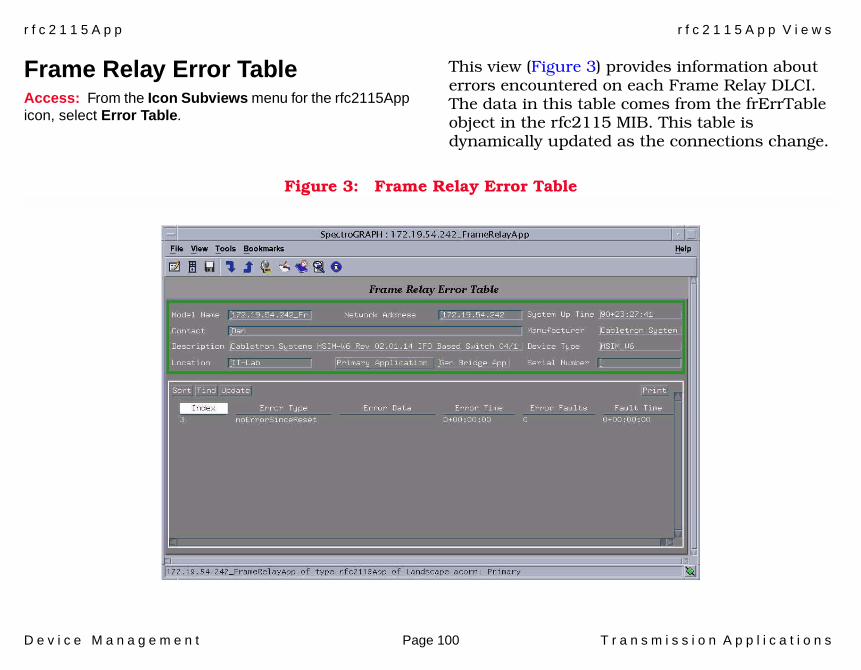
r f c 2 1 1 5 A p p r f c 2 1 1 5 A p p V i e w s
D e v i c e M a n a g e m e n t Page 100 T r a n s m i s s i o n A p p l i c a t i o n s
Frame Relay Error TableAccess: From the Icon Subviews menu for the rfc2115App icon, select Error Table.
This view (Figure 3) provides information about errors encountered on each Frame Relay DLCI. The data in this table comes from the frErrTable object in the rfc2115 MIB. This table is dynamically updated as the connections change.
Figure 3: Frame Relay Error Table

r f c 2 1 1 5 A p p r f c 2 1 1 5 A p p V i e w s
D e v i c e M a n a g e m e n t Page 101 T r a n s m i s s i o n A p p l i c a t i o n s
Index The ifIndex value of the corresponding ifEntry.
Error Type The type of error that was last seen on this interface. Table 31 shows the possible error types.
Table 31: Possible Error Types
Error Description
receiveShort Frame was not long enough to allow demultiplexing - the address field was incomplete, or for virtual circuits using Multiprotocol over Frame Relay, the protocol identifier was missing or incomplete.
receiveLong Frame exceeded the maximum length configured for this interface.
illegalAddress Address field did not match configured format.
unknownAddress Frame received on a virtual circuit that was not active or administratively disabled.
dlcmiProtoErr Unspecified error occurred when attempting to interpret the link maintenance frame.
dlcmiUnknownIE Link maintenance frame contained an Information Element type which is not valid for the configured link maintenance protocol.
dlcmiSequenceErr Link maintenance frame contained a sequence number other than the expected value.
dlcmiUnknownRpt Link maintenance frame contained a Report Type Information Element whose value was not valid for the configured link maintenance protocol.
noErrorSinceReset No errors have been detected since the last cold start or warm start.
Table 31: Possible Error Types
Error Description

r f c 2 1 1 5 A p p r f c 2 1 1 5 A p p V i e w s
D e v i c e M a n a g e m e n t Page 102 T r a n s m i s s i o n A p p l i c a t i o n s
Error Data This contains an octet string containing as much of the error packet as possible.
Error TimeThis is the value of sysUpTime at which the error was detected.
Error FaultsThis is the number of times the interface has gone down since it was initialized.
Fault TimeThis is the value of sysUpTime at the time when the interface was taken down due to excessive errors.
R F C 2 6 6 7 A p p
D e v i c e M a n a g e m e n t Page 103 T r a n s m i s s i o n A p p l i c a t i o n s
RFC2667App
This section describes the IP Tunnel MIB application (RFC2667App).
RFC2667AppThis section describes the views available for the RFC2667App application. There are two application-specific subviews available from the Icon Subviews menu:
• Tunnel Interface Table• Tunnel Configuration Table (Page 105)
Tunnel Interface TableAccess: From the Icon Subviews menu for the RFC2667App icon, select Tunnel Interface Table.
This table contains information on configured IP tunnels. Double-clicking an entry in this table opens a Tunnel Interface Entry view for that entry. The following information is provided.
Local AddressThe address of the local endpoint of the tunnel (i.e., the source address used in the outer IP header), or 0.0.0.0 if unknown.
Remote AddressThe address of the remote endpoint of the tunnel (i.e., the destination address used in the outer IP header), or 0.0.0.0 if unknown.
Hop LimitThe TTL to use in the outer IP header. A value of 0 indicates that the value is copied from the payload's header.
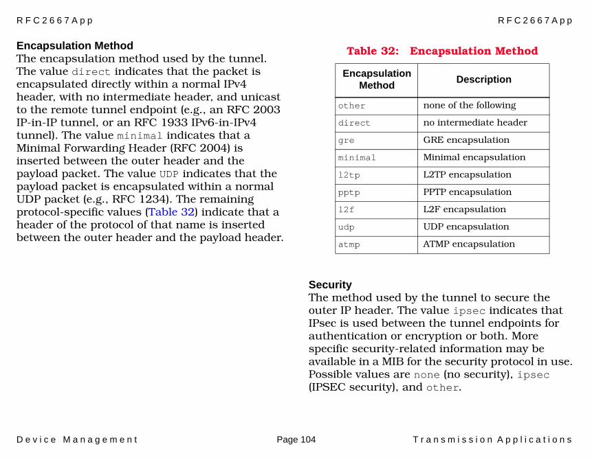
R F C 2 6 6 7 A p p R F C 2 6 6 7 A p p
D e v i c e M a n a g e m e n t Page 104 T r a n s m i s s i o n A p p l i c a t i o n s
Encapsulation Method The encapsulation method used by the tunnel. The value direct indicates that the packet is encapsulated directly within a normal IPv4 header, with no intermediate header, and unicast to the remote tunnel endpoint (e.g., an RFC 2003 IP-in-IP tunnel, or an RFC 1933 IPv6-in-IPv4 tunnel). The value minimal indicates that a Minimal Forwarding Header (RFC 2004) is inserted between the outer header and the payload packet. The value UDP indicates that the payload packet is encapsulated within a normal UDP packet (e.g., RFC 1234). The remaining protocol-specific values (Table 32) indicate that a header of the protocol of that name is inserted between the outer header and the payload header.
SecurityThe method used by the tunnel to secure the outer IP header. The value ipsec indicates that IPsec is used between the tunnel endpoints for authentication or encryption or both. More specific security-related information may be available in a MIB for the security protocol in use. Possible values are none (no security), ipsec (IPSEC security), and other.
Table 32: Encapsulation Method
Encapsulation Method Description
other none of the following
direct no intermediate header
gre GRE encapsulation
minimal Minimal encapsulation
l2tp L2TP encapsulation
pptp PPTP encapsulation
l2f L2F encapsulation
udp UDP encapsulation
atmp ATMP encapsulation
D e v i c e M a n a g e m e n t Page 105 T r a n s m i s s i o n A p p l i c a t i o n s
TOSThe method used to set the high 6 bits of the TOS in the outer IP header. A value of -1 indicates that the bits are copied from the payload's header. A value of -2 indicates that a traffic conditioner is invoked and more information may be available in a traffic conditioner MIB. A value between 0 and 63 inclusive indicates that the bit field is set to the indicated value.
Tunnel Configuration TableAccess: From the Icon Subviews menu for the RFC2667App icon, select Tunnel Configuration Table.
This table can be used to map a set of tunnel endpoints to the associated ifIndex value. It can also be used for row creation. Note that every row in the Tunnel Interface Table (Page 103) with a fixed destination address should have a corresponding row in this table, regardless of whether it was created via SNMP. This table provides the following information.
Local AddressThe address of the local endpoint of the tunnel, or 0.0.0.0 if the device is free to choose any of its addresses at tunnel establishment time.
Remote AddressThe address of the remote endpoint of the tunnel.
Encapsulation MethodThe encapsulation method used by the tunnel. See Encapsulation Method and Table 32 (Page 104).
IDAn identifier used to distinguish between multiple tunnels of the same encapsulation method, with the same endpoints.
IF IndexIf the value of Status for this row is active, then this contains the value of ifIndex corresponding to the tunnel interface. A value of 0 is not legal in the active state, and means that the interface index has not yet been assigned.
StatusThe status of this row, by which new entries may be created, or old entries deleted from this table.

D e v i c e M a n a g e m e n t Page 106 T r a n s m i s s i o n A p p l i c a t i o n s
110
Index
AA/C 49Abort Trans 50Aborted Frames 39ACC Map 20Active Monitor Process 51Address
DLCM 70Alignment 54Antenna Information 62Association/Disassociation 57Asynchronous Control Character
(ACC) Map 21Authentication 58AutoBaud 40Auto-RemovalError 52
BBad Addresses 22Bad Controls 22Bad FCSs 22BECNs 71BSS 56Burst 49Burst Information 72
CC_wrap_s 13Carrier Sense 54C-bit Information 32CCVs 33, 34CESs 33, 34CF State 12CFP 56Changes 38Check 12Circuit
Number 45, 47Clear To Send 38Clear to Send 36ClockSrc 38Commands 51Compression 44Concatenated 15Configuration
DS3/E3 30Congestion 46, 48Congestions 50Connect 14Counters 58CRC Length 44Create Interface Applications 54CSEs 33, 34
CtWANApp Icon 42CtWANAppRS232 35
Ddata 35Data Bits 40data circuit-terminating 35Data Link Connection 69Data Link, VC Information 71Data Rate 57Data Set Ready 36, 38data terminal equipment 35DCE 35Deauthentication 57Defer Trans 53Deinsert 12DLCM Status 69Double Click For 43Downstream Port Type 15DS1 Application 23, 30DSIAPP1406 23DSIAPP1406 Application 23
DSI Fractional Table 28DSSS 63DTE 35DTIM 56, 57
I n d e x I n d e x
D e v i c e M a n a g e m e n t Page 107 T r a n s m i s s i o n A p p l i c a t i o n s
EEncapsulation Method 104Enquiry Interval 70Entry Index 44Error Breakdown 39, 41Error Table view 94Error Threshold 70Errors 16Errors, Frame Relay 69Ethernet Application Configuration
View 54EthernetIfApps 54Excess Coll 54Excess Defer 54
FFacilities Data Link Codes 27FCS 53FCS Size 20, 21FDDI Application 8FDDI Station List View 8FddiSMT 8FECNs 71FHSS 63Format Errors 16Frame Check Errors 39Frame Check Sequence 20, 21Frame Copied 50Frame Count 58
Frame Length 53Frame Relay 45
Application Views 45Circuit Detail View 45
Frame Relay Information 69Frames
Copied 15Discarded 46Received 15Transmitted 15
Frames Sent, Received 71Framing Errors 40, 41Frequency 50Functional Address Bitmask 51
HHard Errors Breakdown 50HardError 52Hardware Present 17HDLC 21HiVersionId 10
IIF Index 19If Index 44In 11In Signals 36In Speed 35
Index 10In-Range 53Insert 12Internal 50Interrupted Frames 39IP Tunnel MIB 103Isolating Soft Errors Breakdown 49
LLate Coll 54LCP configuration parameters 19LCVs 33, 34Leave 12LESs 33, 34Line 49Line Code Violations 32Line Coding 44Line Status 31Line Statuses 26Line Type 23, 30Lobe Wire 50LobeWireFault 52Local MRU 20Local to Remote Configuration 19Local_a 12Local_ab 12Local_b 12Loopback Configuration 31Loopback Configurations 25Lost Frames 50

I n d e x I n d e x
D e v i c e M a n a g e m e n t Page 108 T r a n s m i s s i o n A p p l i c a t i o n s
LoVersionId 10Lower Layer Index 45, 47
MMAC
Cts 11If Index 14Index 14Path 14Table View 14
MAC Receive 54MAC Transmit 54Master Cts 11Master Ports 9Maximum Receive Unit (MRU) 21Monitored Events 70MTU 44Multi Coll 53Multicast 45, 47, 70
NNear End Intervals 30Node Class 8Non Master Cts 11Non-Isolating Soft Errors
Breakdown 50Notify 11
OOccupancy Limit 56Octets Sent, Received 71OpVersionId 10Out 11Out Signals 36Out Speed 36Out-Range 54Overrun Errors 41
PPacket Too Longs 22Parity 40, 41
Errors 40, 41Path_Test 12P-bit Information 32PCVs 32, 33, 34Peer Wrap 13PESs 32, 33Physical Index 19, 20Physical Port 44Polling Interval 70Port ID 37, 38, 40Port Index 35, 43Port Type 35PPP Link Status Performance
View 21Primary 15Privacy 56
Protocol 44PSEs 32, 33
QQ921,Q922 70
RRcv. Overrun Errors 39Recoveries 50Remote
Disconnect 13Remote MRU 21Remove Ring Station Count 49RemoveReceived 52rfc2667App 103Ring
Management State 16Ring Open-Status 51Ring Speed 51Ring State 51Ring Status 51Ring Topology 9RingRecovery 52RS 41RS232
ViewsAsynchronous Port Detail 41Port Input Signals Table 36

I n d e x I n d e x
D e v i c e M a n a g e m e n t Page 109 T r a n s m i s s i o n A p p l i c a t i o n s
Port Output Signals Table 37Port Table 35Port Table Configuration 36Synchronous 38Synchronous Port Table 38
RS-232 Applications. 35RS232 Port Table 35
SSEFs 32, 34Send Codes 25serial point-to-point links 18Signal Loss 50Signal Modes 27Signal Name 37SignalLoss 52Single Coll 53SingleStation 52SMT
Index 14Station Table 10
SMT Configuration 55Soft Error Count 49SoftError 52SSID 56State 38Station
Action 13Status 13Table View 10
Station Address 8Statistics
DS3/E3 33, 34Frame Relay 69
StatRptPolicy 11Stop Bits 40, 41Synchronous Port Detail View 39
TThreshold 16Threshold Information 69Thresholds 60Throughput 72Time
Stamp 13Time Elapsed 30T-Max Value 15Token 50Token Ring
Views 49Detail 49IF 51IF Configuration 51
Token Ring Application 49Trace 12TraceMaxExpiration 11TransitionTimeStamp 13Transmit
Fail Errors Pie Chart 54Transmit Clock Source 32
Transmit Clock Sources 27TransmitBeacon 52Transmitted Beacon Count 49TVX Value 15Type 43
UUASs 32, 33, 34Up Stream Neighbor 51Upstream Neighbor 9
VVC Creation Time 71VC Information 70VC State 71Virtual Circuit
Address 47Mode 46, 48State 47Type 46, 48
WWAN 42
ViewsConnection Interface
Table 44

I n d e x I n d e x
D e v i c e M a n a g e m e n t Page 110 T r a n s m i s s i o n A p p l i c a t i o n s
WAN Connection 44Watchdog Timer 64Wide Area Network 42Wrap_a 12Wrap_b 12Wrap_s 13
XXmt. Underrun Errors 39
ZZero Code Suppression 31Zero Codes 24