getting started - websense
TRANSCRIPT
Getting Started
v7.7.x
Websense® V-Series Appl ianceV10000, V10000 G2, V10000 G3, and V5000 G2

©1996–2013, Websense, Inc.10240 Sorrento Valley Rd., San Diego, CA 92121, USAAll rights reserved.Published 2013 Revision G Printed in the United States of America and IrelandThe products and/or methods of use described in this document are covered by U.S. Patent Numbers 5,983,270; 6,606,659; 6,947,985; 7,185,015; 7,194,464 and RE40,187 and other patents pending.This document may not, in whole or in part, be copied, photocopied, reproduced, translated, or reduced to any electronic medium or machine-readable form without prior consent in writing from Websense, Inc.Every effort has been made to ensure the accuracy of this manual. However, Websense, Inc., makes no warranties with respect to this documentation and disclaims any implied warranties of merchantability and fitness for a particular purpose. Websense, Inc., shall not be liable for any error or for incidental or consequential damages in connection with the furnishing, performance, or use of this manual or the examples herein. The information in this documentation is subject to change without notice.
TrademarksWebsense is a registered trademark of Websense, Inc., in the United States and certain international markets. Websense has numerous other unregistered trademarks in the United States and internationally. All other trademarks are the property of their respective owners.Microsoft, Windows, Windows NT, Windows Server, Windows Vista and Active Directory are either registered trademarks or trademarks of Microsoft Corporation in the United States and/or other countries.Novell, Novell Directory Services, eDirectory, and ZENworks are trademarks or registered trademarks of Novell, Inc., in the United States and other countries.Pentium and Xeon are registered trademarks of Intel Corporation.This product includes software developed by the Apache Software Foundation (www.apache.org).Copyright (c) 2000 The Apache Software Foundation. All rights reserved.Other product names mentioned in this manual may be trademarks or registered trademarks of their respective companies and are the sole property of their respective manufacturers.
WinPcapCopyright (c) 1999 - 2010 NetGroup, Politecnico di Torino (Italy).Copyright (c) 2010 CACE Technologies, Davis (California).All rights reserved.Redistribution and use in source and binary forms, with or without modification, are permitted provided that the following conditions are met:• Redistributions of source code must retain the above copyright notice, this list of conditions and the following disclaimer.• Redistributions in binary form must reproduce the above copyright notice, this list of conditions and the following disclaimer in the documentation
and/or other materials provided with the distribution.• Neither the name of the Politecnico di Torino, CACE Technologies nor the names of its contributors may be used to endorse or promote products
derived from this software without specific prior written permission.THIS SOFTWARE IS PROVIDED BY THE COPYRIGHT HOLDERS AND CONTRIBUTORS "AS IS" AND ANY EXPRESS OR IMPLIED WARRANTIES, INCLUDING, BUT NOT LIMITED TO, THE IMPLIED WARRANTIES OF MERCHANTABILITY AND FITNESS FOR A PARTICULAR PURPOSE ARE DISCLAIMED. IN NO EVENT SHALL THE COPYRIGHT OWNER OR CONTRIBUTORS BE LIABLE FOR ANY DIRECT, INDIRECT, INCIDENTAL, SPECIAL, EXEMPLARY, OR CONSEQUENTIAL DAMAGES (INCLUDING, BUT NOT LIMITED TO, PROCUREMENT OF SUBSTITUTE GOODS OR SERVICES; LOSS OF USE, DATA, OR PROFITS; OR BUSINESS INTERRUPTION) HOWEVER CAUSED AND ON ANY THEORY OF LIABILITY, WHETHER IN CONTRACT, STRICT LIABILITY, OR TORT (INCLUDING NEGLIGENCE OR OTHERWISE) ARISING IN ANY WAY OUT OF THE USE OF THIS SOFTWARE, EVEN IF ADVISED OF THE POSSIBILITY OF SUCH DAMAGE.

Contents
Topic 1 Introducing Websense V-Series Appliances . . . . . . . . . . . . . . . . . . . . . 5
Security Modes. . . . . . . . . . . . . . . . . . . . . . . . . . . . . . . . . . . . . . . . . . . . . 6
Software provided on the appliance . . . . . . . . . . . . . . . . . . . . . . . . . . . . . 7
Web components . . . . . . . . . . . . . . . . . . . . . . . . . . . . . . . . . . . . . . . . . 7Web Security Gateway . . . . . . . . . . . . . . . . . . . . . . . . . . . . . . . . . 7
Email components . . . . . . . . . . . . . . . . . . . . . . . . . . . . . . . . . . . . . . . . 8
Software that runs off-appliance . . . . . . . . . . . . . . . . . . . . . . . . . . . . . . . 8
Web components . . . . . . . . . . . . . . . . . . . . . . . . . . . . . . . . . . . . . . . . . 8Data Security components. . . . . . . . . . . . . . . . . . . . . . . . . . . . . . . . . . 9Email components . . . . . . . . . . . . . . . . . . . . . . . . . . . . . . . . . . . . . . . . 9TRITON Unified Security Center . . . . . . . . . . . . . . . . . . . . . . . . . . . 10
Managing appliances in TRITON Unified Security Center . . . . 10TRITON Infrastructure . . . . . . . . . . . . . . . . . . . . . . . . . . . . . . . . 10TRITON - Web Security . . . . . . . . . . . . . . . . . . . . . . . . . . . . . . . 11TRITON - Data Security . . . . . . . . . . . . . . . . . . . . . . . . . . . . . . . 12TRITON - Email Security . . . . . . . . . . . . . . . . . . . . . . . . . . . . . . 12
Database management software . . . . . . . . . . . . . . . . . . . . . . . . . . . . 12
V-Series 7.7.0 support for IPv6 . . . . . . . . . . . . . . . . . . . . . . . . . . . . . . . 13
IPv6 configuration summary. . . . . . . . . . . . . . . . . . . . . . . . . . . . . . . 14
Topic 2 Setting Up Websense V-Series Appliances . . . . . . . . . . . . . . . . . . . . . 15
Set up the appliance hardware . . . . . . . . . . . . . . . . . . . . . . . . . . . . . . . . 15
V10000, V10000 G2, and V10000 G3 hardware setup . . . . . . . . . . 15V10000, V10000 G2, and V10000 G3 Web mode with Web Security Gateway . . . . . . . . . . . . . . . . . . . . . . . . . . . . . . . . 16V10000 G2 and V10000 G3 Email mode . . . . . . . . . . . . . . . . . . 16V10000 G2 and V10000 G3: Web and Email mode with Web Security Gateway . . . . . . . . . . . . . . . . . . . . . . . . . . . . . . . . 16V10000 G2 and V10000 G3: Web and Email mode with Web Security (no Web gateway) . . . . . . . . . . . . . . . . . . . . . . . . . 17
V5000 G2 hardware setup. . . . . . . . . . . . . . . . . . . . . . . . . . . . . . . . . 17V5000 G2: Web mode with Web Security Gateway . . . . . . . . . . 17V5000 G2: Web mode with Web Security (no gateway) . . . . . . 17V5000 G2: Web and Email mode with Web Security (no Web gateway) . . . . . . . . . . . . . . . . . . . . . . . . . . . . . . . . . . . . 18V5000 G2: Email mode . . . . . . . . . . . . . . . . . . . . . . . . . . . . . . . . 18
Serial port activation . . . . . . . . . . . . . . . . . . . . . . . . . . . . . . . . . . . . . 18
Perform initial command-line configuration . . . . . . . . . . . . . . . . . . . . . 19
Getting Started 3

Contents
Gather the data . . . . . . . . . . . . . . . . . . . . . . . . . . . . . . . . . . . . . . . . . 20Run firstboot . . . . . . . . . . . . . . . . . . . . . . . . . . . . . . . . . . . . . . . . . . . 22
Configure the appliance . . . . . . . . . . . . . . . . . . . . . . . . . . . . . . . . . . . . . 23
System Configuration . . . . . . . . . . . . . . . . . . . . . . . . . . . . . . . . . . . . 24
Network interface configuration. . . . . . . . . . . . . . . . . . . . . . . . . . . . . . . 26
Appliance Controller Interface (C) . . . . . . . . . . . . . . . . . . . . . . . . . . 27Guidelines for configuring network interface C . . . . . . . . . . . . . 27
Websense Content Gateway Interfaces (P1 and P2) . . . . . . . . . . . . . 28Guidelines for configuring network interfaces P1 and P2 . . . . . . 28
Network Agent Interface (N) . . . . . . . . . . . . . . . . . . . . . . . . . . . . . . 29Guidelines for configuring network interface N . . . . . . . . . . . . . 29
Email Security Gateway Interfaces (E1 and E2, or P1 and P2) . . . . 30Guidelines for configuring network interfaces E1 and E2. . . . . . 31Email Security virtual interfaces . . . . . . . . . . . . . . . . . . . . . . . . . 31
Interface bonding. . . . . . . . . . . . . . . . . . . . . . . . . . . . . . . . . . . . . . . . 32V10000/V10000 G2/V10000 G3 with Websense Web Security only . . . . . . . . . . . . . . . . . . . . . . . . . . . 32V10000 G2/V10000 G3 with Websense Email Security Gateway only . . . . . . . . . . . . . . . . . . . 33
Routing configuration. . . . . . . . . . . . . . . . . . . . . . . . . . . . . . . . . . . . . . . 33
Configuring static routes . . . . . . . . . . . . . . . . . . . . . . . . . . . . . . . . . . 33Adding static routes . . . . . . . . . . . . . . . . . . . . . . . . . . . . . . . . . . . 34Exporting the route table . . . . . . . . . . . . . . . . . . . . . . . . . . . . . . . 35
Configuring module routes . . . . . . . . . . . . . . . . . . . . . . . . . . . . . . . . 35Adding a module route. . . . . . . . . . . . . . . . . . . . . . . . . . . . . . . . . 35
Alerting. . . . . . . . . . . . . . . . . . . . . . . . . . . . . . . . . . . . . . . . . . . . . . . . . . 36
Enable SNMP polling (monitoring) . . . . . . . . . . . . . . . . . . . . . . . . . 36Enable SNMP traps . . . . . . . . . . . . . . . . . . . . . . . . . . . . . . . . . . . . . . 37Enable specific alerts. . . . . . . . . . . . . . . . . . . . . . . . . . . . . . . . . . . . . 38
Configuring Web Security components . . . . . . . . . . . . . . . . . . . . . . . . . 39
What is a policy source? . . . . . . . . . . . . . . . . . . . . . . . . . . . . . . . . . . 40What if an appliance is not the policy source? . . . . . . . . . . . . . . . . . 41User directory with V-Series appliances. . . . . . . . . . . . . . . . . . . . . . 42
Preparing for a hybrid configuration . . . . . . . . . . . . . . . . . . . . . . 42
Redundancy . . . . . . . . . . . . . . . . . . . . . . . . . . . . . . . . . . . . . . . . . . . . . . 43
Install off-appliance or optional components . . . . . . . . . . . . . . . . . . . . . 43
Creating a TRITON management server . . . . . . . . . . . . . . . . . . . . . 44
Restoring to Factory Image . . . . . . . . . . . . . . . . . . . . . . . . . . . . . . . . . . 45
Restore backed-up configuration . . . . . . . . . . . . . . . . . . . . . . . . . . . 46
4 Websense V-Series Appliance
1
Introducing Websense V-Series Appliances
The Websense V-Series appliance is a high-performance security appliance with a hardened operating system, optimized for analyzing Web and email traffic and content.
The appliance offers:
A command-line interface for initial appliance settings, available through a USB keyboard and monitor or a serial port connection, providing basic appliance control commands
Appliance Manager, a Web-based configuration interface that provides management features:
System dashboard, with current status of the software modules and system resources on the appliance
Appliance configuration and network settings
System administration tools for patch and hotfix management, troubleshooting, backup and restore, and other account settings
Customization of subscribed features, such as proxy caching, Web filtering, and email filtering, available through Web-based configuration interfaces
Event logging for appliance configuration and administration. Log entries can be viewed in Appliance Manager, and log files can be downloaded for later viewing.
Web filtering and integrated proxy caching (if subscribed) after minimal initial configuration (Web mode)
Configurable links to hybrid Web filtering and off-appliance Data Security features (if subscribed, Web mode)
Robust antivirus and antispam scanning and filtering of email (Email mode)
Personal Email Manager facility allowing end users to manage quarantined messages and individual permit/block lists (Email mode)
Getting Started 5
Introducing Websense V-Series Appliances
Security Modes
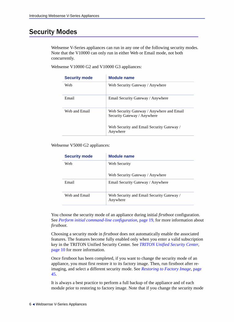
Websense V-Series appliances can run in any one of the following security modes. Note that the V10000 can only run in either Web or Email mode, not both concurrently.
Websense V10000 G2 and V10000 G3 appliances:
Websense V5000 G2 appliances:
You choose the security mode of an appliance during initial firstboot configuration. See Perform initial command-line configuration, page 19, for more information about firstboot.
Choosing a security mode in firstboot does not automatically enable the associated features. The features become fully enabled only when you enter a valid subscription key in the TRITON Unified Security Center. See TRITON Unified Security Center, page 10 for more information.
Once firstboot has been completed, if you want to change the security mode of an appliance, you must first restore it to its factory image. Then, run firstboot after re-imaging, and select a different security mode. See Restoring to Factory Image, page 45.
It is always a best practice to perform a full backup of the appliance and of each module prior to restoring to factory image. Note that if you change the security mode
Security mode Module name
Web Web Security Gateway / Anywhere
Email Email Security Gateway / Anywhere
Web and Email Web Security Gateway / Anywhere and Email Security Gateway / Anywhere
Web Security and Email Security Gateway / Anywhere
Security mode Module name
Web Web Security
Web Security Gateway / Anywhere
Email Email Security Gateway / Anywhere
Web and Email Web Security and Email Security Gateway / Anywhere
6 Websense V-Series Appliances

Introducing Websense V-Series Appliances
of an appliance after backing it up, the backup may or may not be applicable to the new mode. For example, you cannot restore from a backup file taken from Web Security (no proxy) to an appliance running Web Security Gateway (includes proxy).
Software provided on the appliance
Web components
On an appliance running in either Web mode or Web and Email mode, the following core Web security components are pre-loaded for your convenience:
Policy Database
Policy Broker
Policy Server
Filtering Service
User Service
Usage Monitor
Control Service
Directory Agent
State Server
Multiplexer
TRITON Unified Security Center (Web mode only), includes:
• TRITON Web Server• Unified Security Center• Settings Database• Investigative Reports Scheduler• Manager Web Server• Reporting Web Server• Reports Information Service
Network Agent
Web Security Gateway
If you configure Web Security Gateway during firstboot, then your appliance also includes:
Websense Content Gateway
On an appliance in Web mode (only), the TRITON console is installed on the appliance by default, and only its Web security functions are enabled. However, using the TRITON console on the appliance is optional and is typically only for convenience during evaluations. In production environments, it is best practice to run TRITON Unified Security Center off-appliance on a separate Windows machine. [Even for evaluations, TRITON Unified Security Center can run on the appliance only if the
Getting Started 7
Introducing Websense V-Series Appliances
appliance runs in full policy source mode.] See the Websense Appliance Manager Help for more information about the policy source.
If your organization generates a high volume of reports, or a lower volume of very large reports, hosting the TRITON console on the appliance can affect the performance of other appliance modules.
Email components
On an appliance running in Email mode or Web and Email mode, the appliance contains the majority of email security features, including the following services:
Configuration Service
Authentication Service
Quarantine Service
Log Service
Update Service
Filtering Service
Mail Transfer Agent
Only management (via the TRITON Unified Security Center), and logging (via Email Security Log Server) are performed by off-appliance components.
Software that runs off-appliance
The Websense components mentioned in this section must be installed off-appliance. Additionally, Microsoft SQL Server must be installed off-appliance.
Use the Websense Installer to install any of the components mentioned here. See the Websense Deployment and Installation Center for more information about components and installation instructions.
Web components
The following Web components never run on the appliance. Some are Windows-only components.
Important
If it is running on an appliance, the TRITON console has only its Web security functions enabled. If you want to use more than the Web security functions—for example, TRITON - Data Security—then TRITON Unified Security Center must be installed off-appliance on a Windows Server 2008 R2 machine.
8 Websense V-Series Appliances
Introducing Websense V-Series Appliances
Web Security Log Server
Real-Time Monitor
Remote Filtering Server
Sync Service (for sites using hybrid Web security)
Linking Service (for sites using any integrated Data Security features)
Transparent identification agents (to apply user, group, or domain [OU] policies without prompting users for credentials)
DC Agent
Logon Agent
eDirectory Agent
RADIUS Agent
Data Security components
The following Data Security components run off-appliance.
TRITON - Data Security console
Protector
Mobile Agent
SMTP agent
Microsoft ISA/TMG agent
Endpoint agent
Printer agent
The crawler
Integration agent
Email components
The following Email Security Gateway components never run on the appliance. They are Windows-only components.
TRITON - Email Security console (the Email Security module of the TRITON Unified Security Center; see TRITON Unified Security Center, page 10)
TRITON - Data Security console (the Data Security module of the TRITON Unified Security Center; see TRITON Unified Security Center, page 10). The Data Security module is required for email DLP (data leakage prevention) features.
Email Security Log Server
NoteIf your subscription includes Websense Web Security Gateway Anywhere, TRITON Unified Security Center must run off-appliance, on a Windows Server 2008 R2 machine.
Getting Started 9
Introducing Websense V-Series Appliances
TRITON Unified Security Center
The TRITON Unified Security Center (TRITON console) is the Web-browser-based, graphical management application for your entire deployment.
In addition to managing global settings and logging, it consists of three management modules: TRITON - Web Security, TRITON - Data Security, and TRITON - Email Security. Each module is used to configure and manage its respective product features.
Depending on your subscription, not all of these modules may be enabled.
To enable more than one module of the TRITON console—for example, both Web Security and Data Security—you must install the TRITON console on a Windows Server 2008 R2 machine. TRITON Unified Security Center must be able to reach the appliance’s C interface (and E1 interface, if the appliance is in Email mode or Web and Email mode).
Managing appliances in TRITON Unified Security Center
The TRITON Unified Security Center (TRITON console) provides a facility for managing Websense appliances in your network. Appliances that are part of your TRITON installation are registered automatically on the TRITON console at Appliances > Manage Appliances. Information for each appliance includes:
C interface IP address
Hostname
Security Mode (Web Security, Email Security, or both Web and Email Security)
If Web Security is enabled, Policy source (Full, Limited, or Filtering Only)
Software version (for example 7.7.0)
Hardware platform (for example V5000, V10000, V10000 G2, V10000 G3)
Appliance description
See the TRITON Unified Security Center online Help for complete details.
TRITON Infrastructure
TRITON Infrastructure is comprised of common user interface, logging, and reporting components required by the TRITON modules.
TRITON Infrastructure also (optionally) includes SQL Server 2008 R2 Express that may be used for Websense logging data. As a best practice, SQL Server 2008 R2 Express should be used only in non-production or evaluation environments. Full SQL Server should be used in production environments.
TRITON Infrastructure services include:
Websense TRITON Unified Security Center
Websense TRITON Central Access
Websense TRITON Settings Database
Websense TRITON Reporting Database (if using SQL Server 2008 R2 Express)
10 Websense V-Series Appliances
Introducing Websense V-Series Appliances
TRITON - Web Security
TRITON - Web Security is used to perform general configuration tasks, set up filtering policies, assign policies to users and groups, run reports, and other management tasks.
TRITON - Web Security services include:
Websense TRITON - Web Security (formerly ApacheTomcatWebsense)
Websense Web Reporting Tools (formerly Apache2Websense)
Investigative Reports Scheduler
Reports Information Service
Websense RTM Client (if Real-Time Monitor is used)
Websense RTM Database (if Real-Time Monitor is used)
Websense RTM Server (if Real-Time Monitor is used)
On an appliance in Web mode, TRITON Unified Security Center with the Web Security module only (TRITON - Web Security) is pre-installed as a convenience for evaluations and small installations. This component is not installed on an appliance that is in Web and Email mode.
Access the TRITON - Web Security console by entering the following address in a supported browser:
https://<IP address>:9443/mng
If you are using an off-box TRITON manager, replace <IP address> with the IP address of the server where you installed the TRITON manager.
If you are using the on-box TRITON manager, specify the IP address of interface C on the appliance.
Access to the TRITON - Web Security manager is secured with an SSL security certificate issued by Websense, Inc. Because the browser does not recognize Websense, Inc., as a known Certificate Authority (CA), a security warning is displayed.
NoteThe above service names are for an off-appliance installation of TRITON - Web Security. When on-appliance, Websense TRITON - Web Security has this service name: Manager Web Server, and Websense Web Reporting Tools have this service name: Reporting Web Server.
Getting Started 11
Introducing Websense V-Series Appliances
TRITON - Data Security
TRITON - Data Security consolidates all aspects of Websense Data Security setup andconfiguration, incident management, system status reports, and role-based administration.
TRITON - Data Security services include:
Websense Data Security Management Server
Websense TRITON - Data Security
Websense Data Policy Engine
Websense Data Fingerprint Database
Websense Data Discovery and Fingerprint Crawler
Websense PreciseID and Data Endpoint Server
TRITON - Email Security
TRITON - Email Security is used to configure and manage general system properties, administrator roles, user directories, email filtering, email policies, and Personal Email Manager end-user facility options. It is also used to generate and view email activity reports.
The off-appliance Websense Email Security management console consists of one service:
Websense TRITON - Email Security
Database management software
Websense Web security and Email security products require Microsoft SQL Server to host their respective reporting databases, both called the Log Database. Both the Web Security Log Database and the Email Security Log Database can be hosted by the same database engine instance. Information stored in these Log Databases is used to create reports.
Before you install Web Security Log Server or Email Security Log Server, SQL Server 2005 or 2008 must be installed and running on a machine in your network. See the Deployment and Installation Center for detailed information about supported versions of SQL Server. Note that SQL Server must be obtained separately; it is not included with your Websense subscription. Refer to Microsoft documentation for installation and configuration instructions.
If you do not have SQL Server, you can use the Websense Installer to install SQL Server 2008 R2 Express for evaluations. SQL Server 2008 R2 Express can be installed
12 Websense V-Series Appliances
Introducing Websense V-Series Appliances
either on the same machine as TRITON Unified Security Center or on a separate machine. See the Deployment and Installation Center for installation instructions.
V-Series 7.7.0 support for IPv6
Version 7.7 of TRITON Enterprise, including 7.7 V-Series appliances, provides incremental support for IPv6.
V-Series support is provided in combination with Web Security and Web Security Gateway (Anywhere).
IPv6 is not supported with Email Security Gateway.
For Web Security, IPv6 support includes:
Dual IP stack implementation on interfaces C and N
IPv6 traffic to the Internet or clients on interfaces C and N, including Block pages sent on C or N
IPv6 static routes
SNMP traps and counters for IPv6 data
Network diagnostic tools in the Command Line Utility and Command Line Interface
For Web Security Gateway (Anywhere), support includes all of the above, plus:
Dual IP stack implementation on interfaces P1 and P2
Traffic to the Internet or clients on interfaces P1 and P2, and their bonded interface (E1/E2), if configured
Limits and restrictions:
IPv6-only internal networks are not supported
IPv4 must be used to communicate among V-Series appliances and with TRITON components
NoteIt is a best practice to use full SQL Server in production environments. SQL Server 2008 R2 Express is most appropriate for non-production or evaluation environments.
ImportantTo use IPv6 with Web Security Gateway (Anywhere) the Content Gateway proxy must be configured as an explicit proxy. IPv6 is not supported in transparent proxy deployments.
Getting Started 13

Introducing Websense V-Series Appliances
See TRITON – Web Security Help and Content Gateway Manager Help for details.
IPv6 configuration summary
IPv6 support is disabled by default.
IPv6 is enabled in the Appliance Manager at the top of the Configuration > Network Interfaces > IPv6 page. When it is enabled, all IPv6 support is enabled for all affected capabilities on the appliance.
In any field that accepts an IPv6 address, the address can be entered in any format that conforms with the standard. For example:
Leading zeros within a 16-bit value may be omitted
One group of consecutive zeros may be replaced with a double colon
Disabling IPv6 support requires a full restart of the appliance.
When IPv6 is disabled, IPv6 values remain in the configuration files, but are not editable.
14 Websense V-Series Appliances

2
Setting Up Websense V-Series AppliancesSetting up a Websense V-Series appliance involves the following tasks.
1. Set up the appliance hardware, page 15
2. Perform initial command-line configuration, page 19
3. Configure the appliance, page 23
4. Install off-appliance or optional components, page 43
Additional initial configuration steps may be necessary for your particular deployment. See the Deployment and Installation Center for more information.
Set up the appliance hardware
The Quick Start poster, which is packaged in the appliance shipping box, shows you all items included in each Websense appliance shipment. The 2-page Quick Start poster explains how to set up the hardware and shows how to connect cables to the appliance and to your network.
Access V5000 G2 poster
Access V10000 G2 poster
Access V10000 G3 poster
Review the sections that apply to your Websense appliance model.
V10000, V10000 G2, and V10000 G3 hardware setup
V5000 G2 hardware setup
Serial port activation
V10000, V10000 G2, and V10000 G3 hardware setup
The appliance’s network interfaces must be able to access a DNS server and the Internet, as described below. This information varies slightly depending on the security mode you choose for the appliance.
V10000, V10000 G2, and V10000 G3 Web mode with Web Security Gateway
V10000 G2 and V10000 G3 Email mode
Getting Started 15

Setting Up Websense V-Series Appliances
V10000 G2 and V10000 G3: Web and Email mode with Web Security Gateway
V10000 G2 and V10000 G3: Web and Email mode with Web Security (no Web gateway)
V10000, V10000 G2, and V10000 G3 Web mode with Web Security Gateway
Network interface C must be able to access a DNS server. This interface typically has continuous access to the Internet. Essential databases are downloaded from Websense servers through interface C (or optionally through P1).
Ensure that interface C is able to access the download servers at download.websense.com. (As an alternative, some sites configure the P1 proxy interface to download the Websense Master Database as well as other security updates. This change must be made in the TRITON - Web Security console. In that situation, interface C does not require Internet access.)
Make sure the above address is permitted by all firewalls, proxy servers, routers, or host files controlling the URLs that the C interface can access.
V10000 G2 and V10000 G3 Email mode
Network interface E1 (and E2, if used) must be able to access a DNS server. These interfaces typically have continuous access to the Internet once the appliance is operational. Essential databases are downloaded from Websense servers through these interfaces.
Ensure that E1 (and E2, if used) are able to access the download servers at download.websense.com.
Make sure the above address is permitted by all firewalls, proxy servers, routers, or host files controlling the URLs that the E1 (and E2) interfaces can access.
Network interface E1 (and E2, if used) must be able to access the mail server.
V10000 G2 and V10000 G3: Web and Email mode with Web Security Gateway
Network interfaces C and E1 (and E2, if used) must be able to access a DNS server. These interfaces typically have continuous access to the Internet. Essential databases are downloaded from Websense servers through these interfaces.
Ensure that interfaces C and E1 (and E2, if used) are able to access the download servers at download.websense.com. (Note that some sites configure the P1 proxy interface (instead of the C interface) to download the Websense Master Database as well as other security updates. This change must be made in the TRITON - Web Security console. In that situation, interface C does not require Internet access.)
Make sure the above addresses are permitted by all firewalls, proxy servers, routers, or host files controlling the URLs that the C and E1 (and E2, if used) interfaces can access.
Network interface E1 (and E2, if used) must be able to access the mail server.
16 Websense V-Series Appliances

Setting Up Websense V-Series Appliances
V10000 G2 and V10000 G3: Web and Email mode with Web Security (no Web gateway)
Network interfaces C and E1 (and E2, if used) must be able to access a DNS server. These interfaces typically have continuous access to the Internet. Essential databases are downloaded from Websense servers through these interfaces.
Ensure that interfaces C and E1 (and E2, if used) are able to access the download servers at download.websense.com.
Make sure the above addresses are permitted by all firewalls, proxy servers, routers, or host files controlling the URLs that the C, E1, and E2 interfaces can access.
Network interfaces E1 and E2 (if used) must be able to access the mail server.
Network interface N must be connected to a mirror port on a router or switch.
If interface N is used to send blocking information, then it must be connected to a bi-directional mirror port. Through the bi-directional mirror port, interface N not only monitors all client traffic but also sends blocking information if needed.
V5000 G2 hardware setup
The appliance’s network interfaces must be able to access a DNS server and the Internet, as described below. This information varies slightly depending on the security mode you choose for the appliance.
V5000 G2: Web mode with Web Security Gateway
V5000 G2: Web mode with Web Security (no gateway)
V5000 G2: Web and Email mode with Web Security (no Web gateway)
V5000 G2: Email mode
V5000 G2: Web mode with Web Security Gateway
Network interface C must be able to access a DNS server. This interface typically has continuous access to the Internet. Essential databases are downloaded from Websense servers through interface C.
Ensure that interface C is able to access the download servers at download.websense.com. (As an alternative, some sites configure the P1 proxy interface to download the Websense Master Database as well as other security updates. This change must be made in the TRITON - Web Security console. In that situation, interface C does not require Internet access.)
Make sure the above addresses are permitted by all firewalls, proxy servers, routers, or host files controlling the URLs that the C interface can access.
V5000 G2: Web mode with Web Security (no gateway)
Network interface C must be able to access a DNS server. Interface C must have continuous access to the Internet. Essential databases are downloaded from Websense servers through this interface.
Getting Started 17

Setting Up Websense V-Series Appliances
Ensure that interface C is able to access the download servers at download.websense.com.
Make sure the above address is permitted by all firewalls, proxy servers, routers, or host files controlling the URLs that the C interface can access.
Network interface N must be connected to a mirror port on a router or switch.
If interface N is used to send blocking information, then it must be connected to a bi-directional mirror port. Through the bi-directional mirror port, interface N not only monitors all client traffic but also sends blocking information if needed.
V5000 G2: Web and Email mode with Web Security (no Web gateway)
Interfaces C and P1 (and P2, if used) must be able to access a DNS server. These interfaces typically have continuous access to the Internet once the appliance is operational. Essential databases are downloaded from Websense servers through these interfaces.
Ensure that C and P1 (and P2, if used) are able to access the download servers at download.websense.com.
Make sure the above addresses are permitted by all firewalls, proxy servers, routers, or host files controlling the URLs that the C, P1, and P2 interfaces can access.
Network interfaces P1 and P2 (if used) must be able to access the mail server.
V5000 G2: Email mode
Interface P1 (and P2, if used) must be able to access a DNS server. These interfaces typically have continuous access to the Internet once the appliance is operational. Essential databases are downloaded from Websense servers through these interfaces.
Ensure that P1 (and P2, if used) is able to access the download servers at download.websense.com.
Make sure the above addresess are permitted by all firewalls, proxy servers, routers, or host files controlling the URLs that the P1 and P2 interfaces can access.
Network interfaces P1 and P2 (if used) must be able to access the mail server.
Serial port activation
After hardware setup, connect directly to the appliance through the serial port or the monitor and keyboard ports. For serial port activation, use:
9600 baud rate
8 data bits
no parity
The activation script, called firstboot, runs when you start the appliance.
See Perform initial command-line configuration.
18 Websense V-Series Appliances
Setting Up Websense V-Series Appliances
After firstboot is run and the command-line shell is exited, accessing the appliance-command line shell requires the admin credentials (‘admin’ and the password you set during firstboot).
Perform initial command-line configuration
Setting up a Websense V-Series appliance involves the following tasks. This topic covers Step 2:
1. Set up the appliance hardware, page 15
2. Perform initial command-line configuration, page 19
Gather the data
Run firstboot
3. Configure the appliance, page 23
Network interface configuration
Routing configuration
Alerting
Configuring Web Security components
4. Install off-appliance or optional components, page 43
Additional initial configuration steps may be necessary for your particular deployment. See the Deployment and Installation Center for more information.
The first time you start a Websense appliance, a brief script (firstboot) prompts you:
select the security mode for the appliance
supply settings for the network interface labeled C
enter a few other general items, such as hostname and password
Getting Started 19

Setting Up Websense V-Series Appliances
You are given the opportunity to review and change these settings before you exit the firstboot script. After you approve the settings, the appliance mode is configured.
Later, if you want to change settings (except the security mode), you can do so through the Appliance Manager user interface.
To change the security mode, re-image the appliance with the image from the Websense Downloads site, and then run the firstboot script again.
Gather the data
Gather the following information before running the script. Some of this information may have been written down on the Quick Start poster during hardware setup.
Security mode Choose one:
Web
Web and Email
Which Web Security subscription?
(if prompted in Web mode)
Choose one:
Websense Web Security
Web Security Gateway
Web Security Gateway Anywhere
Hostname (example: appliance.domain.com)
1 - 60 characters long.
The first character must be a letter.
Allowed: letters, numbers, dashes, or periods.
The name cannot end with a period.
If this is a Web Security Gateway appliance and Content Gateway will be configured to perform Integrated Windows Authentication, the hostname cannot exceed 11 characters (excluding the domain name).
For more information, see the section titled Integrated Windows Authentication in Content Gateway Manager Help.
IP address for network interface C
Subnet mask for network interface C
20 Websense V-Series Appliances

Setting Up Websense V-Series Appliances
Default gateway for network interface C (IP address) Optional
NOTE: If you do not provide access to the Internet for interface C, use the TRITON - Web Security console to configure P1 to download Master URL Database updates from Websense (Web mode)
Configure E1 or P1* to download antispam and antivirus database updates from Websense (Email mode)
Configuring these interfaces to access the Internet for database downloads is done through the Appliance Manager and through the TRITON Unified Security Center. See the Appliance Manager Help for information about configuring the interfaces. See the TRITON - Web Security and - Email Security Help for information about configuring database downloads.
* On a V5000 G2, use P1; there is no E1 interface.
Primary DNS server for network interface C (IP address)
Secondary DNS server for network interface C (IP address) Optional
Tertiary DNS server for network interface C (IP address) Optional
Unified password (8 to 15 characters, at least 1 letter and 1 number)
This password is for the following, depending on the security mode of the appliance:
Web mode
Appliance Manager
TRITON - Web Security
Content Gateway Manager (for sites using Web Security Gateway / Anywhere)
Email mode
Appliance Manager
Web and Email mode
Appliance Manager
Content Gateway Manager (for sites using Web Security Gateway / Anywhere)
Getting Started 21
Setting Up Websense V-Series Appliances
Run firstboot
Run the initial command-line configuration script (firstboot) as follows.
1. Access the appliance through a USB keyboard and monitor, or a serial port connection.
2. Accept the subscription agreement when prompted.
3. When asked if you want to begin, enter yes to launch the firstboot activation script.
To rerun the script manually, enter the following command:
firstboot
4. At the first prompt, select a security mode:
Web: On models V10000 G2 and V10000 G3, this mode provides Web Security Gateway. On models V10000 and V5000 G2, Web mode provides either Web Security or Web Security Gateway, at your choice.
Email: provides Email Security Gateway features.
Web and Email: provides Email Security Gateway features and either Web Security Gateway (V10000 G2 or V10000 G3) or Web Security (V10000 G2, V10000 G3 or V5000 G2).
5. Follow the on-screen instructions to provide the information collected above.
Integration method for this appliance (for sites using Web Security. Choose one):
Standalone (Network Agent only)
Microsoft TMG
Cisco PIX
Cisco ASA
Citrix
Choose your third-party integration product (if any).
Send usage statistics? Usage statistics from appliance modules can optionally be sent to Websense to help improve the accuracy of filtering and categorization.
NoteTo configure the appliance, connect through the serial port or the keyboard/video ports and complete the firstboot script. For serial port activation, use:
9600 baud rate
8 data bits
no parity
22 Websense V-Series Appliances
Setting Up Websense V-Series Appliances
After the activation script has been completed successfully, access Appliance Manager by opening a supported browser and entering this URL in the address bar:
http://<IP-address-of-interface-C>:9447/appmng/
You are now ready to move to this step: Configure the appliance
Note that all Websense consoles support the following browsers:
Microsoft Internet Explorer 8 and 9
Mozilla Firefox versions 5 and later
Google Chrome 13 and later
Configure the appliance
Setting up a Websense V-Series appliance involves the following tasks. This topic covers Step 3:
1. Set up the appliance hardware
2. Perform initial command-line configuration
3. Configure the appliance
Network interface configuration
Routing configuration
Configuring Web Security components
4. Install off-appliance or optional components
Appliance Manager is a Web-based interface for the appliance. Use it to view system status, configure network and communication settings, and perform general appliance administration.
After completing the initial configuration required by the firstboot script, use the Appliance Manager to configure important settings for network interfaces P1, P2, N, E1, and E2 (some interfaces are optional in some modes). Note that on a V5000 G2, there are no E1 and E2 interfaces.
NoteIf you use Internet Explorer, ensure that Enhanced Security Configuration is switched off.
If you use Internet Explorer 8, note that Compatibility View is not supported.
Getting Started 23

Setting Up Websense V-Series Appliances
System Configuration
Access the Appliance Manager through a supported browser.
See the embedded Appliance Manager Help for detailed instructions on any field, or for information about other available settings.
1. Open a supported browser, and enter the following URL in the address bar:
https://<IP-address-of-C-interface>:9447/appmng
(See Perform initial command-line configuration.)
2. Log on with the user name admin and the password set during initial appliance configuration.
3. In the left navigation pane, click Configuration > System.
4. Under Time and Date:
Use the Time zone list to select the time zone to be used on this system.
GMT (Greenwich Mean Time), the default, is also known as UTC (Universal Time, Coordinated). Other time zones are calculated by adding or subtracting from GMT. GMT is sometimes chosen to provide a common time stamp for geographically distributed systems.
Use the Time and date radio buttons to indicate how you want to set the date.
Time is set and displayed using 24-hour notation.
• To synchronize with an Internet Network Time Protocol (NTP) server (www.ntp.org.), select the Automatically synchronize option and enter the address of a primary NTP server. The secondary and tertiary fields are optional.
Important
If any Websense services are running in your network, stop all Websense services before changing the time. Then, reset the time and make certain that the time is consistent across all servers running Websense services. Finally, restart Websense services.
If you do not stop the services first, client updates and policy changes entered after the time reset are not saved.
ImportantIf you synchronize the system clock with an NTP server, NTP protocol packets and their response packets must be allowed on any firewall or NAT device between the appliance and the NTP server. Ensure that you have outbound connectivity to the NTP servers. Add a firewall rule that allows outbound traffic to UDP port 123 for the NTP server.
24 Websense V-Series Appliances
Setting Up Websense V-Series Appliances
If interface C on this appliance is not connected to the Internet, then you must provide a way for interface C to reach an NTP server. One solution is to install an NTP server on the local network where interface C can reach it.
• To set the time yourself, select the Manually set option and change the value in the Date and Time fields. Use the format indicated below the entry field.
5. Create or edit a unique appliance description to help you identify and manage the system, particularly when there will be multiple appliances deployed.
The description is displayed in the appliance list in the TRITON Unified Security Center when the appliance is added there.
6. Click OK.
In each section that allows changes, OK saves and applies the new values. Cancel discards changes and restores entry field values to their current settings.
7. Proceed to Network interface configuration.
Getting Started 25
Setting Up Websense V-Series Appliances
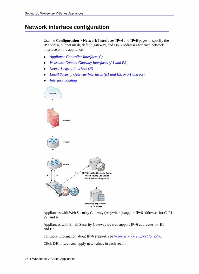
Network interface configuration
Use the Configuration > Network Interfaces IPv4 and IPv6 pages to specify the IP address, subnet mask, default gateway, and DNS addresses for each network interface on the appliance.
Appliance Controller Interface (C)
Websense Content Gateway Interfaces (P1 and P2)
Network Agent Interface (N)
Email Security Gateway Interfaces (E1 and E2, or P1 and P2)
Interface bonding
Appliances with Web Security Gateway (Anywhere) support IPv6 addresses for C, P1, P2, and N.
Appliances with Email Security Gateway do not support IPv6 addresses for E1 and E2.
For more information about IPv6 support, see V-Series 7.7.0 support for IPv6.
Click OK to save and apply new values in each section.
26 Websense V-Series Appliances
Setting Up Websense V-Series Appliances
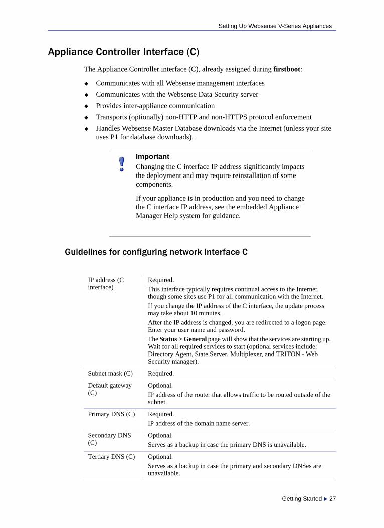
Appliance Controller Interface (C)
The Appliance Controller interface (C), already assigned during firstboot:
Communicates with all Websense management interfaces
Communicates with the Websense Data Security server
Provides inter-appliance communication
Transports (optionally) non-HTTP and non-HTTPS protocol enforcement
Handles Websense Master Database downloads via the Internet (unless your site uses P1 for database downloads).
Guidelines for configuring network interface C
ImportantChanging the C interface IP address significantly impacts the deployment and may require reinstallation of some components.
If your appliance is in production and you need to change the C interface IP address, see the embedded Appliance Manager Help system for guidance.
IP address (C interface)
Required.
This interface typically requires continual access to the Internet, though some sites use P1 for all communication with the Internet.
If you change the IP address of the C interface, the update process may take about 10 minutes.
After the IP address is changed, you are redirected to a logon page. Enter your user name and password.
The Status > General page will show that the services are starting up. Wait for all required services to start (optional services include: Directory Agent, State Server, Multiplexer, and TRITON - Web Security manager).
Subnet mask (C) Required.
Default gateway (C)
Optional.
IP address of the router that allows traffic to be routed outside of the subnet.
Primary DNS (C) Required.
IP address of the domain name server.
Secondary DNS (C)
Optional.
Serves as a backup in case the primary DNS is unavailable.
Tertiary DNS (C) Optional.
Serves as a backup in case the primary and secondary DNSes are unavailable.
Getting Started 27
Setting Up Websense V-Series Appliances
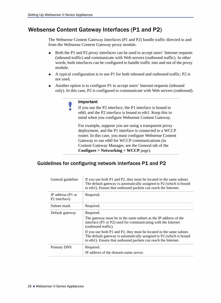
Websense Content Gateway Interfaces (P1 and P2)
The Websense Content Gateway Interfaces (P1 and P2) handle traffic directed to and from the Websense Content Gateway proxy module.
Both the P1 and P2 proxy interfaces can be used to accept users’ Internet requests (inbound traffic) and communicate with Web servers (outbound traffic). In other words, both interfaces can be configured to handle traffic into and out of the proxy module.
A typical configuration is to use P1 for both inbound and outbound traffic; P2 is not used.
Another option is to configure P1 to accept users’ Internet requests (inbound only). In this case, P2 is configured to communicate with Web servers (outbound).
Guidelines for configuring network interfaces P1 and P2
ImportantIf you use the P2 interface, the P1 interface is bound to eth0, and the P2 interface is bound to eth1. Keep this in mind when you configure Websense Content Gateway.
For example, suppose you are using a transparent proxy deployment, and the P1 interface is connected to a WCCP router. In this case, you must configure Websense Content Gateway to use eth0 for WCCP communications (in Content Gateway Manager, see the General tab of the Configure > Networking > WCCP page).
General guideline If you use both P1 and P2, they must be located in the same subnet. The default gateway is automatically assigned to P2 (which is bound to eth1). Ensure that outbound packets can reach the Internet.
IP address (P1 or P2 interface)
Required.
Subnet mask Required.
Default gateway Required.
The gateway must be in the same subnet as the IP address of the interface (P1 or P2) used for communicating with the Internet (outbound traffic).
If you use both P1 and P2, they must be located in the same subnet. The default gateway is automatically assigned to P2 (which is bound to eth1). Ensure that outbound packets can reach the Internet.
Primary DNS Required.
IP address of the domain name server.
28 Websense V-Series Appliances

Setting Up Websense V-Series Appliances
Network Agent Interface (N)
Network Agent is a software component used to filter protocols other than HTTP and HTTPS. It provides bandwidth optimization data and enhanced logging detail.
Network Agent continually monitors overall network usage, including bytes transferred over the network. The agent sends usage summaries to other Websense software at predefined intervals.
Network Agent is typically configured to see both inbound and outbound traffic in your network. The agent distinguishes between:
Requests sent from internal machines to internal machines (hits to an intranet server, for example)
Requests sent from internal machines to external machines such as Web servers (user Internet requests, for example)
You choose whether blocking information for non-HTTP protocols is routed through interface C or interface N.
Guidelines for configuring network interface N
Secondary DNS Optional.
Serves as a backup in case the primary DNS is unavailable.
Tertiary DNS Optional.
Serves as a backup in case the primary and secondary DNSes are unavailable.
Select an interface to use to send blocking information for non-HTTP and HTTPS traffic
Select Interface C only if you want to use interface C to send blocking information.
Select Interface N if network interface N is connected to a bidirectional span port, and you want to use N to transport blocking information.
Blocking NIC settings configured in TRITON - Web Security do not override the settings you enter in this pane. The settings in Appliance Manager take precedence.
IP address of interface N
Required.
Network Agent should be able to see the outbound and inbound traffic in your network. Network Agent ignores ports 80, 443, 8070, and 8080.
Subnet mask Required if interface N is selected. Otherwise the subnet mask has a fixed value of 255.255.255.255.
Default gateway Required if Interface N is checked. Otherwise, the field is disabled.
Primary DNS Required.
IP address of the domain name server.
Getting Started 29
Setting Up Websense V-Series Appliances
Network Agent can instead be installed on a different server in the network.
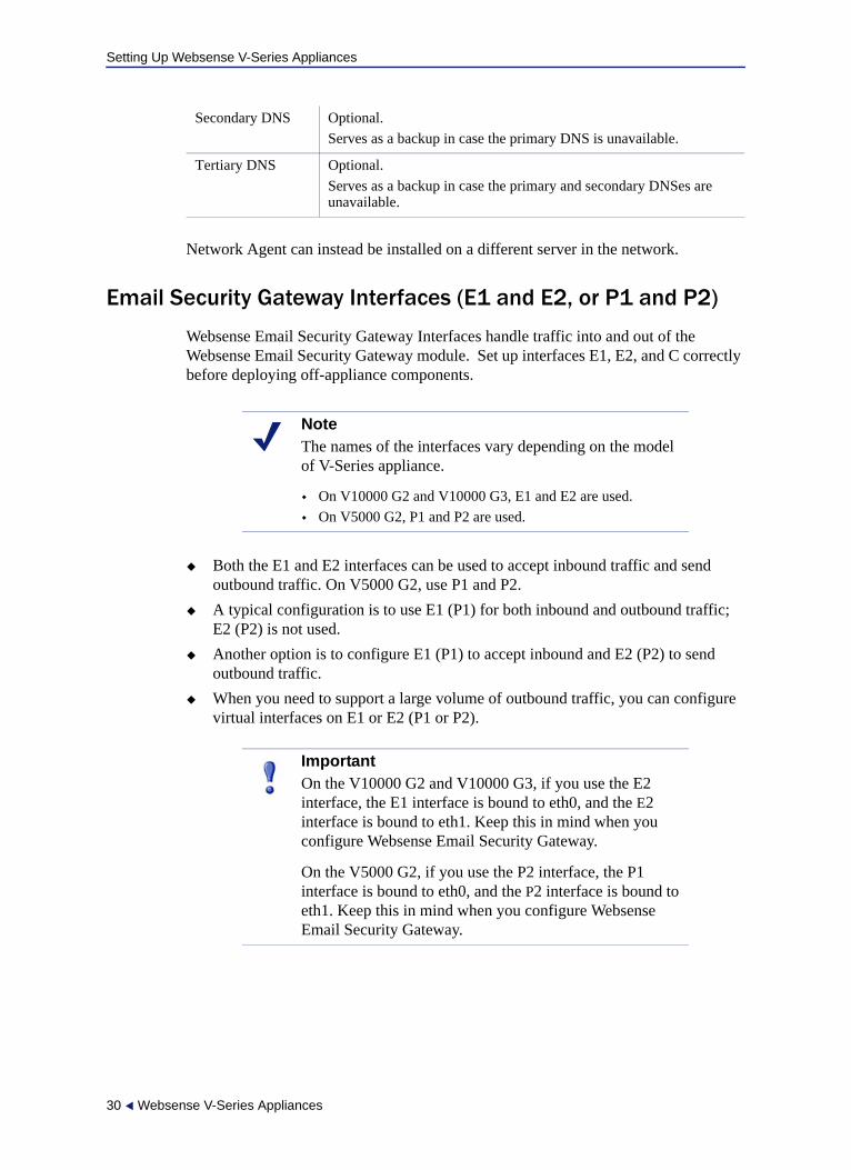
Email Security Gateway Interfaces (E1 and E2, or P1 and P2)
Websense Email Security Gateway Interfaces handle traffic into and out of the Websense Email Security Gateway module. Set up interfaces E1, E2, and C correctly before deploying off-appliance components.
Both the E1 and E2 interfaces can be used to accept inbound traffic and send outbound traffic. On V5000 G2, use P1 and P2.
A typical configuration is to use E1 (P1) for both inbound and outbound traffic; E2 (P2) is not used.
Another option is to configure E1 (P1) to accept inbound and E2 (P2) to send outbound traffic.
When you need to support a large volume of outbound traffic, you can configure virtual interfaces on E1 or E2 (P1 or P2).
Secondary DNS Optional.
Serves as a backup in case the primary DNS is unavailable.
Tertiary DNS Optional.
Serves as a backup in case the primary and secondary DNSes are unavailable.
NoteThe names of the interfaces vary depending on the model of V-Series appliance.
On V10000 G2 and V10000 G3, E1 and E2 are used.
On V5000 G2, P1 and P2 are used.
ImportantOn the V10000 G2 and V10000 G3, if you use the E2 interface, the E1 interface is bound to eth0, and the E2 interface is bound to eth1. Keep this in mind when you configure Websense Email Security Gateway.
On the V5000 G2, if you use the P2 interface, the P1 interface is bound to eth0, and the P2 interface is bound to eth1. Keep this in mind when you configure Websense Email Security Gateway.
30 Websense V-Series Appliances

Setting Up Websense V-Series Appliances
Guidelines for configuring network interfaces E1 and E2
If you use both E1 and E2, and you locate them in the same subnet, then the default gateway is automatically assigned to E2 (which is bound to eth1). Ensure that outbound packets can reach the Internet.
Email Security virtual interfaces
Multiple virtual IP addresses can be configured on E1 or E2.
Virtual IP addresses are used for outbound traffic only.
Virtual IP addresses are bound to the specified physical interface.
Virtual IP addresses must be in the same subnet as the specified physical interface.
A maximum of 10 virtual IP addresses can be specified for each physical interface (E1 and E2).
NoteOn a V5000 G2, substitute P1 for E1 and P2 for E2.
IP address (E1 or E2 interface)
Required.
E1 is used by default to connect to SQL Server for reporting. If E1 does not have a valid IP address or does not have DNS access, then Email Security Gateway cannot resolve the SQL Server hostname and cannot create a connection with SQL Server. Off-box installation of the management console is then blocked.
On a V5000 G2, substitute P1 for E1.
Subnet mask Required.
Default gateway Required.
The gateway must be in the same subnet as the IP address of the interface (E1 or E2) used for communicating with the Internet (outbound traffic).
If you use both E1 and E2, and you locate them in the same subnet, then the default gateway is automatically assigned to E2 (which is bound to eth1). Ensure that outbound packets can reach the Internet.
Primary DNS Required.
IP address of the domain name server.
Secondary DNS Optional.
Serves as a backup in case the primary DNS is unavailable.
Tertiary DNS Optional.
Serves as a backup in case the primary and secondary DNSes are unavailable.
Getting Started 31

Setting Up Websense V-Series Appliances
Multiple virtual interfaces can be helpful to support multiple domains or a large volume of outbound traffic.
To add virtual IP addresses to E1 or E2:
1. Go to Configure > Network Interfaces > Virtual Interfaces and click Add.
2. Select E1 or E2. If E2 has not been configured, it is not offered.
3. In the Virtual IP address entry field enter one IPv4 address per line.
4. Click Add Interfaces.
If you are not configuring interface bonding at this time, proceed next to Routing configuration.
Interface bonding
V10000 appliances (Websense Web Security only) and V10000 G2 or V10000 G3 appliances that run one module only—Websense Web Security or Websense Email Security Gateway—can bond interfaces for failover or load balancing. Configuration details are provided below.
Interface bonding is not supported on V5000 G2 appliances.
IMPORTANT: Do not bond interfaces that have different speeds or duplex modes. Doing so can result in performance problems.
V10000/V10000 G2/V10000 G3 with Websense Web Security only
Interfaces E1 and E2 can be cabled to your network and then bonded through software settings to a Websense Content Gateway interface, with E1 optionally bonded to P1, and E2 optionally bonded to P2. No other pairing is possible.
Interface bonding provides these alternatives:
Active/Standby mode: P1 (or P2) is active, and E1 (or E2) is in standby mode. Only if the primary interface fails would its bonded interface (E1 or E2) become active.
Load balancing: If the switch or router that is directly connected to the V10000/V10000 G2/V10000 G3 supports load balancing (etherchannel, trunk group, or similar), then traffic to and from the primary interface can be balanced between the primary interface and its bonded interface (E1 or E2).
You can choose to bond or not bond each Websense Content Gateway interface (P1 and P2) independently. You do not have to bond at all.
If you do bond an interface (P1 or P2), choose one mode for that bonding (either active/standby or load balancing). You do not have to choose the same bonding mode for both.
Ensure that all interfaces are cabled properly before bonding. Do not bond interfaces that have different speeds or duplex modes. Doing so can result in performance problems.
32 Websense V-Series Appliances
Setting Up Websense V-Series Appliances
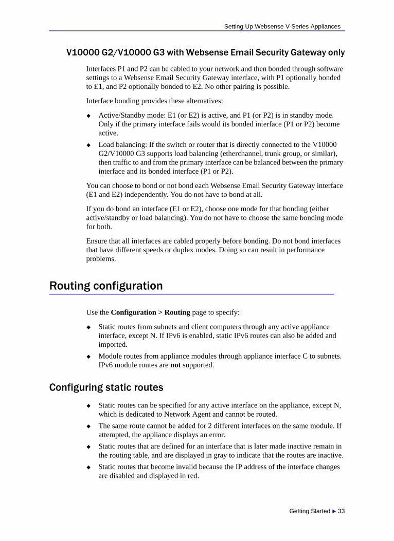
V10000 G2/V10000 G3 with Websense Email Security Gateway only
Interfaces P1 and P2 can be cabled to your network and then bonded through software settings to a Websense Email Security Gateway interface, with P1 optionally bonded to E1, and P2 optionally bonded to E2. No other pairing is possible.
Interface bonding provides these alternatives:
Active/Standby mode: E1 (or E2) is active, and P1 (or P2) is in standby mode. Only if the primary interface fails would its bonded interface (P1 or P2) become active.
Load balancing: If the switch or router that is directly connected to the V10000 G2/V10000 G3 supports load balancing (etherchannel, trunk group, or similar), then traffic to and from the primary interface can be balanced between the primary interface and its bonded interface (P1 or P2).
You can choose to bond or not bond each Websense Email Security Gateway interface (E1 and E2) independently. You do not have to bond at all.
If you do bond an interface (E1 or E2), choose one mode for that bonding (either active/standby or load balancing). You do not have to choose the same bonding mode for both.
Ensure that all interfaces are cabled properly before bonding. Do not bond interfaces that have different speeds or duplex modes. Doing so can result in performance problems.
Routing configuration
Use the Configuration > Routing page to specify:
Static routes from subnets and client computers through any active appliance interface, except N. If IPv6 is enabled, static IPv6 routes can also be added and imported.
Module routes from appliance modules through appliance interface C to subnets. IPv6 module routes are not supported.
Configuring static routes
Static routes can be specified for any active interface on the appliance, except N, which is dedicated to Network Agent and cannot be routed.
The same route cannot be added for 2 different interfaces on the same module. If attempted, the appliance displays an error.
Static routes that are defined for an interface that is later made inactive remain in the routing table, and are displayed in gray to indicate that the routes are inactive.
Static routes that become invalid because the IP address of the interface changes are disabled and displayed in red.
Getting Started 33
Setting Up Websense V-Series Appliances
Static routes can be added and deleted, but not modified. To modify a route, delete it and add a new route specifying the new values.
When a static route is added, imported, or deleted, the services associated with the module that manage the specified interface must be restarted. For example, if static routes are added to interface P1, when the additions are complete, all Content Gateway services must be restarted.
The static route table has a maximum limit of 5000 entries.
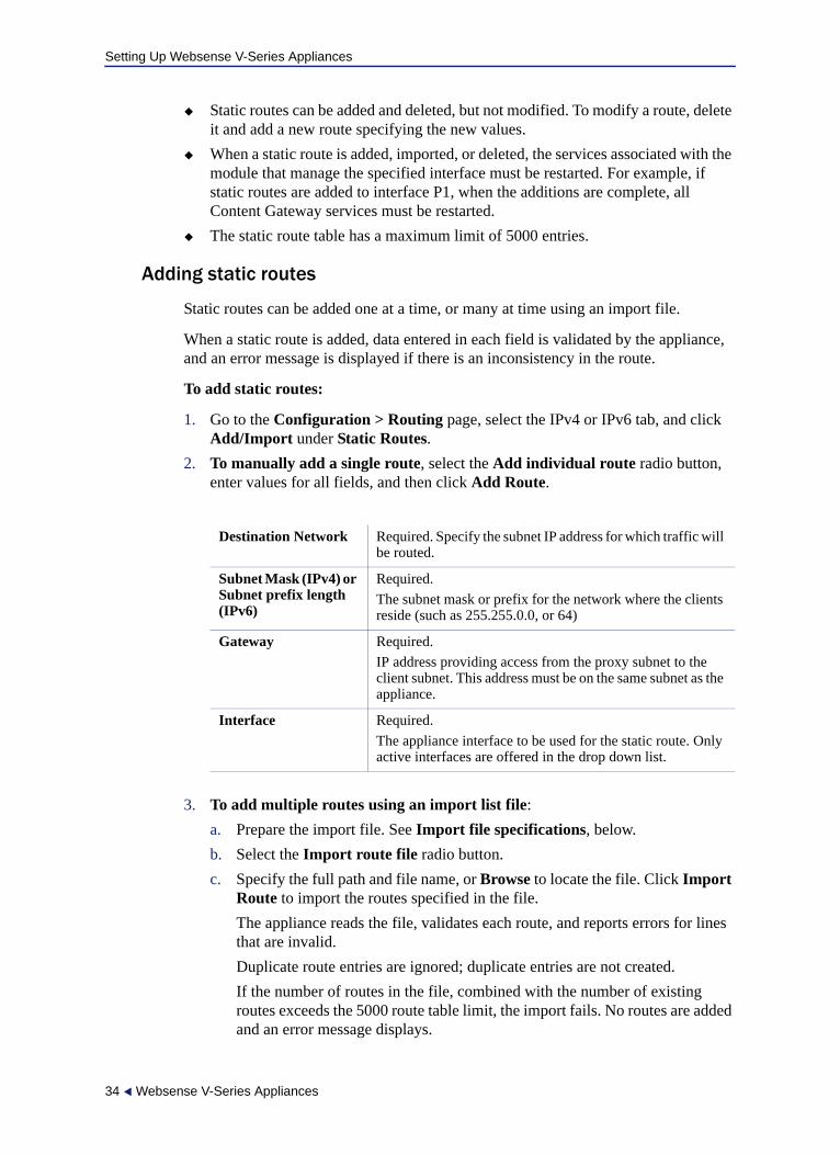
Adding static routes
Static routes can be added one at a time, or many at time using an import file.
When a static route is added, data entered in each field is validated by the appliance, and an error message is displayed if there is an inconsistency in the route.
To add static routes:
1. Go to the Configuration > Routing page, select the IPv4 or IPv6 tab, and click Add/Import under Static Routes.
2. To manually add a single route, select the Add individual route radio button, enter values for all fields, and then click Add Route.
3. To add multiple routes using an import list file:
a. Prepare the import file. See Import file specifications, below.
b. Select the Import route file radio button.
c. Specify the full path and file name, or Browse to locate the file. Click Import Route to import the routes specified in the file.
The appliance reads the file, validates each route, and reports errors for lines that are invalid.
Duplicate route entries are ignored; duplicate entries are not created.
If the number of routes in the file, combined with the number of existing routes exceeds the 5000 route table limit, the import fails. No routes are added and an error message displays.
Destination Network Required. Specify the subnet IP address for which traffic will be routed.
Subnet Mask (IPv4) or Subnet prefix length (IPv6)
Required.
The subnet mask or prefix for the network where the clients reside (such as 255.255.0.0, or 64)
Gateway Required.
IP address providing access from the proxy subnet to the client subnet. This address must be on the same subnet as the appliance.
Interface Required.
The appliance interface to be used for the static route. Only active interfaces are offered in the drop down list.
34 Websense V-Series Appliances
Setting Up Websense V-Series Appliances
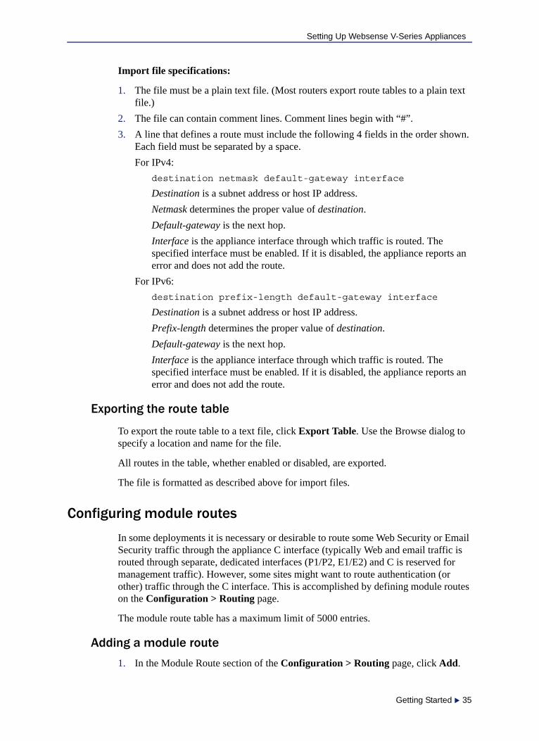
Import file specifications:
1. The file must be a plain text file. (Most routers export route tables to a plain text file.)
2. The file can contain comment lines. Comment lines begin with “#”.
3. A line that defines a route must include the following 4 fields in the order shown. Each field must be separated by a space.
For IPv4:
destination netmask default-gateway interface
Destination is a subnet address or host IP address.
Netmask determines the proper value of destination.
Default-gateway is the next hop.
Interface is the appliance interface through which traffic is routed. The specified interface must be enabled. If it is disabled, the appliance reports an error and does not add the route.
For IPv6:
destination prefix-length default-gateway interface
Destination is a subnet address or host IP address.
Prefix-length determines the proper value of destination.
Default-gateway is the next hop.
Interface is the appliance interface through which traffic is routed. The specified interface must be enabled. If it is disabled, the appliance reports an error and does not add the route.
Exporting the route table
To export the route table to a text file, click Export Table. Use the Browse dialog to specify a location and name for the file.
All routes in the table, whether enabled or disabled, are exported.
The file is formatted as described above for import files.
Configuring module routes
In some deployments it is necessary or desirable to route some Web Security or Email Security traffic through the appliance C interface (typically Web and email traffic is routed through separate, dedicated interfaces (P1/P2, E1/E2) and C is reserved for management traffic). However, some sites might want to route authentication (or other) traffic through the C interface. This is accomplished by defining module routes on the Configuration > Routing page.
The module route table has a maximum limit of 5000 entries.
Adding a module route
1. In the Module Route section of the Configuration > Routing page, click Add.
Getting Started 35
Setting Up Websense V-Series Appliances
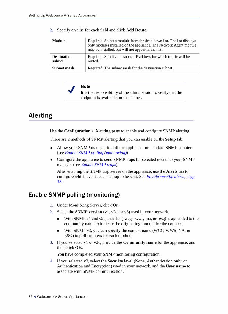
2. Specify a value for each field and click Add Route.
Alerting
Use the Configuration > Alerting page to enable and configure SNMP alerting.
There are 2 methods of SNMP alerting that you can enable on the Setup tab:
Allow your SNMP manager to poll the appliance for standard SNMP counters (see Enable SNMP polling (monitoring)).
Configure the appliance to send SNMP traps for selected events to your SNMP manager (see Enable SNMP traps).
After enabling the SNMP trap server on the appliance, use the Alerts tab to configure which events cause a trap to be sent. See Enable specific alerts, page 38.
Enable SNMP polling (monitoring)
1. Under Monitoring Server, click On.
2. Select the SNMP version (v1, v2c, or v3) used in your network.
With SNMP v1 and v2c, a suffix (-wcg, -wws, -na, or -esg) is appended to the community name to indicate the originating module for the counter.
With SNMP v3, you can specify the context name (WCG, WWS, NA, or ESG) to poll counters for each module.
3. If you selected v1 or v2c, provide the Community name for the appliance, and then click OK.
You have completed your SNMP monitoring configuration.
4. If you selected v3, select the Security level (None, Authentication only, or Authentication and Encryption) used in your network, and the User name to associate with SNMP communication.
Module Required. Select a module from the drop down list. The list displays only modules installed on the appliance. The Network Agent module may be installed, but will not appear in the list.
Destination subnet
Required. Specify the subnet IP address for which traffic will be routed.
Subnet mask Required. The subnet mask for the destination subnet.
NoteIt is the responsibility of the administrator to verify that the endpoint is available on the subnet.
36 Websense V-Series Appliances
Setting Up Websense V-Series Appliances
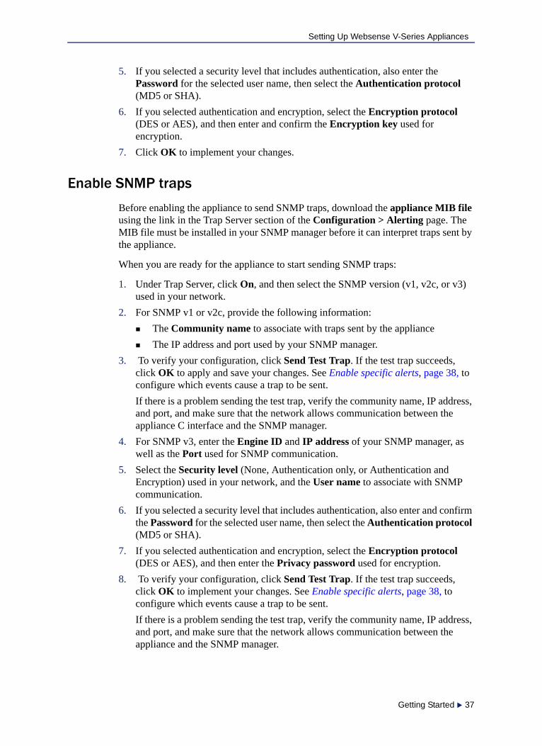
5. If you selected a security level that includes authentication, also enter the Password for the selected user name, then select the Authentication protocol (MD5 or SHA).
6. If you selected authentication and encryption, select the Encryption protocol (DES or AES), and then enter and confirm the Encryption key used for encryption.
7. Click OK to implement your changes.
Enable SNMP traps
Before enabling the appliance to send SNMP traps, download the appliance MIB file using the link in the Trap Server section of the Configuration > Alerting page. The MIB file must be installed in your SNMP manager before it can interpret traps sent by the appliance.
When you are ready for the appliance to start sending SNMP traps:
1. Under Trap Server, click On, and then select the SNMP version (v1, v2c, or v3) used in your network.
2. For SNMP v1 or v2c, provide the following information:
The Community name to associate with traps sent by the appliance
The IP address and port used by your SNMP manager.
3. To verify your configuration, click Send Test Trap. If the test trap succeeds, click OK to apply and save your changes. See Enable specific alerts, page 38, to configure which events cause a trap to be sent.
If there is a problem sending the test trap, verify the community name, IP address, and port, and make sure that the network allows communication between the appliance C interface and the SNMP manager.
4. For SNMP v3, enter the Engine ID and IP address of your SNMP manager, as well as the Port used for SNMP communication.
5. Select the Security level (None, Authentication only, or Authentication and Encryption) used in your network, and the User name to associate with SNMP communication.
6. If you selected a security level that includes authentication, also enter and confirm the Password for the selected user name, then select the Authentication protocol (MD5 or SHA).
7. If you selected authentication and encryption, select the Encryption protocol (DES or AES), and then enter the Privacy password used for encryption.
8. To verify your configuration, click Send Test Trap. If the test trap succeeds, click OK to implement your changes. See Enable specific alerts, page 38, to configure which events cause a trap to be sent.
If there is a problem sending the test trap, verify the community name, IP address, and port, and make sure that the network allows communication between the appliance and the SNMP manager.
Getting Started 37

Setting Up Websense V-Series Appliances
Enable specific alerts
The appliance can send traps for each of its modules: Appliance Controller, Websense Content Gateway, Websense Web Security, Network Agent, and Email Security Gateway. The Alerts tab of the Configuration > Alerting page lists the alerts associated with only the modules that you have enabled.
A table for each module lists:
The hardware or software Event that triggers the alert (for example, a network interface link going down or coming up, or a Websense service stopping).
The Threshold, if applicable, that defines the alert condition (for example, CPU usage exceeding 90%, or free disk space reaching less than 10% of the total disk size).
The Type of alert (system resource or operational event).
Whether or not an SNMP trap is sent when the event occurs or the threshold is reached.
To enable all alerts for a module, select the check box next to SNMP in the table header. All check boxes in the column are selected.
Otherwise, mark the check box next to an event name to enable SNMP alerts for that event. To disable alerts for an event, clear the associated check box.
Time-based thresholds: Most of the events that have a configurable threshold also have a configurable time-based threshold, specified in minutes. When the time-based threshold is set and both thresholds are exceeded, an alert is sent. To enabled time-based thresholds, select the Enable time-based thresholds check box at the top of the page. The time-based threshold is enabled on every event for which it is configurable.
Event-cleared alerts: In addition to generating event condition alerts, you can configure alerts to be sent when conditions return below the threshold. These are called event-cleared alerts. To enable event-cleared alerts, select the Generate event-cleared alerts check box at the top of the page.
The following events do not generate event-cleared alerts:
Hostname change
IP address change
Scheduled backup failure
SNMP authentication failure
When you have finished configuring alerts, click OK to implement the changes.
Proceed next to Configuring Web Security components.
38 Websense V-Series Appliances

Setting Up Websense V-Series Appliances
Configuring Web Security components
Use the Configuration > Web Security Components page to specify which Web Security components are active on the appliance, and where the appliance gets Web Security global configuration and filtering policy information. Also define the TRITON - Web Security location.
Under Policy Source, select which Web Security configuration is used on this appliance: Full policy source (default; see What is a policy source?), User directory and filtering, or Filtering only (see What if an appliance is not the policy source?).If this is a Full policy source appliance, it acts as both the Policy Broker and a Policy Server. There can be only 1 Full policy source appliance in your network.
If this is a User directory and filtering appliance, it also acts as a Policy Server. Enter the IP address of the Policy Broker appliance or server.
If this is a Filtering only appliance, enter the IP address of a Policy Server. It does not have to be the IP address of the Policy Broker machine.
1. Click OK to save and apply your changes.
2. If this is a Web Security only (or Web Security Gateway only) appliance running as a Full policy source, under TRITON - Web Security, specify whether to use the TRITON instance installed On the appliance, or whether to use an Off-appliance instance.
If you are using Websense Data Security or Email Security Gateway in conjunction with Websense Web Security Gateway, the TRITON Unified Security Center must be installed on an Windows Server 2008 R2 64-bit machine.
Generally, the on-appliance installation of TRITON - Web Security is intended for evaluations and small deployments. Most production sites are advised to download the TRITON installer from mywebsense.com and install the TRITON console on a separate Windows server.
3. If you are moving from using an off-appliance TRITON - Web Security instance to using the on-appliance instance, make sure you have backed up your original TRITON console. Then expand Import Configuration and browse to the location of your backup file.
This allows you to move much of your existing configuration and policy information to the appliance, rather than having to recreate your settings.
NoteWhen you upgrade from an earlier version of the appliance, your previous settings are preserved. If you do not have an off-appliance management console location already established, the system uses TRITON - Web Security on the policy source appliance by default.
Getting Started 39
Setting Up Websense V-Series Appliances
As always, be sure to verify the configuration in the new TRITON console, as some settings may not be preserved during migration.
4. Click OK to save and apply your changes.
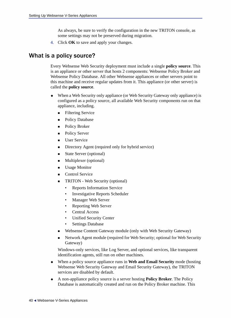
What is a policy source?
Every Websense Web Security deployment must include a single policy source. This is an appliance or other server that hosts 2 components: Websense Policy Broker and Websense Policy Database. All other Websense appliances or other servers point to this machine and receive regular updates from it. This appliance (or other server) is called the policy source.
When a Web Security only appliance (or Web Security Gateway only appliance) is configured as a policy source, all available Web Security components run on that appliance, including.
Filtering Service
Policy Database
Policy Broker
Policy Server
User Service
Directory Agent (required only for hybrid service)
State Server (optional)
Multiplexer (optional)
Usage Monitor
Control Service
TRITON - Web Security (optional)
• Reports Information Service• Investigative Reports Scheduler• Manager Web Server• Reporting Web Server• Central Access• Unified Security Center• Settings Database
Websense Content Gateway module (only with Web Security Gateway)
Network Agent module (required for Web Security; optional for Web Security Gateway)
Windows-only services, like Log Server, and optional services, like transparent identification agents, still run on other machines.
When a policy source appliance runs in Web and Email Security mode (hosting Websense Web Security Gateway and Email Security Gateway), the TRITON services are disabled by default.
A non-appliance policy source is a server hosting Policy Broker. The Policy Database is automatically created and run on the Policy Broker machine. This
40 Websense V-Series Appliances
Setting Up Websense V-Series Appliances
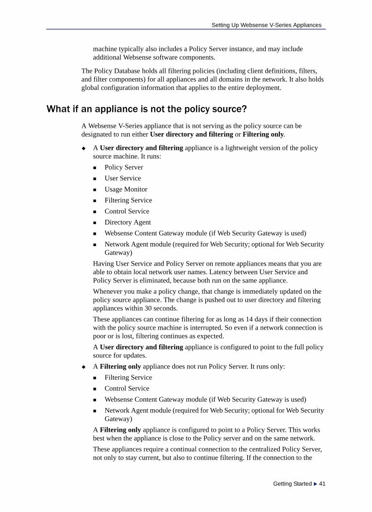
machine typically also includes a Policy Server instance, and may include additional Websense software components.
The Policy Database holds all filtering policies (including client definitions, filters, and filter components) for all appliances and all domains in the network. It also holds global configuration information that applies to the entire deployment.
What if an appliance is not the policy source?
A Websense V-Series appliance that is not serving as the policy source can be designated to run either User directory and filtering or Filtering only.
A User directory and filtering appliance is a lightweight version of the policy source machine. It runs:
Policy Server
User Service
Usage Monitor
Filtering Service
Control Service
Directory Agent
Websense Content Gateway module (if Web Security Gateway is used)
Network Agent module (required for Web Security; optional for Web Security Gateway)
Having User Service and Policy Server on remote appliances means that you are able to obtain local network user names. Latency between User Service and Policy Server is eliminated, because both run on the same appliance.
Whenever you make a policy change, that change is immediately updated on the policy source appliance. The change is pushed out to user directory and filtering appliances within 30 seconds.
These appliances can continue filtering for as long as 14 days if their connection with the policy source machine is interrupted. So even if a network connection is poor or is lost, filtering continues as expected.
A User directory and filtering appliance is configured to point to the full policy source for updates.
A Filtering only appliance does not run Policy Server. It runs only:
Filtering Service
Control Service
Websense Content Gateway module (if Web Security Gateway is used)
Network Agent module (required for Web Security; optional for Web Security Gateway)
A Filtering only appliance is configured to point to a Policy Server. This works best when the appliance is close to the Policy server and on the same network.
These appliances require a continual connection to the centralized Policy Server, not only to stay current, but also to continue filtering. If the connection to the
Getting Started 41
Setting Up Websense V-Series Appliances
Policy Server becomes unavailable for any reason, filtering on a Filtering only appliance can continue for up to 3 hours.
If the Policy Server machine is on a remote network, with a WAN connection, it can be difficult to obtain user name/IP address maps for the local users.
User directory with V-Series appliances
If your organization relies on user identification or authentication, each appliance that is running Websense User Service must be configured to talk to a user directory. Multiple appliances can talk to the same user directory, or to different user directories.
Preparing for a hybrid configuration
In Web Security Gateway Anywhere environments, some users may be filtered by the hybrid (SaaS) service. In this situation, an interoperability component on the appliance called Directory Agent is required to enable user-, group-, and domain- (OU) based filtering.
Directory Agent must be able to communicate with:
A supported LDAP-based directory service:
Windows Active Directory® (Mixed Mode)
Windows Active Directory (Native Mode®)
Oracle (Sun Java™) System Directory
Novell eDirectory
Websense Sync Service
After deployment, use TRITON - Web Security to configure User Service and Directory Agent.
User Service configuration is performed on the Settings > General > Directory Services page.
Directory Agent configuration is performed on the Settings > Hybrid Configuration > Shared User Data page.
You can have multiple Directory Agent instances.
Each Directory Agent must use a unique, non-overlapping root context.
Each Directory Agent instance must be associated with a different Policy Server.
All Directory Agent instances must connect to a single Sync Service. (A deployment can have only one Sync Service instance.)
You must configure the Sync Service connection manually for all supplemental Directory Agent instances (these are the Directory Agents running on User Directory and filtering, and Filtering only appliances). Communication is configured automatically for the Directory Agent instance that connects to the same Policy Server as Sync Service. See the TRITON - Web Security Help for details.
42 Websense V-Series Appliances

Setting Up Websense V-Series Appliances
You can configure Directory Agent to use a different root context than User Service, and to process its directory data differently than User Service. Also, with Windows Active Directory, if User Service is configured to communicate with multiple global catalog servers, Directory Agent can communicate with all of them.
Redundancy
Internet usage filtering requires interaction between several Websense software components:
User requests for Internet access are proxied by Content Gateway.
User requests for Internet access may also be monitored by Network Agent.
The requests are sent to Websense Filtering Service for processing.
Filtering Service communicates with Policy Server and Policy Broker to apply the appropriate policy in response to the request.
In some networks, additional machines may be used to deploy additional instances of Content Gateway, Filtering Service, Network Agent, or other components. For example, in a large, segmented network, you may need a separate Network Agent for each segment. Or, you might deploy the Remote Filtering Server on a separate computer, to enable filtering of laptops and other computers that are outside the organization’s network.
Check the Websense Deployment and Installation Center for component distribution options. Contact your Websense Sales Engineer, or your authorized Websense reseller, for assistance in planning a more complex deployment.
Install off-appliance or optional components
Setting up a Websense V-Series appliance involves the following tasks. This topic covers Step 4:
1. Set up the appliance hardware
2. Perform initial command-line configuration
3. Configure the appliance
Network interface configuration
Routing configuration
Alerting
Configuring Web Security components
4. Install off-appliance or optional components
After the appliance has been configured, install the off-appliance components you want.
Getting Started 43
Setting Up Websense V-Series Appliances
NOTE: Before deploying off-appliance components, be sure to use Appliance Manager to configure the appliance interfaces that you plan to use [C, P1, P2 (optional), E1, and E2 (optional)]. At sites using Email Security Gateway, E1 is used by default to connect to SQL Server for reporting. If E1 does not have a valid IP address or does not have DNS access, then Email Security Gateway cannot resolve the SQL Server hostname and cannot create a connection with SQL Server. In that situation, off-box installation of the management console is blocked. [On a V5000 G2, substitute P1 for E1.]
See Software that runs off-appliance, page 8, for more information about these components. Run the Websense Installer (in custom installation mode) on the machine to which you want to install components. See the Websense Technical Library for instructions.
Additional instances of Web security filtering components may be installed on machines in your network to provide additional functions or distribute processing load. For example, you can install additional Websense Network Agent instances on machines in your network.
Creating a TRITON management server
The machine on which TRITON Unified Security Center is installed is referred to as the TRITON management server. See the Websense Technical Library for instructions on creating a TRITON management server.
Access the TRITON - Web Security console by entering the following address in a supported browser:
https://<IP address>:9443/mng
NoteIf Policy Broker runs on an appliance, only on-appliance instances of Policy Server can communicate with Policy Broker. In this case, Policy Server cannot be installed off-appliance. If Policy Broker is installed off-appliance, however, both on-appliance and off-appliance instances of Policy Server can communicate with it.
ImportantThe appliance must be set up and configured before you create a TRITON management server. If you have not done so already, complete the following procedures before creating a TRITON management server:
Set up the appliance hardware, page 15
Perform initial command-line configuration, page 19
Configure the appliance, page 23
44 Websense V-Series Appliances
Setting Up Websense V-Series Appliances
If you are using an off-box TRITON manager, replace <IP address> with the IP address of the server where you installed the TRITON manager.
If you are using the on-box TRITON manager, specify the IP address of interface C on the appliance.
Access to the TRITON - Web Security manager is secured with an SSL security certificate issued by Websense, Inc. Because the browser does not recognize Websense, Inc., as a known Certificate Authority (CA), a security warning is displayed.
Restoring to Factory Image
The V10000, V10000 G2, and V5000 G2 come with a recovery DVD that can be used to restore the appliance to its factory image. You can use this DVD (after saving a Full configuration backup) to re-image the appliance and then recover your custom appliance and module settings. The V10000 G3 appliance ships with a later version of Websense software. You must download the 7.7.0 image for the appliance from MyWebsense. See the Installing 7.6.x or 7.7.0 on a V10000 G3 Appliance instructions for more information.
Note that all Websense components running off the appliance must be stopped before you reset to factory image.
1. Stop all Websense components that are running off the appliance. For example, stop Web Security or Email Security Log Servers, Sync Service, Linking Service, transparent ID agents, and TRITON Unified Security Center.
2. If possible, back up any information you want preserved.
a. Using a Web browser, log onto the Appliance Manager:
https://<C interface IP address>:9447/appmng/
b. Go to Administration > Backup Utility, and create a Full Configuration backup. See online Help for assistance. Save this backup file to another machine.
3. Go to the machine rack and insert the recovery disk into the appliance DVD drive.
4. Reboot the appliance. (An alternative is to turn off the power, and then turn it on again.)
ImportantFor all appliance except the V10000 G3, use the original recovery DVD that came with your appliance. If you have misplaced it, you can download a DVD image from MyWebsense. It is important you use an image that is associated with the manufacture date of your appliance. The MyWebsense Downloads page will indicate the appliance manufacture date appropriate for each image.
Getting Started 45
Setting Up Websense V-Series Appliances
5. Watch the terminal screen closely after the reboot starts. When a list of function keys appears at the upper right during reboot, press F11. Then select one of the following:
Boot from SATA Optical drive (V10000 and V10000 G2)
Boot from Embedded SATA 1 TEAC DVD-ROM DV-28SW drive (V5000 G2)
Boot from Primary CDROM: TEAC DVD-ROM DV-28SW drive (V5000 G2R2)
6. When asked whether you want to continue, enter yes.
Restoring the image can take 20 minutes or more. When the DVD is ejected, be sure to remove it from the drive.
7. Press any key to view the subscription agreement.
8. Enter yes to accept the subscription agreement, and then enter yes to begin firstboot.
This begins the firstboot script.
9. Follow the on-screen instructions at the terminal and provide the necessary information.
See Perform initial command-line configuration for details about what information is requested.
Restore backed-up configuration
1. Restore the backed up configuration via the Appliance Manager.
a. Using a Web browser, log onto the Appliance Manager
https://<C interface IP address>:9447/appmng
b. Go to Administration > Backup Utility.
c. Choose Restore.
2. Select Full Appliance Configuration restore mode and click Run Restore Wizard.
3. In the Restore Wizard:
a. File Location: Select Another location (browse for file). Then click Next.
b. Select File: Browse to the backup file (*.bak file) to select it. Then click Next.
c. Confirm: Verify backup file details and then click Restore Now.
The appliance will be rebooted automatically after the restore is complete. Appliance and software module settings are restored.
4. Ensure that the appliance time and date are synchronized with other servers.
5. Restart the components that run off the appliance.
6. On occasion, a manual download of the Websense Web Security Master Database should be initiated after a recovery. Do this in the TRITON Unified Security Center (Web Security module) if you receive a warning message about the Master Database.
46 Websense V-Series Appliances