shmc getting started - samway - products getting started... · shmc getting started rev 1.0 shmc...
TRANSCRIPT

ShMC Getting Started Rev 1.0
ShMC Getting Started
Revision History: Rev 1.0 01.10.2013 First Draft
Table of ContentsOverview..................................................................................................................................................................3Setting up the Hardware...........................................................................................................................................4
1 Power............................................................................................................................................52 Voltage Sensors.............................................................................................................................53 Temperature Sensors.....................................................................................................................64 Fan Sensors...................................................................................................................................65 Digital Inputs................................................................................................................................76 LEDs.............................................................................................................................................77 Digital Outputs.............................................................................................................................7
Setting up the Software............................................................................................................................................81 Configure User Settings................................................................................................................92 Defining the Sensor List...............................................................................................................93 Defining the Sensor Options.......................................................................................................11
3.1 Sensor options for the Voltage and Fan sensors.............................................................113.2 Sensor options for the Temperature Sensors..................................................................113.3 Sensor options for the Input Sensors..............................................................................123.4 Sensor options for the Output Sensors...........................................................................12
Configuring the ShMC...........................................................................................................................................15
Illustration IndexIllustration 1: Shelf Manager(ShMC)......................................................................................................................3Illustration 2: CPCI Carrier......................................................................................................................................3Illustration 3: CPCI carier : connector positions......................................................................................................4Illustration 4: Power Connector Pin position...........................................................................................................5Illustration 5: Power connector Pinout....................................................................................................................5Illustration 6: VMEAS1 Connector Pinout..............................................................................................................5Illustration 7: Temp1 Connector Pinout...................................................................................................................6Illustration 8: Fan Connector Pinout........................................................................................................................6Illustration 9: Inputs Connector Pinout....................................................................................................................7Illustration 10: CPCI carrier on-board LEDs...........................................................................................................7Illustration 11: Outputs Connector Pinout...............................................................................................................7Illustration 12: Config Tool .....................................................................................................................................8Illustration 13: Default User Settings......................................................................................................................9Illustration 14: Sensor List.....................................................................................................................................10
1 / 17

ShMC Getting Started Rev 1.0
Illustration 15: Changes for Temp1,Temp2 Sensors..............................................................................................11Illustration 16: Changes for Input1 Sensor............................................................................................................12Illustration 17: Changes for Output 1 sensor ........................................................................................................12Illustration 18: Changes for Output14 (LED1) .....................................................................................................13Illustration 19: Changes for Output 15 (LED2).....................................................................................................14Illustration 20: Changes for Output 16 (LED3).....................................................................................................14Illustration 21: Default Terminal Settings..............................................................................................................15Illustration 22: CLI login.......................................................................................................................................16Illustration 23: xmodem configfile command........................................................................................................16Illustration 24: Send file using xmodem................................................................................................................17Illustration 25: Complete setup .............................................................................................................................17
Index of TablesTable 1: Limiting Values for Digital Input Pins.......................................................................................................7Table 2: Limiting Values for Digital Output Pins....................................................................................................7
2 / 17

ShMC Getting Started Rev 1.0
Overview
Samway's Shelf Manager is a platform-independent management unit, which is also able to monitor the internal parameters of a System Platform such as voltages, temperatures, and fan speeds.
Setting up the ShMC is done by simply uploading a configuration file (*.config). Such files can be created, saved and edited using a Graphical User Interface software: Config Tool.
The ShMC is delivered on Carrier Cards that provide the required form factor and connectors for different specifications. The getting started document was written for the ShMC and CPCI Carrier. For other carriers the principles remain the same, only the hardware pins will be changed.
This document will provide a set-up example for a simple ShMC monitoring application:
• monitor 4 voltages: +3.3V,+5V,+12V,-12V• monitor 2 temperature sensors (thermistors)• monitor and control 3 fans• monitor 1 input (FAL signal from Power supply -active low)• bi-color Power Ok led
◦ green: all voltages are ok; ◦ red :there is a voltage error
• Temp Fail led: ◦ on – temp non-critical error◦ off – temp ok
• Fan Fail led◦ on – fan fail◦ off – fans ok
• ShutDown output – active low◦ asserted - when the temperature reaches a critical threshold, or the FAL signal is active◦ deasserted – when the temperature is not critical
3 / 17
Illustration 2: CPCI CarrierIllustration 1: Shelf Manager(ShMC)

ShMC Getting Started Rev 1.0
Setting up the Hardware
For a successive monitoring application the ShMC has to be properly connected to all the necessary signals. This chapter will address the connectivity for the example set-up described above.
CPCI carrier connectors used in this example application:
1. Power In 2. VMEAS1 3. Temp1 4. COM5. Led16. Led27. Led38. Fan9. Digital Outputs10. Digital Inputs
4 / 17
Illustration 3: CPCI Carrier : connector positions

ShMC Getting Started Rev 1.0
1 PowerThe analog supply voltage for the CPCI carrier is 5V. The external voltage supply is provided using the
power connector:
Connection List:
• +5V - pin 5 • GND - pin 3
Note: Pin 6 +3.3V_out is a voltage output pin and can be used to power auxiliary circuits. It should never be connected to another 3.3V voltage source.
2 Voltage Sensors
Voltage signals can be monitored using connectors VMEAS1 and VMEAS2. This example will only monitor the 4 standard voltages (+3.3V,+5V,+12V,-12V) and will only use the VMEAS1 connector.
Connect each monitored voltage to it's dedicated pin on the VMEAS1 connector. For each voltage also connect it's corresponding ground reference to a GND pin on the
VMEAS1 connector.
Connection list:
• +5V – pin 9; GND_5V – pin 10• +3.3V – pin 7; GND_3.3V – pin 8• +12V – pin 5; GND_12V – pin 6• -12V – pin 3; GND_n12V – pin 4
5 / 17
Illustration 5: Power connector
Pinout
Illustration 4: Power Connector Pin position
Illustration 6: VMEAS1
Connector Pinout

ShMC Getting Started Rev 1.0
3 Temperature SensorsThe ShMC can monitor up to 6 thermistor temperature sensors. The measurements are calibrated for 2
lead NTC thermistors with a resistance of 10K and Beta = 3950(ex: EPCOS B57891M0103K000 farnell_link). The external temperature sensors are connected to the CPCI carrier using connectors TEMP1 and TEMP2.
The current example only uses 2 temperature sensors so only the TEMP1 connector will be used.
One lead of the thermistor has to be connected to a Temp pin and the other one to a VREF pin, for a correct measurement.
Connection List:
• Thermistor 1 lead 1 – pin 6• Thermistor 1 lead 2 – pin 5• Thermistor 2 lead 1 – pin 4• Thermistor 2 lead 2 – pin 3
4 Fan SensorsThe ShMC can monitor up to 12 tachometer Fans and can control up to 3 individual groups of PWM
fans. The current example will monitor 3 fans. The speed will be regulated by the
same PWM signal for all the fans, and the PWM will be driven by all the installed temperature sensors.
For connecting tachometer and PWM signals the FAN connector is used.The Fans used should have 4 pins: PWR,GND,PWM, Tach. Usually the fans
include a pull-up resistor for the PWM signal. If this is not the case for the selected fans, an external pull-up resistor to the PWR voltage should be provided. Care should be taken when selecting the resistor value, as the maximum current allowed for the PWM pin is 100 mA.
Connection list:• Fan 1 PWR, Fan 2 PWR, Fan 3 PWR – external voltage power supply
Positive terminal• Fan 1 GND, Fan 2 GND, Fan 3 GND – external voltage power supply
Negative terminal• Fan 1 PWM, Fan 2 PWM, Fan 3 PWM – Fan Connector Pin 6• Fan 1 Tach – Fan Connector Pin 26• Fan 2 Tach – Fan Connector Pin 25• Fan 3 Tach – Fan Connector Pin 24• External Voltage power supply Negative terminal - Fan Connector Pin 5
6 / 17
Illustration 7: Temp1
Connector Pinout
Illustration 8: Fan Connector Pinout

ShMC Getting Started Rev 1.0
5 Digital InputsThe ShMC can monitor up to 16 digital inputs.
Parameter Min Max UnitInput Voltage -0.5 5.5 Volts
Table 1: Limiting Values for Digital Input PinsThis example uses only one digital input: a FAL signal from a Power supply.
Connection List:
• FAL signal power supply – Pin 1• GND power supply – Pin 7
6 LEDsThe current example will use the 3 LEDs on-board the CPCI carrier:
• LED1 – bicolor (green and red) – internally connected to digital output 14 of ShMC
• LED2 – amber – internally connected to digital output 15 of ShMC• LED3 – amber – internally connected to digital output 16 of ShMC
7 Digital OutputsThe ShMC provides up to 16 digital outputs. The outputs have open drain drivers and on-board pull-up
resistors. The pull-up voltage is an assembly option and can have a value of either 3.3V, or 5V.
Parameter Max UnitOutput current ± 25 mA
Table 2: Limiting Values for Digital Output PinsThe current example uses a single digital output to command a ShutDown signal.
Connection List:
• ShutDown signal – Pin 1• Ground reference – Pin 15
Note: On the CPCI carrier digital outputs 14,15,16 are reserved for the front panel LEDs.
7 / 17
Illustration 9: Inputs Connector Pinout
Illustration 10: CPCI carrier on-board LEDs
Illustration 11: Outputs Connector Pinout

ShMC Getting Started Rev 1.0
Setting up the SoftwareThe ShMC software setup is done by uploading a configuration file over RS232. For creating such files
a Graphical User Interface software is provided : Config Tool.
The software setup should address 3 issues:
• User Settings : network parameters(ip,masks), fan control algorithm parameters, RS232 connection baud rate, SNMP V3 authentication and privacy protocol selection and password definition....The user settings are changed using the Edit User Settings button (1)
• Sensor list: defining all the necessary sensors required by the monitoring task. The list can be modified by adding or removing sensors from the list. (3)
• Sensor behaviour options: sensor thresholds, defining which temp sensors are used for the fan speed control algorithm, which sensors drive the outputs, active levels for digital inputs and outputs...To change the default settings for a sensor the Change Settings button can be used. (2)
8 / 17
Illustration 12: Config Tool

ShMC Getting Started Rev 1.0
1 Configure User SettingsThe example application described by this document doesn't require any changes to the default User
Settings. If you need to change any of the parameters you can use the Edit user Settings button in the main interface.
2 Defining the Sensor ListBy default, at start-up the Config Tool loads an empty sensor list. To modify the list the ADD/Remove
button from the main interface, has to be used.The “Add/Remove” button opens a new window that allows changes to the sensors list.Adding sensors is done by selecting them from the left side column (Available Sensors) and pressing the
">>" button, thus moving them in the Selected Sensors Column. Removing sensors is done by selecting them from the right side column (Selected Sensors ) and
pressing the "<<" button, thus moving them back to the Available Sensors set.
9 / 17
Illustration 13: Default User Settings

ShMC Getting Started Rev 1.0
For the described monitoring example we require :
• 4voltage sensors: +3.3V,+5V,+12V,-12V• 2 Temperature sensors: Temp1,Temp2• 3 Fan sensors: Fan1,Fan2,Fan3• 1 input sensor: Input 1• 4 outputs: Output1, Output 14(LED1),Output 15(Led2), Output 16 (Led3)
Besides the sensors required by the monitoring application the Sensor list has to also include:
• sdr type 12h: ShMC; This is necessary in order to allow the local Shelf manager to be instantiated as a FRU device.
• sensor no. 97: ShMC Power On; This sensor is asserted at each start-up and is used by the Sensor Event Log as a power-on marker.
10 / 17
Illustration 14: Sensor List

ShMC Getting Started Rev 1.0
3 Defining the Sensor OptionsAfter the list is populated with the necessary sensors, each one can be customized to address it's
individual requirements. Depending on the sensor type for each one different options are available:
• voltage,fan sensors: thresholds, active events, hysteresis and the sensor name can be changed• temperature sensors: thresholds, active events, hysteresis, sensor name can be changed.
The temperature sensors are used in the fan speed control algorithm. The ShMC can control up to 3 separate fan groups through it's PWM signals. For each temperature sensor the user can specify which fan control group is driven by the respective sensor.
• Input sensors: active level, sensor name can be changed• Output sensors: active level, sensor name, output function (AND,OR), output drivers(sensor thresholds,
inputs).
3.1 Sensor options for the Voltage and Fan sensorsThe monitoring example described by this document uses the default setup for the 4 voltage and 3 fan
sensors used, so there are no changes for them.
3.2 Sensor options for the Temperature SensorsFor each temperature sensor (Temp1, Temp2) the following changes are done:
• the unc(uper non-critical threshold) value is entered (40 degrees Celsius) so it can be used as an event to trigger the temp fail led (the events are also enabled)
• control for PWM1 is enabled so the fan speed will be computed in accordance with the sensor's value
11 / 17
Illustration 15: Changes for Temp1,Temp2 Sensors

ShMC Getting Started Rev 1.0
3.3 Sensor options for the Input SensorsInput1 will monitor an active low signal so only the name is changed.
3.4 Sensor options for the Output SensorsOutput 1 will be used as an active low ShutDown signal driven by an upper critical temperature event or
a FAL(input1) active event. By default the output is active low and performs the OR function on it's drivers. This is the desired
behaviour. If any of the drivers is active the ShutDown signal will be asserted.The changes required to the default setup of Output 1:
• add the drivers: Temp1 UC threshold, Temp2 UC threshold, FAL sensor. To add drivers use the ADD button from the Modify Sensor window for output sensors.
• change the sensor name to ShutDown
12 / 17
Illustration 16: Changes for Input1 Sensor
Illustration 17: Changes for Output 1 sensor

ShMC Getting Started Rev 1.0
Output 14 drives LED1 that will be used as a Power Ok LED. To drive the led, the sensor will have to be configured as an active low, OR output driven by the uc and lc thresholds of the voltage sensors.
For this configuration if all the voltages are ok, LED1 will be green, and if any of the sensors is bellow it's lc (lower critical) or above it's uc (upper critical) threshold, LED1 will be red.
The changes required to the default setup of Output 14:• add the drivers: lc and uc thresholds for +3.3V,+5V,+12V and -12V sensors• change the name to Power OK(LED1)
Output 15 drives LED2 that will be used as a Temp Fail LED. To drive the led, the sensor will have to be configured as an active high, OR output driven by the unc (upper non-critical) and uc thresholds of the temperature sensors.
For this configuration if the temperature is ok, LED2 will be off, and if the temperature is above unc or uc of TEMP1 or TEMP2, LED2 will be on (amber).
The changes required to the default setup of Output 15:• change the active level to high• add the drivers: unc and uc thresholds for Temp1 and Temp2 sensors• change the name to Temp Fail(LED2)
13 / 17
Illustration 18: Changes for Output14 (LED1)

ShMC Getting Started Rev 1.0
Output 16 drives LED3 that will be used as a Fan Fail LED. To drive the led, the sensor will have to be configured as an active high, OR output driven by the lc (lower critical) threshold of the fan sensors.
For this configuration if the fans are ok, LED3 will be off, and if the fan speed is bellow the lc threshold for any fan the LED will be on (amber).
The changes required to the default setup of Output 16:• change the active level to high• add the drivers: lc thresholds for FAN1,FAN2 and FAN3 sensors• change the name to Fan Fail(LED3)
14 / 17
Illustration 20: Changes for Output 16 (LED3)
Illustration 19: Changes for Output 15 (LED2)

ShMC Getting Started Rev 1.0
After all the changes have been done, the file can be saved using the Save As button in the main interface.
Existing configuration files can be loaded using the Load button in the main interface.For more information on the Config File software refer to the Config File User Manual.
Configuring the ShMC
The configuration is loaded by sending the file saved with the Config tool to the ShMC. The file is sent over RS232 using the xmodem protocol.
The RS232 is available on the front panel Com connector. Use a 1:1 serial cable for direct connection to the serial port of a PC.
For connecting to the RS232 Command Line Interface(CLI) you will have to use a terminal program. On Windows OS we recommend the use of Tera Term.
By default the terminal settings are:
The Port setting should describe the physical port of the computer on which the ShMC is connected.The default Baud rate is 19200,but it can be changed using the configuration file to : 9600,38400 or
115200.
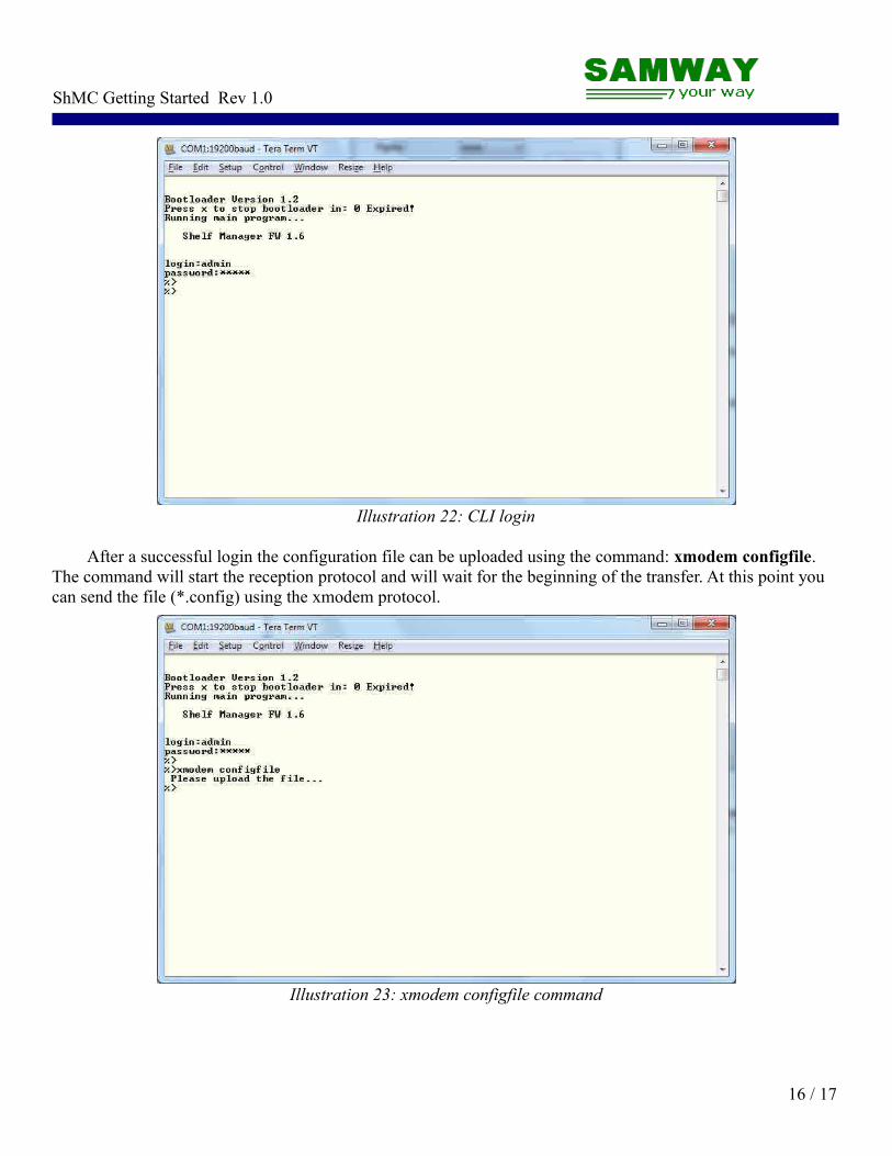
At start-up the CLI of the ShMC will request a login. The default login data for the admin account:login: adminpassword: ADMIN
The default password can be changed using the config file.
15 / 17
Illustration 21: Default Terminal Settings
ShMC Getting Started Rev 1.0
After a successful login the configuration file can be uploaded using the command: xmodem configfile. The command will start the reception protocol and will wait for the beginning of the transfer. At this point you can send the file (*.config) using the xmodem protocol.
16 / 17
Illustration 22: CLI login
Illustration 23: xmodem configfile command

ShMC Getting Started Rev 1.0
After the file transfer is complete a confirmation message will be displayed: Done! . The settings will be updated at the next restart of the ShMC. You can trigger a restart by using the reboot command.
At the next restart, the new settings are loaded and the uploaded configuration file becomes active.
17 / 17
Illustration 24: Send file using xmodem
Illustration 25: Complete setup