getting started - prototoys homepageprototoys.com.au/training_materials/edgecam getting started 2014...
TRANSCRIPT

GETTING STARTED
MANUFACTURING SOFTWARE SOLUTIONS WWW.GZEROFIVE.COM
+61 (3) 9584 9733

Edgecam 2014 R1
Page 2 of 79 V10.0 Vero Software Ltd
Copyright
Copyright © 2014 Vero Software Ltd. All rights reserved.
Any copyright or other intellectual property right of whatever nature which subsists or may subsist in the presentation and/or content of the programs (including without limitation its look, feel, visual or other non-literal elements) remains the property of Vero Software Ltd or its licensor(s) absolutely.
No part of this publication may be reproduced, transmitted, transcribed, stored in a retrieval system or translated into any language, in any form or by any means, electronic, mechanical, optical, chemical, manual or otherwise, without the express written permission of Vero Software Ltd.
Unauthorised reproduction or distribution of these programs or any part thereof is unlawful and may result in civil or criminal penalties.
Edgecam and the Edgecam Logo are trademarks of Vero Software Ltd.
Windows is a trademark of Microsoft Corporation.
All product names mentioned in this publication, and not listed above, are acknowledged as the trademarks of the respective manufacturers and producers of such products.
Vero Software Ltd makes no representations or warranties with respect to the contents hereof and specifically disclaim any implied warranties of satisfactory quality or fitness for any particular purpose. Further, Vero Software Ltd reserves the right to revise this publication and to make changes in the contents hereof without obligation to notify any person of such changes or revisions.
The information contained within this document is subject to change without notice and does not represent a commitment on the part of the vendor. The software described in this document is furnished under a licence agreement and may be used or copied only in accordance with the terms of the agreement.

Edgecam 2014 R1
V2014 R1 V10.0 Page 3 of 79
Contents
Contents ................................................................................................................................. 3
License Restrictions ................................................................................................................ 6
Example Part Files .................................................................................................................. 6
Conventions Used in This Guide ............................................................................................ 7 Terminology ............................................................................................................................................ 7
Licensing Requirements ......................................................................................................... 9
Getting Started ........................................................................................................................ 9
What is Edgecam? .................................................................................................................. 9
The CAD/CAM life-cycle ......................................................................................................... 9
Edgecam Mouse Control ...................................................................................................... 10
The Edgecam Program Group .............................................................................................. 11 The Edgecam Launcher .........................................................................................................................12 Classic Edgecam ...................................................................................................................................12 Workflow Edgecam ................................................................................................................................13 Stock Manager .......................................................................................................................................13 Machine Manager ..................................................................................................................................13 Fixture Manager .....................................................................................................................................13 Toolkit Manager .....................................................................................................................................13 Settings .................................................................................................................................................13 Recently Used File List ..........................................................................................................................13 Tools .....................................................................................................................................................14 Job Manager ..........................................................................................................................................14 Technology Assistant .............................................................................................................................14 Toolkit Assistant .....................................................................................................................................14 Toolstore Administrator ..........................................................................................................................14 Toolstore ...............................................................................................................................................14 Live Job Reports ....................................................................................................................................14 Utilities ...................................................................................................................................................14 Other Shortcuts on the Launcher ............................................................................................................14 Part Modeler ..........................................................................................................................................14 Strategy Manager ..................................................................................................................................15 Editor .....................................................................................................................................................15 Code Wizard ..........................................................................................................................................15 Comms Setup ........................................................................................................................................15 Launcher Help .......................................................................................................................................15 What’s New ...........................................................................................................................................15 Edgecam Tutorials .................................................................................................................................15
Options in Edgecam Program Group Folder ................................................................................. 15 Code Generator .....................................................................................................................................15
Comms Folder .............................................................................................................................. 15 Sample Lathe.........................................................................................................................................15 Sample Mill ............................................................................................................................................16 Sample Wire ..........................................................................................................................................16
Getting Started ...................................................................................................................... 16
Opening Edgecam for the First Time .................................................................................... 16
Welcome…Screen ................................................................................................................ 17
Understanding the Edgecam Screen Layout ........................................................................ 18
Quick Access Toolbar ........................................................................................................... 18
Ribbons ................................................................................................................................. 19 Setup .....................................................................................................................................................19 Features ................................................................................................................................................19 Machining ..............................................................................................................................................19 NC .........................................................................................................................................................19 File Ribbon ............................................................................................................................................20 Open Autosave: .....................................................................................................................................21

Edgecam 2014 R1
Page 4 of 79 V10.0 Vero Software Ltd
Save: ..................................................................................................................................................... 21 Save As: ................................................................................................................................................ 21 Preferences: .......................................................................................................................................... 22 Colours: ................................................................................................................................................. 23 Autodesk Vault: ..................................................................................................................................... 23 Exit: ....................................................................................................................................................... 23 Setup Ribbon......................................................................................................................................... 24 Features Ribbon .................................................................................................................................... 24 Machining Ribbon& NC Code Ribbon .................................................................................................... 24 Command Groupings............................................................................................................................. 24 The Geometry Group ............................................................................................................................. 24 Windows ............................................................................................................................................... 25 Feedback Window ................................................................................................................................. 25 The Context Menu in the Feedback Window .......................................................................................... 25 Style ...................................................................................................................................................... 26 Help ...................................................................................................................................................... 26 Status Bar, Views and Split Screen ........................................................................................................ 26 Views .................................................................................................................................................... 27 Split Screen ........................................................................................................................................... 27 Views – Workflow Tiles .......................................................................................................................... 27 Entering Data ........................................................................................................................................ 28 Entering Data Directly ............................................................................................................................ 28 Using Checkboxes ................................................................................................................................. 28 Using Radio Buttons .............................................................................................................................. 29 Drop Down Menus ................................................................................................................................. 29 Browse to a File ..................................................................................................................................... 29
Configuring Your Environment .............................................................................................. 30
Specifying Preferences ......................................................................................................... 30 Setting System Defaults ........................................................................................................................ 31
Exercise 1 – Creating User Defined System Defaults – Classic Edgecam Only ........................... 32 Setting CPL Marker Size........................................................................................................................ 34
File Locations ....................................................................................................................... 36 Exercise 2 – Selecting System Defaults – Classic Edgecam Only................................................ 37
Customise Interface .............................................................................................................. 38 Ribbon Customisation............................................................................................................................ 38 Tools ..................................................................................................................................................... 38
How to Create and Position Entities ..................................................................................... 39 Positioning Entities ................................................................................................................................ 39 Assigning Entity Attributes ..................................................................................................................... 39 Understanding Co-ordinates .................................................................................................................. 40
Exercise 3 – Positioning Entities Using the Cursor ....................................................................... 41 Exercise 4 – Positioning a Component Using Co-ordinates.......................................................... 45
Manipulating Your View and Mouse Functions ..................................................................... 47 Exercise 5 – Mouse Functions And Views .................................................................................... 47
Using Intellisnap ................................................................................................................... 52 Using Intellisnap to defining co-ordinates ............................................................................................... 52 Using Intellisnap to analyse geometry .................................................................................................... 52 Tab Key ................................................................................................................................................. 52
Understanding Solid Models ................................................................................................. 53 Solid Body Topology .............................................................................................................................. 53 Edge ..................................................................................................................................................... 53 Face ...................................................................................................................................................... 53 Loop ...................................................................................................................................................... 53 Vertex.................................................................................................................................................... 53 Solid ...................................................................................................................................................... 53
Exercise 6 - Using Intellisnap ....................................................................................................... 54
Layer Control ........................................................................................................................ 55 Creating Layers ..................................................................................................................................... 55 Active Layer .......................................................................................................................................... 55

Edgecam 2014 R1
V2014 R1 V10.0 Page 5 of 79
Exercise 7 - Working With Layers ................................................................................................. 56
Selecting Multiple Entities ..................................................................................................... 58 Window Drag Selection ..........................................................................................................................58 Left to Right Window Drag .....................................................................................................................58 Right to Left Window Drag .....................................................................................................................58
Exercise 8 – Windowing Entities ................................................................................................... 59 Exercise 9 - Chaining Entities ....................................................................................................... 61
Keyboard Selection & Entity Types ....................................................................................... 66 Exercise 10 - Deleting Entities ...................................................................................................... 67
Measuring Distances and Verifying Entities .......................................................................... 69
Solid Machinist ...................................................................................................................... 70 Supported CAD Formats ........................................................................................................................70
Solid CAD Systems and Edgecam Licenses ........................................................................ 71 CAD Integration .....................................................................................................................................72
Installation Notes for Solid Machinist .................................................................................... 73 Solid Machinist Prerequisites (CAD) .......................................................................................................73 Autodesk Inventor ..................................................................................................................................73
Edgecam CAD Links ............................................................................................................. 73 Advantages for Using CAD Links ...........................................................................................................73 Cad Link ................................................................................................................................................73 Reloading Pro/ENGINEER Files (Creo Parametric) ................................................................................74 CAD Link Launch Button ........................................................................................................................74 Cad Table – Parts ..................................................................................................................................74
Associative Reloading of Solid Part Files.............................................................................. 75 Reporting Design Changes ....................................................................................................................75 Best Practices for CAD Designs .............................................................................................................75
Leaving Edgecam ................................................................................................................. 76 Getting Further Help...............................................................................................................................76
Document Revision Control .................................................................................................. 79

Edgecam 2014 R1
Page 6 of 79 V10.0 Vero Software Ltd
License Restrictions
You may discover that you are unable to work with some of the exercises due to license restrictions.
In order to remove any license restrictions, you can set Edgecam to run in Homework Mode. To activate
Homework Mode, Right click over the CLS in the windows task bar notification area, and select the option from the menu.
Homework Mode enables the user of a licensed system to run Edgecam with access to all functionality except for NC code generation.
Homework mode emulates the educational Homework license.
Useful when training for example, to evaluate higher levels of license than currently in use.
Homework Mode allows you to experience all available licenses in Edgecam. This feature will allow you to save files. The file extension is not a standard .PPF extension but is an .EPF.
You will not be able to re-load an .EPF file into a licensed version of Edgecam.
You cannot generate CNC data from an .EPF File.
Example Part Files
There are a number of sample part files mentioned within this training guide. This data can be accessed either from a Training CD or specified folder.
If selecting from a USB drive this will generally be E:\Getting Started.
Some files may not be opened away from the classroom due to licensing restrictions.

Edgecam 2014 R1
V2014 R1 V10.0 Page 7 of 79
Conventions Used in This Guide
To enable you to use the information in this guide effectively, you need to understand the used in the guide to represent different types of information.
Buttons on the screen are represented as the button text in bold within square brackets. For example: Click on [OK].
Keys on the keyboard are represented as bold lettering in between <> characters. For example: Press <Enter>.
Ribbon options are represented as a path with the main ribbon and sub menus in Bold and Capitalised and separated with ►.
For example: Select Setup ► Edit ► Scale.
Field names are represented as bold text. And the value to be entered will be represented by Bold Text. For example: Enter the value 50 in the Offset field. Or When prompted for the X, Y or Z values type X100Y50Z0 <Enter>.
Denotes a Left Mouse Button Click
Denotes a Right Mouse Button Click
This is a note. It contains useful or additional information.
This is a reference. It directs you to another area or document.
This is a thought box. It is generally used in exercises and contains a question for you to consider.
This is a warning, it contains information that you must not ignore.
This is a tip. It is generally used in exercises and offers further advice.
1. This is the first line of a number list item
2. This is the second item of the numbered instructions, which you must
3. Follow in sequence.
This is a list
of items, in which
The order is not important.
Terminology
Whilst reading this manual some of the terminology and terms maybe new to you.
Examples of these are:
Pick = Select = Left Click. Construction Plane (CPL) = Origin = Datum
Confirm your selection = Click the Tick or Right Click.

Edgecam 2014 R1
Page 8 of 79 V10.0 Vero Software Ltd
Trainee Notes

Edgecam 2014 R1
V2014 R1 V10.0 Page 9 of 79
Licensing Requirements
This manual is aimed at users of all levels of license of Edgecam.
It is the Pre-requisite course and must be completed.
Edgecam License levels are 1.Essential, 2.Standard, 3.Advanced, 4.Ultimate.
Getting Started
This manual is used to give an insight into some of the basic functionality before attending a Base Essential Milling or Turning course.
Some of the functions are.
The Launcher and User Interface of Edgecam
Mouse Controls
Entity Types
Solid Model Topology
Single and Multiple Selection techniques
License requirements
What is Edgecam?
Edgecam is a CAD/CAM system that enables you to design and plan the manufacture of components. Edgecam allows you to:
Create Wireframe or Surface Design models and/or import 3rd
party format files including Solid Models, DXF and Iges.
Create Stock & Fixturing
Select the machine and tools required to produce the component.
Simulate the CAM instructions.
Generate the CNC code required to operate the selected machine.
Communicate with machine tool controllers.
Manage a tooling database.
The CAD/CAM life-cycle
This is the typical Edgecam process cycle. It demonstrates the sequential chain of events that will occur in order to produce CNC code from Edgecam.

Edgecam 2014 R1
Page 10 of 79 V10.0 Vero Software Ltd
Edgecam Mouse Control
The mouse controls in Edgecam are detailed below.
Depending on which mode you are in or at what point in a command you are up to, the mouse control may differ.

Edgecam 2014 R1
V2014 R1 V10.0 Page 11 of 79
The Edgecam Program Group
Edgecam consists of various applications that interact with each other.
This is the Edgecam program group. Start ►All Programs► Edgecam (Version). All applications are
separated into their respective folders.
These same applications can be found by Double Left clicking the Edgecam Launcher on the Desktop.

Edgecam 2014 R1
Page 12 of 79 V10.0 Vero Software Ltd
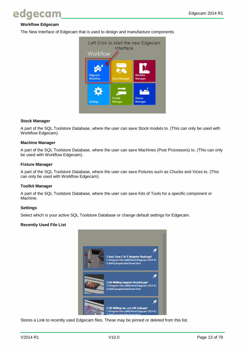
The Edgecam Launcher
Left Click any Tile on the Launcher to activate that command.
The Launcher can be navigated by Rolling the scroll wheel on the mouse or Left Clicking the arrows.
Classic Edgecam
The old Interface of Edgecam that is used to design and manufacture components.
Edgecam 2014 R1
V2014 R1 V10.0 Page 13 of 79
Workflow Edgecam
The New Interface of Edgecam that is used to design and manufacture components.
Stock Manager
A part of the SQL Toolstore Database, where the user can save Stock models to. (This can only be used with Workflow Edgecam).
Machine Manager
A part of the SQL Toolstore Database, where the user can save Machines (Post Processors) to. (This can only be used with Workflow Edgecam).
Fixture Manager
A part of the SQL Toolstore Database, where the user can save Fixtures such as Chucks and Vices to. (This can only be used with Workflow Edgecam).
Toolkit Manager
A part of the SQL Toolstore Database, where the user can save Kits of Tools for a specific component or Machine.
Settings
Select which is your active SQL Toolstore Database or change default settings for Edgecam.
Recently Used File List
Stores a Link to recently used Edgecam files. These may be pinned or deleted from this list.

Edgecam 2014 R1
Page 14 of 79 V10.0 Vero Software Ltd
Tools
Mainly a number of shortcuts dealing with the Toolstore. Third party exe shortcuts may be added to this area along with folders and URLs. Job Manager
Launches the Toolstore module that enables you to create and manage tool kits for jobs in Edgecam.
Technology Assistant
A module of the Toolstore that allows you to define and assign cutting data to tools.
Toolkit Assistant
A module of the Toolstore that allows you to assign tools to specific Edgecam jobs. (This is the same as Toolkit Manager)
Toolstore Administrator
You are able to select, modify, or delete SQL Toolstore databases used for Toolstore, Material Technology, Toolkit Assistant, Stock Manager, Fixture Manager & Machine Manager.
Toolstore
Opens Toolstore database. Used to store all tool of any type used within Edgecam.
Live Job Reports
Launches the web browser and displays HTML reports for Jobs created in the Job Manager (Toolkit Assistant). This is your set up sheet.
Utilities
An option that allows you to configure system settings such as language and license settings.
Other Shortcuts on the Launcher
Part Modeler
Edgecam’s 3D solid modelling module that is used to create and design parts along with stock and fixturing to take into Edgecam.

Edgecam 2014 R1
V2014 R1 V10.0 Page 15 of 79
Strategy Manager
Strategy Manager is a Logic flow chart based software that allows the user to automate the machining of Features from Solid Models.
Editor
Opens the Edgecam Editor to allow you to view and edit text files.
Code Wizard
This option will allow you to create and modify your own post processors using supplied templates shipped with Edgecam. The Code Wizard comes with all systems.
Comms Setup
A utility to configure RS 232 communications to machine tool controllers.
Launcher Help
Left click on the Help Icon to show other functions including Help files and Tutorials.
What’s New
A help file, that amongst other things, contains a list of new or improved functionality released in this particular version of Edgecam.
It is recommend that you always read the What’s New help files after you have updated Edgecam to a later version so you are aware of any changes.
Edgecam Tutorials
A shortcut to the on-line tutorials that contain step by step instructions on how to use Edgecam.
These may be on either the Classic or Workflow interface.
Options in Edgecam Program Group Folder
Code Generator
This option is used to compile custom post processors. It is license dependant and requires you to have written a suitable source file fit for compilation.
Comms Folder
Sample Lathe
Launches an example RS232 communications link for a typical lathe.
Edgecam 2014 R1
Page 16 of 79 V10.0 Vero Software Ltd
Sample Mill
Launches an example RS232 communications link for a typical milling machine.
Sample Wire
Launches an example RS232 communications link for a typical Wire EDM machine.
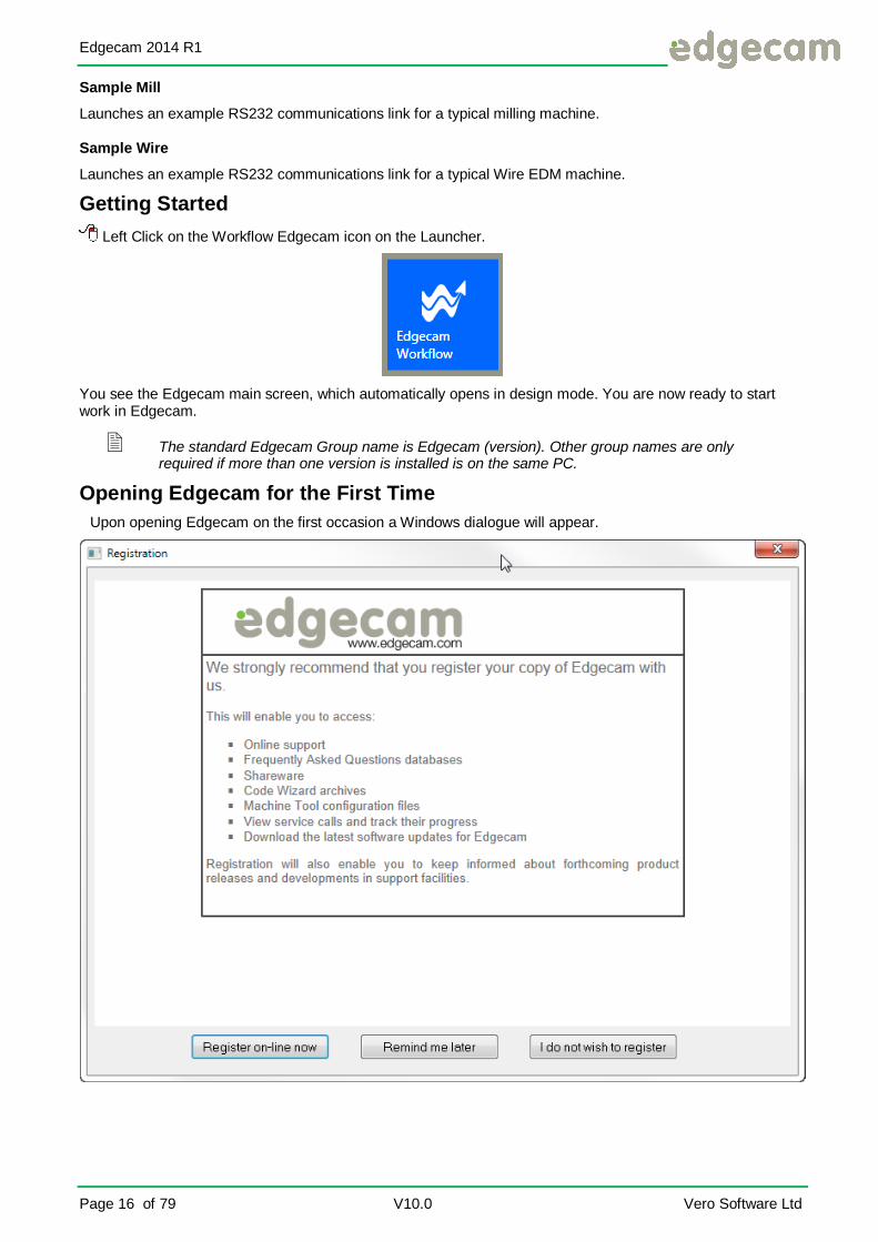
Getting Started
Left Click on the Workflow Edgecam icon on the Launcher.
You see the Edgecam main screen, which automatically opens in design mode. You are now ready to start work in Edgecam.
The standard Edgecam Group name is Edgecam (version). Other group names are only required if more than one version is installed is on the same PC.
Opening Edgecam for the First Time
Upon opening Edgecam on the first occasion a Windows dialogue will appear.

Edgecam 2014 R1
V2014 R1 V10.0 Page 17 of 79
This Window will appear after every new installation of Edgecam, an update in the software or if has been
selected from Utilities ► Factory Settings.
It is strongly recommended to register online to get the full benefit of support. This includes help with machining
parts after a course has been attended or to booking your next course online. On this occasion Left Click, [I do not wish to register].
Welcome…Screen
Using Browse for an existing part file or a solid model, Using Windows Explorer, an existing Edgecam file (.ppf) or a solid model can be searched for and loaded.
New Metric Milling or Turning Defaults can be selected. (A blank Edgecam session).
The Workflow Steps can be viewed in the bottom left.
The Welcome screen offers a recently used file list along with recently used folders.
Select X Close Window, near the top left.

Edgecam 2014 R1
Page 18 of 79 V10.0 Vero Software Ltd
Understanding the Edgecam Screen Layout
Left Click any Ribbon to select.
The Edgecam main screen is your main workspace, in which you design and plan the manufacture of components. The Edgecam main screen consists of the following main features:
Quick Access Toolbar
This is located at the top left of Edgecam. It contains icons you would use regularly such as Save, Undo, Redo Verify & Measure etc.
You may Add or remove to this area by Left clicking on the small black triangle.
Edgecam 2014 R1
V2014 R1 V10.0 Page 19 of 79
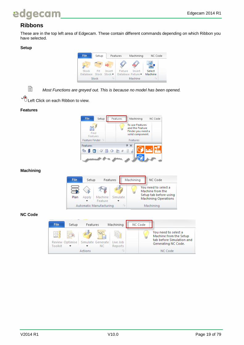
Ribbons
These are in the top left area of Edgecam. These contain different commands depending on which Ribbon you have selected.
Setup
Most Functions are greyed out. This is because no model has been opened.
Left Click on each Ribbon to view.
Features
Machining
NC Code

Edgecam 2014 R1
Page 20 of 79 V10.0 Vero Software Ltd
File Ribbon
Start:
New Metric Milling or Turning Defaults can be selected. (A blank Edgecam session).
Offers a recently used file list along with recently used folders.
Open:
Using Windows Explorer, an existing Edgecam file (.ppf) or a solid model can be searched for and loaded.

Edgecam 2014 R1
V2014 R1 V10.0 Page 21 of 79
Insert:
Inserts different file types into Edgecam. Useful if a part already exists within Edgecam.
Send:
Sends files to Edgecam support.
Open Autosave:
Opens the last automatically saved Edgecam file in the event of a power cut etc.
Save:
Saves the file to the users choice of name and location or overwrites, if already saved.
Save As:
Saves the file to the users choice of name and location.

Edgecam 2014 R1
Page 22 of 79 V10.0 Vero Software Ltd
Macros:
Run or Record Custom macros (PCI or Java Script)
Print:
Prints the graphics area using Part Modelers print function.
Save Job Image:
When a kit has been selected this function will wake up and allow a screen shot to be saved to the setup sheet.
Preferences:
Preferences loaded in your Default file. These can be changed for individual files also.

Edgecam 2014 R1
V2014 R1 V10.0 Page 23 of 79
Colours:
Change the colour of selected or highlighted Entities, Background, Rapid, High Feed and Lead moves.
Autodesk Vault:
For Autodesk users, the use of the Vault functionality from within Edgecam.
Requires Edgecam Vault Interface module EdgecaCAM_ENVLT-0
Exit:
Closes Edgecam
Edgecam 2014 R1
Page 24 of 79 V10.0 Vero Software Ltd
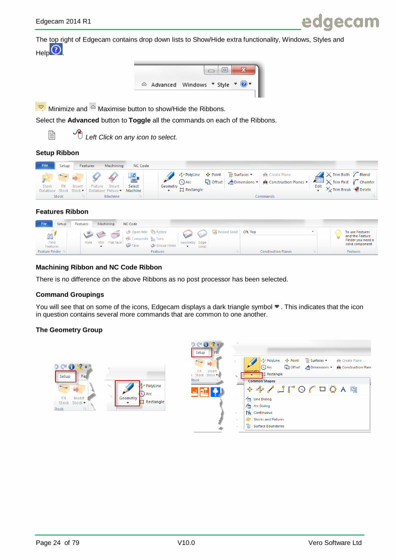
The top right of Edgecam contains drop down lists to Show/Hide extra functionality, Windows, Styles and
Help .
Minimize and Maximise button to show/Hide the Ribbons.
Select the Advanced button to Toggle all the commands on each of the Ribbons.
Left Click on any icon to select.
Setup Ribbon
Features Ribbon
Machining Ribbon and NC Code Ribbon
There is no difference on the above Ribbons as no post processor has been selected.
Command Groupings
You will see that on some of the icons, Edgecam displays a dark triangle symbol . This indicates that the icon in question contains several more commands that are common to one another.
The Geometry Group

Edgecam 2014 R1
V2014 R1 V10.0 Page 25 of 79
Windows
Allows the user to Toggle on/off any Window in the List, onto the active Ribbon view.
Windows contain extra information that may help in the setting up or machining of a component.
Edgecam is split into two modes of Design and Manufacture. The Setup and Features Ribbons are Design Mode, Machining and NC code are Manufacture Mode.
Feedback Window
The Feedback window is used to display information from commands such as Verify , Strategy Manager Log file and feedback such as Solid Model Tolerance and the results of Feature Find.
The Context Menu in the Feedback Window
The context menu ( Right click) in the Feedback Window offers the following commands:
Copy: Highlight the required text to copy
Clear: Clears all text from the Window
Edgecam 2014 R1
Page 26 of 79 V10.0 Vero Software Ltd
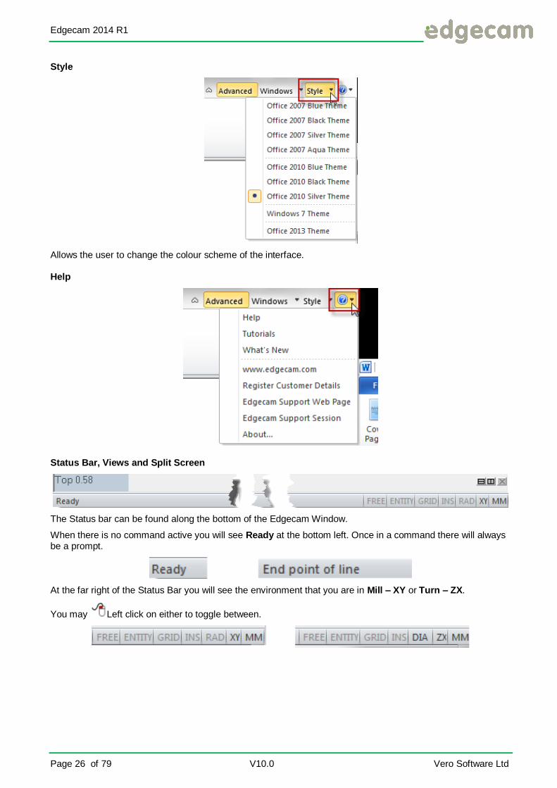
Style
Allows the user to change the colour scheme of the interface.
Help
Status Bar, Views and Split Screen
The Status bar can be found along the bottom of the Edgecam Window.
When there is no command active you will see Ready at the bottom left. Once in a command there will always be a prompt.
At the far right of the Status Bar you will see the environment that you are in Mill – XY or Turn – ZX.
You may Left click on either to toggle between.
Edgecam 2014 R1
V2014 R1 V10.0 Page 27 of 79
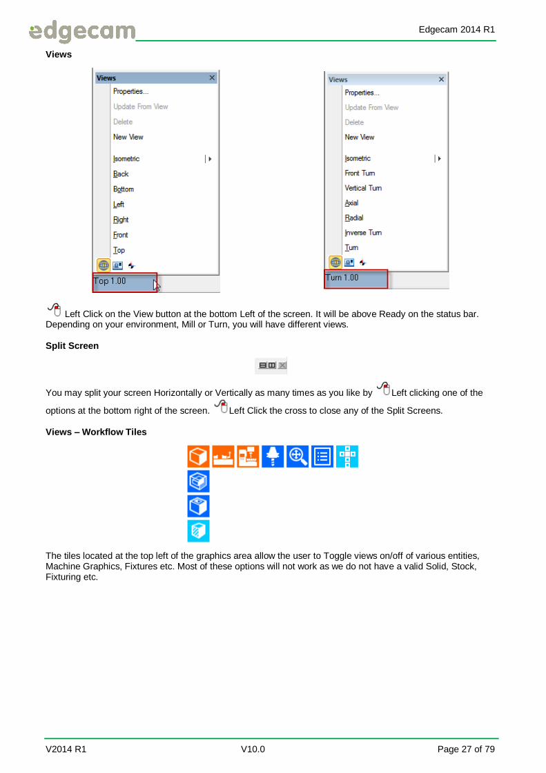
Views
Left Click on the View button at the bottom Left of the screen. It will be above Ready on the status bar. Depending on your environment, Mill or Turn, you will have different views.
Split Screen
You may split your screen Horizontally or Vertically as many times as you like by Left clicking one of the
options at the bottom right of the screen. Left Click the cross to close any of the Split Screens.
Views – Workflow Tiles
The tiles located at the top left of the graphics area allow the user to Toggle views on/off of various entities, Machine Graphics, Fixtures etc. Most of these options will not work as we do not have a valid Solid, Stock, Fixturing etc.

Edgecam 2014 R1
Page 28 of 79 V10.0 Vero Software Ltd
Entering Data
Once you have Left clicked on an icon to select a command, Edgecam will typically display a dialog. This is an example of a dialog:
A dialog is a data entry window that allows you to enter details relating to the selected command. When a dialog appears on the screen, it takes priority over everything else. You must exit a dialog before you can work
anywhere else on the screen, by Left clicking on one of the following buttons:
[OK], to confirm the details you have entered and continue the command [Cancel], to abandon the details you have entered and cancel the command.
Edgecam dialogs contain one or more tabs, as shown in the example above, that contain a group of related fields. You can access a tab, and the details contained in the tab, by clicking on the tab name you require.
Within each tab, you can enter data:
Directly Using checkboxes Using radio buttons
Drop down menus Browse to a specific system file or file location Spinner controls
Entering Data Directly
You enter data directly within a dialog by clicking in the required field, then typing the information into the field.
You can also press the <Tab> button on the keyboard to move the cursor between fields.
Using Checkboxes
You use checkboxes to select and deselect options in Edgecam. A ticked checkbox indicates that an item is selected. An empty checkbox indicates that an item is not selected.
You can select more than one checkbox.

Edgecam 2014 R1
V2014 R1 V10.0 Page 29 of 79
Using Radio Buttons
You use radio buttons to make a selection from a list of options. You can select only one option. For example, in the instance below you can specify to work in either the XY or ZX environment, and in either inches or millimetres.
Drop Down Menus
You can only select an option from an item in the list:
Browse to a File
Use the [Browse] option to select a file. This option will open Windows explorer.
Using the [Browse…] option will launch a standard window such as the option below.
Edgecam files (.ppf) or solid models may be stored anywhere on the C: drive or the Network
Locate and select the file you require then select [Open] or <ENTER> on the keyboard to return to the Edgecam menu.

Edgecam 2014 R1
Page 30 of 79 V10.0 Vero Software Ltd
Configuring Your Environment
You can change the features of your workspace in the following ways:
Selecting the Environment Autosave Setting system defaults.
Selecting Preferences. Changing the screen background colour.
Splitting the graphics area Configured Views
The manner in which IGES and DXF files are loaded Mouse wheel sensitivity.
The above can be permanently saved to a default file in Classic Edgecam Only.
You can select the environment in which to work using the XY / ZX toggle on the Status bar, or loading a specific defaults file.
Specifying Preferences
To specify various Preferences select File ► Preferences. The dialog will open.
You can also select the environment in which to work by selecting either the XY or ZX radio button in the Environment section.

Edgecam 2014 R1
V2014 R1 V10.0 Page 31 of 79
The key options on the General Tab that you may wish to configure are Part Units, Environment, Autosave (number of Edgecam commands between automatic saves).On the Interface Tab, Mouse Wheel Sensitivity (any +ve value).
System: Specify the tolerance at which objects exist and are saved in Edgecam.
Display: Specify the tolerance at which Edgecam draws or loads entities.
Autosave : Specifies the number of commands after which an automatic save (Autosave) occurs. Zero disables the Autosave functionality. To load the automatically saved part, select the Open Autosave (File menu) command.
Mouse Wheel Sensitivity: Adjust the mouse wheel sensitivity by entering a value which will act as the zoom factor applied on each roll of the wheel.
When the value used in the Mouse Wheel Sensitivity is smaller than 1, Edgecam’s zoom command will change its direction.
Import: Edgecam supports two alternative IGES and DXF/DWG export systems. Select your preferred option.
Setting System Defaults
You can set system defaults to define the unit of measurement, system and display tolerances and port setup that are loaded when you open parts in Edgecam. Edgecam provides two sets of defaults - one for imperial measurements, the other for metric.
Refer to the Help file for a full list of all options.

Edgecam 2014 R1
Page 32 of 79 V10.0 Vero Software Ltd
Exercise 1 – Creating User Defined System Defaults – Classic Edgecam Only
Although a standard metric Mill or Turn default can be loaded in Workflow, a new Default cannot be created. This must be done in Classic Edgecam.
File ► Preferences can be changed in Workflow, but only for the individual file.
The following exercise will demonstrate how to manipulate Edgecam in such a way that the system recognises a user’s own individual preference settings. In this instance the user wishes to work in Mill (XY) mode and use metric units, changing some of the user Preferences and Configuring the view also.
1. Select New Milling Part for Classic Edgecam from the Launcher.
By selecting the New Milling Part some of the modifiers will already be set.
2. Select Options ► Preferences. Fill in the modifiers.
General Tab
Part Units: Millimetres Environment: XY Autosave: 5 Display: .01

Edgecam 2014 R1
V2014 R1 V10.0 Page 33 of 79
Tool Libraries Tab
Display Toolchange: Checked
Selection Tab
Entity Tooltips: Checked Show Help On Tooltip: Checked
Intellisnap: All Checked Show Tool On Cursor: Checked Free Picks Only: Checked
Solids Tab
Workflow, Alignment Options: [Edit]
You may not have Milling or Turning options depending on your license.

Edgecam 2014 R1
Page 34 of 79 V10.0 Vero Software Ltd
Interface Tab
Mouse Wheel Sensitivity: 1.2
3. Select [OK].
Setting CPL Marker Size
4. Left or Right on the view button, bottom left of Edgecam and from the menu select Properties. The Configure View dialogue box will appear.
General View
Axes: Checked
5. Select [OK]. The Axes of the CPL marker will now extend.
The Default file will remember any option selected in Configure View.

Edgecam 2014 R1
V2014 R1 V10.0 Page 35 of 79
6. Select Options ► New Defaults. In the Name modifier type in “Your name”_Mill_mm.
7. Select [OK]. Edgecam has saved your preference settings but not yet loaded them.
A Default file will not only save Preferences settings but will also remember the position of the screen and the number of active View Ports. Ensure you are satisfied with the View Ports BEFORE creating a default file.

Edgecam 2014 R1
Page 36 of 79 V10.0 Vero Software Ltd
File Locations
Default locations can be set within Edgecam through the File Locations command. On the Launcher you can
select Utilities ► File Locations or from the Utilities area of Edgecam within the Edgecam program group.
Locations that can be changed here are such places as the Network location, if the user wants to store shared files across the network, such as Post processors, PCI’s. Toolstore files etc. Strategy Manager file locations can also be set here.
These default locations allow Edgecam to run without the requirement of the user being a local administrator.
Locations that are greyed out can only be changed within the system registry.

Edgecam 2014 R1
V2014 R1 V10.0 Page 37 of 79
Exercise 2 – Selecting System Defaults – Classic Edgecam Only
In reference to the previous exercise, you will now be shown how to select your Default file. Remember that many more users could be using Edgecam. Therefore, in order to guarantee that the system operates in a preferred manner, a user would set Edgecam to use the users own Defaults.
A typical default location would be C:\Users\Edgecam\Documents\Planit\2014.10\Edgecam\cam\Support.
1. Select Options ► Select Defaults. From the drop down list select your Default from the last
exercise.
2. New Part Defaults: Selected File this will be the Default for all new parts.
You will see that there are other Default files in this list. These files represent other Edgecam Users settings or the system defaults.
Select the No change option to load the selected default file, but not to change the defaults loaded automatically with the part.
3. Select [OK].
When loading a 3rd party format file such as an IGES or Solid file, the units of the model will be determined by the units of the active defaults file.

Edgecam 2014 R1
Page 38 of 79 V10.0 Vero Software Ltd
Customise Interface
It is possible to customise the Workflow interface. Right Click on any part of a Ribbon and select Customise the Ribbon.
Ribbon Customisation
All Edgecam dialog boxes can be customised with the ability to create your own use Mask for them. A mask is a new interface for any dialog.
Tools
In the Tools area Edgecam macros such as PCI and Java Script can be added. These can help speed up any Edgecam process.
These options will be covered on a later course.
Edgecam 2014 R1
V2014 R1 V10.0 Page 39 of 79
How to Create and Position Entities
Whilst working inside Edgecam you will come across many different types of Entities, an entity is any item created within either the Design or Manufacture mode.
Examples are:
Solids
Features
Points
Lines
Circles and arcs
Curves
Surfaces
Continuous entities
Toolpaths
Positioning Entities
Whether you are creating, moving or deleting an entity, it is essential that you understand how to correctly manipulate the command. Examples of such commands are:
Create a line/arc and locate it correctly on the screen.
Move (linear feed/rapid) a milling cutter.
Locate the datum position on a component.
Identify an item for deletion
All such cases require a select/position command. The commands are:
Free Select: Places an entity in no specific position.
Entity Select: Accurately select a specific position.
Intellisnap: Accurately position relative to another entity.
Co-ordinate Input: Specifically position an entity using X,Y & Z co-ordinates
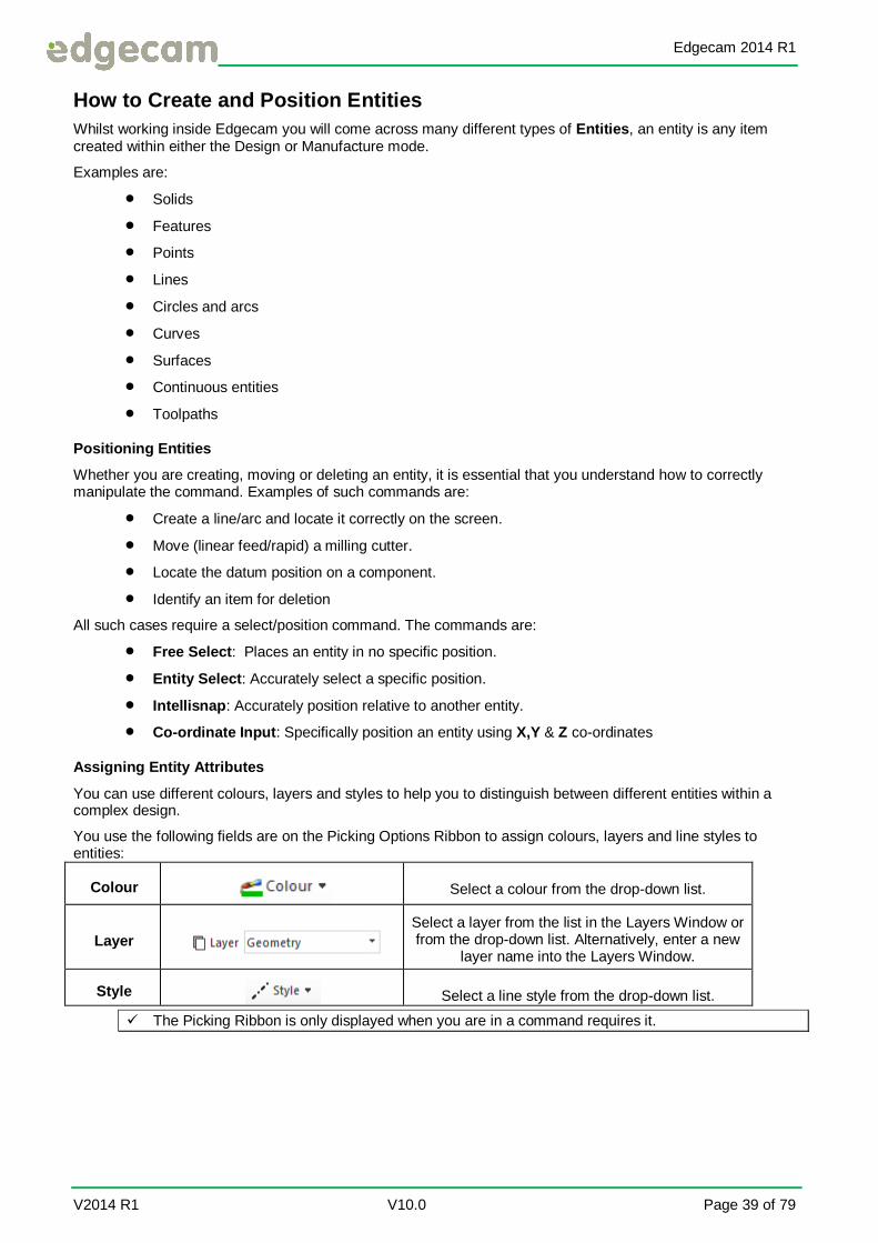
Assigning Entity Attributes
You can use different colours, layers and styles to help you to distinguish between different entities within a complex design.
You use the following fields are on the Picking Options Ribbon to assign colours, layers and line styles to entities:
Colour
Select a colour from the drop-down list.
Layer
Select a layer from the list in the Layers Window or from the drop-down list. Alternatively, enter a new
layer name into the Layers Window.
Style Select a line style from the drop-down list.
The Picking Ribbon is only displayed when you are in a command requires it.

Edgecam 2014 R1
Page 40 of 79 V10.0 Vero Software Ltd
Understanding Co-ordinates
You can use Cartesian (XYZ), Polar (Radius & Angle) or Angular (Axis, Angle & XYZ) co-ordinates in Edgecam. It is assumed throughout this guide that you will use Cartesian co-ordinates.
Remember you will either be working in XY environment (milling) or, ZX environment (turning) You can check which co-ordinate mode you are working in by viewing the bottom right hand corner of the Edgecam screen.
You can enter co-ordinates by:
Left Clicking on the Co-Ordinate Input button on the Picking Options Ribbon or by selecting X, Y or Z on the keyboard.
In Edgecam Milling the Cutter is aligned along the Z axis and machines in X and Y.

Edgecam 2014 R1
V2014 R1 V10.0 Page 41 of 79
Exercise 3 – Positioning Entities Using the Cursor
We shall create some simple wireframe geometry to get practise using the mouse to position entities.
1. If Edgecam is open carry on or start a new session of Workflow Edgecam. Close down the Welcome screen if visible
Ensure that Intellisnap is switched on.
Right Click in the Graphics area to switch Intellisnap on.
2. Select Setup ► Geometry ► Line Dialog.
3. Fill in the modifiers.
Horizontal: Checked Length: 100
4. Select [OK], Follow the prompt.
Point through which line will pass. Place the cursor anywhere on the screen and Left click. You are now executing a Free pick. Create several more random lines.
Free Pick can be seen active at the bottom right of your screen.

Edgecam 2014 R1
Page 42 of 79 V10.0 Vero Software Ltd
A free pick allows the user to pick anywhere in the graphics area.
5. Place the cursor over the CPL marker (datum marker found in the centre of the screen, this is position
X0Y0Z0) Left click this. You are now executing an Entity Select. Right Click or Tick to finish.
6. Select Setup ► Geometry ► Arc Dialog.
7. Fill in the modifier.
Diameter: 25
8. Select [OK]. Follow the prompt.
Centre point for arc. Place the cursor anywhere on the screen and Left click. You are executing a Free pick once more. Create several more random Arcs.

Edgecam 2014 R1
V2014 R1 V10.0 Page 43 of 79
9. Place the cursor over the start, middle or end of an existing line. Observe the Entity Tool tip. Whilst the Entity Tool tip is present, pick the line either at the Mid-point or an End point. You are now picking using the selection options of Intellisnap.
10. Left Click on Entity at the bottom right of your screen.
11. Try Left Clicking anywhere in space in the graphics area. You will get a warning message.
12. No you cannot Free pick, Select [OK].
13. Place the cursor near the end of a Line and select.
14. The arc is positioned at the end of the Line using Entity selection Right Click or Tick to finish.
15. Select Setup ► Delete .Follow the prompt.
Select entity to delete. Place your cursor over any line or arc and Left click. You are now
executing an Entity pick. Right Click or Tick to finish.
Edgecam will always prompt you to perform the appropriate steps within the selected command. Always observe Picking Prompt, the status bar at the bottom of the screen or Help on Tool tip, if activated.
When selecting an entity you will have seen the colour change to green. This can be changed in
File ►Colours.

Edgecam 2014 R1
Page 44 of 79 V10.0 Vero Software Ltd
16. To De-Select an Entity Left Click once more.
The <Escape> key will also de-select.
In an active command will de-select all.
17. To Edit an Entity Double Left Click on an Entity.
A different dialog box will be offered depending on what Entity you Edit.
Edit Line Edit Arc
You may Edit all Entity types
18. Save as ‘3 – Completed Positioning Entities Using the Cursor.ppf’.
Edgecam 2014 R1
V2014 R1 V10.0 Page 45 of 79
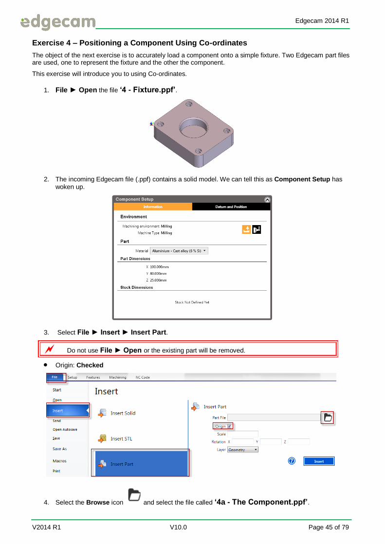
Exercise 4 – Positioning a Component Using Co-ordinates
The object of the next exercise is to accurately load a component onto a simple fixture. Two Edgecam part files are used, one to represent the fixture and the other the component.
This exercise will introduce you to using Co-ordinates.
1. File ► Open the file ‘4 - Fixture.ppf’.
2. The incoming Edgecam file (.ppf) contains a solid model. We can tell this as Component Setup has woken up.
3. Select File ► Insert ► Insert Part.
Do not use File ► Open or the existing part will be removed.
Origin: Checked
4. Select the Browse icon and select the file called ‘4a - The Component.ppf’.

Edgecam 2014 R1
Page 46 of 79 V10.0 Vero Software Ltd
5. Select .Follow the prompt.
Select location at which to insert part. Select or type in the Co-ordinate X50Y40Z-10. Right
Click or Tick to finish.
6. A yellow marker will be displayed to show where the part will be placed.
7. If you are happy with the location, Right Click to finish.
8. Save as ‘4 – Completed Positioning Using Coordinates.ppf’.

Edgecam 2014 R1
V2014 R1 V10.0 Page 47 of 79
Manipulating Your View and Mouse Functions
You can view your component on the screen in different ways by:
Zooming in and out, Roll the scroll Wheel.
Rotating the view. Right Click, Hold down and move the mouse.
Panning the view Hold down the scroll wheel and move the mouse.
Selecting a view orientation. Left Click to pick one of the views
Using a 3D motion controller.
Split the View, Select a Horizontal or Vertical Split.
Refer to Page10 for Mouse Controls
Exercise 5 – Mouse Functions And Views
In this exercise we shall review all the mouse functions and view controls.
1. Carry on with the previous exercise or open ‘5 – Mouse Functions And Views.ppf’.
2. Place the cursor over any Edgecam Ribbon. Right click. You will observe a drop-down menu which enables the user to alter the Ribbon.
3. Select the Features Ribbon. Note how the commands are now active because we have a solid inside Edgecam.
Select Advanced if you cannot see all the commands.

Edgecam 2014 R1
Page 48 of 79 V10.0 Vero Software Ltd
4. In the Features Window, Right Click on the icon representing one of the solids. Options appear for this Window.
5. From the Windows drop down, top left of Edgecam select Layers.
6. In the Layers Window Right Click on one of the Layer names. Options will appear for Layer Control.
The active Layer can be seen with a red box next to the left of the name.

Edgecam 2014 R1
V2014 R1 V10.0 Page 49 of 79
7. Windows can be pinned or un-pinned by Left Clicking on the pin icon. Once un-pinned, hover the cursor over the name of the Window to wake up.
Pinned Un-Pinned
8. Select the X at the top right hand side of a Window to close, if required.
9. A Window can be re-positioned by either Left Clicking on the name of the Window and dragging. It is now un-docked.
10. To re-dock Left Click on the name of the Window and drag to a docking position offered by Edgecam around the graphics area.

Edgecam 2014 R1
Page 50 of 79 V10.0 Vero Software Ltd
11. Position the cursor anywhere within the Graphics Area. Right click. You will see a context menu containing commands such as Undo, View controls and at the bottom a short list of up to the last 5 commands used.
Intellisnap can be switched on or off with a Left click.
12. Left click anywhere in the graphics area for the menu to disappear.
13. Practise your mouse view manipulation controls.
14. Zoom, Pan and Rotate the part as described at the beginning of the exercise.
15. Use Zoom Extents to show the entire model.
16. As you have now rotated the part the View button at the bottom right of the screen will say Dynamic.
The number is un-important, this is just a factor of the zoom.
17. From the Views tile select any View and repeat to show other views.

Edgecam 2014 R1
V2014 R1 V10.0 Page 51 of 79
18. Split the screen either Horizontally or Vertically as many times as required. . Use the mouse controls to resize and select different views for each port.
19. Select Render Component to toggle between Wireframe and Rendered.
20. An un-rendered solid.
21. Close down the extra View ports by selecting the X at the bottom right of the view.

Edgecam 2014 R1
Page 52 of 79 V10.0 Vero Software Ltd
Using Intellisnap
Using Intellisnap to defining co-ordinates
The Intellisnap feature allows you to define a position within the graphics area by selecting an existing entity. For example, you can define the start point for a new entity or machining command as the end point of an existing line.
You can select the:
Ends of entities Mid-points of entities Centre points of circles and arcs.
To use Intellisnap, simply move the cursor near the end, mid or centre point of an existing entity. Edgecam highlights the selected entity in the Intellisnap flyover colour, displays a square, cross or circle in the flyover colour at the selected point, and displays information about the selected point in a tool tip, like this:
End of Entity Mid-Point of Entity Centre Point of Entity
Left click while the flyover square, cross or circle is displayed to define the position.
Change the colour of the Intellisnap flyover using the Colour Configuration dialogue.
Using Intellisnap to analyse geometry
Intellisnap can be used as a design aid, and also as a means of interrogating entities that are in a part file.
Activate Intellisnap by Right clicking anywhere in the view port and selecting Intellisnap from the drop down menu.
Intellisnap is active by default.
With Intellisnap activated, when the cursor is placed over an entity it will highlight and return information to the screen in a tool tip type box.
By pressing the <V> key whilst the information is being displayed this will extend the dialog box to show more data relating to the entity
The larger information box will stay active until the <V> key is pressed again.
Tab Key
When there are many entities near the cursor, the <Tab> key sign appears on the cursor. The information box will then carry a numerical reference to the number of entities present at the cursor location. Use the tab key to scroll through these entities.

Edgecam 2014 R1
V2014 R1 V10.0 Page 53 of 79
Understanding Solid Models
Solid Body Topology
When a solid model is loaded into Edgecam, it does not contain any wireframe or surface entities. Solid bodies contain a different set of entity types that are only relevant to solid part files.
Using Intellisnap to interrogate the component is a useful method to gain an appreciation of the entities that are contained within the Solid Model.
Edge
A single line that forms the edge on a solid part.
Face
A face on the solid part.
Loop
A series of edges that form a continuous closed loop around a solid face.
Vertex
An intersection point where edges meet.
Solid
This is the entire solid body itself.
Use the <V> key & <Tab> key to help you interrogate the solid body.

Edgecam 2014 R1
Page 54 of 79 V10.0 Vero Software Ltd
Exercise 6 - Using Intellisnap
1. Carry on with the last opened exercise or open '6 – Intellisnap.ppf’ and hover over any part of the
solid.
It will highlight red by default, this can be changed in File ► Colours.
2. Note the name of the entity selected. Press <Tab> on the keyboard when you see the Tab symbol.You will see the other entities in that area of the cursor.
3. Press <V> on the keyboard so see more information on the entity.
If the <Tab> or <V> keys don’t work switch off Intellisnap and switch back on again.
4. Find all the entities mentioned as the topology of a solid model.
5. The focal point for the zoom is the cursor position. Test this by placing the cursor at different positions, a hole for example, and rotate the scroll wheel. Change the position and scroll again.
6. The focal point for rotation is the middle of the solid model. To change this Right click at a new
position, a hole for example, and hold down the <CTRL> key. Right click Rotate the model to test. Change to a new position.
7. Zoom extents sets the default back to the solid centre.
8. On the Layers Window, Right click on the Wireframe Layer and Show only.
9. Repeat the above processes on Wireframe Entities.
Wireframe was created from the model by using the Features ► Geometry command
previously. There is no wireframe on a solid model.

Edgecam 2014 R1
V2014 R1 V10.0 Page 55 of 79
Layer Control
Layers allow you to segregate entities onto different layers so they can be made visible or invisible. This helps you manage your designs and toolpaths more effectively.
The Layer Window is a quick and effective way of managing the layer control and tasks such as creating, showing and editing layers are all straight forward.
Creating Layers
To create a new layer, perform a Right click anywhere in the Layers Window. This will display a menu where you can select New.
This will present the following dialog box where a name can be entered. The Show check box allows you to say whether the layer should be visible or not.
A new layer will appear in the Window when [OK] is selected.
Active Layer
Within any part file there can only be one active Layer. This is the Layer that appears in the Window with a red
coloured background on the layer icon. To change the active Layer, Double left click over the layer icon that you wish to be active. The red marker will then appear on the chosen layer. An alternate method of
making a Layer active would be to highlight a layer by Left clicking it, then Right clicking so the drop down menu appears. From this menu select the option Make Active.

Edgecam 2014 R1
Page 56 of 79 V10.0 Vero Software Ltd
Exercise 7 - Working With Layers
This exercise will familiarise you with Layer control and the Layers Window.
1. Carry on with the last part or File ►Open the file ‘7 - Layers.ppf’.
2. Ensure the Layers Window is active. Observe the layers that are present and the entities that are displayed on the screen.
3. Double Left click the Yes word next to one of the Layers and observe what happens to the relevant entities on the screen, they should be made invisible. They are not deleted, they are hidden.
4. Highlight the Geometry Layer and Right click. Select the Show Only option from the menu.
5. The Red Solid will be Shown Only.
6. Right click anywhere in the Layers Window and select the Show All option. This will make all Layers visible and display all the entities on the screen.
7. Select Setup ► Edit ► Transform ► Translate command.

Edgecam 2014 R1
V2014 R1 V10.0 Page 57 of 79
8. Fill in the modifiers.
X: 250 Copy: Checked Layer: Translate
The Layer is not available from the drop down menu, type it in.
9. Select [OK]. Follow the prompt.
Select the entities to transform (or Finish). Select both solids. Right Click or Tick to Finish.
10. The solids will be copied in X, 250mm and placed on a New Layer called Translate.
11. .Observe the Layers Window. Notice how a new Layer called Translate has been created.
12. Save as ‘7 – Completed Layers.ppf’.
Edgecam 2014 R1
Page 58 of 79 V10.0 Vero Software Ltd
Selecting Multiple Entities
In a previous chapters of this training Guide, you have been advised on how to select singular entities (Entity Select). You will find it necessary to be able to quickly and efficiently select numerous entities in one transaction, this chapter deals with this matter.
You can select multiple entities by:-
Left clicking on each entity.
Left clicking and dragging a Window, to encompass the entities you want to select.
Chain selection. Double Left Click on Edges of a Solid or a Wireframe profile.
Using the keyboard shortcut <CTRL> < A>, to select everything in the graphics area.
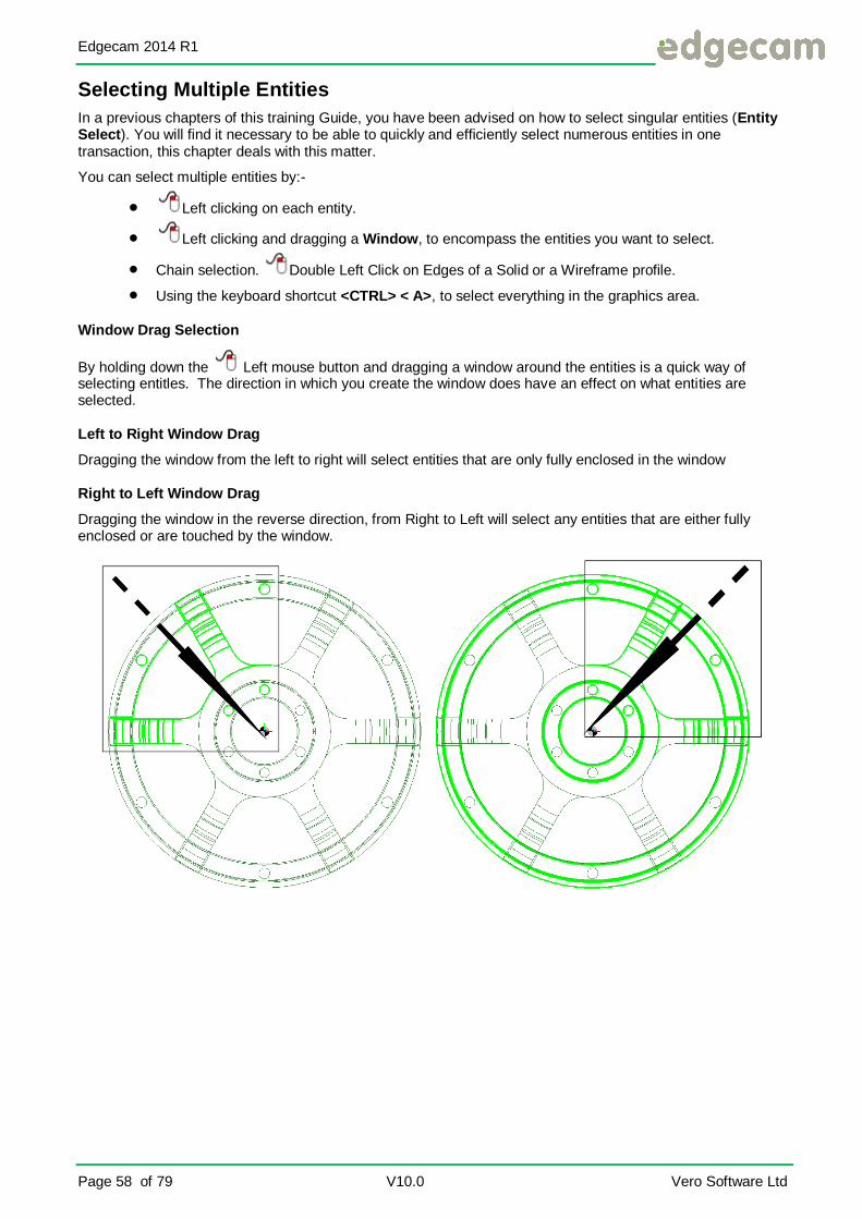
Window Drag Selection
By holding down the Left mouse button and dragging a window around the entities is a quick way of selecting entitles. The direction in which you create the window does have an effect on what entities are selected.
Left to Right Window Drag
Dragging the window from the left to right will select entities that are only fully enclosed in the window
Right to Left Window Drag
Dragging the window in the reverse direction, from Right to Left will select any entities that are either fully enclosed or are touched by the window.

Edgecam 2014 R1
V2014 R1 V10.0 Page 59 of 79
Exercise 8 – Windowing Entities
1. Carry on with the last file or File ►Open the part ’8 - Windowing.ppf’.
2. Select the Top View.
3. Minimise the Component Setup Window if it obstructs your view.
4. Zoom Extents by Double clicking the scroll Wheel.
5. Select the Delete command. Follow the prompt.
Select entity to delete. Left Click at Position A, hold the button down, drag a window over the entire right hand component by moving the mouse down to Position B. Let go of the mouse button. The
two solids are selected. Right Click or Tick to Finish.
6. Select Undo at the top left of Edgcam on the Quick Access toolbar, to bring the solids back.
7. Repeat the Delete command, drag from the same position A but now point B will not fully contain the larger solid.
8. Only the middle solid is selected and deleted.

Edgecam 2014 R1
Page 60 of 79 V10.0 Vero Software Ltd
9. Select Undo .
10. Repeat the above command, except this time drag the window from A to B but from Right to Left.
11. Both Solids will once again be deleted.
Left to Right, everything contained in the window is selected
Right to Left everything contained in the window and everything the window touches is selected
12. Show Only the Wireframe Layer. Repeat the above steps on a wireframe component.

Edgecam 2014 R1
V2014 R1 V10.0 Page 61 of 79
Exercise 9 - Chaining Entities
Edges of a solid model and wireframe profiles can be selected by chaining. With this we Double Left Click on an entity and other adjoining entities will be selected also. We can use chain selection when creating an Edge Loop Feature or picking Edges directly from a solid within a machining cycle. Wireframe entities can also be selected for machining or a containment boundary.
1. File ► Open the file ’9 - Chaining.ppf’.
2. Select Features ► Edge Loop. Fill in the modifiers.
3. Name: Containment Copy from: Edges
4. Select [OK].
5. The Picking Ribbon will now wake up. Ensure that 2D Chain and Tangent Chain are active. It will be highlighted when active.
6. Follow the prompt.
Select or chain-select edges. Double Left Click on one of the Edges at the top of the pocket.
7. All Tangential edges that are on the 2D plane will be selected.
Edgecam 2014 R1
Page 62 of 79 V10.0 Vero Software Ltd
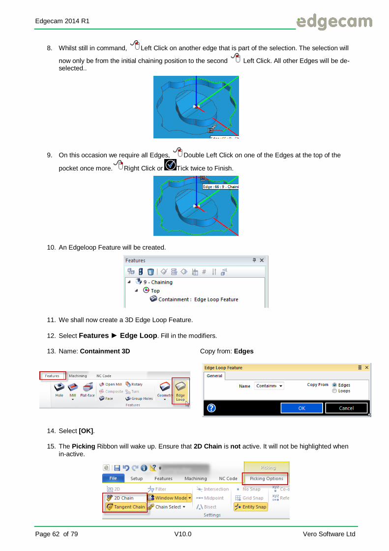
8. Whilst still in command, Left Click on another edge that is part of the selection. The selection will
now only be from the initial chaining position to the second Left Click. All other Edges will be de-selected..
9. On this occasion we require all Edges, Double Left Click on one of the Edges at the top of the
pocket once more. Right Click or Tick twice to Finish.
10. An Edgeloop Feature will be created.
11. We shall now create a 3D Edge Loop Feature.
12. Select Features ► Edge Loop. Fill in the modifiers.
13. Name: Containment 3D Copy from: Edges
14. Select [OK].
15. The Picking Ribbon will wake up. Ensure that 2D Chain is not active. It will not be highlighted when in-active.

Edgecam 2014 R1
V2014 R1 V10.0 Page 63 of 79
16. Follow the prompt.
Select or chain-select edges. Double Left Click on one the Edges at the top of the pocket.
17. All Tangential edges that are on the 3D plane will be selected. Right Click or Tick twice to Finish.
18. A 3D Edgeloop Feature will be created.
An alternative to turning off 2D Chain is to hold down the <CTRL> key at the same time as Double Left Clicking This will toggle between 2D and 3D.
Edgeloop Features may be used for Containment Boundaries in machining cycles or in some cases Geometry to machine.
Edgeloop Features can only be found on a solid model.
19. Show Only the Wireframe Layer.
20. We shall now practise chaining on Wireframe. As Edge Loop Features are only for Solids we need to
use another command. There are a number we could use for example, Offset , Edit Apply To
All ,that we could chain select on. We shall use the Continuous command on this occasion.
A Continuous is a single wireframe entity that contains multiple Lines or Arcs.

Edgecam 2014 R1
Page 64 of 79 V10.0 Vero Software Ltd
21. Right Click in the Layers Window and create a New Layer called Continuous. This will become the active Layer.
22. Select Setup ► Geometry ► Continuous. Leave both modifiers Blank.
23. Select [OK].
24. The Picking Ribbon will wake up. Ensure that 2D Chain is active. It will be highlighted when active.
25. Follow the prompt.
26. Select entities to form continuous (or Finish). Double Left Click on one of the Edges at the top
of the pocket. . Right Click or Tick to Finish.
You cannot de-select the chain in the same way as chaining solid edges.

Edgecam 2014 R1
V2014 R1 V10.0 Page 65 of 79
27. A continuous will be created.
Use theTab Key to show different Entities if required.
You cannot chain Continuous Entities. You must first Explode into their base entities of Lines and Arcs.
28. Save as ’9 – Completed Chaining’.
Edgecam 2014 R1
Page 66 of 79 V10.0 Vero Software Ltd
Keyboard Selection & Entity Types
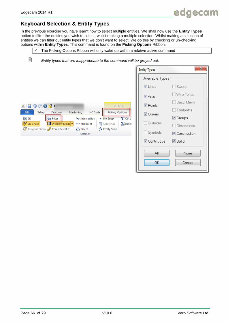
In the previous exercise you have learnt how to select multiple entities. We shall now use the Entity Types option to filter the entities you wish to select, whilst making a multiple selection. Whilst making a selection of entities we can filter out entity types that we don’t want to select. We do this by checking or un-checking options within Entity Types. This command is found on the Picking Options Ribbon.
The Picking Options Ribbon will only wake up within a relative active command
Entity types that are inappropriate to the command will be greyed out.

Edgecam 2014 R1
V2014 R1 V10.0 Page 67 of 79
Exercise 10 - Deleting Entities
The following exercise will show you how to use the Entity Types Filter. On a .dxf for example where many entities are not required. The object of the exercise is to remove all traces of text, including drawing dimensions.
1. Open the file ’10 - Entity Types.ppf’.
2. Select the Setup ► Delete .
3. As we only want to delete certain entity types select Picking Options ► Filter.
4. Select [None] then re-select Dimensions.

Edgecam 2014 R1
Page 68 of 79 V10.0 Vero Software Ltd
5. Select [OK]. Follow the prompt.
Select entity to delete. Hold down the <CTRL> & <A> keys together on your keyboard, then let go.
Edgecam will highlight only the Dimensions and only these will be removed. Right Click or Tick to Finish.
6. Save as ’10 – Completed Entity Types’.

Edgecam 2014 R1
V2014 R1 V10.0 Page 69 of 79
Measuring Distances and Verifying Entities
You can measure the distance between any two points or verify an entity by:
Selecting the Measure icon on the Quick Access Toolbar.
You will be prompted for two positions to Measure between. The information will be shown in the Feedback Window.
Select the Verify icon on the Quick Access Toolbar.
You will be prompted for Entities to verify. The information will be displayed in the Feedback Window.

Edgecam 2014 R1
Page 70 of 79 V10.0 Vero Software Ltd
Solid Machinist
Edgecam Solid Machinist provides the user the ability to load and machine Solid components designed in various parametric CAD packages, without the need for file translation. The Edgecam Solid Machinist license allows the direct loading of native CAD files. This eliminates any possible translation errors that occur when using file translators. Another benefit of using the native solid CAD file is that it has the ability to remain associative to the master model allowing the machining strategies to update when any modifications are made to the solid design.
Supported CAD Formats
The Solid Machinist module is licensed in various ways depending upon the user requirements. The table below details the licensing configurations and the associated file extensions:
Product Code License Description File Formats & Extensions
ENSM0-G Solid Machinist for Granite Pro/Engineer (.prt)
Pro/Desktop (.des)
Creo Parametric
ENSM0-I Solid Machinist for Inventor Autodesk Inventor (.ipt,iam)
ENSM0-C Solid Machinist for CATIA V5 CATIA V5 (.catpart,.catproduct)
ENSM0-A Solid Machinist for ACIS ACIS (.sat, sab)
Spaceclaim (.scdoc)
ENSM0-S Solid Machinist for Parasolid Edgecam Part Modeler (.pmod)
SolidWorks (.sldprt)
SolidEdge (.par)
Step (.stp)
KOMPAS-3D (.a3d, .m3d)
Native Parasolid formats (.x_t, .x_b, .xmt_txt, .xmt_bin)
UGS NX (.prt)
ENSM0-M Solid Machinist Max Combination of ENSM0-I & ENSM0-S

Edgecam 2014 R1
V2014 R1 V10.0 Page 71 of 79
Solid CAD Systems and Edgecam Licenses
The table lists the file formats from the Solid CAD systems and the licences required to load them into Edgecam.
Solid CAD system File types supported Licence required
Autodesk Inventor *.ipt, *.iam Solid Machinist for Inventor or Solid CAD/CAM or Solid Machinist Max
CATIA V5 *.CATpart, *.CATproduct Solid Machinist for CATIA V5
Edgecam Part Modeler *..pmod Solid Machinist for Parasolid or Solid CAD/CAM or Solid Machinist Max
SolidWorks *.prt, *.sldprt, *.sldasm Solid Machinist for Parasolid or Solid CAD/CAM or Solid Machinist Max
Solid Edge *.par Solid Machinist for Parasolid or Solid CAD/CAM or Solid Machinist Max
Pro/DESKTOP, Pro/ENGINEER up to and including Wildfire 5
Creo Parametric
*.prt, *.des, *.pdt, *.g, *.asm Solid Machinist for Granite
UGS NX *.prt Solid Machinist for Parasolid or Solid CAD/CAM or Solid Machinist Max
STEP *.stp Solid Machinist for Parasolid or Solid CAD/CAM or Solid Machinist Max or Edgecam Part Modeler
SpaceClaim *.scdoc Solid Machinist for ACIS or Solid CAD/CAM or Solid Machinist Max or Solid Machinist for CATIA V5
KOMPAS-3D *.a3d, *.m3d Solid Machinist for Parasolid or Solid CAD/CAM or Solid Machinist Max
Native ACIS files *.sat, *.sab Solid Machinist for ACIS or Solid CAD/CAM
Native Parasolid files *.xmb, *.xmt, *.x_t, *.x_b Solid Machinist for Parasolid or Solid CAD/CAM or Solid Machinist Max
IGES files loaded as Parasolid bodies
*.igs Solid Machinist for Parasolid and Part Modeler or Solid CAD/CAM

Edgecam 2014 R1
Page 72 of 79 V10.0 Vero Software Ltd
CAD Integration
This diagram below shows how the various solid CAD packages integrate with Edgecam. Only solid files that are loaded using the Solid Machinist license will have the associative link to the CAD model. Surface files such as IGES are not loaded through the solid machinist interface, and therefore are not associative to the master model.

Edgecam 2014 R1
V2014 R1 V10.0 Page 73 of 79
Installation Notes for Solid Machinist
Solid Machinist Prerequisites (CAD)
Autodesk Inventor
To load an Autodesk Inventor file into Edgecam, one of the following products must be installed on the same PC.
Autodesk Inventor, or Inventor View. A free utility that can be installed from the Autodesk Inventor DVD. Or from the Autodesk website.
If neither product is installed, you see an error message on attempting to load an Autodesk Inventor file into Edgecam.
Edgecam CAD Links
Edgecam CAD Links can be installed by your CAD designer onto their computer. When they save the part for you he automatically saves two files - one is the standard CAD part file the other an .xml file. These two file must remain in the same location
Advantages for Using CAD Links
CAD Links save: Threads, Construction Planes, Coordinate Planes and Sketch Planes.
With all this extra information you will be able to glean more information from the Solid CAD file and machine the part with all the information given by the CAD designer.
Cad Link
Solid Works™, Solid Edge™ and Inventor, all have Cad Link icons. In each of these products, you will find an icon that launches Edgecam directly from the product and, at the same time, loads the part file.
The detection of Solid CAD systems and the installation of the links to Edgecam are achieved by running a separate utility which can be located on the Edgecam Install DVD.
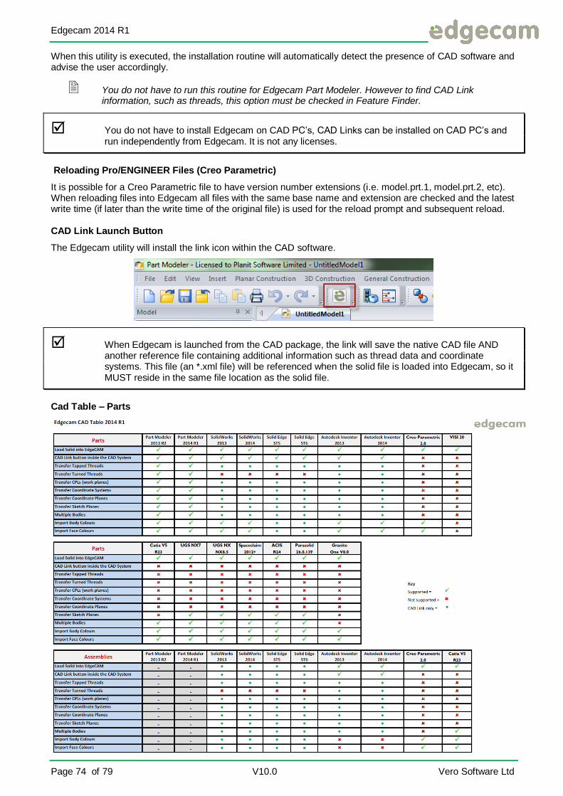
Edgecam 2014 R1
Page 74 of 79 V10.0 Vero Software Ltd
When this utility is executed, the installation routine will automatically detect the presence of CAD software and advise the user accordingly.
You do not have to run this routine for Edgecam Part Modeler. However to find CAD Link information, such as threads, this option must be checked in Feature Finder.
You do not have to install Edgecam on CAD PC’s, CAD Links can be installed on CAD PC’s and run independently from Edgecam. It is not any licenses.
Reloading Pro/ENGINEER Files (Creo Parametric)
It is possible for a Creo Parametric file to have version number extensions (i.e. model.prt.1, model.prt.2, etc). When reloading files into Edgecam all files with the same base name and extension are checked and the latest write time (if later than the write time of the original file) is used for the reload prompt and subsequent reload.
CAD Link Launch Button
The Edgecam utility will install the link icon within the CAD software.
When Edgecam is launched from the CAD package, the link will save the native CAD file AND another reference file containing additional information such as thread data and coordinate systems. This file (an *.xml file) will be referenced when the solid file is loaded into Edgecam, so it MUST reside in the same file location as the solid file.
Cad Table – Parts

Edgecam 2014 R1
V2014 R1 V10.0 Page 75 of 79
Associative Reloading of Solid Part Files
One of the main benefits of using Edgecam Solid Machinist is that the model file remains associative to the CAM instructions. If design changes take place After the component has been manufactured, the machining sequences can be easily updated to reflect the changes.
This method of CAD/CAM integration is achieved using parametric data stored in the solid CAD file. The characteristics of the component and its features are held in a series of unique identifiers for every entity in a body (face, loop, edge and vertex). These unique identifiers are normally referred to as Solid Keys. When a feature is identified, Edgecam holds a cross-reference to the relevant solid key. When a body is reloaded, Edgecam will first try and match the current features to the incoming CAD model. If a match is found, the feature and any associated CAM instructions are automatically updated. New features will be generated for any additional pockets, bosses or holes on the reloaded body.
Reporting Design Changes
Edgecam will detect if a solid part has been modified by the designer. When an alteration is found, Edgecam will acknowledge this fact by displaying the following information message.
The Designer may make an alteration but re-save the file under a different name. This would be the case if a twin component is required that possesses subtle design changes.
In this instance, Edgecam will not automatically inform the user. The user must manually re-load the revised
solid part by Right Clicking on the Solid model in the Features Window.
Best Practices for CAD Designs
It is important to fully understand and realise that the method employed to modify the solid design can affect the way features are updated in Edgecam. For example, if a pocket in a body is moved, stretched or edited this will generally result in an updated feature because the cross-reference is maintained. However, if a pocket is deleted and a new pocket placed in the same area, the cross-reference maybe lost, as the pocket will not contain the same unique identification as the initial pocket, although the Solid Machinist engine may decide that the new feature is a Best Match to the original design and apply the machining instructions to the new feature.
It is advisable wherever possible to parametrically modify solid CAD files as this ensures greater integration with CAM instructions.
Advise your designers that you are using the solid models for manufacturing, and that the resulting CAM data is linked to the master model.

Edgecam 2014 R1
Page 76 of 79 V10.0 Vero Software Ltd
Leaving Edgecam
Once you have finished working with Edgecam, you must exit the system and return to the Windows desktop. To exit Edgecam select the cross in the top right hand corner.
Complete and save your work if required
Edgecam warns you that you have not saved your work if you try to leave Edgecam without saving. Select [Yes] to save any changes before leaving Edgecam, or [No] to exit without saving the changes.
Getting Further Help
This training guide is designed to help you become familiar with Edgecam, introducing you to the concepts and skills you need to design and machine different types of component.
You can refer to the following sources of information for further help on any aspect of Edgecam that is not covered in this training guide:
Edgecam on-line help.
Edgecam 2014 R1
V2014 R1 V10.0 Page 77 of 79
Index
A
Angular ............................................................................. 40 Angular co-ordinates ....................................................... 40 Arc ..................................................................................... 42 Associative ....................................................................... 75 Autodesk Inventor ....................................................... 70, 73 Autosave ............................................................... 30, 31, 32
B
Buttons ............................................................................. 29
C
CAD ............................................. 9, 70, 71, 72, 73, 74, 75, 79 Cartesian .......................................................................... 40 Cartesian co-ordinates .................................................... 40 CATIA ............................................................................... 70 Chaining ........................................................................... 61 Changing .......................................................................... 30 CNC code........................................................................... 9 Colour .......................................................................... 39, 52 Configure ........................................................................... 34 Configuring ....................................................................... 30 Continuous ....................................................................... 39 Continuous entities .......................................................... 39 Co-ordinates ............................................................... 40, 45 CPL.............................................................................. 34, 42 Creating ....................................................................... 32, 55 Cursor............................................................................... 33 Curves .............................................................................. 39
D
data ..................................................................................... 6 Data ....................................................................... 28, 61, 62 Defaults ................................................................. 31, 32, 37 Defined ............................................................................. 32 Deleting ............................................................................ 67 Design ..................................................................... 9, 39, 75 Dimensions ........................................................................ 68 DXF files ........................................................................... 30
E
Edgecam . 2, 6, 9, 10, 11, 12, 13, 14, 15, 16, 17, 18, 24, 28, 29, 31, 32, 35, 37, 39, 40, 43, 45, 47, 52, 53, 57, 68, 70, 71, 72, 73, 74, 75, 76, 79
Edgecam Part Modeler................................... 14, 15, 70, 74 Edgecam Solid Machinist ........................................... 70, 75 Entities ............................................ 39, 53, 58, 59, 61, 67, 69 Entity ....................................33, 39, 42, 43, 58, 61, 62, 66, 67 Entity Digitise .................................................. 39, 42, 43, 58 Entity types ...................................................................... 66 Environment .................................................... 30, 31, 32, 76 example .............................................................................. 7 Example ............................................................................. 6
F
Feature ........................................................................ 25, 74
G
Geometry ............................................... 41, 42, 45, 56, 61, 62
H
Horizontal ......................................................................... 41
I
in Edgecam ........................................................................ 6 Intellisnap ............................................................... 50, 52, 53
J
Job .................................................................................... 14
L
Layer...................................................................... 39, 55, 57 Layers .................................................................... 55, 56, 57 Line ........................................................ 41, 42, 45, 56, 61, 62
M
Menus ............................................................................... 29 Mouse wheel sensitivity................................................... 30
N
New feature ...................................................................... 75
O
Opening ............................................................................. 16
P
part ................................................................................. 2, 6 Part ........................................ 6, 14, 15, 31, 32, 45, 70, 74, 75 Part Modeler ................................................... 14, 15, 70, 74 Points ............................................................................... 39 Polar ................................................................................. 40 Pro/ENGINEER ............................................................... 74 Properties .......................................................................... 34
S
Selecting ......................................................... 30, 37, 47, 58 Setting ................................................................... 30, 31, 34 Solid........................................... 25, 37, 53, 70, 71, 72, 73, 75 Solid Machinist ................................................ 70, 72, 73, 75 SolidWorks ....................................................................... 70 Splitting............................................................................. 30 standard ............................................................................. 6 Status bar ......................................................................... 30 Strategy ............................................................................ 25 Surface ............................................................................. 72 Surfaces ........................................................................... 39
T
text ...................................................................................... 7 Text ..................................................................................... 7

Edgecam 2014 R1
Page 78 of 79 V10.0 Vero Software Ltd
Time ................................................................................... 16 Tolerance ......................................................................... 25 Tool ............................................................................. 33, 43 Toolchange......................................................................... 33 Toolpaths .......................................................................... 39 Types .......................................................................... 66, 67
V
Verifying............................................................................ 69
W
windows .............................................................................. 6 Windows .................................................................. 2, 16, 76 Wire .................................................................................. 16

Edgecam 2014 R1
V2014 R1 V10.0 Page 79 of 79
Document Revision Control
Rev.1-3 - Various Updates.
Rev.4.0 - Updated for Edgecam V2009 R1 01 December 2008
Rev.5.0 - Updated for Edgecam V2009 R2 April 2009
Rev.5.1 - New Edgecam Logos Added June 2009
Rev.5.2 - Front Page, Copyright and Index Added July 2009
Rev.6.0 - Updated for V2010 R1 October 2009. Screen Shots updated for CAD package versions page 74, 76, 77. Minor issues, left and right icons for mouse button clicks added in various areas. Some grammar to suit. Modified by SBL.
Rev.7.0 – July 2010 Updated for V2010 R2. New Vero Template. Exercises 1 & 2 re-written to take into account new functionality File locations added. Minor changes elsewhere. SBL.
Rev.7.1 – August 2010. Minor Grammar changes throughout and renumbering corrected. SBL.
Rev.8.0 – December 2010. Updated for V2011 R1. Minor Grammar changes throughout. All screen shots updated to suit new colour scheme. No new exercises. SBL.
Rev 9.0 - November 2011 Updated for V2012R1.Screen shots only, no new exercises. AWA. SBL.
Rev 9.1 – August 2012 New template, Digitise, Planit and Front page removed. SBL.
Rev 10.0 – Feb 2014. New Template. Updated for 2014 R1. Too many changes to list. SBL.