what’s new in - vero softwaredownloads.verosoftware.com/edgecam/2017r1/ec2017r1_whatsnew… ·...
TRANSCRIPT
What’s New in Edgecam 2017 R1
This document highlights new product features and enhancements in Edgecam 2017 R1.
To run Edgecam and Part Modeler 2017 R1, the expiry date in the license must be October 2016 or later.

www.edgecam.com
What's New in Edgecam 2017 R1 2 of 69
Contents
‘WHAT’S NEW’ DOCUMENT OVERVIEW .................................................................................................................. 4
IMPORTANT INFORMATION .................................................................................................................................... 5
Manufacture Enhancements
TOMBSTONE ........................................................................................................................................................... 6
INTELLIGENT COLLISION AND FIXTURE AVOIDANCE FOR CLEARANCE AND LINK MOVEMENTS (INDEXING) .................................. 6
INSERT COMPONENT IMPROVEMENTS .......................................................................................................................... 7
ALLOW CPL TYPE TO BE SPECIFIED .............................................................................................................................. 7
ROUGHING FROM CURRENT STOCK ADJUSTS CYCLE LEVEL TO STOCK HIGH POINT ABOVE SELECTED FEATURE ............................... 8
PROFILING - CUT INCREMENT STAND OFF ADDED TO LINKS TAB ........................................................................................ 8
PROFILING - SUPPRESS HELICAL CLEAN UP PASS ADDED TO DEPTH TAB .............................................................................. 9
PROFILING - CUT BY OFFSET OPTION ADDED TO MULTIPLE PASSES SECTION OF GENERAL TAB ................................................. 9
PROFILING CYCLE - BREAK CORNERS OPTIONS WITH GEOMETRY COMPENSATION ............................................................... 10
PROBING FOR TURNING .......................................................................................................................................... 10
INTERPOLATE ANGLE / DISTANCE ON FIVE AXIS............................................................................................................ 11
ROUGH GROOVING CANNED CYCLE ........................................................................................................................... 12
SELECTING CHUCKS FOR SUB SPINDLE ........................................................................................................................ 13
WIRE TRANSFORMATIONS ....................................................................................................................................... 14
WIRE WIREFRAME FEATURES ................................................................................................................................... 15
WIRE - FANUC TECHNOLOGY DATABASE ADDED FOR FANUC Α-C600IA ........................................................................... 15
ADVANCED SUB PROGRAMMING CAPABILITIES IN WIRE ................................................................................................. 16
SAFE RETRACT ENABLED IN TURNING ......................................................................................................................... 17
AUTO STOCK FROM MODEL ..................................................................................................................................... 17
FILTER CPLS ......................................................................................................................................................... 18
STORE TOOLPATH GRAPHICS DATA............................................................................................................................ 18
WORKFLOW SHIPPED STRATEGIES IMPROVEMENTS ...................................................................................................... 19
Interface Enhancements
SESSION DETAILS ADDED TO SETUP BROWSER .............................................................................................................. 20
IMAGES ON DIALOGS (TURNING CYCLES) .................................................................................................................... 21
ROTATIONAL HANDLE ON DYNAMIC CPL MARKER WITHIN THE TURNING ENVIRONMENT .................................................... 23

www.edgecam.com
What's New in Edgecam 2017 R1 3 of 69
Simulator Enhancements
VIEW COMPARISON FOR MULTIPLE COMPONENTS ........................................................................................................ 24
Edgecam Workflow Solids
ISOMETRIC VIEW SHOWN WHEN EXTRUDING / REVOLVING FIRST SKETCH.......................................................................... 25
Code Wizard Enhancements
COMMAND LINE IMPROVEMENTS .............................................................................................................................. 26
SUPPORT FOR POLAR INTERPOLATION OPTIONS IN AXIAL ROTARY MILLING ....................................................................... 26
AXIAL ROTARY MILLING PARAMETERS RENAMED .......................................................................................................... 26
LINEAR TURRET SUPPORT ........................................................................................................................................ 27
SUPPORT FOR SLIDING SPINDLES / SLIDING MATERIAL .................................................................................................. 28
SUPPORT FOR X MOVEMENT ON MOVE SUB SPINDLE COMMAND .................................................................................... 28
NEW VARIABLES FOR CANNED ROUGH GROOVE CYCLE ................................................................................................. 29
INDEXG200 TEMPLATE USING VARIABLE ADDRESSES .................................................................................................... 30
LOWER TURRET CONTROL OVER COOLANT M-CODES .................................................................................................... 31
PROBING FOR TURNING .......................................................................................................................................... 31
NEW LANGUAGE TRANSLATION MECHANISM FOR POST PROCESSORS ............................................................................... 32
Code Generator Enhancements
VARIABLE FORMATTING .......................................................................................................................................... 33
NEW SYSTEM VARIABLES FOR CANNED ROUGH GROOVE CYCLE ...................................................................................... 33
NEW SYSTEM VARIABLES FOR REFERENCING DATUMS.................................................................................................... 33
Miscellaneous Enhancements
NEW PCI COMMANDS TO HANDLE LAYERS ................................................................................................................. 34
RPM DIAMETER ADDED TO TURNING TOOL ................................................................................................................ 35
Licensing
CLS NETWORK LICENSING PROFILES .......................................................................................................................... 36
LICENSE MANAGER DIALOG ..................................................................................................................................... 36
NEW MODULE LICENSE - EDGECAM TOMBSTONE MANAGER ......................................................................................... 36
MAINTENANCE DATABASE REPORT....................................................................................................................... 37
NEW FEATURES IN VERSION 2016 R2 .................................................................................................................... 38

www.edgecam.com
What's New in Edgecam 2017 R1 4 of 69
‘What’s New’ Document Overview
Purpose of this Document and Other Sources of Information
The purpose of the document is to highlight new and changed items in the current release. Non-release specific information such as installation and licensing information, system requirements and CAD Links information can be found in the relevant document.
For help with your installation, please refer to the Installation Guide. This is available from the DVD or the Help sub-menu in the Edgecam program group.
For help with licensing your standalone or network license, please refer to the Licensing Guide. This is available from the Help sub-menu in the Edgecam program group, the CLS menu and the License Manager dialog.
For information on system requirements and supported CAD systems, please refer to the Installation Guide.
Targeted Information inside Edgecam and Other Programs
In addition to this document, ‘targeted’ information on new items is available in the dialog help and user guides for other applications. This allows you to focus on new features/enhancements for a specific program or the cycle you are currently working on, for example.
Dialogs that have new functionality or where the cycle behaviour has changed have an additional ‘What’s New’ tab in the help. This explains what has been added to the dialog or changed in this release.
What’s new topic(s) have been added to help files for other programs, such as Code Wizard, Code Generator, and ToolStore etc. This only lists new functionality for that program, allowing you to focus on those items.
The Development History of Edgecam
Additional functionality and enhancements are developed with each release of Edgecam software. For an overview of new features and enhancements in the last release, please refer to New Features in Version 2016 R2.
For a summary of new features in previous releases, please visit the History section of the Edgecam website.

www.edgecam.com
What's New in Edgecam 2017 R1 5 of 69
Important Information
Windows 8 no longer supported
Support for Windows 8 has been removed from this release onwards.
Windows 8.1 will continue to be supported.
CATIA V4 Loader will be unsupported at this release
The CATIA V4 Loader has been frozen for some time and unsupported from the third party supplier. The issue is that on Windows 8.1 and Windows 10 the application will crash due to tighter UAC controls. We are still shipping the Loader and it does still work on Windows 7.
We expect to remove support at Edgecam 2017 R2.
Internet Explorer 11 is required
Due to new functionality in Edgecam 2017 R1, Internet Explorer 11 is required.
Note: Edgecam 2016 R2 required Internet Explorer 10.
License Expiry Date
To run Edgecam 2017 R1, the maintenance expiry date in your license must be October 2016 or later.
Installing Edgecam 2016 R2 after 2017 R1
If Edgecam 2016 R2 is installed after Edgecam 2017 R1, Internet Explorer 8 is set to be used and will cause problems with the browsers in 2017 R1 which use Internet Explorer 11.
The solution is to reinstall Edgecam 2017 R1.

www.edgecam.com
What's New in Edgecam 2017 R1 6 of 69
Manufacture Enhancements
Tombstone
For this release, we have introduced a Tombstone module for assembly of pre-existing parts on a defined mounting device allowing further optimisation and subsequent simulation and output.
Note: Tombstone is a licensed module and customers will not see the new Tombstone manager unless the module is purchased / added to their license.
Intelligent Collision and Fixture Avoidance for Clearance and Link
Movements (Indexing)
In previous releases, the user had to specify a clearance radius which was used whenever the tool was indexed.
For this release, a new Collision Check Index Moves option has been added which, when checked, will optimise the clearance / retract distance automatically.
Note: For old parts the option is off, by default.

www.edgecam.com
What's New in Edgecam 2017 R1 7 of 69
Insert Component Improvements
It is now possible to insert separate sequences from a recently saved PPF.
There are new Sequence Source List and CPL Source List options on the dialog:
Using Sequence Source List, you can either import all sequences or a separate sequence, identified by its name. This is unavailable until Insert Sequences is checked.
In CPL Source, there is now a List option to choose from the list of available CPLs in the PPF (CPL Source List).
Note: To insert an old PPF, the file needs to be opened and saved in the current version.
Allow CPL Type to be specified
A CPL Type option has been added to the General tab of the Create and Edit CPL dialogs which allows you to select one of the following CPL types:
Default.
Mating Location.
Machine Datum.

www.edgecam.com
What's New in Edgecam 2017 R1 8 of 69
Roughing from Current Stock adjusts cycle level to stock high point
above selected feature
With Stock Type of Current Stock, the cycle level is now automatically adjusted to the level of the current stock high point directly above the selected feature.
Notes:
1. The stock must be updated prior to applying the cycle otherwise additional unwanted passes may be generated.
2. If unwanted polishing cuts are generated, specifying a small negative stock offset should remove them.
Profiling - Cut Increment Stand Off added to Links tab
A new Cut Increment Stand Off field has been added to the Links tab of the Profile Milling cycle. This allows you to control the rapid approach height above the previous depth of cut from which to start feeding down to the next cut level.
When specified, the tool will feed from (last cut depth + Cut Increment Stand Off) down to the next depth of cut.
The Cut Increment Stand Off will be overridden if:
Feed When Plunging is checked.
Apply Safe Distance on the Lead Tab is checked.

www.edgecam.com
What's New in Edgecam 2017 R1 9 of 69
Profiling - Suppress Helical Clean Up Pass added to Depth tab
A new Suppress Helical Clean Up Pass option has been added to the Depth tab of the Profile Milling cycle for circumstances where this is not required.
By default the clean up pass is made; existing parts are unaffected.
Profiling - Cut by Offset option added to Multiple Passes section of
General tab
A Cut by Offset option has been added to the Multiple Passes section on the General tab of the Profile Milling cycle:
When checked, all Z cuts are completed for a set of offset passes before moving to the next set of offset passes.
When unchecked, all passes are completed at one level before moving down to the next level.

www.edgecam.com
What's New in Edgecam 2017 R1 10 of 69
Profiling Cycle - Break Corners options with Geometry Compensation
Previously, when Geometry compensation was in use, users were limited to the Sharp and Round corner strategies in the Profiling cycle. To enhance the capabilities of the cycle, we have now added more corner strategies:
Notes:
1. When compensation is being used, the High Speed and Sharp corner strategies will produce the same NC Code as the Round strategy if the back offset is identical. In the machine, Sharp and High Speed are probably not applicable; a Feedback message has been added to these cases to warn the user.
2. For the Twizzle corner strategy, it is important that the generated NC Code is tested in the machine first. Some controllers might encounter problems with the toolpath crossing itself.
Probing for Turning
For this release, we have implemented Probing for Turning.
Note: Probing requires a standard turning license or above so that it can be loaded as a driven tool.
This involves enhancements to Edgecam, Code Wizard and the post-processor template:
Edgecam
In Toolchange:
A probing tool can be loaded on all turrets. The tool can also be loaded in any orientation with the CPL (datum) being orientated accordingly.
The Probing category in ToolStore is only accessible via Toolchange.
Probing cycles can only be created if a probing tool is selected, the mode is Planar and probing macros are available in the current post.

www.edgecam.com
What's New in Edgecam 2017 R1 11 of 69
Interpolate Angle / Distance on Five Axis
2016 R2 and 2017 R1 code (using Max Angle of 5 deg):
Edgecam now follows the Interpolate settings (Angle and Distance) for the approach moves of a Five Axis cycle.
Current cycles using these settings will, therefore, show a significant change in the output when generating code.
Notes:
1. If Interpolate Distance is set but Max Distance is blank, a default of 1mm (0.05 inches) is set for rapid and feed moves.
2. If Interpolate Angle is set but Max Angle is blank, defaults of 10 deg for rapid and 3 deg for feed moves are set.

www.edgecam.com
What's New in Edgecam 2017 R1 12 of 69
Rough Grooving Canned Cycle
A Canned Cycle capability has been added to the Rough Grooving cycle, broadly following the principles of Straight Turn and producing a G75 type cycle in the NC. This has involved the following enhancements:
Edgecam
A Canned Cycle checkbox is available on the General tab of the Rough Grooving cycle dialog as long as the code generator selected has the ability to output in this form.
Note that when canned cycles are output to the NC code, the toolpath is machine dependent and simulation may not be an exact match. If Canned Cycle is selected some other options will no longer be valid. The groove is checked for suitability including corner radii compared with tool corners and a cylindrical (not conical) groove base.
Code Wizard
Three variables have been added to the Turning Cycles G-Codes tab:
Rough Groove canned cycle support ?.
Rough Groove Output Zero Peck Depth.
Rough Groove.
Code constructors for the cycle (with lower turret variant where applicable) have been added with appropriate tokens. For ISO style machines, a sample output format has been created which can be modified to suit individual requirements. For Siemens machines, the code constructor does not have sample output but the full range of relevant tokens is available.
Code Generator
Four new system variables (PECKRETRACT, STEP, XEND2 and ZEND2) have been added to Turning MACRO 6 (ROUGH GROOVE CYCLE) to implement this functionality.
Notes:
1. This cycle generates RAPID approach moves to the selected cycle start point from which position the canned cycle will be activated, finishing at the cycle end point XEND2, ZEND2.
2. The implementation is for grooves in the part diameter only. Face grooves are not currently included.

www.edgecam.com
What's New in Edgecam 2017 R1 13 of 69
Selecting chucks for Sub Spindle
When selecting fixtures using Fixture Manager, you can now place a chuck on the opposite side of the component. This enables the Sub Spindle to have a custom chuck as was already possible for the Main Spindle.
When selecting a Chuck with Jaws or Chuck Collet, the Chuck or Collet can be placed on the opposite side by selecting Sub Spindle.

www.edgecam.com
What's New in Edgecam 2017 R1 14 of 69
Wire Transformations
Rotate Wire and Mirror Wire commands have been added to the Wire Ribbon Interface allowing single or multiple wire instructions to be transformed:
From and To labels group the instructions to be transformed.
For Rotate Wire, specify the Angle and set the Centre of Rotation.
For Mirror Wire, define the mirror line about which to Mirror.
Mirrored toolpaths are not subroutined.
Subroutine output is supported for Translate Wire and Rotate Wire.
It is possible to apply multiple transformations but nested subroutines are not supported in these situations.
The strategy defined in Wire Setup is upheld for the transformations; for example, when set to Unattended night run (pockets), all repetitions are machined before returning to cut all of the tags.
www.edgecam.com
What's New in Edgecam 2017 R1 15 of 69
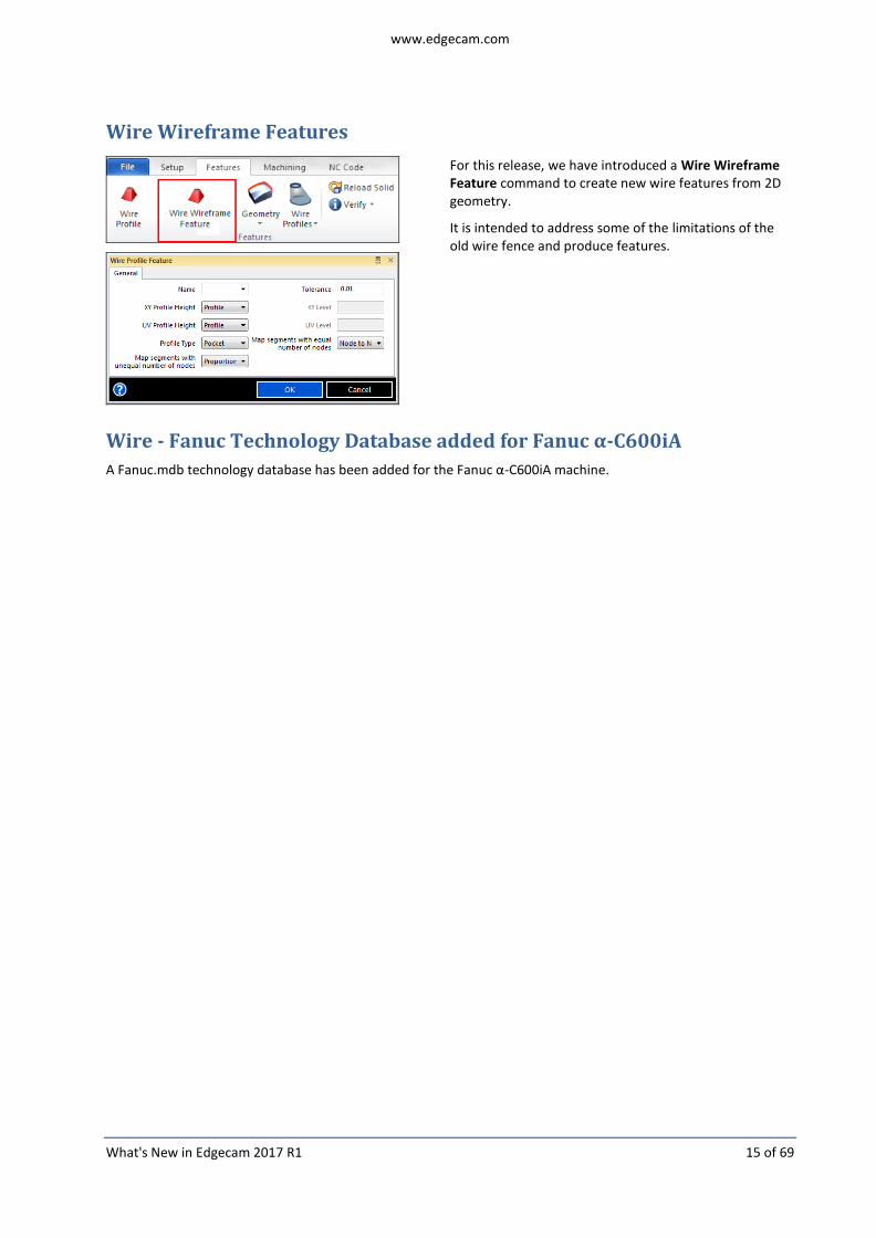
Wire Wireframe Features
For this release, we have introduced a Wire Wireframe Feature command to create new wire features from 2D geometry.
It is intended to address some of the limitations of the old wire fence and produce features.
Wire - Fanuc Technology Database added for Fanuc α-C600iA
A Fanuc.mdb technology database has been added for the Fanuc α-C600iA machine.

www.edgecam.com
What's New in Edgecam 2017 R1 16 of 69
Advanced Sub Programming capabilities in Wire
For this release, advanced sub programming options have been added to the Output Options in Wire.
To output code using sub programs, the user can select one of the following options:
None.
Features - each feature will generate a sub program.
Setups - each Wire Setup will generate a sub program.
Cuts - each offset will generate a sub program.
Operations - each cycle will generate a sub program.
These sub program options have been added to the following posts:
ACcut
AccuteX
ACfanuc
ACmillennium
Brother
Chmer
Excetek
Fanuc
Hitachi
Joemars
Makino
Mitsubishi
Ona
Sodick
Notes:
1. To avoid problems with old parts, all post-processors will have the Sub Program Output option set to None by default.
2. ACcut and Sodick do not have the Cuts option.

www.edgecam.com
What's New in Edgecam 2017 R1 17 of 69
Safe Retract enabled in Turning
The Force Rapid to Toolchange and Force Rapid to Home preferences on the Toolpaths tab are now available in the Turning environment.
Auto Stock from Model
A new Auto Stock from Model option has been added to the Preferences.
This can be used to automatically create stock from the solid models when there is no stock defined. Typically, this would be used when there is no real stock requirement or when you only want to check if the machining itself runs correctly on simulation.
When this is enabled, if you attempt to simulate a Mill or Turn part and no stock has been defined, Edgecam will make a copy of the models (solids present on the part) and convert them into stock. Simulator will then have a component and a stock representation.
Note that this will have no effect if there is no solid model present on the part or when stock already exists.

www.edgecam.com
What's New in Edgecam 2017 R1 18 of 69
Filter CPLs
A new Filter CPLs option has been added to the Preferences.
When this is enabled, commands that list CPLs for selection, such as sequence setup and indexing, will filter for the appropriate CPL type. CPL type can be defined when creating the CPL as one of the following:
Default - no specific type.
Datum - used for indexing.
Location - used for mating.
If a CPL is not being shown for a command, disabling this option will remove the filtering and list all CPLs.
Store Toolpath Graphics Data
A new Store Toolpath Graphics Data option has been added to the Preferences.
When this is enabled, different parts of the graphics can be turned on and off before being saved.
This is useful when a user creates too much toolpath or believes that a toolpath is not important and, therefore, wishes to remove it.

www.edgecam.com
What's New in Edgecam 2017 R1 19 of 69
Workflow Shipped Strategies Improvements
As part of the ongoing improvements to the Workflow Shipped Strategies, the following enhancements have been implemented:
Support Sub Spindle
Previously, the Shipped Strategies did not prevent the user from applying strategies to the Sub Spindle or to the Main Spindle when there was a part. However, the part was not transferred from the Main Spindle to the Sub Spindle. When a sequence is created and there are features on the Main and Sub Spindle, strategies will be assigned to them and selecting Apply will machine all features in the Main Spindle, transfer the part to the Sub Spindle and finish machining it.
Support Ream Strategy
The ability to finish holes with Ream strategy has been added. The user needs to set Hole Finish Method to Ream and the Maximum Reamer value in order to filter bigger holes.
Safe Index for Milling
In previous releases, the tool would be moved to toolchange in order to ensure that it was safe. The Shipped Strategies now use the Collision Check Index Moves option from Update Fixture and apply a safe index which is safer and quicker.
Note: For Older parts (2016 R2 or earlier), the Update Fixtures command must be manually edited and an Offset entered. Otherwise, a toolpath with collisions may be created.
Machine Feature to Use Current Tool
The Machine Feature option is used to apply a quick toolpath for a specific feature; either roughing, finishing or both. For this release, we have added the ability to Use Current Tool which will ignore the tooling selection from the Shipped Strategies and use the last tool in the machining sequence.
This improvement should provide quicker toolpath generation which can be edited later, if required.

www.edgecam.com
What's New in Edgecam 2017 R1 20 of 69
Interface Enhancements
Session details added to Setup Browser
For this release, the Setup Browser has been split into Session and Setup areas and the Environment, Machine Type and Material details have been moved to the Session window:
When you load a solid model, the Session area allows the user to change the Environment (Milling or Turning) and the Material.
The Setup area allows the user to set the Information, Position Datum and Position for each Component.
The Component is the solid, stock and fixture for specific machining. The user may have two different solids, stock and fixture that will be machined in the same sequence or in different sequences but in the same session.
Each Component now has its own CPL and, instead of moving the whole part / stock / fixture around every time the user changes the datum and position, this CPL will be moved around. Therefore, if Auto Align sets the TOP CPL to be in the upper corner of the solid and the user starts moving the part, the TOP CPL does not move.
Previously, everything moved together but now, each Component can now be moved independently. This means that the user can now use the interface instead of the other Transform commands.
www.edgecam.com
What's New in Edgecam 2017 R1 21 of 69
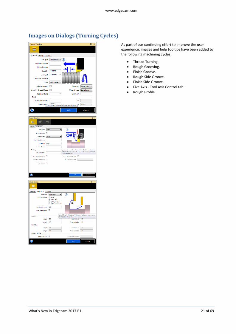
Images on Dialogs (Turning Cycles)
As part of our continuing effort to improve the user experience, images and help tooltips have been added to the following machining cycles:
Thread Turning.
Rough Grooving.
Finish Groove.
Rough Side Groove.
Finish Side Groove.
Five Axis - Tool Axis Control tab.
Rough Profile.

www.edgecam.com
What's New in Edgecam 2017 R1 22 of 69

www.edgecam.com
What's New in Edgecam 2017 R1 23 of 69
Rotational Handle on Dynamic CPL Marker within the Turning
Environment
To improve the user experience we have implemented a rotation handle on the CPL marker within the Turning environment which will allow users to manipulate the X axis position relative to the Z axis. The new handle will:
Allow viewing of the part. The part can be revolved from the CPL marker by moving the cursor over the handle until it turns yellow and then holding the mouse button down and moving the mouse around.
Allow users to manipulate the rotational position of the X axis when defining CPL's to find features.
Allow users to define a C0 position for machining.

www.edgecam.com
What's New in Edgecam 2017 R1 24 of 69
Simulator Enhancements
View Comparison for multiple components
The View Comparison function has been enhanced to support analyses of a selected component inside Simulator.
Previously, if more than one component (model + stock) was available, Simulator would simply compare the first element defined and not give any opportunity for the user to check other components from the same session.
The enhancements implemented for Component Setup have introduced the concept of multiple and well defined structures when more than one part and stock is in the same section. This new structure has allowed Simulator to implement component selection when doing a comparison.
Notes:
In Turning, the existing structure for component already allowed a clear definition of Main Spindle component and Sub Spindle components. That structure is now used and, when View Comparison is requested in Simulator, the user will be prompted to select a stock; no selection of model is required, as this is already known.
In Milling, the functionality is completely dependent on a well defined setup structure. If that structure is undefined or incorrectly defined, comparison will use the previous behaviour and compare the first component only.

www.edgecam.com
What's New in Edgecam 2017 R1 25 of 69
Edgecam Workflow Solids
Isometric View shown when Extruding / Revolving First sketch
Isometric orientation when Extruding the FIRST sketch.
Isometric orientation when Revolving the FIRST sketch.

www.edgecam.com
What's New in Edgecam 2017 R1 26 of 69
Code Wizard Enhancements
Command Line improvements
A new Command Line options is now available:
Parameter Function Notes
-q -quiet Prevent the display of the UI during template compilation.
Support for Polar Interpolation options in Axial Rotary Milling
Axial rotary milling on Mill and MTM machines enables the user to perform machining using the rotary table as the secondary axis.
In previous releases, output was limited to a 'True Polar' scenario consisting of an Angle and a Polar Radius and the user could select the active axis and side resulting in the following typical outputs:
X+ C
X- C
Y+ C
Y- C
For Lathe machines, the 'Fanuc Polar' output method can be used which consists of a Cartesian output which the machine understands and executes (in rotary) accordingly. In Fanuc based controllers that mode is normally enabled by G12.1 or G12 or G112 and disabled by G13.1 or G13 or G113.
Support for this output method has now been included on the Milling / MTM templates similar to that found in CY applications.
Axial Rotary Milling parameters renamed
For this release, two machine parameters have been renamed to clarify their purpose:
Cartesian output in Rotary Milling to Force Planar in Rotary Axial Milling.
Cartesian output in Rotary Holes to Force Planar in Rotary Axial Holes.

www.edgecam.com
What's New in Edgecam 2017 R1 27 of 69
Linear Turret Support
For this release, Linear Turret support has been introduced in Edgecam with modifications to the Turret tab in Machine Configuration:
Linear option added to the Type modifier.
Offset for first position, Mount Axis and Pitch Linear turret Parameters.
Tools are mounted in a linear fashion, in a specified direction. This arrangement is mainly used on swiss type machines but also in other normal configurations.
Note: Turrets and tools still need to point towards the job, either axially, radially or at an angle. The following situations are supported:
Turret for radially mounted tools or radial mounting blocks.
Turret for axially mounted tools or axial mounting blocks.
Left turrets facing main and right turrets facing sub spindle.

www.edgecam.com
What's New in Edgecam 2017 R1 28 of 69
Turrets facing the Y axis are supported using the slant functionality.
Support for Sliding Spindles / Sliding Material
Continuing with supporting advanced machine configurations, we now support turning machines with Sliding spindles.
The main difference on these machines is that a Z axis from the turret can be placed on the spindle, making it move in Z instead. The implementation is based on Simulator changes which enable it to identify the available Z Axis (turret or spindle) and simulate the sequence accordingly.
Support for X movement on Move Sub Spindle command
Support for machines that have the sub-spindle dislocated (in X) was implemented previously using the new Spindle Setups.
However, the user may not want to create a new setup, but simply move the sub-spindle, with or without the part. In this situation, moving in X might also be required.
Therefore, the Move Sub Spindle command now allows for X movement The dialog has not changed but now it allows for X input when creating or re-selecting the sub-spindle position.
A typical scenario would be when some work is done on main spindle and, for accessibility reasons, the part is moved with the sub-spindle into an intermediate position to allow further work to be done.
The sub-spindle moves follow two basic rules:
When moving towards the Main Spindle, X moves first.
When moving away from Main Spindle, Z moves first.
www.edgecam.com
What's New in Edgecam 2017 R1 29 of 69
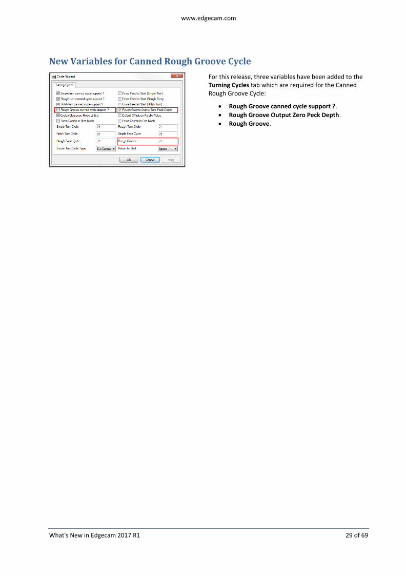
New Variables for Canned Rough Groove Cycle
For this release, three variables have been added to the Turning Cycles tab which are required for the Canned Rough Groove Cycle:
Rough Groove canned cycle support ?.
Rough Groove Output Zero Peck Depth.
Rough Groove.

www.edgecam.com
What's New in Edgecam 2017 R1 30 of 69
IndexG200 Template using Variable Addresses
The CY output for the IndexG200 template has been changed to use the variable formats which simplifies the code because the template is now standard. In addition, some of the redundant variables have been removed to make the post-processing simpler.
Changes have been implemented in the token definitions, code constructors content and the process of setting the format for each of the CY variables being output.
Tokens Definition
We have changed a number of tokens which means that rather than having a single and fixed format, it will change depending on which turret or spindle is active. These changes will be seen in the Format Table.
These addresses are configurable through menus in NC Style tab.
Code Constructors:
Some of the CY tokens have been changed. The blue highlight for these tokens means that the format is a variable address.

www.edgecam.com
What's New in Edgecam 2017 R1 31 of 69
Lower Turret control over Coolant M-Codes
For this release, new coolant controls have been introduced. When Turret Control Over M-Codes is checked:
The new M-Codes for Coolant Mist, Coolant Flood, Air Coolant On and Coolant Off will override the main coolant M-codes when it is a Lower Turret operation.
The sub-spindle M-Code will not have an effect on the output code because the Turret now controls the coolant codes.
Probing for Turning
For this release, we have implemented Probing for Turning.
Note: Probing requires a standard turning license or above so that it can be loaded as a driven tool.
This involves enhancements to Edgecam, Code Wizard and the post-processor template:
Code Wizard
Renishaw Probing and m&h Probing can be selected on the Machine Configuration dialog:
Probing is only available if C&Y Axis is selected.
Renishaw Probing is a licensed option.
Probing is disabled if Siemens based templates are selected. IndexG200 also does not have Probing.
You can add Probing to existing posts or change between m&h and Renishaw using the Add Device option.
Post-Processor Templates
After selecting either Renishaw Probing or m&h Probing functionality, the Format Table, NC Style tab and additional Code Constructors will contain additional options:
NC Style tab includes a Probing section for all the reversals available.
Code Constructors section contains default values which can be customised, if required.

www.edgecam.com
What's New in Edgecam 2017 R1 32 of 69
New Language Translation mechanism for Post Processors
Edgecam and all its applications are transitioning to a new language translation scheme in order to standardise and use latest methodologies.
Post processing now uses the normal translation mechanism. The previous method is being retired and users that need to translate specific user macros, functions, and modifiers will need to follow the new mechanism which utilises PO files.
A PO file comprises many entries, each entry holding the relation between an original untranslated string and its corresponding translation.
All strings from existing shipped adaptive post processors have been catered for in Codegen.po: install_folder>\Language\Codegen.po
Note: Files must be saved in UTF-8 format.

www.edgecam.com
What's New in Edgecam 2017 R1 33 of 69
Code Generator Enhancements
Variable Formatting
Certain Controllers, such as Siemens, require different address for each turret, for example, X1= Z1=; X2= Z2=; X3= Z3=; X4= Z4=.
In previous releases, because the upper and lower code constructors are shared with the turrets, the only way to resolve this was to create extensive code for every code constructor and use multiple user variables. This was time consuming and could present problems when upgrading.
For this release, the ability to change the format of an entry in the Format table during the processing of code has been introduced:
Fixed formats can now be replaced by string variables and those string variables can be modified during processing based on any conditional assignment.
Formatting now also allows a suffix to be used. The suffix can be a variable or a hard coded character.
New System Variables for Canned Rough Groove Cycle
Four new system variables (PECKRETRACT, STEP, XEND2 and ZEND2) have been added to the following macro in the Code Generator:
Turning Macro Reference (6 - ROUGH GROOVE CYCLE).
New System Variables for referencing datums
Four new system variables (SYSID2, XINC2, YINC2 and ZINC2) have been added to the following macro in the Code Generator:
Milling Macro Reference (MACRO 43 - INDEX PALLET).

www.edgecam.com
What's New in Edgecam 2017 R1 34 of 69
Miscellaneous Enhancements
New PCI Commands to Handle Layers
// Rename Layer
cmd1 = InitCommand(50,722);
// Select the Layer
SetModifier(cmd1, 3, "The name");
// Select the new name
SetModifier(cmd1, 14, "The new name");
ExecCommand(cmd1, -1);
// Activate Layer
cmd1 = InitCommand(50,723);
// Select the Layer
SetModifier(cmd1, 3, "The name");
ExecCommand(cmd1, -1);
// Set Layer Visibility
cmd1 = InitCommand(50,724);
// Select the Layer
SetModifier(cmd1, 3, "The name");
// Show = 1, Hide = 0;
SetModifier(cmd1, 42, 1);
ExecCommand(cmd1, -1);

www.edgecam.com
What's New in Edgecam 2017 R1 35 of 69
RPM Diameter added to Turning Tool
A new RPM Diameter option has been added to the Spindle tab of the Turning Tool dialog. This is used to calculate the RPM based on the specified diameter and the CSS value.
Note: Not available when CSS is checked.

www.edgecam.com
What's New in Edgecam 2017 R1 36 of 69
Licensing
CLS Network Licensing Profiles
Network License Profiles allow you to save your selection of system and module licenses as a single profile making it quick and easy for you to select pre-defined license options:
All network licensing users can create their own set of License Profiles, and you can also copy them to a shared folder on a nominated network PC ensuring that all users can access the same ones.
You can specify a particular profile to use when you are configuring your Profiles or check the option to select one from the list that is displayed when you run the licensed application.
License Profiles are enabled and configured on the Configure Network Licenses dialog. Please refer to the CLS help file for further details.
License Manager Dialog
The Configure Network Licenses button has been added to the License Manager dialog.
The button is disabled when a Standalone license is active.
New Module License - Edgecam Tombstone Manager
The new Edgecam Tombstone Manager module license enables the assembly of pre-existing parts onto a defined mounting device allowing further optimisation and subsequent simulation and output.
Name: Edgecam Tombstone Manager
Product Code: ENTMB-M
Prerequisite licenses:
Standard Milling, Advanced Milling and Ultimate Milling Standard Production, Advanced Production and Ultimate Production.
For further information about this new license, please contact your Account Manager.

www.edgecam.com
What's New in Edgecam 2017 R1 37 of 69
Maintenance Database Report
For a full list of maintenance items resolved in Edgecam 2017 R1, please refer to the Maintenance Database Report.

www.edgecam.com
What's New in Edgecam 2017 R1 38 of 69
New Features in Version 2016 R2
Below is an overview of new features and enhancements in the last release.
For a summary of new features in previous releases, please visit the History section of the Edgecam website.
General Enhancements
64-bit Edgecam
Edgecam is now a 64-bit application.
The main benefit is access to memory past the 2 GB limit imposed on 32-bit applications. This gives the ability to store larger (or more) solid parts and toolpaths.
Notes:
Any plugins which target ‘X86’ rather than the default ‘Any CPU’ will need to be rebuilt as either ‘Any CPU’ or ‘X64’.
Legacy 32-bit PDI executables will continue to work correctly.
Part Modeler will remain a 32-bit application.
Graphics Tessellation
A new Store Graphics Data option has been added to the Preferences.
For this release, we are using a different technology to store the solid model triangles which enables a solid model to be loaded much faster the next time that the PPF is opened. Tessellation works by inspecting the model and breaking it up into triangles which are then stored in a way that can be read back much faster than before.
The loading of a PPF file containing nothing but a solid model may be up to 20 times faster than before. The geometry of the solid model (different patterns) will affect how much faster the solid can be loaded.
Currently, tessellation has only been applied to solid models and a clean PPF will load much faster. However, a PPF containing a single solid model and a large amount of toolpath will not show much difference in the loading time since loading the toolpaths, sequence and other graphics will have a major impact.
Note: A similar technology already exists for Inventor files (Fast Render for Inventor) where a much rougher triangulation is saved to improve loading speed. Inventor models will not, therefore, be impacted by this functionality.
www.edgecam.com
What's New in Edgecam 2017 R1 39 of 69
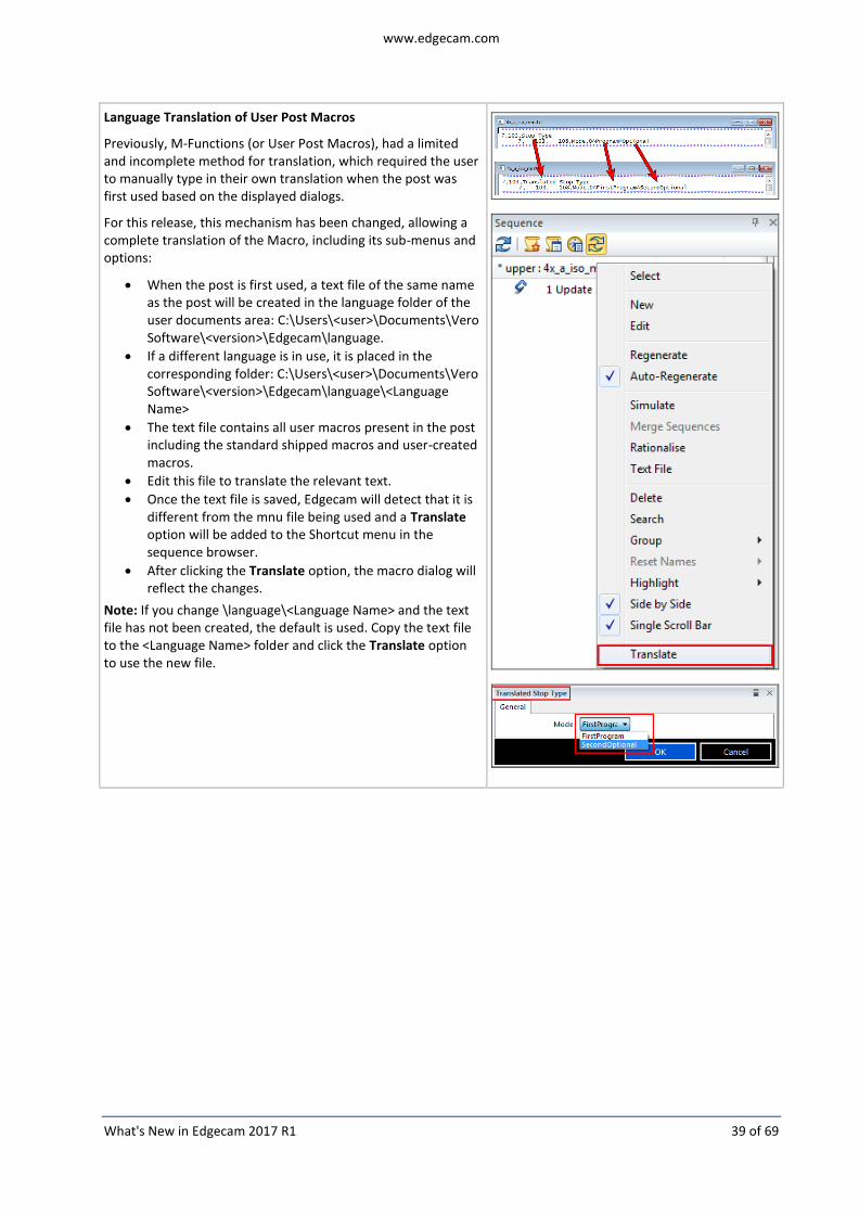
Language Translation of User Post Macros
Previously, M-Functions (or User Post Macros), had a limited and incomplete method for translation, which required the user to manually type in their own translation when the post was first used based on the displayed dialogs.
For this release, this mechanism has been changed, allowing a complete translation of the Macro, including its sub-menus and options:
When the post is first used, a text file of the same name as the post will be created in the language folder of the user documents area: C:\Users\<user>\Documents\Vero Software\<version>\Edgecam\language.
If a different language is in use, it is placed in the corresponding folder: C:\Users\<user>\Documents\Vero Software\<version>\Edgecam\language\<Language Name>
The text file contains all user macros present in the post including the standard shipped macros and user-created macros.
Edit this file to translate the relevant text.
Once the text file is saved, Edgecam will detect that it is different from the mnu file being used and a Translate option will be added to the Shortcut menu in the sequence browser.
After clicking the Translate option, the macro dialog will reflect the changes.
Note: If you change \language\<Language Name> and the text file has not been created, the default is used. Copy the text file to the <Language Name> folder and click the Translate option to use the new file.

www.edgecam.com
What's New in Edgecam 2017 R1 40 of 69
Manufacture Enhancements
Turning with Rotating Heads (Multi Task Machines)
For this release, we have introduced support for Milling machines that do turning by rotating a turn tool. This is usually seen when machining very large components where the part is stationary and the machine moves around to machine the turn profiles, typically large bores. The turning diameter is controlled by a secondary axis attached to the head.
The first configuration to be supported is a Horizontal Machine with a B-axis on table.
Note: ‘Advanced Multi Task Machine Options’ is required to use the Auxiliary X Axis functionality. The prerequisite for this module is an Advanced Production or Ultimate Production license.
This involves enhancements to Edgecam, Code Wizard / Code Generator and the Simulator:
Edgecam
Sequence creation The machine needs to be registered in Machine Manager for Edgecam to accept setting a sequence up 'as milling'. The sequence can be setup either as milling or as turning, as for other MTM machines. However, we suggest that sequences are setup as milling because turning will not allow changes on part positioning; there is no real Turn spindle on this machine.
www.edgecam.com
What's New in Edgecam 2017 R1 41 of 69
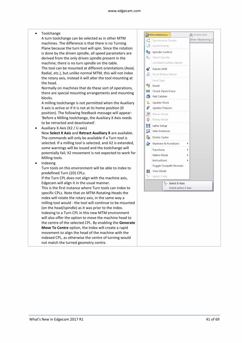
Toolchange A turn toolchange can be selected as in other MTM machines. The difference is that there is no Turning Plane because the turn tool will spin. Since the rotation is done by the driven spindle, all speed parameters are derived from the only driven spindle present in the machine; there is no turn spindle on the table. The tool can be mounted at different orientations (Axial, Radial, etc.), but unlike normal MTM, this will not index the rotary axis, instead it will alter the tool mounting at the head. Normally on machines that do these sort of operations, there are special mounting arrangements and mounting blocks. A milling toolchange is not permitted when the Auxiliary X axis is active or if it is not at its home position (0 position). The following feedback message will appear: 'Before a Milling toolchange, the Auxiliary X Axis needs to be retracted and deactivated'.
Auxiliary X Axis (X2 / U axis) New Select X Axis and Retract Auxiliary X are available. The commands will only be available if a Turn tool is selected. If a milling tool is selected, and X2 is extended, some warnings will be issued and the toolchange will potentially fail; X2 movement is not expected to work for Milling tools.
Indexing Turn tools on this environment will be able to index to predefined Turn (2D) CPLs. If the Turn CPL does not align with the machine axis, Edgecam will align it in the usual manner. This is the first instance where Turn tools can index to specific CPLs. Note that on MTM-Rotating-Heads the index will rotate the rotary axis, in the same way a milling tool would - the tool will continue to be mounted (on the head/spindle) as it was prior to the index. Indexing to a Turn CPL in this new MTM environment will also offer the option to move the machine head to the centre of the selected CPL. By enabling the Generate Move To Centre option, the Index will create a rapid movement to align the head of the machine with the indexed CPL, as otherwise the centre of turning would not match the turned geometry centre.

www.edgecam.com
What's New in Edgecam 2017 R1 42 of 69
Move To Toolchange When moving to Toolchange or Home position, the Auxiliary X Axis can also be retracted. Therefore, the Move to Toolchange and Move To Home commands now contain an Auxiliary Axis option when a Turn tool is being moved. The Auxiliary Axis can be set to remain Fixed, or to retract before or after the main axis.
Code Wizard / Code Generator
When creating a Mill machine, and selecting 'Turning Capability', Code Wizard will allow you to select a Horizontal configuration, which will then automatically select the secondary X axis:
Template The templates are the MTM templates (Multi Task Machines), as these contain a combination of a milling machine plus turning cycles and turning toolchange. Some additions for the Auxiliary X Axis are present, for example, tokens, NC-Style tab, and formats. In principle, the output of the secondary X axis functions in the same way as Auxiliary Z Axis (Quills). The user needs to place the token [AUXXMOVE] where and if necessary, as it is not added to the default output.
Auxiliary X Axis (as a device) The Auxiliary X Axis is inserted upon the driven spindle, as this is the kinematic arrangement that allows it to alter the turning diameter during a turn cycle. The X2 movement, combined with the driven rotation of the head, will provide the ability to create a turned profile.
System variables / Macros Similar to Quills, two new macros are available:
%MACRO=722=..=Select X Axis= for Selecting / Deselecting X2 axis
%MACRO=725=..=Retract X Auxiliary= for the retraction move The ACTIVEX System variable identifies whether the secondary axis is active, and X2MOVE details by how much it is extended at each given move.
Simulator
Simulator will represent the rotation of the tool assembled on the auxiliary axis. Tool and fixtures / holders will generate a spun profile, which can fully detect collisions.
Spindle Control can be used to control the spinning. For these machines it is normally a request to start spinning only when the tool is ready to start cutting. For this, the user can set the tool to Stopped at toolchange, and later (immediately before the cycle) reactivate the spindle rotation using a Spindle Control command:
This is fully replicated in the NC code.

www.edgecam.com
What's New in Edgecam 2017 R1 43 of 69
Support for Nutated Heads (Multi Task Machines)
We now support Nutated Heads on Multi Task Machines.
As for normal machines, only XZ and YZ turning planes are allowed.
When the axis is nutated, a rotation can easily result in the turning axis not being aligned with XZ or YZ because the rotation takes place around more than one axis. Therefore, Edgecam will check the nutated axis and offer only the available orientations. 'Angle' is also available but the toolchange itself will fail if the selected 'Angle' is not achievable.
It is important to consider the following points for nutated configurations:
Imprecision when specifying the vector of the nutated axis may result in orientations other than Axial not being available. For example, a vector of [0,57735 ; 0.57735 ; 0.57735] would result in the axis being 'nutated' about all three axis by 45 degrees. That means the table could achieve a 'Radial' (or 'Reverse Radial') orientation by rotating the table by 120 degrees (machine angle). Straight to the point, non-Axial orientations will only be available if the turn axis becomes perfectly perpendicular when attempting to achieve them.
Tools in non-axial planes may diverge from axial ones in their hand / orientation. On normal machines, the CPL will rotate evenly with the rotary axis, always resulting in a situation where its alignment still matches the tool orientation. A 'left handed non-reversed' tool will always be 'left handed non-reversed' on a normal machine. On nutated machines, because the CPL rotates about two or three axes, the tool needs to be reversed to still respect its hand in relation to the CPL.
Profiling Cycle - Break Corners options with Geometry Compensation
Previously, when Geometry compensation was in use, users were limited to the Sharp and Round corner strategies in the Profiling cycle. To enhance the capabilities of the cycle, we have now added more corner strategies:
Notes:
When compensation is being used, the High Speed and Sharp corner strategies will produce the same NC Code as the Round strategy if the back offset is identical. In the machine, Sharp and High Speed are probably not applicable; a Feedback message has been added to these cases to warn the user.
For the Twizzle corner strategy, it is important that the generated NC Code is tested in the machine first. Some controllers might encounter problems with the toolpath crossing itself.
www.edgecam.com
What's New in Edgecam 2017 R1 44 of 69
Operations Improvements
The Edgecam Operations have been improved in the following area:
Index All Milling Operations that can machine 2D Features will apply a safe Index command when the selected feature belongs to a plane other than the current plane. The user is required to select the feature from a single plane. Multiple features can be selected in that plane but the Operation cannot perform multiple indexes.
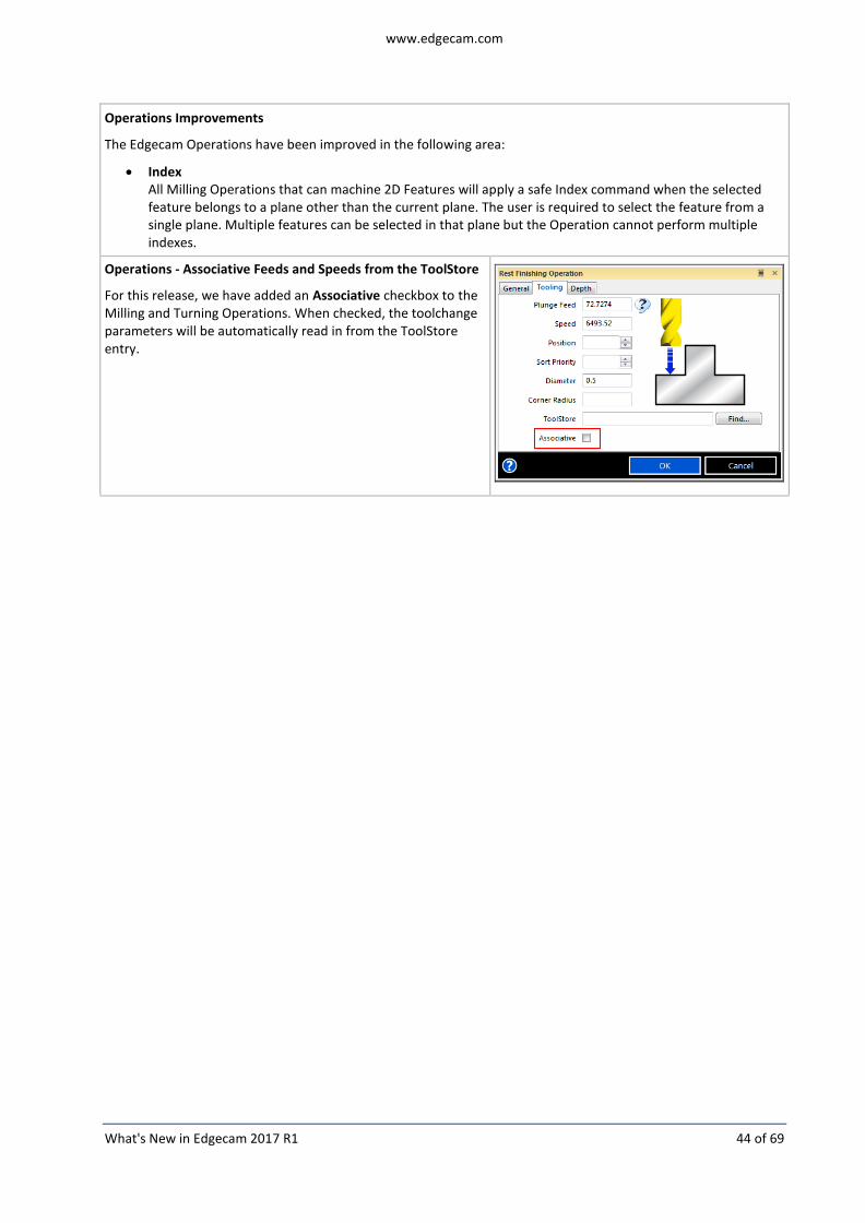
Operations - Associative Feeds and Speeds from the ToolStore
For this release, we have added an Associative checkbox to the Milling and Turning Operations. When checked, the toolchange parameters will be automatically read in from the ToolStore entry.

www.edgecam.com
What's New in Edgecam 2017 R1 45 of 69
Trim to Face Silhouette check box added to the Cycles
A new Trim to Face Silhouette check box has been added to the Control tab of the Parallel Lace, Constant Cusp Finishing, Rest Finishing and Pencil Mill cycles. When checked, a boundary is automatically generated from the silhouette of the selected faces and used to trim the tool path.
Note: This modifier is for compatibility with pre 2015 R2 cycles using Features. It is NOT displayed on the dialog by default but can be displayed by creating a mask and making it visible by setting the initial modifier value to On.
Comment field added to the Cycles
A new Comment field has been added to the General tab of the Milling and Turning cycles.
A general description of the cycle can be entered which is output through the Comment code constructor.

www.edgecam.com
What's New in Edgecam 2017 R1 46 of 69
Indexing and CPL Handling
A new Define CPL Name modifier has been added to the Index dialog - General tab.
Define CPL Name is a string, where the user can dynamically assign a new name to the CPL being indexed. Basically, Edgecam will create a copy of the resultant indexed CPL with the assigned name. Define CPL Name works in conjunction with the automatic realignment and alternative rotational solution but, because it is a new CPL, the usual warnings are not necessary and are omitted.
Note: The new modifier is only available for Indexing (Milling and MTM).
Advanced Five Axis Improvements
A number of improvements have been implemented in the Surface, Port and Multiblade modules:
Calculation based on Surfaces Collision check - Move tool away on tool plane
The aim is to be able to move the tool in its tool plane; the tool plane in the plane that is normal to the tool axis. If a collision occurs, the tool will be pushed on the tool plane but orthogonal to the cutting direction.
The main benefit is that this collision avoidance is independent of the machined surfaces and it will not push the tool into a specific single direction. As the tool moves it can compensate collisions in its plane while maintaining the tool orientation or height. That is applicable when, for example, the tilting is set to be relative to cutting direction.
See Strategy and parameters on the Gouge check tab.

www.edgecam.com
What's New in Edgecam 2017 R1 47 of 69
Calculation based on Surfaces – Flowline
The flowline will create a toolpath that is aligned (or mapped) to the U or V direction of the machining surface. The user can choose the direction from the interface. Note that only a single surface can be machined at a time.
The main benefit is that the flowline toolpath can be created without selecting additional bounding geometries such as wall surfaces or edge curves. The maximum stepover can be maintained with a constant distance even if the surface topology is very complex. Also, calculation time is very fast. The only issue is that only a single surface can be machined at a time because, with multiple surfaces, multiple ISO directions can occur which would cause the pattern to break.
See Pattern list on the Surface Paths tab.
Calculation based on Surfaces - Mirror Tool path
Creates a mirror image of a toolpath by reflecting it symmetrically with respect to a defined axis and point.
See Mirror on the Roughing tab.
SWARF machining - Maximum angle step for rotation axis
Limits the rotation angle of the machine head to a specified value measured from the last toolpath point. If the rotation angle is too large due to the kinematic properties of the machine, the distance between two toolpath points will be refilled with additional points. The number of points is calculated by division of rotation angle and maximum angle step. The result is an angle change in small steps.
Some machine controls are not able to determine how to compensate large rotation angles resulting in unpredictable tool movements which cause surface or even tool damage.
See Max. angle step for rotation axis on the Utility tab.

www.edgecam.com
What's New in Edgecam 2017 R1 48 of 69
Port Machining - Edge rolling
Edge rolling will create a toolpath extension enabling the tool to approach and enter the port in a smooth and gradual manner. The flute cuts out material step by step from the tip and is not in full contact with the material on full diameter.
See Roll over edge on the Surface Path tab.
Port Machining - Automatic Spine
The behaviour of automatic spine creation for port machining has changed. To create a toolpath, there must be sufficient space between the spine and the machining surface. In previous versions, no toolpath was created when any part of the spine was too close to the machining surface. With the new behaviour, the toolpath is created up to the point where the spine gets too close to the machining surface. The resulting toolpath is checked for collisions up to this point.
See Automatic spine on the Surface Path tab.
Multiblade machining - Fillet machining
This finishing cycle creates a finishing toolpath on the fillet area between the hub and the blade.
The system automatically finds the fillet of the part. The area to be machined on the hub and shroud can be defined by:
A determined number of cuts and a stepover distance
A big tool diameter. Define the roughing tool diameter to determine which area of the fillet could not be machined. Additionally, an overlap can be set.
See Pattern on the Surface Path tab.
www.edgecam.com
What's New in Edgecam 2017 R1 49 of 69
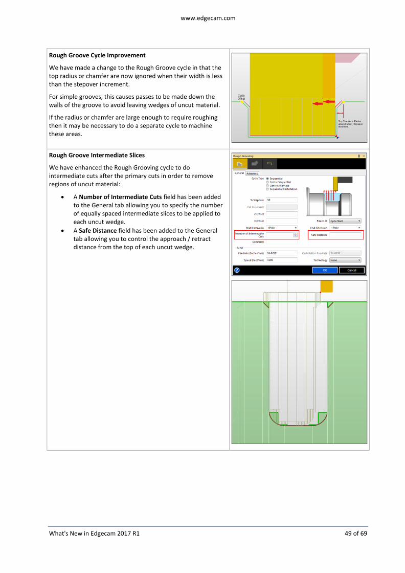
Rough Groove Cycle Improvement
We have made a change to the Rough Groove cycle in that the top radius or chamfer are now ignored when their width is less than the stepover increment.
For simple grooves, this causes passes to be made down the walls of the groove to avoid leaving wedges of uncut material.
If the radius or chamfer are large enough to require roughing then it may be necessary to do a separate cycle to machine these areas.
Rough Groove Intermediate Slices
We have enhanced the Rough Grooving cycle to do intermediate cuts after the primary cuts in order to remove regions of uncut material:
A Number of Intermediate Cuts field has been added to the General tab allowing you to specify the number of equally spaced intermediate slices to be applied to each uncut wedge.
A Safe Distance field has been added to the General tab allowing you to control the approach / retract distance from the top of each uncut wedge.

www.edgecam.com
What's New in Edgecam 2017 R1 50 of 69
Pathcomp added to Rough Grooving cycle
The Rough Groove toolpath now generates a compensated toolpath which considers the tool tip radius; for existing parts, the original behaviour is maintained.
Turning approach for Tapered Threads
For this release, the Thread cycle has a different approach mechanism to prevent problems with Tapered Threads.
Edgecam now ensures that the approach move will always be above the Start/End of the profile. This has been adjusted to avoid problems with Canned Cycle and Single Block output which could potentially cause machines to indicate an alarm because the Cycle Start point was below the X end coordinate of the tapered thread.
Notes:
This also works for internal tapered threads as the approach will send the tool to a lower coordinate than the profile start/end.
“Finish At” set to “Cycle Start” will respect the approach move coordinate.
This change also influences the longhand output.
Previously, this adjustment was partially done in the post processor. We now handle this adjustment in Edgecam providing a more reliable simulation.
vs
www.edgecam.com
What's New in Edgecam 2017 R1 51 of 69
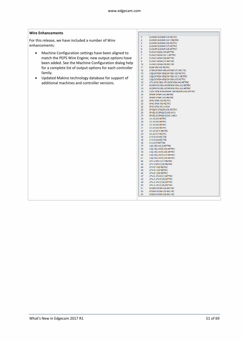
Wire Enhancements
For this release, we have included a number of Wire enhancements:
Machine Configuration settings have been aligned to match the PEPS Wire Engine; new output options have been added. See the Machine Configuration dialog help for a complete list of output options for each controller family.
Updated Makino technology database for support of additional machines and controller versions.

www.edgecam.com
What's New in Edgecam 2017 R1 52 of 69
Rotary Axis Controls - Wire
Rotary Axis controls have been added to the General tab of the Move Wire command which allow the rotary and linear axes to be moved simultaneously or independently.
A new Rotary tab which allows rotary axis configuration when positioning using the Move Wire command has been added to the following machine controls:
ACcut.
AccuteX.
ACfanuc.
ACmillennium.
ACVision.
Chmer.
Fanuc.
Makino.
Mitsubishi.
Sodick.
www.edgecam.com
What's New in Edgecam 2017 R1 53 of 69
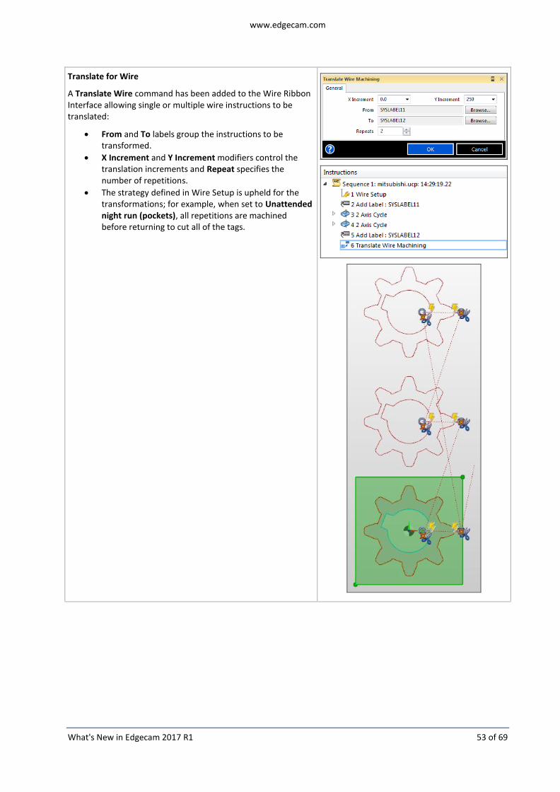
Translate for Wire
A Translate Wire command has been added to the Wire Ribbon Interface allowing single or multiple wire instructions to be translated:
From and To labels group the instructions to be transformed.
X Increment and Y Increment modifiers control the translation increments and Repeat specifies the number of repetitions.
The strategy defined in Wire Setup is upheld for the transformations; for example, when set to Unattended night run (pockets), all repetitions are machined before returning to cut all of the tags.

www.edgecam.com
What's New in Edgecam 2017 R1 54 of 69
Probing Cycles support Direct Picking on a Solid
For this release, we have added support for direct picking on a solid to Probing Cycles.
This gives the ability to use Probing cycles without needing to create / extract wireframe geometry from the model.
The cycles can pick:
Linear edges (endpoints and midpoints).
Vertices.
Circular edges and faces.
These picks are associative to the model which means that the toolpath updates following a design change to the solid.
However, a limitation exists in that edge midpoint and face centre point picks remain non-associative.
Multiple Hole Templates Now Found
For this release, we have added the ability for multiple hole templates to be able to be found in a single hole definition. This allows users dealing with complex holes to be able to match the steps of the hole to pre-saved hole templates.
When constructing hole templates that will be used to find partial hole definitions in a larger hole definition, set the Match To Subset flag to Yes using the drop-down list.
Create Sequence - Update Stock modifiers
For the previous release, in milling, we added the ability to define Update Stock automatic parameters using PCI variables. These milling parameters can now be defined using the Update Stock option in the Create Milling Sequence dialog:
Those fields will populate the PCI variables that were created in the 2016 R1 release.
Note that the Update Stock command is not modal. If you call a new Update Stock command later, you will need to remember which settings you set up for consistency.

www.edgecam.com
What's New in Edgecam 2017 R1 55 of 69
Manual Turn Profile Features - Ability to re-select Entities during an Edit
For this release, we have improved the editing of Manual Turn Profiles.
Previously, the user had no way of editing selected entities for the turn profile; only the front and rear extensions could be edited. The profiles defined in Manual Turn Features can now be redefined.
Note: Once the Turn Profile Feature has been saved as a template it is not possible to edit the subsequently 'found' template profile. Should you wish to edit a template, it needs to be redefined on the feature from which it was created.
Before
After

www.edgecam.com
What's New in Edgecam 2017 R1 56 of 69
Interface Enhancements
Component Setup replaced by Setup Browser
For this release, we have replaced the Component Setup dialog with the Setup Browser window.
Insert Solid - Automatic Alignment
For this release, when inserting a solid, a message will be displayed indicating whether or not the solid will be automatically aligned.
The location and orientation of the solid can be manually changed by clicking Change Alignment Options.
Note: This will disable automatic alignment.
Workflow View and Render Buttons
For this release, we have re-introduced the options to toggle the display of different machine parts (Base, Guards, Axes, Turret and Table). We have also added the options to Show or Hide all of the machine graphics.

www.edgecam.com
What's New in Edgecam 2017 R1 57 of 69
Images on Dialogs (Milling Cycles)
As part of our continuing effort to improve the user experience, images and help tooltips have been added to the following machining cycles:
Plunge Roughing.
Project Toolpath.
Five Axis - Depth tab.
Rest Finishing.
Project Boundary Collapse.

www.edgecam.com
What's New in Edgecam 2017 R1 58 of 69

www.edgecam.com
What's New in Edgecam 2017 R1 59 of 69
Feature Find Hole Grouping
For this release, we have added a new Through Clearance option to the Hole Options on the Mill tab. This allows you to group similar holes based on the Through Clearance value that you specify.
Similar holes can have different clearances beneath them and may not be recognised and grouped together. Use this setting to define the clearance beneath the hole for which holes will be grouped provided that the Through Clearance distance contains no faces.
The Through Clearance option has also been added to General tab of the Hole Feature and Group Hole Features dialogs.
www.edgecam.com
What's New in Edgecam 2017 R1 60 of 69
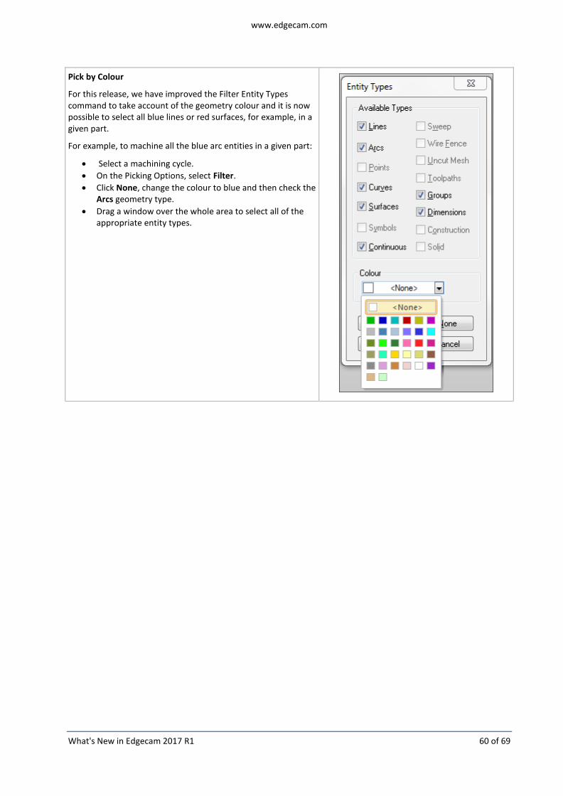
Pick by Colour
For this release, we have improved the Filter Entity Types command to take account of the geometry colour and it is now possible to select all blue lines or red surfaces, for example, in a given part.
For example, to machine all the blue arc entities in a given part:
Select a machining cycle.
On the Picking Options, select Filter.
Click None, change the colour to blue and then check the Arcs geometry type.
Drag a window over the whole area to select all of the appropriate entity types.
www.edgecam.com
What's New in Edgecam 2017 R1 61 of 69
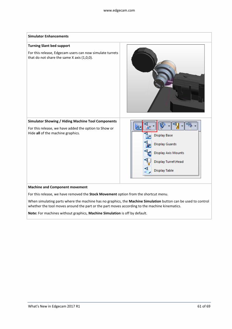
Simulator Enhancements
Turning Slant bed support
For this release, Edgecam users can now simulate turrets that do not share the same X axis (1,0,0).
Simulator Showing / Hiding Machine Tool Components
For this release, we have added the option to Show or Hide all of the machine graphics.
Machine and Component movement
For this release, we have removed the Stock Movement option from the shortcut menu.
When simulating parts where the machine has no graphics, the Machine Simulation button can be used to control whether the tool moves around the part or the part moves according to the machine kinematics.
Note: For machines without graphics, Machine Simulation is off by default.

www.edgecam.com
What's New in Edgecam 2017 R1 62 of 69
Edgecam Workflow Solids
IGES Import
For this release, we have added the ability to import IGES files into EWS:
added to the Storyboard after importing allowing wireframe entities to be individually selected.
When creating a ruled part suitable for wire EDM, a second sketch can be created when extracting entities from an IGES file using the Extract from Wireframe button.
www.edgecam.com
What's New in Edgecam 2017 R1 63 of 69
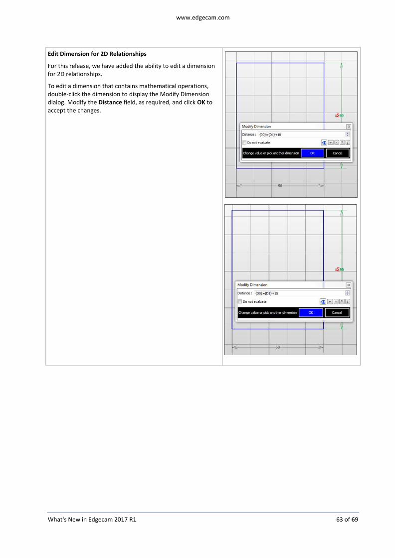
Edit Dimension for 2D Relationships
For this release, we have added the ability to edit a dimension for 2D relationships.
To edit a dimension that contains mathematical operations, double-click the dimension to display the Modify Dimension dialog. Modify the Distance field, as required, and click OK to accept the changes.

www.edgecam.com
What's New in Edgecam 2017 R1 64 of 69
Code Wizard Enhancements
Support for non-collinear turrets (Slant Turrets)
For this release, users can now simulate turrets that do not share the same X Axis (1,0,0).
By changing the X-axis properties, the turret will machine the turning profile at a different angle (not 180°). This is replicated in the Simulator as the toolpath and tool positions are rotated by a given angle that represents the machine tree settings.
Error messages will be displayed when the user attempts to program unsupported instructions, for example, simultaneous instructions, with driven tools, in both lower and upper turrets.
Notes:
1. As machines with Slant Turrets are expected to have the capability to compensate the turret angle offset, users will only experience changes in the Simulator. No changes in the output code / post templates / internal simulation are expected. In addition, it is important to recognise that parametric graphics will not be precisely visualised in Code Wizard because there is no change in the Graphics or Home positions.
2. Machines with the turrets facing the Spindle will also have to be changed in the “Turret” direction which represents a vector in which the tools are mounted around. A regular turret is usually set with a vector of (0,0,1) while a turret facing the spindle needs to be corrected to the same vector set in the X Axis.
3. Slant Turrets is a different machine configuration to Compound Axes Turrets. In Slant Turrets, X, Y and Z are considered to be perpendicular to each other. Compound Axes Turrets will independently move in vectors that do not have 90° of angular difference. When a Slant Turret is being configured, the user needs to ensure that the vectors set for X and Y axes will be perpendicular.

www.edgecam.com
What's New in Edgecam 2017 R1 65 of 69
Axial Rotary Output in Polar Mode
Work has been done in the adaptive turning templates to improve flexibility in the application of 'Polar' mode to rotary axial moves. The controlling tab in 'NC Style' has been renamed 'C/Y Rotary (Polar) Axial Milling and new options to “Exclude Rapids from Manual Polar have been added.
If Polar Switching is set to Automatic, the changes should be minimal except that identification of rapids converted to feed and thus included/excluded from the polar condition is improved.
Polar switching set to Manual will do what is requested and change to Polar Mode when the instruction is used within the sequence. Use of the new option will allow delay of the application until after the Rapid after Toolchange or to exclude all rapid moves before and after the polar cutting moves. This option is designed to help in cases where rapid approaches are created by a cycle following the use of manual polar.
Notes:
1. Use of delay or automatic does mean that the transition to Polar may not coincide with the sequence switch to Rotary and that this could result in Simulation differences from the NC code.
2. Users should satisfy themselves that these changes are compatible with the requirements of their particular machine before use on production work.

www.edgecam.com
What's New in Edgecam 2017 R1 66 of 69
Code Generator Enhancements
New Milling Macros
Two new Milling Macros have been added to the Code Generator:
Milling Macro Reference (MACRO 722 - SELECT X AXIS).
Milling Macro Reference (MACRO 725 - RETRACT AUXILIARY X AXIS).

www.edgecam.com
What's New in Edgecam 2017 R1 67 of 69
ToolStore Enhancements
HTML Job Reports have been completely removed
The Old HTML Job Reports have been completely removed.
These were superseded by Live Job Reports in a previous release but some references to them remained in the ToolStore Applications and File Locations.
All references to the HTML reports have now been removed from the software.
T-Slot Cutters - Additional Gauge Point added
For this release, we have added a Secondary Gauge Point for T-Slot milling cutters. The Secondary Gauge Point enables the gauge point to be set at the top of the flute.
This makes it easier to set the depth in the cycle when cutting with the top edge of the cutter.
Changing the set point from Primary to Secondary and vice versa causes the Z Gauge value to update; a separate tool length offset is required for each gauge point setting.
On the Edgecam Milling Cutter dialog, the gauge point is set on the Loading tab.
Note: When setting the Z clearance value in the cycle, you need to allow for the depth of the flute and adjust accordingly.

www.edgecam.com
What's New in Edgecam 2017 R1 68 of 69
Inscribed Circle added to Turn Thread Tool insert definition
An Inscribed Circle modifier has been added to the turn thread tool definition in ToolStore and Edgecam to help control the size of the threading insert. In previous versions, the insert size was based on a proportion of the insert reach. The insert size is now controlled by the Inscribed circle value unless the insert reach becomes too big in which case it reverts back to a proportion of reach.

www.edgecam.com
What's New in Edgecam 2017 R1 69 of 69
Strategy Manager Enhancements
JavaScript Engine
Strategy Manager has been improved by adding JavaScript string functions to the Decision and Data Nodes.
Functions such as IF INCLUDES, OR, MID and LEN now have equivalent JavaScript functions which reduces the complexity of the logic necessary and increases the opportunities to access data and output debug information.
The use of JavaScript Engine by the strategies also means that Edgecam can understand and apply the decisions much faster. Decision and Data nodes are 15~20 times faster, in general, but may be up to 50x faster. They are one of the reasons why regenerating a part is different to applying a strategy and these savings should improve performance when applying strategies.
User Interface Improvements
Process Browser - Allow Sorting and Drag and Drop To reorder processes in the Process Browser, either right-click on the browser and click Sort Processes By Name or drag and drop the processes.
Process Browser - Cut, Copy and Paste using keyboard To Cut, Copy and Paste processes in the Process Browser, use the CTRL + X / C / V keyboard shortcuts , respectively.
Delete processes, nodes and constraints using keyboard To delete processes, nodes and constraints, use the Delete button from the keyboard.
Remove zeros after the decimal separator Zeros after the decimal separator are no longer generated by Strategy Manager.