geotechnical investigation proposed commercial/industrial building … dr 16-014... · ·...
TRANSCRIPT

GEOTECHNICAL INVESTIGATIONPROPOSED COMMERCIAL/INDUSTRIAL
BUILDINGNWC 5th Street and Church Avenue
Highland, Californiafor
Real Estate Development Associates

22885 Savi Ranch Parkway Suite E Yorba Linda California 92887voice: (714) 685-1115 fax: (714) 685-1118 www.socalgeo.com
January 4, 2015
Real Estate Development Associates4100 MacArthur Boulevard, Suite 120Newport Beach, California 92660
Attention: Mr. Bill Goltermann
Project No.: 15G221-1
Subject: Geotechnical InvestigationProposed Commercial/Industrial BuildingNWC 5th Street and Church AvenueHighland, California
Gentlemen:
In accordance with your request, we have conducted a geotechnical investigation at the subjectsite. We are pleased to present this report summarizing the conclusions and recommendationsdeveloped from our investigation.
We sincerely appreciate the opportunity to be of service on this project. We look forward toproviding additional consulting services during the course of the project. If we may be offurther assistance in any manner, please contact our office.
Respectfully Submitted,
SOUTHERN CALIFORNIA GEOTECHNICAL, INC.
Pablo Montes Jr.Staff Engineer
John A. Seminara, GE 2294Principal Engineer
Distribution: (2) Addressee

Proposed Commercial/Industrial Building – Highland, CaliforniaProject No. 15G221-1
TABLE OF CONTENTS
1.0 EXECUTIVE SUMMARY 1
2.0 SCOPE OF SERVICES 3
3.0 SITE AND PROJECT DESCRIPTION 4
3.1 Site Conditions 43.2 Proposed Development 4
4.0 SUBSURFACE EXPLORATION 6
4.1 Scope of Exploration/Sampling Methods 64.2 Geotechnical Conditions 6
5.0 LABORATORY TESTING 8
6.0 CONCLUSIONS AND RECOMMENDATIONS 10
6.1 Seismic Design Considerations 106.2 Geotechnical Design Considerations 116.3 Site Grading Recommendations 136.4 Construction Considerations 166.5 Foundation Design and Construction 176.6 Floor Slab Design and Construction 186.7 Retaining Wall Design and Construction 196.8 Pavement Design Parameters 22
7.0 GENERAL COMMENTS 24
APPENDICES
A Plate 1: Site Location MapPlate 2: Boring and Trench Location Plan
B Boring and Trench LogsC Laboratory Test ResultsD Grading Guide SpecificationsE Seismic Design Parameters

Proposed Commercial Industrial Building – Highland, CaliforniaProject No. 15G221-1
Page 1
1.0 EXECUTIVE SUMMARY
Presented below is a brief summary of the conclusions and recommendations of thisinvestigation. Since this summary is not all inclusive, it should be read in complete context withthe entire report.
Site Preparation• Initial site preparation should include demolition of the existing structures, including floor
slabs, foundations, utilities, septic systems, and any other improvements that will notremain in place with the new development. Debris resulting from the demolition should bedisposed of off-site. Concrete and asphalt debris may be re-used within the compacted fills,provided they are crushed and the maximum particle size is less than 2 inches. The existingaggregate base material can also be well-mixed with the on-site soils and incorporated intonew structural fill.
• Initial site preparation should also include stripping of any surficial vegetation. The surficialvegetation including shrubs, trees, root masses and any organic soils should be properlydisposed of off-site.
• Several of the borings and trenches encountered fill soils extending to depths of 1½ to3½± feet. No documentation regarding the placement and compaction of these soils hasbeen provided. These undocumented fill soils are not considered suitable for the support ofthe proposed building. The near-surface alluvial soils possess varying densities and a minorpotential for consolidation/collapse.
• Remedial grading is recommended within the proposed building and improvement areas inorder to remove all of the artificial fill materials, any soils disturbed during demolition, andthe upper portion of the near-surface native alluvial soils. The existing soils within theproposed building area should be overexcavated to a depth of at least 3 feet below existinggrade and to a depth of at least 3 feet below proposed pad grade. Within the building area,the proposed foundation influence zones should be overexcavated to a depth of 3 feetbelow proposed foundation bearing grade.
• Following evaluation of the subgrade by the geotechnical engineer, the exposed subgradesoils should be scarified, moisture conditioned as necessary, and recompacted. Theresulting soils may be replaced as structural fill, compacted to 90 percent of the ASTM D-1557 maximum dry density.
• The on-site soils contain significant amounts of oversized materials, including cobbles andboulders. Where grading will require excavation into these materials, consideration shouldbe given to using selective grading techniques to remove the cobbles and/or boulders fromthese soils prior to reuse as fill.
Building Foundations• Conventional shallow foundations, supported in newly placed compacted fill.• 2,500 lbs/ft2 maximum allowable soil bearing pressure.• Reinforcement consisting of at least two (2) No. 5 rebars (1 top and 1 bottom) in strip
footings. Additional reinforcement may be necessary for structural considerations.

Proposed Commercial Industrial Building – Highland, CaliforniaProject No. 15G221-1
Page 2
Building Floor Slabs• Conventional Slab-on-Grade, at least 5 inches thick.• Reinforcement is not required for geotechnical considerations. The actual floor slab
reinforcement to be determined by the structural engineer, based on the proposed loading.• Modulus of Subgrade Reaction: k = 150 psi/in.
Pavements
ASPHALT PAVEMENTS (R = 60)
Materials
Thickness (inches)
ParkingStalls
(TI = 4.0)
Auto DriveLanes
(TI = 5.0)
Truck Traffic
(TI = 6.0) (TI = 7.0) (TI = 8.0)
Asphalt Concrete 3 3 3½ 4 5
Aggregate Base 3 3 3 3 3
Compacted Subgrade 12 12 12 12 12
PORTLAND CEMENT CONCRETE PAVEMENTS (R=60)
Materials
Thickness (inches)
AutomobileParking andDrive Areas
Truck Traffic Areas
(TI =6.0) (TI =7.0) (TI =8.0)
PCC 5 5 6 7
Compacted Subgrade(95% minimum compaction)
12 12 12 12

Proposed Commercial Industrial Building – Highland, CaliforniaProject No. 15G221-1
Page 3
2.0 SCOPE OF SERVICES
The scope of services performed for this project was in accordance with our Proposal No.15P429, dated October 28, 2015. The scope of services included a visual site reconnaissance,subsurface exploration, field and laboratory testing, and geotechnical engineering analysis toprovide criteria for preparing the design of the building foundations, building floor slab, andparking lot pavements along with site preparation recommendations and constructionconsiderations for the proposed development. The evaluation of the environmental aspects ofthis site was beyond the scope of services for this geotechnical investigation.

Proposed Commercial Industrial Building – Highland, CaliforniaProject No. 15G221-1
Page 4
3.0 SITE AND PROJECT DESCRIPTION
3.1 Site Conditions
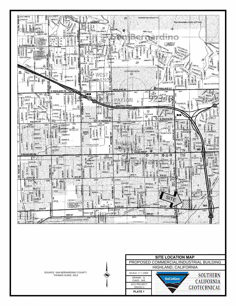
The subject site is located at the northwest corner of 5th Street and Church Avenue in Highland,California. The site is bounded to the north by City Creek channel, to the east by ChurchAvenue, to the south by 5th Street, and to the west by a truck parking lot. The general locationof the site is illustrated on the Site Location Map included as Plate 1 in Appendix A of thisreport.
The subject site consists of several irregular shaped parcels, which total 13.2± acres in size.The northern three-quarters (¾) of the site is developed with three (3) buildings and anenclosed canopy structure. These buildings are rectangular in shape and range from 2,220± ft2
to 6,000± ft2 in size. The buildings are of wood-frame, masonry block and light steel-frameconstruction, presumably supported on shallow foundations with concrete floor slabs. The areassurrounding these structures are generally utilized for construction equipment storage. A fuelpump island and an above-ground storage tank are located in the southwestern region of thisparcel. Ground surface cover generally consists of areas developed with crushed aggregatebase (CAB), asphaltic concrete pavements, and limited areas of Portland cement concrete (PCC)pavements.
The southern quarter (¼) of the overall site is developed with one (1) single-story officebuilding, located in the central area of this parcel. Ground surface cover surrounding thebuilding consists of asphaltic concrete pavements, utilized for automobile parking and driveareas. The southeast parcel is developed with a single family residence and a vacant lot. Theground surface cover consists of asphaltic concrete pavements surrounding the single familyresidence and exposed soil in the vacant lot.
Detailed topographic information was not available at the time of this report. Based on visualobservations, site grades appear to dip downwards toward the west at an estimated gradient ofapproximately 2 to 3± percent.
3.2 Proposed Development
Based on a conceptual site plan provided to our office by the client, the site will be developedwith one (1) commercial/industrial building, approximately 254,880± ft2 in size. The building willbe constructed in a cross-dock configuration with loading docks along the east and west sidesof the building. However, we understand that the client is also considering an alternative siteconfiguration and the proposed orientation of the building may be rotated. The building will belocated in the central area of the site. The building will be surrounded by asphaltic concretepavements in the parking and drive lanes and Portland cement concrete (PCC) pavements forthe loading dock areas. Several landscape planters and areas of concrete flatwork will beincluded throughout the site.
Proposed Commercial Industrial Building – Highland, CaliforniaProject No. 15G221-1
Page 5
Detailed structural information has not been provided. It is assumed that the new building willbe a single-story structure of tilt-up concrete construction, supported on a conventional shallowfoundation system with a concrete slab-on-grade floor. The construction may include a secondfloor mezzanine office. Based on the assumed construction, maximum column and wall loadsare expected to be on the order of 80 kips and 3 to 5 kips per linear foot, respectively.
Grading plans for the currently proposed development are currently unavailable. No significantamounts of below grade construction, such as basements or crawl spaces, are expected to beincluded in the proposed development. Based on the existing site topography, cuts and fills onthe order of 3 to 4± feet are expected to be necessary to achieve the proposed building padgrades.

Proposed Commercial Industrial Building – Highland, CaliforniaProject No. 15G221-1
Page 6
4.0 SUBSURFACE EXPLORATION
4.1 Scope of Exploration/Sampling Methods
The subsurface exploration conducted for this project consisted of six (6) borings advanced todepths of 5 to 25± feet below currently existing site grades. One of the borings was terminatedshallower than its proposed depth due auger refusal on cobbles and boulders. In addition to thesix borings, a total of four (4) trenches were excavated at the site to depths of 8½ to 10± feetbelow existing site grades. All of the borings and trenches were logged during drilling andexcavation by a member of our staff.
The borings were advanced with hollow-stem augers, by a conventional truck-mounted drillingrig. The trenches were excavated using a rubber tire backhoe with a 36-inch wide bucket.Representative bulk and in-situ soil samples were taken during drilling and excavation.Relatively undisturbed in-situ samples were taken with a split barrel “California Sampler”containing a series of one inch long, 2.416± inch diameter brass rings. This sampling method isdescribed in ASTM Test Method D-3550. In-situ samples were also taken using a 1.4± inchinside diameter split spoon sampler, in general accordance with ASTM D-1586. Both of thesesamplers were driven into the ground with successive blows of a 140-pound weight falling 30inches. The blow counts obtained during driving are recorded for further analysis. Bulk sampleswere collected in plastic bags to retain their original moisture content. The relativelyundisturbed ring samples were placed in molded plastic sleeves that were then sealed andtransported to our laboratory.
The approximate locations of the borings and trenches are indicated on the Boring and TrenchLocation Plan, included as Plate 2 in Appendix A of this report. The Boring and Trench Logs,which illustrate the conditions encountered at the boring and trench locations, as well as theresults of some of the laboratory testing, are included in Appendix B.
4.2 Geotechnical Conditions
Pavements
Two of the borings were drilled in areas paved with crushed aggregate base (CAB) or asphalticconcrete pavements. At Boring No. B-3, the ground surface was covered with 2± inches of CAB.At Boring No. B-5, the pavement section consists of 3½± inches of asphaltic concrete with nodiscernable underlying layer of aggregate base.
Artificial Fill
Artificial fill soils were encountered at the ground surface at all trench locations, and beneaththe pavements at Boring No. B-5. The fill soils generally consist of medium dense to dense siltysands and fine to medium sands, extending to depths of 1½ to 3½± feet below existing site
Proposed Commercial Industrial Building – Highland, CaliforniaProject No. 15G221-1
Page 7
grades. The fill soils possess a disturbed appearance, and some samples possess debris, suchas asphaltic concrete fragments, resulting in their classification as artificial fill.
Alluvium
Native alluvium was encountered beneath the fill soils or at the ground surface at all of theboring and trench locations. The alluvium generally consists of medium dense to very densefine to coarse sands, gravelly fine to coarse sands, and fine to coarse sandy gravels, withvarying amounts of silt, cobble and boulder content. The alluvium extends to at least themaximum depth explored of 25± feet.
Groundwater
Groundwater was not encountered during drilling of the borings. Based on the lack of any waterwithin the borings, and the moisture contents of the recovered soil samples, the staticgroundwater table is considered to have existed at a depth in excess of 25± feet at the time ofthe subsurface exploration.
As part of our research, we reviewed available groundwater data in order to determine thehistoric high groundwater level for the site. The primary reference used to determine recentwater level data was obtained from the California Department of Water Resources website,http://www.water.ca.gov/waterdatalibrary/. The nearest monitoring well is locatedapproximately 2,300 feet south of the site. Water level readings within this monitoring wellindicate high groundwater levels of 207± feet (October 2008), below the ground surface.

Proposed Commercial Industrial Building – Highland, CaliforniaProject No. 15G221-1
Page 8
5.0 LABORATORY TESTING
The soil samples recovered from the subsurface exploration were returned to our laboratory forfurther testing to determine selected physical and engineering properties of the soils. The testsare briefly discussed below. It should be noted that the test results are specific to the actualsamples tested, and variations could be expected at other locations and depths.
Classification
All recovered soil samples were classified using the Unified Soil Classification System (USCS), inaccordance with ASTM D-2488. The field identifications were then supplemented with additionalvisual classifications and/or by laboratory testing. The USCS classifications are shown on theBoring and Trench Logs and are periodically referenced throughout this report.
In-situ Density and Moisture Content
The density has been determined for selected relatively undisturbed ring samples. Thesedensities were determined in general accordance with the method presented in ASTM D-2937.The results are recorded as dry unit weight in pounds per cubic foot. The moisture contentsare determined in accordance with ASTM D-2216, and are expressed as a percentage of the dryweight. These test results are presented on the Boring and Trench Logs.
Consolidation
Selected soil samples were tested to determine their consolidation potential, in accordance withASTM D-2435. The testing apparatus is designed to accept either natural or remolded samplesin a one-inch high ring, approximately 2.416 inches in diameter. Each sample is then loadedincrementally in a geometric progression and the resulting deflection is recorded at selectedtime intervals. Porous stones are in contact with the top and bottom of the sample to permitthe addition or release of pore water. The samples are typically inundated with water at anintermediate load to determine their potential for collapse or heave. The results of theconsolidation testing are plotted on Plates C-1 through C-4 in Appendix C of this report.
Soluble Sulfates
A representative sample of the near-surface soils was submitted to a subcontracted analyticallaboratory for determination of soluble sulfate content. Soluble sulfates are naturally present insoils, and if the concentration is high enough, can result in degradation of concrete whichcomes into contact with these soils. The results of the soluble sulfate testing are presentedbelow, and are discussed further in a subsequent section of this report.
Sample Identification Soluble Sulfates (%) ACI Classification
B-3 @ 0 to 5 feet 0.003 Negligible

Proposed Commercial Industrial Building – Highland, CaliforniaProject No. 15G221-1
Page 9
Maximum Dry Density and Optimum Moisture Content
A representative bulk sample was tested for its maximum dry density and optimum moisturecontent. The results have been obtained using the Modified Proctor procedure, per ASTM D-1557. These tests are generally used to compare the in-situ densities of undisturbed fieldsamples, and for later compaction testing. Additional testing of other soil type or soil mixesmay be necessary at a later date. The results of the testing are plotted on Plate C-7 in AppendixC of this report.

Proposed Commercial Industrial Building – Highland, CaliforniaProject No. 15G221-1
Page 10
6.0 CONCLUSIONS AND RECOMMENDATIONS
Based on the results of our review, field exploration, laboratory testing and geotechnicalanalysis, the proposed development is considered feasible from a geotechnical standpoint. Therecommendations contained in this report should be taken into the design, construction, andgrading considerations. The recommendations are contingent upon all grading and foundationconstruction activities being monitored by the geotechnical engineer of record. The GradingGuide Specifications, included as Appendix D, should be considered part of this report, andshould be incorporated into the project specifications. The contractor and/or owner of thedevelopment should bring to the attention of the geotechnical engineer any conditions thatdiffer from those stated in this report, or which may be detrimental for the development.
6.1 Seismic Design Considerations
The subject site is located in an area which is subject to strong ground motions due toearthquakes. The performance of a site specific seismic hazards analysis was beyond the scopeof this investigation. However, numerous faults capable of producing significant ground motionsare located near the subject site. Due to economic considerations, it is not generally consideredreasonable to design a structure that is not susceptible to earthquake damage. Therefore,significant damage to structures may be unavoidable during large earthquakes. The proposedstructures should, however, be designed to resist structural collapse and thereby providereasonable protection from serious injury, catastrophic property damage and loss of life.
Faulting and Seismicity
Research of available maps indicates that the subject site is not located within an Alquist-PrioloEarthquake Fault Zone. Therefore, the possibility of significant fault rupture on the site isconsidered to be low.
Seismic Design Parameters
Beginning January 1, 2014, the 2013 CBC was adopted by all municipalities within SouthernCalifornia. The CBC provides procedures for earthquake resistant structural design that includeconsiderations for on-site soil conditions, occupancy, and the configuration of the structureincluding the structural system and height. The seismic design parameters presented below arebased on the soil profile and the proximity of known faults with respect to the subject site.
The 2013 CBC Seismic Design Parameters have been generated using U.S. Seismic DesignMaps, a web-based software application developed by the United States Geological Survey.This software application, available at the USGS web site, calculates seismic design parametersin accordance with the 2013 CBC, utilizing a database of deterministic site accelerations at 0.01degree intervals. The table below is a compilation of the data provided by the USGSapplication. A copy of the output generated from this program is included in Appendix E of thisreport. A copy of the Design Response Spectrum, as generated by the USGS application is also

Proposed Commercial Industrial Building – Highland, CaliforniaProject No. 15G221-1
Page 11
included in Appendix E. Based on this output, the following parameters may be utilized for thesubject site:
2013 CBC SEISMIC DESIGN PARAMETERS
Parameter Value
Mapped Spectral Acceleration at 0.2 sec Period SS 2.136
Mapped Spectral Acceleration at 1.0 sec Period S1 1.042
Site Class --- D
Site Modified Spectral Acceleration at 0.2 sec Period SMS 2.136
Site Modified Spectral Acceleration at 1.0 sec Period SM1 1.563
Design Spectral Acceleration at 0.2 sec Period SDS 1.424
Design Spectral Acceleration at 1.0 sec Period SD1 1.042
Liquefaction
Liquefaction is the loss of strength in generally cohesionless, saturated soils when the pore-water pressure induced in the soil by a seismic event becomes equal to or exceeds theoverburden pressure. The primary factors which influence the potential for liquefaction includegroundwater table elevation, soil type and plasticity characteristics, relative density of the soil,initial confining pressure, and intensity and duration of ground shaking. The depth within whichthe occurrence of liquefaction may impact surface improvements is generally identified as theupper 50 feet below the existing ground surface. Liquefaction potential is greater in saturated,loose, poorly graded fine sands with a mean (d50) grain size in the range of 0.075 to 0.2 mm(Seed and Idriss, 1971). Non-sensitive clayey (cohesive) soils which possess a plasticity indexof at least 18 (Bray and Sancio, 2006) are generally not considered to be susceptible toliquefaction, nor are those soils which are above the historic static groundwater table.
The California Geological Survey (CGS) has not yet conducted seismic hazard mapping in thearea of the subject site. The San Bernardino County Land Use Plan, Geologic Hazard Overlays,Redlands Quadrangle, FH31C, indicates that the subject site is not located within a zone ofliquefaction susceptibility. In addition, the subsurface conditions at the boring locations are notconsidered to be conducive to liquefaction. These conditions generally consist of medium denseto very dense, well graded, granular soils, and no evidence of a static water table within theupper 25± feet. Based on the mapping performed by San Bernardino County and the conditionsencountered at the boring and trench locations, liquefaction is not considered to be a designconcern for this project.
6.2 Geotechnical Design Considerations
General
Some of the boring and trench locations encountered fill soils, extending to depths of 1½ to3½± feet below existing site grades. Based on the varying strengths, and the lack of
Proposed Commercial Industrial Building – Highland, CaliforniaProject No. 15G221-1
Page 12
documentation regarding the placement and compaction of these soils, these soils areconsidered to represent undocumented fill. Additionally, the near-surface native soils generallypossess varying densities and a minor potential for consolidation/collapse. Based on theseconditions, the undocumented fill soils and near-surface alluvial soils are not considered suitableto support the foundation loads of the new building. The underlying soils generally consist ofhigh strength, dense to very dense, well graded sands and gravelly sands with moderateamounts of cobbles and occasional boulders. Based on these conditions, remedial grading isconsidered warranted within the proposed building area in order to remove all of theundocumented fill soils and a portion of the near surface native alluvial soils.
Settlement
The recommended remedial grading will remove the undocumented fill soils and the upperportion of the alluvium from within the proposed building area. The native soils that will remainin place below the recommended depth of overexcavation are generally dense to very denseand will not be subject to significant load increases from the foundations of the new structure.Therefore, following completion of the recommended remedial grading, post-constructionsettlements are expected to be within tolerable limits.
Expansion
The on-site soils generally consist of silty fine sands and fine to coarse sands with varyingamounts of silt, gravel, cobble and boulder content. These materials have been visuallyclassified as non-expansive. Therefore, no design considerations related to expansive soils areconsidered warranted for this site.
Soluble Sulfates
The results of the soluble sulfate testing indicate that the selected samples of the on-site soilscontain negligible concentrations of soluble sulfates, in accordance with American ConcreteInstitute (ACI) guidelines. Therefore, specialized concrete mix designs are not considered to benecessary, with regard to sulfate protection purposes. It is, however, recommended thatadditional soluble sulfate testing be conducted at the completion of rough grading to verify thesoluble sulfate concentrations of the soils which are present at pad grade within the buildingarea.
Shrinkage/Subsidence
Based on the results of the laboratory testing, removal and recompaction of the near surface fillsoils and dense native alluvium is estimated to result in an average shrinkage of 8 to 12percent. Minor ground subsidence is expected to occur in the soils below the zone of removal,due to settlement and machinery working. The subsidence is estimated to be 0.1± feet. Thisestimate may be used for grading in areas that are underlain by native alluvial soils.
These estimates are based on previous experience and the subsurface conditions encounteredat the boring locations. The actual amount of subsidence is expected to be variable and will bedependent on the type of machinery used, repetitions of use, and dynamic effects, all of whichare difficult to assess precisely.
Proposed Commercial Industrial Building – Highland, CaliforniaProject No. 15G221-1
Page 13
Grading and Foundation Plan Review
No grading and foundation plans were available at the time of this report. It is thereforerecommended that we be provided with copies of the preliminary plans, when they becomeavailable, for review with regard to the conclusions, recommendations, and assumptionscontained within this report.
6.3 Site Grading Recommendations
The grading recommendations presented below are based on the subsurface conditionsencountered at the boring and trench locations and our understanding of the proposeddevelopment. We recommend that all grading activities be completed in accordance with theGrading Guide Specifications included as Appendix D of this report, unless superseded by site-specific recommendations presented below.
Site Stripping and Demolition
The proposed development will require demolition of the existing structures. Demolition shouldinclude floor slabs, foundations, utilities, septic systems, and any other improvements that willnot remain in place with the new development. Debris resultant from demolition should bedisposed of off-site. Concrete and asphalt debris may be re-used within the compacted fills,provided they are crushed and the maximum particle size is less than 2 inches. The aggregatebase materials should be blended with the on-site soils and incorporated into structural fill soils.
Initial site stripping should include removal of any surficial vegetation. This should includeweeds, shrubs, trees and root-masses. The actual extent of site stripping should be determinedin the field by the geotechnical engineer, based on the organic content and stability of thematerials encountered.
Treatment of Existing Soils: Building Pad
Overexcavation should be performed within the proposed building area to remove all of theexisting undocumented fill soils, any soils disturbed during the demolition of the existingstructures, and the upper portion of the near-surface native alluvium. It is recommended thatthe existing undocumented fill soils be removed in their entirety. Based on conditionsencountered at the boring locations, these materials extend to depths of 1½ to 3½± feet. Thebuilding pad overexcavation should also extend to a depth of at least 3 feet below existinggrade and to a depth of at least 3 feet below proposed pad grade throughout the building area.Within the foundation influence zones, the overexcavation should extend to depths of at least 3feet below proposed foundation bearing grade.
The overexcavation areas should extend at least 5 feet beyond the building and foundationperimeters, and to an extent equal to the depth of fill below the new foundations. If theproposed structure incorporates any exterior columns (such as for a canopy or overhang) theoverexcavations should also encompass these areas.
Proposed Commercial Industrial Building – Highland, CaliforniaProject No. 15G221-1
Page 14
Following completion of the overexcavation, the subgrade soils within the building area shouldbe evaluated by the geotechnical engineer to verify their suitability to serve as the structural fillsubgrade, as well as to support the foundation loads of the new structures. This evaluationshould include proofrolling with a heavy rubber-tire vehicle to identify any soft, loose orotherwise unstable soils that must be removed. Some localized areas of deeper excavation maybe required if dry, loose, porous, low density or otherwise unsuitable materials are encounteredat the base of the overexcavation.
After a suitable overexcavation subgrade has been achieved, the exposed soilsshould be scarified to a depth of at least 12 inches, and thoroughly flooded to raisethe moisture content of the underlying soils to at least 2 to 4 percent aboveoptimum moisture content, extending to a depth of at least 24 inches. The exposedoverexcavation subgrades should be recompacted using heavy vibratory compaction equipmentprior to placement of any fill. The previously excavated soils may then be replaced ascompacted structural fill.
Treatment of Existing Soils: Retaining Walls and Site Walls
The existing soils within the areas of any proposed retaining walls and site walls should beoverexcavated to a depth of 3 feet below foundation bearing grade and replaced as compactedstructural fill as discussed above for the proposed building pad. Any undocumented fill soilswithin any of these foundation areas should be removed in their entirety. The overexcavationsubgrade soils should be evaluated by the geotechnical engineer prior to scarifying, moistureconditioning, and recompacting the upper 12 inches of exposed subgrade soils, as discussed forthe building areas. The previously excavated soils may then be replaced as compactedstructural fill.
Treatment of Existing Soils: Parking Areas
Based on economical considerations, removal and replacement of the existing potentiallycompressible/collapsible alluvium and undocumented fill is not considered warranted within theproposed parking areas. Subgrade preparation in the new parking and drive areas shouldinitially consist of removal of all soils disturbed during stripping operations. The geotechnicalengineer should then evaluate the subgrade to identify any areas of additional unsuitable soils.The subgrade soils should then be scarified to a depth of 12± inches, moisture conditioned to 2to 4 percent above optimum moisture content (to a depth of at least 24 inches) andrecompacted to at least 90 percent of the ASTM D-1557 maximum dry density.
The grading recommendations presented above for the proposed parking and drive areasassume that the owner and/or developer can tolerate minor amounts of settlement within theproposed parking areas. The grading recommendations presented above do not completelymitigate the extent of collapsible native soils or undocumented fill soils in the parking areas. Assuch, settlement and associated pavement distress could occur. Typically, repair of suchdistressed areas involves significantly lower costs than completely mitigating these soils at thetime of construction. If the owner cannot tolerate the risk of such settlements, the parking anddrive areas should be graded in a manner similar to that described for the building areas.
Proposed Commercial Industrial Building – Highland, CaliforniaProject No. 15G221-1
Page 15
Treatment of Existing Soils: Flatwork Areas
Subgrade preparation in the new flatwork areas should initially consist of removal of all soilsdisturbed during stripping and demolition operations. The geotechnical engineer should thenevaluate the subgrade to identify any areas of additional unsuitable soils. The subgrade soilsshould then be scarified to a depth of 12± inches, moisture conditioned to 2 to 4 percent aboveoptimum, and recompacted to at least 90 percent of the ASTM D-1557 maximum dry density.Based on the presence of variable strength soils throughout the site, it is expected that someisolated areas of additional overexcavation may be required to remove zones of lower strength,unsuitable soils.
Fill Placement
• Fill soils should be placed in thin (6± inches), near-horizontal lifts, moistureconditioned to 2 to 4 percent above the optimum moisture content, and compacted.
• On-site soils may be used for fill provided they are cleaned of any debris to thesatisfaction of the geotechnical engineer. The on-site soils, especially belowdepths of 1 to 5± feet, possess significant quantities of oversized material,including cobbles and occasional boulders. Some sorting and/or crushingof these materials may be required to generate soils that are suitable forreuse as compacted structural fill.
• All grading and fill placement activities should be completed in accordance with therequirements of the CBC and the grading code of the city of Highland and/or countyof San Bernardino.
• All fill soils should be compacted to at least 90 percent of the ASTM D-1557maximum dry density. Fill soils should be well mixed.
• Compaction tests should be performed periodically by the geotechnical engineer asrandom verification of compaction and moisture content. These tests are intendedto aid the contractor. Since the tests are taken at discrete locations and depths,they may not be indicative of the entire fill and therefore should not relieve thecontractor of his responsibility to meet the job specifications.
Selective Grading and Oversized Material Placement
The existing soils beginning from the ground surface possess significant cobble and/or bouldercontent. Based on conditions encountered at the trench locations, the soils at depths of 5 to 8±feet and greater were visually estimated to possess 10 to 25 percent cobbles and/or boulders.It is expected that large scrapers (Caterpillar 657 or equivalent) will be adequate to move thecobble containing soils as well as some of the soils containing smaller boulders. However, somelarger boulders were also encountered at the trench locations. It will likely be necessary tomove such larger boulders individually, and place them as oversized materials in accordancewith the Grading Guide Specifications, in Appendix D of this report.
Since the proposed grading will require excavation of cobble and boulder containing soils, itmay be desirable to selectively grade the proposed building pad area. The presence of particlesgreater than 3 inches in diameter within the upper 1 to 3 feet of the building pad subgrade willimpact the utility and foundation excavations. Depending on the depths of fills required withinthe proposed parking areas, it may be feasible to sort the on-site soils, placing the materials

Proposed Commercial Industrial Building – Highland, CaliforniaProject No. 15G221-1
Page 16
greater than 3 inches in diameter within the lower depths of the fills, and limiting the upper 1 to3 feet of soils to materials less than 3 inches in size. Oversized materials could also be placedwithin the lower depths of the recommended overexcavations. In order to achieve this grading,it would likely be necessary to use rock buckets and/or rock sieves to separate the oversizedmaterials from the remaining soil. Although such selective grading will facilitate furtherconstruction activities, it is not considered mandatory and a suitable subgrade could beachieved without such extensive sorting. However, in any case it is recommended that allmaterials greater than 6 inches in size be excluded from the upper 1 foot of the surface of anycompacted fills.
Consideration should also be given to using a thin clean sand layer on the finished building padand paved areas. During completion of fine grading of the building pad, the exposed cobblescould be hand-picked and replaced with clean sand in order to provide a level cobble freefinished building pad and pavement area. The placement of any oversized materialsshould be performed in accordance with the Grading Guide Specifications includedin Appendix D of this report. If disposal of oversized materials is required, rock blankets orwindrows should be used and such areas should be observed during construction andplacement by a representative of the geotechnical engineer.
Imported Structural Fill
All imported structural fill should consist of very low expansive (EI < 20), well graded soilspossessing at least 10 percent fines (that portion of the sample passing the No. 200 sieve). Asdiscussed previously, imported fill for use below new flatwork should consist of very lowexpansive (EI < 20) material. Additional specifications for structural fill are presented in theGrading Guide Specifications, included as Appendix D.
Utility Trench Backfill
In general, all utility trench backfill should be compacted to at least 90 percent of the ASTM D-1557 maximum dry density. Compacted trench backfill should conform to the requirements ofthe local grading code, and more restrictive requirements may be indicated by the city ofHighland and/or the county of San Bernardino. All utility trench backfills should be witnessedby the geotechnical engineer. The trench backfill soils should be compaction tested wherepossible; probed and visually evaluated elsewhere.
Utility trenches which parallel a footing, and extending below a 1h:1v plane projected from theoutside edge of the footing should be backfilled with structural fill soils, compacted to at least90 percent of the ASTM D-1557 standard. Pea gravel backfill should not be used for thesetrenches.
6.4 Construction Considerations
Excavation Considerations
The near surface soils generally consist of silty fine sands and fine to coarse sands with varyingamounts of silt, gravel, cobble, and boulder content. Based on their composition, minor to

Proposed Commercial Industrial Building – Highland, CaliforniaProject No. 15G221-1
Page 17
moderate caving of shallow excavations may occur. Where caving occurs within shallowexcavations, flattened excavation slopes may be sufficient to provide excavation stability. On apreliminary basis, temporary excavations should be laid back at a slope no steeper than 2h:1v.Deeper excavations may require some form of external stabilization such as shoring or bracing.Maintaining adequate moisture content within the near surface soils will improve excavationstability. All excavation activities on this site should be conducted in accordance with Cal-OSHAregulations.
Groundwater
The static groundwater table at this site is considered to exist at a depth in excess of 25± feet.Therefore, groundwater is not expected to impact the grading or foundation constructionactivities.
6.5 Foundation Design and Construction
Based on the preceding grading recommendations, it is assumed that the new building pad willbe underlain by structural fill soils used to replace existing undocumented fill and the upperportion of the native soils. The new structural fill soils are expected to extend to a depth of atleast 3 feet below foundation bearing grade underlain by existing native soils that have beendensified in place. Based on this subsurface profile, the proposed structure may be supportedon shallow foundations.
Foundation Design Parameters
New square and rectangular footings may be designed as follows:
• Maximum, net allowable soil bearing pressure: 2,500 lbs/ft2.
• Minimum wall/column footing width: 14 inches/24 inches.
• Minimum longitudinal steel reinforcement within strip footings: Two (2) No. 5 rebars (1 topand 1 bottom).
• Minimum foundation embedment: 12 inches into suitable structural fill soils, and at least 18inches below adjacent exterior grade. Interior column footings may be placed immediatelybeneath the floor slab.
• It is recommended that the perimeter building foundations be continuous across all exteriordoorways. Any flatwork adjacent to the exterior doors should be doweled into the perimeterfoundations in a manner determined by the structural engineer.
The allowable bearing pressures presented above may be increased by 1/3 when consideringshort duration wind or seismic loads. The minimum steel reinforcement recommended above isbased on standard geotechnical practice. The actual design of the foundations should bedetermined by the structural engineer.

Proposed Commercial Industrial Building – Highland, CaliforniaProject No. 15G221-1
Page 18
Foundation Construction
The foundation subgrade soils should be evaluated at the time of overexcavation, as discussedin Section 6.3 of this report. It is further recommended that the foundation subgrade soils beevaluated by the geotechnical engineer immediately prior to steel or concrete placement. Soilssuitable for direct foundation support should consist of newly placed structural fill, compacted toat least 90 percent of the ASTM D-1557 maximum dry density. Any unsuitable materials shouldbe removed to a depth of suitable bearing compacted structural fill, with the resultingexcavations backfilled with compacted fill soils. As an alternative, lean concrete slurry (500 to1,500 psi) may be used to backfill such isolated overexcavations.
The foundation subgrade soils should also be properly moisture conditioned to 2 to 4 percentabove the Modified Proctor optimum, to a depth of at least 12 inches below bearing grade.Since it is typically not feasible to increase the moisture content of the floor slaband foundation subgrade soils once rough grading has been completed, care shouldbe taken to maintain the moisture content of the building pad subgrade soilsthroughout the construction process.
Estimated Foundation Settlements
Post-construction total and differential settlements of shallow foundations designed andconstructed in accordance with the previously presented recommendations are estimated to beless than 1.0 and 0.5 inches, respectively, under static conditions. Differential movements areexpected to occur over a 30-foot span, thereby resulting in an angular distortion of less than0.002 inches per inch.
Lateral Load Resistance
Lateral load resistance will be developed by a combination of friction acting at the base offoundations and slabs and the passive earth pressure developed by footings below grade. Thefollowing friction and passive pressure may be used to resist lateral forces:
• Passive Earth Pressure: 300 lbs/ft3
• Friction Coefficient: 0.30
These are allowable values, and include a factor of safety. When combining friction and passiveresistance, the passive pressure component should be reduced by one-third. These valuesassume that footings will be poured directly against compacted structural fill. The maximumallowable passive pressure is 2,500 lbs/ft2.
6.6 Floor Slab Design and Construction
Subgrades which will support new floor slabs should be prepared in accordance with therecommendations contained in the Site Grading Recommendations section of this report.Based on the anticipated grading which will occur at this site, the floor of the proposedstructure may be constructed as a conventional slab-on-grade supported on newly placed

Proposed Commercial Industrial Building – Highland, CaliforniaProject No. 15G221-1
Page 19
structural fill, extending to a depth of at least 3 feet below finished pad grade. Based ongeotechnical considerations, the floor-slab may be designed as follows:
• Minimum slab thickness: 5 inches.
• Modulus of Subgrade Reaction: k = 150 psi/in.
• Minimum slab reinforcement: Not required for geotechnical considerations. The actualfloor slab reinforcement should be determined by the structural engineer, based on theimposed loading.
• Slab Underlayment: If moisture sensitive floor coverings will be used then minimum slabunderlayment should consist of a moisture vapor barrier constructed below the entirearea of the proposed slab where such moisture sensitive floor coverings are expected.The moisture vapor barrier should meet or exceed the Class A rating as defined byASTM E 1745-97 and have a permeance rating less than 0.01 perms as described inASTM E 96-95 and ASTM E 154-88. A polyolefin material such as Stego® Wrap VaporBarrier or equivalent will meet these specifications. The moisture vapor barrier should beproperly constructed in accordance with all applicable manufacturer specifications. Giventhat a rock free subgrade is anticipated and that a capillary break is not required, sandbelow the barrier is not required. The need for sand and/or the amount of sand abovethe moisture vapor barrier should be specified by the structural engineer or concretecontractor. The selection of sand above the barrier is not a geotechnical engineeringissue and hence outside our purview. Where moisture sensitive floor coverings are notanticipated, the vapor barrier may be eliminated.
• Moisture condition the floor slab subgrade soils to 2 to 4 percent above the ModifiedProctor optimum moisture content, to a depth of 12 inches. The moisture content of thefloor slab subgrade soils should be verified by the geotechnical engineer within 24 hoursprior to concrete placement.
• Proper concrete curing techniques should be utilized to reduce the potential for slabcurling or the formation of excessive shrinkage cracks.
The actual design of the floor slab should be completed by the structural engineer to verifyadequate thickness and reinforcement.
6.7 Retaining Wall Design and Construction
It is expected that some small retaining walls (less than 3 to 5± feet in height) may be requiredto facilitate the new site grades. It is also expected that some retaining walls will be required inthe new loading dock areas. The parameters recommended for use in the design of these wallsare presented below.

Proposed Commercial Industrial Building – Highland, CaliforniaProject No. 15G221-1
Page 20
Retaining Wall Design Parameters
Based on the soil conditions encountered at the boring and trench locations, the followingparameters may be used in the design of new retaining walls for this site. We have providedparameters assuming the use of on-site soils for retaining wall backfill. The near surface soilsgenerally consist of silty fine sands and fine to coarse sands with varying amounts of silt,gravel, cobbles and boulders. Based on their classifications, the sand and silty sand materialsare expected to possess a friction angle of at least 32 degrees when compacted to 90 percentof the ASTM-1557 maximum dry density.
If desired, SCG could provide design parameters for an alternative select backfill materialbehind the retaining walls. The use of select backfill material could result in lower lateral earthpressures. In order to use the design parameters for the imported select fill, this material mustbe placed within the entire active failure wedge. This wedge is defined as extending from theheel of the retaining wall upwards at an angle of approximately 60° from horizontal. If selectbackfill material behind the retaining wall is desired, SCG should be contacted forsupplementary recommendations.
RETAINING WALL DESIGN PARAMETERS
Design Parameter
Soil Type
On-SiteSands and Silty Sands
Internal Friction Angle (φ) 32°
Unit Weight 130 lbs/ft3
Equivalent FluidPressure:
Active Condition(level backfill)
40 lbs/ft3
Active Condition(2h:1v backfill)
61 lbs/ft3
At-Rest Condition(level backfill)
61 lbs/ft3
Regardless of the backfill type, the walls should be designed using a soil-footing coefficient offriction of 0.30 and an equivalent passive pressure of 300 lbs/ft3. The structural engineer shouldincorporate appropriate factors of safety in the design of the retaining walls.
The active earth pressure may be used for the design of retaining walls that do not directlysupport structures or support soils that in turn support structures and which will be allowed todeflect. The at-rest earth pressure should be used for walls that will not be allowed to deflectsuch as those which will support foundation bearing soils, or which will support foundationloads directly.
Where the soils on the toe side of the retaining wall are not covered by a "hard" surface suchas a structure or pavement, the upper 1 foot of soil should be neglected when calculatingpassive resistance due to the potential for the material to become disturbed or degraded duringthe life of the structure.

Proposed Commercial Industrial Building – Highland, CaliforniaProject No. 15G221-1
Page 21
Retaining Wall Foundation Design
The retaining wall foundations should be supported within newly placed compacted structuralfill, extending to a depth of at least 3 feet below the proposed bearing grade. Foundations tosupport new retaining walls should be designed in accordance with the general FoundationDesign Parameters presented in Section 6.5 of this report.
Seismic Lateral Earth Pressures
In accordance with the 2013 CBC, any retaining walls more than 6 feet in height must bedesigned for seismic lateral earth pressures. If walls 6 feet or more are required for this site,the geotechnical engineer should be contacted for supplementary seismic lateral earth pressurerecommendations.
Backfill Material
On-site soils may be used to backfill the retaining walls. However, all backfill material placedwithin 3 feet of the back wall face should have a particle size no greater than 3 inches. Theretaining wall backfill materials should be well graded.
It is recommended that a properly installed prefabricated drainage composite such as theMiraDRAIN 6000XL (or approved equivalent), which is specifically designed for use behindretaining walls, be placed against the face of the retaining walls. This drainage compositeshould extend from the top of the retaining wall footing to within 1 foot of the ground surfaceon the back side of the retaining wall. If the backfill soils are not covered by an impermeablesurface, such as a structure or pavement, a 12-inch thick layer of a low permeability soil shouldbe placed over the backfill to reduce surface water migration to the underlying soils.
All retaining wall backfill should be placed and compacted under engineering controlledconditions in the necessary layer thicknesses to ensure an in-place density between 90 and 93percent of the maximum dry density as determined by the Modified Proctor test (ASTM D1557).Care should be taken to avoid over-compaction of the soils behind the retaining walls, and theuse of heavy compaction equipment should be avoided.
Subsurface Drainage
As previously indicated, the retaining wall design parameters are based upon drained backfillconditions. Consequently, some form of permanent drainage system will be necessary inconjunction with the appropriate backfill material. Subsurface drainage may consist of either:
• A weep hole drainage system typically consisting of a series of 4-inch diameter holes inthe wall situated slightly above the ground surface elevation on the exposed side of thewall and at an approximate 8-foot on-center spacing. The weep holes should include a2 cubic foot pocket of open graded gravel, surrounded by an approved geotextile fabric,at each weep hole location.
• A 4-inch diameter perforated pipe surrounded by 2 cubic feet of gravel per linear foot ofdrain placed behind the wall, above the retaining wall footing. The gravel layer should

Proposed Commercial Industrial Building – Highland, CaliforniaProject No. 15G221-1
Page 22
be wrapped in a suitable geotextile fabric to reduce the potential for migration of fines.The footing drain should be extended to daylight or tied into a storm drainage system.
6.8 Pavement Design Parameters
Site preparation in the pavement area should be completed as previously recommended in theSite Grading Recommendations section of this report. The subsequent pavementrecommendations assume proper drainage and construction monitoring, and are based oneither PCA or CALTRANS design parameters for a twenty (20) year design period. However,these designs also assume a routine pavement maintenance program to obtain the anticipated20-year pavement service life.
Pavement Subgrades
It is anticipated that the new pavements will be primarily supported on a layer of compactedstructural fill, consisting of scarified, thoroughly moisture conditioned and recompacted existingsoils. These materials generally consist of silty fine sands and fine to coarse sands with varyingsilt, gravel, cobble and boulder content. Based on their classification, these materials areexpected to possess good pavement support characteristics, with R-values in the range of 60 to70. Since R-value testing was not included in the scope of services for this project, thesubsequent pavement design is based upon a conservatively assumed R-value of 60. Any fillmaterial imported to the site should have support characteristics equal to or greater than thatof the on-site soils and be placed and compacted under engineering controlled conditions. Itmay be desirable to perform R-value testing after the completion of rough grading to verify theR-value of the as-graded parking subgrade.
Asphaltic Concrete
Presented below are the recommended thicknesses for new flexible pavement structuresconsisting of asphaltic concrete over a granular base. An alternate pavement section has beenprovided for use in parking stall areas due to the anticipated lower traffic intensity in theseareas. However, truck traffic must be excluded from areas where the thinner pavement sectionis used; otherwise premature pavement distress may occur. The pavement designs are basedon the traffic indices (TI’s) indicated. The client and/or civil engineer should verify that theseTI’s are representative of the anticipated traffic volumes.
Traffic Index No. of Heavy Trucks per Day
4.0 0
5.0 1
6.0 3
7.0 11
8.0 35
For the purpose of the traffic volumes indicated above, a truck is defined as a 5-axle tractortrailer unit with one 8-kip axle and two 32-kip tandem axles. All of the traffic indices allow for1,000 automobiles per day.

Proposed Commercial Industrial Building – Highland, CaliforniaProject No. 15G221-1
Page 23
ASPHALT PAVEMENTS (R = 60)
Materials
Thickness (inches)
ParkingStalls
(TI = 4.0)
Auto DriveLanes
(TI = 5.0)
Truck Traffic
(TI = 6.0) (TI = 7.0) (TI = 8.0)
Asphalt Concrete 3 3 3½ 4 5
Aggregate Base 3 3 3 3 3
Compacted Subgrade 12 12 12 12 12
The aggregate base course should be compacted to at least 95 percent of the ASTM D-1557maximum dry density. The asphaltic concrete should be compacted to at least 95 percent ofthe Marshall maximum density, as determined by ASTM D-2726. The aggregate base coursemay consist of crushed aggregate base (CAB) or crushed miscellaneous base (CMB), which is arecycled gravel, asphalt and concrete material. The gradation, R-Value, Sand Equivalent, andPercentage Wear of the CAB or CMB should comply with appropriate specifications contained inthe current edition of the “Greenbook” Standard Specifications for Public Works Construction.
Portland Cement Concrete
The preparation of the subgrade soils within Portland cement concrete pavement areas shouldbe performed as previously described for proposed asphalt pavement areas. The minimumrecommended thicknesses for the Portland Cement Concrete pavement sections are as follows:
PORTLAND CEMENT CONCRETE PAVEMENTS (R = 60)
Materials
Thickness (inches)
AutomobileParking andDrive Areas
Truck Traffic Areas
(TI =6.0) (TI =7.0) (TI =8.0)
PCC 5 5 6 7
Compacted Subgrade(95% minimum compaction)
12 12 12 12
The concrete should have a 28-day compressive strength of at least 3,000 psi. Reinforcingwithin all pavements should be designed by the structural engineer. The maximum jointspacing within all of the PCC pavements is recommended to be equal to or less than 30 timesthe pavement thickness. The actual joint spacing and reinforcing of the Portland cementconcrete pavements should be determined by the structural engineer.
Proposed Commercial Industrial Building – Highland, CaliforniaProject No. 15G221-1
Page 24
7.0 GENERAL COMMENTS
This report has been prepared as an instrument of service for use by the client, in order to aidin the evaluation of this property and to assist the architects and engineers in the design andpreparation of the project plans and specifications. This report may be provided to thecontractor(s) and other design consultants to disclose information relative to the project.However, this report is not intended to be utilized as a specification in and of itself, withoutappropriate interpretation by the project architect, civil engineer, and/or structural engineer.The reproduction and distribution of this report must be authorized by the client and SouthernCalifornia Geotechnical, Inc. Furthermore, any reliance on this report by an unauthorized thirdparty is at such party’s sole risk, and we accept no responsibility for damage or loss which mayoccur. The client(s)’ reliance upon this report is subject to the Engineering Services Agreement,incorporated into our proposal for this project.
The analysis of this site was based on a subsurface profile interpolated from limited discrete soilsamples. While the materials encountered in the project area are considered to berepresentative of the total area, some variations should be expected between boring locationsand sample depths. If the conditions encountered during construction vary significantly fromthose detailed herein, we should be contacted immediately to determine if the conditions alterthe recommendations contained herein.
This report has been based on assumed or provided characteristics of the proposeddevelopment. It is recommended that the owner, client, architect, structural engineer, and civilengineer carefully review these assumptions to ensure that they are consistent with thecharacteristics of the proposed development. If discrepancies exist, they should be brought toour attention to verify that they do not affect the conclusions and recommendations containedherein. We also recommend that the project plans and specifications be submitted to our officefor review to verify that our recommendations have been correctly interpreted.
The analysis, conclusions, and recommendations contained within this report have beenpromulgated in accordance with generally accepted professional geotechnical engineeringpractice. No other warranty is implied or expressed.

S
I
T
E
PROPOSED COMMERCIAL/INDUSTRIAL BUILDING
SCALE: 1" = 2400'
DRAWN: JL
CHKD: JAS
SCG PROJECT
15G221-1
PLATE 1
SITE LOCATION MAP
HIGHLAND, CALIFORNIA
SOURCE: SAN BERNARDINO COUNTY
THOMAS GUIDE, 2013

B-1
B-2
B-3
B-4
B-5
B-6
T-1
T-2
T-3
T-4
5T
H S
TR
EE
T
SCALE: 1" = 80'
DRAWN: PM
CHKD: JAS
PLATE 2
SCG PROJECT
15G221-1
HIGHLAND, CALIFORNIA
BORING AND TRENCH LOCATION PLAN
APPROXIMATE BORING LOCATION
GEOTECHNICAL LEGEND
So
Ca
lG
eo
APPROXIMATE TRENCH LOCATION
NOTE: BASE MAP PREPARED BY HPA.
PROPOSED COMMERCIAL/INDUSTRIAL BUILDING


BORING LOG LEGEND SAMPLE TYPE GRAPHICAL
SYMBOL SAMPLE DESCRIPTION
AUGER
SAMPLE COLLECTED FROM AUGER CUTTINGS, NO FIELD MEASUREMENT OF SOIL STRENGTH. (DISTURBED)
CORE ROCK CORE SAMPLE: TYPICALLY TAKEN WITH A
DIAMOND-TIPPED CORE BARREL. TYPICALLY USED ONLY IN HIGHLY CONSOLIDATED BEDROCK.
GRAB SOIL SAMPLE TAKEN WITH NO SPECIALIZED EQUIPMENT, SUCH AS FROM A STOCKPILE OR THE GROUND SURFACE. (DISTURBED)
CS CALIFORNIA SAMPLER: 2-1/2 INCH I.D. SPLIT BARREL
SAMPLER, LINED WITH 1-INCH HIGH BRASS RINGS. DRIVEN WITH SPT HAMMER. (RELATIVELY UNDISTURBED)
NSR
NO RECOVERY: THE SAMPLING ATTEMPT DID NOT RESULT IN RECOVERY OF ANY SIGNIFICANT SOIL OR ROCK MATERIAL.
SPT STANDARD PENETRATION TEST: SAMPLER IS A 1.4 INCH INSIDE DIAMETER SPLIT BARREL, DRIVEN 18 INCHES WITH THE SPT HAMMER. (DISTURBED)
SH SHELBY TUBE: TAKEN WITH A THIN WALL SAMPLE TUBE, PUSHED INTO THE SOIL AND THEN EXTRACTED. (UNDISTURBED)
VANE VANE SHEAR TEST: SOIL STRENGTH OBTAINED USING
A 4 BLADED SHEAR DEVICE. TYPICALLY USED IN SOFT CLAYS-NO SAMPLE RECOVERED.
COLUMN DESCRIPTIONS DEPTH: Distance in feet below the ground surface.
SAMPLE: Sample Type as depicted above.
BLOW COUNT: Number of blows required to advance the sampler 12 inches using a 140 lb hammer with a 30-inch drop. 50/3” indicates penetration refusal (>50 blows) at 3 inches. WH indicates that the weight of the hammer was sufficient to push the sampler 6 inches or more.
POCKET PEN.: Approximate shear strength of a cohesive soil sample as measured by pocket penetrometer.
GRAPHIC LOG: Graphic Soil Symbol as depicted on the following page.
DRY DENSITY: Dry density of an undisturbed or relatively undisturbed sample in lbs/ft3.
MOISTURE CONTENT: Moisture content of a soil sample, expressed as a percentage of the dry weight.
LIQUID LIMIT: The moisture content above which a soil behaves as a liquid.
PLASTIC LIMIT: The moisture content above which a soil behaves as a plastic.
PASSING #200 SIEVE: The percentage of the sample finer than the #200 standard sieve.
UNCONFINED SHEAR: The shear strength of a cohesive soil sample, as measured in the unconfined state.

SM
SP
COARSEGRAINED
SOILS
SW
TYPICALDESCRIPTIONS
WELL-GRADED GRAVELS, GRAVEL -SAND MIXTURES, LITTLE OR NOFINES
SILTY GRAVELS, GRAVEL - SAND -SILT MIXTURES
LETTERGRAPH
POORLY-GRADED GRAVELS,GRAVEL - SAND MIXTURES, LITTLEOR NO FINES
GC
GM
GP
GW
POORLY-GRADED SANDS,GRAVELLY SAND, LITTLE OR NOFINES
SILTSAND
CLAYS
MORE THAN 50%OF MATERIAL ISLARGER THANNO. 200 SIEVE
SIZE
MORE THAN 50%OF MATERIAL ISSMALLER THANNO. 200 SIEVE
SIZE
MORE THAN 50%OF COARSEFRACTION
PASSING ON NO.4 SIEVE
MORE THAN 50%OF COARSEFRACTION
RETAINED ON NO.4 SIEVE CLAYEY GRAVELS, GRAVEL - SAND -
CLAY MIXTURES
FINEGRAINED
SOILS
SYMBOLSMAJOR DIVISIONS
SOIL CLASSIFICATION CHART
PT
OH
CH
MH
OL
CL
ML
CLEAN SANDS
SC
SILTY SANDS, SAND - SILTMIXTURES
CLAYEY SANDS, SAND - CLAYMIXTURES
INORGANIC SILTS AND VERY FINESANDS, ROCK FLOUR, SILTY ORCLAYEY FINE SANDS OR CLAYEYSILTS WITH SLIGHT PLASTICITY
INORGANIC CLAYS OF LOW TOMEDIUM PLASTICITY, GRAVELLYCLAYS, SANDY CLAYS, SILTY CLAYS,LEAN CLAYS
ORGANIC SILTS AND ORGANICSILTY CLAYS OF LOW PLASTICITY
INORGANIC SILTS, MICACEOUS ORDIATOMACEOUS FINE SAND ORSILTY SOILS
INORGANIC CLAYS OF HIGHPLASTICITY
ORGANIC CLAYS OF MEDIUM TOHIGH PLASTICITY, ORGANIC SILTS
PEAT, HUMUS, SWAMP SOILS WITHHIGH ORGANIC CONTENTS
SILTSAND
CLAYS
GRAVELS WITHFINES
SANDAND
SANDYSOILS (LITTLE OR NO FINES)
SANDS WITHFINES
LIQUID LIMITLESS THAN 50
LIQUID LIMITGREATER THAN 50
HIGHLY ORGANIC SOILS
NOTE: DUAL SYMBOLS ARE USED TO INDICATE BORDERLINE SOIL CLASSIFICATIONS
GRAVELAND
GRAVELLYSOILS
(APPRECIABLEAMOUNT OF FINES)
(APPRECIABLEAMOUNT OF FINES)
(LITTLE OR NO FINES)
WELL-GRADED SANDS, GRAVELLYSANDS, LITTLE OR NO FINES
CLEANGRAVELS

18
19
34
60
53
73
ALLUVIUM: Light Brown to Gray Brown fine to coarse Sand, littlefine to coarse Gravel, occasional Cobbles, trace Silt, mediumdense-dry
Light Brown fine to coarse Sand, trace fine to coarse Gravel, traceSilt, occasional Cobbles, dense-dry to damp
Light Brown fine Sand, trace medium Sand, trace fine to coarseGravel, trace Silt, very dense-damp
Boring Terminated at 16' due to Auger refusal on Cobbles &Boulders
107
116
116
112
120
0
1
1
2
2
4
JOB NO.: 15G221PROJECT: Proposed C/I BldgLOCATION: Highland, California
BORING NO.B-1
PLATE B-1
DRILLING DATE: 12/9/15DRILLING METHOD: Hollow Stem AugerLOGGED BY: Matt Manni
FIELD RESULTS LABORATORY RESULTS
CO
MM
EN
TS
SURFACE ELEVATION: --- MSL
WATER DEPTH: DryCAVE DEPTH: 4 feetREADING TAKEN: At Completion
5
10
15
GR
AP
HIC
LO
G
PA
SS
ING
#200
SIE
VE
(%
)
TEST BORING LOG
DESCRIPTION
PO
CK
ET
PE
N.
(TS
F)
UN
CO
NF
INE
DS
HE
AR
(T
SF
)
DR
Y D
EN
SIT
Y(P
CF
)
DE
PT
H (
FE
ET
)
MO
IST
UR
EC
ON
TE
NT
(%
)
LIQ
UID
LIM
IT
PLA
ST
ICLI
MIT
SA
MP
LE
BLO
W C
OU
NT
TB
L 1
5G
221.
GP
J S
OC
ALG
EO
.GD
T 1
/4/1
6

11
40
50/6"
29
50/4"
ALLUVIUM: Brown fine Sand, trace medium Sand, trace Silt,trace fine Gravel, medium dense-dry to damp
Light Gray Brown fine to coarse Sandy Gravel, trace Silt,occasional Cobbles, dense to very dense-dry
Light Brown fine to medium Sand, little coarse Sand, trace Silt,trace fine Gravel, medium dense to very dense-dry to damp
Boring Terminated at 15'
No SampleRecovered
2
1
2
2
JOB NO.: 15G221PROJECT: Proposed C/I BldgLOCATION: Highland, California
BORING NO.B-2
PLATE B-2
DRILLING DATE: 12/9/15DRILLING METHOD: Hollow Stem AugerLOGGED BY: Matt Manni
FIELD RESULTS LABORATORY RESULTS
CO
MM
EN
TS
SURFACE ELEVATION: --- MSL
WATER DEPTH: DryCAVE DEPTH: 3 feetREADING TAKEN: At Completion
5
10
15
GR
AP
HIC
LO
G
PA
SS
ING
#200
SIE
VE
(%
)
TEST BORING LOG
DESCRIPTION
PO
CK
ET
PE
N.
(TS
F)
UN
CO
NF
INE
DS
HE
AR
(T
SF
)
DR
Y D
EN
SIT
Y(P
CF
)
DE
PT
H (
FE
ET
)
MO
IST
UR
EC
ON
TE
NT
(%
)
LIQ
UID
LIM
IT
PLA
ST
ICLI
MIT
SA
MP
LE
BLO
W C
OU
NT
TB
L 1
5G
221.
GP
J S
OC
ALG
EO
.GD
T 1
/4/1
6

17
19
37
34
35
2± inches Crushed Aggregate baseALLUVIUM: Light Gray Brown fine to medium Sand, trace coarseSand, trace Silt, medium dense-dry to damp
Light Gray Brown fine to coarse Sand, trace Silt, little fine tocoarse Gravel, medium dense-damp
@ 6 to 15 feet, little to some fine to coarse Gravel, dense
Boring Terminated at 15'
1
2
2
2
2
JOB NO.: 15G221PROJECT: Proposed C/I BldgLOCATION: Highland, California
BORING NO.B-3
PLATE B-3
DRILLING DATE: 12/9/15DRILLING METHOD: Hollow Stem AugerLOGGED BY: Matt Manni
FIELD RESULTS LABORATORY RESULTS
CO
MM
EN
TS
SURFACE ELEVATION: --- MSL
WATER DEPTH: DryCAVE DEPTH: 3 feetREADING TAKEN: At Completion
5
10
15
GR
AP
HIC
LO
G
PA
SS
ING
#200
SIE
VE
(%
)
TEST BORING LOG
DESCRIPTION
PO
CK
ET
PE
N.
(TS
F)
UN
CO
NF
INE
DS
HE
AR
(T
SF
)
DR
Y D
EN
SIT
Y(P
CF
)
DE
PT
H (
FE
ET
)
MO
IST
UR
EC
ON
TE
NT
(%
)
LIQ
UID
LIM
IT
PLA
ST
ICLI
MIT
SA
MP
LE
BLO
W C
OU
NT
TB
L 1
5G
221.
GP
J S
OC
ALG
EO
.GD
T 1
/4/1
6

19
36
30
50/2"
71
20
38
52
ALLUVIUM: Light Brown fine to medium Sand, trace coarseSand, trace Silt, trace fine Gravel, medium dense-dry to damp
Light Gray Brown fine to coarse Sand, little fine to coarse Gravel,occasional Cobbles, medium dense to very dense-damp
Brown fine to medium Sand, trace coarse Sand, trace fine Gravel,trace Silt, medium dense-damp
Brown fine to coarse Sand, little fine to coarse Gravel, trace Silt,occasional Cobbles, dense-damp to moist
@ 23½ to 35 feet, very dense
Boring Terminated at 25'
No SampleRecovered
100
109
109
106
2
1
2
2
5
3
4
JOB NO.: 15G221PROJECT: Proposed C/I BldgLOCATION: Highland, California
BORING NO.B-4
PLATE B-4
DRILLING DATE: 12/9/15DRILLING METHOD: Hollow Stem AugerLOGGED BY: Matt Manni
FIELD RESULTS LABORATORY RESULTS
CO
MM
EN
TS
SURFACE ELEVATION: --- MSL
WATER DEPTH: DryCAVE DEPTH:READING TAKEN: At Completion
5
10
15
20
25
GR
AP
HIC
LO
G
PA
SS
ING
#200
SIE
VE
(%
)
TEST BORING LOG
DESCRIPTION
PO
CK
ET
PE
N.
(TS
F)
UN
CO
NF
INE
DS
HE
AR
(T
SF
)
DR
Y D
EN
SIT
Y(P
CF
)
DE
PT
H (
FE
ET
)
MO
IST
UR
EC
ON
TE
NT
(%
)
LIQ
UID
LIM
IT
PLA
ST
ICLI
MIT
SA
MP
LE
BLO
W C
OU
NT
TB
L 1
5G
221.
GP
J S
OC
ALG
EO
.GD
T 1
/4/1
6
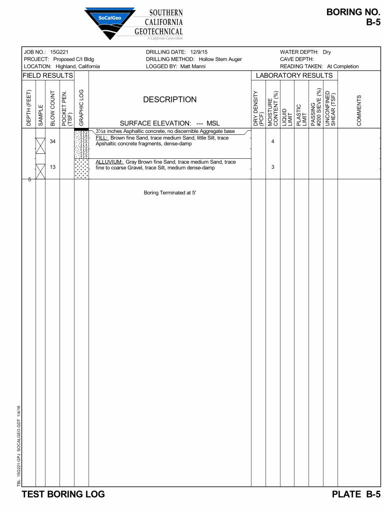
34
13
3½± inches Asphaltic concrete, no discernible Aggregate baseFILL: Brown fine Sand, trace medium Sand, little Silt, traceApshaltic concrete fragments, dense-damp
ALLUVIUM: Gray Brown fine Sand, trace medium Sand, tracefine to coarse Gravel, trace Silt, medium dense-damp
Boring Terminated at 5'
4
3
JOB NO.: 15G221PROJECT: Proposed C/I BldgLOCATION: Highland, California
BORING NO.B-5
PLATE B-5
DRILLING DATE: 12/9/15DRILLING METHOD: Hollow Stem AugerLOGGED BY: Matt Manni
FIELD RESULTS LABORATORY RESULTS
CO
MM
EN
TS
SURFACE ELEVATION: --- MSL
WATER DEPTH: DryCAVE DEPTH:READING TAKEN: At Completion
5
GR
AP
HIC
LO
G
PA
SS
ING
#200
SIE
VE
(%
)
TEST BORING LOG
DESCRIPTION
PO
CK
ET
PE
N.
(TS
F)
UN
CO
NF
INE
DS
HE
AR
(T
SF
)
DR
Y D
EN
SIT
Y(P
CF
)
DE
PT
H (
FE
ET
)
MO
IST
UR
EC
ON
TE
NT
(%
)
LIQ
UID
LIM
IT
PLA
ST
ICLI
MIT
SA
MP
LE
BLO
W C
OU
NT
TB
L 1
5G
221.
GP
J S
OC
ALG
EO
.GD
T 1
/4/1
6

16
39
47
23
34
32
ALLUVIUM: Light Gray Brown fine Sand, trace medium Sand,trace fine to coarse Gravel, medium dense-damp
Light Gray Brown Gravelly fine to coarse Sand, occasionalCobbles, dense-dry to damp
Light Brown fine to medium Sand, little coarse Sand, trace fineGravel, trace Silt, medium dense-damp
@ 13½ to 20 feet, little fine to coarse Gravel, dense
Boring Terminated at 20'
3
2
2
3
4
4
JOB NO.: 15G221PROJECT: Proposed C/I BldgLOCATION: Highland, California
BORING NO.B-6
PLATE B-6
DRILLING DATE: 12/9/15DRILLING METHOD: Hollow Stem AugerLOGGED BY: Matt Manni
FIELD RESULTS LABORATORY RESULTS
CO
MM
EN
TS
SURFACE ELEVATION: --- MSL
WATER DEPTH: DryCAVE DEPTH: 6 feetREADING TAKEN: At Completion
5
10
15
20
GR
AP
HIC
LO
G
PA
SS
ING
#200
SIE
VE
(%
)
TEST BORING LOG
DESCRIPTION
PO
CK
ET
PE
N.
(TS
F)
UN
CO
NF
INE
DS
HE
AR
(T
SF
)
DR
Y D
EN
SIT
Y(P
CF
)
DE
PT
H (
FE
ET
)
MO
IST
UR
EC
ON
TE
NT
(%
)
LIQ
UID
LIM
IT
PLA
ST
ICLI
MIT
SA
MP
LE
BLO
W C
OU
NT
TB
L 1
5G
221.
GP
J S
OC
ALG
EO
.GD
T 1
/4/1
6

PLATE B-7
TRENCH NO.
T-1
DE
PT
H
SA
MP
LE
DR
Y D
EN
SIT
Y
(P
CF
)
MO
IS
TU
RE
(%
)
EARTH MATERIALS
DESCRIPTION
GRAPHIC REPRESENTATION
5
10
15
JOB NO.: 15G221-1
PROJECT: C/I Building
LOCATION: Highland, CA
DATE: 12-10-2015
SCALE: 1" = 5'
TRENCH LOG
KEY TO SAMPLE TYPES:
B - BULK SAMPLE (DISTURBED)
R - RING SAMPLE 2-1/2" DIAMETER
(RELATIVELY UNDISTURBED)
A: FILL: Gray Silty fine to coarse Sand, some fine Gravel, trace Asphaltic
concrete and Metal fragments, medium dense - damp
B: FILL: Brown fine Sand, trace coarse Sand, trace Silt, medium dense -
damp
C: ALLUVIUM: Light Brown fine to medium Sand, trace fine to coarse
Gravel, occasional Cobbles, medium dense - dry to damp
D: ALLUVIUM: Light Brown fine to coarse Gravelly Sand, occasional
Cobbles, medium dense - dry to damp
E: ALLUVIUM: Brown fine to coarse Sand, some fine to coarse Gravel,
occasional Cobbles and Boulders, medium dense - dry to damp
F: ALLUVIUM: Brown Gravelly fine to coarse Sand, occasional Cobbles,
medium dense - dry to damp
N 90 W
WATER DEPTH: Dry
SEEPAGE DEPTH: Dry
READINGS TAKEN: At Completion
EQUIPMENT USED: Backhoe
LOGGED BY: Daryl Kas
ORIENTATION: N 90 W
TOP OF TRENCH ELEVATION:
C
B
A
D
E
F
Trench Terminated @ 10 feet
b 3
3
1
2
2
b
b
b
b

PLATE B-8
TRENCH NO.
T-2
DE
PT
H
SA
MP
LE
DR
Y D
EN
SIT
Y
(P
CF
)
MO
IS
TU
RE
(%
)
EARTH MATERIALS
DESCRIPTION
GRAPHIC REPRESENTATION
5
10
15
SCALE: 1" = 5'
TRENCH LOG
KEY TO SAMPLE TYPES:
B - BULK SAMPLE (DISTURBED)
R - RING SAMPLE 2-1/2" DIAMETER
(RELATIVELY UNDISTURBED)
A: FILL: Brown Silty fine Sand, medium dense - dry to damp
B: FILL: Gray Brown fine Sand, trace Silt, medium dense - dry to damp
C: ALLUVIUM: Light Gray fine to medium Sand, trace coarse Sand,
medium dense - dry to damp
D: ALLUVIUM: Brown fine to coarse Sandy Gravel, occasional Cobbles,
medium dense - dry to damp
E: ALLUVIUM: Light Brown fine to medium Sand, trace coarse Sand,
occasional Cobbles, medium dense - dry to damp
N 90 E
A
B
Trench Terminated @ 8
1
2
feet
JOB NO.: 15G221-1
PROJECT: C/I Building
LOCATION: Highland, CA
DATE: 12-10-2015
EQUIPMENT USED: Backhoe
LOGGED BY: Daryl Kas
ORIENTATION: N 90 E
TOP OF TRENCH ELEVATION:
WATER DEPTH: Dry
SEEPAGE DEPTH: Dry
READINGS TAKEN: At Completion
C
E
D
2b
2b
2b
2b
2b

PLATE B-9
TRENCH NO.
T-3
DE
PT
H
SA
MP
LE
DR
Y D
EN
SIT
Y
(P
CF
)
MO
IS
TU
RE
(%
)
EARTH MATERIALS
DESCRIPTION
GRAPHIC REPRESENTATION
5
10
15
SCALE: 1" = 5'
TRENCH LOG
KEY TO SAMPLE TYPES:
B - BULK SAMPLE (DISTURBED)
R - RING SAMPLE 2-1/2" DIAMETER
(RELATIVELY UNDISTURBED)
A: FILL: Brown Silty fine Sand, trace medium Sand, medium dense - dry
to damp
B: FILL: Gray Brown fine to medium Sand, trace Silt, trace fine Gravel,
medium dense - damp
C: FILL: Gray Brown Silty fine Sand, trace medium Sand, trace Glass
fragments, medium dense - dry to damp
D: ALLUVIUM: Light Brown fine to medium Sand, some coarse Sand,
occasional Cobbles, medium dense - dry to damp
E: ALLUVIUM: Brown fine to coarse Sandy Gravel, extensive Cobbles
and Boulders, dense - dry to damp
F: ALLUVIUM: Brown Gravelly fine to coarse Sand, medium dense - dry
to damp
N 0 E
A
Trench Terminated @ 9
1
2
feet
D
C
JOB NO.: 15G221-1
PROJECT: C/I Building
LOCATION: Highland, CA
DATE: 12-10-2015
EQUIPMENT USED: Backhoe
LOGGED BY: Daryl Kas
ORIENTATION: N 0 E
TOP OF TRENCH ELEVATION:
WATER DEPTH: Dry
SEEPAGE DEPTH: Dry
READINGS TAKEN: At Completion
B
E
F
2b
4b
1b
2b
2b

PLATE B-10
TRENCH NO.
T-4
DE
PT
H
SA
MP
LE
DR
Y D
EN
SIT
Y
(P
CF
)
MO
IS
TU
RE
(%
)
EARTH MATERIALS
DESCRIPTION
GRAPHIC REPRESENTATION
5
10
15
SCALE: 1" = 5'
TRENCH LOG
KEY TO SAMPLE TYPES:
B - BULK SAMPLE (DISTURBED)
R - RING SAMPLE 2-1/2" DIAMETER
(RELATIVELY UNDISTURBED)
A: FILL: Brown Silty fine Sand, trace medium Sand, medium dense -
damp to moist
B: FILL: Gray Brown fine Sand, trace Silt, medium dense - dry to damp
C: ALLUVIUM: Light Gray fine to medium Sand, trace coarse Sand, trace
fine Gravel, medium dense - dry to damp
D: ALLUVIUM: Brown fine to coarse Sandy Gravel, extensive Cobbles
and Boulders, dense - dry to damp
F: ALLUVIUM: Light Brown fine to medium Sand, trace coarse Sand,
trace fine Gravel, medium dense - dry to damp
S 0 E
A
Trench Terminated @ 9 feet
C
JOB NO.: 15G221-1
PROJECT: C/I Building
LOCATION: Highland, CA
DATE: 12-10-2015
EQUIPMENT USED: Backhoe
LOGGED BY: Daryl Kas
ORIENTATION: S 0 E
TOP OF TRENCH ELEVATION:
WATER DEPTH: Dry
SEEPAGE DEPTH: Dry
READINGS TAKEN: At Completion
B
D
E
2b
2b
2b
2b


Classification: Light Gray fine to coarse Sand, little fine to coarse Gravel
Boring Number: B-1 Initial Moisture Content (%) 1
Sample Number: --- Final Moisture Content (%) 13
Depth (ft) 3 to 4 Initial Dry Density (pcf) 116.2
Specimen Diameter (in) 2.4 Final Dry Density (pcf) 123.7
Specimen Thickness (in) 1.0 Percent Collapse (%) 1.14
Proposed C/I BldgHighland, CaliforniaProject No. 15G221
PLATE C- 1
-2
0
2
4
6
8
10
12
14
16
180.1 1 10 100
Co
nso
lid
ati
on
Str
ain
(%)
Load (ksf)
Consolidation/Collapse Test Results
Water Addedat 1600 psf
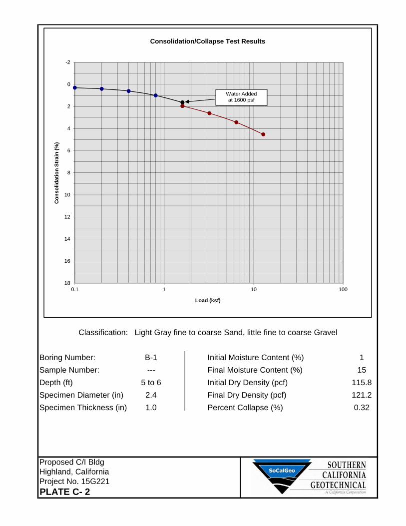
Classification: Light Gray fine to coarse Sand, little fine to coarse Gravel
Boring Number: B-1 Initial Moisture Content (%) 1
Sample Number: --- Final Moisture Content (%) 15
Depth (ft) 5 to 6 Initial Dry Density (pcf) 115.8
Specimen Diameter (in) 2.4 Final Dry Density (pcf) 121.2
Specimen Thickness (in) 1.0 Percent Collapse (%) 0.32
Proposed C/I BldgHighland, CaliforniaProject No. 15G221
PLATE C- 2
-2
0
2
4
6
8
10
12
14
16
180.1 1 10 100
Co
nso
lid
ati
on
Str
ain
(%)
Load (ksf)
Consolidation/Collapse Test Results
Water Addedat 1600 psf

Classification: Light Brown fine to coarse Sand, trace fine to coarse Gravel, trace Silt
Boring Number: B-1 Initial Moisture Content (%) 2
Sample Number: --- Final Moisture Content (%) 16
Depth (ft) 7 to 8 Initial Dry Density (pcf) 112.2
Specimen Diameter (in) 2.4 Final Dry Density (pcf) 118.3
Specimen Thickness (in) 1.0 Percent Collapse (%) 1.15
Proposed C/I BldgHighland, CaliforniaProject No. 15G221
PLATE C- 3
-2
0
2
4
6
8
10
12
14
16
180.1 1 10 100
Co
nso
lid
ati
on
Str
ain
(%)
Load (ksf)
Consolidation/Collapse Test Results
Water Addedat 1600 psf

Classification: Light Brown fine to coarse Sand, trace fine to coarse Gravel, trace Silt
Boring Number: B-1 Initial Moisture Content (%) 2
Sample Number: --- Final Moisture Content (%) 15
Depth (ft) 9 to 10 Initial Dry Density (pcf) 119.7
Specimen Diameter (in) 2.4 Final Dry Density (pcf) 124.4
Specimen Thickness (in) 1.0 Percent Collapse (%) 1.00
Proposed C/I BldgHighland, CaliforniaProject No. 15G221
PLATE C- 4
-2
0
2
4
6
8
10
12
14
16
180.1 1 10 100
Co
nso
lid
ati
on
Str
ain
(%)
Load (ksf)
Consolidation/Collapse Test Results
Water Addedat 1600 psf

Proposed C/I BldgHighland, CaliforniaProject No. 15G221
PLATE C-5
108
110
112
114
116
118
120
122
124
126
128
130
132
134
4 6 8 10 12 14 16 18
Dry
Den
sit
y(l
bs/f
t3)
Moisture Content (%)
Moisture/Density RelationshipASTM D-1557
Soil ID Number B-6 @ 0 to 5'Optimum Moisture (%) 8
Maximum Dry Density (pcf) 128
Soil
Classification Brown fine to medium Sand,some Silt
Zero Air Voids Curve:Specific Gravity = 2.7

Grading Guide Specifications Page 1 GRADING GUIDE SPECIFICATIONS These grading guide specifications are intended to provide typical procedures for grading operations. They are intended to supplement the recommendations contained in the geotechnical investigation report for this project. Should the recommendations in the geotechnical investigation report conflict with the grading guide specifications, the more site specific recommendations in the geotechnical investigation report will govern. General
• The Earthwork Contractor is responsible for the satisfactory completion of all earthwork in accordance with the plans and geotechnical reports, and in accordance with city, county, and applicable building codes.
• The Geotechnical Engineer is the representative of the Owner/Builder for the purpose of
implementing the report recommendations and guidelines. These duties are not intended to relieve the Earthwork Contractor of any responsibility to perform in a workman-like manner, nor is the Geotechnical Engineer to direct the grading equipment or personnel employed by the Contractor.
• The Earthwork Contractor is required to notify the Geotechnical Engineer of the anticipated
work and schedule so that testing and inspections can be provided. If necessary, work may be stopped and redone if personnel have not been scheduled in advance.
• The Earthwork Contractor is required to have suitable and sufficient equipment on the job-
site to process, moisture condition, mix and compact the amount of fill being placed to the approved compaction. In addition, suitable support equipment should be available to conform with recommendations and guidelines in this report.
• Canyon cleanouts, overexcavation areas, processed ground to receive fill, key excavations,
subdrains and benches should be observed by the Geotechnical Engineer prior to placement of any fill. It is the Earthwork Contractor's responsibility to notify the Geotechnical Engineer of areas that are ready for inspection.
• Excavation, filling, and subgrade preparation should be performed in a manner and
sequence that will provide drainage at all times and proper control of erosion. Precipitation, springs, and seepage water encountered shall be pumped or drained to provide a suitable working surface. The Geotechnical Engineer must be informed of springs or water seepage encountered during grading or foundation construction for possible revision to the recommended construction procedures and/or installation of subdrains.
Site Preparation
• The Earthwork Contractor is responsible for all clearing, grubbing, stripping and site preparation for the project in accordance with the recommendations of the Geotechnical Engineer.
• If any materials or areas are encountered by the Earthwork Contractor which are suspected
of having toxic or environmentally sensitive contamination, the Geotechnical Engineer and Owner/Builder should be notified immediately.

Grading Guide Specifications Page 2
• Major vegetation should be stripped and disposed of off-site. This includes trees, brush, heavy grasses and any materials considered unsuitable by the Geotechnical Engineer.
• Underground structures such as basements, cesspools or septic disposal systems, mining
shafts, tunnels, wells and pipelines should be removed under the inspection of the Geotechnical Engineer and recommendations provided by the Geotechnical Engineer and/or city, county or state agencies. If such structures are known or found, the Geotechnical Engineer should be notified as soon as possible so that recommendations can be formulated.
• Any topsoil, slopewash, colluvium, alluvium and rock materials which are considered
unsuitable by the Geotechnical Engineer should be removed prior to fill placement.
• Remaining voids created during site clearing caused by removal of trees, foundations basements, irrigation facilities, etc., should be excavated and filled with compacted fill.
• Subsequent to clearing and removals, areas to receive fill should be scarified to a depth of
10 to 12 inches, moisture conditioned and compacted • The moisture condition of the processed ground should be at or slightly above the optimum
moisture content as determined by the Geotechnical Engineer. Depending upon field conditions, this may require air drying or watering together with mixing and/or discing.
Compacted Fills
• Soil materials imported to or excavated on the property may be utilized in the fill, provided each material has been determined to be suitable in the opinion of the Geotechnical Engineer. Unless otherwise approved by the Geotechnical Engineer, all fill materials shall be free of deleterious, organic, or frozen matter, shall contain no chemicals that may result in the material being classified as “contaminated,” and shall be very low to non-expansive with a maximum expansion index (EI) of 50. The top 12 inches of the compacted fill should have a maximum particle size of 3 inches, and all underlying compacted fill material a maximum 6-inch particle size, except as noted below.
• All soils should be evaluated and tested by the Geotechnical Engineer. Materials with high
expansion potential, low strength, poor gradation or containing organic materials may require removal from the site or selective placement and/or mixing to the satisfaction of the Geotechnical Engineer.
• Rock fragments or rocks less than 6 inches in their largest dimensions, or as otherwise
determined by the Geotechnical Engineer, may be used in compacted fill, provided the distribution and placement is satisfactory in the opinion of the Geotechnical Engineer.
• Rock fragments or rocks greater than 12 inches should be taken off-site or placed in
accordance with recommendations and in areas designated as suitable by the Geotechnical Engineer. These materials should be placed in accordance with Plate D-8 of these Grading Guide Specifications and in accordance with the following recommendations:
• Rocks 12 inches or more in diameter should be placed in rows at least 15 feet apart, 15
feet from the edge of the fill, and 10 feet or more below subgrade. Spaces should be left between each rock fragment to provide for placement and compaction of soil around the fragments.
• Fill materials consisting of soil meeting the minimum moisture content requirements and
free of oversize material should be placed between and over the rows of rock or

Grading Guide Specifications Page 3
concrete. Ample water and compactive effort should be applied to the fill materials as they are placed in order that all of the voids between each of the fragments are filled and compacted to the specified density.
• Subsequent rows of rocks should be placed such that they are not directly above a row
placed in the previous lift of fill. A minimum 5-foot offset between rows is recommended.
• To facilitate future trenching, oversized material should not be placed within the range
of foundation excavations, future utilities or other underground construction unless specifically approved by the soil engineer and the developer/owner representative.
• Fill materials approved by the Geotechnical Engineer should be placed in areas previously
prepared to receive fill and in evenly placed, near horizontal layers at about 6 to 8 inches in loose thickness, or as otherwise determined by the Geotechnical Engineer for the project.
• Each layer should be moisture conditioned to optimum moisture content, or slightly above,
as directed by the Geotechnical Engineer. After proper mixing and/or drying, to evenly distribute the moisture, the layers should be compacted to at least 90 percent of the maximum dry density in compliance with ASTM D-1557-78 unless otherwise indicated.
• Density and moisture content testing should be performed by the Geotechnical Engineer at
random intervals and locations as determined by the Geotechnical Engineer. These tests are intended as an aid to the Earthwork Contractor, so he can evaluate his workmanship, equipment effectiveness and site conditions. The Earthwork Contractor is responsible for compaction as required by the Geotechnical Report(s) and governmental agencies.
• Fill areas unused for a period of time may require moisture conditioning, processing and recompaction prior to the start of additional filling. The Earthwork Contractor should notify the Geotechnical Engineer of his intent so that an evaluation can be made.
• Fill placed on ground sloping at a 5-to-1 inclination (horizontal-to-vertical) or steeper should
be benched into bedrock or other suitable materials, as directed by the Geotechnical Engineer. Typical details of benching are illustrated on Plates D-2, D-4, and D-5.
• Cut/fill transition lots should have the cut portion overexcavated to a depth of at least 3 feet
and rebuilt with fill (see Plate D-1), as determined by the Geotechnical Engineer.
• All cut lots should be inspected by the Geotechnical Engineer for fracturing and other bedrock conditions. If necessary, the pads should be overexcavated to a depth of 3 feet and rebuilt with a uniform, more cohesive soil type to impede moisture penetration.
• Cut portions of pad areas above buttresses or stabilizations should be overexcavated to a
depth of 3 feet and rebuilt with uniform, more cohesive compacted fill to impede moisture penetration.
• Non-structural fill adjacent to structural fill should typically be placed in unison to provide
lateral support. Backfill along walls must be placed and compacted with care to ensure that excessive unbalanced lateral pressures do not develop. The type of fill material placed adjacent to below grade walls must be properly tested and approved by the Geotechnical Engineer with consideration of the lateral earth pressure used in the design.

Grading Guide Specifications Page 4 Foundations
• The foundation influence zone is defined as extending one foot horizontally from the outside edge of a footing, and proceeding downward at a ½ horizontal to 1 vertical (0.5:1) inclination.
• Where overexcavation beneath a footing subgrade is necessary, it should be conducted so
as to encompass the entire foundation influence zone, as described above.
• Compacted fill adjacent to exterior footings should extend at least 12 inches above foundation bearing grade. Compacted fill within the interior of structures should extend to the floor subgrade elevation.
Fill Slopes
• The placement and compaction of fill described above applies to all fill slopes. Slope compaction should be accomplished by overfilling the slope, adequately compacting the fill in even layers, including the overfilled zone and cutting the slope back to expose the compacted core
• Slope compaction may also be achieved by backrolling the slope adequately every 2 to 4
vertical feet during the filling process as well as requiring the earth moving and compaction equipment to work close to the top of the slope. Upon completion of slope construction, the slope face should be compacted with a sheepsfoot connected to a sideboom and then grid rolled. This method of slope compaction should only be used if approved by the Geotechnical Engineer.
• Sandy soils lacking in adequate cohesion may be unstable for a finished slope condition and
therefore should not be placed within 15 horizontal feet of the slope face.
• All fill slopes should be keyed into bedrock or other suitable material. Fill keys should be at least 15 feet wide and inclined at 2 percent into the slope. For slopes higher than 30 feet, the fill key width should be equal to one-half the height of the slope (see Plate D-5).
• All fill keys should be cleared of loose slough material prior to geotechnical inspection and
should be approved by the Geotechnical Engineer and governmental agencies prior to filling.
• The cut portion of fill over cut slopes should be made first and inspected by the Geotechnical Engineer for possible stabilization requirements. The fill portion should be adequately keyed through all surficial soils and into bedrock or suitable material. Soils should be removed from the transition zone between the cut and fill portions (see Plate D-2).
Cut Slopes
• All cut slopes should be inspected by the Geotechnical Engineer to determine the need for stabilization. The Earthwork Contractor should notify the Geotechnical Engineer when slope cutting is in progress at intervals of 10 vertical feet. Failure to notify may result in a delay in recommendations.
• Cut slopes exposing loose, cohesionless sands should be reported to the Geotechnical
Engineer for possible stabilization recommendations.
• All stabilization excavations should be cleared of loose slough material prior to geotechnical inspection. Stakes should be provided by the Civil Engineer to verify the location and dimensions of the key. A typical stabilization fill detail is shown on Plate D-5.

Grading Guide Specifications Page 5
• Stabilization key excavations should be provided with subdrains. Typical subdrain details are shown on Plates D-6.
Subdrains
• Subdrains may be required in canyons and swales where fill placement is proposed. Typical subdrain details for canyons are shown on Plate D-3. Subdrains should be installed after approval of removals and before filling, as determined by the Soils Engineer.
• Plastic pipe may be used for subdrains provided it is Schedule 40 or SDR 35 or equivalent.
Pipe should be protected against breakage, typically by placement in a square-cut (backhoe) trench or as recommended by the manufacturer.
• Filter material for subdrains should conform to CALTRANS Specification 68-1.025 or as
approved by the Geotechnical Engineer for the specific site conditions. Clean ¾-inch crushed rock may be used provided it is wrapped in an acceptable filter cloth and approved by the Geotechnical Engineer. Pipe diameters should be 6 inches for runs up to 500 feet and 8 inches for the downstream continuations of longer runs. Four-inch diameter pipe may be used in buttress and stabilization fills.

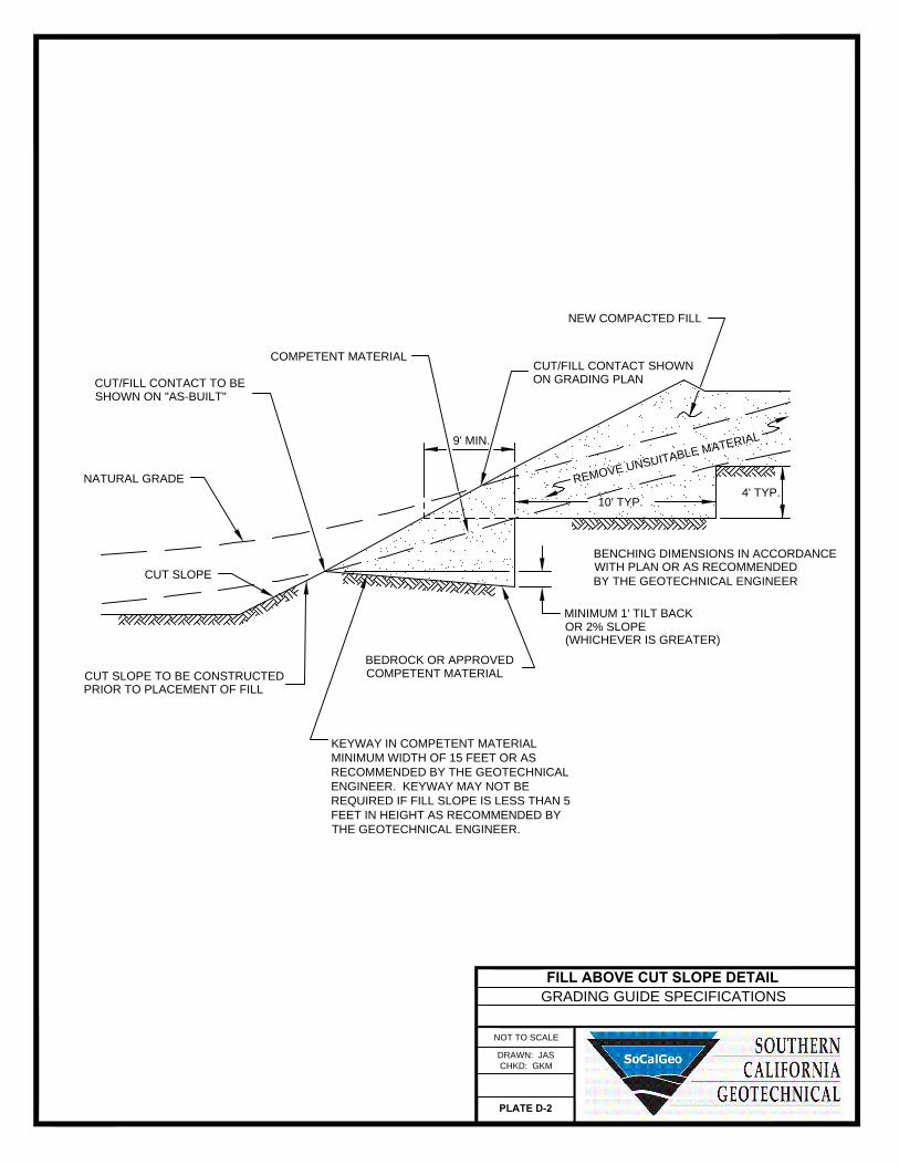
GRADING GUIDE SPECIFICATIONS
NOT TO SCALE
DRAWN: JAS
CHKD: GKM
PLATE D-2
FILL ABOVE CUT SLOPE DETAIL
9' MIN.
4' TYP.
MINIMUM 1' TILT BACK
OR 2% SLOPE
(WHICHEVER IS GREATER)
R
E
M
O
V
E
U
N
S
U
IT
A
B
L
E
M
A
T
E
R
IA
L
BENCHING DIMENSIONS IN ACCORDANCE
WITH PLAN OR AS RECOMMENDED
BY THE GEOTECHNICAL ENGINEER
CUT SLOPE TO BE CONSTRUCTED
PRIOR TO PLACEMENT OF FILL
BEDROCK OR APPROVED
COMPETENT MATERIAL
CUT SLOPE
NATURAL GRADE
CUT/FILL CONTACT TO BE
SHOWN ON "AS-BUILT"
COMPETENT MATERIAL
CUT/FILL CONTACT SHOWN
ON GRADING PLAN
NEW COMPACTED FILL
10' TYP.
KEYWAY IN COMPETENT MATERIAL
MINIMUM WIDTH OF 15 FEET OR AS
RECOMMENDED BY THE GEOTECHNICAL
ENGINEER. KEYWAY MAY NOT BE
REQUIRED IF FILL SLOPE IS LESS THAN 5
FEET IN HEIGHT AS RECOMMENDED BY
THE GEOTECHNICAL ENGINEER.
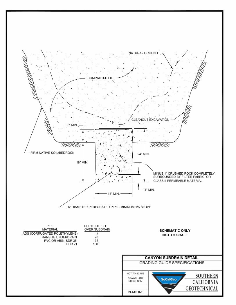

GRADING GUIDE SPECIFICATIONS
NOT TO SCALE
DRAWN: JAS
CHKD: GKM
PLATE D-4
FILL ABOVE NATURAL SLOPE DETAIL
10' TYP.
4' TYP.
(WHICHEVER IS GREATER)
OR 2% SLOPE
MINIMUM 1' TILT BACK
R
E
M
O
V
E
U
N
S
U
IT
A
B
L
E
M
A
T
E
R
IA
L
NEW COMPACTED FILL
COMPETENT MATERIAL
KEYWAY IN COMPETENT MATERIAL.
RECOMMENDED BY THE GEOTECHNIAL
ENGINEER. KEYWAY MAY NOT BE REQUIRED
IF FILL SLOPE IS LESS THAN 5' IN HEIGHT
AS RECOMMENDED BY THE GEOTECHNICAL
ENGINEER.
2' MINIMUM
KEY DEPTH
OVERFILL REQUIREMENTS
PER GRADING GUIDE SPECIFICATIONS
TOE OF SLOPE SHOWN
ON GRADING PLAN
BACKCUT - VARIES
PLACE COMPACTED BACKFILL
TO ORIGINAL GRADE
PROJECT SLOPE GRADIENT
(1:1 MAX.)
NOTE:
BENCHING SHALL BE REQUIRED
WHEN NATURAL SLOPES ARE
EQUAL TO OR STEEPER THAN 5:1
OR WHEN RECOMMENDED BY
THE GEOTECHNICAL ENGINEER.
FINISHED SLOPE FACE
MINIMUM WIDTH OF 15 FEET OR AS
BENCHING DIMENSIONS IN ACCORDANCE
WITH PLAN OR AS RECOMMENDED
BY THE GEOTECHNICAL ENGINEER

GRADING GUIDE SPECIFICATIONS
NOT TO SCALE
DRAWN: JAS
CHKD: GKM
PLATE D-5
STABILIZATION FILL DETAIL
FACE OF FINISHED SLOPE
COMPACTED FILL
MINIMUM 1' TILT BACK
OR 2% SLOPE
(WHICHEVER IS GREATER)
10' TYP.
2' MINIMUM
KEY DEPTH
3' TYPICAL
BLANKET FILL IF RECOMMENDED
BY THE GEOTECHNICAL ENGINEER
COMPETENT MATERIAL ACCEPTABLE
TO THE SOIL ENGINEER
KEYWAY WIDTH, AS SPECIFIED
BY THE GEOTECHNICAL ENGINEER
TOP WIDTH OF FILL
AS SPECIFIED BY THE
GEOTECHNICAL ENGINEER
BENCHING DIMENSIONS IN ACCORDANCE
WITH PLAN OR AS RECOMMENDED
BY THE GEOTECHNICAL ENGINEER
4' TYP.


PROPOSED COMMERCIAL/INDUSTRIAL BUILDING
DRAWN: JL
CHKD: JAS
SCG PROJECT
15G221-1
PLATE E-1
SEISMIC DESIGN PARAMETERS
HIGHLAND, CALIFORNIA
SOURCE: U.S. GEOLOGICAL SURVEY (USGS)
<http://geohazards.usgs.gov/designmaps/us/application.php>