geotechnical engineering study proposed new …
TRANSCRIPT

GEOTECHNICAL ENGINEERING STUDY
PROPOSED NEW BUILDING
PORT ARTHUR, TEXAS
Prepared for:
Chica & Associates, Inc.
505 Orleans Street, Suite 106
Beaumont, Texas 77701
Prepared by:
Tolunay-Wong Engineers, Inc.
2455 West Cardinal Drive, Suite A
Beaumont, Texas 77705
July 31, 2013
Project No. 13.23.174 / Report No. 60989
TWE Project No. 13.23.174 i Report No. 60989
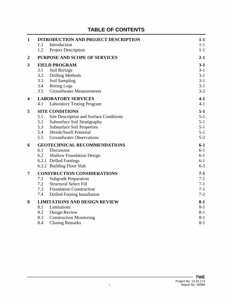
TABLE OF CONTENTS
1 INTRODUCTION AND PROJECT DESCRIPTION 1-1 1.1 Introduction 1-1 1.2 Project Description 1-1
2 PURPOSE AND SCOPE OF SERVICES 2-1
3 FIELD PROGRAM 3-1 3.1 Soil Borings 3-1 3.2 Drilling Methods 3-1 3.3 Soil Sampling 3-1 3.4 Boring Logs 3-1
3.5 Groundwater Measurements 3-2
4 LABORATORY SERVICES 4-1 4.1 Laboratory Testing Program 4-1
5 SITE CONDITIONS 5-1 5.1 Site Description and Surface Conditions 5-1 5.2 Subsurface Soil Stratigraphy 5-1
5.3 Subsurface Soil Properties 5-1 5.4 Shrink/Swell Potential 5-1
5.5 Groundwater Observations 5-2
6 GEOTECHNICAL RECOMMENDATIONS 6-1 6.1 Discussion 6-1
6.2 Shallow Foundation Design 6-1 6.2.1 Drilled Footings 6-1
6.2.2 Building Floor Slab 6-3
7 CONSTRUCTION CONSIDERATIONS 7-1 7.1 Subgrade Preparation 7-1 7.2 Structural Select Fill 7-1 7.3 Foundation Construction 7-1
7.4 Drilled Footing Installation 7-2
8 LIMITATIONS AND DESIGN REVIEW 8-1 8.1 Limitations 8-1 8.2 Design Review 8-1 8.3 Construction Monitoring 8-1
8.4 Closing Remarks 8-1
TWE Project No. 13.23.174 ii Report No. 60989
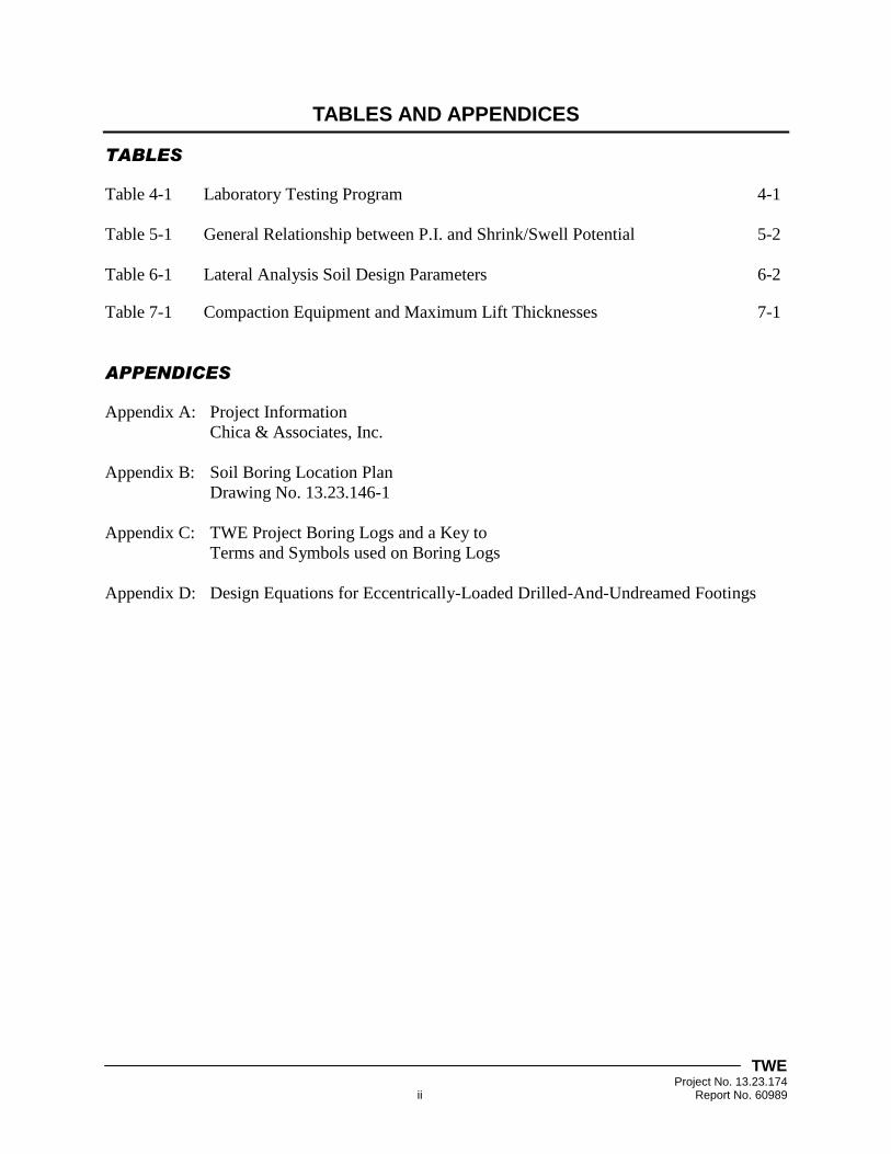
TABLES AND APPENDICES
TABLES
Table 4-1 Laboratory Testing Program 4-1
Table 5-1 General Relationship between P.I. and Shrink/Swell Potential 5-2
Table 6-1 Lateral Analysis Soil Design Parameters 6-2
Table 7-1 Compaction Equipment and Maximum Lift Thicknesses 7-1
APPENDICES
Appendix A: Project Information
Chica & Associates, Inc.
Appendix B: Soil Boring Location Plan
Drawing No. 13.23.146-1
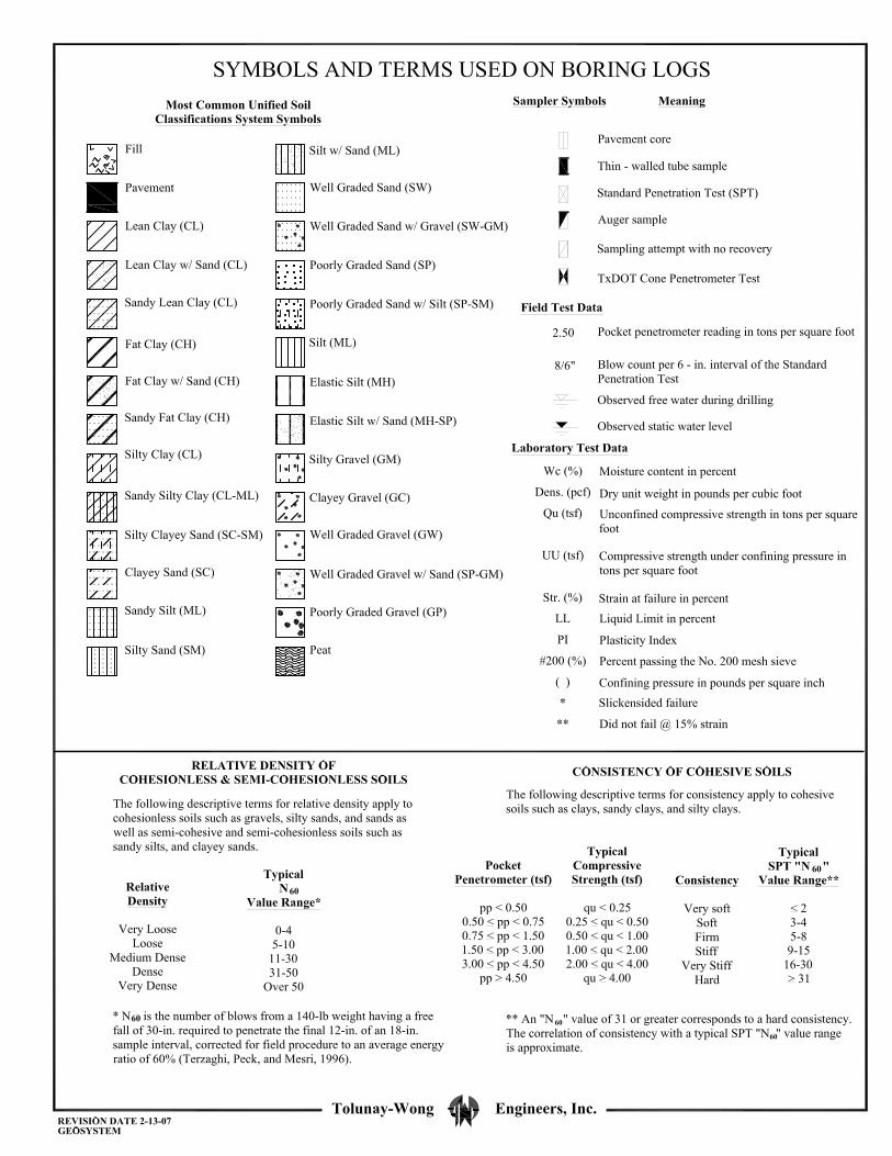
Appendix C: TWE Project Boring Logs and a Key to
Terms and Symbols used on Boring Logs
Appendix D: Design Equations for Eccentrically-Loaded Drilled-And-Undreamed Footings

TWE Project No. 13.23.174 1-1 Report No. 60989
1 INTRODUCTION AND PROJECT DESCRIPTION
1.1 Introduction
This report presents the results of our geotechnical engineering study performed for the proposed
new building to be constructed in Port Arthur, Texas. The building location is presented on the
drawing provided by the Client in Appendix A. Our geotechnical engineering study was
performed in general accordance with TWE Proposal No. P13-B105 (Revision 2) dated June 9,
2013 and authorized by Andy Chica of Chica & Associates, Inc. (Client) on June 9, 2013.
1.2 Project Description
The project includes the construction a new building near the intersection of Shreveport Avenue
and 4th
Street in Port Arthur, Texas. The building is approximately 14,000-ft2 in size. Project
information provided by the Client is presented in Appendix A.
TWE Project No. 13.23.174 2-1 Report No. 60989
2 PURPOSE AND SCOPE OF SERVICES
The purposes of our geotechnical engineering study were to investigate the soil and groundwater
conditions within the project site and to assist our Client in the design and construction of
foundations for the proposed new building.
Our scope of services for the project consisted of:
1. Drilling one (1) soil boring within the building footprint to evaluate
subsurface stratigraphy and groundwater conditions;
2. Performing geotechnical laboratory tests on recovered soil samples to
evaluate the physical and engineering properties of the strata encountered;
3. Providing geotechnical design recommendations for suitable shallow
foundations to support the proposed new building; and,
4. Providing geotechnical construction recommendations including site and
subgrade preparation, excavation considerations, fill and backfill
requirements, compaction requirements, foundation installation and overall
quality control monitoring, testing and inspection services.
Our scope of services did not include any environmental assessments for the presence or absence
of wetlands or of hazardous or toxic materials within or on the soil, air or water at the project
site. Any statements in this report or on the boring logs regarding odors, colors, unusual or
suspicious items and conditions are strictly for the information of the Client. A geological fault
study was also beyond the scope of our geotechnical engineering study.

TWE Project No. 13.23.174 3-1 Report No. 60989
3 FIELD PROGRAM
3.1 Soil Borings
As requested, TWE conducted an exploration of subsurface soil and groundwater conditions at
the project site on July 19, 2013 by drilling, logging and sampling one (1) soil boring to a depth
of 30-ft below ground surface. Our geotechnician coordinated the field activities, logged the
boreholes and obtained groundwater level measurements during drilling and sampling. The soil
boring locations are presented on Drawing No. 13.23.174-1 in Appendix B of this report.
3.2 Drilling Methods
Field operations were performed in general accordance with Standard Practice for Soil
Investigation and Sampling by Auger Borings [American Society for Testing and Materials
(ASTM) D 1452]. The soil borings were drilled using a truck-mounted drilling rig equipped with
a rotary head. The boreholes were advanced using dry-auger drilling methods. Samples were
obtained continuously at intervals of 2-ft from existing ground surface to a depth of 12-ft, at 13-
ft to 15-ft and at 5-ft depth intervals thereafter until the boring completion depth of 30-ft was
reached.
3.3 Soil Sampling
Fine-grained, cohesive soil samples were recovered from the soil borings by hydraulically
pushing a 3-in diameter, thin-walled Shelby tube a distance of about 24-in. The field sampling
procedures were conducted in general accordance with the Standard Practice for Thin-Walled
Tube Sampling of Soils (ASTM D 1587). Our geotechnician visually classified the recovered soils
and obtained a field strength measurement of the soils using a calibrated pocket penetrometer. A
factor of 0.67 is typically applied to the penetrometer measurement to estimate the undrained
shear strength of the Gulf Coast cohesive soils. The samples were extruded in the field, wrapped
in foil, placed in moisture sealed plastic bags and protected from disturbance prior to transport to
the laboratory. The recovered soil sample depths and pocket penetrometer measurements are
presented on the boring logs in Appendix C.
3.4 Boring Logs
Our interpretations of general subsurface soil and groundwater conditions at the boring locations
are included on the project boring logs. The interpretations of the soil types throughout the
boring depths and the locations of strata changes were based on visual classifications during field
sampling and laboratory testing using Standard Practice for Classification of Soils for
Engineering Purposes (Unified Soil Classification System) [ASTM D 2487] and Standard
Practice for Description and Identification of Soils (Visual-Manual Procedure) [ASTM D 2488].
The boring logs include the type and interval depth for each sample along with the pocket
penetrometer readings and blow count values for the recovered soils. The project boring logs
and a key to the terms and symbols used on boring logs are presented in Appendix C.
TWE Project No. 13.23.174 3-2 Report No. 60989
Coarse-grained, cohesionless and semi-cohesionless soil samples were collected with the
Standard Penetration Test (SPT) sampler driven 18-in by blows from a 140-lb hammer falling
30-in in accordance with the Standard Test Method for Standard Penetration Test (SPT) and
Spilt-Barrel Sampling of Soils (ASTM D 1586). The number of blows required to advance the
sampler three (3) consecutive 6-in depths are recorded for each corresponding sample on the
boring logs. The N-value, in blows per foot, is obtained from SPTs by adding the last two (2)
blow count numbers. The relative density of cohesionless and semi-cohesionless soils and the
consistency of cohesive soils can be inferred from the N-value. The samples obtained from the
split-barrel sampler were visually classified, placed in moisture sealed plastic bags and
transported to our laboratory. SPT sampling intervals and blow counts are presented on the
boring logs in Appendix C of this report.
3.5 Groundwater Measurements
Groundwater level measurements were attempted in the open boreholes during dry-auger
drilling. Water level readings were attempted when groundwater was first encountered and at
five (5) minute intervals over a fifteen (15) minute time period. The groundwater observations
are summarized in Section 5.4 of this report entitled “Groundwater Observations.”

TWE Project No. 13.23.174 4-1 Report No. 60989
4 LABORATORY SERVICES
A laboratory testing program was conducted on selected samples to assist in classification of the
soils encountered in the project borings and to evaluate the physical and engineering properties of
the strata encountered at the project site.
4.1 Laboratory Testing Program
Laboratory tests were performed in general accordance with ASTM International standards to
measure physical and engineering properties of the recovered samples. The types and brief
descriptions of the laboratory tests performed are presented below.
Table 4-1
Laboratory Testing Program
Test Description Test Method
Amount of Material in Soils Finer than No. 200 Sieve ASTM D 1140
Water (Moisture) Content of Soil ASTM D 2216
Unconsolidated-Undrained Triaxial Compression on Cohesive Soils ASTM D 2850
Liquid Limit, Plastic Limit and Plasticity Index of Soils ASTM D 4318
Dry Unit Weight --
Amount of Materials in Soils Finer than No. 200 (75-µm) Sieve (ASTM D 1140)
This test method determines the amount of materials in soils finer than the No. 200 (75-µm)
sieve by washing. The loss in weight resulting from the wash treatment is presented as a
percentage of the original sample and is reported as the percentage of silt and clay particles in the
sample.
Water (Moisture) Content of Soil by Mass (ASTM D 2216)
This test method determines water (moisture) content by mass of soil where the reduction in
mass by drying is due to loss of water. The water (moisture) content of soil, expressed as a
percentage, is defined as the ratio of the mass of water to the mass of soil solids. Moisture
content may provide an indication of cohesive soil shear strength and compressibility when
compared to Atterberg Limits.
Unconsolidated-Undrained Triaxial Compression Test on Cohesive Soils (ASTM D 2850)
This test method determines the strength and stress-strain relationships of a cylindrical specimen
of either undisturbed or remolded cohesive soil. Specimens are subjected to a confining fluid
pressure in a triaxial chamber. No drainage of the specimen is permitted during the test. The
specimen is sheared in compression without drainage at a constant rate of axial deformation
(strain controlled). The unconsolidated-undrained (UU) triaxial shear strength of cohesive soils
is applicable to situations where loads are assumed to take place so rapidly that there is
insufficient time for induced pore-water pressures to dissipate and drainage to occur during the
loading period.

TWE Project No. 13.23.174 4-2 Report No. 60989
Liquid Limit, Plastic Limit and Plasticity Index of Soils (ASTM D 4318)
This test method determines the liquid limit, plastic limit and the plasticity index of soils. These
tests, also known as Atterberg limits, are used from soil classification purposes. They also
provide an indication of the volume change potential of a soil when considered in conjunction
with the natural moisture content. The liquid limit and plastic limit establish boundaries of
consistency for plastic soils. The plasticity index is the difference between the liquid limit and
plastic limit.
Dry Unit Weight of Soils
This test method determines the weight per unit volume of soil, excluding water. Dry unit
weight is used to relate the compactness of soils to volume change and stress-strain tendencies of
soils when subjected to external loadings.
Soil properties including moisture content, unit weight, Atterberg limits, grain size distribution,
penetration resistance and compressive strength are presented on the project boring logs in
Appendix C.
TWE Project No. 13.23.174 5-1 Report No. 60989
5 SITE CONDITIONS
Our interpretations of soil and groundwater conditions within the project site are based on
information obtained at the soil boring locations only. This information has been used as the
basis for our conclusions and recommendations. Subsurface conditions may vary at areas not
explored by the soil borings. Significant variations at areas not explored by the soil borings will
require reevaluation of our recommendations.
5.1 Site Description and Surface Conditions
The project site is located at the intersection of Shreveport Avenue and 4th
Street in Port Arthur,
Texas. The surface conditions consisted of an open area with grass cover. Drainage appeared to
be adequate.
5.2 Subsurface Soil Stratigraphy
The generalized subsurface profile encountered in the project borings consists of primarily firm
to stiff cohesive clay from existing grade to the completion depths. Detailed descriptions of the
soils encountered are provided on the boring logs in Appendix C.
5.3 Subsurface Soil Properties
Results of Atterberg limit tests on selected cohesive soil samples from the project borings
indicated liquid limits (LL) ranging from 28 to 73 with corresponding plasticity indices (PI)
ranging from 11 to 57. In-situ moisture contents from test on selected samples ranged from 21%
to 31%. The amount of material passing the No. 200 sieve ranged from 81% to 91% within the
selected cohesive soil samples tested.
Pocket penetrometer readings taken on cohesive samples indicated approximate undrained shear
strengths ranging from 0.33-tsf to 0.83-tsf. Undrained shear strengths derived from laboratory
UU testing ranged from 0.37-tsf to 0.64-tsf within the selected cohesive samples tested with
corresponding total unit weights ranging from 118-pcf to 128-pcf. Based on the above undrained
shear strength data, the cohesive soils encountered in the project borings are considered to have
firm to stiff consistencies.
The above laboratory test results are tabulated at the recovered sample depths on the boring logs
in Appendix C of this report.
5.4 Shrink/Swell Potential
The tendency for a soil to shrink and swell with change in moisture content is a function of clay
content and type, which are generally reflected in soil consistency as defined by the Atterberg
Limits. A generalized relationship between shrink/swell potential and the soil plasticity index (P.I.)
is shown on the following page:
TWE Project No. 13.23.174 5-2 Report No. 60989
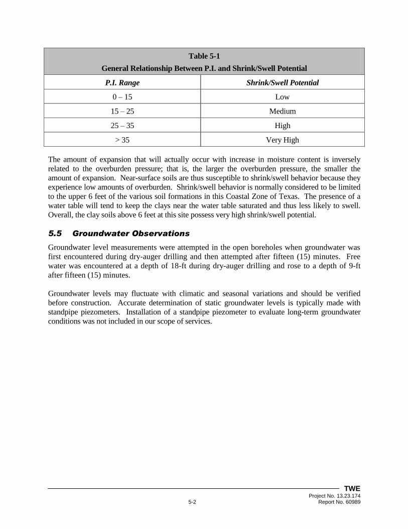
Table 5-1
General Relationship Between P.I. and Shrink/Swell Potential
P.I. Range Shrink/Swell Potential
0 – 15 Low
15 – 25 Medium
25 – 35 High
> 35 Very High
The amount of expansion that will actually occur with increase in moisture content is inversely
related to the overburden pressure; that is, the larger the overburden pressure, the smaller the
amount of expansion. Near-surface soils are thus susceptible to shrink/swell behavior because they
experience low amounts of overburden. Shrink/swell behavior is normally considered to be limited
to the upper 6 feet of the various soil formations in this Coastal Zone of Texas. The presence of a
water table will tend to keep the clays near the water table saturated and thus less likely to swell.
Overall, the clay soils above 6 feet at this site possess very high shrink/swell potential.
5.5 Groundwater Observations
Groundwater level measurements were attempted in the open boreholes when groundwater was
first encountered during dry-auger drilling and then attempted after fifteen (15) minutes. Free
water was encountered at a depth of 18-ft during dry-auger drilling and rose to a depth of 9-ft
after fifteen (15) minutes.
Groundwater levels may fluctuate with climatic and seasonal variations and should be verified
before construction. Accurate determination of static groundwater levels is typically made with
standpipe piezometers. Installation of a standpipe piezometer to evaluate long-term groundwater
conditions was not included in our scope of services.

TWE Project No. 13.23.174 6-1 Report No. 60989
6 GEOTECHNICAL RECOMMENDATIONS
6.1 Discussion
Our geotechnical engineering study includes the development of shallow foundation design and
construction recommendations for the proposed new building. Our recommendations for shallow
foundations are presented in Section 6.2 of this report entitled “Shallow Foundation Design.”
Properly designed and constructed ground-supported floor slabs used in conjunction with a shallow
foundation system are also provided in Section 6.2
6.2 Shallow Foundation Design
The subsurface conditions encountered within the project borings are considered suitable for
supporting shallow foundation systems for the proposed new building. We recommend that the
shallow foundation system consist of drilled footings. Drilled footings could consist of drilled-
and-underreamed footings or straight-sided drilled footings.
6.2.1 Drilled Footings
6.2.1.1 Foundation Depth
Drilled-and-underreamed piers should be placed at a depth of 10-ft below existing grade within
the natural clay soils and have a minimum shaft diameter of 18-in. We recommend that the ratio
of underream to shaft diameter be no greater than 3.0. The angle of underreamed bells to
horizontal should not be less than 45° to avoid potential collapse of the bells. In case of borehole
sloughing/caving at the time of bell drilling, a larger angle of 60° should be used. The clear
spacing between underreams should be a minimum of one (1) underream diameter for foundation
design.
If excavation of bell underreams cannot be completed because local anomalies are encountered
or sloughing and/or caving occurs, TWE should be contacted to investigate the problem and
modify our recommendations accordingly. The Contractor may be required to excavate to a
depth specified by the Geotechnical Engineer and provide a straight-sided shaft with the shaft
diameter equal to the design bell diameter.
6.2.1.2 Allowable Net Bearing Pressure
The recommended allowable net bearing pressure for drilled footings bearing on the undisturbed
natural clay soils at the recommended depth of 10-ft below existing grade is 3,000-psf. This
value should provide a factor of safety of 3.0 against soil shear failure.
6.2.1.3 Uplift Resistance
The allowable uplift capacity of drilled-and-underreamed piers at the project site may be
calculated using the following equations:
For Df/B > 1.5
Qa = Wf/1.2 + [5.4(B2 – b
2)/FS]
TWE Project No. 13.23.174 6-2 Report No. 60989
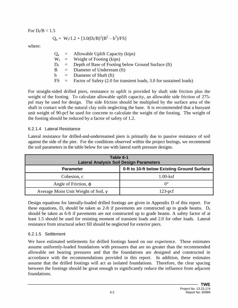
For Df/B < 1.5
Qa = Wf/1.2 + [3.0(Df/B)2(B
2 – b
2)/FS]
where:
Qa = Allowable Uplift Capacity (kips)
Wf = Weight of Footing (kips)
Df = Depth of Base of Footing below Ground Surface (ft)
B = Diameter of Underream (ft)
b = Diameter of Shaft (ft)
FS = Factor of Safety (2.0 for transient loads, 3.0 for sustained loads)
For straight-sided drilled piers, resistance to uplift is provided by shaft side friction plus the
weight of the footing. To calculate allowable uplift capacity, an allowable side friction of 275-
psf may be used for design. The side friction should be multiplied by the surface area of the
shaft in contact with the natural clay soils neglecting the base. It is recommended that a buoyant
unit weight of 90-pcf be used for concrete to calculate the weight of the footing. The weight of
the footing should be reduced by a factor of safety of 1.2.
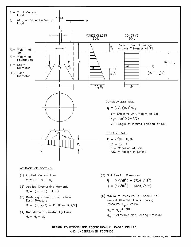
6.2.1.4 Lateral Resistance
Lateral resistance for drilled-and-underreamed piers is primarily due to passive resistance of soil
against the side of the pier. For the conditions observed within the project borings, we recommend
the soil parameters in the table below for use with lateral earth pressure designs.
Table 6-1 Lateral Analysis Soil Design Parameters
Parameter 0-ft to 10-ft below Existing Ground Surface
Cohesion, c 1.00-ksf
Angle of Friction, φ 0°
Average Moist Unit Weight of Soil, γ 123-pcf
Design equations for laterally-loaded drilled footings are given in Appendix D of this report. For
these equations, Ds should be taken as 2-ft if pavements are constructed up to grade beams. Ds
should be taken as 6-ft if pavements are not constructed up to grade beams. A safety factor of at
least 1.5 should be used for resisting moment of transient loads and 2.0 for other loads. Lateral
resistance from structural select fill should be neglected for exterior piers.
6.2.1.5 Settlement
We have estimated settlements for drilled footings based on our experience. These estimates
assume uniformly-loaded foundations with pressures that are no greater than the recommended
allowable net bearing pressures and that the foundations are designed and constructed in
accordance with the recommendations provided in this report. In addition, these estimates
assume that the drilled footings will act as isolated foundations. Therefore, the clear spacing
between the footings should be great enough to significantly reduce the influence from adjacent
foundations.
TWE Project No. 13.23.174 6-3 Report No. 60989
The recommended clear spacing between drilled footings should be a minimum of one (1)
underream diameter or straight-sided drilled pier diameter, respectively, for foundation design.
Settlement of properly-designed and installed drilled footings is estimated to be less than about
1-in. Differential settlement is expected to be on the order of one-half (½) the total settlement.
6.2.2 Building Floor Slab
As previously mentioned, the clay soils encountered within the project borings above 6-ft at the
project site possess high to very high shrink/swell potential. It is generally accepted that a
primary source of foundation distress is soil movements associated with shrink/swell behavior of
subgrade soils. It is therefore recommended that measures be incorporated into the design of
floor slabs for the proposed new building to reduce the shrink/swell potential of the foundation
soils.
6.2.2.1 Ground-Supported Floor Slabs
The floor slab of the proposed building may consist of a ground-supported floor slab provided
that remedial methods are used to reduce the potential for shrink/swell movement to tolerable
levels. The typical method for reducing shrink/swell potential includes the installation of a non-
expansive soil layer beneath the floor slab. This method has beneficial results but does not
totally eliminate the potential for shrink/swell movements.
In order to reduce the potential shrink/swell movements to tolerable limits of about 1-in or less, it
is recommended that a minimum of 2-ft of non-expansive select structural fill be provided
beneath the floor slab. We recommend that the 2-ft of non-expansive material consist of
properly-compacted sandy lean clay (CL) material having a liquid limit less than 40 and a
plasticity index between 10 and 20.
The minimum fill thickness may be provided by undercutting the existing material and replacing
it with select fill, raising the building pad with select fill or a combination of these alternatives.
Structural select fill should extend full depth at least 2-ft beyond the perimeter of the building
area.
It should be noted that these methods for reducing shrink/swell movements are designed for
normal seasonal changes in soil moisture content of the subgrade soils. Excessive shrink/swell
movements can be expected if increases in soil moisture content occur as a result of broken water
and sewer lines, improper drainage of surface water, landscaping planted near the foundation
slab and excessive irrigation.
After stripping the building area and prior to placement of fill, the exposed subgrade should be
inspected by the Geotechnical Engineer or his representative and proofrolled to identify any soft or
pumping soils. Soft or pumping soils should be removed to a level of firm soils and replaced with
fill material satisfying the requirements of this report.
TWE Project No. 13.23.174 6-4 Report No. 60989
Special care should be taken not to allow the exposed subgrade soils to become extremely wet or
extremely dry of the existing moisture content. Therefore, delays between excavation and fill
placement should be avoided. If construction occurs during rainy weather and the exposed
subgrade soils are allowed to become wet or saturated, removal or stabilization of excessively soft
and wet soils should be anticipated. The depth of undercutting or stabilization should be determined
in the field by the Geotechnical Engineer or his representative. Proofrolling and undercutting
should also be performed under the direction of the Geotechnical Engineer or his representative.
After proofrolling, the top 6-in of subgrade soils should be scarified and compacted to 95% of the
maximum dry density and within 3% of the optimum moisture content as determined by ASTM D
698 (Standard Proctor Compaction Effort).
It is recommended that a vapor barrier such as polyethylene sheeting be provided beneath soil
supported floor slabs. Adequate construction joints and reinforcement should be provided to
reduce the potential for cracking of the floor slab due to differential movement and volume
change in concrete.
TWE Project No. 13.23.174 7-1 Report No. 60989
7 CONSTRUCTION CONSIDERATIONS
7.1 Subgrade Preparation
Areas designated for new construction should be stripped of all surface vegetation, loose topsoil,
debris and fill material. The exposed soil subgrade should then be proofrolled with at least a 15-
ton pneumatic roller, loaded dump truck or equivalent to detect weak areas. Such weak areas
should be removed and replaced with properly-compacted select fill. Subsequent to proofrolling
and just prior to placement of select fill, the exposed subgrade should be compacted to at least
95% of the maximum dry density near optimum (to +3%) in accordance with ASTM D 698
procedures.
Proper site drainage should be maintained during construction so that ponding of surface runoff
does not occur and cause construction delays or inhibit site access. If the natural subgrade
becomes wet and soft, consideration can be given to either removal and replacement of the wet
material with structural fill or in-place stabilization with lime.
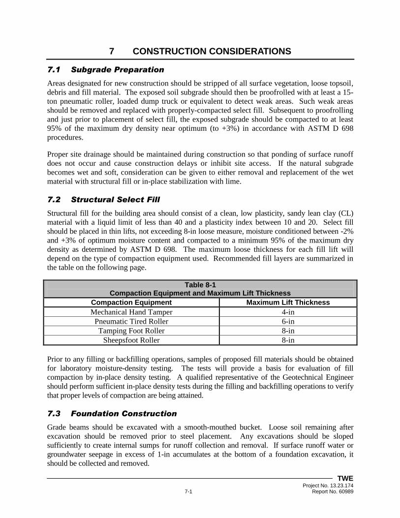
7.2 Structural Select Fill
Structural fill for the building area should consist of a clean, low plasticity, sandy lean clay (CL)
material with a liquid limit of less than 40 and a plasticity index between 10 and 20. Select fill
should be placed in thin lifts, not exceeding 8-in loose measure, moisture conditioned between -2%
and +3% of optimum moisture content and compacted to a minimum 95% of the maximum dry
density as determined by ASTM D 698. The maximum loose thickness for each fill lift will
depend on the type of compaction equipment used. Recommended fill layers are summarized in
the table on the following page.
Table 8-1 Compaction Equipment and Maximum Lift Thickness
Compaction Equipment Maximum Lift Thickness
Mechanical Hand Tamper 4-in
Pneumatic Tired Roller 6-in
Tamping Foot Roller 8-in
Sheepsfoot Roller 8-in
Prior to any filling or backfilling operations, samples of proposed fill materials should be obtained
for laboratory moisture-density testing. The tests will provide a basis for evaluation of fill
compaction by in-place density testing. A qualified representative of the Geotechnical Engineer
should perform sufficient in-place density tests during the filling and backfilling operations to verify
that proper levels of compaction are being attained.
7.3 Foundation Construction
Grade beams should be excavated with a smooth-mouthed bucket. Loose soil remaining after
excavation should be removed prior to steel placement. Any excavations should be sloped
sufficiently to create internal sumps for runoff collection and removal. If surface runoff water or
groundwater seepage in excess of 1-in accumulates at the bottom of a foundation excavation, it
should be collected and removed.
TWE Project No. 13.23.174 7-2 Report No. 60989
Excavations made in the building area for construction of grade beams and floor slabs should not
be allowed to remain open for extended periods. If excavations are to remain open, the use of a
concrete mud mat to reduce moisture changes or other damage to the natural subgrade soils
should be considered. If soft or loose soils are encountered at the design excavation level, they
should be undercut to firm or dense soils and the excavation backfilled with lean concrete.
The performance of the building foundation system will be highly dependent upon the quality of
construction. Thus, it is recommended that foundation construction be monitored by the
Geotechnical Engineer or his qualified representative to identify the proper bearing strata and
depths and to help evaluate foundation construction. TWE would be pleased to develop a plan
for foundation monitoring to be incorporated in the overall quality control program.
7.4 Drilled Footing Installation
The following items are important to the successful completion of drilled footing foundations.
All footing excavations should be observed by the Geotechnical Engineer or his
representative to determine when the proper bearing stratum is encountered and to record
other observations regarding pier construction.
Footing excavations should be checked for size and depth prior to the placement of
concrete. Precautions should be taken during the placement of the footing reinforcement
and concrete to prevent loose excavated material from falling into the excavation.
Drilled footings should be installed in accordance with the "Manual on Drilled Shafts:
Construction Procedures and Design Methods", [U.S. Department of Transportation-
Federal Highway Administration (Pub. No. FHWA-IF-99-025) and ADSC: The
International Association of Foundation Drilling Contractors (Pub. No. ADSC-TL-4),
August 1999] by Lymon, C. Reese and Michael W. O'Neill.
Due to the anticipated proximity of the water table to the recommended footing depth at
this site, we do not expect that seepage into drilled excavations will be significant during
construction. However, we recommend that groundwater levels be verified at the time of
construction. If groundwater levels are shallower than 10-ft at the time of construction,
TWE should be notified and recommendations provided herein reevaluated, if necessary.
Reinforcement steel cages placed in footing shafts should be designed to be stable during
the placement of concrete.
Prompt placement of concrete in excavations as they are completed, cleaned and inspected is
strongly recommended to limit deterioration of the bearing stratum. Under no circumstances should
a footing be drilled that cannot be filled with concrete before the end of the work day.
TWE Project No. 13.23.174 8-1 Report No. 60989
8 LIMITATIONS AND DESIGN REVIEW
8.1 Limitations
This report has been prepared for the exclusive use of Chica & Associates, Inc. and their project
team for specific application to the design and construction of the proposed new building at the
intersection of Shreveport Avenue and 4th
Street in Port Arthur, Texas. Our report has been
prepared in accordance with the generally accepted geotechnical engineering practice common to
the local area. No other warranty, express or implied, is made.
The analyses and recommendations contained in this report are based on the data obtained from
the referenced soil borings performed within the project site. The soil borings indicate
subsurface conditions only at the specific locations, times and depths penetrated. The soil
borings do not necessarily reflect strata variations that may exist at other locations within the
project site. The validity of our recommendations is based in part on assumptions about the
stratigraphy made by the Geotechnical Engineer. Such assumptions may be confirmed only
during the construction phase of the project. Our recommendations presented in this report must
be reassessed if subsurface conditions during construction are different from those described in
this report.
If any changes in the nature, design or location of the project are planned, the conclusions and
recommendations contained in this report should not be considered valid unless the changes are
reviewed and the conclusions modified or verified in writing by TWE. TWE is not responsible
for any claims, damages or liability associated with interpretation or reuse of the subsurface data
or engineering analyses without the expressed written authorization of TWE.
8.2 Design Review
Review of the design and construction drawings as well as the specifications should be
performed by TWE before release. The review is aimed at determining if the geotechnical
design and construction recommendations contained in this report have been properly
interpreted. Design review is not within the authorized scope of work for this study.
8.3 Construction Monitoring
Construction surveillance is recommended and has been assumed in preparing our
recommendations. These field services are required to check for changes in conditions that may
result in modifications to our recommendations. The quality of the construction practices will
affect performance of the project structures and should be monitored. TWE would be pleased to
provide construction monitoring, testing and inspection services for the project.
8.4 Closing Remarks
We appreciate the opportunity to be of service during this phase of the project and we look
forward to continuing our services during the construction phase and on future projects.
TWE Project No. 13.23.174 Report No. 60989
APPENDIX A
PROJECT INFORMATION
CHICA & ASSOCIATES, INC.


TWE Project No. 13.23.174 Report No. 60989
APPENDIX B
SOIL BORING LOCATION PLAN
DRAWING NO. 13.23.174-1

DRAWN BY:
CHECKED BY:
APPROVED BY:
SCALE:
DWG. NO.
DATE:
M.M.
T.G.H.
P.J.K.
SOIL BORING LOCATION PLAN
PROPOSED NEW BUILDING
PORT ARTHUR, TEXAS
13.23.174-1
N.T.S.
JULY 31, 2013
VICINITY MAP
PROJECT
LOCATION
COPYRIGHT © 2013 GOOGLE EARTH. ALL RIGHTS RESERVED.
COPYRIGHT © 2013 GOOGLE MAPS. ALL RIGHTS RESERVED.
BORING LONGITUDELATITUDE
B-1 29° 52' 23.70" N 93° 55' 52.00" W
DEPTH
30'
SOIL BORING LOCATION
LEGEND
SOIL BORING COORDINATES
B-1
F
O
U
R
T
H
S
T
R
E
E
T
D.P.S.
BUILDING
DD7
PUMP STATION
TWE Project No. 13.23.174 Report No. 60989
APPENDIX C
PROJECT BORING LOG B-1 AND A
KEY TO SYMBOLS AND TERMS USED ON BORING LOGS

0
5
10
15
20
25
30
35
Stiff gray FAT CLAY (CH)
-with shell and organics from 0' to 2'
-becomes gray and reddish brown at 2'
-with ferrous nodules from 2' to 4'
-becomes firm at 4'
-with ferrous nodules from 6' to 10'
-with calcareous nodules from 8' to 15'
-becomes stiff at 10'
-becomes reddish brown at 13'
-with sand pockets from 13' to 15'
Stiff brown and reddish brown LEAN CLAY with
SAND (CL)
Stiff brown and gray FAT CLAY (CH), with sand
seams
-becomes firm at 28'
-with silt layers from 28' to 30'
Bottom @ 30'
(P)2.00
(P)1.25
(P)1.25
(P)1.00
(P)1.25
(P)1.75
(P)2.50
(P)2.00
(P)1.25
7/6"
8/6"
9/6"
21
26
29
30
31
28
106
100
93
90
51
71
73
28
35
57
56
11
1.28
0.90
0.74
11
15
13
3
6
8
91
81
TOLUNAY-WONG ENGINEERS, INC.
LOG OF BORING B-1PROJECT: Proposed New Building
Port Arthur, Texas
CLIENT: Chica & Associates, Inc.
Beaumont, Texas
COMPLETION DEPTH: 30 ft NOTES:
Free water was encountered at a depth of 18-ft during dry-auger drilling and rose to
a depth of 9-ft after fifteen (15) minutes. The open borehole was backfilled with
cement-bentonite grout.
DATE BORING STARTED: 07/19/13
DATE BORING COMPLETED: 07/19/13
LOGGER: T. McClain
PROJECT NO.: 13.23.174 Page 1 of 1
EL
EV
AT
IO
N (F
T)
---------------------------
DE
PT
H (F
T)
SA
MP
LE
T
YP
E
SY
MB
OL
MATERIAL DESCRIPTION
COORDINATES:
SURFACE ELEVATION:
DRILLING METHOD:
Dry Augered: to
Wash Bored: to
(P
) P
OC
KE
T P
EN
(tsf)
(T
) T
OR
VA
NE
(tsf)
ST
D. P
EN
ET
RA
TIO
N
TE
ST
B
LO
WC
OU
NT
MO
IS
TU
RE
CO
NT
EN
T (%
)
DR
Y U
NIT
W
EIG
HT
(p
cf)
LIQ
UID
L
IM
IT
(%
)
PL
AS
TIC
IT
Y
IN
DE
X (%
)
CO
MP
RE
SS
IV
E
ST
RE
NG
TH
(tsf)
FA
ILU
RE
S
TR
AIN
(%
)
CO
NF
IN
IN
G
PR
ES
SU
RE
(p
si)
PA
SS
IN
G #
20
0
SIE
VE
(%
)
OT
HE
R T
ES
TS
PE
RF
OR
ME
D
--
0' 20'
20' 30'
29° 52' 23.70"
93° 55' 52.00"
N
W

TWE Project No. 13.23.174 Report No. 60989
APPENDIX D
DESIGN EQUATIONS FOR ECCENTRICALLY-LOADED DRILLED-AND-
UNDERREAMED FOOTINGS