geotechnical engineering investigation · 2019. 10. 10. · geotechnical engineering study ....
TRANSCRIPT

G E O T E C H N I C A L E N G I N E E R I N G S T U D Y
Proposed 5 Level Apartments 1750 West 1700 South Salt Lake City, Utah CMT PROJECT NO. 13140 FOR: Stone River Construction 10605 North 6250 West Highland, Utah 84003 August 19, 2019
ENG
INEERIN
G •G
EOTECH
NICAL •EN
VIRON
MEN
TAL (ESA I & II) •
MATERIA
LS TESTING
•SPECIAL IN
SPECTION
S • O
RGAN
IC CHEM
ISTRY • PAVEMEN
T D
ESIGN
•GEO
LOG
Y

ENGINEERING • GEOTECHNICAL • ENVIRONMENTAL (ESA I & II) • MATERIALS TESTING • SPECIAL INSPECTIONS
ORGANIC CHEMISTRY • PAVEMENT DESIGN • GEOLOGY www.cmtlaboratories.com
8/19/19
August 19, 2019 Mr. Ryan Hales Stone River Construction 10605 North 6250 West Highland, Utah 84003 Subject: Geotechnical Engineering Study Proposed 5 Level Apartment Building 1750 West 1700 South Salt Lake City, Utah CMT Project Number: 13140 Mr. Hales: Submitted herewith is the report of our geotechnical engineering study for the subject site. This report contains the results of our findings and an engineering interpretation of the results with respect to the available project characteristics. It also contains recommendations to aid in the design and construction of the earth related phases of this project. On August 1, 2019, a CMT Engineering Laboratories (CMT) geologist was on-site and supervised the drilling of 5 bore holes extending to depths of about 6.5 to 71.5 feet below the existing ground surface. Soil samples were obtained during the field operations and subsequently transported to our laboratory for further testing and observation. Conventional spread and/or continuous footings may be utilized to support the proposed structure(s), provided the recommendations in this report are followed. A detailed discussion of design and construction criteria is presented in this report. We appreciate the opportunity to work with you at this stage of the project. CMT offers a full range of Geotechnical Engineering, Geological, Material Testing, Special Inspection services, and Phase I and II Environmental Site Assessments. With 9 offices throughout Utah, Idaho and Arizona, our staff is capable of efficiently serving your project needs. If we can be of further assistance or if you have any questions regarding this project, please do not hesitate to contact us at (801) 492-4132. Sincerely, CMT Engineering Laboratories Reviewed by: Jeffrey J. Egbert, P.E., LEED A.P., M. ASCE William G. Turner, P.E., M. ASCE Senior Geotechnical Engineer Senior Geotechnical Engineer

TABLE OF CONTENTS 1.0 INTRODUCTION ............................................................................................................................................................ 1
1.1 General ...................................................................................................................................................................................1 1.2 Objectives, Scope and Authorization ......................................................................................................................................1 1.3 Description of Proposed Construction ....................................................................................................................................2 1.4 Executive Summary ................................................................................................................................................................2
2.0 FIELD EXPLORATION ..................................................................................................................................................... 3 3.0 LABORATORY TESTING ................................................................................................................................................. 3 4.0 GEOLOGIC & SEISMIC CONDITIONS ............................................................................................................................... 4
4.1 Geologic Setting ......................................................................................................................................................................4 4.2 Faulting ...................................................................................................................................................................................6 4.3 Seismicity ................................................................................................................................................................................6
4.3.1 Site Class ..........................................................................................................................................................................6 4.3.2 Ground Motions ...............................................................................................................................................................7 4.3.3 Liquefaction .....................................................................................................................................................................8
4.4 Other Geologic Hazards ..........................................................................................................................................................8 5.0 SITE CONDITIONS ......................................................................................................................................................... 8
5.1 Surface Conditions ..................................................................................................................................................................8 5.2 Subsurface Soils ......................................................................................................................................................................8 5.3 Groundwater ..........................................................................................................................................................................9 5.4 Site Subsurface Variations ......................................................................................................................................................9
6.0 SITE PREPARATION AND GRADING ............................................................................................................................... 9 6.1 General ...................................................................................................................................................................................9 6.2 Temporary Excavations ........................................................................................................................................................ 10 6.3 Fill Material .......................................................................................................................................................................... 11 6.4 Fill Placement and Compaction ........................................................................................................................................... 11 6.5 Utility Trenches .................................................................................................................................................................... 12 6.6 Stabilization ......................................................................................................................................................................... 12
7.0 FOUNDATION RECOMMENDATIONS ........................................................................................................................... 13 7.1 Foundation Recommendations ........................................................................................................................................... 13 7.2 Installation ........................................................................................................................................................................... 14 7.3 Estimated Settlement .......................................................................................................................................................... 14 7.4 Lateral Resistance ................................................................................................................................................................ 14
8.0 LATERAL EARTH PRESSURES ....................................................................................................................................... 15 9.0 FLOOR SLABS ............................................................................................................................................................. 15 10.0 DRAINAGE RECOMMENDATIONS .............................................................................................................................. 16 11.0 PAVEMENTS ............................................................................................................................................................. 16 12.0 QUALITY CONTROL ................................................................................................................................................... 17
12.1 Field Observations ............................................................................................................................................................. 17 12.2 Fill Compaction .................................................................................................................................................................. 17 12.3 Excavations ........................................................................................................................................................................ 17 12.4 Vibration Monitoring ......................................................................................................................................................... 17
13.0 LIMITATIONS ............................................................................................................................................................ 18
APPENDIX Figure 1: Exploration Locations Figures 2 -6: Bore Hole Logs Figure 7: Key to Symbols

Geotechnical Engineering Study Page 1 Proposed 5 Level Apartment Building, Salt Lake City, Utah CMT Project No. 13140
1.0 INTRODUCTION
1.1 General CMT Engineering Laboratories (CMT) was retained to conduct a geotechnical subsurface study for a proposed 5 level apartment building or buildings. The site of the proposed construction is located at 1750 West 1700 South in Salt Lake City, Utah, as shown in the Vicinity Map below.
VICINITY MAP
1.2 Objectives, Scope and Authorization The objectives and scope of our study were planned in discussions between Mr. Ryan Hales of Stone River Construction, and Mr. Jeff Egbert of CMT Engineering Laboratories (CMT). In general, the objectives of this study were to define and evaluate the subsurface soil and groundwater conditions at the site, and provide appropriate foundation, earthwork, pavement and seismic recommendations to be utilized in the design and construction of the proposed development. In accomplishing these objectives, our scope of work has included performing field exploration, which consisted of the drilling/logging/sampling of 5 bore holes, performing laboratory testing on representative samples of the subsurface soils collected in the bore holes, and conducting an office program, which consisted of correlating
SITE
N

Geotechnical Engineering Study Page 2 Proposed 5 Level Apartment Building, Salt Lake City, Utah CMT Project No. 13140
available data, performing engineering analyses, and preparing this summary report. This scope of work was authorized by returning a signed copy of our proposal dated July 16, 2019 and executed on July 19, 2019.
1.3 Description of Proposed Construction We understand that the proposed construction consists of an apartment building or buildings with up to 5 levels above grade and a possible single level of parking below grade. We anticipate the structure or structures will be of wood or light steel frame construction, supported on reinforced concrete foundation walls and footings. We project that wall loads will not exceed 10,000 pounds per linear foot and column loads will not exceed 200,000 pounds. Floor slab loads are anticipated to be relatively light, with an average uniform loading not exceeding 150 pounds per square foot. If the loading conditions are different than we have projected, please notify us so that any appropriate modifications to our conclusions and recommendations contained herein can be made. Parking/drive paved areas will also be constructed, which we anticipate will utilize asphalt pavement. Traffic is projected to consist of mostly automobiles and light trucks, a few daily medium-weight delivery trucks, a weekly garbage truck, and an occasional fire truck. Site development will require some earthwork in the form of minor cutting and filling. A site grading plan was not available at the time of this report, but we project that maximum cuts and fills may be on the order of 3 to 4 feet. If deeper cuts or fills are planned, CMT should be notified to provide additional recommendations, if needed.
1.4 Executive Summary The most significant geotechnical aspects regarding site development include the following: 1. Approximately 1.5 to 5.5 feet of non-engineered fill blankets the site; foundations and floor slabs should
not be placed on non-engineered fill. 2. Subsurface natural soils predominately consist of CLAY (CL, CL-ML) and SILT (ML), with a few deeper
layers of SAND (SM). The clay soils have moderate to moderately high compressibility characteristics. 3. Groundwater was encountered at depths of about 10 to 12 feet below the existing site grade, and was
later measured in one bore hole (B-3) at a depth of 8 feet 4 inches. Wet, possibly soft soils may be encountered in footing excavations for a below grade parking level.
4. Foundations and floor slabs may be constructed on suitable undisturbed natural soils or on structural/engineered fill which extends to natural soils. More heavily loaded footings will require structural/engineered fill to minimize potential settlements.
CMT must assess that topsoil, non-engineered fills, debris, disturbed or other unsuitable soils have been removed and that suitable soils have been encountered prior to placing site grading fills, footings, or slabs.

Geotechnical Engineering Study Page 3 Proposed 5 Level Apartment Building, Salt Lake City, Utah CMT Project No. 13140
In the following sections, detailed discussions pertaining to the site and subsurface descriptions, geologic/seismic setting, earthwork, foundations, lateral resistance, lateral pressure, floor slabs, and pavements are provided.
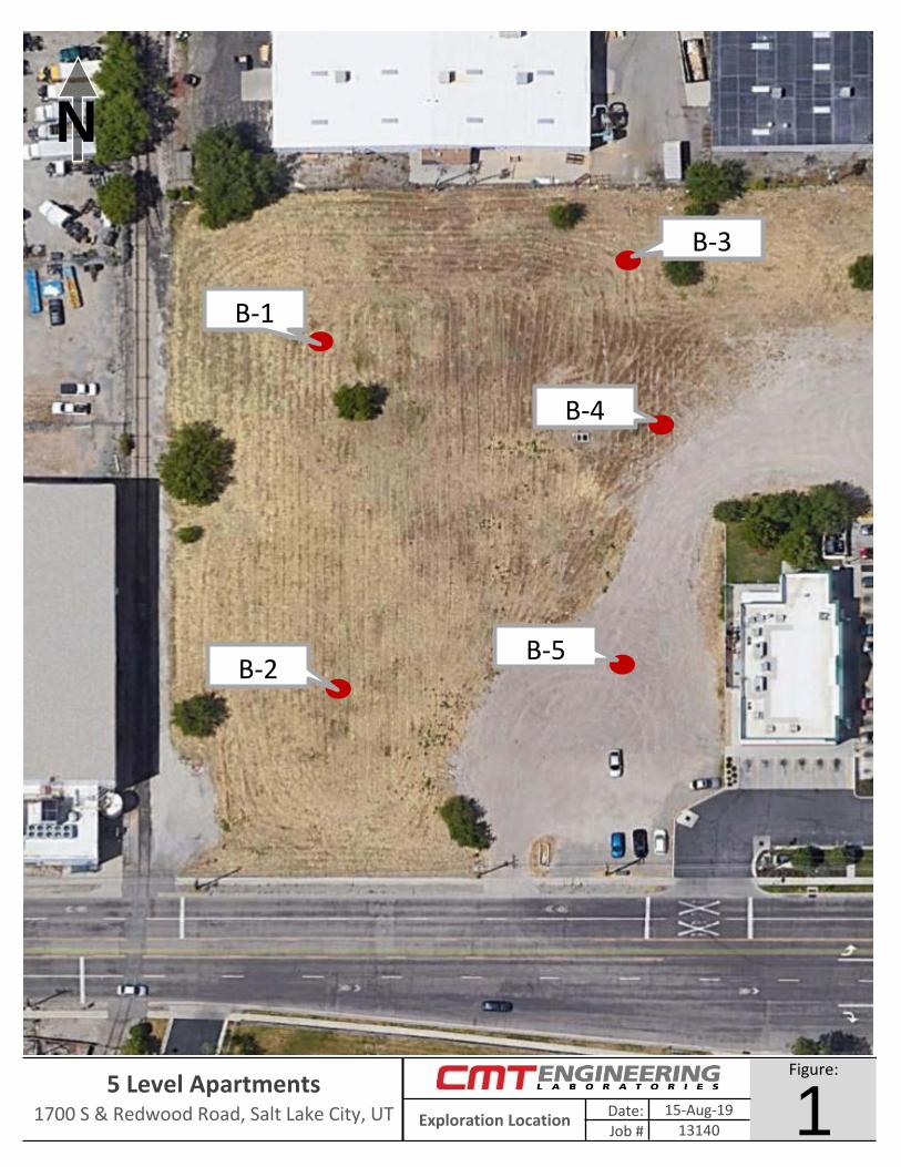
2.0 FIELD EXPLORATION In order to define and evaluate the subsurface soil and groundwater conditions 5 bore holes were drilled at the site to depths of approximately 6.5 to 71.5 feet below the existing ground surface. Locations of the bore holes are presented on Figure 1. Samples of the subsurface soils encountered in the bore holes were collected at varying depths through the hollow stem drill augers. Relatively undisturbed samples were obtained by hydraulically pushing a 3-inch diameter (Shelby) tube into the undisturbed soils below the drill augers. Disturbed samples were collected utilizing a standard split spoon sampler. This standard split spoon sampler was driven 18 inches into the soils below the drill augers using a 140 pound hammer free-falling a distance of 30 inches. The number of hammer blows needed for each 6 inch interval was recorded. The sum of the hammer blows for the final 12 inches of penetration is known as a standard penetration test and this ‘blow count’ was recorded on the bore hole logs. Where more than 50 blows occurred before the 6 inch interval was achieved, the sampling was terminated and the number of blows and inches penetrated by the sampler were recorded. The blow count provides a reasonable approximation of the relative density of granular soils, but only a limited indication of the relative consistency of fine grained soils because the consistency of these soils is significantly influenced by the moisture content. The subsurface soils encountered in the bore holes were logged and described in general accordance with ASTM1 D-2488. Soil samples were collected as described above, and were classified in the field based upon visual and textural examination. These field classifications were supplemented by subsequent examination and testing of select samples in our laboratory. Logs of the bore holes, including a description of the soil strata encountered, is presented on each individual Bore Hole Log, Figures 2 through 6, included in the Appendix. Sampling information and other pertinent data and observations are also included on the logs. In addition, a Key to Symbols defining the terms and symbols used on the logs is provided as Figure 7 in the Appendix. Following completion of drilling operations, a 1.25-inch diameter slotted PVC pipe was installed in bore hole B-3 to allow subsequent water level measurements.
3.0 LABORATORY TESTING
Selected samples of the subsurface soils were subjected to various laboratory tests to assess pertinent engineering properties, as follows: 1. Moisture Content, ASTM D-2216, Percent moisture representative of field conditions 2. Dry Density, ASTM D-2937, Dry unit weight representing field conditions 1American Society for Testing and Materials

Geotechnical Engineering Study Page 4 Proposed 5 Level Apartment Building, Salt Lake City, Utah CMT Project No. 13140
3. Atterberg Limits, ASTM D-4318, Plasticity and workability 4. Gradation Analysis, ASTM D-1140/C-117, Grain Size Analysis 5. One Dimension Consolidation, ASTM D-2435, Consolidation properties 6. Vane Shear Test, ASTM D-4648, Shear strength parameters Based upon data obtained from the consolidation testing, the clay soils at this site are slightly to moderately over-consolidated and have moderate to moderately high compressibility under additional loading. One of the samples (B-2 at 5 feet) showed about 1% moisture related settlement (collapse) when the sample was at a load of 1,000 psf and water was added (see the Lab Summary Table below). Detailed results of the tests are maintained within our files and can be transmitted to you, if so desired. Laboratory test results are presented on the bore hole logs (Figures 2 through 6) and in the following Lab Summary Table:
LAB SUMMARY TABLE Bore Depth Soil Sample Moisture Dry Denstiy Collapse (-) or Vane Shear
Hole (feet) Class Type Content (%) (pcf) Grav Sand Fines LL PL PI Expansion (+) (psf)
B-1 5 CL Shelby 11.4 25 16 910 ML Shelby 23.9 94.1 20 18 225 CL-ML Shelby 35.8 88.2 24 19 5 123335 SM SPT 16.4 2360 SM SPT 24.7 12
B-2 5 CL Shelby 27.4 96.1 27 19 8 -1.0%10 ML Shelby 27.5 NP20 ML Shelby 36.8 89.6
B-3 15 ML Shelby 29.8 21 20 125 CL SPT 32.0 89.3 26 20 6 1909
B-4 5 CL-ML SPT 22.4 26 20 6
Gradation Atterberg Limits
4.0 GEOLOGIC & SEISMIC CONDITIONS
4.1 Geologic Setting The subject site is located in the north-central portion of the Salt Lake Valley in north-central Utah at an elevation of approximately 4,240 feet above sea level. The Salt Lake Valley is a deep, sediment-filled basin that is part of the Basin and Range Physiographic Province. The valley is bounded by the Wasatch Mountain Range on the east and the Oquirrh Mountain Range on the west. The valley was formed by extensional tectonic processes during the Tertiary and Quaternary geologic time periods. The subject site and surrounding areas are located within the Intermountain Seismic Belt, a zone of ongoing tectonism and seismic activity extending from southwestern Montana to southwestern Utah. The active (evidence of movement in the last 10,000 years) Wasatch Fault Zone is part of the Intermountain Seismic Belt and extends from southeastern Idaho to central Utah along the western base of the Wasatch Mountain Range.
Geotechnical Engineering Study Page 5 Proposed 5 Level Apartment Building, Salt Lake City, Utah CMT Project No. 13140
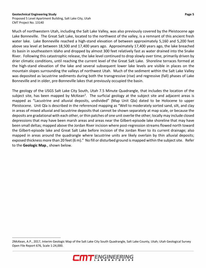
Much of northwestern Utah, including the Salt Lake Valley, was also previously covered by the Pleistocene age Lake Bonneville. The Great Salt Lake, located to the northwest of the valley, is a remnant of this ancient fresh water lake. Lake Bonneville reached a high-stand elevation of between approximately 5,160 and 5,200 feet above sea level at between 18,500 and 17,400 years ago. Approximately 17,400 years ago, the lake breached its basin in southeastern Idaho and dropped by almost 300 feet relatively fast as water drained into the Snake River. Following this catastrophic release, the lake level continued to drop slowly over time, primarily driven by drier climatic conditions, until reaching the current level of the Great Salt Lake. Shoreline terraces formed at the high-stand elevation of the lake and several subsequent lower lake levels are visible in places on the mountain slopes surrounding the valleys of northwest Utah. Much of the sediment within the Salt Lake Valley was deposited as lacustrine sediments during both the transgressive (rise) and regressive (fall) phases of Lake Bonneville and in older, pre-Bonneville lakes that previously occupied the basin. The geology of the USGS Salt Lake City South, Utah 7.5 Minute Quadrangle, that includes the location of the subject site, has been mapped by McKean2. The surficial geology at the subject site and adjacent areas is mapped as “Lacustrine and alluvial deposits, undivided” (Map Unit Qla) dated to be Holocene to upper Pleistocene. Unit Qla is described in the referenced mapping as “Well to moderately sorted sand, silt, and clay in areas of mixed alluvial and lacustrine deposits that cannot be shown separately at map scale, or because the deposits are gradational with each other, or thin patches of one unit overlie the other; locally may include closed depressions that may have been marsh areas and areas near the Gilbert-episode lake shoreline that may have been small deltas; mapped above the Jordan River incision where post-regression streams flowed north toward the Gilbert-episode lake and Great Salt Lake before incision of the Jordan River to its current drainage; also mapped in areas around the quadrangle where lacustrine units are likely overlain by thin alluvial deposits; exposed thickness more than 20 feet (6 m).” No fill or disturbed ground is mapped within the subject site. Refer to the Geologic Map., shown below.
2McKean, A.P., 2017, Interim Geologic Map of the Salt Lake City South Quadrangle, Salt Lake County, Utah; Utah Geological Survey Open File Report 676, Scale 1:24,000.

Geotechnical Engineering Study Page 6 Proposed 5 Level Apartment Building, Salt Lake City, Utah CMT Project No. 13140
GEOLOGIC MAP
4.2 Faulting No active fault rupture traces are mapped crossing, adjacent to, or projecting toward the subject site. The nearest mapped active fault is the Taylorsville Fault of the West Valley Fault Zone which is located approximately 0.56 miles to the west.
4.3 Seismicity 4.3.1 Site Class Utah has adopted the International Building Code (IBC) 2018, which determines the seismic hazard for a site based upon 2014 mapping of bedrock accelerations prepared by the United States Geologic Survey (USGS) and the soil site class. The USGS values are presented on maps incorporated into the IBC code and are also available based on latitude and longitude coordinates (grid points). For site class definitions, IBC 2018 Section 1613.2.2 refers to Chapter 20, Site Classification Procedure for Seismic Design, of ASCE3 7-16. Given the subsurface soils encountered at the site, including our projection of soils below the maximum depth explored of 71.5 feet to a depth of 100 feet, it is our opinion the site best fits Site Class D – Stiff Soil Profile (with data), which we recommend for seismic structural design.
3American Society of Civil Engineers
SITE

Geotechnical Engineering Study Page 7 Proposed 5 Level Apartment Building, Salt Lake City, Utah CMT Project No. 13140
4.3.2 Ground Motions The 2014 USGS mapping utilized by the IBC provides values of peak ground, short period and long period accelerations for the Site Class B/C boundary and the Maximum Considered Earthquake (MCE). This Site Class B/C boundary represents average bedrock values for the Western United States and must be corrected for local soil conditions. The following table summarizes the peak ground, short period and long period accelerations for the MCE event, and incorporates appropriate soil correction factors and any possible exceptions for a Site Class D soil profile at site grid coordinates of 40.7337 degrees north latitude and -111.9405 degrees west longitude (also see response spectrum below):
Peak Ground Acceleration PGA = 0.692 Fpga = 1.100 PGAM = 0.761 1.000 PGAM = 0.761SS = 1.532 Fa = 1.000 SMS = 1.532 0.667 SDS = 1.021
Fa = (N/A) SMS = (N/A) 0.667 SDS = (N/A)S1 = 0.540 Fv = N/A SM1 = N/A 0.667 SD1 = N/A
Fv = (1.760) SM1 = (0.950) 0.667 SD1 = (0.634)NOTES: * Site Class D With Data1. TL = 8 seconds2. Site Class: D3. Have data to verify? yes
4. ASCE 7-16 requires Site Specific Ground Motion Hazard Analysis (S1 ≥ 0.2), OR Can Use Exception 2
SPECTRAL ACCELERATION VALUE, T
SITE CLASS B/C BOUNDARY [mapped values] (g)
SITE COEFFICIENT
SITE CLASS D* [adjusted for site class effects] (g)
MULTI-PLIER
DESIGN VALUES (g)
0.2 Seconds (Long Period Acceleration)
1.0 Second (Long Period Acceleration)
(exceptions, if any)
(exceptions, if any)
0
0.2
0.4
0.6
0.8
1
1.2
0 0.5 1 1.5 2 2.5 3 3.5 4
Spec
tral
Resp
onse
Acc
eler
atio
n, S
a (g
)
Period, T (seconds)
Baseline Sa (not for design)
Sa (Adjusted for Any Exceptions)

Geotechnical Engineering Study Page 8 Proposed 5 Level Apartment Building, Salt Lake City, Utah CMT Project No. 13140
4.3.3 Liquefaction The site is located within an area designated by the Utah Geologic Survey4 as having “High” liquefaction potential. Liquefaction is defined as the condition when saturated, loose, sandy soils lose their support capabilities because of excessive pore water pressure which develops during a seismic event. Clayey soils, even if saturated, will generally not liquefy during a major seismic event. Subsurface soils encountered predominately consisted of silt/clay, typically not liquefiable, with some deeper layers of sand that appear to be in a dense state. Based upon these conditions we estimate a low liquefaction potential for the soils we encountered.
4.4 Other Geologic Hazards No landslide deposits or features, including lateral spread deposits, are mapped on or adjacent to the site. The site is not located within a currently known or mapped potential debris flow, stream flooding, or rock fall hazard area.
5.0 SITE CONDITIONS
5.1 Surface Conditions At the time the bore holes were drilled the site consisted of a vacant lot with weeds, grasses, and a few trees. Fill soils were observed on the surface. Overall, the site was relatively flat. Based upon aerial photos dating back to 1997 that are readily available on the internet, it appears that the site was part of a larger parcel previously occupied by what appears to be an industrial building. Most of the previous industrial building appears to have been removed by mid-2005 and no structures are present by late 2006. The site appears to have remained relatively unchanged since mid-2005. The site is bordered on the north and west by commercial/industrial buildings, on the east by a convenience store and a fast food restaurant, and on the south by 1700 South Street (see Vicinity Map in Section 1.1 above).
5.2 Subsurface Soils At the locations of the bore holes we encountered fill soils considered non-engineered (not placed in a controlled manner or tested for compaction) on the surface, extending to depths of between 1.5 and 5.5 feet. Natural soils were observed beneath the non-engineered fill soils, consisting mostly of CLAY (CL), SILTY CLAY (CL-ML), and SILT (ML) layers, with a few deeper layers of Silty SAND (SM), extending to the bottom of the bore holes.
4 Utah Geological Survey, "Liquefaction-Potential Map for a Part of Salt Lake County, Utah," Utah Geological Survey Public Information Series 25, August 1994. https://ugspub.nr.utah.gov/publications/public_information/pi-25.pdf

Geotechnical Engineering Study Page 9 Proposed 5 Level Apartment Building, Salt Lake City, Utah CMT Project No. 13140
The silt/clay soils were slightly moist to wet, light brown to dark gray in color, and SPT blow counts indicate consistencies ranging from soft to stiff. They also exhibited slight to moderate over consolidation, with moderate to moderately high compressibility characteristics. The sand layers were wet, blue-gray to gray in color, and with SPT blow counts indicating dense to very dense relative density. For a more descriptive interpretation of subsurface conditions, please refer to the bore hole logs, Figures 2 through 6, which graphically represent the subsurface conditions encountered. The lines designating the interface between soil types on the logs generally represent approximate boundaries; in situ, the transition between soil types may be gradual. 5.3 Groundwater Groundwater was encountered in the bore holes at depths of about 10 to 12 feet below existing grade at the time of our field exploration. On August 19, 2019, CMT personnel returned to the site and measured the groundwater level at a depth of about 8 feet 4 inches below the surface within the slotted PVC pipe installed in bore hole B-3. Groundwater levels can fluctuate as much as 1.5 to 2 feet seasonally. Numerous other factors such as heavy precipitation, irrigation of neighboring land, and other unforeseen factors, may also influence ground water elevations at the site. The detailed evaluation of these and other factors, which may be responsible for ground water fluctuations, is beyond the scope of this study.
5.4 Site Subsurface Variations Based on the results of the subsurface explorations and our experience, variations in the continuity and nature of subsurface conditions should be anticipated. Due to the heterogeneous characteristics of natural soils, care should be taken in interpolating or extrapolating subsurface conditions between or beyond the exploratory locations.
6.0 SITE PREPARATION AND GRADING
6.1 General All deleterious materials should be stripped from the site prior to commencement of construction activities. This includes vegetation, topsoil, loose and disturbed soils, etc. Based upon the conditions observed at the time of our subsurface exploration, approximately 1.5 to 5.5 feet of non-engineered fill is present on the surface of the site, along with vegetation and topsoil. All non-engineered fill shall be removed from beneath structures. Outside of building footprints, the non-engineered fill may remain in place if properly prepared and if the owner accepts that some settlement of pavement and exterior flatwork could occur; otherwise, the non-engineered

Geotechnical Engineering Study Page 10 Proposed 5 Level Apartment Building, Salt Lake City, Utah CMT Project No. 13140
fill should be removed in those areas as well. Proper preparation of non-engineered fill and disturbed soils shall consist of removing the upper 12 inches of the fill below the pavement and exterior concrete flatwork subgrade levels, scarifying the exposed surface of the non-engineered fill to a minimum depth of 9 inches, moisture conditioning, and re-compacting the scarified soils in place to 95% of the maximum density. The removed 12 inches of non-engineered fill may then be replaced in similarly compacted lifts. Any debris, organics, or other unsuitable materials encountered in this process should be removed prior to re-compacting. We also recommend that the subgrade then be proofrolled by passing moderate-weight rubber tire-mounted construction equipment over the surface at least twice. If excessively soft or loose soils are encountered, they must be removed (up to a maximum depth of 2 feet) and replaced with structural fill. The site should be examined by a CMT geotechnical engineer to assess that suitable natural soils have been exposed and any deleterious materials, loose and/or disturbed soils have been removed, prior to placing site grading fills, footings, slabs, and/or in pavement areas, that the non-engineered fill surface has been properly prepared. Fill placed over large areas to raise overall site grades can induce settlements in the underlying natural soils. If more than 3 feet of site grading fill is anticipated over the natural ground surface, we should be notified to assess potential settlements and provide additional recommendations as needed. These recommendations may include placement of the site grading fill far in advance to allow potential settlements to occur prior to construction.
6.2 Temporary Excavations Excavations deeper than 10 feet are not anticipated at the site. Groundwater was encountered within the depths explored, about 10 to 12 feet at the time of our field explorations, and later measured in B-3 at about 8.3 feet below the surface. Wet and/or soft soils could be encountered in excavations extending below about 8 feet. Dewatering of such excavations may be required. The natural soils encountered at this site predominantly consisted of silt/clay. In clayey (cohesive) soils, temporary construction excavations not exceeding 4 feet in depth may be constructed with near-vertical side slopes. Temporary excavations up to 10 feet deep, above or below groundwater, may be constructed with side slopes no steeper than one-half horizontal to one vertical (0.5H:1V). For sandy/gravelly (cohesionless) soils, temporary construction excavations not exceeding 4 feet in depth should be no steeper than one-half horizontal to one vertical (0.5H:1V). For excavations up to 8 feet and above groundwater, side slopes should be no steeper than one horizontal to one vertical (1H:1V). Excavations encountering saturated cohesionless soils will be very difficult to maintain, and will require very flat side slopes and/or shoring, bracing and dewatering. To reduce disturbance of the natural soils during excavation, we recommend that smooth edge buckets/blades be utilized.

Geotechnical Engineering Study Page 11 Proposed 5 Level Apartment Building, Salt Lake City, Utah CMT Project No. 13140
All excavations must be inspected periodically by qualified personnel. If any signs of instability or excessive sloughing are noted, immediate remedial action must be initiated. All excavations should be made following OSHA safety guidelines.
6.3 Fill Material Following are our recommendations for the various fill types we anticipate will be used at this site:
FILL MATERIAL TYPE DESCRIPTION | RECOMMENDED SPECIFICATION
Structural Fill Placed below structures, flatwork and pavement. Well-graded sand/gravel mixture, with maximum particle size of 4 inches, a minimum 70% passing 3/4-inch sieve, a maximum 20% passing the No. 200 sieve, and a maximum Plasticity Index of 10.
Site Grading Fill Placed over larger areas to raise the site grade. Sandy to gravelly soil, with a maximum particle size of 6 inches, a minimum 70% passing 3/4-inch sieve, and a maximum 50% passing No. 200 sieve.
Non-Structural Fill Placed below non-structural areas, such as landscaping. On-site soils or imported soils, with a maximum particle size of 8 inches, including silt/clay soils not containing excessive amounts of degradable/organic material (see discussion below).
Stabilization Fill Placed to stabilize soft areas prior to placing structural fill and/or site grading fill. Coarse angular gravels and cobbles 1 inch to 8 inches in size. May also use 1.5- to 2.0-inch gravel placed on stabilization fabric, such as Mirafi RS280i, or equivalent (see Section 6.6).
On-site silt/clay soils may be used as site grading fill and non-structural fill, but are also moisture-sensitive. Note that such moisture-sensitive soils are inherently more difficult to work with in proper moisture conditioning (they are very sensitive to changes in moisture content), requiring very close moisture control during placement and compaction. This will be very difficult, if not impossible, during wet and cold periods of the year. We also recommend the site grading fill thickness using on-site silt/clay soils not exceed 3 feet below structures, to minimize potential settlements. All fill material should be approved by a CMT geotechnical engineer prior to placement. 6.4 Fill Placement and Compaction The various types of compaction equipment available have their limitations as to the maximum lift thickness that can be compacted. For example, hand operated equipment is limited to lifts of about 4 inches and most “trench compactors” have a maximum, consistent compaction depth of about 6 inches. Large rollers, depending on soil and moisture conditions, can achieve compaction at 8 to 12 inches. The full thickness of each lift should be compacted to at least the following percentages of the maximum dry density as determined by ASTM D-1557 (or AASHTO5 T-180) in accordance with the following recommendations:
5 American Association of State Highway and Transportation Officials

Geotechnical Engineering Study Page 12 Proposed 5 Level Apartment Building, Salt Lake City, Utah CMT Project No. 13140
LOCATION TOTAL FILL THICKNESS
(FEET)
MINIMUM PERCENTAGE OF MAXIMUM DRY
DENSITY Beneath an area extending at least 4 feet beyond the perimeter of structures, and below flatwork and pavement (applies to structural fill and site grading fill) extending at least 2 feet beyond the perimeter
0 to 5 5 to 8
95 98
Site grading fill outside area defined above 0 to 5 5 to 8
92 95
Utility trenches within structural areas -- 96
Roadbase and subbase - 96
Non-structural fill 0 to 5 5 to 8
90 92
Structural fills greater than 8 feet thick are not anticipated at the site. For best compaction results, we recommend that the moisture content for structural fill/backfill be within 2% of optimum. Field density tests should be performed on each lift as necessary to verify that proper compaction is being achieved.
6.5 Utility Trenches For the bedding zone around the utility, we recommend utilizing sand bedding fill material that meets current APWA6 requirements. All utility trench backfill material below structurally loaded facilities (foundations, floor slabs, flatwork, parking lots/drive areas, etc.) should be placed at the same density requirements established for structural fill in the previous section. Most utility companies and local governments are requiring Type A-1a or A-1b (AASHTO Designation) soils (sand/gravel soils with limited fines) be used as backfill over utilities within public rights of way, and the backfill be compacted over the full depth above the bedding zone to at least 96% of the maximum dry density as determined by AASHTO T-180 (ASTM D-1557). Where the utility does not underlie structurally loaded facilities and public rights of way, on-site fill and natural soils may be utilized as trench backfill above the bedding layer, provided they are properly moisture conditioned and compacted to the minimum requirements stated above in Section 6.4.
6.6 Stabilization The natural silt/clay soils at this site will likely be susceptible to rutting and pumping, particularly near the water table. The likelihood of disturbance or rutting and/or pumping of the existing natural soils is a function of the load applied to the surface, as well as the frequency of the load. Consequently, rutting and pumping can be minimized by avoiding concentrated traffic, minimizing the load applied to the surface by using lighter
6 American Public Works Association

Geotechnical Engineering Study Page 13 Proposed 5 Level Apartment Building, Salt Lake City, Utah CMT Project No. 13140
equipment and/or partial loads, by working in drier times of the year, or by providing a working surface for the equipment. Rubber-tired equipment particularly, because of high pressures, promotes instability in moist/wet, soft soils. If rutting or pumping occurs, traffic should be stopped and the disturbed soils should be removed and replaced with stabilization material. Typically, a minimum of 18 inches of the disturbed soils must be removed to be effective. However, deeper removal is sometimes required. To stabilize soft subgrade conditions (if encountered), a mixture of coarse, clean, angular gravels and cobbles and/or 1.5- to 2.0-inch clean gravel should be utilized. Often the amount of gravelly material can be reduced with the use of a geotextile fabric such as Mirafi RS280i, or equivalent. Its use will also help avoid mixing of the subgrade soils with the gravelly material. After excavating the soft/disturbed soils, the fabric should be spread across the bottom of the excavation and up the sides a minimum of 18 inches. Otherwise, it should be placed in accordance with the manufacturer’s recommendation, including proper overlaps. The gravel material can then be placed over the fabric in compacted lifts as described above.
7.0 FOUNDATION RECOMMENDATIONS The following recommendations have been developed on the basis of the previously described project characteristics, the subsurface conditions observed in the field and the laboratory test data, as well as common geotechnical engineering practice.
7.1 Foundation Recommendations Based on our geotechnical engineering analyses, the proposed structure(s) may be supported upon conventional spread and/or continuous wall foundations placed on suitable, undisturbed natural soils and/or on structural fill extending to suitable natural soils. Footings may be designed using a net bearing pressure of 1,500 psf. In order to control total and differential settlements, more heavily loaded footings must be underlain by some thickness of structural fill, as outlined below in Section 7.3. The term “net bearing pressure” refers to the pressure imposed by the portion of the structure located above lowest adjacent final grade, thus the weight of the footing and backfill to lowest adjacent final grade need not be considered. The allowable bearing pressure may be increased by 1/3 for temporary loads such as wind and seismic forces. We also recommend the following: 1. Exterior footings subject to frost should be placed at least 30 inches below final grade. 2. Interior footings not subject to frost should be placed at least 16 inches below grade. 3. Continuous footing widths should be maintained at a minimum of 18 inches. 4. Spot footings should be a minimum of 24 inches wide.

Geotechnical Engineering Study Page 14 Proposed 5 Level Apartment Building, Salt Lake City, Utah CMT Project No. 13140
7.2 Installation Under no circumstances shall foundations be placed on non-engineered fill, topsoil with organics, sod, rubbish, construction debris, other deleterious materials, frozen soils, or within ponded water. Deep, large roots may be encountered where trees and larger bushes are located or were previously located at the site; such large roots should be removed. If unsuitable soils are encountered, they must be completely removed and replaced with properly compacted structural fill. Excavation bottoms should be examined by a qualified geotechnical engineer to confirm that suitable bearing materials soils have been exposed. All structural fill should meet the requirements for such, and should be placed and compacted in accordance with Section 6 above. The width of structural replacement fill below footings should be equal to the width of the footing plus 1 foot for each foot of fill thickness. For instance, if the footing width is 2 feet and the structural fill depth beneath the footing is 2 feet, the fill replacement width should be 4 feet, centered beneath the footing. The minimum thickness of structural fill below footings should be equivalent to one-third the thickness of structural fill below any other portion of the foundations. For example, if the maximum depth of structural fill is 6 feet, all footings for the new structure should be underlain by a minimum 2 feet of structural fill.
7.3 Estimated Settlement Foundations designed and constructed in accordance with our recommendations could experience some settlement, but we anticipate that total settlements of footings founded as recommended above will not exceed 1 inch, provided more heavily loaded footings are placed on the minimum structural fill thicknesses recommended below. We project that approximately 50% of the total settlement will initially take place during construction.
FOUNDATIONS BEARING PRESSURE LOADING MINIMUM THICKNESS OF
REPLACEMENT STRUCTURAL FILL (feet)
Spread 1,500 Up to 100,000 pounds 0.0
Spread 1,500 100,000+ to 150,000 pounds 2.0
Spread 1,500 150,000+ to 200,000 pounds 3.0
Wall 1,500 Up to 10,000 pounds per lineal foot 0.0
7.4 Lateral Resistance Lateral loads imposed upon foundations due to wind or seismic forces may be resisted by the development of passive earth pressures and friction between the base of the footings and the supporting soils. In determining frictional resistance, a coefficient of 0.30 for natural silt/clay soils or 0.40 for structural fill, may be utilized for design. Passive resistance provided by properly placed and compacted structural fill above the water table may

Geotechnical Engineering Study Page 15 Proposed 5 Level Apartment Building, Salt Lake City, Utah CMT Project No. 13140
be considered equivalent to a fluid with a density of 350 pcf. A combination of passive earth resistance and friction may be utilized if the friction component of the total is divided by 1.5.
8.0 LATERAL EARTH PRESSURES We anticipate that below-grade walls up to 8 feet high will be constructed at this site. The lateral earth pressure values given below are for a backfill material that will consist of drained sand/gravel soils (less than 10% passing No. 200 sieve) placed and compacted in accordance with the recommendations presented herein. If other soil types will be used as backfill, we should be notified so that appropriate modifications to these values can be provided, as needed. The lateral pressures imposed upon subgrade facilities will depend upon the relative rigidity and movement of the backfilled structure. Following are the recommended lateral pressure values, which also assume that the soil surface behind the wall is horizontal and that the backfill within 3 feet of the wall will be compacted with hand-operated compacting equipment.
CONDITION EQUIVALENT FLUID PRESSURE (psf/ft)
STATIC SEISMIC Active Pressure (wall is allowed to yield, i.e. move away from the soil, with a minimum 0.001H movement/rotation at the top of the wall, where “H” is the total height of the wall)
35 55
At-Rest Pressure (wall is not allowed to yield) 55 --- Passive Pressure (wall moves into the soil) 350 550
9.0 FLOOR SLABS
Floor slabs may be established upon suitable, undisturbed, natural soils and/or on structural fill extending to suitable natural soils (same as for foundations). Under no circumstances shall floor slabs be established directly on any topsoil, non-engineered fills, loose or disturbed soils, sod, rubbish, construction debris, other deleterious materials, frozen soils, or within ponded water. In order to facilitate curing of the concrete, we recommend that floor slabs be directly underlain by at least 4 inches of “free-draining” fill, such as “pea” gravel or 3/4-inch quarters to 1-inch minus, clean, gap-graded gravel. To help control normal shrinkage and stress cracking, the floor slabs should have the following features: 1. Adequate reinforcement for the anticipated floor loads with the reinforcement continuous through
interior floor joints; 2. Frequent crack control joints; and 3. Non-rigid attachment of the slabs to foundation walls and bearing slabs.

Geotechnical Engineering Study Page 16 Proposed 5 Level Apartment Building, Salt Lake City, Utah CMT Project No. 13140
10.0 DRAINAGE RECOMMENDATIONS It is important to the long-term performance of foundations and floor slabs that water not be allowed to collect near the foundation walls and infiltrate into the underlying soils. We recommend the following: 1. All areas around the structure(s) should be sloped to provide drainage away from the foundations. We
recommend a minimum slope of 4 inches in the first 10 feet away from the structure. This slope should be maintained throughout the lifetime of the structure.
2. All roof drainage should be collected in rain gutters with downspouts designed to discharge at least 10 feet
from the foundation walls or well beyond the backfill limits, whichever is greater. 3. Adequate compaction of the foundation backfill should be provided. We suggest a minimum of 90% of
the maximum laboratory density as determined by ASTM D-1557. Water consolidation methods should not be used under any circumstances.
4. Landscape sprinklers should be aimed away from the foundation walls. The sprinkling systems should be
designed with proper drainage and be well-maintained. Over watering should be avoided. 5. Other precautions that may become evident during construction.
11.0 PAVEMENTS All pavement areas must be prepared as discussed above in Section 6.1. Under no circumstances shall pavements be established over topsoil, un-prepared non-engineered fills, loose or disturbed soils, sod, rubbish, construction debris, other deleterious materials, frozen soils, or within ponded water. We anticipate the non-engineered fills, if prepared as recommend in Section 6.1, will exhibit fair pavement support characteristics when saturated or nearly saturated. Based on our laboratory testing experience with similar soils, our pavement design is based upon a California Bearing Ratio (CBR) of 5. Given the projected traffic as discussed above in Section 1.3, the following pavement sections are recommended for the given ESAL's (18-kip equivalent single-axle loads) per day:
MATERIAL
PAVEMENT SECTION THICKNESS (inches) PARKING AREAS
(3 ESAL'S per day) DRIVE AREAS
(8 ESAL'S per day) Asphalt 3 3 3 3
Road-Base 7 4 11 5 Subbase 0 6 0 8
Total Thickness 10 13 14 16

Geotechnical Engineering Study Page 17 Proposed 5 Level Apartment Building, Salt Lake City, Utah CMT Project No. 13140
Untreated base course (UTBC) should conform to city specifications, or to 1-inch-minus UDOT specifications for A–1-a/NP, and have a minimum CBR value of 70%. Material meeting our specification for structural fill can be used for subbase, as long as the fines content (percent passing No. 200 sieve) does not exceed 15%. Roadbase and subbase material should be compacted as recommended above in Section 6.4. Asphalt material generally should conform to APWA requirements, having a ½-inch maximum aggregate size, a 75-gyration Superpave mix containing no more than 15% of recycled asphalt (RAP) and a PG58-28 binder.
12.0 QUALITY CONTROL We recommend that CMT be retained to as part of a comprehensive quality control testing and observation program. With CMT onsite we can help facilitate implementation of our recommendations and address, in a timely manner, any subsurface conditions encountered which vary from those described in this report. Without such a program CMT cannot be responsible for application of our recommendations to subsurface conditions which may vary from those described herein. This program may include, but not necessarily be limited to, the following:
12.1 Field Observations Observations should be completed during all phases of construction such as site preparation, foundation excavation, structural fill placement and concrete placement.
12.2 Fill Compaction Compaction testing by CMT is required for all structural supporting fill materials. Maximum Dry Density (Modified Proctor, ASTM D-1557) tests should be requested by the contractor immediately after delivery of any fill materials. The maximum density information should then be used for field density tests on each lift as necessary to ensure that the required compaction is being achieved.
12.3 Excavations All excavation procedures and processes should be observed by a geotechnical engineer from CMT or his representative. In addition, for the recommendations in this report to be valid, all backfill and structural fill placed in trenches and all pavements should be density tested by CMT. We recommend that freshly mixed concrete be tested by CMT in accordance with ASTM designations.
12.4 Vibration Monitoring Construction activities, particularly site grading and fill placement, can induce vibrations in existing structures adjacent to the site. Such vibrations can cause damage to adjacent buildings, depending on the building composition and underlying soils. It can be prudent to monitor vibrations from construction activities to maintain records that vibrations did not exceed a pre-defined threshold known to potentially cause damage. CMT can provide this monitoring if desired.

Geotechnical Engineering Study Page 18 Proposed 5 Level Apartment Building, Salt Lake City, Utah CMT Project No. 13140
13.0 LIMITATIONS The recommendations provided herein were developed by evaluating the information obtained from the subsurface explorations and soils encountered therein. The exploration logs reflect the subsurface conditions only at the specific location at the particular time designated on the logs. Soil and ground water conditions may differ from conditions encountered at the actual exploration locations. The nature and extent of any variation in the explorations may not become evident until during the course of construction. If variations do appear, it may become necessary to re-evaluate the recommendations of this report after we have observed the variation. Our professional services have been performed, our findings obtained, and our recommendations prepared in accordance with generally accepted geotechnical engineering principles and practices. This warranty is in lieu of all other warranties, either expressed or implied. We appreciate the opportunity to be of service to you on this project. If we can be of further assistance or if you have any questions regarding this project, please do not hesitate to contact us at (801) 492-4132. To schedule materials testing, please call (801) 381-5141.

SUPPORTING DOCUMENTATION APPENDIX
Date:Job #
5 Level ApartmentsFigure:
11700 S & Redwood Road, Salt Lake City, UT Exploration Location 15-Aug-1913140
N
B-4
B-3
B-2
B-1
B-5

FILL: Silt, sand, gravel
14CLAY (CL), moist, brown very stiff 1 12 20
8
2 11.4 25 16 9
grade dark gray3
medium stiff 3 2 64
wetSILT (ML) with sand, moist, blue-gray
4 23.9 94.1 20 18 2
Silty CLAY (CL-ML), moist, gray to blue gray
2medium stiff 5 2 4
2
tried Shelby, no recovery, pushed SPT6
7 35.8 88.2 24 19 5
Remarks:
Drilled By:Logged By:
Page:
Drill TechS. Howell
1 of 3
Date:Total Depth:1700 S & Redwood Road, Salt Lake City
Blows (N)
Surface Elev. (approx): 13140
Gradation Atterberg
Groundwater encountered during drilling at depth of 10 feet.
Water Depth:
Soil Description
Figure:
Boring Type: Hollow-Stem AugerJob #:
71.5'10'
8/1/19
5 Level Apartment Buildings
2
Bore Hole Log B-1
0
4
8
12
16
20
24
28
Dep
th (f
t)
GR
APH
ICLO
G
Sam
ple
Type
Sam
ple
#
Tota
l
Moi
stur
e (%
)
Dry
Den
sity
(pcf
)
Gra
vel %
Sand
%
Fine
s %
LL PL PI

Silty CLAY (CL-ML), moist, gray to blue gray
2medium stiff 8 3 7
4
Silty SAND (SM), wet, blue-gray14
dense 9 32 54 16.4 2322
CLAY (CL), wet, blue gray
5medium stiff 10 4 7
3
3stiff 11 3 8
5
412 7 13
6
3Silty SAND (SM), wet, gray dense 13 14 33
Remarks:
Drilled By:Logged By:
Page:
1700 S & Redwood Road, Salt Lake City Total Depth:Boring Type: Hollow-Stem AugerWater Depth:
71.5'
Bore Hole LogSurface Elev. (approx):
B-110'
5 Level Apartment Buildings
Gradation Atterberg
Job #: 13140
2 of 3
Drill Tech
Groundwater encountered during drilling at depth of 10 feet.
S. Howell
Figure:
2
Blows (N)
Soil Description
Date: 8/1/19
28
32
36
40
44
48
52
56
Dep
th (f
t)
GR
APH
ICLO
G
Sam
ple
Type
Sam
ple
#
Tota
l
Moi
stur
e (%
)
Dry
Den
sity
(pcf
)
Gra
vel %
Sand
%
Fine
s %
LL PL PI

Silty SAND (SM), wet, gray 13 19 33
grades with minor gravel layers between 60 and 63 feet 14 15 24.7 12very dense 50/6"
sand grades finer, more silty
1515 33 58
grades with silt and clay layers up to 3 inches thick 25
CLAY (CL), wet, blue gray
16 8 20very stiff
END AT 71.5 FEET
Remarks:
Drilled By:Logged By:
Page:
Boring Type: Hollow-Stem Auger Total Depth:
Blows (N) Gradation
Date:Surface Elev. (approx):
Atterberg
8/1/1913140
71.5'10'
5 Level Apartment Buildings Bore Hole Log B-1
Figure:
2
1700 S & Redwood Road, Salt Lake City
Soil Description
Water Depth: Job #:
Groundwater encountered during drilling at depth of 10 feet.
3 of 3
Drill TechS. Howell
56
60
64
68
72
76
80
84
Dep
th (f
t)
GR
APH
ICLO
G
Sam
ple
Type
Sam
ple
#
Tota
l
Moi
stur
e (%
)
Dry
Den
sity
(pcf
)
Gra
vel %
Sand
%
Fine
s %
LL PL PI

FILL: Silt, sand, gravel
20Silty CLAY (CL-ML), with sand, slightly moist, light brown to gray 17 13 24
stiff 11CLAY (CL), moist, light brown to gray
18 27.4 96.1 27 19 8
1medium stiff 19 2 4
2
SILT (ML) with thin clay and sand lenses less than 1" thick, moist, gray/black wet
20 27.5 NP NP
1soft 21 1 2
thin black layer, smells organic 1
medium stiff (estimated) 22 36.8 89.6
CLAY (CL), wet, dark gray
5medium stiff 23 3 6
3END AT 26.5 FEET
Remarks:
Drilled By:Logged By:
Page:3Drill Tech
S. Howell1 of 1
Groundwater encountered during drilling at depth of 10 feet. Figure:
Soil DescriptionBlows (N) Gradation Atterberg
Water Depth: 10' Job #: 131401700 S & Redwood Road, Salt Lake City Boring Type: Hollow-Stem Auger Total Depth: 26.5' Date: 8/1/19
Surface Elev. (approx):
5 Level Apartment Buildings Bore Hole Log B-2
0
4
8
12
16
20
24
28
Dep
th (f
t)
GR
APH
ICLO
G
Sam
ple
Type
Sam
ple
#
Tota
l
Moi
stur
e (%
)
Dry
Den
sity
(pcf
)
Gra
vel %
Sand
%
Fine
s %
LL PL PI

FILL: Silt, sand, gravel
1224 33
50/4"
6Silty CLAY (CL-ML) with sand and gravel, moist, gray-brown 25 5 8
stiff 3
SILT (ML), thin sand lenses, moist, gray to dark gray26
2medium stiff (estimated) 27 1 6
5
CLAY (CL), wet, light brown to gray wet
sand and silt layers up to 3 inches 28 29.8 21 20 1
0medium stiff 29 3 4
1
30
END AT 27.0 FEET
Remarks:
Drilled By:Logged By:
Page:
5 Level Apartment Buildings Bore Hole Log B-31700 S & Redwood Road, Salt Lake City Boring Type: Hollow-Stem Auger Total Depth: 27' Date: 8/1/19
Surface Elev. (approx): Water Depth: 12', 8.3' Job #: 13140
Soil DescriptionBlows (N) Gradation Atterberg
Groundwater encountered during drilling at depth of 12 feet and measured on 8/19/19 at depth of 8.3 feet. Figure:Slotted PVC pipe installed to depth of 27 feet to facilitate water level measurements.
4Drill TechS. Howell
1 of 1
0
4
8
12
16
20
24
28
Dep
th (f
t)
GR
APH
ICLO
G
Sam
ple
Type
Sam
ple
#
Tota
l
Moi
stur
e (%
)
Dry
Den
sity
(pcf
)
Gra
vel %
Sand
%
Fine
s %
LL PL PI

FILL: Silt, sand, gravel
Silty CLAY (CL-ML), slightly moist, light brown 6stiff 31 6 13
7
grades gray3
stiff 32 4 9 22.4 26 20 6 thin sand lense 5END AT 6.5 FEET
Remarks:
Drilled By:Logged By:
Page:
5 Level Apartment Buildings Bore Hole Log B-41700 S & Redwood Road, Salt Lake City Boring Type: Hollow-Stem Auger Total Depth: 6.5' Date: 8/1/19
Surface Elev. (approx): Water Depth: (see Remarks) Job #: 13140
Soil DescriptionBlows (N) Gradation Atterberg
Groundwater not encountered during drilling. Figure:
5Drill TechS. Howell
1 of 1
0
4
8
12
16
20
24
28
Dep
th (f
t)
GR
APH
ICLO
G
Sam
ple
Type
Sam
ple
#
Tota
l
Moi
stur
e (%
)
Dry
Den
sity
(pcf
)
Gra
vel %
Sand
%
Fine
s %
LL PL PI

FILL: Silt, sand, gravel
CLAY (CL), moist, light brown
5very stiff 33 8 15
7
3 thin sand lense medium stiff 34 3 6
3END AT 6.5 FEET
Remarks:
Drilled By:Logged By:
Page:
5 Level Apartment Buildings Bore Hole Log B-51700 S & Redwood Road, Salt Lake City Boring Type: Hollow-Stem Auger Total Depth: 6.5' Date: 8/1/19
Surface Elev. (approx): Water Depth: (see Remarks) Job #: 13140
Soil DescriptionBlows (N) Gradation Atterberg
Groundwater not encountered during drilling. Figure:
6Drill TechS. Howell
1 of 1
0
4
8
12
16
20
24
28
Dep
th (f
t)
GR
APH
ICLO
G
Sam
ple
Type
Sam
ple
#
Tota
l
Moi
stur
e (%
)
Dry
Den
sity
(pcf
)
Gra
vel %
Sand
%
Fine
s %
LL PL PI

Key to SymbolsDate:
Job #:
Gradation⑩
①
③
④
⑤
⑥
⑦
⑧
⑨
MODIFIERSDescription Thickness TraceSeam Up to ½ inch <5%Lense Up to 12 inches SomeLayer Greater than 12 in. 5-12%Occasional 1 or less per foot WithFrequent More than 1 per foot > 12%
Note: Dual Symbols are used to indicate borderline soil classifications (i.e. GP-GM, SC-SM, etc.).
Silty Sands, Sand-Silt Mixtures
TYPICAL DESCRIPTIONS
COLUMN DESCRIPTIONS
USCS SYMBOLS
Blows(N) Atterberg
Clayey Gravels, Gravel-Sand-Clay Mixtures
Well-Graded Sands, Gravelly Sands, Little or No Fines
MAJOR DIVISIONS
1. The results of laboratory tests on the samples collected are shown on the logs at the respective sample depths.2. The subsurface conditions represented on the logs are for the locations specified. Caution should be exercised if interpolating between or extrapolating beyond the exploration locations.3. The information presented on each log is subject to the limitations, conclusions, and recommendations presented in this report.
Dry: Absence of moisture, dusty, dry to the touch.
Moist: Damp / moist to the touch, but no visible water.
Well-Graded Gravels, Gravel-Sand Mixtures, Little or No FinesPoorly-Graded Gravels, Gravel-Sand Mixtures, Little or No Fines
Silty Gravels, Gravel-Sand-Silt Mixtures
Figure:
7
Poorly-Graded Sands, Gravelly Sands, Little or No Fines
COARSE-GRAINED
SOILS More than 50% of material is
larger than No. 200 sieve size.
GRAVELS The coarse
fraction retained on No. 4 sieve.
CLEAN GRAVELS GW
(< 5% fines)
GRAVELS WITH FINES
GC
( ≥ 12% fines)
GP
CLEAN SANDS
5 Level Apartment Buildings1700 S & Redwood Road, Salt Lake City
Soil Description
8/1/1913140
Soil Description: Description of soils encountered, including Unified Soil Classification Symbol (see below).
PI = Plasticity Index (%): Range of water content at which a soil exhibits plastic properties (= Liquid Limit - Plastic Limit).
Gradation: Percentages of Gravel, Sand and Fines (Silt/Clay), obtained from lab test results of soil passing the No. 4 and No. 200 sieves.
Graphic Log: Graphic depicting type of soil encountered (see
②
below).
PL = Plastic Limit (%): Water content at which a soil changes from liquid to plastic behavior.
Moisture (%): Water content of soil sample measured in laboratory (percentage of dry weight of sample).
(< 5% fines)
GM( ≥ 12% fines)
Sample #: Consecutive numbering of soil samples collected during field exploration.Blows: Number of blows to advance sampler in 6" increments, using a 140-lb hammer with 30" drop.
Inorganic Silts, Micacious or Diatomacious Fine Sand or Silty Soils
Clayey Sands, Sand-Clay Mixtures
Inorganic Clays of Low to Medium Plasticity, Gravelly Clays, Sandy Clays, Silty Clays, Lean Organic Silts and Organic Silty Clays o f Low Plasticity
Organic Silts and Organic Clays of Medium to High Plasticity
Sample Type: Type of soil sample collected at depth interval shown; sampler symbols are explained below-right.
Total Blows: Number of blows to advance sampler the 2nd and 3rd 6" increments.
SILTS AND CLAYSLiquid Limit greater than 50%
SANDS WITH FINES SM
SW
(see Remarks on Logs)
Inorganic Clays of High Plasticity, Fat Clays
MLCL
Rock Core
MH
3.5" OD, 2.42" ID D&M Sampler
Block Sample
MOISTURE CONTENT
OH
Inorganic Silts and Very Fine Sands, Rock Flour, Silty or Clayey Fine Sands or Clayey Silts with
WATER SYMBOL
SAMPLER
OL
SC
SP
Bulk/Bag Sample
Measured Water LevelHIGHLY ORGANIC SOILS
Encountered Water Level
FINE-GRAINED
SOILS More than 50% of material is
smaller than No. 200 sieve size.
Standard Penetration Split Spoon SamplerThin Wall (Shelby Tube)
SANDS The coarse
fraction passing through
No. 4 sieve.
SILTS AND CLAYSLiquid Limit less than 50%
Peat, Humus, Swamp Soils with High Organic Contents
Saturated: Visible water, usually soil below groundwater.
UN
IFIE
D S
OIL
CLA
SSIF
ICA
TIO
N S
YSTE
M (U
SCS) SYMBOLS
CH
PT
Atterberg: Individual descriptions of Atterberg Tests are as follows:
Modified California Sampler
STRATIFICATION
Dry Density (pcf): The dry density of a soil measured in laboratory (pounds per cubic foot).
Depth (ft.): Depth (feet) below the ground surface (including groundwater depth - see water symbol below).
LL = Liquid Limit (%): Water content at which a soil changes from plastic to liquid behavior.
Dep
th (f
t)
GRA
PHIC
LO
G
Sam
ple
Type
Sam
ple
#
Tota
l
Moi
stur
e (%
)
Dry
Den
sity
(pcf
)
Gra
vel %
Sand
%
Fine
s %
LL PL PI