geotechnical engineering report - overland … · geotechnical engineering report kidder heights...
TRANSCRIPT
Geotechnical Engineering Report Kidder Heights Development
4502 South 60th Street
Omaha, Nebraska
September 10, 2015
Terracon Project No. 05155060
Prepared for:
Kidder Heights, LLC.
Omaha, Nebraska
Prepared by:
Terracon Consultants, Inc.
Omaha, Nebraska
Terracon Consultants, Inc. 15080 A Circle Omaha, Nebraska 68144
P [402] 330 2202 F [402] 330 7606 terracon.com
September 10, 2015
Kidder Heights, LLC.
1886 South 126th Street
Omaha, NE 68144
Attn: Mr. Rob Woodling
Re: Geotechnical Engineering Report
Kidder Heights Development
4502 South 60th Street
Omaha, Nebraska
Terracon Project No. 05155060
Dear Mr. Woodling:
Terracon Consultants, Inc. (Terracon) has completed a subsurface exploration for the
referenced project. The accompanying geotechnical report presents the findings of the
subsurface exploration and provides recommendations for the design and construction of
footing foundations and grade-supported slabs for the proposed building. Exterior pavement
subgrade preparation, minimum pavement thickness, and general earthwork recommendations
are also included.
We appreciate the opportunity to work with you on this project and look forward to providing the
recommended construction observation/testing services. If you have any questions regarding
the attached report, or if we may be of further service, please contact us.
Sincerely,
Terracon Consultants, Inc.
Gopala K. Allam, E.I. Michael D. Ringler, P.E.
Project Geotechnical Engineer Sr. Project Geotechnical Engineer
GKA/MDR:gka/nlm
Distribution: Addressee (PDF)
Mr. Robert Engel, Robert W. Engel & Associates Architects (PDF)

Responsive ■ Resourceful ■ Reliable 05155060R01.docx
TABLE OF CONTENTS Page
EXECUTIVE SUMMARY ............................................................................................................. i
1.0 INTRODUCTION ............................................................................................................. 1
2.0 PROJECT INFORMATION ............................................................................................. 1
2.1 Project Description ............................................................................................... 1 2.2 Site Location and Description .............................................................................. 2
3.0 SUBSURFACE CONDITIONS ........................................................................................ 3
3.1 Mapped Soil Units ........................................................................................................... 3 3.2 Typical Profile ...................................................................................................... 3 3.3 Groundwater ........................................................................................................ 3
4.0 RECOMMENDATIONS FOR DESIGN AND CONSTRUCTION ........................................ 4
4.1 Geotechnical Considerations ............................................................................... 4 4.1.1 Low-Density Loess Soils........................................................................ 4 4.1.2 Proposed Grade Raise .......................................................................... 5
4.1.3 Soft Subgrade Conditions ...................................................................... 5 4.2 Site Preparation and Earthwork ........................................................................... 5
4.2.1 Site Stripping ......................................................................................... 5 4.2.2 Structural Fill Material Requirements ..................................................... 7 4.2.3 Structural Fill Compaction Requirements ............................................... 8 4.2.4 Utility Trench Backfill ............................................................................. 9 4.2.5 Construction Considerations .................................................................. 9 4.2.6 Exterior Grading .................................................................................. 10 4.2.7 Slope Maintenance .............................................................................. 10 4.2.8 Settlement ........................................................................................... 11
4.3 Spread Footing Foundations .............................................................................. 12 4.3.1 Design Recommendations ................................................................... 12 4.3.2 Construction Considerations ................................................................ 13 4.3.3 Seismic Considerations ....................................................................... 14
4.4 Floor Slab .......................................................................................................... 15 4.4.1 Design Recommendations ................................................................... 15 4.4.2 Construction Considerations ................................................................ 15
4.5 Lateral Earth Pressures ..................................................................................... 16 4.5.1 Design ................................................................................................. 16 4.5.2 Drainage Systems ............................................................................... 18
4.6 Exterior Pavements ............................................................................................ 18 4.6.1 Subgrades ........................................................................................... 18 4.6.2 Design and Thickness Recommendations ........................................... 19 4.6.3 Construction Considerations ................................................................ 20 4.6.4 Drainage and Maintenance Considerations ......................................... 20
4.7 Exterior Slabs .................................................................................................... 20 5.0 GENERAL COMMENTS ................................................................................................ 21

TABLE OF CONTENTS (CONTINUED)
Resourceful ■ Responsive ■ Reliable 05155060R01.docx
APPENDICES APPENDIX A – FIELD EXPLORATION
Exhibit A-1 Site Location Plan Exhibit A-2 Boring Location Plan (Aerial) Exhibit A-3 Boring Location Plan (Site Plan) Exhibit A-4 Field Exploration Description Exhibit A-5 to A-14 Boring Logs
APPENDIX B – LABORATORY TESTING
Exhibit B-1 Laboratory Testing
APPENDIX C – SUPPORTING DOCUMENTS Exhibit C-1 General Notes Exhibit C-2 Unified Soil Classification System Summary Exhibit C-3 References
Geotechnical Engineering Report Kidder Heights Development ■ Omaha, Nebraska September 10, 2015 ■ Terracon Project No. 05155060
Responsive ■ Resourceful ■ Reliable i 05155060R01.docx
EXECUTIVE SUMMARY
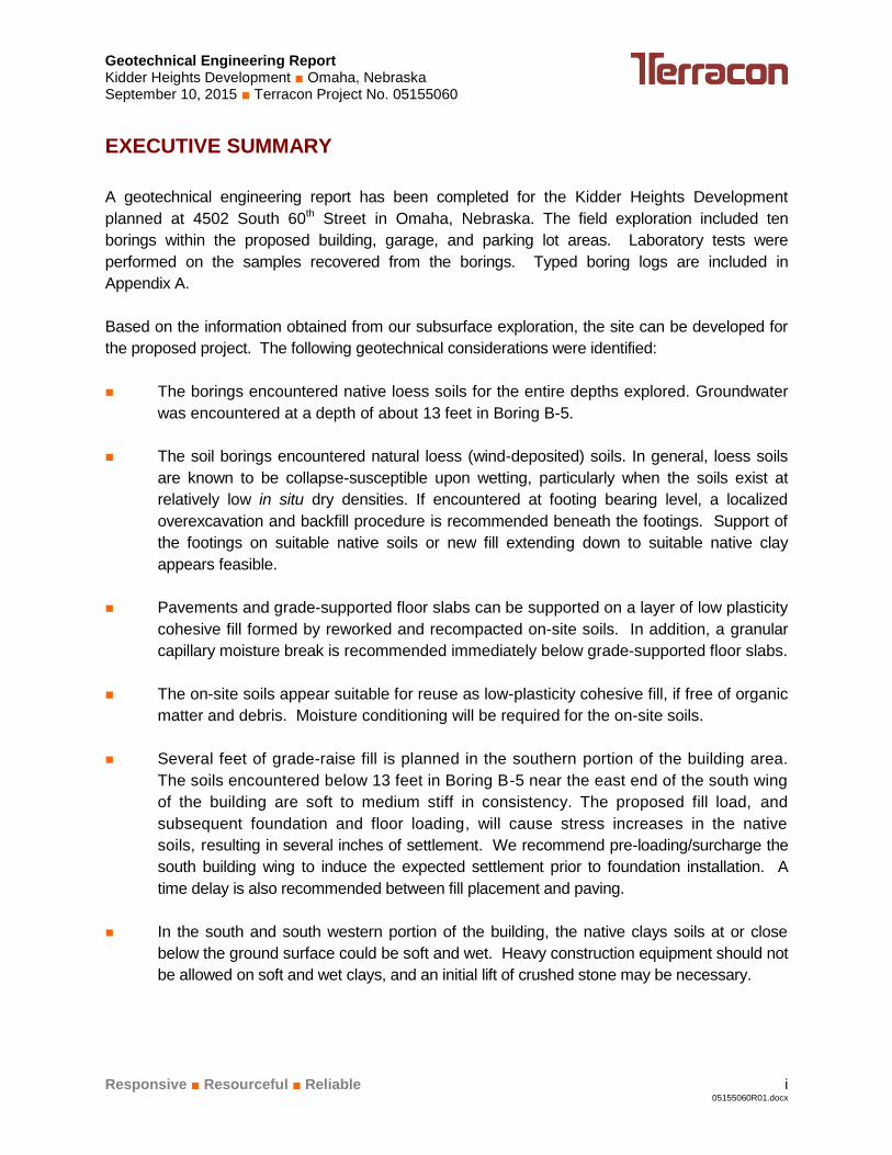
A geotechnical engineering report has been completed for the Kidder Heights Development
planned at 4502 South 60th Street in Omaha, Nebraska. The field exploration included ten
borings within the proposed building, garage, and parking lot areas. Laboratory tests were
performed on the samples recovered from the borings. Typed boring logs are included in
Appendix A.
Based on the information obtained from our subsurface exploration, the site can be developed for
the proposed project. The following geotechnical considerations were identified:
The borings encountered native loess soils for the entire depths explored. Groundwater
was encountered at a depth of about 13 feet in Boring B-5.
The soil borings encountered natural loess (wind-deposited) soils. In general, loess soils
are known to be collapse-susceptible upon wetting, particularly when the soils exist at
relatively low in situ dry densities. If encountered at footing bearing level, a localized
overexcavation and backfill procedure is recommended beneath the footings. Support of
the footings on suitable native soils or new fill extending down to suitable native clay
appears feasible.
Pavements and grade-supported floor slabs can be supported on a layer of low plasticity
cohesive fill formed by reworked and recompacted on-site soils. In addition, a granular
capillary moisture break is recommended immediately below grade-supported floor slabs.
The on-site soils appear suitable for reuse as low-plasticity cohesive fill, if free of organic
matter and debris. Moisture conditioning will be required for the on-site soils.
Several feet of grade-raise fill is planned in the southern portion of the building area.
The soils encountered below 13 feet in Boring B-5 near the east end of the south wing
of the building are soft to medium stiff in consistency. The proposed fill load, and
subsequent foundation and floor loading, will cause stress increases in the native
soils, resulting in several inches of settlement. We recommend pre-loading/surcharge the
south building wing to induce the expected settlement prior to foundation installation. A
time delay is also recommended between fill placement and paving.
In the south and south western portion of the building, the native clays soils at or close
below the ground surface could be soft and wet. Heavy construction equipment should not
be allowed on soft and wet clays, and an initial lift of crushed stone may be necessary.

TABLE OF CONTENTS (CONTINUED)
Resourceful ■ Responsive ■ Reliable 05155060R01.docx
Close monitoring of the construction operations discussed herein will be critical in
achieving the design subgrade and foundation support. We therefore recommend
Terracon be retained to monitor this portion of the work.
This summary should be used in conjunction with the entire report for design purposes. It should
be recognized that details were not included or fully developed in this section, and the report must
be read in its entirety for a comprehensive understanding of the items contained herein. The
section titled GENERAL COMMENTS should be read for an understanding of the report
limitations.

Resourceful ■ Responsive ■ Reliable 1 05155060R01.docx
GEOTECHNICAL ENGINEERING REPORT
KIDDER HEIGHTS DEVELOPMENT
4052 SOUTH 60TH STREET
OMAHA, NEBRASKA
Terracon Project No. 05155060
September 10, 2015
1.0 INTRODUCTION
This report presents the results of our subsurface exploration for the Kidder Heights Development
planned at 4502 South 60th Street in Omaha, Nebraska. The field exploration included ten
borings to depths of approximately 5 to 25 feet below the existing ground surface within the
proposed building, garage, and parking lot areas. The individual boring logs are included in
Appendix A. The boring locations are shown on the Boring Location Plans, also included in
Appendix A.
Our work was completed in general accordance with our proposal agreement no. P05150410
dated May 7, 2015.
The purpose of these services is to provide information and geotechnical engineering
recommendations relative to:
soil conditions footing foundation design and construction
groundwater conditions floor slab design and construction
site preparation and earthwork pavement subgrade preparation
lateral earth pressures and
drainage, cantilever walls
minimum pavement thicknesses
2.0 PROJECT INFORMATION
2.1 Project Description
Item Description
Boring and Site layout Boring Location Plan, Exhibit A-2 and A-3 in Appendix A.
Structures The project will include a 75 unit, three-story building. Garages are
planned along the north property line.
Geotechnical Engineering Report Kidder Heights Development ■ Omaha, Nebraska September 10, 2015 ■ Terracon Project No. 05155060
Responsive ■ Resourceful ■ Reliable 2 05155060R01.docx
Item Description
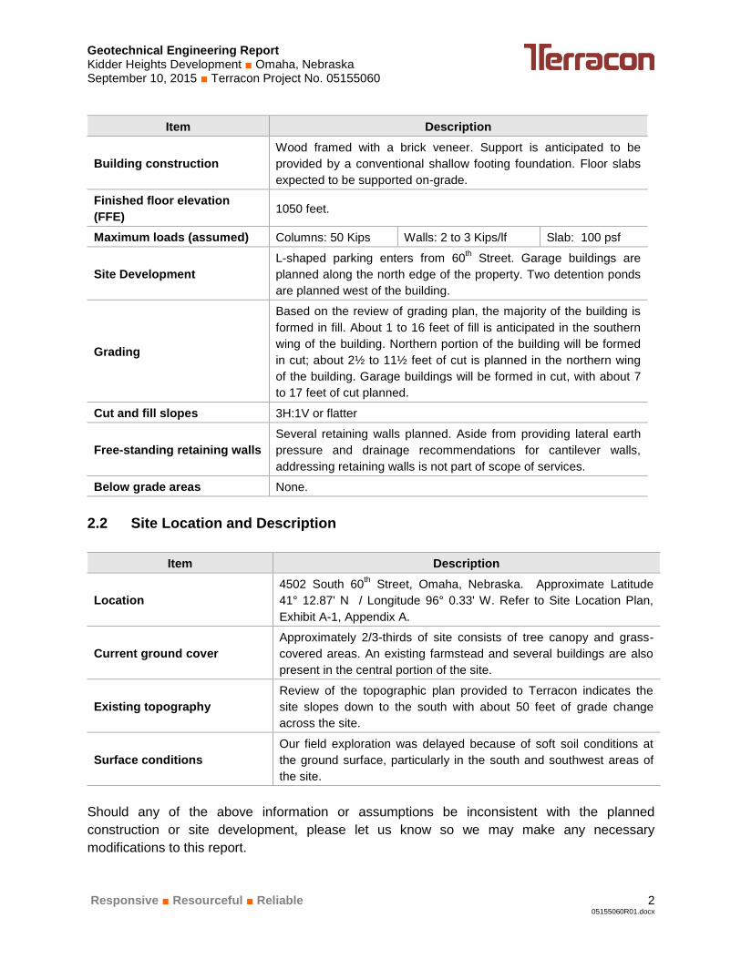
Building construction
Wood framed with a brick veneer. Support is anticipated to be
provided by a conventional shallow footing foundation. Floor slabs
expected to be supported on-grade.
Finished floor elevation
(FFE) 1050 feet.
Maximum loads (assumed) Columns: 50 Kips Walls: 2 to 3 Kips/lf Slab: 100 psf
Site Development
L-shaped parking enters from 60th Street. Garage buildings are
planned along the north edge of the property. Two detention ponds
are planned west of the building.
Grading
Based on the review of grading plan, the majority of the building is
formed in fill. About 1 to 16 feet of fill is anticipated in the southern
wing of the building. Northern portion of the building will be formed
in cut; about 2½ to 11½ feet of cut is planned in the northern wing
of the building. Garage buildings will be formed in cut, with about 7
to 17 feet of cut planned.
Cut and fill slopes 3H:1V or flatter
Free-standing retaining walls
Several retaining walls planned. Aside from providing lateral earth
pressure and drainage recommendations for cantilever walls,
addressing retaining walls is not part of scope of services.
Below grade areas None.
2.2 Site Location and Description
Item Description
Location
4502 South 60th Street, Omaha, Nebraska. Approximate Latitude
41° 12.87' N / Longitude 96° 0.33' W. Refer to Site Location Plan,
Exhibit A-1, Appendix A.
Current ground cover
Approximately 2/3-thirds of site consists of tree canopy and grass-
covered areas. An existing farmstead and several buildings are also
present in the central portion of the site.
Existing topography
Review of the topographic plan provided to Terracon indicates the
site slopes down to the south with about 50 feet of grade change
across the site.
Surface conditions
Our field exploration was delayed because of soft soil conditions at
the ground surface, particularly in the south and southwest areas of
the site.
Should any of the above information or assumptions be inconsistent with the planned
construction or site development, please let us know so we may make any necessary
modifications to this report.

Geotechnical Engineering Report Kidder Heights Development ■ Omaha, Nebraska September 10, 2015 ■ Terracon Project No. 05155060
Responsive ■ Resourceful ■ Reliable 3 05155060R01.docx
3.0 SUBSURFACE CONDITIONS
3.1 Mapped Soil Units
Surface soils at the project site were mapped as part of the effort to develop the Douglas County
NRCS-USDA Soil Survey. According to this document, the Monona series is mapped at the site.
The Monona series consists of very deep, well drained soils formed in loess. These soils have
low to moderate shrink-swell potential and high frost action potential. The seasonal high water
level in these series is noted as greater than about 6 feet below native grade.
The soil profile may have been altered by grading associated with urban construction and
development.
More information is presented in the Soil Survey of Douglas and Sarpy Counties, Nebraska.
3.2 Typical Profile
Based on the results of the borings, we anticipate the subsurface conditions on the project site
can be generalized as follows:
Layer Approximate Depth
to Bottom of Stratum Material Encountered Consistency/Density
Surface: N/A Grass, shallow root zone N/A
Stratum 1
(Loess)
5 to 25-foot
termination depth of all
borings
Lean Clay, Lean to Fat Clay
Stiff to Very Stiff
Medium Stiff to Soft below 13
feet in Boring B-5
Conditions encountered at each boring location are indicated on the individual boring logs.
Additional information is presented on the boring logs in Appendix A. Stratification boundaries on
the boring logs represent the approximate location of changes in soil types; in-situ, the transition
between materials may be gradual.
Variations may occur between soil borings or across the site. Previous grading and construction
may have created additional variations.
3.3 Groundwater
The boreholes were observed while drilling for the presence and level of groundwater. The water
levels observed are noted on the attached boring logs, and are summarized below.

Geotechnical Engineering Report Kidder Heights Development ■ Omaha, Nebraska September 10, 2015 ■ Terracon Project No. 05155060
Responsive ■ Resourceful ■ Reliable 4 05155060R01.docx
Boring Number Depth to groundwater while drilling, ft.
B-5 13
Remaining borings Not encountered
A relatively long period of time is necessary for a groundwater level to develop and stabilize in a
borehole. Longer term monitoring in cased holes or piezometers would be required for a more
accurate evaluation of the groundwater conditions.
Groundwater level fluctuations occur due to seasonal variations in the amount of rainfall, runoff,
river levels and other factors not evident at the time the borings were performed. Therefore,
groundwater levels during construction or at other times in the life of the structure may be higher
or lower than the levels indicated on the boring logs. It is also our experience that perched
water can develop overlying compacted clay fill and overlying dense native clay. The possibility
of groundwater level fluctuations and development of perched water conditions should be
considered when developing the design and construction plans for the project.
4.0 RECOMMENDATIONS FOR DESIGN AND CONSTRUCTION
4.1 Geotechnical Considerations
4.1.1 Low-Density Loess Soils
The soil borings encountered natural loess (wind-deposited) soils. In general, loess soils are
known to be collapse-susceptible upon wetting, particularly when the soils exist at relatively low
in situ dry densities (e.g., less than about 85 pcf). Our borings did not encounter soils with
densities lower than 85 pcf but several samples had densities lower than 90 pcf. Although the
low-density soils have sufficient strength to support the expected foundation loads in their
currently dry condition, low-density loess soils are susceptible to strength loss and collapse upon
wetting, and present a risk of foundation settlement should they become wetted at any time during
the life of the structure. Should dry, collapse-susceptible loess be encountered at footing-bearing
elevation during construction, supporting the footing on at least 2 feet of reworked and
recompacted soil would be appropriate.
Although moisture-sensitive soils may be present below the densified zone, the relatively low
permeability of the densified layer will help reduce the rate of vertical infiltration of surface water
into the underlying moisture-sensitive soils. Replacement of the overexcavated soils as
compacted fill should be performed in accordance with the recommendations outlined in this
report. Even with the recommended soil improvements, additional recommendations are provided
concerning site grading and landscaping to help reduce the potential for surface water infiltration.
Geotechnical Engineering Report Kidder Heights Development ■ Omaha, Nebraska September 10, 2015 ■ Terracon Project No. 05155060
Responsive ■ Resourceful ■ Reliable 5 05155060R01.docx
4.1.2 Proposed Grade Raise
Based on the grading plan provided to us, we anticipate grade raise of about 3 to 16 feet will be
required in the southern building wing. The soils encountered below 13 feet in Boring B-5 are
soft to medium stiff in consistency. The proposed fill load, and subsequent foundation and
floor loading, will cause stress increases in the native soils, resulting in estimated settlement of
about 3 inches. We recommend pre-loading/surcharge the southern wing building to induce the
expected settlement prior to foundation installation. Similarly, we recommend the fill required for
the parking lot east of the building be placed at least 6 to 8 weeks prior to paving. The preloading
process should be monitored with settlement plates, and the construction schedule will need to
accommodate the time interval for preloading. Additional discussion and recommendations are
presented in subsection 4.2.8 Settlement.
4.1.3 Soft Subgrade Conditions
Terracon had difficulty accessing the site during field exploration with a truck-mounted drill rig
due to steep terrain and soft ground conditions. Several unsuccessful trips were made to the
site.
The surficial soils were soft and wet along the south leg of the building. These soils will be at
subgrade level in the southwest portion of the building, and fill is planned over these soils in the
southeast portion of the building. These materials may be unstable under construction
equipment loads. Scarification and drying or subgrade stabilization will be required prior to
placing fill if these soils are wet and soft. Subgrade stabilization could contain installation of a
granular working base.
4.2 Site Preparation and Earthwork
4.2.1 Site Stripping
Stripping of all existing vegetation, organic topsoil, and other materials unsuitable for re-use as
engineered fill should be performed within all cut, fill, paving, and building areas. A typical
stripping depth of about 6 to 9 inches is expected to be adequate in most areas. However, areas
of both deeper and shallower stripping could be encountered. A Terracon geotechnical
representative should help evaluate actual stripping depths at the time of construction. We
recommend that site stripping and subgrade preparation procedures extend at least 5 feet
beyond the building perimeter, and at least 2 feet beyond the edges of the proposed
pavements.
Tree and shrub root systems and any desiccated soils should be thoroughly removed from the
building and pavement areas, and areas to receive fill. An effort should be made to locate
records, plats or photographs indicating the past location of trees or other large vegetation at the
site. In addition, some of the natural soils may have been desiccated by the tree roots. Desiccated
clays present a significant risk of heave if left in-place below foundations or floor slabs. Therefore,

Geotechnical Engineering Report Kidder Heights Development ■ Omaha, Nebraska September 10, 2015 ■ Terracon Project No. 05155060
Responsive ■ Resourceful ■ Reliable 6 05155060R01.docx
any soils desiccated by trees or shrub roots should be thoroughly removed and replaced with low-
plasticity cohesive fill.
Existing foundations, floor slabs, basement walls, cisterns, utilities, and other farmstead
structures should be removed. This process should include removal of existing fill and any
organic topsoil buried by the existing fill. The actual removal depths and lateral extents should
be evaluated by a Terracon representative during construction.
We recommend floor slabs and pavements be underlain by at least 8 inches of low plasticity
cohesive fill formed by reworking and recompacting on-site soils. We recommend pavement
areas be cut and filled to subgrade level during mass grading. Immediately prior to paving, we
recommend the pavement subgrade soils be scarified and recompacted as discussed in
subsection 4.2.3 Structural Fill Compaction Requirements.
In the south and south western portion of the building, the native clays soils at or close below the
ground surface could be soft and wet. Heavy construction equipment should not be allowed on
soft and wet clays, and an initial lift of crushed stone may be necessary. If areas of rutting or other
disturbance develop, the disturbed material should be recompacted or removed and replaced.
Fill placed on a slope steeper than 5H:1V (horizontal to vertical) should be benched into the
slope. A maximum riser height on the order of 2 feet, separated by horizontal steps that are
wide enough to accommodate compaction equipment, is recommended.
Proofrolling is recommended after stripping in areas to receive fill. Proofrolling aids in providing
a firm base for compaction of fill and delineating soft, or disturbed areas that may exist below
subgrade level. Unsuitable areas observed at this time should be improved by scarification and
recompaction or by undercutting and replacement with structural fill. Initially, proof-rolling may
be accomplished with a third- to half-loaded, tandem-axle, dump truck with a gross weight of 15
tons or other equipment providing an equivalent subgrade loading. If the subgrade holds up well
under the initial loading, proofrolling may be attempted with a fully-loaded, tandem-axle, dump
truck with a minimum gross weight of 25 tons or other equipment providing an equivalent
subgrade loading.
The native soils in some of the borings have high moisture contents and are susceptible to
disturbance from construction activity and surface water / seepage. Even where the hand
penetrometer tests indicate these materials may be stiff, we anticipate they will degrade rapidly
under loading from construction activity. The use of either remote equipment (e.g,. backhoes) or
construction equipment with relatively light contact pressures is recommended; heavy
construction traffic should not be allowed. Construction operations in these areas should be
carefully monitored, and restricted if subgrade disturbance becomes apparent. Disturbed soils
should be removed and replaced.

Geotechnical Engineering Report Kidder Heights Development ■ Omaha, Nebraska September 10, 2015 ■ Terracon Project No. 05155060
Responsive ■ Resourceful ■ Reliable 7 05155060R01.docx
Terracon should be retained to monitor stripping, subgrade stability, foundation and existing fill
removal, utility abandonment, site excavation, removal of unsuitable materials, and proofrolling.
Terracon can assist in low-strength native soils that should be undercut and removed, as well as
identifying additional corrective measures for conditions that may become apparent during
construction.
4.2.2 Structural Fill Material Requirements
Structural fill should meet the following material property requirements:
Fill Type 1 USCS Classification Acceptable Location for Placement
Low-plasticity,
cohesive soil
CL
(LL<45 and 10<PI<20) 2
All locations and elevations.
Granular 3
SP, SW, GW Directly below slabs-on-grade.
Drainage Fill 5 SP, SW, GW Free-draining granular fill behind retaining walls.
“Bridge lift” granular 6 SP, SW, GW Stabilizing layer at the soft subgrade locations.
On-Site Soil 4
CL Suitable if meeting the requirements of “Low
Plasticity Cohesive” above.
1. Structural fill should consist of low or moderate plasticity cohesive soils or approved granular materials
that are free of organic matter, debris, and contamination. Frozen material should not be used, and fill
should not be placed on a frozen subgrade. Each proposed fill material type should be sampled and
evaluated by the geotechnical engineer prior to its delivery and/or use.
2. LL = Liquid Limit, PI = Plasticity Index.
3. A material similar to NDOR Crushed Rock for Base Course, with 6% or less fines (material passing the
#200 sieve). Terracon is available to review gradations of proposed materials.
4. Sorting of on-site soils containing debris, organics, etc., will be necessary. Delineation of unsuitable on-
site soils should be performed in the field by a Terracon representative. Moisture conditioning of the on-
site soils is anticipated to be necessary to facilitate compaction.
5. Well-graded, free-draining granular material. A general gradation should be 100% passing the 1½-
inch sieve, about 40 percent passing the No. 10 sieve, and less than 6 percent fines. NDOR 47B
Fine Aggregate For Concrete or approved alternate.
6. Imported. Well-graded, crushed stone or crushed concrete, containing 100 percent passing the 3-inch
sieve and less than 10 percent fines. Crushed concrete can be used but is subject to degradation
under repetitive traffic loads, and so should be used with caution. Terracon can review proposed
materials.
Terracon should be retained to evaluate proposed fill materials, including performing laboratory
tests to evaluate compliance with the project specifications. We can also review test results
provided by the contractor.

Geotechnical Engineering Report Kidder Heights Development ■ Omaha, Nebraska September 10, 2015 ■ Terracon Project No. 05155060
Responsive ■ Resourceful ■ Reliable 8 05155060R01.docx
4.2.3 Structural Fill Compaction Requirements
Item Description
Fill Lift Thickness 1
8-inches or less in loose thickness
Compaction Requirements 2, 3, 5
Upper 8 inches of pavement
subgrade
Below footings and all other
locations
98% of the materials maximum standard Proctor dry
density (ASTM D 698)
95% of the materials maximum standard Proctor dry
density (ASTM D 698).
Moisture Content - Cohesive Soil
Within the range of -2 to +3 percent of the optimum
moisture content value as determined by the
standard Proctor test at the time of placement and
compaction.
Moisture Content - Granular Material 4 Workable moisture levels
1. Thinner lifts may be required in confined areas or within excavations. Or when hand-operated
compaction equipment is used.
2. We recommend engineered fill be tested for moisture content and compaction during
placement. Should the results of the in-place density tests indicate the specified moisture or
compaction limits have not been met, the area represented by the test should be reworked and
retested as required until the specified moisture and compaction requirements are achieved.
3. Consideration can be given to compacting all fill below pavements to 95% during mass
grading. Immediately prior to paving, we recommend that the subgrade below exterior
pavements be rough-graded as needed, and then scarified and recompacted. We recommend
this process include scarifying the subgrade to a depth of about 9 inches, moisture conditioning
the scarified soil to within -2 to +3 percent of the material’s optimum, and compacting the
scarified soil to at least 98%. Scarified soils which cannot be recompacted to this degree
should be undercut and replaced with stable material.
4. Specifically, moisture levels should be maintained low enough to allow for satisfactory
compaction to be achieved without the cohesionless fill material pumping when proofrolled or
containing excess water (ponding).
5. Where a granular layer fill is placed over a subgrade composed of wet or soft clay, care should be
taken not to overcompact the initial lift of fill. Overcompaction can cause subgrade disturbance
and loss of strength of the underlying subgrade. In these areas, we recommend that the
compaction be accomplished with 2 or 3 mutually perpendicular passes of each thin lift with light-
eight vibratory compaction equipment. Instead of a strict compaction requirement, consideration
should be given to using visual evaluation of material stability using factors such as surface
stability and aggregate interlock when evaluating compaction and performance of the granular
material.
Terracon should be retained to monitor fill placement and to perform field density tests as each lift
of fill is place in order to evaluate compliance with the design requirements. We should be retained
to observe and test floor slab and pavement subgrades immediately prior to paving.
Geotechnical Engineering Report Kidder Heights Development ■ Omaha, Nebraska September 10, 2015 ■ Terracon Project No. 05155060
Responsive ■ Resourceful ■ Reliable 9 05155060R01.docx
4.2.4 Utility Trench Backfill
All trench excavations should be made with sufficient working space to permit construction
including backfill placement and compaction. If utility trenches are backfilled with relatively clean
granular material, they should be capped with at least 18 inches of cohesive fill in non-pavement
areas to reduce the infiltration and conveyance of surface water through the trench backfill. We
also recommend that all utility trenches be plugged with a clay core at locations where they enter
under the new building to prevent the utility trench from being a route for water to get into the new
building structure.
4.2.5 Construction Considerations
Any areas of standing surface water should be drained as far in advance of construction as
possible.
The native clays encountered in the borings will be sensitive to disturbance from construction
activity and water seepage. If precipitation occurs immediately prior to or during construction, the
near-surface clay soils could increase in moisture content and become more susceptible to
disturbance. Construction activity should be monitored, and should be curtailed if the construction
activity is causing subgrade disturbance. A Terracon representative can help with monitoring and
developing recommendations to avoid subgrade disturbance.
Surface water should not be allowed to pond on the site and soak into the soil during construction.
Construction staging should provide drainage of surface water and precipitation away from the
building and pavement areas. Any water that collects over or adjacent to construction areas
should be promptly removed, along with any softened or disturbed soils. Surface water control in
the form of sloping surfaces, drainage ditches and trenches, and sump pits and pumps will be
important to avoid ponding and associated delays due to precipitation and seepage.
Upon completion of filling and grading, care should be taken to maintain the subgrade moisture
content prior to construction of floor slabs and pavements. Construction traffic over the
completed subgrade should be avoided to the extent practical. The site should also be graded
to prevent ponding of surface water on the prepared subgrades or in excavations. If the
subgrade should become frozen, desiccated, saturated, or disturbed, the affected material
should be removed or these materials should be scarified, moisture conditioned, and
recompacted prior to floor slab and pavement construction.
As a minimum, all temporary excavations should be sloped or braced as required by
Occupational Safety and Health Administration (OSHA) regulations to provide stability and safe
working conditions. Temporary excavations will probably be required during grading operations.
The grading contractor, by his contract, is usually responsible for designing and constructing
stable, temporary excavations and should shore, slope or bench the sides of the excavations as
required, to maintain stability of both the excavation sides and bottom. All excavations should
Geotechnical Engineering Report Kidder Heights Development ■ Omaha, Nebraska September 10, 2015 ■ Terracon Project No. 05155060
Responsive ■ Resourceful ■ Reliable 10 05155060R01.docx
comply with applicable local, state and federal safety regulations, including the current OSHA
Excavation and Trench Safety Standards.
4.2.6 Exterior Grading
Poor site drainage and ponding of surface water can increase the potential for frost heave or
settlement. Excessive moisture can reduce the soil's bearing capacity and contribute to slab and
pavement settlement and cracking.
Finished grading slopes should promote drainage away from the building and pavement areas to
help prevent post-construction wetting of the bearing soils. We recommend final grades for seeded
and landscaped areas be sloped at least 5 percent within 10 feet around the buildings to direct
surface water well away from the buildings. We recommend cohesive backfill be placed in utility
trenches and adjacent to building foundations and curbs, and this fill be compacted to at least 95
percent of standard Proctor maximum dry density to help prevent surface water infiltration. Roof
drains should be extended to discharge on pavements or in lawn areas more than 5 feet from the
buildings. Pavements or sidewalks installed adjacent to the building should slope away from the
building at a grade of 2% or more.
Overwatering of grass or landscaping vegetation is a significant source of water, and should be
avoided near the buildings and pavements. Sprinkler heads should be adjusted to miss the
exterior building wall and pavements. Automated watering systems should be programmed to not
run after natural rain events, and to not overwater. Any utility leaks should be promptly repaired.
Lining the bottom of irrigated planter areas along the building with an impermeable moisture
barrier, and installing tile lines leading to gravity outlets or sump pits and pumps, would also help to
control surface water that infiltrates into these features.
4.2.7 Slope Maintenance
Large cut and fill slopes are planned. A detailed stability evaluation of the cut and fill slopes is
beyond our current scope, and would require additional field exploration and laboratory testing.
We understand the cut slopes will generally have inclinations of 3H:1V or flatter. It is our
experience that slopes in the dry loess soils flatter than about 3H:1V would not expected to
experience deep-seated slope failure. Slopes of 3H:1V are anticipated to be stable in the native
loess soils where seasonal groundwater seepage does not exit the proposed slope and surface
water infiltration is limited above the slope by including proper drainage.
The planned cuts slopes are expected to encounter native loess soils. Flowing water and soft,
saturated soils are not expected to be encountered within the proposed depths of cut in the loess
soils. However, seepage can occur seasonally and after periods of heavy or prolonged rainfall.
The seepage could cause minor, long-term maintenance concerns with the slope, such as erosion
and localized slumps or soft areas. These surface developments typically do not jeopardize the
Geotechnical Engineering Report Kidder Heights Development ■ Omaha, Nebraska September 10, 2015 ■ Terracon Project No. 05155060
Responsive ■ Resourceful ■ Reliable 11 05155060R01.docx
deep seated stability of the slope, but could mar the surface of the slope and, if allowed to
progress, could eventually affect the property behind the top of the cut slope.
Subsurface drains can be used to intercept the seepage from seasonally wet areas before it can
exit the cut face and cause surface movements. Cut slope conditions should be observed by
Terracon personnel during construction. The need for subsurface drains should be determined
based on observations after excavation of the slope. We recommend that the project budget
include contingency funds to install these drains.
The clay soils at this site have a high silt content. As a result, slopes exposing or formed of this
material are highly susceptible to surface erosion, sediment transport and sloughing, and will be
difficult to maintain. Surface runoff should be diverted away from the slopes. A series of benches
can be installed to break the slope into distinct units, and to help control surface water and any
areas of localized instability. Erosion protection will be required. If a vegetative cover is planned,
temporary erosion protection may be required until the vegetation can be established.
4.2.8 Settlement
4.2.8.1 Settlement Discussion
Based on the grading plan provided to us, we anticipate grade raise of about 3 to 16 feet will be
required in the southern wing of the building area. The soils encountered below 13 feet in
Boring B-5 are soft to medium stiff in consistency. The proposed fill load, and subsequent
foundation and floor loading, will cause stress increases in the native soils, resulting in
estimated settlement of up to about 3 inches. We recommend pre-loading/surcharge in the
southern wing of the building area to induce the expected settlement prior to foundation
installation. The preloading process should be monitored with settlement plates, and the
construction schedule will need to accommodate the time interval for preloading. Similarly, we
recommend the fill required for the parking lot east of the building be placed at least 6 to 8 weeks
prior to paving.
4.2.8.2 Preload Fill and Surcharge Fill Placement
To preload, all permanent structural fill should be placed up to finished subgrade elevation in
the planned building and to a distance extending at least 20 feet beyond the building
perimeter. The permanent fill should be placed and compacted according to the
recommendations presented in subsection 4.2 Site Preparation and Earthwork.
Placement of additional surcharge fill is recommended to compensate for building and floor
loads. We recommend the surcharge fill extend to the 3 feet height in the building area and at
least 10 feet beyond the building perimeter. The surcharge fill can be placed in lifts 12
inches thick and tracked into place with loaded scrapers or dump trucks. A minimum
compaction criterion is not required, but we recommend the as placed surcharge fill have a
minimum in situ wet unit weight of 100 pcf. The top of the surcharge fill should be sloped to

Geotechnical Engineering Report Kidder Heights Development ■ Omaha, Nebraska September 10, 2015 ■ Terracon Project No. 05155060
Responsive ■ Resourceful ■ Reliable 12 05155060R01.docx
drain to reduce moisture infiltration. The edges of the surcharge should be sloped at 3H:1V
or flatter within the building footprint, but may be steeper where extended beyond the building
footprint.
4.2.8.3 Settlement Monitoring
After placement of the permanent fill and prior to placement of surcharge fill, survey
monuments should be installed for settlement monitoring. We recommend a minimum of two
monuments. The monuments should consist of 2-foot square steel plates firmly embedded on the
permanent fill, with metal riser pipe coupled to the top of the settlement plate and extending above
the preload fill height. Plastic pipe should be installed around the steel riser pipes. Care should
be taken not to disturb the monuments during preload fill and surcharge fill placement. A
monument which is damaged or disturbed should be repaired or replaced immediately.
We recommend surveying the elevations of the settlement monuments to the nearest 100th
of a foot, and the elevation of the top of the adjacent preload fill and surcharge fill to the
nearest 10th of a foot, according to the following schedule:
Time Period Monitoring Schedule
At Time of Monument Seating Initial Readings
During Preload Fill and Surcharge Fill Placement Daily
For two weeks following fill placement Three times per week
Between Two and Four Weeks Following Fill Placement Two times per week
More Than Four Weeks Following Fill Placement, if required Once per week
The monitoring data should be submitted to Terracon for analysis and evaluation of when
construction may proceed. A settlement period of about 6 to 8 weeks is estimated to achieve
adequate consolidation of the compressible layers. This is only an estimate based on our
experience with projects of this type, the soil conditions observed, and the test results. Other
factors affecting the effective drainage path and permeability of the soils may reduce the time
for the settlement to occur. We anticipate at least 4 weeks of settlement data will be required
after surcharge fill placement, before we can begin evaluation of eventual total settlements and
refinement of our time frame estimates.
4.3 Spread Footing Foundations
4.3.1 Design Recommendations
Based on the soil information from borings, low density, dry, collapse-susceptible loess may be
encountered at footing-bearing elevation during construction at isolated locations. Where
encountered, or supporting the footing on at least 2 feet of reworked and recompacted soil is
recommended.
Geotechnical Engineering Report Kidder Heights Development ■ Omaha, Nebraska September 10, 2015 ■ Terracon Project No. 05155060
Responsive ■ Resourceful ■ Reliable 13 05155060R01.docx
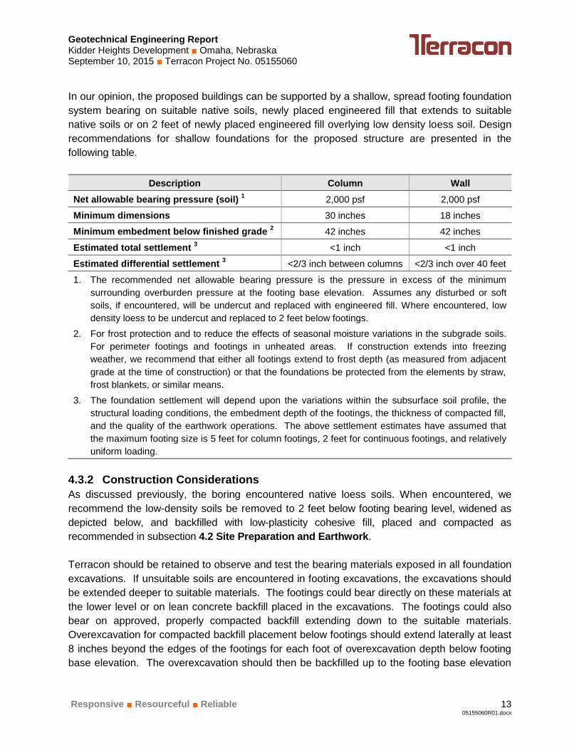
In our opinion, the proposed buildings can be supported by a shallow, spread footing foundation
system bearing on suitable native soils, newly placed engineered fill that extends to suitable
native soils or on 2 feet of newly placed engineered fill overlying low density loess soil. Design
recommendations for shallow foundations for the proposed structure are presented in the
following table.
Description Column Wall
Net allowable bearing pressure (soil) 1
2,000 psf 2,000 psf
Minimum dimensions 30 inches 18 inches
Minimum embedment below finished grade 2 42 inches 42 inches
Estimated total settlement 3 <1 inch <1 inch
Estimated differential settlement 3 <2/3 inch between columns <2/3 inch over 40 feet
1. The recommended net allowable bearing pressure is the pressure in excess of the minimum
surrounding overburden pressure at the footing base elevation. Assumes any disturbed or soft
soils, if encountered, will be undercut and replaced with engineered fill. Where encountered, low
density loess to be undercut and replaced to 2 feet below footings.
2. For frost protection and to reduce the effects of seasonal moisture variations in the subgrade soils.
For perimeter footings and footings in unheated areas. If construction extends into freezing
weather, we recommend that either all footings extend to frost depth (as measured from adjacent
grade at the time of construction) or that the foundations be protected from the elements by straw,
frost blankets, or similar means.
3. The foundation settlement will depend upon the variations within the subsurface soil profile, the
structural loading conditions, the embedment depth of the footings, the thickness of compacted fill,
and the quality of the earthwork operations. The above settlement estimates have assumed that
the maximum footing size is 5 feet for column footings, 2 feet for continuous footings, and relatively
uniform loading.
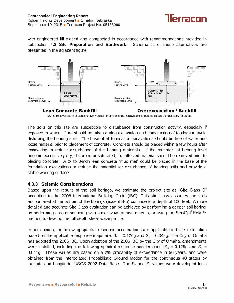
4.3.2 Construction Considerations
As discussed previously, the boring encountered native loess soils. When encountered, we
recommend the low-density soils be removed to 2 feet below footing bearing level, widened as
depicted below, and backfilled with low-plasticity cohesive fill, placed and compacted as
recommended in subsection 4.2 Site Preparation and Earthwork.
Terracon should be retained to observe and test the bearing materials exposed in all foundation
excavations. If unsuitable soils are encountered in footing excavations, the excavations should
be extended deeper to suitable materials. The footings could bear directly on these materials at
the lower level or on lean concrete backfill placed in the excavations. The footings could also
bear on approved, properly compacted backfill extending down to the suitable materials.
Overexcavation for compacted backfill placement below footings should extend laterally at least
8 inches beyond the edges of the footings for each foot of overexcavation depth below footing
base elevation. The overexcavation should then be backfilled up to the footing base elevation
Geotechnical Engineering Report Kidder Heights Development ■ Omaha, Nebraska September 10, 2015 ■ Terracon Project No. 05155060
Responsive ■ Resourceful ■ Reliable 14 05155060R01.docx
with engineered fill placed and compacted in accordance with recommendations provided in
subsection 4.2 Site Preparation and Earthwork. Schematics of these alternatives are
presented in the adjacent figure.
The soils on this site are susceptible to disturbance from construction activity, especially if
exposed to water. Care should be taken during excavation and construction of footings to avoid
disturbing the bearing soils. The base of all foundation excavations should be free of water and
loose material prior to placement of concrete. Concrete should be placed within a few hours after
excavating to reduce disturbance of the bearing materials. If the materials at bearing level
become excessively dry, disturbed or saturated, the affected material should be removed prior to
placing concrete. A 2- to 3-inch lean concrete “mud mat” could be placed in the base of the
foundation excavations to reduce the potential for disturbance of bearing soils and provide a
stable working surface.
4.3.3 Seismic Considerations
Based upon the results of the soil borings, we estimate the project site as “Site Class D”
according to the 2006 International Building Code (IBC). This site class assumes the soils
encountered at the bottom of the borings (except B-5) continue to a depth of 100 feet. A more
detailed and accurate Site Class evaluation can be achieved by performing a deeper soil boring,
by performing a cone sounding with shear wave measurements, or using the SeisOpt®ReMi™
method to develop the full depth shear wave profile.
In our opinion, the following spectral response accelerations are applicable to this site location
based on the applicable response maps are: Ss = 0.126g and S1 = 0.042g. The City of Omaha
has adopted the 2006 IBC. Upon adoption of the 2006 IBC by the City of Omaha, amendments
were installed, including the following spectral response accelerations: Ss = 0.125g and S1 =
0.041g. These values are based on a 2% probability of exceedance in 50 years, and were
obtained from the Interpolated Probabilistic Ground Motion for the continuous 48 states by
Latitude and Longitude, USGS 2002 Data Base. The Ss and S1 values were developed for a
Geotechnical Engineering Report Kidder Heights Development ■ Omaha, Nebraska September 10, 2015 ■ Terracon Project No. 05155060
Responsive ■ Resourceful ■ Reliable 15 05155060R01.docx
Site Class B, and are used in conjunction with coefficients based on site class to determine the
maximum acceleration, Sm1 and Sms.
4.4 Floor Slab
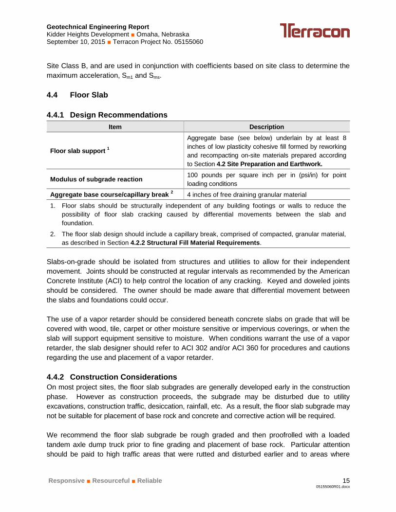
4.4.1 Design Recommendations
Item Description
Floor slab support 1
Aggregate base (see below) underlain by at least 8
inches of low plasticity cohesive fill formed by reworking
and recompacting on-site materials prepared according
to Section 4.2 Site Preparation and Earthwork.
Modulus of subgrade reaction 100 pounds per square inch per in (psi/in) for point
loading conditions
Aggregate base course/capillary break 2 4 inches of free draining granular material
1. Floor slabs should be structurally independent of any building footings or walls to reduce the
possibility of floor slab cracking caused by differential movements between the slab and
foundation.
2. The floor slab design should include a capillary break, comprised of compacted, granular material,
as described in Section 4.2.2 Structural Fill Material Requirements.
Slabs-on-grade should be isolated from structures and utilities to allow for their independent
movement. Joints should be constructed at regular intervals as recommended by the American
Concrete Institute (ACI) to help control the location of any cracking. Keyed and doweled joints
should be considered. The owner should be made aware that differential movement between
the slabs and foundations could occur.
The use of a vapor retarder should be considered beneath concrete slabs on grade that will be
covered with wood, tile, carpet or other moisture sensitive or impervious coverings, or when the
slab will support equipment sensitive to moisture. When conditions warrant the use of a vapor
retarder, the slab designer should refer to ACI 302 and/or ACI 360 for procedures and cautions
regarding the use and placement of a vapor retarder.
4.4.2 Construction Considerations
On most project sites, the floor slab subgrades are generally developed early in the construction
phase. However as construction proceeds, the subgrade may be disturbed due to utility
excavations, construction traffic, desiccation, rainfall, etc. As a result, the floor slab subgrade may
not be suitable for placement of base rock and concrete and corrective action will be required.
We recommend the floor slab subgrade be rough graded and then proofrolled with a loaded
tandem axle dump truck prior to fine grading and placement of base rock. Particular attention
should be paid to high traffic areas that were rutted and disturbed earlier and to areas where

Geotechnical Engineering Report Kidder Heights Development ■ Omaha, Nebraska September 10, 2015 ■ Terracon Project No. 05155060
Responsive ■ Resourceful ■ Reliable 16 05155060R01.docx
backfilled trenches are located. Areas where unsuitable conditions are located should be repaired
by removing and replacing the affected material with properly compacted fill. All floor slab
subgrade areas should be moisture conditioned and properly compacted to the recommendations
in this report immediately prior to placement of the aggregate base course and concrete.
4.5 Lateral Earth Pressures
4.5.1 Design
The lateral earth pressure recommendations given in this section are applicable to the design of
rigid retaining walls subject to slight rotation, such as cantilever, or gravity type concrete walls.
These recommendations are not applicable to the design of modular block - geogrid reinforced
backfill walls (also termed MSE walls). Recommendations covering these types of wall systems
are beyond the scope of services for this assignment. However, we would be pleased to
develop a proposal for evaluation and design of such wall systems upon request.
Reinforced concrete walls with unbalanced backfill levels on opposite sides should be designed
for earth pressures at least equal to those indicated in the following table. Earth pressures will
be influenced by structural design of the walls, conditions of wall restraint, methods of
construction and/or compaction and the strength of the materials being restrained. Two wall
restraint conditions are shown. Active earth pressure is commonly used for design of
free-standing cantilever retaining walls and assumes wall movement. The "at-rest" condition
assumes no wall movement. The recommended design lateral earth pressures do not include a
factor of safety and do not provide for possible hydrostatic pressure on the walls.

Geotechnical Engineering Report Kidder Heights Development ■ Omaha, Nebraska September 10, 2015 ■ Terracon Project No. 05155060
Responsive ■ Resourceful ■ Reliable 17 05155060R01.docx
Earth Pressure Coefficients
Earth Pressure
Conditions
Coefficient for
Backfill Type
Equivalent Fluid
Density (pcf)
Surcharge
Pressure, p1 (psf)
Earth Pressure,
p2 (psf)
Active (Ka) Granular - 0.33
Lean Clay - 0.42
40
50
(0.33)S
(0.42)S
(40)H
(50)H
At-Rest (Ko) Granular - 0.46
Lean Clay - 0.50
55
60
(0.46)S
(0.50)S
(55)H
(60)H
Passive (Kp) Granular - 3.0
Lean Clay - 2.4
360
290
---
---
---
---
Applicable conditions to the above include:
For active earth pressure, wall must rotate about base, with top lateral movements of
about 0.002 H to 0.004 H, where H is wall height
For passive earth pressure to develop, wall must move horizontally to mobilize
resistance
Uniform surcharge, where S is surcharge pressure
In-situ soil backfill weight a maximum of 120 pcf
Horizontal backfill, compacted between 95 and 98 percent of standard Proctor maximum
dry density
No hydrostatic pressure acting on wall
No loading from compaction equipment
No loading from nearby footings or slabs
No dynamic loading
Finished grade is horizontal both behind wall and at toe of wall
No safety factor included in soil parameters
Ignore passive pressure in frost zone
Backfill placed against structures should consist of granular soils or low plasticity cohesive soils.
For the granular values to be valid, the granular backfill must extend out from the base of the wall
at an angle of at least 45 and 60 degrees from vertical for the active/at-rest and passive cases,
respectively. To calculate the resistance to sliding, a value of 0.4 should be used as the ultimate
coefficient of friction between the footing and the underlying soil.
Footings and other loads located adjacent to walls may have a significant effect on lateral
pressures. Placement of footings in wall backfill should be avoided unless structural analyses
are performed to evaluate the resulting loads and effects on the wall. To avoid excessive lateral
wall loads, heavy compaction equipment should not be operated within a distance out from new
or existing walls equal to the height above the base of the wall.

Geotechnical Engineering Report Kidder Heights Development ■ Omaha, Nebraska September 10, 2015 ■ Terracon Project No. 05155060
Responsive ■ Resourceful ■ Reliable 18 05155060R01.docx
4.5.2 Drainage Systems
A perforated rigid plastic or metal drain line should be installed behind the retaining walls to prevent
hydrostatic loading on the walls. The invert of a drain line around the retaining walls should be at
least 6 inches below the slab on the low side of the wall. The drain line should be sloped to provide
positive gravity drainage to a
sump or other suitable outlet.
The drain line should be
surrounded by free-draining
granular material graded to
prevent the intrusion of soil
fines into the granular
material or the intrusion of the
granular material into the
drain pipe perforations.
Alternatively, a coarse, clean,
free-draining granular
material could be used to
surround the pipe if this
material is encapsulated with
suitable filter fabric.
At least a 2-foot wide section of free-draining granular fill is recommended for backfill above the
drain line and adjacent to the wall and should extend up to within 2 feet of exterior grade. A
prefabricated drainage structure may be used above a drain line and the surrounding filter, in lieu
of free-draining granular fill. A prefabricated drainage structure is a plastic drainage core or mesh
which is covered with filter fabric to prevent soil intrusion, and is fastened to the wall prior to placing
backfill.
If this is not possible to install a drain along the base of the wall, then combined hydrostatic and
lateral earth pressures should be calculated using the following values:
Active Condition 1 At-Rest Condition
1
Clay Backfill 90 pcf 100 pcf
Granular Backfill 85 pcf 95 pcf
1. These pressures do not include the influence of surcharge,
equipment, or floor loading, which should be added.
4.6 Exterior Pavements
4.6.1 Subgrades
The pavements should be underlain by at least 8 inches of reworked and recompacted low
plasticity cohesive fill prepared in accordance with the recommendations presented in subsection
Geotechnical Engineering Report Kidder Heights Development ■ Omaha, Nebraska September 10, 2015 ■ Terracon Project No. 05155060
Responsive ■ Resourceful ■ Reliable 19 05155060R01.docx
4.2 Site Preparation and Earthwork. Typical construction in the Eastern Nebraska area is not
to place a granular base below pavements for this type of facility. Rather, the pavements are
supported directly on the cohesive subgrade soils. If the project design results in a granular base
being installed below pavements, Terracon should be retained to provide additional
recommendations. For example, subdrains are recommended in conjunction with a granular base
to prevent water from ponding in the granular base.
4.6.2 Design and Thickness Recommendations
We recommend the following pavement sections:
Standard Duty Pavements: For parking areas subjected to low volumes of automobile
traffic, a full-depth ACC section having a total thickness of at least 6 inches, or a PCC
pavement section having a thickness of at least 5 inches, is recommended.
Heavy-Duty Pavements: Entry drives and truck driveways require increased pavement
thicknesses. A minimum 7-inch thick ACC section, or a minimum 6-inch thick PCC
section, is recommended in these areas.
Truck Pads: A minimum 7-inch thick PCC section is recommended for aprons in truck
loading docks, delivery truck parking areas, and refuse pick-up areas. Such areas
should have a concrete section wide enough to accommodate the vehicles that would use
it.
Terracon has observed dishing in some parking lots surfaced with ACC. Dishing is usually
observed in frequently-used parking stalls (such as near the front of the building), and occurs
under the wheel footprint in these stalls. The use of higher grade asphaltic cement such as
PG70-28, or surfacing these areas with PCC, is recommended. The dishing is exacerbated by
factors such as irrigated islands or planter areas, sheet surface drainage to the front of the
building, and placing the ACC directly on a compacted clay subgrade. The use of lower grade
asphalt cement, such as PG64-22 is relatively common in this area and may be considered, but
would provide lower reliability against rutting and creeping during warm weather.
Minimum surface course thicknesses of 2 inches in automobile areas and 3 inches in driveways
are recommended for asphaltic cement concrete pavement sections. An ACC base course
thickness of 4 inches is recommended.
We recommend that ACC and PCC pavement specifications reference Sections 400 and 500,
respectively, of the City of Omaha Standard Specifications for Public Works Construction, 2003
Edition. We recommend a surface mix type CMR for ACC pavements and mix type L65 for
PCC pavements.

Geotechnical Engineering Report Kidder Heights Development ■ Omaha, Nebraska September 10, 2015 ■ Terracon Project No. 05155060
Responsive ■ Resourceful ■ Reliable 20 05155060R01.docx
A formal pavement design has not been completed for this project. The above recommended
pavement sections are typical minimum values and thicker pavement sections could be used to
reduce maintenance and extend the expected service life of the pavements. Periodic maintenance
will also extend the service life of the pavements and should include patching and repair of
deteriorated areas, crack sealing, and surface sealing. We recommend that a California Bearing
Ratio (CBR) test and a formal pavement design be completed if unusually high vehicle loads or
frequencies are anticipated.
4.6.3 Construction Considerations
Construction scheduling often involves grading and paving by separate contractors and can
involve a time lapse between the end of grading operations and the commencement of paving.
Disturbance, desiccation or wetting of the subgrade soils between grading and paving can result
in deterioration of the previously completed subgrade. A non-uniform subgrade can result in
poor pavement performance and local failures relatively soon after pavements are constructed.
We recommend the moisture content and density of the subgrade be evaluated within two days
prior to commencement of actual paving operations. A proof roll using heavy equipment similar
to that required for pavement construction is also recommended to verify subgrade stability for
pavement construction. Scarification and recompaction may also be required.
Areas not in compliance with the required ranges of moisture or density should be moisture
conditioned and recompacted. If significant precipitation occurs after the evaluation or if the
surface becomes disturbed, the subgrade condition should be reviewed by Terracon personnel
immediately prior to paving.
4.6.4 Drainage and Maintenance Considerations
Preventing subgrade saturation is an important factor in maintaining the subgrade strength. Water
allowed to pond on or next to pavements could saturate the subgrade and cause premature
pavement deterioration. Positive surface drainage should be provided away from the edges of
paved areas, and all pavements should be sloped to provide rapid surface drainage. Pavements
should drain toward the edges rather than the center, and perimeter subsurface drains should be
installed next to irrigated planters or other areas where surface water could pond.
4.7 Exterior Slabs
The clayey soils on this site are considered highly frost susceptible. Grade-supported exterior
slabs should be expected to heave. The amount of heave may be reduced by providing surface
drainage away from the building and slabs and toward the site storm drainage system. Structural
stoops are recommended adjacent to exterior doors and other movement-sensitive exterior slabs.
Consideration should be made to installing drain-tile around the perimeter of exterior slabs that
connect directly to the storm drainage system to help further reduce the potential for frost heave.
Geotechnical Engineering Report Kidder Heights Development ■ Omaha, Nebraska September 10, 2015 ■ Terracon Project No. 05155060
Responsive ■ Resourceful ■ Reliable 21 05155060R01.docx
Consideration should also be given to extending structural stoops or a zone of non-frost
susceptible fill to include the front sidewalks, ADA parking stalls, and pathways connecting the
ADA stalls with the entrances. It is our opinion that placing non-frost susceptible material in large
areas under exterior pavements and sidewalks would be exceedingly expensive and an unusual
design and construction procedure in this area. We should be contacted to provide additional
recommendations should consideration be given to placing non-frost-susceptible (granular)
material in large areas.
5.0 GENERAL COMMENTS
Terracon should be retained to review the final design plans and specifications so comments
can be made regarding interpretation and implementation of our geotechnical recommendations
in the design and specifications. Terracon also should be retained to provide observation and
testing services during grading, excavation, foundation construction and other earth-related
construction phases of the project.
The analysis and recommendations presented in this report are based upon the data obtained
from the borings performed at the indicated locations and from other information discussed in
this report. This report does not reflect variations that may occur between borings, across the
site, or due to the modifying effects of construction or weather. The nature and extent of such
variations may not become evident until during or after construction. If variations appear, we
should be immediately notified so that further evaluation and supplemental recommendations
can be provided.
The scope of services for this project does not include either specifically or by implication any
environmental or biological (e.g., mold, fungi, bacteria) assessment of the site or identification or
prevention of pollutants, hazardous materials or conditions. If the owner is concerned about the
potential for such contamination or pollution, other studies should be undertaken.
This report has been prepared for the exclusive use of our client for specific application to the
project discussed and has been prepared in accordance with generally accepted geotechnical
engineering practices. No warranties, either express or implied, are intended or made. Site
safety, excavation support, and dewatering requirements are the responsibility of others. In the
event that changes in the nature, design, or location of the project as outlined in this report are
planned, the conclusions and recommendations contained in this report shall not be considered
valid unless Terracon reviews the changes and either verifies or modifies the conclusions of this
report in writing.

Responsive ■ Resourceful ■ Reliable
05155060R01.docx
APPENDIX A
FIELD EXPLORATION

SITE LOCATION PLAN
Kidder Heights Development4502 S 60th St
Omaha, NE
TOPOGRAPHIC MAP IMAGE COURTESY OF THE U.S. GEOLOGICAL SURVEYQUADRANGLES INCLUDE: RALSTON, NE (1/1/1984) and OMAHA SOUTH, NE (1/1/1994).
15080 A CircleOmaha, NE 68144
05155060Project Manager:
Drawn by:
Checked by:
Approved by:
GKA
MDR
MDR
1”=24,000 SF
05155060
9/2/2015
Project No.
Scale:
File Name:
Date:A-1
ExhibitGKA

BORING LOCATION PLAN
Kidder Heights Development4502 S 60th St
Omaha, NE15080 A Circle
Omaha, NE 68144
DIAGRAM IS FOR GENERAL LOCATION ONLY, AND ISNOT INTENDED FOR CONSTRUCTION PURPOSES
05155060
AERIAL PHOTOGRAPHY PROVIDEDBY MICROSOFT BING MAPS
GKA
MDR
MDR
AS SHOWN
05155060
9/2/2015
Scale:
A-2
ExhibitProject Manager:
Drawn by:
Checked by:
Approved by:
Project No.
File Name:
Date:
GKA

BORING LOCATION PLAN
KIDDER HEIGHTS DEVELOPMENT4502 SOUTH 60TH STREET
OMAHA, NEBRASKAA-3
15080 A Circle Omaha, Nebraska 68144
PH. (402) 330-2202 FAX. (402) 330-7606
05155060
9/2/2015
GKA
GKA
MDR
MDR
N.T.S.
Project Manager:
Drawn by:
Checked by:
Approved by:
Project No.
Scale:
File Name:
Date:
Exhibit
05155060BPLANDIAGRAM IS FOR GENERAL LOCATION ONLY, AND IS NOT
INTENDED FOR CONSTRUCTION PURPOSES
- Approximate Boring Location
B-1B-2
B-3
B-4
B-5
B-8
B-7
Source: Kidder Heights, LLC.
B-6
B-10
B-9
Geotechnical Engineering Report Kidder Heights Development ■ Omaha, Nebraska September 10, 2015 ■ Terracon Project No. 05155060
Responsive ■ Resourceful ■ Reliable
A-4
05155060R01.docx
Field Exploration Description
The soil borings were laid out by Terracon personnel using a hand-held GPS unit. GPS
coordinates and elevations were obtained at each location using a hand-held GPS unit with a
vertical accuracy of about ½-foot and a lateral accuracy of about 1 foot. The approximate boring
locations are shown on the Boring Location Plan, Exhibit A-2 and A-3, Appendix A. The locations
and elevations should be considered accurate only to the degree implied by the means and
methods used to define them.
The borings were drilled with a truck-mounted rotary-drilling rig using continuous-flight, solid-stem
augers to advance the boreholes. Representative samples of the soil profile were obtained using
thin-walled tube sampling procedures. The thin-walled tube sampling procedure consisted of
hydraulically pushing 3-inch outside diameter (OD) seamless steel Shelby tubes with a sharp
cutting edge into the bottom of the borehole to obtain a relatively undisturbed sample of cohesive
soils. The samples were tagged for identification, sealed, and taken to the laboratory for testing and
classification.
A field log of each boring was prepared by the drill crew. Each log included visual classifications of
the materials encountered during drilling as well as the driller's interpretation of the subsurface
conditions between samples. The boring logs included with this report represent an interpretation
of the field logs and include modifications based on the laboratory test results and further
examination of the samples by the project geotechnical engineer.

5500(HP)
6500(HP)
4500(HP)
4500(HP)
7000(HP)
7000(HP)
24
21
21
19
18
16
94
100
102
102
102
108
1054
1049
1037
2
7
6
4
3
4
3.0
8.0
20.0
Grass, root zone at surfaceLEAN CLAY (CL), trace sand, trace roots, dark brown, very stiff
LEAN CLAY (CL), trace sand, brown, very stiff
LEAN CLAY (CL), trace sand, light brown, very stiff
Boring Terminated at 20 Feet
Hammer Type: AutomaticStratification lines are approximate. In-situ, the transition may be gradual.
GR
AP
HIC
LO
G
TH
IS B
OR
ING
LO
G IS
NO
T V
ALI
D IF
SE
PA
RA
TE
D F
RO
M O
RIG
INA
L R
EP
OR
T.
GE
O S
MA
RT
LO
G-N
O W
ELL
051
550
60 L
OG
S.G
PJ
TE
RR
AC
ON
2015
.GD
T 9
/9/1
5
4502 S. 60th Street Omaha, NESITE:
Page 1 of 1
Advancement Method:Continuous Flight Auger
Abandonment Method:Boring backfilled with soil cuttings upon completion.
15080 A CircleOmaha, Nebraska
Notes:
Project No.: 05155060
Drill Rig: #96
Boring Started: 8/25/2015
BORING LOG NO. B-1Kidder Heights, LLC.CLIENT:Omaha, NE
Driller: J. McGargill
Boring Completed: 8/25/2015
Exhibit: A-5
See Exhibit A-3 for description of field procedures.
See Appendix B for description of laboratoryprocedures and additional data (if any).
See Appendix C for explanation of symbols andabbreviations.
PROJECT: Kidder Heights Development
LAB
OR
AT
OR
YT
OR
VA
NE
/HP
(ps
f)
UN
CO
NF
INE
DC
OM
PR
ES
SIV
ES
TR
EN
GT
H (
psf)
WA
TE
RC
ON
TE
NT
(%
)
DR
Y U
NIT
WE
IGH
T (
pcf)
ATTERBERGLIMITS
LL-PL-PISurface Elev.: 1057 (Ft.)
ELEVATION (Ft.)
SA
MP
LE T
YP
E
WA
TE
R L
EV
EL
OB
SE
RV
AT
ION
S
DE
PT
H (
Ft.)
5
10
15
20
RE
CO
VE
RY
(In
.)
DEPTH
LOCATION
Latitude: 41.2151° Longitude: -96.0054°
See Exhibit A-2
Not Encountered, While Drilling
WATER LEVEL OBSERVATIONS
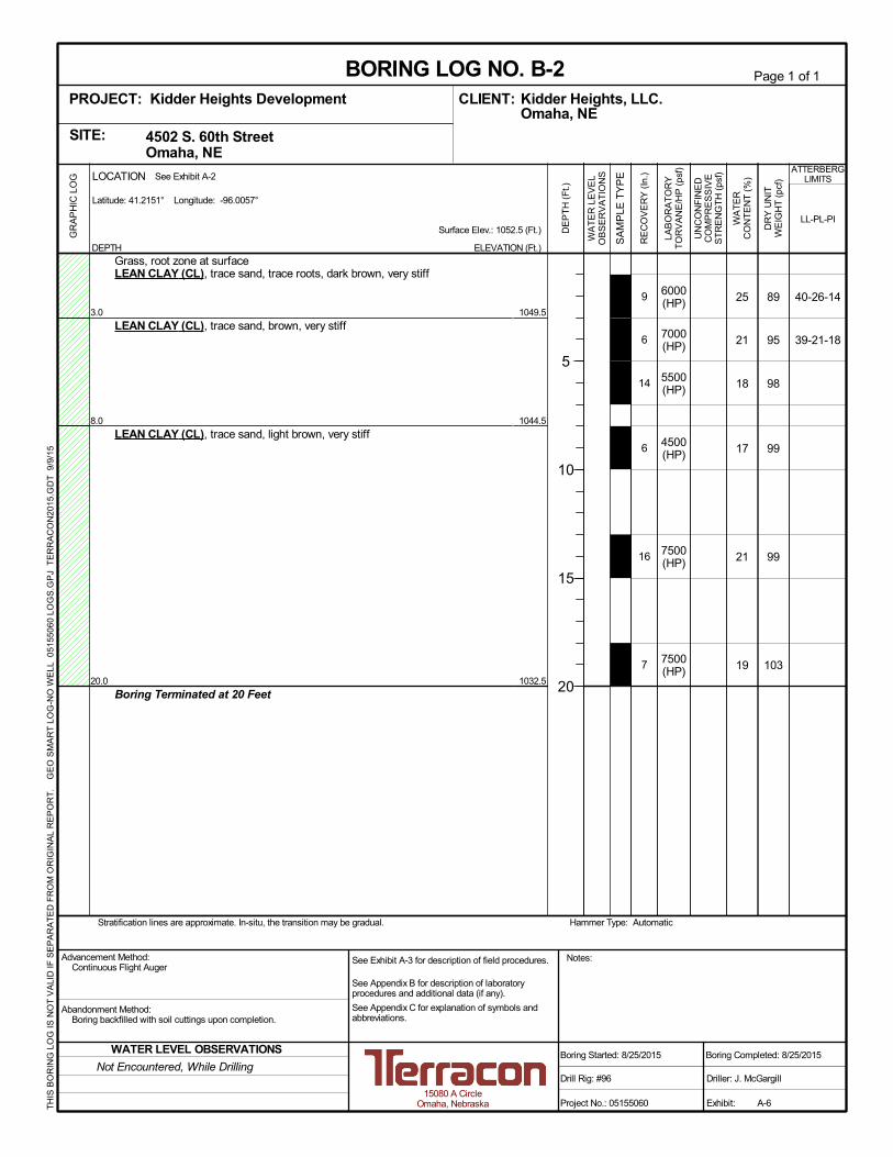
6000(HP)
7000(HP)
5500(HP)
4500(HP)
7500(HP)
7500(HP)
25
21
18
17
21
19
89
95
98
99
99
103
40-26-14
39-21-18
1049.5
1044.5
1032.5
9
6
14
6
16
7
3.0
8.0
20.0
Grass, root zone at surfaceLEAN CLAY (CL), trace sand, trace roots, dark brown, very stiff
LEAN CLAY (CL), trace sand, brown, very stiff
LEAN CLAY (CL), trace sand, light brown, very stiff
Boring Terminated at 20 Feet
Hammer Type: AutomaticStratification lines are approximate. In-situ, the transition may be gradual.
GR
AP
HIC
LO
G
TH
IS B
OR
ING
LO
G IS
NO
T V
ALI
D IF
SE
PA
RA
TE
D F
RO
M O
RIG
INA
L R
EP
OR
T.
GE
O S
MA
RT
LO
G-N
O W
ELL
051
550
60 L
OG
S.G
PJ
TE
RR
AC
ON
2015
.GD
T 9
/9/1
5
4502 S. 60th Street Omaha, NESITE:
Page 1 of 1
Advancement Method:Continuous Flight Auger
Abandonment Method:Boring backfilled with soil cuttings upon completion.
15080 A CircleOmaha, Nebraska
Notes:
Project No.: 05155060
Drill Rig: #96
Boring Started: 8/25/2015
BORING LOG NO. B-2Kidder Heights, LLC.CLIENT:Omaha, NE
Driller: J. McGargill
Boring Completed: 8/25/2015
Exhibit: A-6
See Exhibit A-3 for description of field procedures.
See Appendix B for description of laboratoryprocedures and additional data (if any).
See Appendix C for explanation of symbols andabbreviations.
PROJECT: Kidder Heights Development
LAB
OR
AT
OR
YT
OR
VA
NE
/HP
(ps
f)
UN
CO
NF
INE
DC
OM
PR
ES
SIV
ES
TR
EN
GT
H (
psf)
WA
TE
RC
ON
TE
NT
(%
)
DR
Y U
NIT
WE
IGH
T (
pcf)
ATTERBERGLIMITS
LL-PL-PISurface Elev.: 1052.5 (Ft.)
ELEVATION (Ft.)
SA
MP
LE T
YP
E
WA
TE
R L
EV
EL
OB
SE
RV
AT
ION
S
DE
PT
H (
Ft.)
5
10
15
20
RE
CO
VE
RY
(In
.)
DEPTH
LOCATION
Latitude: 41.2151° Longitude: -96.0057°
See Exhibit A-2
Not Encountered, While Drilling
WATER LEVEL OBSERVATIONS
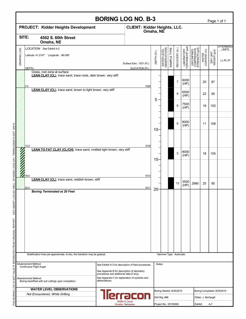
6000(HP)
6500(HP)
7500(HP)
8000(HP)
8000(HP)
3500(HP) 2980
25
22
19
11
18
25
87
95
102
108
105
95
1028
1018
1013
1011
7
8
6
6
5
13
3.0
13.0
18.0
20.0
Grass, root zone at surfaceLEAN CLAY (CL), trace sand, trace roots, dark brown, very stiff
LEAN CLAY (CL), trace sand, brown to light brown, very stiff
LEAN TO FAT CLAY (CL/CH), trace sand, mottled light brown, very stiff
LEAN CLAY (CL), trace sand, reddish-brown, stiff
Boring Terminated at 20 Feet
Hammer Type: AutomaticStratification lines are approximate. In-situ, the transition may be gradual.
GR
AP
HIC
LO
G
TH
IS B
OR
ING
LO
G IS
NO
T V
ALI
D IF
SE
PA
RA
TE
D F
RO
M O
RIG
INA
L R
EP
OR
T.
GE
O S
MA
RT
LO
G-N
O W
ELL
051
550
60 L
OG
S.G
PJ
TE
RR
AC
ON
2015
.GD
T 9
/9/1
5
4502 S. 60th Street Omaha, NESITE:
Page 1 of 1
Advancement Method:Continuous Flight Auger
Abandonment Method:Boring backfilled with soil cuttings upon completion.
15080 A CircleOmaha, Nebraska
Notes:
Project No.: 05155060
Drill Rig: #96
Boring Started: 8/25/2015
BORING LOG NO. B-3Kidder Heights, LLC.CLIENT:Omaha, NE
Driller: J. McGargill
Boring Completed: 8/25/2015
Exhibit: A-7
See Exhibit A-3 for description of field procedures.
See Appendix B for description of laboratoryprocedures and additional data (if any).
See Appendix C for explanation of symbols andabbreviations.
PROJECT: Kidder Heights Development
LAB
OR
AT
OR
YT
OR
VA
NE
/HP
(ps
f)
UN
CO
NF
INE
DC
OM
PR
ES
SIV
ES
TR
EN
GT
H (
psf)
WA
TE
RC
ON
TE
NT
(%
)
DR
Y U
NIT
WE
IGH
T (
pcf)
ATTERBERGLIMITS
LL-PL-PISurface Elev.: 1031 (Ft.)
ELEVATION (Ft.)
SA
MP
LE T
YP
E
WA
TE
R L
EV
EL
OB
SE
RV
AT
ION
S
DE
PT
H (
Ft.)
5
10
15
20
RE
CO
VE
RY
(In
.)
DEPTH
LOCATION
Latitude: 41.2147° Longitude: -96.006°
See Exhibit A-2
Not Encountered, While Drilling
WATER LEVEL OBSERVATIONS
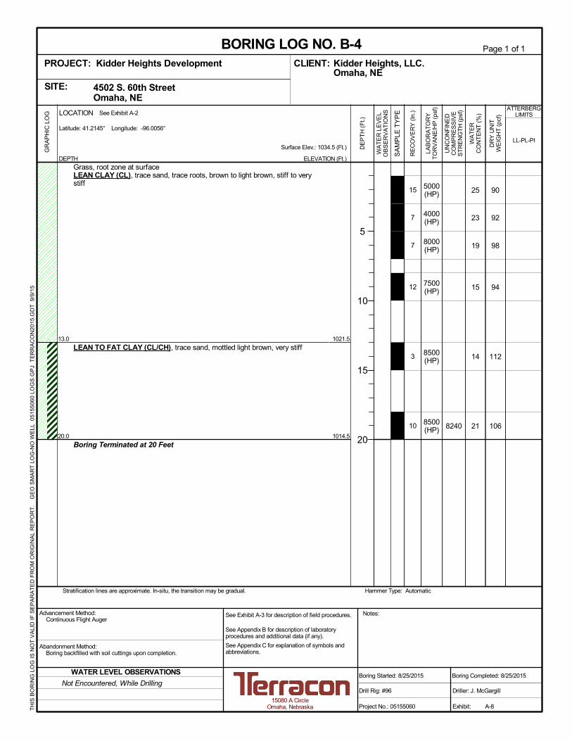
5000(HP)
4000(HP)
8000(HP)
7500(HP)
8500(HP)
8500(HP) 8240
25
23
19
15
14
21
90
92
98
94
112
106
1021.5
1014.5
15
7
7
12
3
10
13.0
20.0
Grass, root zone at surfaceLEAN CLAY (CL), trace sand, trace roots, brown to light brown, stiff to verystiff
LEAN TO FAT CLAY (CL/CH), trace sand, mottled light brown, very stiff
Boring Terminated at 20 Feet
Hammer Type: AutomaticStratification lines are approximate. In-situ, the transition may be gradual.
GR
AP
HIC
LO
G
TH
IS B
OR
ING
LO
G IS
NO
T V
ALI
D IF
SE
PA
RA
TE
D F
RO
M O
RIG
INA
L R
EP
OR
T.
GE
O S
MA
RT
LO
G-N
O W
ELL
051
550
60 L
OG
S.G
PJ
TE
RR
AC
ON
2015
.GD
T 9
/9/1
5
4502 S. 60th Street Omaha, NESITE:
Page 1 of 1
Advancement Method:Continuous Flight Auger
Abandonment Method:Boring backfilled with soil cuttings upon completion.
15080 A CircleOmaha, Nebraska
Notes:
Project No.: 05155060
Drill Rig: #96
Boring Started: 8/25/2015
BORING LOG NO. B-4Kidder Heights, LLC.CLIENT:Omaha, NE
Driller: J. McGargill
Boring Completed: 8/25/2015
Exhibit: A-8
See Exhibit A-3 for description of field procedures.
See Appendix B for description of laboratoryprocedures and additional data (if any).
See Appendix C for explanation of symbols andabbreviations.
PROJECT: Kidder Heights Development
LAB
OR
AT
OR
YT
OR
VA
NE
/HP
(ps
f)
UN
CO
NF
INE
DC
OM
PR
ES
SIV
ES
TR
EN
GT
H (
psf)
WA
TE
RC
ON
TE
NT
(%
)
DR
Y U
NIT
WE
IGH
T (
pcf)
ATTERBERGLIMITS
LL-PL-PISurface Elev.: 1034.5 (Ft.)
ELEVATION (Ft.)
SA
MP
LE T
YP
E
WA
TE
R L
EV
EL
OB
SE
RV
AT
ION
S
DE
PT
H (
Ft.)
5
10
15
20
RE
CO
VE
RY
(In
.)
DEPTH
LOCATION
Latitude: 41.2145° Longitude: -96.0056°
See Exhibit A-2
Not Encountered, While Drilling
WATER LEVEL OBSERVATIONS

3000(HP)
4000(HP)
4000(HP)
2000(HP)
1000(HP)
500(HP)
28
26
25
26
32
32
85
91
94
92
88
88
1029
1024
1012
6
6
6
8
15
16
3.0
8.0
20.0
Grass, root zone at surfaceLEAN CLAY (CL), trace sand, trace roots, dark brown, stiff
LEAN CLAY (CL), trace sand, brown, stiff
LEAN CLAY (CL), trace sand, light brown, medium stiff
Soft below about 13 ft
Boring Terminated at 20 Feet
Hammer Type: AutomaticStratification lines are approximate. In-situ, the transition may be gradual.
GR
AP
HIC
LO
G
TH
IS B
OR
ING
LO
G IS
NO
T V
ALI
D IF
SE
PA
RA
TE
D F
RO
M O
RIG
INA
L R
EP
OR
T.
GE
O S
MA
RT
LO
G-N
O W
ELL
051
550
60 L
OG
S.G
PJ
TE
RR
AC
ON
2015
.GD
T 9
/9/1
5
4502 S. 60th Street Omaha, NESITE:
Page 1 of 1
Advancement Method:Continuous Flight Auger
Abandonment Method:Boring backfilled with soil cuttings upon completion.
15080 A CircleOmaha, Nebraska
Notes:
Project No.: 05155060
Drill Rig: #96
Boring Started: 8/25/2015
BORING LOG NO. B-5Kidder Heights, LLC.CLIENT:Omaha, NE
Driller: J. McGargill
Boring Completed: 8/25/2015
Exhibit: A-9
See Exhibit A-3 for description of field procedures.
See Appendix B for description of laboratoryprocedures and additional data (if any).
See Appendix C for explanation of symbols andabbreviations.
PROJECT: Kidder Heights Development
LAB
OR
AT
OR
YT
OR
VA
NE
/HP
(ps
f)
UN
CO
NF
INE
DC
OM
PR
ES
SIV
ES
TR
EN
GT
H (
psf)
WA
TE
RC
ON
TE
NT
(%
)
DR
Y U
NIT
WE
IGH
T (
pcf)
ATTERBERGLIMITS
LL-PL-PISurface Elev.: 1032 (Ft.)
ELEVATION (Ft.)
SA
MP
LE T
YP
E
WA
TE
R L
EV
EL
OB
SE
RV
AT
ION
S
DE
PT
H (
Ft.)
5
10
15
20
RE
CO
VE
RY
(In
.)
DEPTH
LOCATION
Latitude: 41.2141° Longitude: -96.0051°
See Exhibit A-2
13 ft., While Drilling
WATER LEVEL OBSERVATIONS
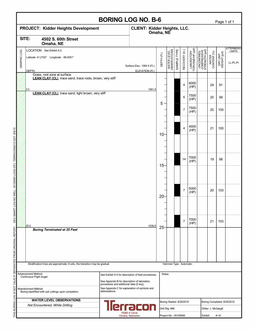
6000(HP)
7500(HP)
7500(HP)
4500(HP)
7000(HP)
5000(HP)
7000(HP)
24
20
20
21
19
20
21
91
99
100
100
98
103
103
1061.5
1039.5
4
6
7
4
14
7
7
3.0
25.0
Grass, root zone at surfaceLEAN CLAY (CL), trace sand, trace roots, brown, very stiff
LEAN CLAY (CL), trace sand, light brown, very stiff
Boring Terminated at 25 Feet
Hammer Type: AutomaticStratification lines are approximate. In-situ, the transition may be gradual.
GR
AP
HIC
LO
G
TH
IS B
OR
ING
LO
G IS
NO
T V
ALI
D IF
SE
PA
RA
TE
D F
RO
M O
RIG
INA
L R
EP
OR
T.
GE
O S
MA
RT
LO
G-N
O W
ELL
051
550
60 L
OG
S.G
PJ
TE
RR
AC
ON
2015
.GD
T 9
/9/1
5
4502 S. 60th Street Omaha, NESITE:
Page 1 of 1
Advancement Method:Continuous Flight Auger
Abandonment Method:Boring backfilled with soil cuttings upon completion.
15080 A CircleOmaha, Nebraska
Notes:
Project No.: 05155060
Drill Rig: #96
Boring Started: 8/25/2015
BORING LOG NO. B-6Kidder Heights, LLC.CLIENT:Omaha, NE
Driller: J. McGargill
Boring Completed: 8/25/2015
Exhibit: A-10
See Exhibit A-3 for description of field procedures.
See Appendix B for description of laboratoryprocedures and additional data (if any).
See Appendix C for explanation of symbols andabbreviations.
PROJECT: Kidder Heights Development
LAB
OR
AT
OR
YT
OR
VA
NE
/HP
(ps
f)
UN
CO
NF
INE
DC
OM
PR
ES
SIV
ES
TR
EN
GT
H (
psf)
WA
TE
RC
ON
TE
NT
(%
)
DR
Y U
NIT
WE
IGH
T (
pcf)
ATTERBERGLIMITS
LL-PL-PISurface Elev.: 1064.5 (Ft.)
ELEVATION (Ft.)
SA
MP
LE T
YP
E
WA
TE
R L
EV
EL
OB
SE
RV
AT
ION
S
DE
PT
H (
Ft.)
5
10
15
20
25
RE
CO
VE
RY
(In
.)
DEPTH
LOCATION
Latitude: 41.2152° Longitude: -96.0051°
See Exhibit A-2
Not Encountered, While Drilling
WATER LEVEL OBSERVATIONS

4000(HP)
4500(HP)
7000(HP)
5500(HP)
7000(HP)
6000(HP)
25
21
19
18
20
21
90
96
97
102
102
101
1047.5
1032.5
1030.5
4
5
7
5
7
10
3.0
18.0
20.0
Grass, root zone at surfaceLEAN CLAY (CL), trace sand, trace roots, brown, stiff
LEAN CLAY (CL), trace sand, light brown, very stiff
LEAN CLAY (CL), trace sand, reddish-brown, very stiff
Boring Terminated at 20 Feet
Hammer Type: AutomaticStratification lines are approximate. In-situ, the transition may be gradual.
GR
AP
HIC
LO
G
TH
IS B
OR
ING
LO
G IS
NO
T V
ALI
D IF
SE
PA
RA
TE
D F
RO
M O
RIG
INA
L R
EP
OR
T.
GE
O S
MA
RT
LO
G-N
O W
ELL
051
550
60 L
OG
S.G
PJ
TE
RR
AC
ON
2015
.GD
T 9
/9/1
5
4502 S. 60th Street Omaha, NESITE:
Page 1 of 1
Advancement Method:Continuous Flight Auger
Abandonment Method:Boring backfilled with soil cuttings upon completion.
15080 A CircleOmaha, Nebraska
Notes:
Project No.: 05155060
Drill Rig: #96
Boring Started: 8/25/2015
BORING LOG NO. B-7Kidder Heights, LLC.CLIENT:Omaha, NE
Driller: J. McGargill
Boring Completed: 8/25/2015
Exhibit: A-11
See Exhibit A-3 for description of field procedures.
See Appendix B for description of laboratoryprocedures and additional data (if any).
See Appendix C for explanation of symbols andabbreviations.
PROJECT: Kidder Heights Development
LAB
OR
AT
OR
YT
OR
VA
NE
/HP
(ps
f)
UN
CO
NF
INE
DC
OM
PR
ES
SIV
ES
TR
EN
GT
H (
psf)
WA
TE
RC
ON
TE
NT
(%
)
DR
Y U
NIT
WE
IGH
T (
pcf)
ATTERBERGLIMITS
LL-PL-PISurface Elev.: 1050.5 (Ft.)
ELEVATION (Ft.)
SA
MP
LE T
YP
E
WA
TE
R L
EV
EL
OB
SE
RV
AT
ION
S
DE
PT
H (
Ft.)
5
10
15
20
RE
CO
VE
RY
(In
.)
DEPTH
LOCATION
Latitude: 41.2151° Longitude: -96.0061°
See Exhibit A-2
Not Encountered, While Drilling
WATER LEVEL OBSERVATIONS

7500(HP)
7500(HP)
14
16
101
871046
8
9
5.0
Grass, root zone at surfaceLEAN CLAY (CL), trace sand, trace roots, light brown, very stiff
Boring Terminated at 5 Feet
Hammer Type: AutomaticStratification lines are approximate. In-situ, the transition may be gradual.
GR
AP
HIC
LO
G
TH
IS B
OR
ING
LO
G IS
NO
T V
ALI
D IF
SE
PA
RA
TE
D F
RO
M O
RIG
INA
L R
EP
OR
T.
GE
O S
MA
RT
LO
G-N
O W
ELL
051
550
60 L
OG
S.G
PJ
TE
RR
AC
ON
2015
.GD
T 9
/9/1
5
4502 S. 60th Street Omaha, NESITE:
Page 1 of 1
Advancement Method:Continuous Flight Auger
Abandonment Method:Boring backfilled with soil cuttings upon completion.
15080 A CircleOmaha, Nebraska
Notes:
Project No.: 05155060
Drill Rig: #96
Boring Started: 8/25/2015
BORING LOG NO. B-8Kidder Heights, LLC.CLIENT:Omaha, NE
Driller: J. McGargill
Boring Completed: 8/25/2015
Exhibit: A-12
See Exhibit A-3 for description of field procedures.
See Appendix B for description of laboratoryprocedures and additional data (if any).
See Appendix C for explanation of symbols andabbreviations.
PROJECT: Kidder Heights Development
LAB
OR
AT
OR
YT
OR
VA
NE
/HP
(ps
f)
UN
CO
NF
INE
DC
OM
PR
ES
SIV
ES
TR
EN
GT
H (
psf)
WA
TE
RC
ON
TE
NT
(%
)
DR
Y U
NIT
WE
IGH
T (
pcf)
ATTERBERGLIMITS
LL-PL-PISurface Elev.: 1051 (Ft.)
ELEVATION (Ft.)
SA
MP
LE T
YP
E
WA
TE
R L
EV
EL
OB
SE
RV
AT
ION
S
DE
PT
H (
Ft.)
5
RE
CO
VE
RY
(In
.)
DEPTH
LOCATION
Latitude: 41.2148° Longitude: -96.005°
See Exhibit A-2
Not Encountered, While Drilling
WATER LEVEL OBSERVATIONS

3000(HP)
4500(HP)
22
22
91
941034
3
7
5.0
Grass, root zone at surfaceLEAN CLAY (CL), trace sand, trace roots, light brown, stiff to very stiff
Boring Terminated at 5 Feet
Hammer Type: AutomaticStratification lines are approximate. In-situ, the transition may be gradual.
GR
AP
HIC
LO
G
TH
IS B
OR
ING
LO
G IS
NO
T V
ALI
D IF
SE
PA
RA
TE
D F
RO
M O
RIG
INA
L R
EP
OR
T.
GE
O S
MA
RT
LO
G-N
O W
ELL
051
550
60 L
OG
S.G
PJ
TE
RR
AC
ON
2015
.GD
T 9
/9/1
5
4502 S. 60th Street Omaha, NESITE:
Page 1 of 1
Advancement Method:Continuous Flight Auger
Abandonment Method:Boring backfilled with soil cuttings upon completion.
15080 A CircleOmaha, Nebraska
Notes:
Project No.: 05155060
Drill Rig: 96
Boring Started: 5/22/2015
BORING LOG NO. B-9Kidder Heights, LLC.CLIENT:Omaha, NE
Driller: J. McGargill
Boring Completed: 5/22/2015
Exhibit: A-13
See Exhibit A-3 for description of field procedures.
See Appendix B for description of laboratoryprocedures and additional data (if any).
See Appendix C for explanation of symbols andabbreviations.
PROJECT: Kidder Heights Development
LAB
OR
AT
OR
YT
OR
VA
NE
/HP
(ps
f)
UN
CO
NF
INE
DC
OM
PR
ES
SIV
ES
TR
EN
GT
H (
psf)
WA
TE
RC
ON
TE
NT
(%
)
DR
Y U
NIT
WE
IGH
T (
pcf)
ATTERBERGLIMITS
LL-PL-PISurface Elev.: 1039 (Ft.)
ELEVATION (Ft.)
SA
MP
LE T
YP
E
WA
TE
R L
EV
EL
OB
SE
RV
AT
ION
S
DE
PT
H (
Ft.)
5
RE
CO
VE
RY
(In
.)
DEPTH
LOCATION
Latitude: 41.2146° Longitude: -96.0055°
See Exhibit A-2
Not Encountered, While Drilling
WATER LEVEL OBSERVATIONS

5500(HP)
3500(HP)
23
25
96
93
1037.5
1035.5
2
3
3.0
5.0
Grass, root zone at surfaceLEAN CLAY, trace sand, trace roots, mottled brown, very stiff
LEAN CLAY (CL), trace sand, mottled light brown, stiff
Boring Terminated at 5 Feet
Hammer Type: AutomaticStratification lines are approximate. In-situ, the transition may be gradual.
GR
AP
HIC
LO
G
TH
IS B
OR
ING
LO
G IS
NO
T V
ALI
D IF
SE
PA
RA
TE
D F
RO
M O
RIG
INA
L R
EP
OR
T.
GE
O S
MA
RT
LO
G-N
O W
ELL
051
550
60 L
OG
S.G
PJ
TE
RR
AC
ON
2015
.GD
T 9
/9/1
5
4502 S. 60th Street Omaha, NESITE:
Page 1 of 1
Advancement Method:Continuous Flight Auger
Abandonment Method:Boring backfilled with soil cuttings upon completion.
15080 A CircleOmaha, Nebraska
Notes:
Project No.: 05155060
Drill Rig: 96
Boring Started: 5/22/2015
BORING LOG NO. B-10Kidder Heights, LLC.CLIENT:Omaha, NE
Driller: J. McGargill
Boring Completed: 5/22/2015
Exhibit: A-14
See Exhibit A-3 for description of field procedures.
See Appendix B for description of laboratoryprocedures and additional data (if any).
See Appendix C for explanation of symbols andabbreviations.
PROJECT: Kidder Heights Development
LAB
OR
AT
OR
YT
OR
VA
NE
/HP
(ps
f)
UN
CO
NF
INE
DC
OM
PR
ES
SIV
ES
TR
EN
GT
H (
psf)
WA
TE
RC
ON
TE
NT
(%
)
DR
Y U
NIT
WE
IGH
T (
pcf)
ATTERBERGLIMITS
LL-PL-PISurface Elev.: 1040.5 (Ft.)
ELEVATION (Ft.)
SA
MP
LE T
YP
E
WA
TE
R L
EV
EL
OB
SE
RV
AT
ION
S
DE
PT
H (
Ft.)
5
RE
CO
VE
RY
(In
.)
DEPTH
LOCATION
Latitude: 41.2144° Longitude: -96.005°
See Exhibit A-2
Not Encountered, While Drilling
WATER LEVEL OBSERVATIONS

Responsive ■ Resourceful ■ Reliable
05155060R01.docx
APPENDIX B
LABORATORY TESTING

Geotechnical Engineering Report Kidder Heights Development ■ Omaha, Nebraska September 10, 2015 ■ Terracon Project No. 05155060
Responsive ■ Resourceful ■ Reliable B-1 05155060R01.docx
Laboratory Testing
Water content tests (ASTM D2216) were performed on the samples. Density determinations
(ASTM D7263) were performed on most of the thin-walled tube samples, and unconfined
compression tests (ASTM D2166) were performed on some of the thin-walled tube samples. The
unconfined compressive strength of most of the samples was estimated with a hand penetrometer
test. In addition, Atterberg limits tests (ASTM D4318) were performed on two samples. Results of
these laboratory tests are provided on the boring logs.
The samples were classified in the laboratory based on visual observation, texture and plasticity
(ASTM D2488). Additional laboratory testing could be performed to more accurately classify the
samples. The soil descriptions presented on the boring logs for native soils are in accordance
with our enclosed General Notes and Unified Soil Classification System (USCS, ASTM D2487).
The estimated group symbol for the USCS is also shown on the boring logs for native soils, and
a brief description of the Unified System is included in this report.
Procedural standards noted above are for reference to methodology in general. In some cases,
variations to methods are applied as a result of local practice or professional judgment.

Responsive ■ Resourceful ■ Reliable
05155060R01.docx
APPENDIX C
SUPPORTING DOCUMENTS
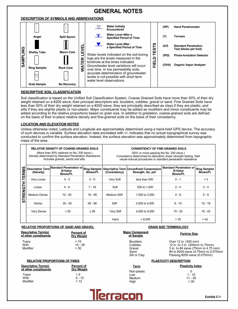
TraceWithModifier
Water Level Aftera Specified Period of Time
GRAIN SIZE TERMINOLOGYRELATIVE PROPORTIONS OF SAND AND GRAVEL
TraceWithModifier
Standard Penetration orN-Value
Blows/Ft.
Descriptive Term(Consistency)
Loose
Very Stiff
Exhibit C-1
Standard Penetration orN-Value
Blows/Ft.
Ring SamplerBlows/Ft.
Ring SamplerBlows/Ft.
Medium Dense
Dense
Very Dense
0 - 1 < 3
4 - 9 2 - 4 3 - 4
Medium-Stiff 5 - 9
30 - 50
WA
TE
R L
EV
EL
Auger
Shelby Tube
Ring Sampler
Grab Sample
8 - 15
Split Spoon
Macro Core
Rock Core
PLASTICITY DESCRIPTION
Term
< 1515 - 29> 30
Descriptive Term(s)of other constituents
Water InitiallyEncountered
Water Level After aSpecified Period of Time
Major Componentof Sample
Percent ofDry Weight
(More than 50% retained on No. 200 sieve.)Density determined by Standard Penetration Resistance
Includes gravels, sands and silts.
Hard
Very Loose 0 - 3 0 - 6 Very Soft
7 - 18 Soft
10 - 29 19 - 58
59 - 98 Stiff
less than 500
500 to 1,000
1,000 to 2,000
2,000 to 4,000
4,000 to 8,000> 99
LOCATION AND ELEVATION NOTES
SA
MP
LIN
G
FIE
LD
TE
ST
S
(HP)
(T)
(b/f)
(PID)
(OVA)
DESCRIPTION OF SYMBOLS AND ABBREVIATIONS
Descriptive Term(Density)
Non-plasticLowMediumHigh
BouldersCobblesGravelSandSilt or Clay
10 - 18
> 50 15 - 30 19 - 42
> 30 > 42
_
Hand Penetrometer
Torvane
Standard PenetrationTest (blows per foot)
Photo-Ionization Detector
Organic Vapor Analyzer
Water levels indicated on the soil boringlogs are the levels measured in theborehole at the times indicated.Groundwater level variations will occurover time. In low permeability soils,accurate determination of groundwaterlevels is not possible with short termwater level observations.
CONSISTENCY OF FINE-GRAINED SOILS
(50% or more passing the No. 200 sieve.)Consistency determined by laboratory shear strength testing, field
visual-manual procedures or standard penetration resistance
DESCRIPTIVE SOIL CLASSIFICATION
> 8,000
Unless otherwise noted, Latitude and Longitude are approximately determined using a hand-held GPS device. The accuracyof such devices is variable. Surface elevation data annotated with +/- indicates that no actual topographical survey wasconducted to confirm the surface elevation. Instead, the surface elevation was approximately determined from topographicmaps of the area.
Soil classification is based on the Unified Soil Classification System. Coarse Grained Soils have more than 50% of their dryweight retained on a #200 sieve; their principal descriptors are: boulders, cobbles, gravel or sand. Fine Grained Soils haveless than 50% of their dry weight retained on a #200 sieve; they are principally described as clays if they are plastic, andsilts if they are slightly plastic or non-plastic. Major constituents may be added as modifiers and minor constituents may beadded according to the relative proportions based on grain size. In addition to gradation, coarse-grained soils are definedon the basis of their in-place relative density and fine-grained soils on the basis of their consistency.
Plasticity Index
01 - 1011 - 30
> 30
RELATIVE PROPORTIONS OF FINES
Descriptive Term(s)of other constituents
Percent ofDry Weight
< 55 - 12> 12
No Recovery
RELATIVE DENSITY OF COARSE-GRAINED SOILS
Particle Size
Over 12 in. (300 mm)12 in. to 3 in. (300mm to 75mm)3 in. to #4 sieve (75mm to 4.75 mm)#4 to #200 sieve (4.75mm to 0.075mmPassing #200 sieve (0.075mm)
ST
RE
NG
TH
TE
RM
S Unconfined CompressiveStrength, Qu, psf
4 - 8
GENERAL NOTES

Exhibit C-2
UNIFIED SOIL CLASSIFICATION SYSTEM
Criteria for Assigning Group Symbols and Group Names Using Laboratory Tests A
Soil Classification
Group
Symbol Group Name
B
Coarse Grained Soils:
More than 50% retained
on No. 200 sieve
Gravels:
More than 50% of
coarse fraction retained
on No. 4 sieve
Clean Gravels:
Less than 5% fines C
Cu 4 and 1 Cc 3 E
GW Well-graded gravel F
Cu 4 and/or 1 Cc 3 E
GP Poorly graded gravel F
Gravels with Fines:
More than 12% fines C
Fines classify as ML or MH GM Silty gravel F,G,H
Fines classify as CL or CH GC Clayey gravel F,G,H
Sands:
50% or more of coarse
fraction passes No. 4
sieve
Clean Sands:
Less than 5% fines D
Cu 6 and 1 Cc 3 E
SW Well-graded sand I
Cu 6 and/or 1 Cc 3 E
SP Poorly graded sand I
Sands with Fines:
More than 12% fines D
Fines classify as ML or MH SM Silty sand G,H,I
Fines classify as CL or CH SC Clayey sand G,H,I
Fine-Grained Soils:
50% or more passes the
No. 200 sieve
Silts and Clays:
Liquid limit less than 50
Inorganic: PI 7 and plots on or above “A” line
J CL Lean clay
K,L,M
PI 4 or plots below “A” line J ML Silt
K,L,M
Organic: Liquid limit - oven dried
0.75 OL Organic clay
K,L,M,N
Liquid limit - not dried Organic silt K,L,M,O
Silts and Clays:
Liquid limit 50 or more
Inorganic: PI plots on or above “A” line CH Fat clay
K,L,M
PI plots below “A” line MH Elastic Silt K,L,M
Organic: Liquid limit - oven dried
0.75 OH Organic clay
K,L,M,P
Liquid limit - not dried Organic silt K,L,M,Q
Highly organic soils: Primarily organic matter, dark in color, and organic odor PT Peat
A Based on the material passing the 3-inch (75-mm) sieve
B If field sample contained cobbles or boulders, or both, add “with cobbles
or boulders, or both” to group name. C
Gravels with 5 to 12% fines require dual symbols: GW-GM well-graded
gravel with silt, GW-GC well-graded gravel with clay, GP-GM poorly
graded gravel with silt, GP-GC poorly graded gravel with clay. D
Sands with 5 to 12% fines require dual symbols: SW-SM well-graded
sand with silt, SW-SC well-graded sand with clay, SP-SM poorly graded
sand with silt, SP-SC poorly graded sand with clay
E Cu = D60/D10 Cc =
6010
2
30
DxD
)(D
F If soil contains 15% sand, add “with sand” to group name.
G If fines classify as CL-ML, use dual symbol GC-GM, or SC-SM.
H If fines are organic, add “with organic fines” to group name.
I If soil contains 15% gravel, add “with gravel” to group name.
J If Atterberg limits plot in shaded area, soil is a CL-ML, silty clay.
K If soil contains 15 to 29% plus No. 200, add “with sand” or “with gravel,”
whichever is predominant. L
If soil contains 30% plus No. 200 predominantly sand, add “sandy” to
group name. M
If soil contains 30% plus No. 200, predominantly gravel, add
“gravelly” to group name. N
PI 4 and plots on or above “A” line. O
PI 4 or plots below “A” line. P
PI plots on or above “A” line. Q
PI plots below “A” line.

Responsive ■ Resourceful ■ Reliable C-3
References
Soil Survey of Douglas County, Nebraska; United States Department of Agriculture;URL: http://websoilsurvey.nrcs.usda.gov/app/WebSoilSurvey.aspx
Soil Survey of Douglas and Sarpy Counties, Nebraska, United States Department of Agriculture,Soils Conservation Service, 1975.
United States Geological Survey, 7.5-minute series Quadrangle Maps, "Ralston, Nebraska," 1984and "Omaha South, Nebraska," 1984.
Douglas County GIS Mapping Website, accessed via http://www.dogis.org/
Miller, Robert D., Geology of the Omaha-Council Bluffs Area, Nebraska-Iowa; Geological SurveyProfessional Paper 472; published by Washington, U.S. Government Printing Office, 1964.