geopyc - micromeritics
TRANSCRIPT
GeoPyc 1360
Operator’s Manual
V3.02
136-42801-01July 2013

GeoPyc, DryFlo, and Micromeritics are registered trademarks of Micromeritics Instrument Corporation.Teflon is a registered trademark of E.I. Du Pont de Nemours Company..
© Micromeritics Instrument Corporation 2001 - 2013. All rights reserved.
The software described in this manual is furnished under a license agreement and may be used or copied only in accordance with the terms of the agreement.

Form No. 008-42104-00
WARRANTY
MICROMERITICS INSTRUMENT CORPORATION warrants for one year from the date of shipment eachinstrument it manufactures to be free from defects in material and workmanship impairing its usefulness undernormal use and service conditions except as noted herein.
Our liability under this warranty is limited to repair, servicing and adjustment, free of charge at our plant, of anyinstrument or defective parts when returned prepaid to us and which our examination discloses to have beendefective. The purchaser is responsible for all transportation charges involving the shipment of materials for war-ranty repairs. Failure of any instrument or product due to operator error, improper installation, unauthorizedrepair or alteration, failure of utilities, or environmental contamination will not constitute a warranty claim. Thematerials of construction used in MICROMERITICS instruments and other products were chosen after extensivetesting and experience for their reliability and durability. However, these materials cannot be totally guaranteedagainst wear and/or decomposition by chemical action (corrosion) as a result of normal use.
Repair parts are warranted to be free from defects in material and workmanship for 90 days from the date ofshipment.
No instrument or product shall be returned to MICROMERITICS prior to notification of alleged defect andauthorization to return the instrument or product. All repairs or replacements are made subject to factory inspec-tion of returned parts.
MICROMERITICS shall be released from all obligations under its warranty in the event repairs or modificationsare made by persons other than its own authorized service personnel unless such work is authorized in writing byMICROMERITICS.
The obligations of this warranty will be limited under the following conditions:
1. Certain products sold by MICROMERITICS are the products of reputable manufacturers, sold under theirrespective brand names or trade names. We, therefore, make no express or implied warranty as to such prod-ucts. We shall use our best efforts to obtain from the manufacturer, in accordance with his customary prac-tice, the repair or replacement of such of his products that may prove defective in workmanship or materials.Service charges made by such manufacturer are the responsibility of the ultimate purchaser. This states ourentire liability in respect to such products, except as an authorized person of MICROMERITICS may other-wise agree to in writing.
2. If an instrument or product is found defective during the warranty period, replacement parts may, at the dis-cretion of MICROMERITICS, be sent to be installed by the purchaser, e.g., printed circuit boards, checkvalves, seals, etc.
3. Expendable items, e.g., sample tubes, detector source lamps, indicator lamps, fuses, valve plugs (rotor) andstems, seals and O-rings, ferrules, etc., are excluded from this warranty except for manufacturing defects.Such items which perform satisfactorily during the first 45 days after the date of shipment are assumed to befree of manufacturing defects.
Purchaser agrees to hold MICROMERITICS harmless from any patent infringement action brought againstMICROMERITICS if, at the request of the purchaser, MICROMERITICS modifies a standard product or manu-factures a special product to the purchaser’s specifications.
MICROMERITICS shall not be liable for consequential or other type damages resulting from the use of any ofits products other than the liability stated above. This warranty is in lieu of all other warranties, express orimplied, including, but not limited to, the implied warranties of merchantability or fitness for use.
4356 Communications Drive Norcross, GA 30093-1877 Fax (770) 662-3696
Domestic Sales - (770) 662-3633 Domestic Repair Service - (770) 662-3666International Sales - (770) 662-3660 Customer Service - (770) 662-3636
Rev. 12/95


GeoPyc 1360 Table of Contents
TABLE OF CONTENTS
1. GENERAL INFORMATION
Organization of the Manual . . . . . . . . . . . . . . . . . . . . . . . . . . . . . . . . . . . . . . . . . . . . . . . . . . . . . 1-1Conventions . . . . . . . . . . . . . . . . . . . . . . . . . . . . . . . . . . . . . . . . . . . . . . . . . . . . . . . . . . . . . 1-2
Important Safety Precaution. . . . . . . . . . . . . . . . . . . . . . . . . . . . . . . . . . . . . . . . . . . . . . . . . . . . . 1-3System Description . . . . . . . . . . . . . . . . . . . . . . . . . . . . . . . . . . . . . . . . . . . . . . . . . . . . . . . . . . . 1-3Understanding Your GeoPyc 1360 . . . . . . . . . . . . . . . . . . . . . . . . . . . . . . . . . . . . . . . . . . . . . . . 1-4
Determining the Displacement Volume. . . . . . . . . . . . . . . . . . . . . . . . . . . . . . . . . . . . . . . . 1-4Determining the Zero Depth of the Sample Chamber . . . . . . . . . . . . . . . . . . . . . . . . . . . . . 1-4Calibration . . . . . . . . . . . . . . . . . . . . . . . . . . . . . . . . . . . . . . . . . . . . . . . . . . . . . . . . . . . . . . 1-5Consolidation Cycles . . . . . . . . . . . . . . . . . . . . . . . . . . . . . . . . . . . . . . . . . . . . . . . . . . . . . . 1-5Consolidation Force . . . . . . . . . . . . . . . . . . . . . . . . . . . . . . . . . . . . . . . . . . . . . . . . . . . . . . . 1-5Measurement Method. . . . . . . . . . . . . . . . . . . . . . . . . . . . . . . . . . . . . . . . . . . . . . . . . . . . . . 1-5Reporting . . . . . . . . . . . . . . . . . . . . . . . . . . . . . . . . . . . . . . . . . . . . . . . . . . . . . . . . . . . . . . . 1-6
Specifications . . . . . . . . . . . . . . . . . . . . . . . . . . . . . . . . . . . . . . . . . . . . . . . . . . . . . . . . . . . . . . . . 1-7
2. INSTALLATION AND SETUP
Unpacking and Inspecting the Equipment . . . . . . . . . . . . . . . . . . . . . . . . . . . . . . . . . . . . . . . . . . 2-1Lifting the GeoPyc . . . . . . . . . . . . . . . . . . . . . . . . . . . . . . . . . . . . . . . . . . . . . . . . . . . . . . . . 2-1Equipment Damage or Loss During Shipment . . . . . . . . . . . . . . . . . . . . . . . . . . . . . . . . . . 2-1Equipment Return . . . . . . . . . . . . . . . . . . . . . . . . . . . . . . . . . . . . . . . . . . . . . . . . . . . . . . . . 2-1
Installing the Analyzer . . . . . . . . . . . . . . . . . . . . . . . . . . . . . . . . . . . . . . . . . . . . . . . . . . . . . . . . . 2-3Selecting the Location . . . . . . . . . . . . . . . . . . . . . . . . . . . . . . . . . . . . . . . . . . . . . . . . . . . . . 2-3Installing the Power Cord. . . . . . . . . . . . . . . . . . . . . . . . . . . . . . . . . . . . . . . . . . . . . . . . . . . 2-3Installing the Memory Card . . . . . . . . . . . . . . . . . . . . . . . . . . . . . . . . . . . . . . . . . . . . . . . . . 2-3Connecting a Printer. . . . . . . . . . . . . . . . . . . . . . . . . . . . . . . . . . . . . . . . . . . . . . . . . . . . . . . 2-4Connecting an RS-232 Data Transmission Cable . . . . . . . . . . . . . . . . . . . . . . . . . . . . . . . . 2-4Placing the Template . . . . . . . . . . . . . . . . . . . . . . . . . . . . . . . . . . . . . . . . . . . . . . . . . . . . . . 2-4
3. GENERAL OPERATING INSTRUCTIONS
Analyzer Warmup . . . . . . . . . . . . . . . . . . . . . . . . . . . . . . . . . . . . . . . . . . . . . . . . . . . . . . . . . . . . 3-1Turning the Analyzer On and Off . . . . . . . . . . . . . . . . . . . . . . . . . . . . . . . . . . . . . . . . . . . . . . . . 3-1Cleaning the GeoPyc . . . . . . . . . . . . . . . . . . . . . . . . . . . . . . . . . . . . . . . . . . . . . . . . . . . . . . . . . . 3-1Using the Keypad. . . . . . . . . . . . . . . . . . . . . . . . . . . . . . . . . . . . . . . . . . . . . . . . . . . . . . . . . . . . . 3-1
Function Keys . . . . . . . . . . . . . . . . . . . . . . . . . . . . . . . . . . . . . . . . . . . . . . . . . . . . . . . . . . . 3-3Entering/Selecting Data . . . . . . . . . . . . . . . . . . . . . . . . . . . . . . . . . . . . . . . . . . . . . . . . . . . . 3-4
Setting Software Preferences . . . . . . . . . . . . . . . . . . . . . . . . . . . . . . . . . . . . . . . . . . . . . . . . . . . . 3-5System Options . . . . . . . . . . . . . . . . . . . . . . . . . . . . . . . . . . . . . . . . . . . . . . . . . . . . . . . . . . 3-5Report Options . . . . . . . . . . . . . . . . . . . . . . . . . . . . . . . . . . . . . . . . . . . . . . . . . . . . . . . . . . . 3-8Transmission Options. . . . . . . . . . . . . . . . . . . . . . . . . . . . . . . . . . . . . . . . . . . . . . . . . . . . . . 3-9
Handling DryFlo, the GeoPyc’s Dry-Fluid Medium . . . . . . . . . . . . . . . . . . . . . . . . . . . . . . . . . . 3-10How much DryFlo should I use? . . . . . . . . . . . . . . . . . . . . . . . . . . . . . . . . . . . . . . . . . . . . . 3-11
May 09 i

Table of Contents GeoPyc 1360
Method A . . . . . . . . . . . . . . . . . . . . . . . . . . . . . . . . . . . . . . . . . . . . . . . . . . . . . . . . . . . 3-12Method B . . . . . . . . . . . . . . . . . . . . . . . . . . . . . . . . . . . . . . . . . . . . . . . . . . . . . . . . . . . 3-12Practice Loading the Chamber . . . . . . . . . . . . . . . . . . . . . . . . . . . . . . . . . . . . . . . . . . . 3-12
Handling the Analysis Chamber and Plunger. . . . . . . . . . . . . . . . . . . . . . . . . . . . . . . . . . . . . . . . 3-13Piston Coupling Extenders . . . . . . . . . . . . . . . . . . . . . . . . . . . . . . . . . . . . . . . . . . . . . . . . . . 3-13Cleaning the Analysis Chamber . . . . . . . . . . . . . . . . . . . . . . . . . . . . . . . . . . . . . . . . . . . . . . 3-13Selecting the Appropriate Size Chamber . . . . . . . . . . . . . . . . . . . . . . . . . . . . . . . . . . . . . . . 3-13Determining Your Chamber’s Diameter. . . . . . . . . . . . . . . . . . . . . . . . . . . . . . . . . . . . . . . . 3-14Placing the Sample in the Chamber . . . . . . . . . . . . . . . . . . . . . . . . . . . . . . . . . . . . . . . . . . . 3-14Fitting the Plunger into the Chamber . . . . . . . . . . . . . . . . . . . . . . . . . . . . . . . . . . . . . . . . . . 3-14Mounting the Chamber and Plunger. . . . . . . . . . . . . . . . . . . . . . . . . . . . . . . . . . . . . . . . . . . 3-16Removing the Chamber and Plunger . . . . . . . . . . . . . . . . . . . . . . . . . . . . . . . . . . . . . . . . . . 3-17General Handling Information . . . . . . . . . . . . . . . . . . . . . . . . . . . . . . . . . . . . . . . . . . . . . . . 3-18Maintaining the Plunger Assembly. . . . . . . . . . . . . . . . . . . . . . . . . . . . . . . . . . . . . . . . . . . . 3-19
Checking for Seal Wear . . . . . . . . . . . . . . . . . . . . . . . . . . . . . . . . . . . . . . . . . . . . . . . . 3-19Replacing the Plunger Piston . . . . . . . . . . . . . . . . . . . . . . . . . . . . . . . . . . . . . . . . . . . . 3-20
Consolidation Force . . . . . . . . . . . . . . . . . . . . . . . . . . . . . . . . . . . . . . . . . . . . . . . . . . . . . . . . . . . 3-21Weighing Samples . . . . . . . . . . . . . . . . . . . . . . . . . . . . . . . . . . . . . . . . . . . . . . . . . . . . . . . . . . . . 3-22
4. PERFORMING ANALYSES
Definitions of Run Types . . . . . . . . . . . . . . . . . . . . . . . . . . . . . . . . . . . . . . . . . . . . . . . . . . . . . . . 4-1Determining the Zero Depth of a Sample Chamber . . . . . . . . . . . . . . . . . . . . . . . . . . . . . . . . . . . 4-2
The Percent Sample Volume . . . . . . . . . . . . . . . . . . . . . . . . . . . . . . . . . . . . . . . . . . . . . . . . 4-2Zero Depth Sets . . . . . . . . . . . . . . . . . . . . . . . . . . . . . . . . . . . . . . . . . . . . . . . . . . . . . . . . . . 4-2Performing a Zero Depth Run . . . . . . . . . . . . . . . . . . . . . . . . . . . . . . . . . . . . . . . . . . . . . . . 4-2Output Options . . . . . . . . . . . . . . . . . . . . . . . . . . . . . . . . . . . . . . . . . . . . . . . . . . . . . . . . . . . 4-3
Performing a Calibration Run. . . . . . . . . . . . . . . . . . . . . . . . . . . . . . . . . . . . . . . . . . . . . . . . . . . . 4-4The Conversion Factor . . . . . . . . . . . . . . . . . . . . . . . . . . . . . . . . . . . . . . . . . . . . . . . . . . . . . 4-4Where to Begin . . . . . . . . . . . . . . . . . . . . . . . . . . . . . . . . . . . . . . . . . . . . . . . . . . . . . . . . . . . 4-5Choosing a Calibration Object . . . . . . . . . . . . . . . . . . . . . . . . . . . . . . . . . . . . . . . . . . . . . . . 4-5Starting a Calibration Run . . . . . . . . . . . . . . . . . . . . . . . . . . . . . . . . . . . . . . . . . . . . . . . . . . 4-6Output Options . . . . . . . . . . . . . . . . . . . . . . . . . . . . . . . . . . . . . . . . . . . . . . . . . . . . . . . . . . . 4-9
Performing a Sample Run. . . . . . . . . . . . . . . . . . . . . . . . . . . . . . . . . . . . . . . . . . . . . . . . . . . . . . . 4-10Output Options . . . . . . . . . . . . . . . . . . . . . . . . . . . . . . . . . . . . . . . . . . . . . . . . . . . . . . . . . . . 4-13
Storing Blank Data . . . . . . . . . . . . . . . . . . . . . . . . . . . . . . . . . . . . . . . . . . . . . . . . . . . . . . . . . . . . 4-14How Stored Blank Data are Used . . . . . . . . . . . . . . . . . . . . . . . . . . . . . . . . . . . . . . . . . . . . . 4-14Example of How Stored Blank Data are Used . . . . . . . . . . . . . . . . . . . . . . . . . . . . . . . . . . . 4-15Weighing the DryFlo . . . . . . . . . . . . . . . . . . . . . . . . . . . . . . . . . . . . . . . . . . . . . . . . . . . . . . 4-16To Begin Storing Data . . . . . . . . . . . . . . . . . . . . . . . . . . . . . . . . . . . . . . . . . . . . . . . . . . . . . 4-17Output Options . . . . . . . . . . . . . . . . . . . . . . . . . . . . . . . . . . . . . . . . . . . . . . . . . . . . . . . . . . . 4-19
Erasing Specific Stored Blank Data Points . . . . . . . . . . . . . . . . . . . . . . . . . . . . . . . . . . . . . . . . . 4-19Tips for Successful Operation . . . . . . . . . . . . . . . . . . . . . . . . . . . . . . . . . . . . . . . . . . . . . . . . . . . 4-20Verifying Operation . . . . . . . . . . . . . . . . . . . . . . . . . . . . . . . . . . . . . . . . . . . . . . . . . . . . . . . . . . . 4-21Reviewing and Editing Analysis Parameters . . . . . . . . . . . . . . . . . . . . . . . . . . . . . . . . . . . . . . . . 4-22Viewing Analysis Results. . . . . . . . . . . . . . . . . . . . . . . . . . . . . . . . . . . . . . . . . . . . . . . . . . . . . . . 4-23Canceling a Run . . . . . . . . . . . . . . . . . . . . . . . . . . . . . . . . . . . . . . . . . . . . . . . . . . . . . . . . . . . . . . 4-23
ii May 09

GeoPyc 1360 Table of Contents
5. PRINTING AND TRANSMITTING DATA
Printed Report . . . . . . . . . . . . . . . . . . . . . . . . . . . . . . . . . . . . . . . . . . . . . . . . . . . . . . . . . . . . . . . 5-1Transmitted Data . . . . . . . . . . . . . . . . . . . . . . . . . . . . . . . . . . . . . . . . . . . . . . . . . . . . . . . . . . . . . 5-3Reports . . . . . . . . . . . . . . . . . . . . . . . . . . . . . . . . . . . . . . . . . . . . . . . . . . . . . . . . . . . . . . . . . . . . . 5-4
Blank Data Set Listing . . . . . . . . . . . . . . . . . . . . . . . . . . . . . . . . . . . . . . . . . . . . . . . . . . . . . 5-4Calibration Report . . . . . . . . . . . . . . . . . . . . . . . . . . . . . . . . . . . . . . . . . . . . . . . . . . . . . . . . 5-6Envelope Density Report . . . . . . . . . . . . . . . . . . . . . . . . . . . . . . . . . . . . . . . . . . . . . . . . . . . 5-8Zero Depth Report . . . . . . . . . . . . . . . . . . . . . . . . . . . . . . . . . . . . . . . . . . . . . . . . . . . . . . . . 5-10
6. ORDERING INFORMATION
A. CALCULATIONS
B. ERROR MESSAGES
C. MANUAL OPERATION
Accessing Manual Mode . . . . . . . . . . . . . . . . . . . . . . . . . . . . . . . . . . . . . . . . . . . . . . . . . . . . . . . C-1The Manual Mode Display. . . . . . . . . . . . . . . . . . . . . . . . . . . . . . . . . . . . . . . . . . . . . . . . . . C-1Using Manual Mode Functions . . . . . . . . . . . . . . . . . . . . . . . . . . . . . . . . . . . . . . . . . . . . . . C-2Function Descriptions . . . . . . . . . . . . . . . . . . . . . . . . . . . . . . . . . . . . . . . . . . . . . . . . . . . . . C-2
Force Calibration Report . . . . . . . . . . . . . . . . . . . . . . . . . . . . . . . . . . . . . . . . . . . . . . . . . . . . . . . C-6
D. FORMAT OF TRANSMITTED DATA
Envelope Density (Analysis) Report . . . . . . . . . . . . . . . . . . . . . . . . . . . . . . . . . . . . . . . . . . . . . . D-1Calibration Report . . . . . . . . . . . . . . . . . . . . . . . . . . . . . . . . . . . . . . . . . . . . . . . . . . . . . . . . . . . . D-3Zero Depth Report . . . . . . . . . . . . . . . . . . . . . . . . . . . . . . . . . . . . . . . . . . . . . . . . . . . . . . . . . . . . D-4Force Calibration Report . . . . . . . . . . . . . . . . . . . . . . . . . . . . . . . . . . . . . . . . . . . . . . . . . . . . . . . D-5Blank Data Set Listing . . . . . . . . . . . . . . . . . . . . . . . . . . . . . . . . . . . . . . . . . . . . . . . . . . . . . . . . . D-6
INDEX
May 09 iii


GeoPyc 1360 Organization of the Manual
1. GENERAL INFORMATION
This operator’s manual describes how to install and operate the GeoPyc 1360 Pycnometer sys-tem. It is divided into the following chapters:
Organization of the Manual
The operator’s manual is organized as follows:
Chapter 1 GENERAL INFORMATION
Provides general information about the GeoPyc analyzer; also lists specifications.
Chapter 2 INSTALLATION AND SETUP
Describes how to install the analyzer.
Chapter 3 GENERAL OPERATING INSTRUCTIONS
Contains instructions for using the keypad, software, DryFlo, and sample chamber/plunger.
Chapter 4 PERFORMING ANALYSES
Gives instructions for determining the zero depth of a sample chamber, performing calibration, performing analyses and storing blank data.
Chapter 5 PRINTING AND TRANSMITTING DATA
Describes how to print and transmit data; also contains sample reports.
Chapter 6 ORDERING INFORMATION
Provides part numbers and ordering information for system components.
Appendix A CALCULATIONS
Contains the calculations used by the system to calculate volume, porosity and density.
Jun 97 1-1

Organization of the Manual GeoPyc 1360
Conventions
This manual uses the symbols shown below to identify notes of importance, warnings, and cautions.
Appendix B ERROR MESSAGES
Lists the error messages that may be displayed by the software and includes a cause and corrective action for each.
Appendix C MANUAL OPERATION
Contains instructions for manually controlling some aspects of the GeoPyc’s operation and for calibrating the force transducer.
Appendix D FORMAT OF TRANSMITTED DATA
Contains the format of transmitted data.
Index INDEX
Provides quick access to a subject matter.
Notes contain important information pertinent to the subject matter.
Warnings contain information that help you prevent actions that may cause personal injury.
Cautions contain information that help you prevent actions that may damage the analyzer.
1-2 JUn 97

GeoPyc 1360 Important Safety Precaution
Important Safety Precaution
The GeoPyc 1360 was designed for nonhazardous samples only. Do NOT attempt to use the 1360 to analyze any sample material whose safety has not been verified. During normal oper-ation, fine particles may become airborne or skin contact may occur with the sample.
System Description
The GeoPyc 1360 system is a compact benchtop unit containing the analyzer, internal micro-processor, and a keypad with liquid crystal display (LCD). A printer and/or RS-232 transmission cable can be connected. The GeoPyc 1360 can be operated in multiple languages. Changing the language — like most other operations — requires only a simple sequence of keystrokes.
The GeoPyc can be purchased for performing either envelope density analyses or for bulk den-sity analyses which emulate tap density. Envelope density, as used in this manual, is the mass of an object divided by its volume, where the volume includes that of its pores and small cavi-ties. Bulk density is like tap density and is defined as the mass of a material that fills a container to a specified volume, divided by container volume. The T.A.P.TM Density software can be purchased as an option and used interchangeably with the envelope density software. Refer to Chapter 6 for ordering information.
Jun 97 1-3

Understanding Your GeoPyc 1360 GeoPyc 1360
Understanding Your GeoPyc 1360
The GeoPyc 1360 Pycnometer measures the envelope volume and calculates the envelope density of porous objects. Envelope density is the mass of an object divided by its volume, where that volume includes that of its pores and small cavities. When absolute density for a sample is provided, the GeoPyc 1360 also reports percentage porosity and specific pore vol-ume. (Absolute density is the density computed after excluding from the volume that of the pores and small cavities. It can be obtained using Micromeritics’ AccuPyc 1330 Helium Pycnometer.)
Unlike other methods available for measuring envelope density and percent porosity, the GeoPyc 1360 method generally is nondestructive of the sample, rapid, easy to perform, and involves no hazardous materials.
Determining the Displacement Volume
To calculate the envelope density of a sample, the GeoPyc 1360 first determines its envelope volume. A quantity of DryFlo, a free-flowing dry medium, is placed in the sample chamber and the medium’s volume is measured. (This is called a blank run.) A sample is then placed in the chamber with the medium, and the volume is measured again (a sample run). Because Dry-Flo does not enter the sample’s pores, the difference between the two measurements is the displacement volume of the sample including that of its pores (the envelope volume). The GeoPyc 1360 then uses the envelope volume and the sample’s weight to calculate its envelope density.
Irregularly shaped samples and even multiple samples may be accurately analyzed because DryFlo basically conforms to the contours of surfaces. However, no dry-fluid medium can conform to an object as perfectly as a nonwetting liquid, nor can it respond equally to all types of surface irregularities. With agitation, however, it does respond reproducibly. The GeoPyc compensates for irregularities in the consolidation of the DryFlo by allowing calibration with an object of known properties that is similar to the sample in size and shape.
Determining the Zero Depth of the Sample Chamber
The GeoPyc enables you to determine whether you have enough sample in the sample bed to obtain reproducible results. For best results, at least 25% of the bed volume should be actual sample.
The GeoPyc determines the distance the plunger moves into an empty sample chamber to obtain the zero depth of the chamber. This value is used after an analysis to calculate the per-cent of sample volume in the sample bed.
1-4 JUn 97

GeoPyc 1360 Understanding Your GeoPyc 1360
Calibration
Calibration is performed with an object or objects similar in size and shape to the sample. A reference sample makes an excellent calibration object. However, any object can be used, as long as its properties are known. The more closely the calibration object resembles the sample, the better will be the calibration.
The result of the calibration is the Conversion Factor, which is entered as part of the sample information.
Consolidation Cycles
To measure the volume of the chamber contents, it is necessary to consolidate the DryFlo dur-ing an analysis. To do this, the GeoPyc performs a consolidation cycle. During a consolidation cycle, the analyzer agitates (by rotational oscillation) the chamber while a plunger moves for-ward into it. When the user-specified consolidation force is reached, the GeoPyc records the volume, then retracts the plunger slightly.
To gather statistically useful data, the GeoPyc automatically performs a series of such consoli-dation cycles during each analysis run. The number of consolidation cycles performed during an analysis run is specified by the user.
Because of initial settling of the DryFlo, consolidation is less consistent in the first few cycles than in subsequent cycles. These first cycles are called “preparation cycles.” During System Setup, you specify the number of cycles you wish to be considered preparation cycles. The software automatically discards data from these cycles before making calculations.
Subsequent cycles produce quite consistent results. In order to derive meaningful statistical information, we recommend that you perform at least two preparation cycles (the default num-ber) and five subsequent cycles on each sample, for a total of seven cycles.
Consolidation Force
You can specify the force with which the DryFlo bed is compressed. You must use the same force in blank, sample, and calibration runs for any given sample.
Measurement Method
The distance the plunger moves into the chamber is the actual measurement with which calcu-lations are made. This distance is measured by the number of steps moved by the stepper motor that drives the plunger. The plunger moves along a screw; the diameter and threading of the screw enter into the calculations. (See Appendix A for calculations.)
Jun 97 1-5

Understanding Your GeoPyc 1360 GeoPyc 1360
Reporting
After an analysis, a report is generated automatically if your system is set up to print or trans-mit data. Analysis reports remain active while an automatic analysis is in progress, so you can print or transmit partial reports at any time.
If a report is not printed automatically, the sample’s volume is displayed on the LCD screen.
1-6 JUn 97

GeoPyc 1360 Specifications
Specifications
Characteristic Specification
—————— ENVIRONMENT ——————
Temperature: Stable, between 15 and 35 °C
Humidity: 20 to 80% relative, noncondensing
—————— UTILITIES ——————
Voltage: 85 to 265 VAC
Power: 95 VA
Frequency: 47 to 63 Hz
—————— SAMPLE PARAMETERS ——————
Volume: 0.3 to 25 cm3 with full range of sample chambers
—————— REPRODUCIBILITY ——————
When sample volume is at least 25% of sample chamber volume: Typically 1.1%
—————— AVAILABLE SAMPLE CHAMBERS ——————
Internal Diameter Approximate Usable Length (of medium bed and sample, when consolidated)
12.7 mm 19 mm
19.1 mm 28 mm
25.4 mm 38 mm
38.1 mm 50 mm
50.8 mm 60 mm
Jun 97 1-7

Specifications GeoPyc 1360
Characteristic Specification
—————— EXPOSED MATERIALS ——————
To sample: Glass, graphite, Teflon®,stainless steel, aluminum,
Buna-N, epoxy, ceramic
—————— CABINET ——————
Dimensions: 55.3 cm wide x 38.3 cm deep x 28.3 cm high(21.8 in. wide x 15.1 in. deep x 11.1 in. high)
Weight: 19 kg (42 lbs)
1-8 JUn 97

GeoPyc 1360 Unpacking and Inspecting the Equipment
2. INSTALLATION AND SETUP
This chapter describes how to install and set up the GeoPyc analyzer.
Unpacking and Inspecting the Equipment
When you receive the shipping cartons, carefully compare the packing list with the equipment actually received and check the equipment for damage during shipment. Be sure to sift through all packing materials before declaring equipment missing.
Lifting the GeoPyc
The GeoPyc can be lifted by one person using two hands placed under the base of the unit. It does not matter whether you grasp the instrument at the sides or along the front and back. However, to make balancing the instrument easier, you should note that the front of the instru-ment is heavier than the rear of the instrument. Do not lift the instrument by grasping a mandrel or by grasping the installed chamber/plunger assembly.
The GeoPyc weighs approximately 19 kilograms. As always, use proper lifting techniques to avoid injury.
Equipment Damage or Loss During Shipment
When equipment is damaged or lost in transit, you are required to make note of the damage or loss on the freight bill. The freight carrier, not Micromeritics, is responsible for all damage or loss occurring during shipment. If you discover damage or loss of equipment during shipment, report the condition to the carrier immediately.
Equipment Return
Micromeritics strives to ensure that all items arrive safely and in working order. Occasionally, due to circumstances beyond our control, equipment is received which is not in working order. If you wish to return equipment (damaged either during shipment or while in use) to Micromeritics for repair or replacement, follow these steps:
If you need to declare equipment as damaged or lost, save the shipping cartons. The claims investigator must examine the cartons in order to complete the inspection report.
Jun 97 2-1

Unpacking and Inspecting the Equipment GeoPyc 1360
1. Pack the instrument in its original shipping carton if possible. If the original carton is unavailable, for a nominal fee, Micromeritics can provide another carton for your use.
2. Tag or otherwise identify the defective equipment, noting the defect and, if possible, the circumstances under which the defect occurs.
3. Make reference to the sales order or purchase order for the equipment, and provide the date the equipment was received.
4. Notify a Micromeritics Service representative of the defect and request shipping instructions. The Service Department will assign a Return Material Authorization (RMA) number to your return and provide shipping information.
Failure to package your instrument properly may result in shipping damage.
2-2 JUn 97

GeoPyc 1360 Installing the Analyzer
Installing the Analyzer
Selecting the Location
The GeoPyc 1360 should be placed on a level, stable workbench about 90- to 100-cm high. During analysis, it is necessary to enter the weight of your sample object(s); ready access to an analytical balance is recommended. Select a location with an electrical power source available.
Installing the Power Cord
Insert the female end of the power cord into the power connector on the rear panel of the GeoPyc.
Installing the Memory Card
1. Make sure that the analyzer is plugged in.
2. Make sure that the ON/OFF switch is in the OFF (0) position.
Memory Card Slot
RS-232 Connector
Power Connector
On/Off Switch
Parallel Port(printer connector)
The power cord supplied with your GeoPyc 1360 is a shielded power cord. If you replace this cord with a non-shielded cord, your instrument may no longer conform to the European Union Council Directives.
Installing the memory card while the analyzer is turned on will damage the software.
Jun 97 2-3

Installing the Analyzer GeoPyc 1360
3. Carefully read, than remove any caution stickers on the memory card or the slot on the rear panel of the analyzer, then insert the memory card into the slot. When the card is inserted correctly, the write-protect button is visible on the lower part of the card’s edge and the eject button pops out (extends slightly from the rear panel).
Connecting a Printer
A printer is optional.
1. Plug your printer cable into the parallel port on the back of the GeoPyc.
2. Secure any cable clamps.
Connecting an RS-232 Data Transmission Cable
Data transmission via the RS-232 serial port is optional.
1. Plug the RS-232 cable into the RS-232 serial port connector on the back of the GeoPyc.
2. Secure any cable clamps.
Placing the Template
Select the keypad template printed in the language in which you plan to operate the instru-ment. Place it over the keypad. If you wish to secure the template more permanently, peel off the paper backing and press the adhesive-coated side of the template in place over the keypad.
Parallel Port
Write-Protect Button
RS-232 Port
Memory Card
2-4 JUn 97

GeoPyc 1360 Analyzer Warmup
3. GENERAL OPERATING INSTRUCTIONS
This chapter contains instructions for using:
• the keypad • software• DryFlo• sample chamber/plunger.
Analyzer Warmup
No warmup is needed unless the analyzer has been moved recently from an area that is much colder or much warmer than its current location. In that case, allow the analyzer to reach room temperature before using it.
Turning the Analyzer On and Off
1. Plug in the power cord.
2. Use the ON/OFF switch to place the analyzer in the ON ( | ) position or OFF (0) position.
Cleaning the GeoPyc
The GeoPyc cabinet can be cleaned by wiping with a cloth or paper towel. You may wish to moisten the cloth with water and/or use a gentle detergent. Do not use solvents such as isopro-pyl alcohol or acetone because they may damage the finish. Refer to Cleaning the Analysis Chamber, page 3-13 for instructions on cleaning the chamber and plunger.
Using the Keypad
Most operations are initiated by pressing a function key on the keypad. A dialog shown in the keypad window prompts you through the appropriate series of data fields for that operation. You can save a completed dialog by pressing 2nd, then SAVE, or exit a dialog at any time by pressing ESCAPE.
Before using the GeoPyc, make sure the ON/OFF switch is in the ON ( | ) position. Wait for the system to finish the self-checking operation. When the self-check is complete, the screen displays the information shown below.
Nov 2011 3-1

Using the Keypad GeoPyc 1360
When idle (the example shown above), the screen is in “display mode.” It displays “GeoPyc 1360” and the software version number, and indicates that the analyzer is ready for “Reload,” or operation.
2nd Key
Space Key
3-2 Nov 2011

GeoPyc 1360 Using the Keypad
Function Keys
Some operations are performed by simply using the keys on the keypad (refer to Table 3-1). Others require that you press the 2nd key before pressing the keys (refer to Table 3-2).
Table 3-1. Function Keys
Key Function
F1 Up Arrow Move to previous field
F2 Left Arrow Move to previous item/choice
F3 Down Arrow Move to next field
F4 Right Arrow Move to next item/choice
F5 Setup Begin System Setup (System Options, Report Options, Transmission Options)
F6 Review Review/make changes to the last analysis’ variables
F7 Help Display choices
F8 Escape Discard all entries for this dialog and return to Menu
DEL Delete Delete character before cursor (backspace)
ENTER Enter Move to next field OR at the end of dialog, begin analysis
P Pause Pause the current analysis. This function toggles on and off; restart the analysis by pressing the P key again.
NOTE: Use the shaded key below the ? (question mark) for spaces.
Nov 2011 3-3

Using the Keypad GeoPyc 1360
Table 3-2. Second Function Keys
The 2nd key also controls the keypad characters that appear above each key. To use one of these characters, press the 2nd key, then the corresponding alpha key.
Entering/Selecting Data
Most data-entry fields work in the same manner: a field name is displayed with either a default value or a space to enter a value. If you wish to change the default (for multiple-choice fields), use the (Right) and Left) arrow keys to move from choice to choice until the correct value is displayed. For other fields, type the correct value. Then use theUp) and Down) arrow keys to move to the next or previous field.
If you enter a value that is inappropriate for the field’s alphanumeric specifications, an audible signal will sound and the dialog will not move to the next field. An error message will some-times be displayed, prompting you to enter an acceptable value for the field.
Key Function
2nd + 1 Analyze Start an analysis (blank, sample, or calibration)
2nd + 2 Save Save changes to the current dialog
2nd + 3 Print Start the print dialog
2nd + 4 Transmit Start the transmit dialog
2nd + 5 A/a Select upper- or lower-case letters (toggle)
2nd + 6 Manual Operate the analyzer in manual mode (for diagnostics and maintenance only)
3-4 Nov 2011

GeoPyc 1360 Setting Software Preferences
Setting Software Preferences
Setting defaults and user preferences before you begin using the system is simple. The GeoPyc 1360 prompts you through the necessary sequence of keypad entries.
There are three basic groups of setup data: System Options, Report Options, and Transmis-sion Options. Each group is entered by following a separate series of prompts.
• You must complete the System Options setup dialog before you can begin analyzing samples.
• You must complete the Report Options setup dialog before you can create reports.
• You must complete the Transmission Options setup dialog before data can be transmitted electronically. If you wish to transmit data automatically, you must also complete the Report Options setup, specifying Serial Port for automatic report destination.
It is only necessary to complete a setup dialog once, unless you decide to make changes later.
Corrections and changes are easy, since you can use the (Up) and Down) arrow keys to move through the fields until all data are correct. You can press ENTER (to start the operation) or ESCAPE (to exit the dialog) at any time.
System Options
This group of setup prompts allows you to make choices about how the unit is used, such as which language to use and whether to include certain prompts during analyses.
Press F5 SETUP; prompts display as follows:
Select System Options, then press ENTER.
Specify the language you wish to have the system use.
Choices: English, Deutsch, Francais, Espanol,Italiano
Setup type? Setup
System Options
Language? Setup
English
Nov 2011 3-5

Setting Software Preferences GeoPyc 1360
Type the instrument identification for this analyzer. Use any combination of letters and/or numbers that will help you identify the unit.
Range: 9 characters
Type the report title that you wish to appear on all reports.
Range: 19 characters
Choose the date format you prefer.
Choices: mm/dd/yy, dd/mm/yy
Enter the date using the format selected above. This field defaults to the current date.
Enter the current time, using the format hh:mm:ss. If seconds are omitted, 00 is assumed; 24-hour (military) time is used.
Choose whether you wish the analyzer to request a sample identification for each run.
Choices: Yes, No
Choose whether you wish the analyzer to request a customer identification for each run.
Choices: Yes, No
Choose whether you wish the analyzer to request an operator identification for each run.
Choices: Yes, No
Choose whether you wish the analyzer to request a sample weight for each run.
Choices: Yes, No
Instrument: Setup
GEOPYC
Report title: Setup
Date format? Setup
mm/dd/yy
Date: Setup
Time: Setup
Request Sample? Setup
Yes
Request Customer? Setup
Yes
Request Operator? Setup
Yes
Request Sample weight? Setup
Yes
3-6 Nov 2011

GeoPyc 1360 Setting Software Preferences
.
Choose whether you wish the analyzer to request absolute density for each run.
Choices: Yes, No
Specify how you wish the position of the plunger displayed.
Choices: mm (millimeters), steps of the motor
Specify the number of cycles you wish to be considered preparation cycles.
Range: 0 - 10
Because of initial settling of the DryFlo, consolidation is less consistent in the first few cycles than in subsequent cycles. These first cycles are called preparation cycles. The software automatically discards data from these cycles before making calculations.
Choose whether you wish to have the percent sample volume calculated.
Choices: Yes (recommended), No
If you choose Yes, the percent of sample contained in the bed (sample + DryFlo) is calculated and printed on the report.
Yes is the recommended choice for this prompt. By choosing Yes, you can verify that at least 25% of your bed is actual sample, ensuring that data are reproducible.
If you choose to have the percent sample volume calculated, you must determine the zero depth of the sample chamber you plan to use before you begin your analysis. See Determining the Zero Depth of a Sample Chamber, page 4-2.
Press ENTER to save changes or ESCAPE to cancel.
Request Absolute density? Setup
Yes
Display position in? Setup
mm
Number of Prep cycles? Setup
2
Calculate % sample volume? Setup
Yes
Press [Enter] to save changes,
or [Esc] to cancel.
Nov 2011 3-7

Setting Software Preferences GeoPyc 1360
Report Options
These setup prompts enable you to control certain aspects of report formatting and printing.
Press F5 SETUP; prompts display as follows:
Use the arrow key until Report Options is displayed, then press ENTER.
Specify report destination.
Choices: Display, Printer, Serial Port
Specify transmission format.
Choices: Single Column, Spreadsheet, Tabular
Press ENTER to save changes or ESCAPE to cancel.
Setup type? Setup
Report Options
Automatic report destination? Setup
Display
Transmission format? Setup
Single Column
Press [Enter] to save changes,
or [Esc] to cancel.
3-8 Nov 2011

GeoPyc 1360 Setting Software Preferences
Transmission Options
This group of setup fields enables you to export analysis data via the RS-232 serial port. In order to transmit data automatically, you must also complete the Report Options Setup Dialog (above), selecting Serial Port for the automatic report destination. Refer to Appendix D, beginning on page D-1 for the manner in which transmitted data are formatted.
Press F5 SETUP; prompts display as follows:
Use the arrow key until Transmission Options is displayed, then press ENTER.
Specify your destination serial port’s baud rate.
Choices: 110, 150, 300, 600, 1200, 2400, 4800, 9600
Choose the number of data bits desired.
Choices: 7, 8
Choose the number of stop bits desired.
Choices: 1, 2
Specify choice of parity.
Choices: None, Odd, Even
Specify whether you wish to enable xon/xoff.
Choices: Yes, No
Press ENTER to save changes or ESCAPE to cancel.
Setup type? Setup
Transmission Options
Baud rate? Setup
9600
Data bits? Setup
8
Stop bits? Setup
1
Parity? Setup
None
Enable xon/off? Setup
No
Press [Enter] to save changes,
or [Esc] to cancel.
Nov 2011 3-9

Handling DryFlo, the GeoPyc’s Dry-Fluid Medium GeoPyc 1360
Handling DryFlo, the GeoPyc’s Dry-Fluid Medium
DryFlo should be handled with care to avoid creating dust while breathing. DryFlo may be used with most samples in other tests after a light shaking or brushing. Should surface rough-ness trap a few beads, the effect on subsequent testing or use is negligible in most cases.
Because DryFlo is made of tiny, rigid beads and a small amount of dry lubricant, you can han-dle it easily and safely with a minimum of equipment. It was formulated to flow freely over surfaces, so it readily shakes or brushes off most objects unless they are wet or sticky.
You can handle and measure DryFlo with ordinary laboratory utensils, such as funnels, scoops, and beakers. Utensils may be made of metal, plastic, paper, glass, or other materials. Utensils must be clean and dry; use isopropyl alcohol to clean the utensils.
When handling DryFlo, we recommend the following:
• Use a spoon or scoop to move small amounts of DryFlo from one container to another.
• Use soap and water to clean residue off your hands.
• For consistent results, shake the bottle of DryFlo periodically to remix its contents.
• Pour DryFlo gently to avoid splashing (use a funnel to facilitate pouring). Do not drop samples into the medium; instead, slide them gently down the side of the chamber.
• Use a soft paintbrush to remove clinging particles of DryFlo from surfaces.
• Use a sieve to recover samples after analysis. A 75-mm diameter sieve with 350- to 500-mm openings retains the sample and allows the DryFlo to pass through freely. A sieve pan and sieve are included in the accessories.
• DryFlo sometimes becomes compacted during analysis. Shake the chamber/plunger assembly to loosen the DryFlo.
• Discard used DryFlo since small amounts of lubricant are lost during analysis. It is possible to reuse DryFlo, but high-precision results may not be achieved.
Gloves and protective clothing are necessary when handling DryFlo. Protective eye equipment should be worn. See the MSDS for safeguards.
Brush away any DryFlo clinging to the bottom of the chamber or the top of the plunger to ensure proper mounting on the analyzer. Because the accuracy of the GeoPyc’s calculations relies on precise measurements of the distance traveled by the plunger, debris trapped between the chamber/plunger and the analyzer can affect results.
3-10 Nov 2011

GeoPyc 1360 Handling DryFlo, the GeoPyc’s Dry-Fluid Medium
The GeoPyc 1360 comes equipped with a rubber mat to catch any DryFlo that may spill onto the platform beneath the analysis chamber.
How much DryFlo should I use?
These guidelines give you a general idea of how to estimate the amount of DryFlo to use. There is no exact or specific amount of DryFlo that is correct for any sample; a range of Dry-Flo amounts may be used. As you use the GeoPyc, you will become comfortable determining the amount needed for the type and size of samples you are analyzing.
Use enough DryFlo to surround the sample or calibration object(s) on all sides. There must be sufficient DryFlo above, below, and around the object(s) to become consolidated during the analysis process. Accuracy is impossible when there is not enough DryFlo (the sample bed cannot be consolidated) and reduced when there is too much (relative change is not maximized).
Ideally, the final bed of sample plus DryFlo should consist of approximately 1/3 sample and 2/3 DryFlo. However, at minimum, the sample must constitute at least 1/4 of the final bed. This illustration shows how to determine the appropriate amount of DryFlo.
DryFlo was carefully formulated to produce accurate results without harming the instrument. Use of any other medium with the GeoPyc may give inaccurate results or damage the plunger seal, and could invalidate the warranty of the GeoPyc.
Appropriate Amount of Medium Too Little Medium Too Much Medium
Nov 2011 3-11

Handling DryFlo, the GeoPyc’s Dry-Fluid Medium GeoPyc 1360
Method A
Place the sample in the chamber and push the plunger into the chamber until it is touching the sample. Mark the level of the plunger seal with a grease pencil or a piece of tape. Remove the plunger, then the sample, and:
• For single objects, fill the chamber with DryFlo to the marked line.
• For small, multiple objects, fill the chamber with DryFlo to the marked line, then double this amount. (If adding sufficient DryFlo causes the sample plus medium bed to exceed the maximum length listed in Table 3-3, use a smaller amount of sample.)
Method B
Place the sample in the chamber. Fill with DryFlo until the sample is covered with DryFlo. Make sure that there is sufficient DryFlo to completely surround the sample during analysis. Use a sieve to recover the sample. Return the DryFlo from the sieve pan to the chamber.
Practice Loading the Chamber
It may be helpful to practice loading the chamber with DryFlo and a sample representative of those you plan to analyze. Use one of the methods above to load the chamber with DryFlo; load the sample object(s) and slide the plunger part way into the chamber. Shake the chamber to help the object become surrounded by the DryFlo.
Push the plunger into the chamber until visible air space is gone. You may need to repeat shak-ing the chamber and adjusting the plunger a few times. The object should no longer be visible. If the object is still visible, or if it appears to be touching either the plunger or the chamber bot-tom, then the amount of DryFlo is not sufficient.
The following table gives some guidelines to help you load the chamber with an appropriate amount of DryFlo.
Table 3-3. Chamber Parameters
Avoid final sample plus DryFlo beds that are significantly longer than their diameter. If your samples are long and thin, analyze several of them in a larger chamber to avoid a long, thin DryFlo bed.
Internal Chamber Diameter
(mm)
Envelope Volumes Best Measured
(cm3)
Maximum Length of Medium and Sample When Consolidated
(mm)
12.7 0.3 - 0.8 19
19.1 0.8 - 2.4 28
25.4 2.4 - 5.3 38
38.1 5.3 - 13 50
50.8 13 - 26 55
3-12 Nov 2011

GeoPyc 1360 Handling the Analysis Chamber and Plunger
Handling the Analysis Chamber and Plunger
The only parts of the GeoPyc 1360 that you will handle regularly are the sample chamber and the plunger. Their simple design makes them easy to use.
Piston Coupling Extenders
Piston coupling extenders are required when performing zero depth runs. The piston coupling extender simply screws onto the standard piston rod, so it is positioned between the piston and the coupling.
Cleaning the Analysis Chamber
DryFlo lubricates the chamber wall so cleaning is unnecessary unless grease or other foreign matter is inadvertently introduced. Remove such contaminants with a wipe moistened with isopropyl alcohol.
Selecting the Appropriate Size Chamber
One analysis chamber (and corresponding plunger) is provided with your GeoPyc. Several sizes are available to accommodate a variety of sample types and quantities.
For best results, select the chamber in which the sample will cause the greatest volumetric change in the medium bed. This also means choosing the smallest chamber in which the sam-ple will fit when surrounded by enough DryFlo to create a consolidated bed on all sides.
See Chapter 6 for part numbers and ordering information.
Chamber
Plunger
ExtenderPiston Rod
Nov 2011 3-13

Handling the Analysis Chamber and Plunger GeoPyc 1360
Determining Your Chamber’s Diameter
If you are uncertain which size chamber you are using, you can determine the internal diame-ter of your chamber by measuring the plunger seal. The seal’s diameter is the same as the internal diameter of the chamber. (Do not measure the chamber.)
If a metric ruler is not available, you can determine the internal diameter of your chamber by standing the plunger, SEAL END DOWN, on one of the circles in the illustration on the next page. Locate the circle that is the same size as the seal. The correct diameter for each chamber is printed next to each circle.
Placing the Sample in the Chamber
Try to position a single-piece sample in the center of the chamber. Shake the assembled cham-ber and plunger to help position the sample within the DryFlo. Try to distribute multipiece samples evenly throughout the chamber. For best results, use sample pieces larger than 1 to 2 mm in length or diameter.
A sample with a large central hole, such as a sleeve bearing, should be placed with its axis along the rotational axis of the medium bed.
In any case, the agitation of the chamber during analysis will help shift the sample into the center of the chamber, surrounding it with medium. Samples heavier than the medium position themselves rapidly during agitation; less dense objects generally move into an acceptable posi-tion during the first two consolidation cycles.
Fitting the Plunger into the Chamber
The seal end of each plunger fits snugly into the corresponding chamber. The plunger slides slowly but smoothly inside the chamber. After loading the chamber with medium or medium and sample, slide the seal end of the plunger about a third of the way into the chamber.
Always be careful not to spill or lose any DryFlo when handling the chamber, plunger, and sample, because the volume of lost medium directly reduces the calculated volume of the sample.
Never drop a sample into the DryFlo bed. Splashing is likely, and DryFlo may spill from the chamber. Instead, slide the sample gently down the side of the chamber.
3-14 Nov 2011

GeoPyc 1360 Handling the Analysis Chamber and Plunger
Internal Chamber Diameters
Plunger seal diameter/ internal chamber diameter: 50.8 mm
Plunger seal diameter/ internal chamber diameter: 38.1 mm
Plunger seal diameter/ internal chamber diameter: 25.4 mm
Plunger seal diameter/ internal chamber diameter: 19.1 mm
Plunger seal diameter/ internal chamber diameter: 12.7 mm
Nov 2011 3-15

Handling the Analysis Chamber and Plunger GeoPyc 1360
Mounting the Chamber and Plunger
1. Make sure the plunger is inserted partially way into the loaded chamber.
2. Hold the chamber/plunger between the two mandrels on the instrument, with the chamber end to the left.
3. Screw the chamber onto the threads in the center of the left mandrel, turning the chamber away from you until it is firmly secured. Hold the mandrel to stabilize it while you are mounting the chamber.
4. Extend the plunger part way out of the chamber until the right mandrel is inserted into the hole on the top of the plunger.
5. Turn the coupling on the mandrel away from you to screw the plunger onto the right mandrel. Continue turning/screwing until the plunger is firmly secured. Hold the plunger to stabilize it while you turn the coupling.
If the attachment of the chamber/plunger assembly becomes loose during analysis, data col-lected for that run may be inaccurate. Start the run over, making sure that you securely mount the chamber/plunger assembly on the analyzer.
Left Mandrel
Plunger
Chamber
Right Mandrel
It is important that the chamber/plunger is secured firmly to each mandrel.
3-16 Nov 2011

GeoPyc 1360 Handling the Analysis Chamber and Plunger
Removing the Chamber and Plunger
1. Unscrew the plunger from the right mandrel by turning the coupling on the mandrel toward you. Continue turning/unscrewing until the plunger is free of the mandrel. Hold the plunger to stabilize it while you turn the coupling.
2. Push the plunger a small distance into the chamber.
3. Unscrew the chamber from the left mandrel (in the center of the large disc) by turning the chamber toward you. Hold the disc to stabilize it while you unscrew the chamber.
4. When the chamber is free, remove it from the mandrel.
Do not attempt to remove the chamber and plunger from the analyzer while it is operating.
When you begin to remove the chamber/plunger assembly from the analyzer, check to see if either end has become loose during analysis. If either end is not securely attached to the mandrel, analysis data may be inaccurate. The analysis should be started over, making sure that the chamber and plunger are securely attached to the analyzer.
Nov 2011 3-17

Handling the Analysis Chamber and Plunger GeoPyc 1360
General Handling Information
When not in use, rest the chamber on its solid end (open end or plunger end facing up). Leave the plunger in the chamber when not in use. When the plunger is not in the chamber, stand it on its end, seal facing up.
As you slide the plunger out of the chamber, work the end of the plunger slowly and carefully out of the open end of the chamber. Pulling the plunger out of the chamber in a quick, uncon-trolled motion may result in DryFlo being expelled from the chamber.
When you remove the plunger from the chamber, tap the seal end lightly on the open end of the chamber. Brush back into the chamber any DryFlo adhering to the plunger’s seal end or to the flared end of the chamber.
The technique for using the GeoPyc is not difficult, but consistency in technique is essential for accurate results.
3-18 Nov 2011
GeoPyc 1360 Handling the Analysis Chamber and Plunger
Maintaining the Plunger Assembly
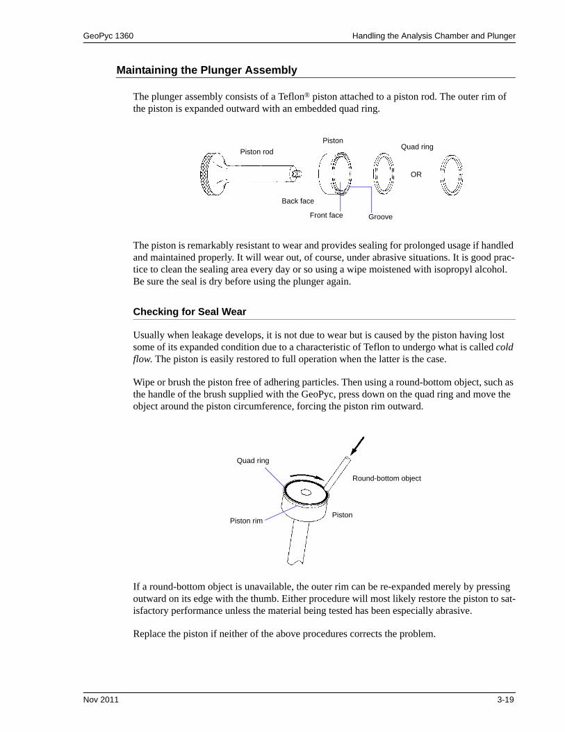
The plunger assembly consists of a Teflon® piston attached to a piston rod. The outer rim of the piston is expanded outward with an embedded quad ring.
The piston is remarkably resistant to wear and provides sealing for prolonged usage if handled and maintained properly. It will wear out, of course, under abrasive situations. It is good prac-tice to clean the sealing area every day or so using a wipe moistened with isopropyl alcohol. Be sure the seal is dry before using the plunger again.
Checking for Seal Wear
Usually when leakage develops, it is not due to wear but is caused by the piston having lost some of its expanded condition due to a characteristic of Teflon to undergo what is called cold flow. The piston is easily restored to full operation when the latter is the case.
Wipe or brush the piston free of adhering particles. Then using a round-bottom object, such as the handle of the brush supplied with the GeoPyc, press down on the quad ring and move the object around the piston circumference, forcing the piston rim outward.
If a round-bottom object is unavailable, the outer rim can be re-expanded merely by pressing outward on its edge with the thumb. Either procedure will most likely restore the piston to sat-isfactory performance unless the material being tested has been especially abrasive.
Replace the piston if neither of the above procedures corrects the problem.
Piston rod
PistonQuad ring
Back face
Front face Groove
OR
Quad ring
Piston rimPiston
Round-bottom object
Nov 2011 3-19

Handling the Analysis Chamber and Plunger GeoPyc 1360
Replacing the Plunger Piston
We recommend that you replace both the piston and the quad ring at the same time. Use the following instructions to replace the parts that are worn.
1. Unscrew the piston rod from the piston.
2. The quad ring is pre-loaded in the groove on the front of the piston. If it has become dislodged, insert the quad ring into the groove on the front face of the piston.
3. Screw the piston rod into the back face.
4. Tighten the plunger assembly firmly, but without using excessive force.
5. Test the tightness of the piston:
a. Place the plunger in an empty chamber.
b. Holding the plunger still, rotate the chamber around the plunger in a direction that would tend to unscrew the piston. If the motion of the chamber begins to unscrew the plunger assembly, it needs to be tightened further.
Refer to Ordering Information beginning on page 6-1 for part numbers and ordering infor-mation.
3-20 Nov 2011

GeoPyc 1360 Consolidation Force
Consolidation Force
The force with which the chamber contents are compressed is called the consolidation force. You specify the force you wish to use during the blank run.
The following table gives a typical force for each chamber.
Table 3-4. Typical Consolidation Force
Under certain circumstances, you may wish to use a different force. For example:
• You may wish to decrease the force when analyzing a very soft or fragile sample.
• If you enter too low a force, the plunger may move forward slowly or not at all. (If this occurs, start again using a greater force.)
• You should increase the force when performing an analysis with a sample plus DryFlo bed longer than the chamber’s diameter.
• If you find that the DryFlo remains compacted into cakes or clumps after analysis, you may be using too high a force.
As you develop your own methodology for operating the GeoPyc, you may wish to experi-ment with the consolidation force to find the value that works best for you.
The same force must be used for blank, sample, and calibration runs for a given sample.
Chamber Diameter (internal)
(mm)
Typical Consolidation Force
(N)
12.7 28
19.1 38
25.4 51
38.1 90
50.8 145
Nov 2011 3-21

Weighing Samples GeoPyc 1360
Weighing Samples
Before beginning a sample run with the GeoPyc, you must obtain the sample’s dry weight. Most sample materials gain weight by adsorbing moisture from the atmosphere. Care should be taken to ensure that the sample weight you enter does not include such moisture. (In some instances, you may wish to prepare the sample in a drying oven or dessicator.)
It does not matter, however, if the sample adsorbs moisture after it is weighed, since the GeoPyc measures sample volume. This means you can increase efficiency by drying and weighing a number of samples at once, then setting them aside until it is convenient for you to determine their envelope density.
3-22 Nov 2011

GeoPyc 1360 Definitions of Run Types
4. PERFORMING ANALYSES
This chapter contains instructions for determining the zero depth of a sample chamber, cali-brating the instrument, performing analyses, and storing blank data.
Definitions of Run Types
The GeoPyc performs four types of analyses:
• Sample• Store Blank• Calibration• Zero Depth
This section contains instructions for performing each of these run types. To obtain reproduc-ible analysis results, the runs should be performed in the following sequence.
1. Perform a zero depth run.
A zero depth run determines the distance the plunger moves into an empty sample chamber. The zero depth value is used to calculate the percent of sample in the sample bed. To obtain reproducible analysis results, at least 25% of the bed volume should be actual sample.
2. Perform a calibration run.
A calibration run is a series of consolidation cycles performed on DryFlo plus a reference object of known properties that is similar to the sample in size, shape, and quantity. The calibration run calculates a new conversion factor (refer to The Conversion Factor, page 4-4) to account for the irregularities of the sample.
3. Perform a blank data run.
A blank run measures the volume of DryFlo in the chamber. It is a series of consolidation cycles performed on the DryFlo alone.
A blank data run may be performed during a sample or calibration run. Alternatively, you may store blank data in advance, but this method may be less accurate.
4. Perform a sample run.
A sample run is a series of consolidation cycles performed on DryFlo plus the sample. It measures the volume of DryFlo plus sample. The sample run volume is compared to the blank volume (for the same quantity of DryFlo) to determine the envelope volume of the sample. Density and porosity data are calculated using this volume and other parameters provided during the sample run.
Jun 97 4-1

Determining the Zero Depth of a Sample Chamber GeoPyc 1360
Determining the Zero Depth of a Sample Chamber
The Percent Sample Volume
Sample quantity plays a significant role in reproducibility. A specimen extracted from a larger quantity of material must be of sufficient quantity to be representative of the whole. The spec-imen used determines the minimum sample chamber size required for analysis. A sample chamber should be selected in which the sample will constitute approximately 25% of the sample bed (sample plus DryFlo).
When you select the zero depth run from the Analyze menu, the zero depth of the sample chamber is determined and recorded. The GeoPyc uses this value to calculate automatically the percent of sample volume when you perform a sample run.
The sample volume percent is included in the Envelope Density Report. View this report to ensure that the sample bed contains an adequate amount of sample to produce valid results.
Zero Depth Sets
The GeoPyc will store up to five sets of zero depth data. When you perform a sample run, the GeoPyc will prompt you to enter the number of the zero depth data set you wish to use.
Performing a Zero Depth Run
A zero depth run is performed with an empty sample chamber. Do not place DryFlo or sample in the chamber for this type of run.
See Chapter 3 for instructions on general operation.
1. Attach the piston coupling extender to the piston rod.
2. Insert the plunger into the sample chamber and mount the chamber/ plunger assembly on the analyzer.
3. Make sure the ON/OFF switch on the rear panel is in the ON ( | ) position.
4. Press 2nd, then ANALYZE.
5. Enter the data as prompted.
Choose Zero Depth.Analyze type? Analyze
Zero Depth
4-2 Jun 97

GeoPyc 1360 Determining the Zero Depth of a Sample Chamber
6. Remove the chamber/plunger assembly from the GeoPyc.
7. Remove the extender from the piston rod.
Output Options
To print or transmit the Zero Depth Report, press the 2nd key, then PRINT or TRANSMIT. Select Zero Depth, then press ENTER. Refer to Zero Depth Report, page 5-10 for additional information and an example report.
Use the left and right arrow keys to choose the zero depth set you wish to use.
Range: 1 - 5
Enter the sample chamber diameter. If you do not know the sample chamber diameter, refer to Determining Your Chamber’s Diameter, page 3-14.
Range: 0 - 65.0000 mm
This number is printed on the report to indicate what size sample chamber was used; it is not used for calucations.
Press ENTER to begin the zero depth analysis. When the analysis is finished, the zero depth of the chamber is displayed.
Which Zero Depth set? Analyze
Zero Depth Set 1
Chamber diameter? Analyze
1.00000 mm
Press [Enter] to save changes,
or [Esc] to cancel.
Jun 97 4-3
Performing a Calibration Run GeoPyc 1360
Performing a Calibration Run
The Conversion Factor
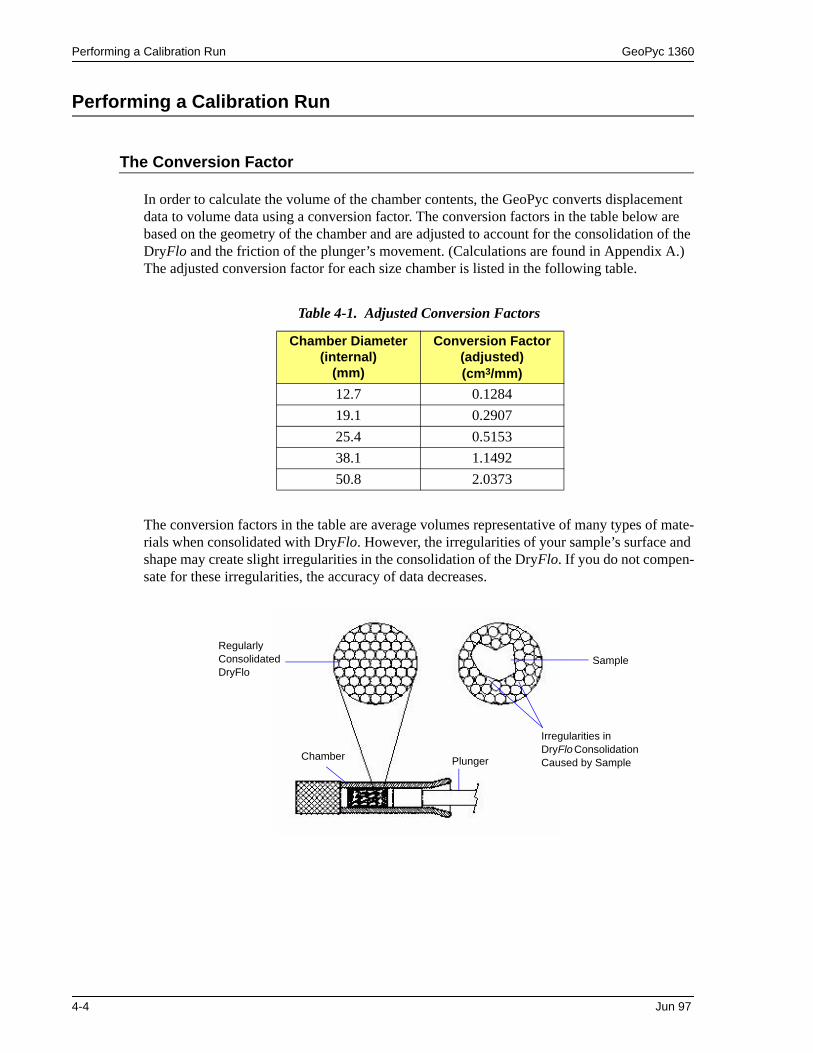
In order to calculate the volume of the chamber contents, the GeoPyc converts displacement data to volume data using a conversion factor. The conversion factors in the table below are based on the geometry of the chamber and are adjusted to account for the consolidation of the DryFlo and the friction of the plunger’s movement. (Calculations are found in Appendix A.) The adjusted conversion factor for each size chamber is listed in the following table.
Table 4-1. Adjusted Conversion Factors
The conversion factors in the table are average volumes representative of many types of mate-rials when consolidated with DryFlo. However, the irregularities of your sample’s surface and shape may create slight irregularities in the consolidation of the DryFlo. If you do not compen-sate for these irregularities, the accuracy of data decreases.
Chamber Diameter (internal)
(mm)
Conversion Factor (adjusted)(cm3/mm)
12.7 0.1284
19.1 0.2907
25.4 0.5153
38.1 1.1492
50.8 2.0373
Sample
Regularly Consolidated DryFlo
Irregularities in DryFlo Consolidation Caused by Sample
Chamber Plunger
4-4 Jun 97
GeoPyc 1360 Performing a Calibration Run
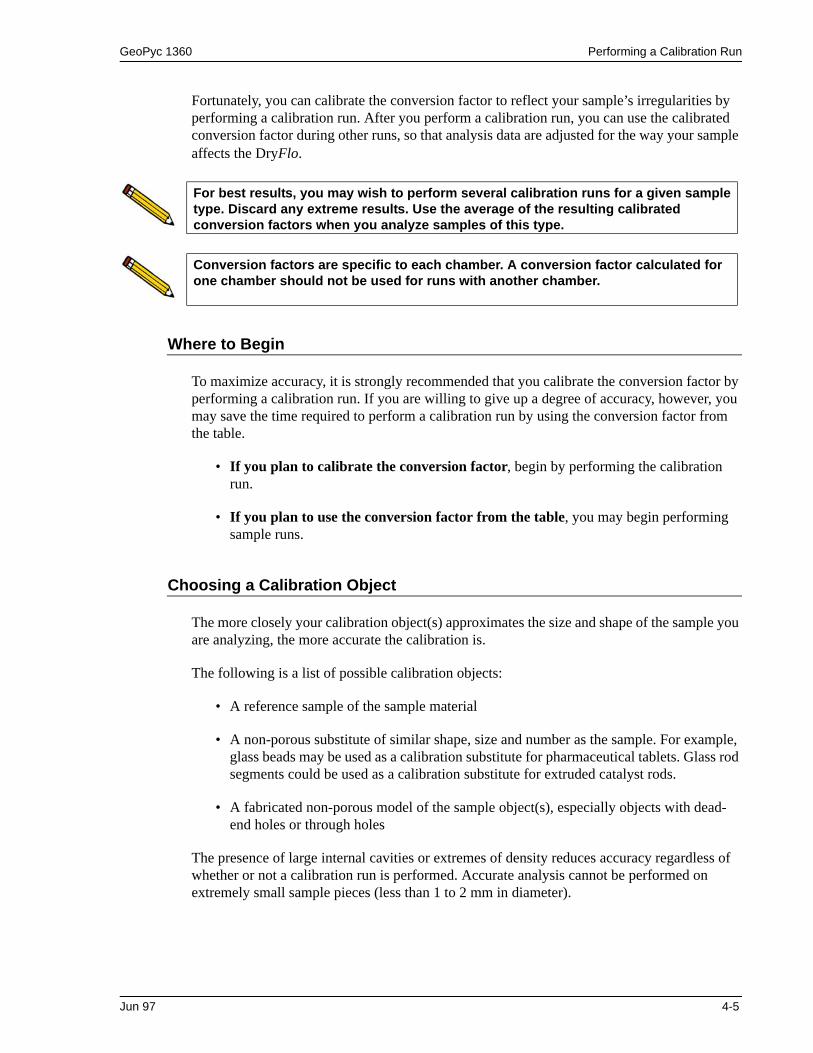
Fortunately, you can calibrate the conversion factor to reflect your sample’s irregularities by performing a calibration run. After you perform a calibration run, you can use the calibrated conversion factor during other runs, so that analysis data are adjusted for the way your sample affects the DryFlo.
Where to Begin
To maximize accuracy, it is strongly recommended that you calibrate the conversion factor by performing a calibration run. If you are willing to give up a degree of accuracy, however, you may save the time required to perform a calibration run by using the conversion factor from the table.
• If you plan to calibrate the conversion factor, begin by performing the calibration run.
• If you plan to use the conversion factor from the table, you may begin performing sample runs.
Choosing a Calibration Object
The more closely your calibration object(s) approximates the size and shape of the sample you are analyzing, the more accurate the calibration is.
The following is a list of possible calibration objects:
• A reference sample of the sample material
• A non-porous substitute of similar shape, size and number as the sample. For example, glass beads may be used as a calibration substitute for pharmaceutical tablets. Glass rod segments could be used as a calibration substitute for extruded catalyst rods.
• A fabricated non-porous model of the sample object(s), especially objects with dead-end holes or through holes
The presence of large internal cavities or extremes of density reduces accuracy regardless of whether or not a calibration run is performed. Accurate analysis cannot be performed on extremely small sample pieces (less than 1 to 2 mm in diameter).
For best results, you may wish to perform several calibration runs for a given sample type. Discard any extreme results. Use the average of the resulting calibrated conversion factors when you analyze samples of this type.
Conversion factors are specific to each chamber. A conversion factor calculated for one chamber should not be used for runs with another chamber.
Jun 97 4-5

Performing a Calibration Run GeoPyc 1360
Starting a Calibration Run
See Chapter 3 for general operating instructions.
1. Place an appropriate amount of DryFlo in the sample chamber. Do not place the calibration object in the chamber until you are prompted to do so.
2. Insert the plunger into the sample chamber, and push part way in. Wipe both ends of the chamber/plunger free of DryFlo and debris. Mount the chamber/plunger assembly on the analyzer.
3. Make sure that the ON/OFF switch on the rear panel is in the ON ( | ) position.
4. Press 2nd, then ANALYZE.
5. Enter the data as prompted.
If you set your system options setup (Chapter 3) to omit optional data fields, the corresponding prompts shown below will not appear when you operate the instrument.
Choose Calibration.
Enter an identification for this calibration object.
Enter the customer identification.
Enter your name.
Select Run blank now; the GeoPyc prompts you to perform the blank portion of this sample run. To use stored blank data, refer to Storing Blank Data, page 4-14.
Analyze type? Analyze
Calibration
Sample: Analyze
Sample 1
Customer: Analyze
Operator: Analyze
Blank data source? Analyze
Run blank now
4-6 Jun 97

GeoPyc 1360 Performing a Calibration Run
Enter the number of cycles (consolidation cycles) you wish the GeoPyc to perform during this blank run and calibration run.
To not include preparation cycles. The number of cycles you enter here is the number whose data will be used in calculations and reports.
Range: 1 - 20
Enter the Consolidation Force. A typical consolidation force for each size chamber is listed in Table 3-4. Typical Consolidation Force, page 3-21.
Range: 1 - 180 Newtons
The conversion factor is not used during the calibration run; accept the default.
Choose whether you wish to input the volume of the calibration object(s).
Choices: Yes, No
If Yes, enter the object’s volume:
Range: 0.0000 to 99.9999 cm3
If No, enter the following:
Range: 0 to 99.9999 g/cm3
Number of cycles: Analyze
Consolidation Force: Analyze
0.00000 Newtons
Conversion Factor: Analyze
1.00000 cm3/mm
Input Calibration Volume? Analyze
No
Calibration Volume: Analyze
0.0000 cm3
Absolute Density: Analyze
0.0000 g/cm3
Jun 97 4-7

Performing a Calibration Run GeoPyc 1360
6. The GeoPyc partially withdraws the plunger. Remove the chamber/plunger assembly from the analyzer. Carefully remove the plunger. Gently tap it on the open chamber so any adhering DryFlo falls back into the chamber. Brush back into the chamber any DryFlo clinging to the chamber’s edge. Set the plunger aside, seal end facing up. Slide the calibration object(s) gently down the side of the chamber.
It is assumed in calculations that the amount of DryFlo in the chamber for this calibration run is exactly the same as for the blank run you just performed. It is essential that you avoid losing DryFlo while placing the calibration object(s) in the chamber. If DryFlo is lost, you must cancel the run (press ESCAPE) and begin again.
7. Remount the chamber/plunger assembly on the analyzer, then press ENTER to begin calibration.
8. When the appropriate number of consolidation cycles is finished, the GeoPyc sounds an audible signal and partially withdraws the plunger.
9. Remove the chamber/plunger assembly from the analyzer and recover the calibration object(s).
When calibration is complete, the new (calibrated) conversion factor is displayed or printed. If you do not plan to print the calibration report, record the calibrated conversion factor so you can enter it during subsequent analyses. To clear the LCD screen and return to idle mode, press ESCAPE or ENTER.
You may now use the new conversion factor during sample runs that analyze objects similar to this calibration object.
(continued)
If No, enter the following:
Range: 0 to 99.9999 %
Range: 0 to 999.9999 g
Press ENTER to begin the blank portion of the calibration run. When analysis is finished, an audible signal is sounded.
Input Calibration Volume? Analyze
No
Porosity: Analyze
0.0000
Sample weight: Analyze
0.0000 g
Press [Enter] to save changes,
or [Esc] to cancel.
Data from this calibration run are replaced during the next analysis performed with the instrument. If you wish to print the calibration report or record the conversion factor, you must do so before performing another operation.
4-8 Jun 97

GeoPyc 1360 Performing a Calibration Run
Output Options
If you set your System Options to print or transmit reports automatically, the Calibration Report will be generated.
Press the 2nd key, then PRINT or TRANSMIT to generate additional copies or partial reports during analysis. (To do so, your system must be set up to print or transmit reports and con-nected to the appropriate output device.)
Refer to Calibration Report, page 5-6 for additional information and an example report.
Jun 97 4-9

Performing a Sample Run GeoPyc 1360
Performing a Sample Run
Refer to Chapter 3 for instructions on general operation.
1. Place an appropriate amount of DryFlo in the sample chamber. Do not place the sample object in the chamber until you are prompted to do so.
2. Insert the plunger into the sample chamber, and push part way in. Wipe both ends of the chamber/plunger free of medium and debris. Mount the chamber/plunger assembly on the analyzer.
3. Make sure that the ON/OFF switch on the rear panel is in the ON ( | ) position.
4. Press 2nd, then ANALYZE.
5. Enter the data as prompted. If you set your system options setup (Chapter 3) to omit an optional data field, the corresponding prompt shown below will not appear when you operate the instrument.
For greatest accuracy, perform a calibration run before analyzing samples.
Choose Sample.
Enter the sample identification.
Range: 19 characters
Enter the customer identification.
Range: 9 characters
Enter your name.
Range: 9 characters
For consistent results and correlation with other parameters, enter the dry sample weight.
Range: 0.0000 to 99.9999 grams
Analyze type? Analyze
Sample
Sample: Analyze
Sample 1
Customer: Analyze
Operator: Analyze
Sample weight: Analyze
0.0000 g
4-10 Jun 97

GeoPyc 1360 Performing a Sample Run
(optional) For the GeoPyc 1360 to calculate percentage porosity and specific pore volume, you must supply sample absolute density.
Range: 0.0000 to 99.9999 g/cm3
Displays when Yes is selected for Calculate % Sample Volume in System Options.
Range: 1 - 5
Choose the method for blank data.
Choices: Run blank now Stored blank data set [n]
Run blank now; the GeoPyc prompts you to perform the blank portion of this sample run.
Stored blank data: enter the data set number you wish to use with this analysis. Refer to Storing Blank Data, page 4-14.
Displays when No is selected for Calculate % Sample Volume in System Options.
Enter the sample chamber diameter. If you do not know the diameter, see Determining Your Chamber’s Diameter, page 3-14.
Range: 0 - 65.0000 mm
This number is printed on the report to indicate what size sample chamber was used; it is not used for calculations.
Enter the number of cycles (consolidation cycles) you wish performed during this blank run and sample run.
Do not include preparation cycles. The number of cycles you enter here is the number whose data will be used in calculations and reports.
Range: 1 - 20
Absolute density: Analyze
0.0000 g/cm3
Which Zero Depth set? Analyze
Zero Depth Set 1
Blank Data Source? Analyze
Run blank now
Chamber Diameter: Analyze
1.0000
Number of cycles: Analyze
Jun 97 4-11

Performing a Sample Run GeoPyc 1360
Enter the Consolidation Force. A typical consolidation force for each size chamber is listed in Table 3-4. Typical Consolidation Force, page 3-21.
Range: 1 - 180 Newtons
Enter the conversion factor. After the first run (of any type) performed with this instrument, the conversion factor is defaulted to the last conversion factor used. You may accept the default or enter a new conversion factor.
To maximize accuracy, use a conversion factor that was calibrated (during a calibration run) for this type of sample and this chamber. If an appropriate calibrated conversion factor is not available, use the conversion factor from Table 4-1, page 4-4. Factors used from this table may yield less accurate data as compared to a calibrated conversion factor.
Range: 0 to 9.9999 cm3/mm
Displays when you are using a stored blank data set.
Enter either the weight of the chamber plus medium, or the weight of the medium only. Including or excluding the chamber’s weight makes no difference in analysis calculations, but you must use the same method for both the blank and sample runs for a given sample.
Range: 000.0000 to 999.9999 grams
Consolidation Force: Analyze
0.00000 Newtons
Conversion Factor: Analyze
1.0000 cm3/mm
Chamber/Medium weight: Analyze
0.0000 cm3/mm
Entering an extremely accurate weight is critical.
Press ENTER to begin the blank portion of the sample run. When analysis is finished, an audible signal is sounded.
Press [Enter] to save changes,
or [Esc] to cancel.
4-12 Jun 97
GeoPyc 1360 Performing a Sample Run
6. The GeoPyc 1360 partially withdraws the plunger. Unscrew the plunger from the right mandrel, push the plunger part way into the chamber, then unscrew the sample chamber from its mandrel.
Carefully remove the plunger. Gently tap it on the open chamber so any adhering DryFlo falls back into the chamber. Brush back into the chamber any DryFlo clinging to the flared edge. Set the plunger aside, seal end facing up. Slide the sample object(s) gently down the side of the chamber.
It is assumed in calculations that the amount of DryFlo in the chamber for this sample run is exactly the same as for the blank run you just performed. It is essential that you avoid losing DryFlo while placing the sample object(s) in the chamber. If DryFlo is lost, you must cancel the run (press ESCAPE) and begin again.
7. Replace the chamber/plunger on the analyzer. Press ENTER, and analysis automatically begins.
8. When the appropriate number of consolidation cycles is finished, an audible signal is sounded, and the plunger partially withdraws from the chamber. Remove the chamber/plunger, then recover the sample.
Analysis data are displayed on the LCD screen. To clear the screen and return to idle mode, press ESCAPE or ENTER.
Output Options
If you set your System Options to print or transmit reports automatically, the Envelope Density Report will be generated now.
Press the 2nd key, then PRINT or TRANSMIT to generate additional copies after analysis or partial reports during analysis. (To do so, your system must be set up to print or transmit reports and connected to the appropriate output device.)
Refer to Reports, page 5-4 for additional information and example reports.
Jun 97 4-13

Storing Blank Data GeoPyc 1360
Storing Blank Data
See Chapter 3 for instructions on general operation.
See the preceding sections for definitions of blank, sample, and calibration runs.
Although maximum accuracy is achieved when a blank run is performed immediately before each sample run, it is possible to save time by using stored blank data.
Blank data are stored in sets. A group of stored blank runs using the same consolidation force and number of preparation cycles is called a Stored Blank Data Set.
The GeoPyc 1360 can store 10 blank data sets. For each set, you may include data from up to 10 blank runs using graduated quantities of DryFlo. Each set must contain data for at least two quantities of DryFlo. The GeoPyc is then able to interpolate blank volumes between the data points in the set; the appropriate interpolated blank run data are used when you perform your sample run.
How Stored Blank Data are Used
Follow the instructions in this chapter for performing a sample or calibration run. For blank data source, indicate which stored data set to use.
• You specify the number of consolidation cycles for the current run. The GeoPyc uses that number of stored blank run cycles, even if more were stored in the set.
• The number of preparation cycles, consolidation force and conversion factor from the stored data set are used for the current run. You may change the default conversion factor to the calibrated conversion factor for the type of sample you are analyzing.
• You are prompted to enter the Chamber/Medium weight; the GeoPyc interpolates the corresponding stored blank data from that set. Entering an extremely accurate weight is critical.
This method requires extremely careful weighing of DryFlo and sometimes yields less accurate data.
4-14 Jun 97

GeoPyc 1360 Storing Blank Data
Example of How Stored Blank Data are Used
Below is an example of some of the data stored in a blank data set. If Chamber/Medium weight Y were entered during a sample run using this data set, analysis data would be interpo-lated between points 2 and 3 (shaded). The number of cycles specified in the sample run in this example is 7.
XXXXX represents analysis data in counts.
Sample Run Parameters:Chamber/Medium Weight: Y gCycles: 7
The number of cycles specified in the sample run determines the number of blank cycles used in calculations.
When you enter the Chamber/Medium weight for your sample run, the GeoPyc determines which two stored blank Chamber/Medium weights it falls between. Each of these weights was measured for a specific number of cycles. You cannot specify more cycles for the sample run than the smaller of these two numbers.
Numberof Cycles
Stored Chamber; Medium
Wt 1X1 g
Stored Chamber; Medium
Wt 2X2 g
Stored Chamber; Medium
Wt 3X3 g
Stored Chamber; Medium
Wt 4X4 g
Stored Chamber; Medium
Wt 5X5 g
< Y Y g > Y
1 XXXXX XXXXX XXXXX XXXXX XXXXX
2 XXXXX XXXXX XXXXX XXXXX XXXXX
3 XXXXX XXXXX XXXXX XXXXX XXXXX
4 XXXXX XXXXX XXXXX XXXXX XXXXX
5 XXXXX XXXXX XXXXX XXXXX XXXXX
6 XXXXX XXXXX XXXXX XXXXX XXXXX
7 XXXXX XXXXX XXXXX
8 XXXXX XXXXX
9 XXXXX XXXXX
10 XXXXX
11 XXXXX
12 XXXXX
13 XXXXX
14 XXXXX
15 XXXXX
Jun 97 4-15

Storing Blank Data GeoPyc 1360
In the example above, the Chamber/Medium weight from the sample run (Y) falls between stored weights 2 and 3. Weight 2 was measured for 15 cycles, but weight 3 was measured for only 9 cycles. Data can, therefore, only be interpolated for 9 points, so 9 is the maximum num-ber of cycles for which the sample can be analyzed.
To determine the maximum number of cycles you may specify, it may be helpful to look at a Blank Data Set Listing.
Weighing the DryFlo
When you are storing blank data, you must enter the quantity of DryFlo, used in each run. This quantity is called the Chamber/Medium weight. (This step is not necessary when you per-form a single blank run embedded in a sample or calibration run.)
We recommend weighing DryFlo in the analysis chamber. This reduces the possibility of error in transferring DryFlo from a weighing container to the chamber.
If it is necessary to transfer the DryFlo from a weighing container to the chamber, be careful not to lose any DryFlo in the process. Avoid splashing, and brush into the chamber any DryFlo clinging to the weighing container or to the flared end of the chamber. Even a small amount of DryFlo residue remaining in the measuring container will affect analysis results.
When the GeoPyc prompts you to enter the Chamber/Medium weight, you may enter either the weight of the chamber plus DryFlo or the weight of the DryFlo only. Including or exclud-ing the chamber’s weight makes no difference in analysis calculations, but you must use the same method for both the blank and sample runs for a given sample. If, for example, you include the chamber’s weight in your blank run, then you must include the chamber’s weight in your sample run.
Accurately weighing the DryFlo is critical for obtaining acceptable results using stored blank data. A precision analytical balance accurate to 1 mg is required. If you cannot achieve this level of accuracy, you may find the technique of using stored blank data less than satisfactory.
4-16 Jun 97

GeoPyc 1360 Storing Blank Data
To Begin Storing Data
To store blank run data, begin with an amount of DryFlo slightly smaller than the smallest amount you plan to use during analysis. Perform the blank run, add a small quantity of DryFlo, then repeat until the chamber contains slightly more than the largest amount of DryFlo you will use. You can print a report of your stored blank data at any time.
Use the following instructions to start storing data in a new set or to add data to an existing set.
1. Carefully place a quantity of DryFlo in the sample chamber, and weigh it. Accurate weighing is critical.
2. Insert the plunger into the sample chamber, and push part way in. Mount the chamber/plunger assembly on the analyzer.
3. Make sure that the ON/OFF switch on the rear panel is in the ON ( | ) position.
4. Press 2nd, then ANALYZE.
5. Enter the data as prompted.
Choose Store blank data.
Use the left and right arrow keys to choose the blank data set you wish to use.
Range: 1 - 10
Enter an identification for the blank data set.
Range: 9 characters
Enter the number of cycles (consolidation cycles) you wish the GeoPyc 1360 to perform during this blank run.
Do not include preparation cycles.
Range: 1 - 20
Analyze type? Analyze
Store blank data
Blank data source? Analyze
Stored blank data set 1
Blank Data Set: Analyze
Number of cycles: Analyze
Jun 97 4-17

Storing Blank Data GeoPyc 1360
6. The GeoPyc partially withdraws the plunger. Unscrew the plunger from the right mandrel, push the plunger part way into the chamber, then unscrew the sample chamber from its mandrel. The following prompt is displayed.
If you wish to continue storing blank run data in this set, change the amount of DryFlo and repeat the process, beginning with chamber/medium weight.
Enter the Consolidation Force. A typical consolidation force for each size chamber is listed in Table 3-4. Typical Consolidation Force, page 3-21.
Range: 1 - 180 Newtons
Consolidation Force: Analyze
0.00000 Newtons
The consolidation force must have the same value for every run in a Stored Blank Data Set. The value you enter when you start the first run in a Stored Blank Data Set will automatically appear in subsequent runs. If you attempt to change it, you are warned that this will erase all blank data stored for this set.
Enter the conversion factor. After the first run (of any type) performed with this instrument, the conversion factor is defaulted to the last conversion factor used.
Range: 0 to 9.9999 cm3/mm
Enter either the weight of the chamber plus medium, or the weight of the medium only. Including or excluding the chamber’s weight makes no difference in analysis calculations, but you must use the same method for both the blank and sample runs for a given sample.
Range: 000.0000 to 999.9999 grams
Conversion Factor: Analyze
1.0000 cm3/mm
Chamber/Medium weight: Analyze
0.0000 cm3/mm
Entering an extremely accurate weight is critical.
Press ENTER to begin the blank analysis. When analysis is finished, an audible signal is sounded.
Press [Enter] to save changes,
or [Esc] to cancel.
Change amount of medium, press [Enter] for another blank, or [Esc] to end.
4-18 Jun 97
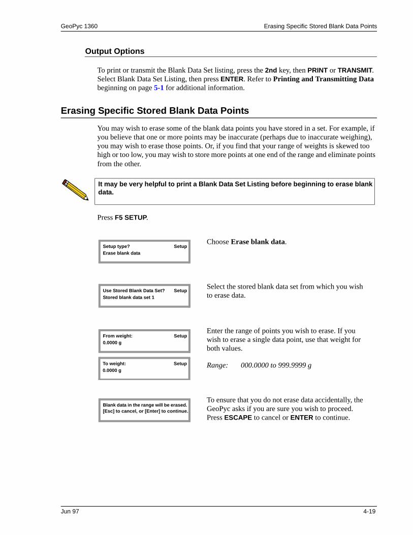
GeoPyc 1360 Erasing Specific Stored Blank Data Points
Output Options
To print or transmit the Blank Data Set listing, press the 2nd key, then PRINT or TRANSMIT. Select Blank Data Set Listing, then press ENTER. Refer to Printing and Transmitting Data beginning on page 5-1 for additional information.
Erasing Specific Stored Blank Data Points
You may wish to erase some of the blank data points you have stored in a set. For example, if you believe that one or more points may be inaccurate (perhaps due to inaccurate weighing), you may wish to erase those points. Or, if you find that your range of weights is skewed too high or too low, you may wish to store more points at one end of the range and eliminate points from the other.
Press F5 SETUP.
It may be very helpful to print a Blank Data Set Listing before beginning to erase blank data.
Choose Erase blank data.
Select the stored blank data set from which you wish to erase data.
Enter the range of points you wish to erase. If you wish to erase a single data point, use that weight for both values.
Range: 000.0000 to 999.9999 g
To ensure that you do not erase data accidentally, the GeoPyc asks if you are sure you wish to proceed. Press ESCAPE to cancel or ENTER to continue.
Setup type? Setup
Erase blank data
Use Stored Blank Data Set? Setup
Stored blank data set 1
From weight: Setup
0.0000 g
To weight: Setup
0.0000 g
Blank data in the range will be erased. [Esc] to cancel, or [Enter] to continue..
Jun 97 4-19

Tips for Successful Operation GeoPyc 1360
Tips for Successful Operation
The following is a list of tips for operating the GeoPyc:
• Performing a calibration run using an object or objects similar to the sample in size and shape calibrates the conversion factor used during analysis; a calibrated conversion factor yields more accurate results than the calculated conversion factor.
• The closer the calibration object simulates the sample in size, shape, and quantity, the better the calibration will be. Calibration with a reference standard works best of all.
• Unless time is critical, performing an embedded blank run during each sample run (the Run Blank Now option) is preferable to using stored blank data.
• DryFlo bed lengths no longer than the diameter of the chamber are recommended unless sample shape demands otherwise.
• If final bed length must exceed the diameter of the chamber, you should increase the consolidation force. An increase in force proportional to the increase in bed length is recommended.
• A single-object sample should be run in the smallest chamber in which it will fit, allowing for consolidated DryFlo on all sides.
• Large sample quantities (of multi-piece samples) are more representative than small quantities, so analyzing a larger quantity of sample in a large chamber may yield more accurate results than analyzing a small quantity of sample in a small chamber.
• The sample must constitute at least 25% of the final bed volume. The GeoPyc will calculate the percent of sample volume automatically when you:
–Select Yes at the Calculate % sample volume prompt in Systems Options.
–Use a zero depth set from a zero depth run that was performed using the same sample chamber to be used for the sample run.
4-20 Jun 97

GeoPyc 1360 Verifying Operation
Verifying Operation
When installing an instrument or if you obtain analysis results that are unexpected or unusual, you should verify the operation of your GeoPyc.
1. Perform a calibration run as described earlier in this chapter.
2. Perform an analysis without a sample. Follow the directions for performing a sample run (refer to Performing a Sample Run, page 4-10). Enter zero for sample weight and density, or enter zero volume for the sample. When you are prompted to place the sample in the chamber, remove the chamber/plunger assembly from the analyzer, but DO NOT remove the plunger. Shake the chamber/plunger assembly to eliminate any compaction of the DryFlo, then replace it on the analyzer. The reported envelope volume for the sample should be very nearly zero if the instrument is performing correctly.
3. Perform a sample run using the same object(s) used in the calibration run. During the sample run, be sure to use the calibrated conversion factor resulting from the calibration run. The sample run results should be within a percent or so of the values ascribed to the sample material during the calibration run.
If the procedures above reveal analysis errors:
1. Make sure your DryFlo is flowing freely and not contaminated. Changing to fresh DryFlo is recommended.
2. Evaluate the accuracy of your technique. Are you losing DryFlo due to splashing or spilling when the sample/calibration object is introduced into the chamber? If you are using stored blank data, are you using an extremely accurate method for weighing the DryFlo? (Weights must be accurate to within a few milligrams.)
3. Evaluate the accuracy of your balance using manufacturer’s instructions.
4. Consider whether the chamber/plunger assembly may have become loosened from the analyzer during analysis. If you do not attach the chamber and plunger to each mandrel securely, data may be inaccurate.
5. Calibrate the force transducer (refer to Appendix C).
You can also check correct interpolation within stored blank data using this method. Be sure to use a quantity of DryFlo within the range stored in the set. If the resulting volume is not close to zero, the first possible cause to evaluate is your weighing accuracy and repeatability. Unless precise weights are obtained, the stored blank test procedure can give misleading results.
Jun 97 4-21

Reviewing and Editing Analysis Parameters GeoPyc 1360
Reviewing and Editing Analysis Parameters
See Chapter 3 for instructions on general operation.
After an analysis, you can use the Review function to change some of the variables used for calculations and reporting. (Of course, variables that control the conditions of the analysis, such as consolidation force, cannot be changed once the analysis has been performed.) For example, after reviewing the Envelope Density Report generated for a given sample, you may wish to change the conversion factor, then print another report.
Press F6 REVIEW; the following information is displayed:
Sample:Customer:Operator:Sample weight:Absolute density:Blank Data Set:Conversion factor:Calibration volume:
Use the (Up) and (Down) arrows to move through these fields to check them, making any necessary changes.
Press ESCAPE at any time to abandon changes. Press 2nd, then SAVE at any time to save changes. Also, after you check or change the calibration volume, the following prompt is displayed:
After you save the changes, you can generate a report using the new values. See Chapter 5 for instructions on printing and transmitting data.
Press [Enter] to save changes,
or [Esc] to cancel.
Data from an analysis are retained only until the next analysis is performed. A review can only be performed on the last sample that was analyzed.
4-22 Jun 97

GeoPyc 1360 Viewing Analysis Results
Viewing Analysis Results
As an analysis is performed, operational status messages are displayed. When the analysis is complete, you may view data from the analysis on the GeoPyc display. Use the (Up) and (Down) arrows to move through the data. The last data items are the summary results. Use the (Left) and (Right) arrows to move through the summary results.
Canceling a Run
See Chapter 3 for instructions on general operation.
You can cancel a run at any time by pressing ESCAPE. To protect you from accidentally can-celing a run, the following prompt will be displayed:
Press [Enter] to save changes,
or [Esc] to cancel.
Jun 97 4-23


GeoPyc 1360 Printed Report
5. PRINTING AND TRANSMITTING DATA
You may export data to a printer or via RS-232 cable to a computer file. Complete the Report Options and/or Transmission Options setup dialogs (described in Chapter 3) to enable your system to print or transmit reports.
Analysis and calibration reports remain available for printing until another analysis or calibra-tion is performed. When you perform an analysis, reports from the previous analysis or calibration are deleted. A current report on stored blank data is available at any time.
Each optional output method is discussed below. This chapter also includes a sample and description of each type of printed report.
Printed Report
See Chapter 3 for instructions on general operation.
• Before you can print reports, you must complete the Report Options setup dialog (refer to Report Options, page 3-8).
• A report is automatically generated after completion of an analysis.
• A compatible printer must be attached to the analyzer in order to print reports.
• You can stop printing at any time by pressing ESCAPE.
To print additional reports after an analysis, or to print reports of partial data at any time during operation, press 2nd, then PRINT.
Choose whether you wish to print a standard report, a report on stored blank data, or a zero depth report.
Choices: Report, Blank Data Set Listing, Zero Depth
Report Print the standard report for the last analysis performed (the Envelope Density Report for a sample run, or the Calibration Report for a calibration run). Press ENTER; the report is printed.
Zero Depth Print a report on zero depth data. Press ENTER; a report including all stored zero depth sets is printed.
Print type? Print
Report
Jun 97 5-1

Printed Report GeoPyc 1360
Blank Data Set Listing Print a report on stored blank data. Press ENTER; the following prompt is displayed:
Select the stored blank data set for this report. Press ENTER; the stored blank data set is printed.
Blank data source? Print
Stored blank data set 1
5-2 JUn 97
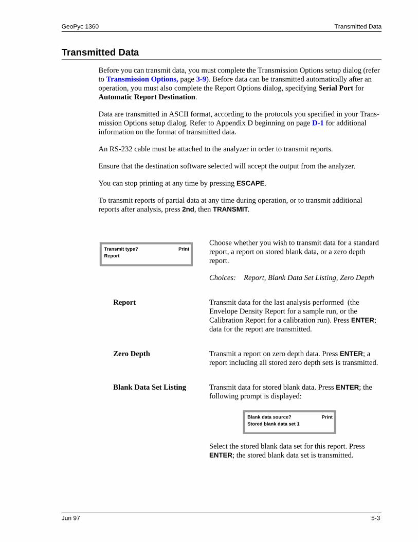
GeoPyc 1360 Transmitted Data
Transmitted Data
Before you can transmit data, you must complete the Transmission Options setup dialog (refer to Transmission Options, page 3-9). Before data can be transmitted automatically after an operation, you must also complete the Report Options dialog, specifying Serial Port for Automatic Report Destination.
Data are transmitted in ASCII format, according to the protocols you specified in your Trans-mission Options setup dialog. Refer to Appendix D beginning on page D-1 for additional information on the format of transmitted data.
An RS-232 cable must be attached to the analyzer in order to transmit reports.
Ensure that the destination software selected will accept the output from the analyzer.
You can stop printing at any time by pressing ESCAPE.
To transmit reports of partial data at any time during operation, or to transmit additional reports after analysis, press 2nd, then TRANSMIT.
Choose whether you wish to transmit data for a standard report, a report on stored blank data, or a zero depth report.
Choices: Report, Blank Data Set Listing, Zero Depth
Report Transmit data for the last analysis performed (the Envelope Density Report for a sample run, or the Calibration Report for a calibration run). Press ENTER; data for the report are transmitted.
Zero Depth Transmit a report on zero depth data. Press ENTER; a report including all stored zero depth sets is transmitted.
Blank Data Set Listing Transmit data for stored blank data. Press ENTER; the following prompt is displayed:
Select the stored blank data set for this report. Press ENTER; the stored blank data set is transmitted.
Transmit type? Print
Report
Blank data source? Print
Stored blank data set 1
Jun 97 5-3

Reports GeoPyc 1360
Reports
Blank Data Set Listing
You can print a Blank Data Set Listing for each set of data you have stored.
For each quantity of DryFlo stored in the set, this report lists the counts (steps moved by the displacement device) during each cycle.
The variables you specified when you stored the blank data (set number, conversion factor, number of preparation cycles, set identification, consolidation force) are listed at the top of the report. The instrument serial number, operator name, date, and time also are displayed.
How to use this report:
This report is very helpful when you wish to add or delete stored blank data because it enables you to evaluate the range of DryFlo weights you have stored. For example, after reviewing a Blank Data Set Listing, you may realize that all your DryFlo weights are too low, and that you should store additional data in the set using larger amounts of DryFlo.
In the case of deleting data, this report helps you identify the DryFlo weights you wish to delete.
When you are performing sample or calibration runs using stored data, looking at current Blank Data Set Listings enables you to select the appropriate set (if you have stored more than one set) and helps you make sure the amount of DryFlo you are using in the current run is within the range of DryFlo amounts you have stored in the set.
5-4 JUn 97

GeoPyc 1360 Reports
Example of Blank Data Set Listing Report
Jun 97 5-5

Reports GeoPyc 1360
Calibration Report
This report lists the counts (steps moved by the displacement device) during each cycle of a calibration run. A calibration run is performed using a calibration object of known properties similar to the sample in size, shape, and quantity. A complete discussion of calibration runs is contained in Chapter 4.
The variables specified for the calibration run are listed at the top of the report. The instrument serial number, operator name, date, and time also are displayed.
For each cycle, the report lists:
Below these data points, the report displays the average envelope volume and standard devia-tion, as well as the volume error (the adjustment to the volume attributed to the sample’s shape, size, etc.).
How to use this report:
At the bottom of the report, the conversion factor is printed. Use this conversion factor in sam-ple runs for samples similar to the calibration object used in this run. For even greater accuracy, perform three calibration runs and average the conversion factors from the three reports. Use the average as the conversion factor in sample runs for this type sample.
Blank counts: The number of steps the motor moved to achieve the consolidation force specified for the blank run.
Sample counts: The number of steps the motor moved to achieve the consolidation force specified for the sample run.
Volume: The difference between the blank and sample counts, converted by the GeoPyc to volume.
Deviation (volume): The difference between the average envelope volume and the volume measured for this consolidation cycle.
5-6 JUn 97
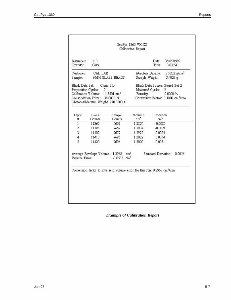
GeoPyc 1360 Reports
Example of Calibration Report
Jun 97 5-7

Reports GeoPyc 1360
Envelope Density Report
This report lists the counts (steps moved by the displacement device) during each cycle of a sample run.
The variables specified for the sample run are listed at the top of the report. The instrument serial number, operator name, date, and time also are displayed. For each cycle, the report lists:
Below these data points, the report displays average envelope volume and its standard devia-tion, and average envelope density and its standard deviation.
If you entered absolute density data, the report prints the percent porosity and specific pore volume. If you entered a zero depth set number, the percent sample volume is displayed.
How to use this report:
The data in this report can be used to make comparisons between samples and comparisons of samples against your standards or specifications. It can also be used to ensure that an adequate amount of sample was contained in the sample bed. To ensure reproducible results, at least 25% of the sample bed should be actual sample.
Blank counts: The number of steps the motor moved to achieve the consolidation force specified for the blank run.
Sample counts: The number of steps the motor moved to achieve the consolidation force specified for the sample run.
Volume: The difference between the blank and sample counts, converted by the GeoPyc to volume.
Deviation (volume): The difference between the average envelope volume and the volume measured for this consolidation cycle.
Density: The envelope density calculated for the sample during this consolidation cycle.
Deviation (density): The difference between the average density and the density for this cycle.
5-8 JUn 97

GeoPyc 1360 Reports
Example of Envelope Density Report
**If you select No at the Calculate % sample volume? prompt in System Options, these fields display as follows:
Zero Depth: not used Percent Sample volume: xx.xxx %
Jun 97 5-9

Reports GeoPyc 1360
Zero Depth Report
This report lists the chamber diameter and zero depth contained in up to five zero depth sets.
For each zero depth run, the report lists:
How to use this report:
This report shows the zero depth of up to five sample chambers. The zero depth is used to cal-culate the percent of sample in the sample bed. This percentage is shown in the Envelope Density Report.
Chamber diameter: The user-entered diameter of the chamber in millimeters.
Zero depth: The zero depth of the sample chamber, which is the depth to which the plunger travels when the sample chamber is empty.
5-10 JUn 97

GeoPyc 1360 Reports
Example of Zero Depth Report
Jun 97 5-11


GeoPyc 1360 Ordering Information
6. ORDERING INFORMATION
Part Number Item and Description
136-00000-00 GeoPyc 1360 Pycnometer for determining envelope volume and envelope density. When absolute density is provided, the GeoPyc also calculates pore volume and percent porosity. Includes internal computer with software, LCD screen, operator’s manual, and keypad.
004-16831-01 DryFlo, 3 L
136-42001-00 English language overlay (keypad template)
136-42002-00 Spanish language overlay (keypad template)
136-42003-00 French language overlay (keypad template)
136-42004-00 German language overlay (keypad template)
136-42005-00 Italian language overlay (keypad template)
136-25852-01 Piston coupling extender, for zero depth runs
136-25801-03 Plunger, for 12.7, 19.1, and 25.4-mm chamber
136-25804-03 Plunger, for 38.1 and 50.8-mm chamber
136-25801-00 Sample chamber and plunger assembly, 12.7-mm ID
136-25801-10 Sample chamber, 12.7-mm ID
136-25801-07 Piston, for 12.7-mm ID plunger
136-25802-00 Sample chamber and plunger assembly, 19.1-mm ID
136-25802-10 Sample chamber, 19.1-mm ID
136-25802-07 Piston, for 19.1-mm ID plunger
136-25803-00 Sample chamber and plunger assembly, 25.4-mm ID
136-25803-10 Sample chamber, 25.4-mm ID
136-25803-07 Piston, for 25.4-mm ID plunger
136-25804-00 Sample chamber and plunger assembly, 38.1-mm ID
136-25804-10 Sample chamber, 38.1-mm ID
136-25804-07 Piston, for 38.1-mm ID plunger
136-25805-00 Sample chamber and plunger (piston), 50.8-mm ID
136-25805-10 Sample chamber, 50.8-mm ID
136-25805-07 Piston, for 50.8-mm ID plunger
Nov 2011 6-1

Ordering Information GeoPyc 1360
Part Number Item and Description
004-32177-00 Funnel, plastic
004-27059-00 Sieve, No. 35, 500 m
004-27065-00 Sieve pan, 3-in. diameter
004-54613-00 Brush, dusting, 3/8-in. wide x 3/4-in. long
136-34800-00 Spring Standard (Force Transducer Calibration Fixture)
136-42801-00 Operator’s Manual
136-33005-00 T.A.P. density option. Includes software card, manual, piston coupling extension, and upgrade information.
130-00001-00 AccuPyc 1330 Helium Pycnometer, 1 cm3, for absolute density measurement
130-00000-00 AccuPyc 1330 Helium Pycnometer, 10 cm3, for absolute density measurement
133-00002-00 AccuPyc 1330 Helium Pycnometer, 100 cm3, for absolute density measurement
Call for model and part number.
Printer, connects to the GeoPyc 1360 or to the AccuPyc 1330 to print reports.
6-2 Nov 2011

GeoPyc 1360 Appendix A
A. CALCULATIONS
This appendix includes calculations for information presented on the envelope density report.
The envelope volume of a sample is determined by the difference in how far the plunger is driven (by a stepping motor) into a cylinder containing only DryFlo and then when sample is added. The steps of the motor (C) are counted and used to calculate volume; they are also shown on reports. The counts are converted to volume by multiplying them by the conversion factor (v, cm3/count). The conversion factor is displayed as cm3/mm.
The default envelope volume of the sample V is then the difference in the counts with the sample present Cpresent and with it absent Cabsent multiplied by v or
(1)
When a calibration test is made with a sample of known volume V, the above equation is solved for v. This value of v then becomes the conversion factor (conversion factors expressed as cm3/mm are similarly derived).
The envelope density of the sample e is its mass W divided by its envelope volume or
(2)
The porosity of a sample P as a percentage when its absolute density a is known is given by
(3)
The sample specific pore volume Vp is given by
(4)
When a calibration test is made with a sample of known weight W, absolute density a, and porosity P, eq. 3 with eq. 2 substituted for e is used to calculate envelope volume V as required of eq. 1.
V Cpresent Cabsent– v cm3=
eWV----- g/cm3=
P 1e
a
-----– 100 %=
Vp1e
----- 1a
-----– cm3/g=
Jun 96 A-1

Appendix A GeoPyc 1360
The percent sample volume (the percentage of the bed volume which is actual sample) is given by
(5)
where
Zero depth = the distance (mm) the plunger moves into an empty sample chamber until it contacts the bottom of the chamber
Step size = 25.4 mm/in. 9600 steps/in.
The following table lists the calculated conversion factor for each size chamber. It also lists adjusted conversion factors based on a multitude of tests assessing cylinder wall friction and other factors. The conversion factors listed here are intended primarily as a starting point for situations where it is not practical to calibrate the conversion factor. (Obtaining a calibrated conversion factor by performing a calibration run is the preferred method.)
It may be necessary to alter the adjusted conversion factor according to analysis variables, such as the consolidation force. If you wish to fine-tune the adjusted conversion factor, you must develop a methodology suited to the analysis parameters you select and the specifica-tions you must meet. Results using the adjusted conversion factors rarely will be outside the 3% error range.
Internal Chamber Diameter
(mm)
Calculated Conversion Factor
(cm3/mm)
Adjusted Conversion Factor
(cm3/mm)
12.7 0.1267 0.1284
19.1 0.2850 0.2907
25.4 0.5067 0.5153
38.1 1.1401 1.1492
50.8 2.0268 2.0373
VS
Average of Cabsent Average of Cpresent–
Zero depthStep size
-------------------------- Average of Cpresent–
-----------------------------------------------------------------------------------------------
100 %=
A-2 Jun 96

GeoPyc 1360 Appendix B
B. ERROR MESSAGES
This appendix includes the error messages you may encounter while operating the GeoPyc software. For your convenience, they are arranged in alphabetical order.
ANALYSIS_ERR: Divided by zero.Unable to calculate calib. volume.
ANALYSIS_ERR: Limit switch is on Failed to reach target force.
ANALYSIS_ERR: Unable to calculateblank data from the Blank Data Set.
Cause: Zero absolute density or 100% porosity was entered.
Action: Enter a valid value
Cause: The instrument was unable to generate the target consolidation force you specified during your blank run.
Action: Verify that the chamber/plunger system is correctly mounted on the ana-lyzer. Make sure you are using the correct amount of DryFlo. Try again.
Cause A: Chamber/medium weight entered was not in the range of stored data.
Action A: Perform additional blank runs to store additional data in this Blank Data Set. Alternatively, use another Blank Data Set or use a blank run during (embedded in) the sample or calibration run.
Cause B: The number of cycles you specified in this sample or calibration run exceeds the number of cycles for which stored blank data are interpo-lated. See Storing Blank Data, page 4-14 for more information.
Action B: Restart this run using a number of cycles equal to or less than the num-ber for which blank data are interpolated. Look at the Blank Data Set Listing for the set you are using. Determine the two stored chamber/medium weights that your sample or calibration chamber/medium weight falls between. The smaller number of cycles used for these two stored weights is the maximum number you may use during this run.
Jun 98 B-1

Appendix B GeoPyc 1360
DATA_ERR: No data to compute.
OUTPUT_ERR:TimeoutPrint port failed to respond.
OUTPUT_ERR: TimeoutSerial port failed to respond.
SYS_ERR: Corrupted BB RAM BB RAM has been initialized.
Cause: The run was canceled before any data were collected.
Action: Re-run the sample.
Cause: The printer port is not responding.
Action: Verify that the cable is properly connected at both ends and that the printer is turned on, loaded with paper, not set to LOCAL, and not off line.
Cause: The serial port is not responding.
Action: Verify that the cable is properly connected at both ends and that the tar-get computer is ready to receive data.
Cause: The program in the battery-backed memory is different than the program in the new memory card.
Action: Verify that the correct memory card is loaded. Reload the card, follow-ing the instructions in Chapter 2.
B-2 Jun 98

GeoPyc 1360 Appendix B
SYS_ERR: Power FailureXX/XX blank cycles completed.
SYS_ERR: Power Failure XX/XX calibration cycles completed.
SYS_ERR: Power FailureXX/XX sample cycles completed.
SYS_ERR: Timeout ADC I/O failure.
Cause: A power failure occurred during the collection of blank data. The dis-play shows the number of cycles completed, a slash, then the number requested.
Action: Start the analysis over. A partial report is available. See Chapter 5, Print-ing and Transmitting Data.
Cause: A power failure occurred during the calibration run. The display shows the number of cycles completed, a slash, then the number requested.
Action: Start the run over. A partial report is available. See Chapter 5, Printing and Transmitting Data.
Cause: A power failure occurred during the sample run. The display shows the number of cycles completed, a slash, then the number requested.
Action: Start the run over. A partial report is available. See Chapter 5, Printing and Transmitting Data.
Cause: Possible hardware failure in the analog to digital converter.
Action: Turn the power off, then on again. If the message returns, call your ser-vice representative
Jun 98 B-3

Appendix B GeoPyc 1360
SYS_ERR: TimeoutReturn to home position failed.
This Zero Depth Set has no data,Press [Enter] to cancel.
UI_ERR: Blank analysis must be run first Press [Enter] to cancel.
UI_ERR: Invalid formatDay field: 1 - 31 required.
UI_ERR: Invalid format dd/mm/yy required.
Cause: The system was unable to find the fully-retracted (home) position.
Action: Verify that there is nothing restricting the movement of the plunger. Turn the power off, then on. If the message returns, call your service repre-sentative.
Cause: You selected a zero depth set that contains no data.
Action: Select a zero depth set that contains data from a zero depth run or press ESCAPE to cancel.
Cause: You requested a Stored Blank Data Set for which there is no data.
Action: Select a valid Stored Blank Data Set, or select Run Blank Now to per-form a blank run before analysis.
Cause: Value entered is invalid.
Action: Enter a value in the specified format and range.
Cause: The date you entered is invalid for the format you chose in your system setup.
Cation: Enter the date in the format shown.
B-4 Jun 98

GeoPyc 1360 Appendix B
UI_ERR: Invalid formathh:mm:ss required.
UI_ERR: Invalid formatHour field: 0 - 23 required.
UI_ERR: Invalid formatMinute field: 0 - 59 required.
UI_ERR: Invalid format mm/dd/yy required.
UI_ERR: Invalid formatMonth field: 1 - 12 required.
Cause: The time you entered is invalid for this format.
Action Enter the time in the format shown.
Cause: Value entered is invalid.
Action: Enter a value in the specified format and range.
Cause: Value entered is invalid.
Action: Enter a value in the specified format and range.
Cause: The date you entered is invalid for the format you chose in your system setup.
Action: Enter the date in the format shown.
Cause: Value entered is invalid.
Action: Enter a value in the specified format and range.
Jun 98 B-5

Appendix B GeoPyc 1360
UI_ERR: Invalid formatSecond field: 0 - 59 required.
UI_ERR: Invalid formatYear field: 1990 - 2089 required.
UI_ERR: Out of range Integer XXXXX - XXXXX required.
UI_ERR: Out of range Number XXXXX.XX - XXXXX.XX required.
UI_ERR: View only field.This field can not be changed from here.
Cause: Value entered is invalid.
Action: Enter a value in the specified format and range.
Cause: Value entered is invalid.
Action: Enter a value in the specified format and range.
Cause: You entered a number outside the accepted range.
Action: Enter a number within the range shown.
Cause: You entered a number outside the accepted range (includes decimals).
Action: Enter a number within the range shown.
Cause: This field value is derived from the blank run parameters.
Action: Use the value defaulted from the blank run or press ESCAPE to cancel the run.
B-6 Jun 98

GeoPyc 1360 Appendix B
Warning: This Zero Depth set already has valid data. [Enter] to continue.
WARNING: Only 1 runStandard deviation not computed.
WARNING: Analysis canceledResult based on partial data collected.
WARNING: Prep. runs < 2 Result possibly not accurate.
Cause: You entered the number of a zero depth set that already contains data.
Action: If you do not wish to overwrite the existing data, press ENTER. Then use (up arrow) to return to the Which Zero Depth set? prompt and select another zero depth set. If you wish to overwrite the existing data, press ENTER to continue.
Cause: Not enough data were collected for the standard deviation to be calcu-lated (need at least 5 cycles for meaningful interpretation).
Action: Re-run the sample using at least 5 compression cycles. (Number of cycles is entered during the blank run.)
Cause: The analysis was canceled before completion.
Action: If desired, perform the analysis again.
Cause: You specified less than two preparation cycles in your system setup.
Action: Data may be inaccurate. We recommend changing your system setup to use at least two preparation cycles.
Jun 98 B-7


GeoPyc 1360 Accessing Manual Mode
C. MANUAL OPERATION
This chapter contains instructions for controlling some aspects of the GeoPyc’s operation. Manual mode is not available during an analysis. Because calibration of the force transducer is accessed through the manual operation menu, it is also described in this chapter.
Accessing Manual Mode
Press the 2nd key, then MANUAL access manual mode.
The Manual Mode Display
The display indicates manual mode and displays the status of several operations parameters:
Manual Mode is intended for maintenance and diagnostics only. To avoid damaging the instrument, do not perform manual operations when a chamber or plunger is mounted on the analyzer.
Ag: Indicates the state of the chamber agitator — On or Off.
Move: Indicates the state of the plunger displacement motor — either Off or +/- steps per second, where + is forward steps and - is backward steps.
Limit switch indicators > | indicates that the plunger is at the right limit.
| < indicates that the plunger is at the left limit.
Home: Indicates that the Home indicator is set.
Force: Displayed in Newtons or in raw counts (from the internal analog to digital converter).
Position: Displays the position of the displacement device.
Jun 96 C-1

Accessing Manual Mode GeoPyc 1360
Using Manual Mode Functions
Press 2nd, then MANUAL; the manual mode display appears.
1. From the manual mode display, press ENTER to access a menu of operations choices.
2. Use the right) and (left) arrow keys to scroll through the manual mode functions.
3. When the function you wish to use is displayed, press ENTER to start that function. In some cases, you are prompted to enter information before the function is executed.
Function Descriptions
You may press ESCAPE to exit manual mode at any time.
This operation moves the displacement device (plunger) directly to the home position.
Moves the displacement device a specified number of steps. After you select this option, the following prompt is displayed:
Enter the number of steps. The instrument assumes that you wish the plunger to move forward (+) unless you indicate backward steps by typing a - symbol before the number of steps.
The range is limited by the position of the plunger when you initiate this operation. To decide how many steps you wish to move the plunger, consider that one step is approximately 0.0026 mm, so 400 steps move the plunger approximately 1 mm.
Range: -24,000 to 24,000
Which operation? Manual
Move to Home
Which operation? Manual
Move number of steps (+ or – )
Steps to move: Manual
Steps
C-2 Jun 96

GeoPyc 1360 Accessing Manual Mode
Sets the speed with which the plunger moves. After you select this option, the following prompt is displayed so that you may enter the speed:
Range: 5 to 400 steps/second
Each step of the motor causes a linear movement of 0.0026 mm. Selecting a speed of 400 steps/second, for example, causes the plunger to move approximately 1 mm/second. Due to internal electronic circuit limitations, the practical speed choices are:
5, 10, 20, 40, 80, 150, 200, 300, and 400 steps/second
Moves the displacement device forward until a specified force is achieved. After you select this option, the following prompt is displayed so that you may enter the desired force.:
Range: 0 to 180 Newtons
Allows you to turn the chamber agitation on or off. Pressing ENTER after you select this option changes it from the current value to the opposite value.
Lets you specify High or Low agitation amplitude. Agitation must be OFF in order for the amplitude to be changed.
Allows you to switch between Newtons and uncorrected digital counts as the force display unit. Pressing ENTER after you select this option changes it from the current value to the opposite value.
Which operation? Manual
Set movement speed
Speed: Manual
Step/sec
Which operation? Manual
Move until force achieved
Move until force: Manual
0.00000 Newtons
Which operation? Manual
Toggle agitation on/off
Agitation? Manual
Low
Which operation? Manual
Toggle force display units
Jun 96 C-3

Accessing Manual Mode GeoPyc 1360
To calibrate the force transducer, either return the instrument to Micromeritics for calibration (refer to Equipment Return, page 2-1) or calibrate it using the optional spring standard (force transducer calibration fixture). See Chapter 6 for ordering information.
Which operation? Manual
Calibrate force transducer
You must have the calibration fixture before you can complete the force transducer calibration. Do not proceed without this fixture.
After you select this option, the following prompt is displayed so that you may enter the Spring Constant, which is provided on the spring standard’s certificate:
Next, the following prompt is displayed so that you may remove the chamber from the analyzer:
Spring Constant: Manual
0.00000 N/mm
Remove chamber from the instrument.
[Esc] to cancel, or [Enter] to continue.
It is very important that nothing is mounted on the analyzer at this point.
After the analyzer makes a small adjustment to the plunger mandrel position, the following prompt is displayed so that you may mount the spring standard on the analyzer:
Mount the spring standard exactly as you mount a chamber/plunger assembly. Press ENTER, and calibration begins. After taking several readings, the analyzer automatically completes the calibration and returns to home position.
Please mount spring standard.
[Esc] to cancel, or [Enter] to continue.
C-4 Jun 96

GeoPyc 1360 Accessing Manual Mode
Generates a report that includes data about the most recent force calibration. Refer to the following section for a description of this report.
Exits the manual operations menu and returns the display to the Reload prompt.
Which operation? Manual
Print force calibration report
Which operation? Manual
Exit manual mode
Jun 96 C-5

Force Calibration Report GeoPyc 1360
Force Calibration Report
This report can be obtained after performing a force transducer calibration.
The report header displays the date and time the calibration occurred, as well as identifying the instrument and the operator who performed the calibration. The spring constant entered by the operator during the calibration is also reported.
At the bottom of the report, the time and date that the report is generated are printed. The cur-rent number of displacement cycles is also printed. If the report is generated immediately after force calibration, the current number of cycles is equal to the number in the body of the report. If runs were performed after the force calibration but before the report was generated, the cur-rent number of cycles is larger than the number in the body of the report.
Points: Calibration readings are taken at 10 points. For each point, the report lists:
Displacement counts: the number of steps of the motor from home position to the point at which force sensor data is recorded.
Spring force (N): the force exerted by the displacement device at this point, calculated by the instrument from the spring constant and the displacement distance.
Force sensor reading: the uncorrected value from the analog to digital electronics.
Slope: Calculated using the above data; used internally by the GeoPyc 1360 to calibrate the force transducer (converts analog force sensor readings into Newtons, after removing a zero offset).
Standard deviation: Calculated using the above data. A standard deviation less than 1.0 is desirable.
Number of displacement cycles: A record of how many cycles have been performed by the analyzer since the instrument was first calibrated.
Number of counts deviation at home position:
The difference between the displacement device’s home position at the beginning of the calibration procedure and the home position at the end of the procedure. This number is measured in steps of the motor (counts). A few counts difference is acceptable; zero is ideal.
C-6 Jun 96
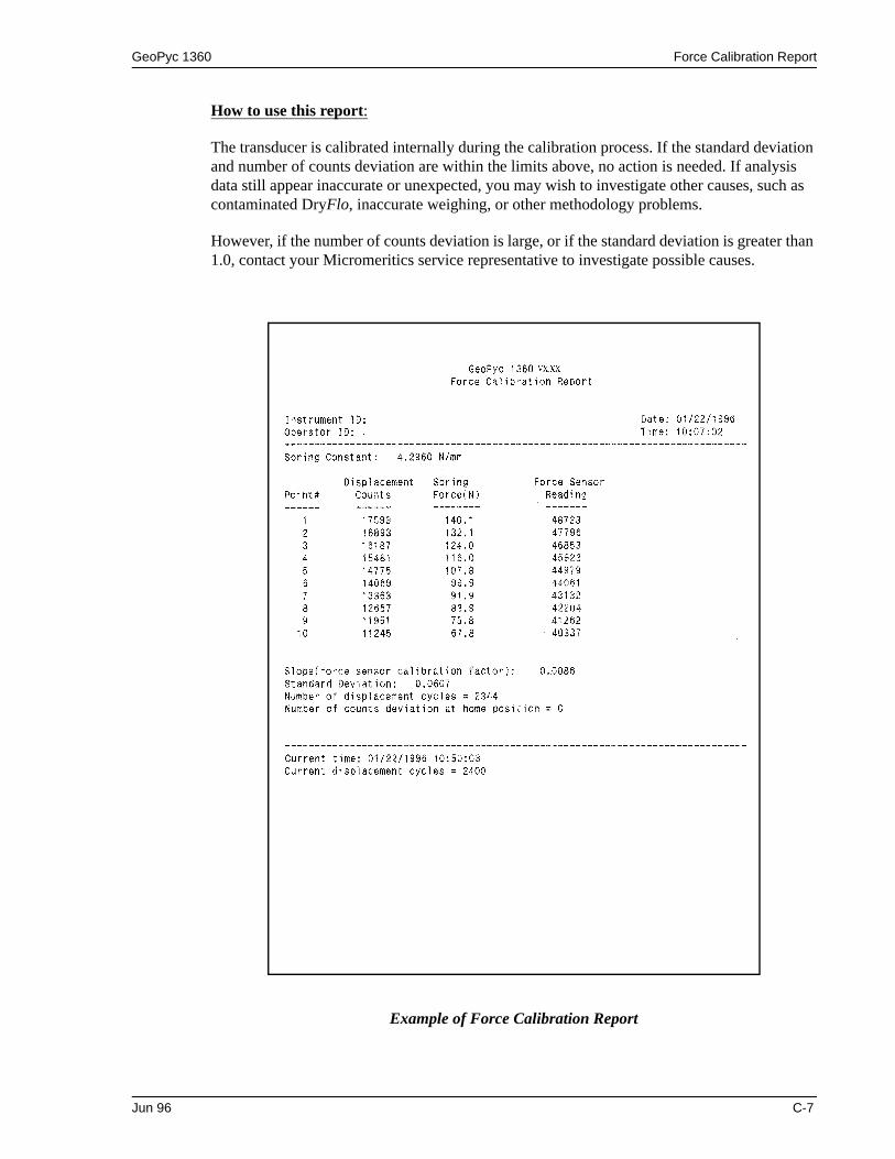
GeoPyc 1360 Force Calibration Report
How to use this report:
The transducer is calibrated internally during the calibration process. If the standard deviation and number of counts deviation are within the limits above, no action is needed. If analysis data still appear inaccurate or unexpected, you may wish to investigate other causes, such as contaminated DryFlo, inaccurate weighing, or other methodology problems.
However, if the number of counts deviation is large, or if the standard deviation is greater than 1.0, contact your Micromeritics service representative to investigate possible causes.
Example of Force Calibration Report
Jun 96 C-7


GeoPyc 1360 Appendix D
D. FORMAT OF TRANSMITTED DATA
Data can be transmitted in one of three user-selectable formats — report, single column, or spreadsheet. The report format is identical to the printed report. Single-column and spread-sheet are in ASCII-delimited format. Spreadsheet format is suitable for direct import into many popular spreadsheets.
In all tables, units are as follows:
Envelope Density (Analysis) Report
Date DD/MM/YYTime HH:MM:SSPressure mmHgElapsed Time seconds
Record Number Information Conveyed Form
1 Report title 20 characters
2 Instrument model number and software version number 20 characters
3 Report type (=1) 1 integer
4 Instrument 8 characters
5 Date 10 characters
6 Operator 8 characters
7 Time 8 characters
8 Customer 8 characters
9 Absolute density 1 floating point
10 Sample 20 characters
11 Sample weight 1 floating point
12-13 Reserved 1 floating point
14 Blank Data Set 8 characters
15 Blank Data Source 1 integer
16 Number of preparation cycles 1 integer
17 Number of measurement cycles 1 integer
18 Chamber Diameter 1 floating point
19 Zero Depth 1 floating point
20 Consolidation force 1 floating point
21 Conversion factor 1 floating point
22 Chamber/Medium weight 1 floating point
Jun 96 D-1

Appendix D GeoPyc 1360
Record Number Information Conveyed Form
23 Average volume 1 floating point
24 Volume standard deviation 1 floating point
25 Average density 1 floating point
26 Density standard deviation 1 floating point
27 Specific Pore Volume 1 floating point
28 Percent porosity 1 floating point
29 Percent Sample Volume 1 floating point
30-31 Reserved 1 floating point
(Single column)For I=1 to Number of complete runs
32 Blank counts 1 integer
33 Sample counts 1 integer
34 Volume 1 floating point
35 Volume deviation 1 floating point
36 Envelope density 1 floating point
37 Envelope density deviation 1 floating point
End for 1
(Spreadsheet)
32 Carriage return/Line Feed
33 Carriage return/Line Feed
34 Carriage return/Line Feed
For I=1 to Number of complete runs
35a Blank counts 1 integer
35b Sample counts 1 integer
35c Volume 1 floating point
35d Volume deviation 1 floating point
35e Envelope density 1 floating point
35f Envelope density deviation 1 floating point
End for 1
D-2 Jun 96

GeoPyc 1360 Appendix D
Calibration Report
Record Number Information Conveyed Form
1 Report title 20 characters2 Instrument model number and software version number 20 characters3 Report type (=2) 1 integer4 Instrument 8 characters5 Date 10 characters6 Operator 8 characters7 Time 8 characters8 Customer 8 characters9 Absolute Density 1 floating point10 Sample 20 characters11 Sample Weight 1 floating point12-13 Reserved 1 floating point14 Blank Data Set 8 characters15 Blank Data Source1 integer 1616 Number of preparation cycles 1 integer17 Number of measurement cycles 1 integer18 Calibration Volume 1 floating point19 Percent porosity 1 floating point20 Consolidation force 1 floating point21 Conversion factor 1 floating point22 Chamber/Medium weight 1 floating point23 Average volume 1 floating point24 Volume standard deviation 1 floating point25 Volume error 1 floating point26 New conversion factor 1 floating point27-28 Reserved 1 floating point
(Single column)For I=1 to Number of complete runs
29 Blank counts 1 integer30 Sample counts 1 integer31 Volume 1 floating point32 Volume deviation 1 floating point
End for 1
Jun 96 D-3

Appendix D GeoPyc 1360
Zero Depth Report
Record Number Information Conveyed Form
(Spreadsheet)
29 Carriage return/Line Feed
30 Carriage return/Line Feed
31 Carriage return/Line Feed
For I=1 to Number of complete runs
32a Blank counts 1 integer
32b Sample counts 1 integer
32c Volume 1 floating point
32d Volume deviation 1 floating point
End for 1
Record Number Information Conveyed Form
1 Report title 20 characters
2 Instrument model number and software version number 20 characters
3 Report type (=3) 1 integer
4 Instrument 8 characters
5 Date 10 characters
6 Time 8 characters
(Single column)For I=1 to 5
7-11 Chamber diameter 1 floating point
12-16 Zero depth 1 floating point
End for 1
(Spreadsheet)
7 Carriage return/Line Feed
8 Carriage return/Line Feed
9 Carriage return/Line Feed
For I=1 to 5
10a Chamber diameter 1 floating point
10b Zero depth 1 floating point
End for 1
D-4 Jun 96

GeoPyc 1360 Appendix D
Force Calibration Report
Record Number Information Conveyed Form
1 Report title 20 characters
2 Instrument model number and software version number 20 characters
3 Report type 1 integer
4 Instrument 8 characters
5 Operator 8 characters
6 Date 10 characters
7 Time 8 characters
8 Spring constant 1 floating point
9 Force sensor calibration factor 1 floating point
10 Standard deviation 1 floating point
11 Number of displacement cycles 1 long integer
12 Home position deviation 1 integer
(Single column)For I=1 to Number of complete runs
13 Point Number 1 integer
14 Displacement counts 1 integer
15 Spring force 1 floating point
16 Force sensor reading 1 integer
End for 1
(Spreadsheet)
13 Carriage return/Line Feed
14 Carriage return/Line Feed
15 Carriage return/Line Feed
For I=1 to Number of complete runs
16a Point Number 1 integer
16b Displacement counts 1 integer
16c Spring force 1 floating point
16d Force sensor reading 1 integer
End for 1
Jun 96 D-5

Appendix D GeoPyc 1360
Blank Data Set Listing
Record Number Information Conveyed Form
1 Report title 20 characters
2 Instrument model number and software version number 20 characters
3 Report type (=0) 1 integer
4 Instrument 8 characters
5 Date 10 characters
6 Time 8 characters
7 Blank data set 8 characters
8 Blank data set number 1 integer
9 Number of prep. cycles 1 integer
10 Consolidation force 1 floating point
11 Conversion factor 1 floating point
12-13 Reserved 1 floating point
(Single column)For I=1 to 10
14-23 Chamber/Medium Weight 1 floating point
End for 1
For J=1 to 20
For I=1 to 10
24-223 Blank count 1 integer
End for 1
End for J
(Spreadsheet)
14 Carriage return/Line Feed
15 Carriage return/Line Feed
16 Carriage return/Line Feed
17a Chamber/Medium Weight 1 floating point
17b Chamber/Medium Weight 1 floating point
17c Chamber/Medium Weight 1 floating point
17d Chamber/Medium Weight 1 floating point
17e Chamber/Medium Weight 1 floating point
17f Chamber/Medium Weight 1 floating point
17g Chamber/Medium Weight 1 floating point
17h Chamber/Medium Weight 1 floating point
17i Chamber/Medium Weight 1 floating point
D-6 Jun 96

GeoPyc 1360 Appendix D
Record Number Information Conveyed Form
17j Chamber/Medium Weight 1 floating point
For J=1 to 20
18a Blank count 1 integer
18b Blank count 1 integer
18c Blank count 1 integer
18d Blank count 1 integer
18e Blank count 1 integer
18f Blank count 1 integer
18g Blank count 1 integer
18h Blank count 1 integer
18i Blank count 1 integer
18j Blank count 1 integer
End for J
Jun 96 D-7


GeoPyc 1360 Index
INDEX
Numerics2nd key, 3-2, 3-4
AAgitator state, C-1Analysis chamber
cleaning, 3-13handling, 3-13selecting the correct size, 3-13
Analyzerturning on and off, 3-1
Analyzer warmup, 3-1
BBlank Data Set Listing, 5-4
example of report, 5-5printing, 5-2Transmitted data format, D-6
Blank data set, storing, 4-14Blank run, 1-4, 4-1
storing data from, 4-14, 4-17
CCalibration
choosing object, 4-5starting run, 4-6
Calibration Report, 5-6example of, 5-7printing, 4-9, 5-1transmitted data format, D-3transmitting, 4-9
Calibration run, 1-5, 4-1, 4-4starting, 4-6
Canceling a run, 4-23Cautions, defined, 1-2Chamber diameter
determining, 3-14internal, 1-7
Chamber/plungerhandling, 3-18mounting on analyzer, 3-16removing from analyzer, 3-17selecting, 3-13
Cleaninganalysis chamber, 3-13
analyzer, 3-1Cold flow, 3-19Consolidation cycles, 1-5Consolidation force, 1-5, 3-21
typical, 3-21Conventions, operator’s manual, 1-2Conversion factor, 1-5, 4-4, 4-12, 4-18
DData entry, 3-4Data, transmitted, 5-3Date, entering, 3-6Displacement volume, 1-4Drive screw calculations, 1-5DryFlo, 1-4
handling, 3-10how much to use, 3-11use only, 3-11weighing, 4-16
EEnvelope density, 1-4
calculating, 1-4, A-1Envelope Density Report, 5-8
example of, 5-9printing, 4-13, 5-1transmitted data format, D-1transmitting, 4-13
Envelope volume, 1-4Equipment
damage and loss, 2-1description, 1-3inspecting, 2-1location, 2-3returns, 2-1setup, 2-3unpacking, 2-1
Error messages, B-1Exit manual mode, C-5Exposed materials, 1-8
FForce
display, C-1transducer, C-4
May 09 Index-1

Index GeoPyc 1360
Force Calibration Report, C-6transmitted data format, D-5
Frequency, 1-7Function keys, 3-3
GGeoPyc
advantages of using, 1-4verifying operation, 4-21
HHome indicator, C-1Humidity, 1-7
IInstrument ID, 3-6
KKeypad, 3-1
description of keys, 3-3
LLanguage, selecting, 1-3, 3-5Limit switch indicator, C-1Location, selecting, 2-3
MManual operations, C-1Measurement method, 1-5Memory Card, installing, 2-3Moisture adsorbed by sample, 3-22Mounting chamber/plunger, 3-16Move, C-1Move number of steps, C-2Move to home, C-2Move until force achieved, C-3
NNotes, defined, 1-2
OOperating tips, 4-20Operator’s manual
conventions, 1-2organization, 1-1
Output optionscalibration run, 4-9sample run, 4-13stored blank data, 4-19
PPercent sample volume
selecting in system options, 3-7Percentage porosity, 1-4, A-1Piston
replacing, 3-20tightening, 3-20
Plungerassembly, 3-19displacement motor, C-1handling, 3-13inserting into chamber, 3-14
Position display, C-1Power, 1-7Power cord, installing, 2-3Preparation cycles, 1-5
specifying number of, 3-7Print Force Calibration Report, C-5Printer, connecting, 2-4Printing reports, 5-1
RReport Options setup dialog, 3-8
Setup dialog, 3-5Reports, 1-6
Blank data set listing, 5-4Calibration, 5-6Envelope density, 5-8Force calibration, C-6printing, 5-1title, 3-6transmitting data, 5-3Zero depth, 5-10
Reproducibilty, 1-7RS-232 Data Transmission, 1-3
connecting cable, 2-4Runs, types of, 4-1
SSample
placing in chambers, 3-14quantity, 4-20run, 1-4, 4-1size, 4-20weight, 1-4, 3-22, 4-10
Index-2 May 09

GeoPyc 1360 Index
Sealing, checking, 3-19Second key, 3-2, 3-4Self-check, 3-1Set agitation rotation amplitude, C-3Set movement speed, C-3Setup dialog
accessing, 3-5Report options, 3-5, 3-8System options, 3-5Transmission options, 3-5, 3-9
Setup, software, 3-5Specific pore volume, 1-4, A-1Specifications, 1-7Spring standard, C-4Stepper motor, 1-5, A-1System configuration, 1-3System Options setup dialog, 3-5
Setup dialog, 3-5
TTemperature, 1-7Template, keypad, 2-4Time, entering, 3-6Tips for Successful Operation, 4-20Toggle agitation on/off, C-3Toggle force display units, C-3Transmission Options setup dialog, 3-9
Setup dialog, 3-5Transmitted data, 5-3
format, D-1Troubleshooting, 4-20
Verifying Instrument Operation, 4-21
UUsable length of chambers, 1-7
VVoltage, 1-7
WWarnings, defined, 1-2Weighing samples, 3-22
ZZero depth, 1-4, 4-1
sets, 4-2Zero depth report, 4-3, 5-10
example of, 5-11
printing, 5-1transmitted data format, D-4
Zero depth run, 4-2
May 09 Index-3
