geometry of aerial...
TRANSCRIPT
Geometry of Aerial photogrammetry
Panu Srestasathiern, PhD.Researcher
Geo-Informatics and Space Technology Development Agency (Public Organization)
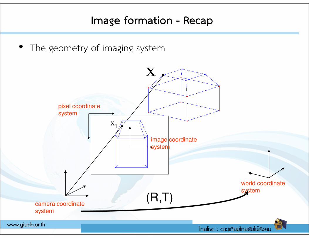
Image formationImage formation -- RecapRecap
• The geometry of imaging system
pixel coordinate
system
x
world coordinate
system
camera coordinate
system
(R,T)
image coordinate
system
x1
Types of aerial Types of aerial photographphotograph
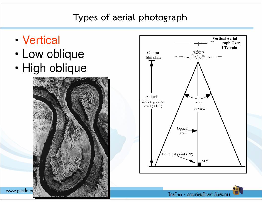
• Vertical
• Low oblique
• High oblique
Altitude
above-ground-
Vertical Aerial
Photograph Over
Level Terrain
Camera
film plane
Altitude
above-ground-
Vertical Aerial
Photograph Over
Level Terrain
Camera
film plane
above-ground-
level (AGL)
90°
Principal point (PP)
Optical
axis
field
of view
above-ground-
level (AGL)
90°
Principal point (PP)
Optical
axis
field
of view
Types of aerial Types of aerial photographphotograph
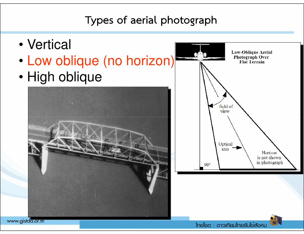
• Vertical
• Low oblique (no horizon)
• High oblique
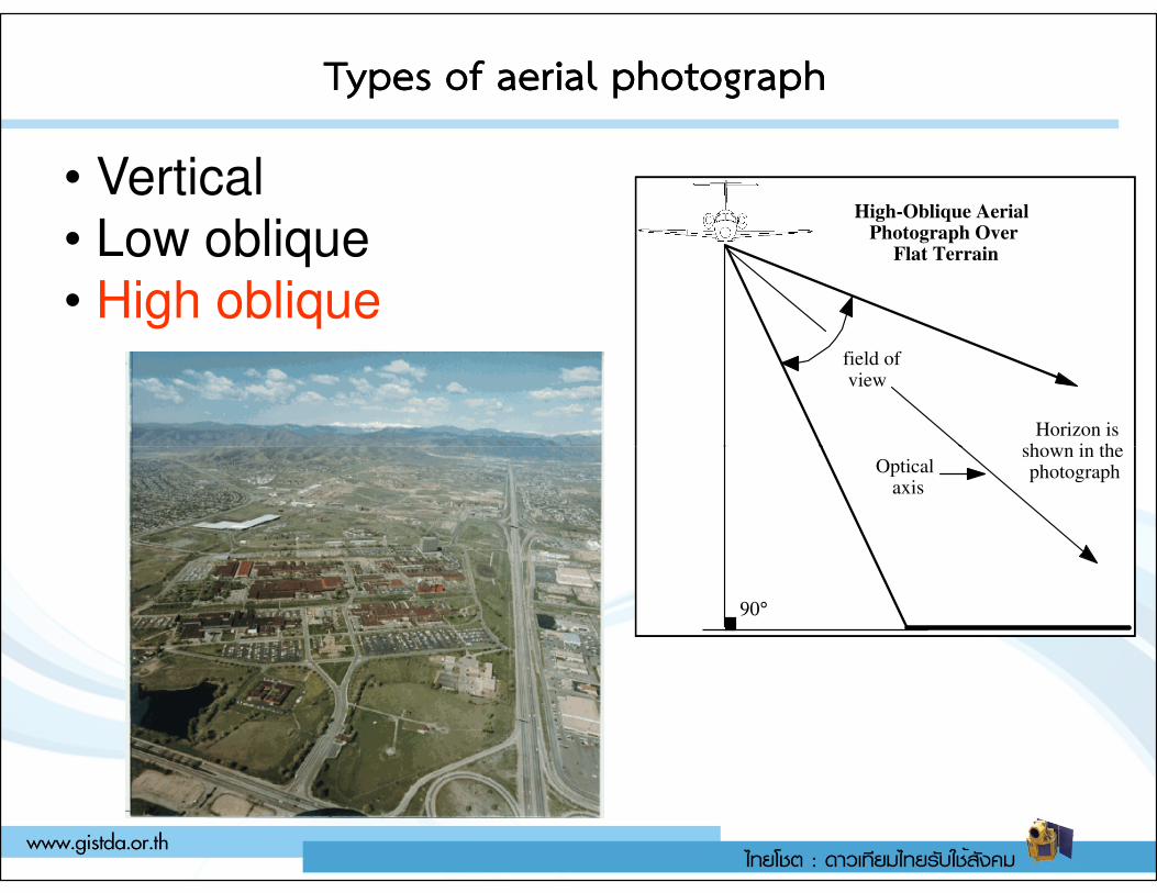
Types of aerial Types of aerial photographphotograph
• Vertical
• Low oblique
• High oblique
High-Oblique Aerial Photograph Over
Flat Terrain
Horizon is shown in the
field of view
High-Oblique Aerial Photograph Over
Flat Terrain
Horizon is shown in the
field of view
90°
shown in the photographOptical
axis
90°
shown in the photographOptical
axis
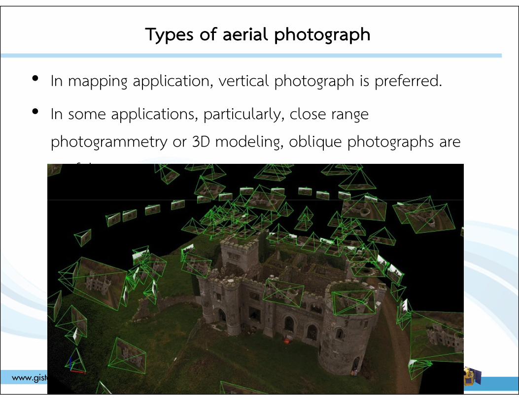
Types of aerial photographTypes of aerial photograph
• In mapping application, vertical photograph is preferred.
• In some applications, particularly, close range photogrammetry or 3D modeling, oblique photographs are useful.
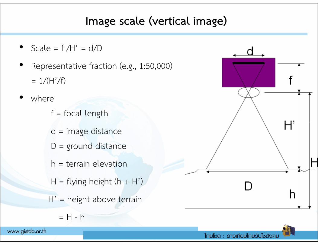
Image Image scale (vertical image)scale (vertical image)
• Scale = f /H’ = d/D
• Representative fraction (e.g., 1:50,000) = 1/(H’/f)
• where f = focal length
d = image distanceD = ground distance
h = terrain elevation
H = flying height (h + H’)
H’ = height above terrain
= H - h
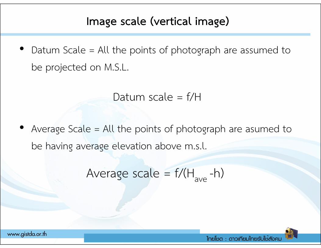
Image scale (vertical image)Image scale (vertical image)
• Datum Scale = All the points of photograph are assumed to be projected on M.S.L.
• Average Scale = All the points of photograph are asumed to
Datum scale = f/H
• Average Scale = All the points of photograph are asumed to be having average elevation above m.s.l.
Average scale = f/(Have -h)
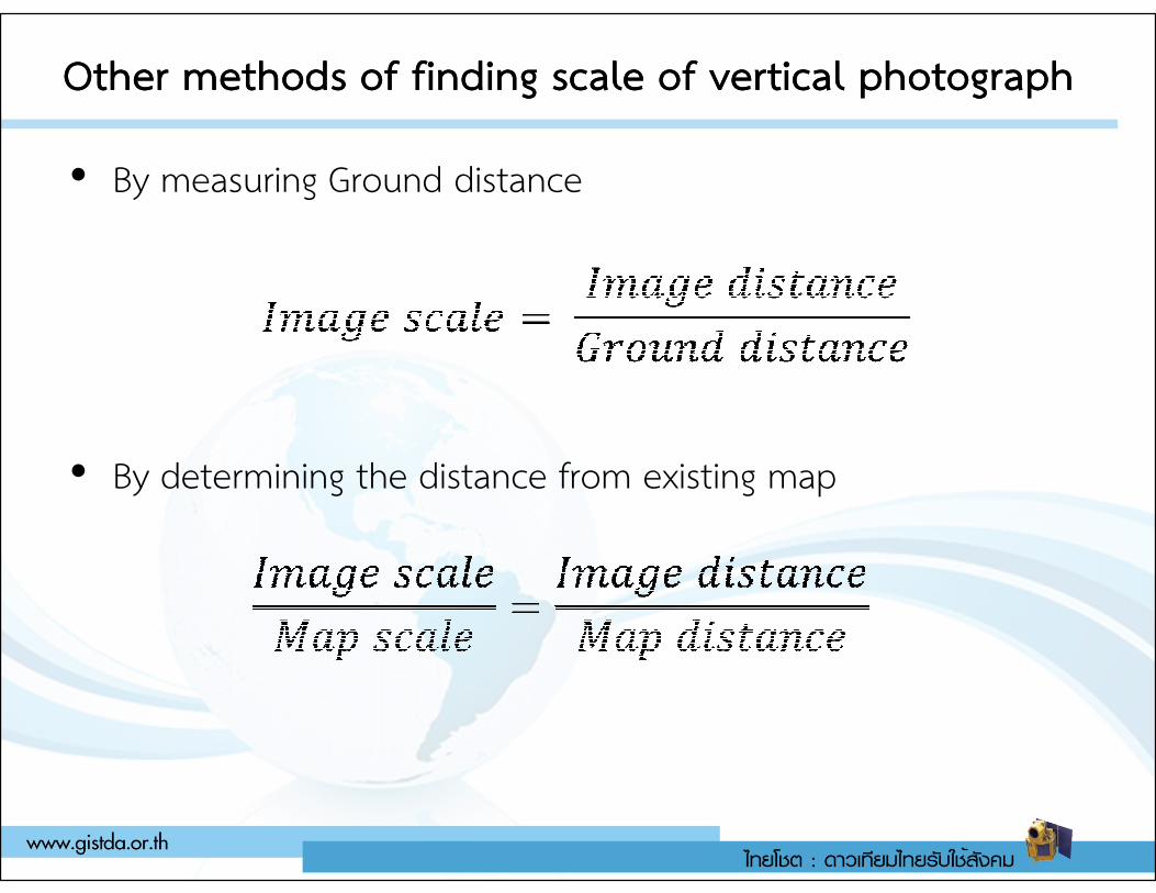
Other methods of finding scale of vertical photographOther methods of finding scale of vertical photograph
• By measuring Ground distance
• By determining the distance from existing map• By determining the distance from existing map
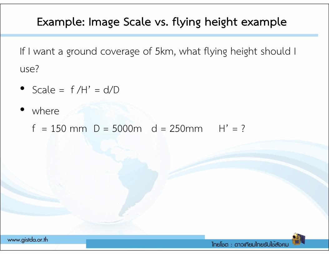
Example: Image Scale vs. flying height exampleExample: Image Scale vs. flying height example
If I want a ground coverage of 5km, what flying height should I use?
• Scale = f /H’ = d/D
• where f = 150 mm D = 5000m d = 250mm H’ = ?f = 150 mm D = 5000m d = 250mm H’ = ?
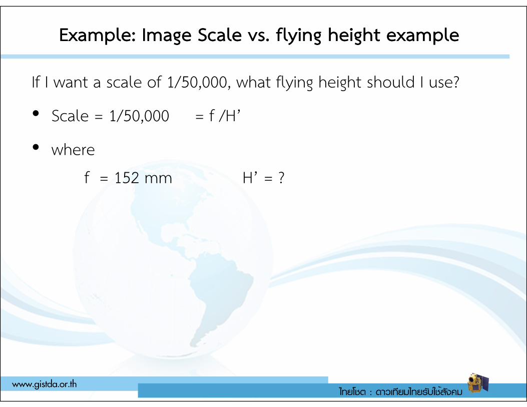
Example: Image Scale vs. flying height exampleExample: Image Scale vs. flying height example
If I want a scale of 1/50,000, what flying height should I use?
• Scale = 1/50,000 = f /H’
• where f = 152 mm H’ = ?
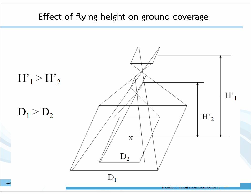
Effect of flying height on ground coverageEffect of flying height on ground coverage
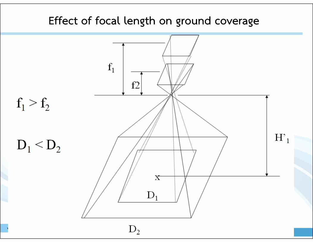
Effect of focal length on ground coverageEffect of focal length on ground coverage
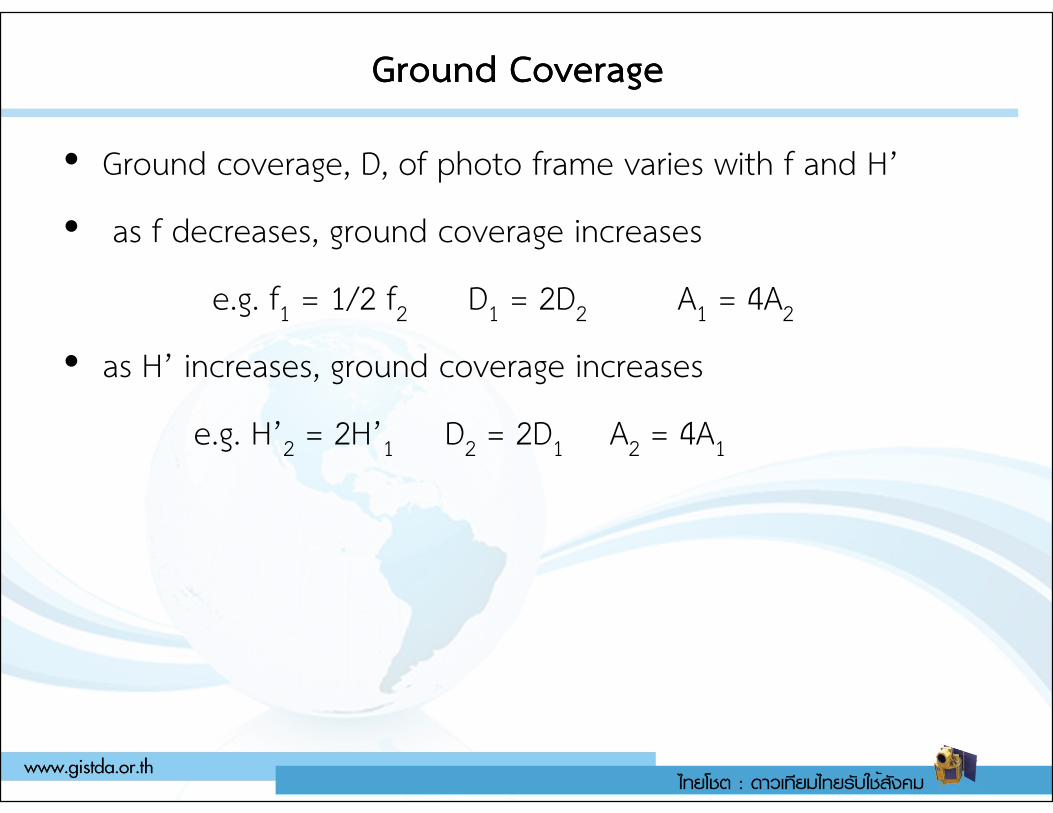
Ground CoverageGround Coverage
• Ground coverage, D, of photo frame varies with f and H’
• as f decreases, ground coverage increases
e.g. f1 = 1/2 f2 D1 = 2D2 A1 = 4A2
• as H’ increases, ground coverage increases
e.g. H’ = 2H’ D = 2D A = 4Ae.g. H’2 = 2H’1 D2 = 2D1 A2 = 4A1
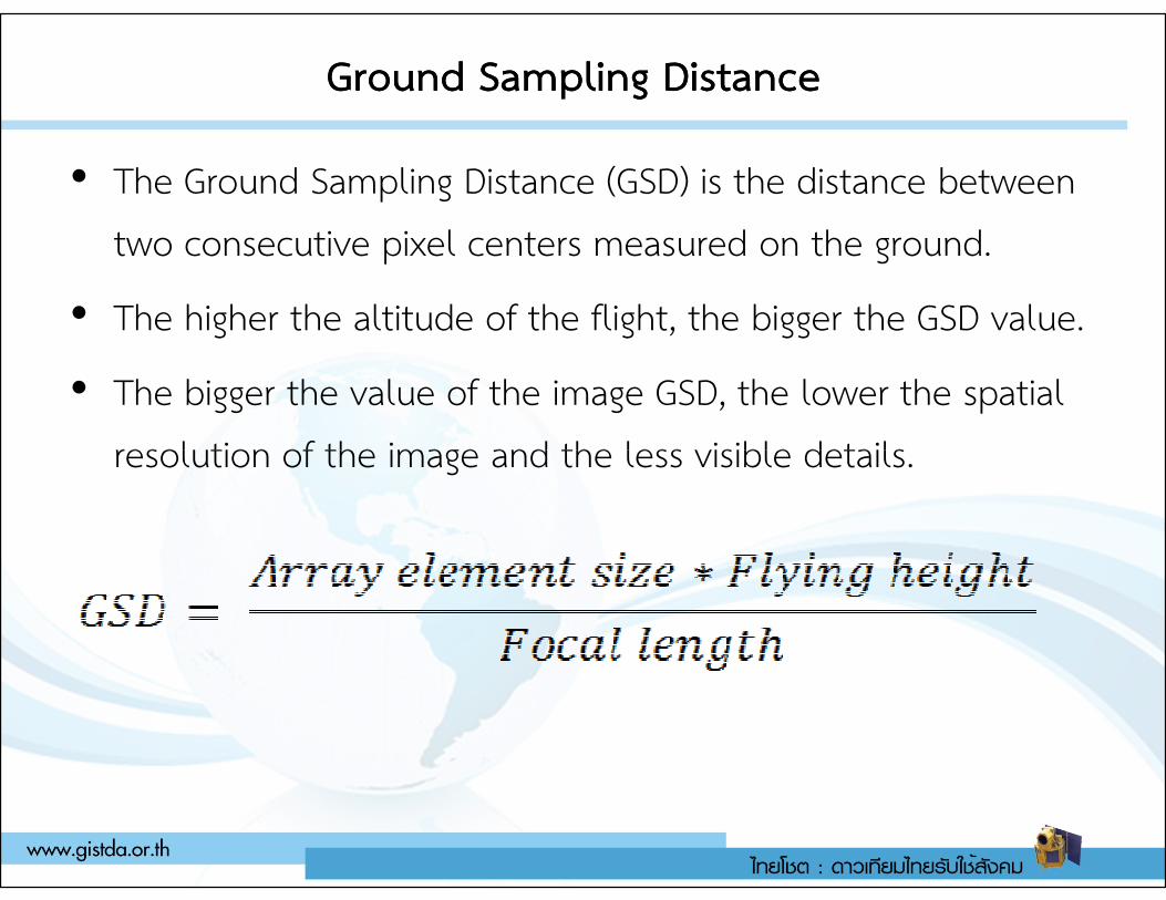
Ground Sampling DistanceGround Sampling Distance
• The Ground Sampling Distance (GSD) is the distance between two consecutive pixel centers measured on the ground.
• The higher the altitude of the flight, the bigger the GSD value.
• The bigger the value of the image GSD, the lower the spatial resolution of the image and the less visible details. resolution of the image and the less visible details.
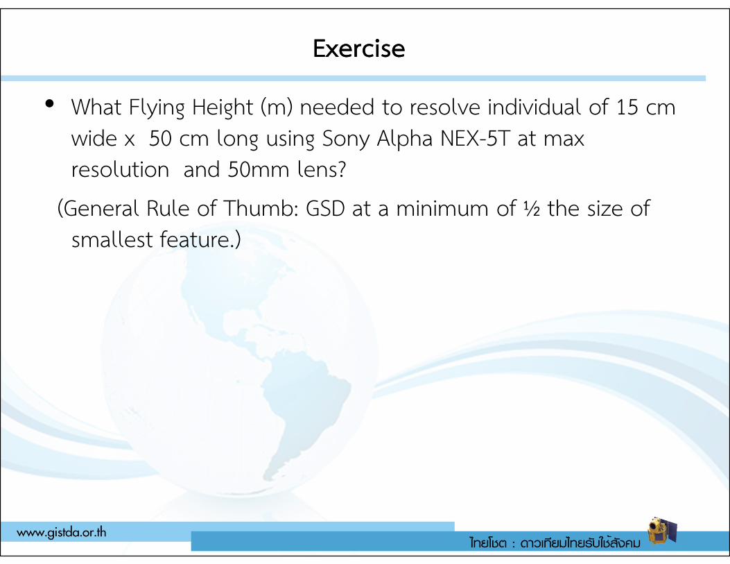
ExerciseExercise
• What Flying Height (m) needed to resolve individual of 15 cm wide x 50 cm long using Sony Alpha NEX-5T at max resolution and 50mm lens?
(General Rule of Thumb: GSD at a minimum of ½ the size of smallest feature.)
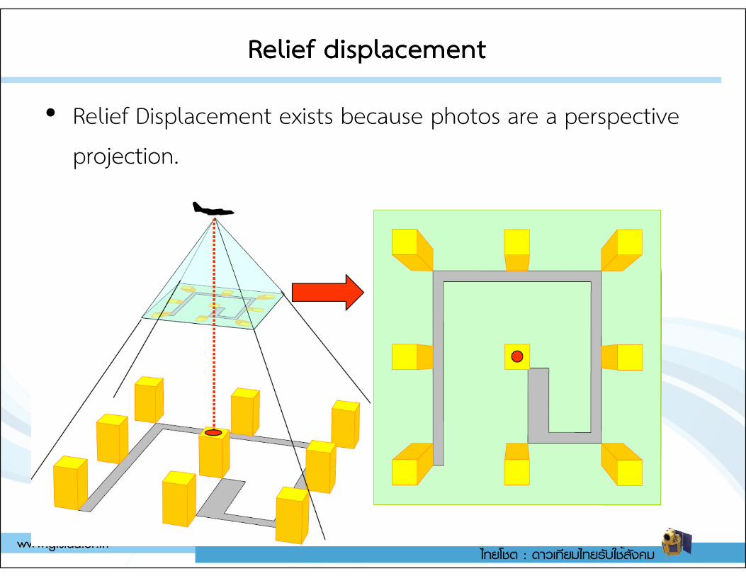
Relief displacementRelief displacement
• Relief Displacement exists because photos are a perspective projection.
Relief displacement Relief displacement
• The scale of an aerial photograph is partly a function of flying height.
• Thus, variations in elevation cause variations in scale on aerial photographs. Specifically, the higher the elevation of an object, the farther the object will be displaced from its actual object, the farther the object will be displaced from its actual position away from the principal point of the photograph (the point on the ground surface that is directly below the camera lens).
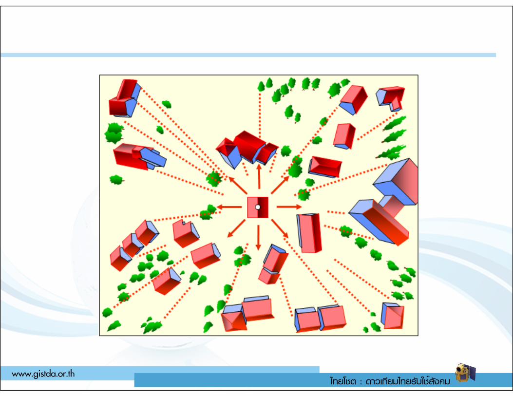
Relief displacementRelief displacement
Aerial triangulationAerial triangulation
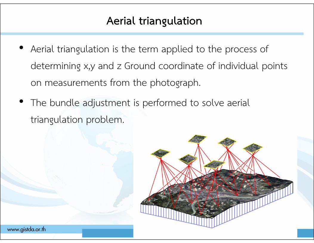
• Aerial triangulation is the term applied to the process of determining x,y and z Ground coordinate of individual points on measurements from the photograph.
• The bundle adjustment is performed to solve aerial triangulation problem.triangulation problem.
What is Bundle Adjustment ?What is Bundle Adjustment ?
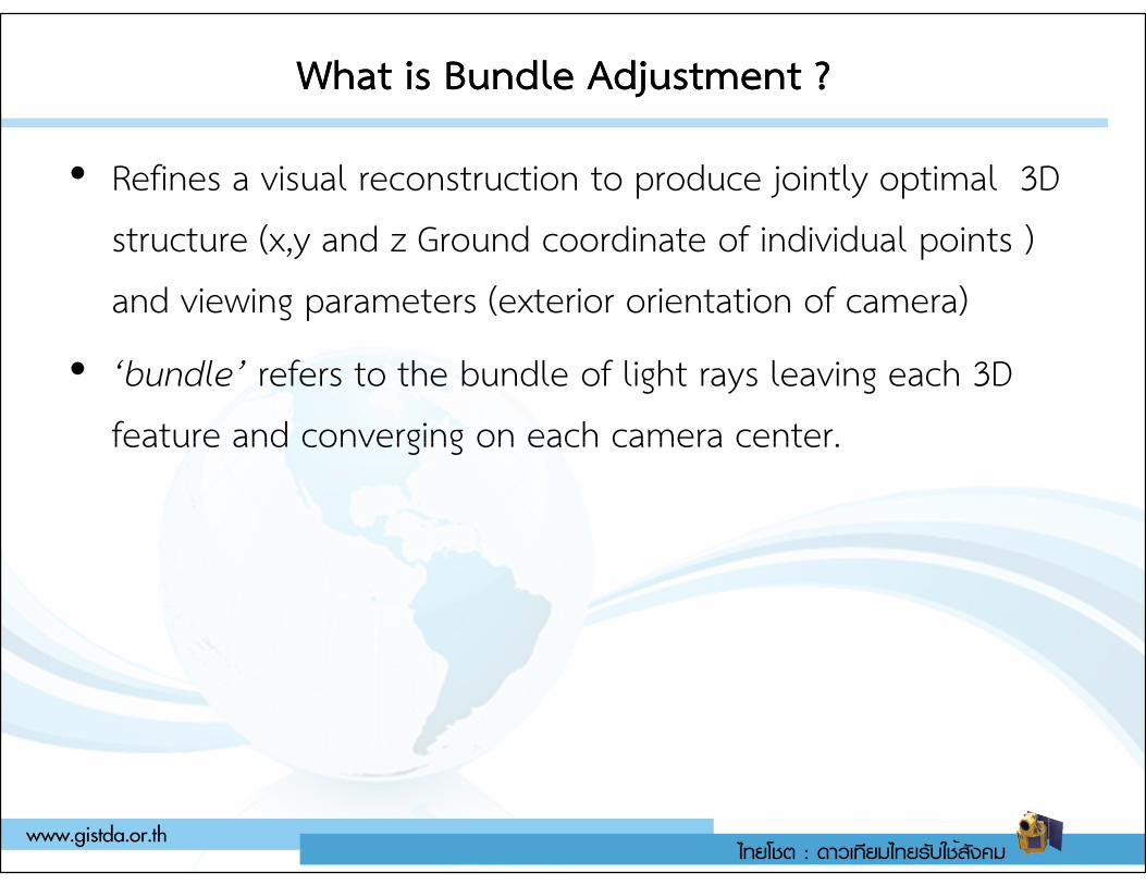
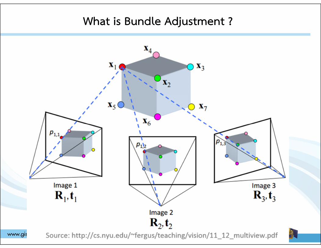
• Refines a visual reconstruction to produce jointly optimal 3D structure (x,y and z Ground coordinate of individual points ) and viewing parameters (exterior orientation of camera)
• ‘bundle’ refers to the bundle of light rays leaving each 3D feature and converging on each camera center. feature and converging on each camera center.
What is Bundle Adjustment ?What is Bundle Adjustment ?
What is Bundle Adjustment ?What is Bundle Adjustment ?
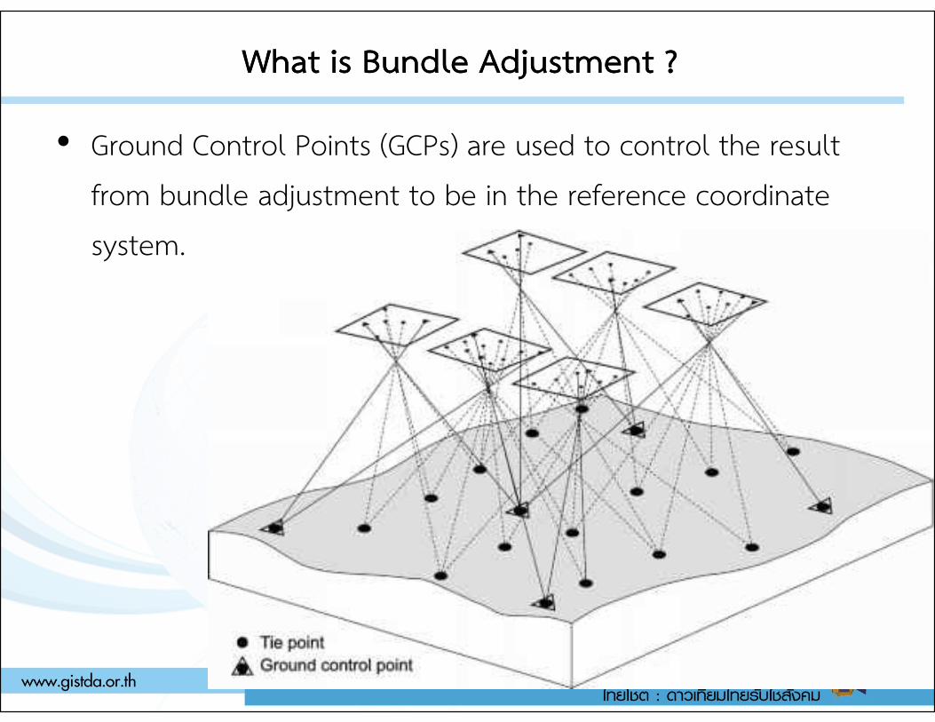
• Ground Control Points (GCPs) are used to control the result from bundle adjustment to be in the reference coordinate system.
Bundle adjustment without GCPBundle adjustment without GCP
• Without GCP, bundle adjustment can be performed; but the recovered 3D structure and camera orientations are in independent coordinate system.
• The camera orientation estimated without GCP is called relative orientation. relative orientation.
• Bundle adjustment with GCP is then called absolute orientation.
• In other words, relative orientation is the process of orienting images relative to one another.
• Without GCP, the scale of 3D object is incorrect.
Airborne GPS support Aerial triangulationAirborne GPS support Aerial triangulation
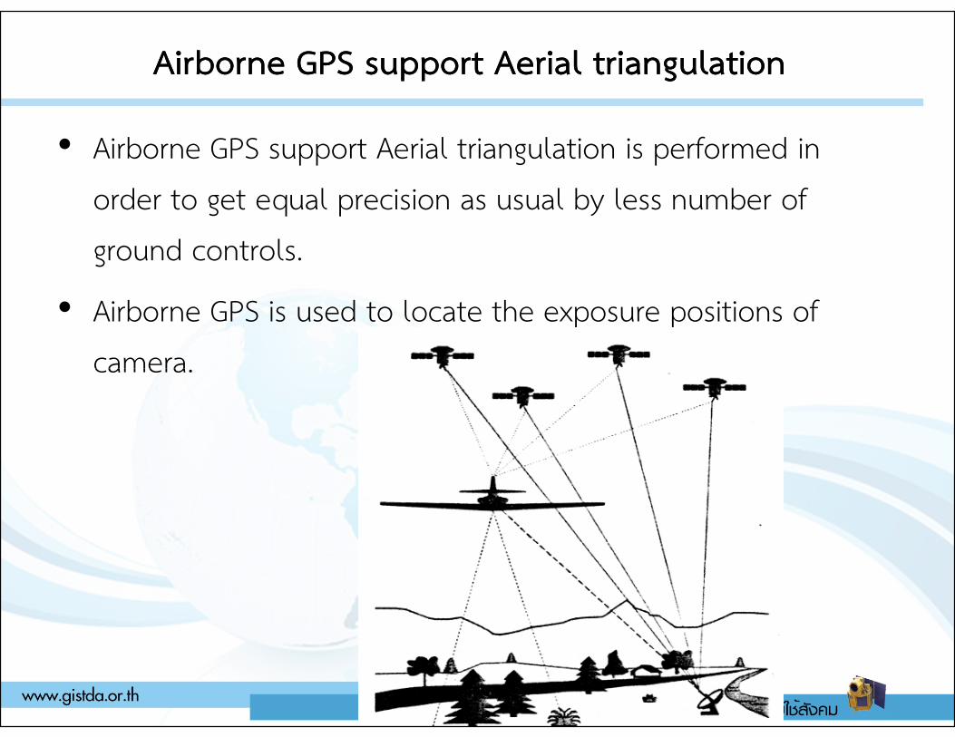
• Airborne GPS support Aerial triangulation is performed in order to get equal precision as usual by less number of ground controls.
• Airborne GPS is used to locate the exposure positions of camera.camera.
Airborne GPS support Aerial triangulationAirborne GPS support Aerial triangulation
• Airborne GPS support Aerial triangulation is also called “Direct
geo-referencing.”
• Aerial triangulation using GCP only is also called “In-direct
geo-referencing.”
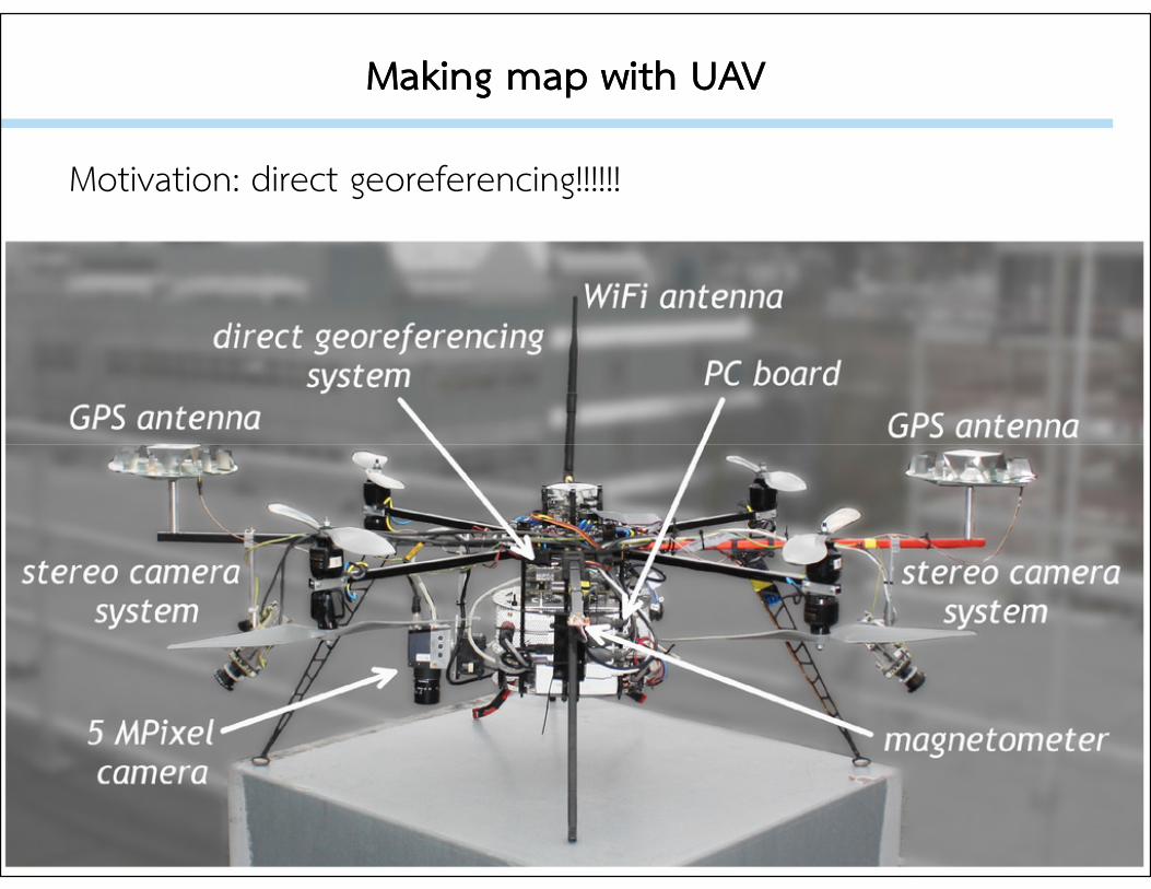
Making map with UAVMaking map with UAV
Motivation: direct georeferencing!!!!!!
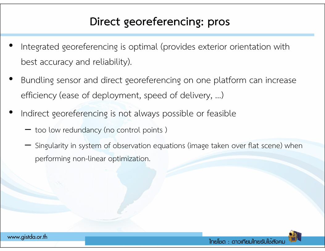
Direct Direct georeferencinggeoreferencing: pros: pros
• Integrated georeferencing is optimal (provides exterior orientation with best accuracy and reliability).
• Bundling sensor and direct georeferencing on one platform can increase efficiency (ease of deployment, speed of delivery, …)
• Indirect georeferencing is not always possible or feasible
– too low redundancy (no control points )– too low redundancy (no control points )
– Singularity in system of observation equations (image taken over flat scene) when performing non-linear optimization.
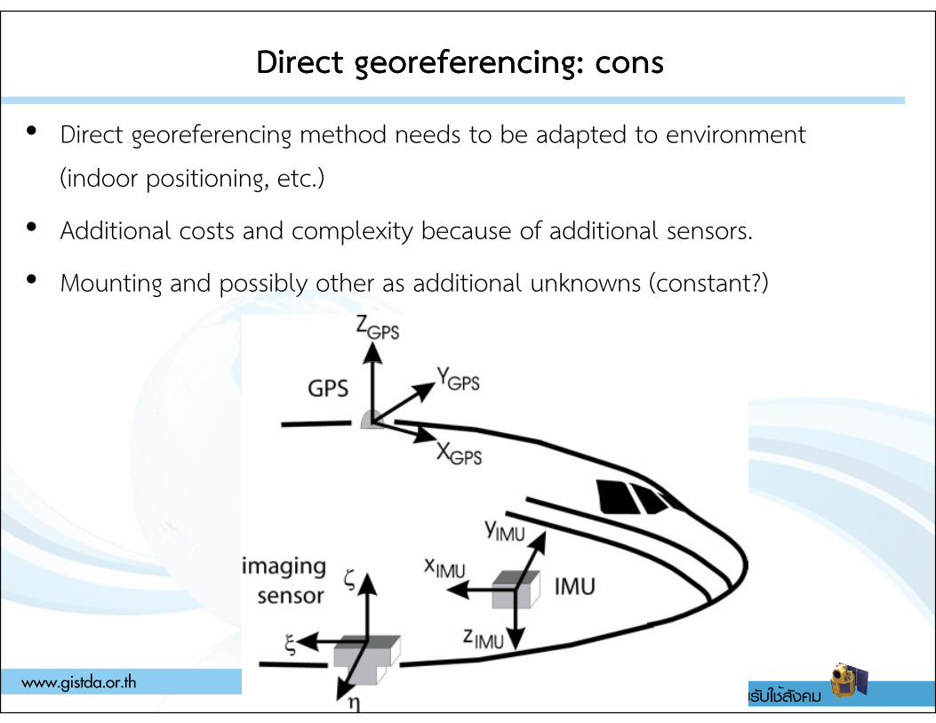
Direct Direct georeferencinggeoreferencing: cons: cons
• Direct georeferencing method needs to be adapted to environment (indoor positioning, etc.)
• Additional costs and complexity because of additional sensors.
• Mounting and possibly other as additional unknowns (constant?)
Where is the exterior orientation stored?Where is the exterior orientation stored?
• To perform direct geo-referencing, the GPS/INS information (exterior orientation parameters) must be imported to processing software.
• There are two ways to store exterior orientation parameters:
– EXIF data– EXIF data
– Image geolocation file e.g., CSV text file
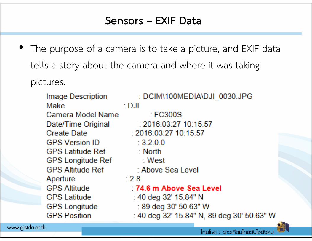
Sensors Sensors –– EXIF DataEXIF Data
• The purpose of a camera is to take a picture, and EXIF data tells a story about the camera and where it was taking pictures.
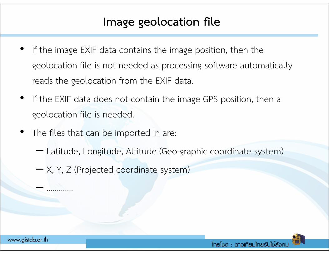
Image Image geolocationgeolocation filefile
• If the image EXIF data contains the image position, then the geolocation file is not needed as processing software automatically reads the geolocation from the EXIF data.
• If the EXIF data does not contain the image GPS position, then a geolocation file is needed.
• The files that can be imported in are:• The files that can be imported in are:
– Latitude, Longitude, Altitude (Geo-graphic coordinate system)
– X, Y, Z (Projected coordinate system)
– ………….
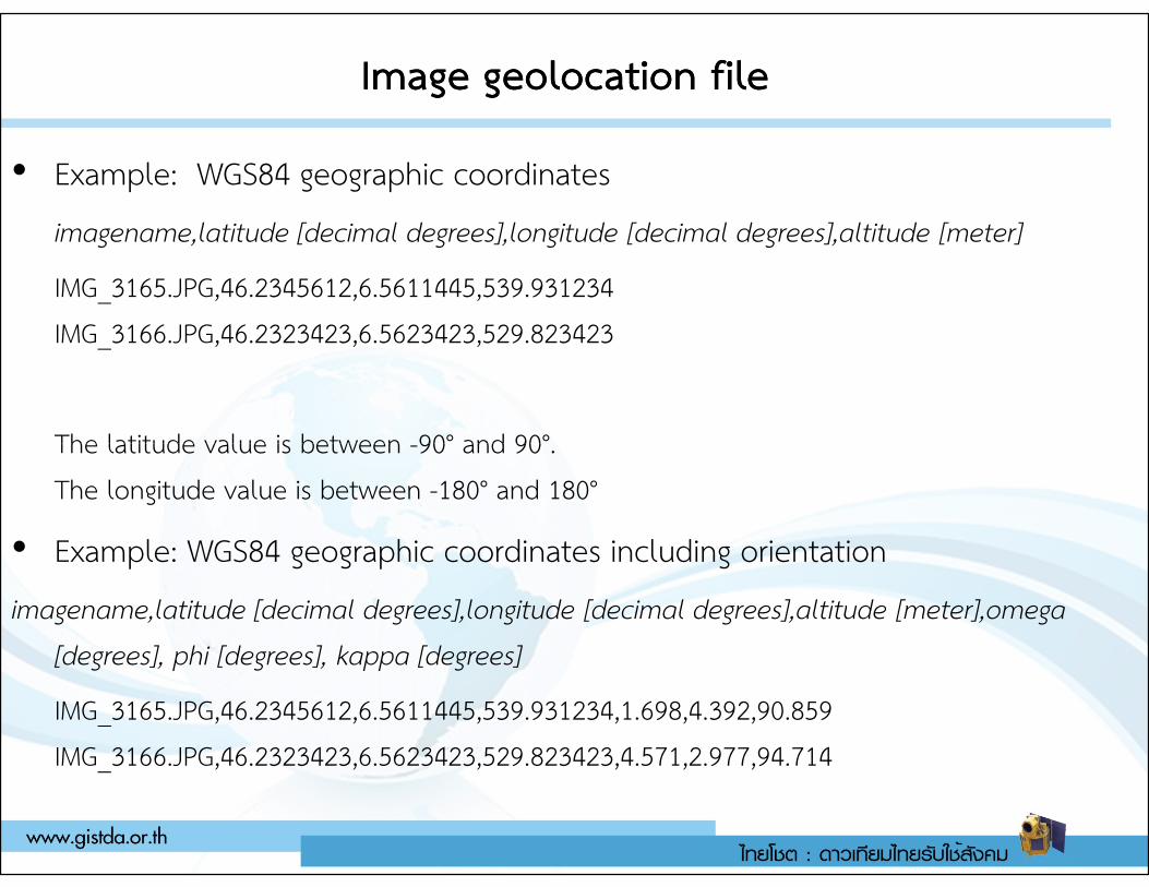
Image Image geolocationgeolocation filefile
• Example: WGS84 geographic coordinates
imagename,latitude [decimal degrees],longitude [decimal degrees],altitude [meter]
IMG_3165.JPG,46.2345612,6.5611445,539.931234IMG_3166.JPG,46.2323423,6.5623423,529.823423
The latitude value is between -90° and 90°.The latitude value is between -90° and 90°.The longitude value is between -180° and 180°
• Example: WGS84 geographic coordinates including orientation
imagename,latitude [decimal degrees],longitude [decimal degrees],altitude [meter],omega [degrees], phi [degrees], kappa [degrees]
IMG_3165.JPG,46.2345612,6.5611445,539.931234,1.698,4.392,90.859IMG_3166.JPG,46.2323423,6.5623423,529.823423,4.571,2.977,94.714
Photo overlapPhoto overlap
Endlap
• Endlap, also known as forward overlap, is the common image area on consecutive photographs along a flight strip.
• This overlapping portion of two successive aerial photos, which creates the three-dimensional effect necessary for which creates the three-dimensional effect necessary for mapping, is known as a stereomodel or more commonly as a “model.”
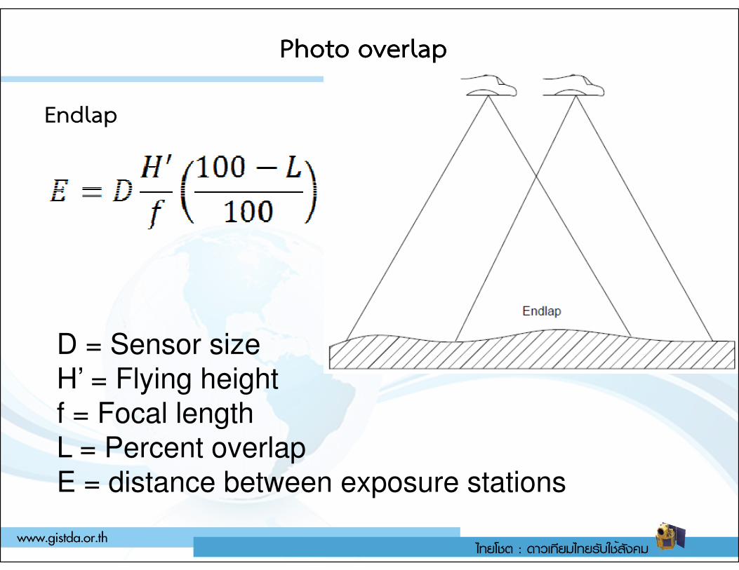
Photo overlapPhoto overlap
Endlap
D = Sensor sizeH’ = Flying heightf = Focal lengthL = Percent overlapE = distance between exposure stations
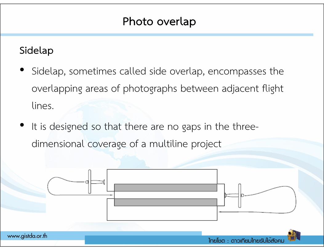
Photo overlapPhoto overlap
Sidelap
• Sidelap, sometimes called side overlap, encompasses the overlapping areas of photographs between adjacent flight lines.
• It is designed so that there are no gaps in the three-• It is designed so that there are no gaps in the three-dimensional coverage of a multiline project
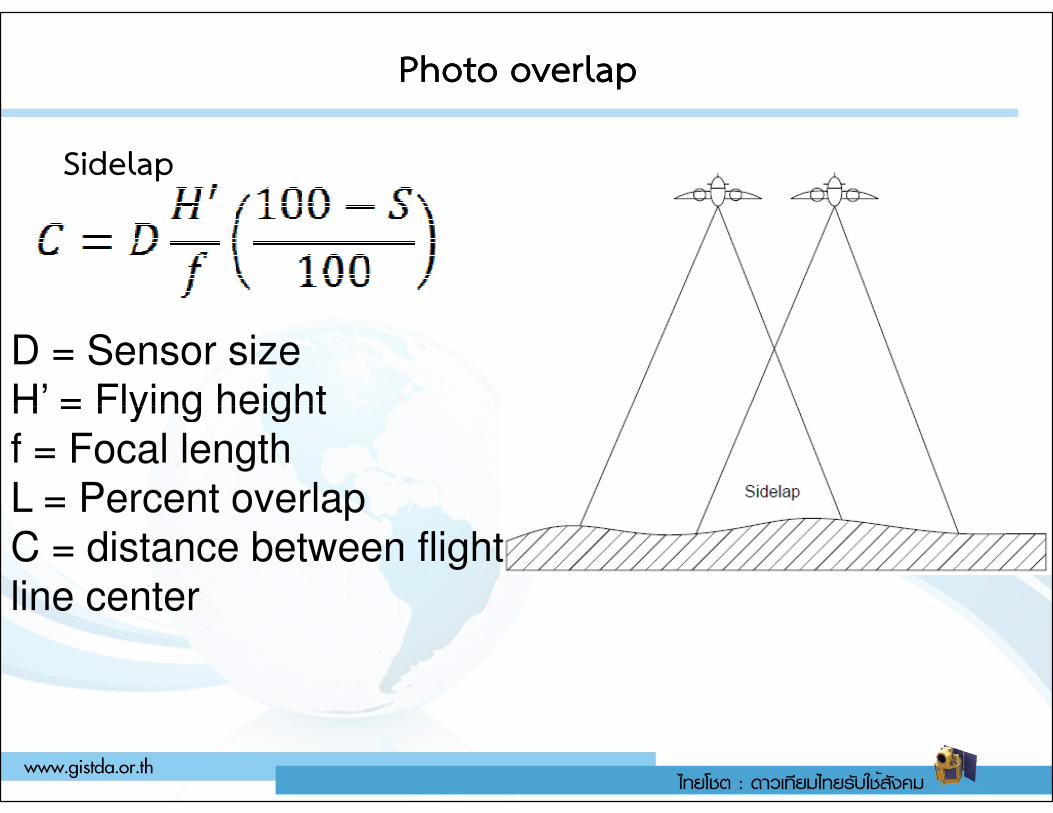
Photo overlapPhoto overlap
Sidelap
D = Sensor sizeH’ = Flying heightH’ = Flying heightf = Focal lengthL = Percent overlapC = distance between flight line center
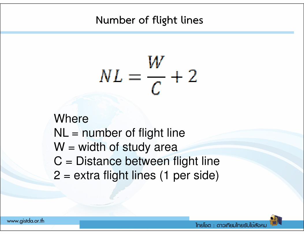
Number of flight linesNumber of flight lines
WhereWhereNL = number of flight lineW = width of study areaC = Distance between flight line2 = extra flight lines (1 per side)
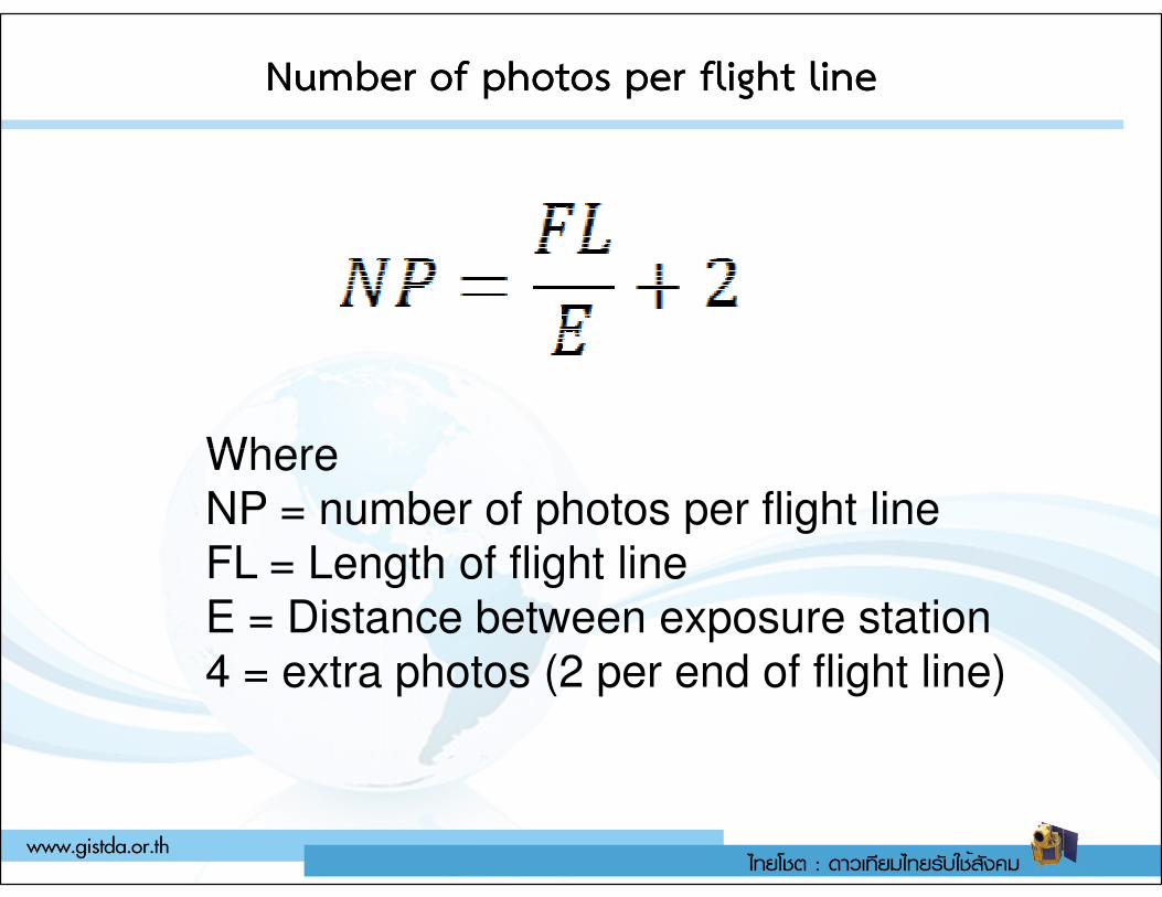
Number of photos per flight lineNumber of photos per flight line
WhereWhereNP = number of photos per flight lineFL = Length of flight lineE = Distance between exposure station4 = extra photos (2 per end of flight line)