geometrical product specifications (gps) · iso 1101:2012 as a non-uniform tolerance zone (figure...
TRANSCRIPT

1FIRST PUBLISHED IN MAY 2015
PIQ-ONLINE
GENERAL TOLERANCES IN THE GPS CONCEPT
PREFACEThe previously published articles about geometrical product
specifications explained fundamental standards of the GPS
concept required to describe geometrical characteristics
bull Geometrical product specifications (GPS) ndash an
incomplete survey
bull Geometrical product specifications (GPS) ndash ISO 8015
basic GPS standard
bull Geometrical product specifications (GPS) - ISO 14405-1
the general GPS standard for dimensional tolerancing of
linear sizes
bull Geometrical product specifications (GPS) ndash consequenc-
es on the tolerancing of features of size
bull Geometrical product specifications (GPS) ndash application
of geometrical tolerancing to step dimensions
GEOMETRICAL PRODUCT SPECIFICATIONS (GPS)DR-ING GUNTER EFFENBERGER | Q-DAS GMBH
Hardly any drawing does not refer to the tolerance classes
of the ISO 2768 standard for general tolerances However I
have recently received many queries about how these ldquooldldquo
standards (ISO edition issued in 1989) agree with current
general standards of the GPS system This article answers
this and many more questions relating to general tolerances
MEANING OF GENERAL TOLERANCES
On the one hand the eleventh principle or functional control
principle of the basic standard ISO 8015 demands
ldquothat the specification of a workpiece is complete when
all intended functions of the workpiece are described and
controlled with GPS specifications ldquo
This is the reason why any functional geometrical
characteristic is defined separately by means of the symbols
and tolerances the GPS system provides On the other hand
the third principle or definitive drawing principle says that
ldquoall specifications shall be indicated on the drawing using
GPS symbology Consequently requirements not specified on
the drawing cannot be enforced ldquo Note All numerical data are given in mm without
indicating this unit of measurement in the following
2 FIRST PUBLISHED IN MAY 2015
Interpreting this principle this means that drawings must
be subject to complete dimensioning and tolerancing to
communicate all specifications with supplier (manufacturer)
and customer (recipient) General tolerances close the gap
between concrete tolerancing of single characteristics
(ensuring functional control) and the tolerancing of all
characteristics (ensuring completeness in consideration of
economic producibility)
Declaring tolerance classes based on general tolerance
standards you may supply any geometrical characteristic
with tolerances Since general tolerances have been
developed or defined for specific production techniques they
weigh and agree on an economic production rdquoalong the wayldquo
HOW THESE STANDARDS ALIGN WITH THE GPS SYSTEM
Standards on general tolerances are at the lowest level in
the GPS hierarchy They are referred to as complementary or
supplementary standards Their definitions thus supplement
the information given in the basic GPS standards and all
the other standards relating to geometric elements such as
size form location run-out roughness and edges of bodies
The rules and principles of superior standards always apply
unless a general tolerance standard suspends them
Example
The sixth principle of ISO 8015 defines 20degC as a reference
temperature for characteristics whose tolerance is indicated
on drawings (nominal sizes nominal conditions) and for
associated measurement results (actual characteristics)
DIN 167422013 ldquoPlastic moulded parts ndash Tolerances and
acceptance conditionsrdquo specifies a standard atmosphere of
23degC plusmn 2 K and a relative air humidity of 50 plusmn 10 These
specifications refer to ISO 2912008 ldquoPlastics - Standard
atmospheres for conditioning and testingrdquo Both standards
are actually not part of the GPS system even though the
terminology and content of DIN 16742 was adapted to the
GPS standards of 2013 It is thus correct to apply the rdquoISO
8015 DIN EN ISO 291 DIN 16742rdquo indication on drawings
of plastic parts
Design engineers and operators therefore have to be well-
acquainted with the contents of these standards (they need
to know more than just the numerical value of the tolerance)
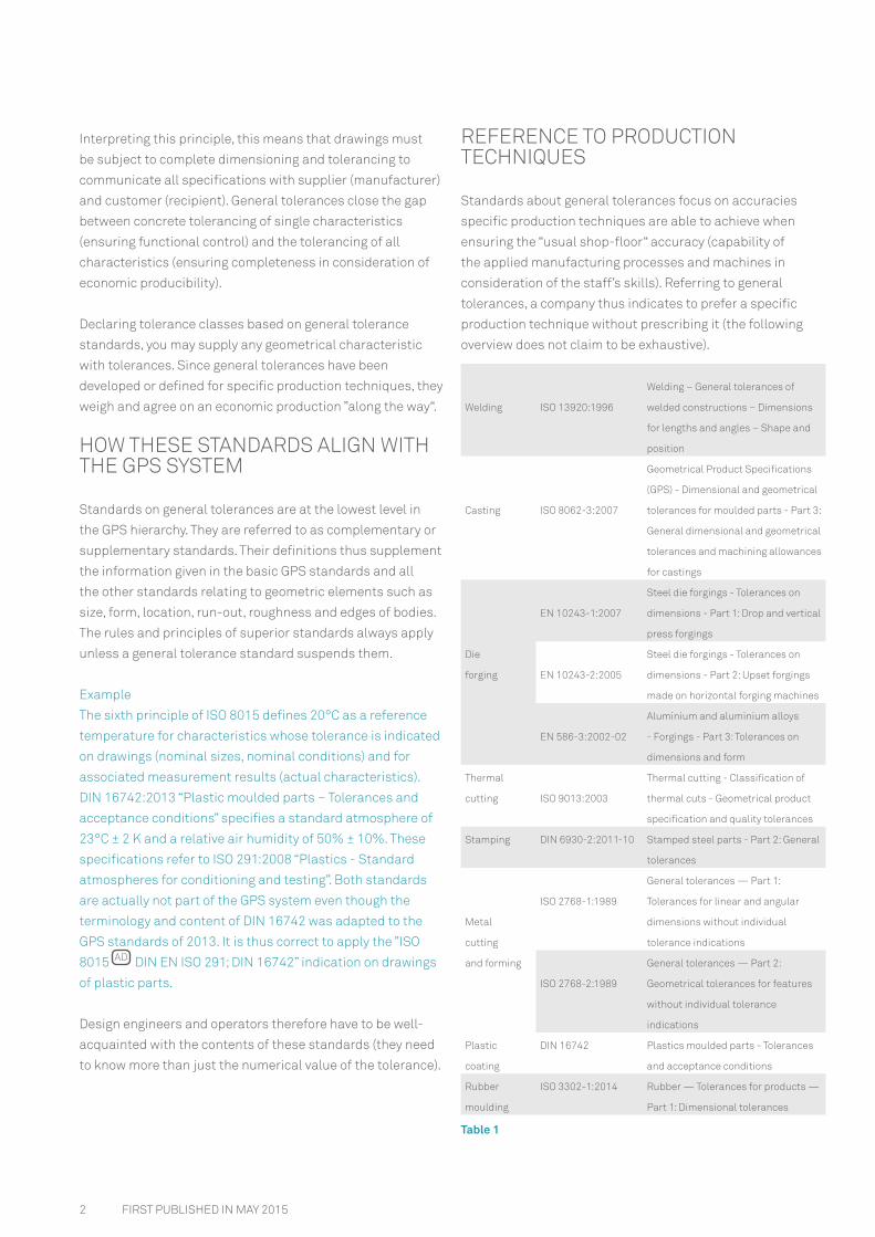
REFERENCE TO PRODUCTION TECHNIQUES
Standards about general tolerances focus on accuracies
specific production techniques are able to achieve when
ensuring the ldquousual shop-floorldquo accuracy (capability of
the applied manufacturing processes and machines in
consideration of the staffrsquos skills) Referring to general
tolerances a company thus indicates to prefer a specific
production technique without prescribing it (the following
overview does not claim to be exhaustive)
Welding ISO 139201996
Welding ndash General tolerances of
welded constructions ndash Dimensions
for lengths and angles ndash Shape and
position
Casting ISO 8062-32007
Geometrical Product Specifications
(GPS) - Dimensional and geometrical
tolerances for moulded parts - Part 3
General dimensional and geometrical
tolerances and machining allowances
for castings
Die
forging
EN 10243-12007
Steel die forgings - Tolerances on
dimensions - Part 1 Drop and vertical
press forgings
EN 10243-22005
Steel die forgings - Tolerances on
dimensions - Part 2 Upset forgings
made on horizontal forging machines
EN 586-32002-02
Aluminium and aluminium alloys
- Forgings - Part 3 Tolerances on
dimensions and form
Thermal
cutting ISO 90132003
Thermal cutting - Classification of
thermal cuts - Geometrical product
specification and quality tolerances
Stamping DIN 6930-22011-10 Stamped steel parts - Part 2 General
tolerances
Metal
cutting
and forming
ISO 2768-11989
General tolerances mdash Part 1
Tolerances for linear and angular
dimensions without individual
tolerance indications
ISO 2768-21989
General tolerances mdash Part 2
Geometrical tolerances for features
without individual tolerance
indications
Plastic
coating
DIN 16742 Plastics moulded parts - Tolerances
and acceptance conditions
Rubber
moulding
ISO 3302-12014 Rubber mdash Tolerances for products mdash
Part 1 Dimensional tolerances
Table 1
AD
3FIRST PUBLISHED IN MAY 2015
GPS - GENERAL TOLERANCES IN THE GPS CONCEPT
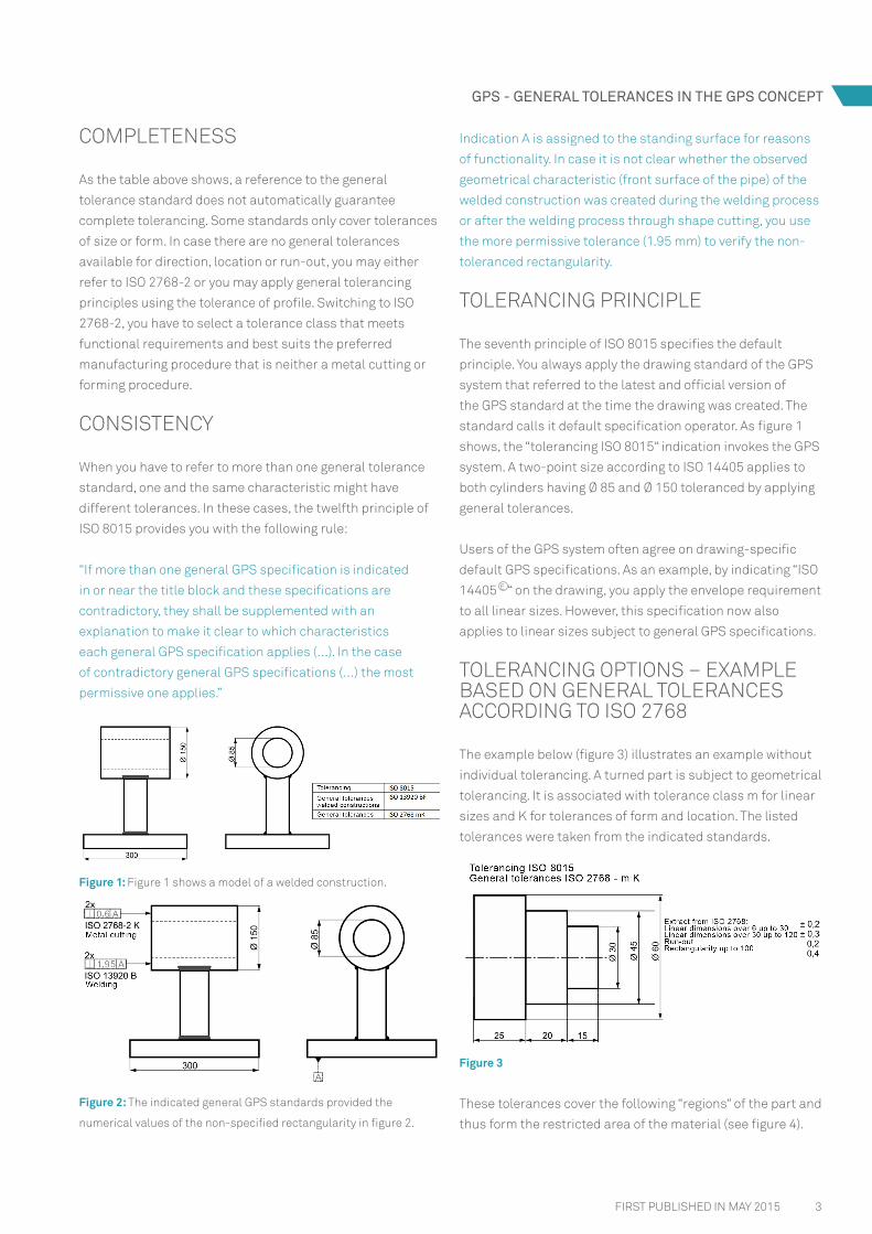
Indication A is assigned to the standing surface for reasons
of functionality In case it is not clear whether the observed
geometrical characteristic (front surface of the pipe) of the
welded construction was created during the welding process
or after the welding process through shape cutting you use
the more permissive tolerance (195 mm) to verify the non-
toleranced rectangularity
TOLERANCING PRINCIPLE
The seventh principle of ISO 8015 specifies the default
principle You always apply the drawing standard of the GPS
system that referred to the latest and official version of
the GPS standard at the time the drawing was created The
standard calls it default specification operator As figure 1
shows the ldquotolerancing ISO 8015ldquo indication invokes the GPS
system A two-point size according to ISO 14405 applies to
both cylinders having Oslash 85 and Oslash 150 toleranced by applying
general tolerances
Users of the GPS system often agree on drawing-specific
default GPS specifications As an example by indicating ldquoISO
14405 ldquo on the drawing you apply the envelope requirement
to all linear sizes However this specification now also
applies to linear sizes subject to general GPS specifications
TOLERANCING OPTIONS ndash EXAMPLE BASED ON GENERAL TOLERANCES ACCORDING TO ISO 2768
The example below (figure 3) illustrates an example without
individual tolerancing A turned part is subject to geometrical
tolerancing It is associated with tolerance class m for linear
sizes and K for tolerances of form and location The listed
tolerances were taken from the indicated standards
Figure 3
These tolerances cover the following ldquoregionsldquo of the part and
thus form the restricted area of the material (see figure 4)
COMPLETENESS
As the table above shows a reference to the general
tolerance standard does not automatically guarantee
complete tolerancing Some standards only cover tolerances
of size or form In case there are no general tolerances
available for direction location or run-out you may either
refer to ISO 2768-2 or you may apply general tolerancing
principles using the tolerance of profile Switching to ISO
2768-2 you have to select a tolerance class that meets
functional requirements and best suits the preferred
manufacturing procedure that is neither a metal cutting or
forming procedure
CONSISTENCY
When you have to refer to more than one general tolerance
standard one and the same characteristic might have
different tolerances In these cases the twelfth principle of
ISO 8015 provides you with the following rule
ldquoIf more than one general GPS specification is indicated
in or near the title block and these specifications are
contradictory they shall be supplemented with an
explanation to make it clear to which characteristics
each general GPS specification applies (hellip) In the case
of contradictory general GPS specifications (hellip) the most
permissive one appliesrdquo
Figure 1 Figure 1 shows a model of a welded construction
Figure 2 The indicated general GPS standards provided the
numerical values of the non-specified rectangularity in figure 2
E
4 FIRST PUBLISHED IN MAY 2015
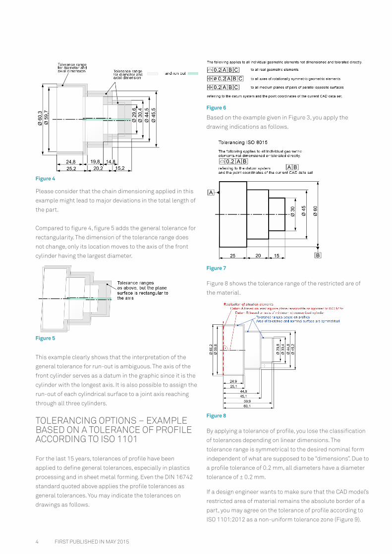
Figure 6
Based on the example given in Figure 3 you apply the
drawing indications as follows
Figure 7
Figure 8 shows the tolerance range of the restricted are of
the material
Figure 8
By applying a tolerance of profile you lose the classification
of tolerances depending on linear dimensions The
tolerance range is symmetrical to the desired nominal form
independent of what are supposed to be ldquodimensionsrdquo Due to
a profile tolerance of 02 mm all diameters have a diameter
tolerance of plusmn 02 mm
If a design engineer wants to make sure that the CAD modelrsquos
restricted area of material remains the absolute border of a
part you may agree on the tolerance of profile according to
ISO 11012012 as a non-uniform tolerance zone (Figure 9)
Figure 4
Please consider that the chain dimensioning applied in this
example might lead to major deviations in the total length of
the part
Compared to figure 4 figure 5 adds the general tolerance for
rectangularity The dimension of the tolerance range does
not change only its location moves to the axis of the front
cylinder having the largest diameter
Figure 5
This example clearly shows that the interpretation of the
general tolerance for run-out is ambiguous The axis of the
front cylinder serves as a datum in the graphic since it is the
cylinder with the longest axis It is also possible to assign the
run-out of each cylindrical surface to a joint axis reaching
through all three cylinders
TOLERANCING OPTIONS ndash EXAMPLE BASED ON A TOLERANCE OF PROFILE ACCORDING TO ISO 1101
For the last 15 years tolerances of profile have been
applied to define general tolerances especially in plastics
processing and in sheet metal forming Even the DIN 16742
standard quoted above applies the profile tolerances as
general tolerances You may indicate the tolerances on
drawings as follows
5FIRST PUBLISHED IN MAY 2015
GPS - GENERAL TOLERANCES IN THE GPS CONCEPT
NECESSITY TO CONTROL GENERALLY TOLERANCED CHARACTERISTICS ndash TOLERANCING ACCORDING TO ISO 2768
General tolerances shall simplify the design of parts based
on drawing indications Characteristics of form location and
orientation produced with the usual shop-floor accuracy are
toleranced based on a tolerance class specified in the above-
mentioned standards specific to the respective production
technique When you select the required tolerance class it is
important to consider the functional requirements primarily
You shall always have a look at the tolerance tables given in
the standards to see the symmetrical deviations for sizes
and tolerances referring to form and location These tables
help you define suitable or necessary tolerance classes
Tolerances smaller than the ones specified in the tables
shall always be indicated for the respective linear size or
geometric element on the drawing
It often happens that the title block of a drawing gives a
global agreement of typical tolerance classes by default
This agreement applies to an entire company or an entire
group and does not relate to the specific product shown
on the drawing at all You shall thus treat this information
with caution and check at least whether these global
specifications are acceptable for this very product or
whether comprehensive individual tolerancing is required
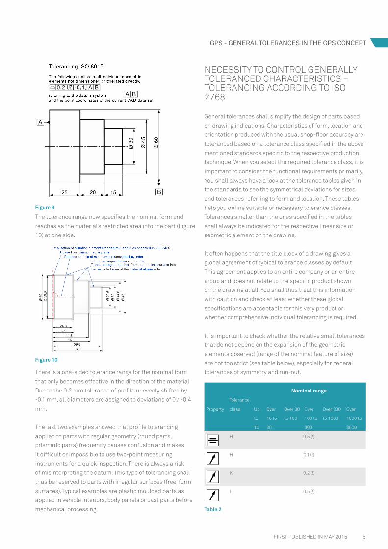
It is important to check whether the relative small tolerances
that do not depend on the expansion of the geometric
elements observed (range of the nominal feature of size)
are not too strict (see table below) especially for general
tolerances of symmetry and run-out
Property
Tolerance
class
Nominal range
Up
to
10
Over
10 to
30
Over 30
to 100
Over
100 to
300
Over 300
to 1000
Over
1000 to
3000
H 05 ()
H 01 ()
K 02 ()
L 05 ()
Table 2
Figure 9
The tolerance range now specifies the nominal form and
reaches as the materialrsquos restricted area into the part (Figure
10) at one side
Figure 10
There is a one-sided tolerance range for the nominal form
that only becomes effective in the direction of the material
Due to the 02 mm tolerance of profile unevenly shifted by
-01 mm all diameters are assigned to deviations of 0 -04
mm
The last two examples showed that profile tolerancing
applied to parts with regular geometry (round parts
prismatic parts) frequently causes confusion and makes
it difficult or impossible to use two-point measuring
instruments for a quick inspection There is always a risk
of misinterpreting the datum This type of tolerancing shall
thus be reserved to parts with irregular surfaces (free-form
surfaces) Typical examples are plastic moulded parts as
applied in vehicle interiors body panels or cast parts before
mechanical processing
6
bull Inspection planners and inspectors are to consider
constellations of geometric elements that are striking
or typical in their opinion (coaxialities between inside
and outside cylinders in case of cylindrical workpiece
symmetry constellations in case of prismatic workpieces)
It only applies to geometric elements that have not been
tolerated individually and these elements shall at least
be considered in initial sampling
NECESSITY TO CONTROL GENERALLY TOLERANCED CHARACTERISTICS ndash TOLERANCING ACCORDING TO DIN 16742 FOR PLASTIC MOULDED PARTS
The text in chapter 53 of this DIN standard gives a clear and
definitive statement about the necessity to control
Acceptance dimensions are all directly toleranced
characteristics All dimensions with general tolerances are
not considered in the test record
Chapter 56 adds
Free form surfaces shall be specified with a profile form
tolerance The verification shall be coordinated
NECESSITY TO CONTROL GENERALLY TOLERANCED CHARACTERISTICS ndash TOLERANCING BASED ON PROFILES ACCORDING TO ISO 1101
If profile tolerancing applies as a general tolerance
for irregular surfaces we will always assume that it is
impossible to give a definitive statement about the necessity
to control these characteristics This is due to vast number
of surface points toleranced like this However if this is your
intention all the same you will have to define the datum
system with clear datums for a reproducible comparison
with the nominal geometric data of the CAD model On
the other hand you have to use selected datums of the
generally toleranced surface as measuring points If all these
measuring points are within the demanded profile tolerance
zone we will assume that any other surface points will be
in the specification too It is not unusual to define selected
measuring points as special characteristics in order to agree
on the necessity to control such general tolerances
FIRST PUBLISHED IN MAY 2015
Independent of the selected tolerance class the annex of
ISO 2768-1 and of ISO 2768-2 specifies that the function of
a part often allows a geometrical tolerance larger than the
general tolerance values When the general tolerance of any
geometric element of the part is (occasionally) exceeded this
does not impair the function of the part
This is however a rather explosive statement since it implies
that generally toleranced geometrical characteristics are not
relevant to the function of a part and thus do not indicate
any necessity to be controlled However inspection planners
andor quality inspectors should not follow this statement
blindly but are supposed to use their technical knowledge At
least in the productprocess release phase (initial sampling)
you definitely have to control generally toleranced features of
size to prove that you keep the ldquousual shop-floorldquo accuracy
As opposed to features of size the necessity to control
generally toleranced characteristics of form and location
is considerably more difficult Since you do not have any
necessary symbols such as straightness evenness
rectangularity symmetry and coaxiality required for the
coding of functional requirements and since technical
drawings do not even indicate any clear datum there are
plenty of possible geometrical tolerances A simple cube as
shown below formally indicates the tolerances of form and
location according to ISO 2768-2
Geometric elements Geometric properties and tolerances
6 faces
6 tolerances of evenness
6 tolerances of parallelism (by switching datums)
24 tolerances of rectangularity (by switching
datums)
12 edges 12 tolerances of straightness
It is thus not possible to control these features not
even within the scope of initial sampling What are the
consequences
bull Design engineers shall indicate any tolerances of form
and location relevant to the function of the part by using
symbols and definitions based on ISO 1101 This leads
to a necessity to control characteristics at least within
the scope of initial sampling If these characteristics
are supposed to be special characteristics they need to
become part of production control plans or test plans
as characteristics that have to be controlled Design
engineers shall always cover their back and confirm the
part specification by referring to the general tolerances of
form and location (complete tolerancing)
GPS - GENERAL TOLERANCES IN THE GPS CONCEPT
Q-DAS GmbH
Eisleber Str 2
69469 Weinheim Germany
HexagonMIcom | q-dasde | teqde
guntereffenbergerq-dasde
HANDLING GENERAL TOLERANCES AT THE SUPPLIER-CUSTOMER (MANUFACTURER-CONSUMER) INTERFACE
Even though design engineers are glad to use general
tolerances to assist them with their work these general
tolerances however might turn out to be insidious in
quality assurance On the one hand this is due to the fact
that is often rather unclear whether these characteristics
need to be controlled On the other hand the known
standards on general tolerances specify that workpieces
with characteristics where the general tolerances are not
complied with may only be rejected (automatically) if the
function is impaired This is at least what ISO 2768 and DIN
16742 say almost verbatim and what ISO 13920 basically
means Independent of how an ldquoautomaticrdquo rejection works
in practice from a technical and organisational perspective
even a ldquousualrdquo complaint about such violations will prompt
the parties involved to give more or less detailed reasons
for this malfunction These parties might thus pass the
complaint back and forth
CONCLUSION
The GPS concept still supports the allocation of general
tolerances to geometrical characteristics based on
production techniques and thus offers the tolerancing
principles of ISO 1101 for free-form surfaces These
principles provide design engineers with reasonable tools
that have been tested for decades to ensure a complete
tolerancing concept based on best practice Expert groups
however frequently demand a drawing review to check
drawings for completeness unambiguity and GPS-compliant
specifications Staff reviewing a drawing shall have in-depth
knowledge of GPS standards and care for the application of
the latest rules and standards
The verification of generally toleranced characteristics is
however rather vague since the given complementary GPS
standards only consider a product that is defective since it
violates general tolerances to be a defect as to quality with
restrictions The rejection of such products is not always
permissible It is thus hard to define the necessity to control
these characteristics based on standards If you want to
clarify the situation nonetheless you shall add a quality
agreement to the supply agreement or indicate some further
specifications on the drawing
These considerations lead to the following conclusions
bull All characteristics controlling the function of a part have
to be dimensioned and tolerated directly to communicate
mandatory verification requirements
bull Design engineers shall always indicate general tolerances
for the reasons discussed in this article
bull When the supplier submits a quotation the supplier
shall focus on the feasibility (producibility) of the single
tolerated characteristics The next step is to assess
whether the usual shop-floor accuracy agrees with the
general tolerance class applied on the drawing
bull The quality agreement between manufacturer and
recipient may exclude the rejection paragraph of the
respective general tolerance standard or make it more
palpable
bull The agreement may even give more details about the
necessity to control generally toleranced characteristics
However we recommend you provide an indication
directly on the drawing
Interested in this topicInterested in this topic
2 FIRST PUBLISHED IN MAY 2015
Interpreting this principle this means that drawings must
be subject to complete dimensioning and tolerancing to
communicate all specifications with supplier (manufacturer)
and customer (recipient) General tolerances close the gap
between concrete tolerancing of single characteristics
(ensuring functional control) and the tolerancing of all
characteristics (ensuring completeness in consideration of
economic producibility)
Declaring tolerance classes based on general tolerance
standards you may supply any geometrical characteristic
with tolerances Since general tolerances have been
developed or defined for specific production techniques they
weigh and agree on an economic production rdquoalong the wayldquo
HOW THESE STANDARDS ALIGN WITH THE GPS SYSTEM
Standards on general tolerances are at the lowest level in
the GPS hierarchy They are referred to as complementary or
supplementary standards Their definitions thus supplement
the information given in the basic GPS standards and all
the other standards relating to geometric elements such as
size form location run-out roughness and edges of bodies
The rules and principles of superior standards always apply
unless a general tolerance standard suspends them
Example
The sixth principle of ISO 8015 defines 20degC as a reference
temperature for characteristics whose tolerance is indicated
on drawings (nominal sizes nominal conditions) and for
associated measurement results (actual characteristics)
DIN 167422013 ldquoPlastic moulded parts ndash Tolerances and
acceptance conditionsrdquo specifies a standard atmosphere of
23degC plusmn 2 K and a relative air humidity of 50 plusmn 10 These
specifications refer to ISO 2912008 ldquoPlastics - Standard
atmospheres for conditioning and testingrdquo Both standards
are actually not part of the GPS system even though the
terminology and content of DIN 16742 was adapted to the
GPS standards of 2013 It is thus correct to apply the rdquoISO
8015 DIN EN ISO 291 DIN 16742rdquo indication on drawings
of plastic parts
Design engineers and operators therefore have to be well-
acquainted with the contents of these standards (they need
to know more than just the numerical value of the tolerance)
REFERENCE TO PRODUCTION TECHNIQUES
Standards about general tolerances focus on accuracies
specific production techniques are able to achieve when
ensuring the ldquousual shop-floorldquo accuracy (capability of
the applied manufacturing processes and machines in
consideration of the staffrsquos skills) Referring to general
tolerances a company thus indicates to prefer a specific
production technique without prescribing it (the following
overview does not claim to be exhaustive)
Welding ISO 139201996
Welding ndash General tolerances of
welded constructions ndash Dimensions
for lengths and angles ndash Shape and
position
Casting ISO 8062-32007
Geometrical Product Specifications
(GPS) - Dimensional and geometrical
tolerances for moulded parts - Part 3
General dimensional and geometrical
tolerances and machining allowances
for castings
Die
forging
EN 10243-12007
Steel die forgings - Tolerances on
dimensions - Part 1 Drop and vertical
press forgings
EN 10243-22005
Steel die forgings - Tolerances on
dimensions - Part 2 Upset forgings
made on horizontal forging machines
EN 586-32002-02
Aluminium and aluminium alloys
- Forgings - Part 3 Tolerances on
dimensions and form
Thermal
cutting ISO 90132003
Thermal cutting - Classification of
thermal cuts - Geometrical product
specification and quality tolerances
Stamping DIN 6930-22011-10 Stamped steel parts - Part 2 General
tolerances
Metal
cutting
and forming
ISO 2768-11989
General tolerances mdash Part 1
Tolerances for linear and angular
dimensions without individual
tolerance indications
ISO 2768-21989
General tolerances mdash Part 2
Geometrical tolerances for features
without individual tolerance
indications
Plastic
coating
DIN 16742 Plastics moulded parts - Tolerances
and acceptance conditions
Rubber
moulding
ISO 3302-12014 Rubber mdash Tolerances for products mdash
Part 1 Dimensional tolerances
Table 1
AD
3FIRST PUBLISHED IN MAY 2015
GPS - GENERAL TOLERANCES IN THE GPS CONCEPT
Indication A is assigned to the standing surface for reasons
of functionality In case it is not clear whether the observed
geometrical characteristic (front surface of the pipe) of the
welded construction was created during the welding process
or after the welding process through shape cutting you use
the more permissive tolerance (195 mm) to verify the non-
toleranced rectangularity
TOLERANCING PRINCIPLE
The seventh principle of ISO 8015 specifies the default
principle You always apply the drawing standard of the GPS
system that referred to the latest and official version of
the GPS standard at the time the drawing was created The
standard calls it default specification operator As figure 1
shows the ldquotolerancing ISO 8015ldquo indication invokes the GPS
system A two-point size according to ISO 14405 applies to
both cylinders having Oslash 85 and Oslash 150 toleranced by applying
general tolerances
Users of the GPS system often agree on drawing-specific
default GPS specifications As an example by indicating ldquoISO
14405 ldquo on the drawing you apply the envelope requirement
to all linear sizes However this specification now also
applies to linear sizes subject to general GPS specifications
TOLERANCING OPTIONS ndash EXAMPLE BASED ON GENERAL TOLERANCES ACCORDING TO ISO 2768
The example below (figure 3) illustrates an example without
individual tolerancing A turned part is subject to geometrical
tolerancing It is associated with tolerance class m for linear
sizes and K for tolerances of form and location The listed
tolerances were taken from the indicated standards
Figure 3
These tolerances cover the following ldquoregionsldquo of the part and
thus form the restricted area of the material (see figure 4)
COMPLETENESS
As the table above shows a reference to the general
tolerance standard does not automatically guarantee
complete tolerancing Some standards only cover tolerances
of size or form In case there are no general tolerances
available for direction location or run-out you may either
refer to ISO 2768-2 or you may apply general tolerancing
principles using the tolerance of profile Switching to ISO
2768-2 you have to select a tolerance class that meets
functional requirements and best suits the preferred
manufacturing procedure that is neither a metal cutting or
forming procedure
CONSISTENCY
When you have to refer to more than one general tolerance
standard one and the same characteristic might have
different tolerances In these cases the twelfth principle of
ISO 8015 provides you with the following rule
ldquoIf more than one general GPS specification is indicated
in or near the title block and these specifications are
contradictory they shall be supplemented with an
explanation to make it clear to which characteristics
each general GPS specification applies (hellip) In the case
of contradictory general GPS specifications (hellip) the most
permissive one appliesrdquo
Figure 1 Figure 1 shows a model of a welded construction
Figure 2 The indicated general GPS standards provided the
numerical values of the non-specified rectangularity in figure 2
E
4 FIRST PUBLISHED IN MAY 2015
Figure 6
Based on the example given in Figure 3 you apply the
drawing indications as follows
Figure 7
Figure 8 shows the tolerance range of the restricted are of
the material
Figure 8
By applying a tolerance of profile you lose the classification
of tolerances depending on linear dimensions The
tolerance range is symmetrical to the desired nominal form
independent of what are supposed to be ldquodimensionsrdquo Due to
a profile tolerance of 02 mm all diameters have a diameter
tolerance of plusmn 02 mm
If a design engineer wants to make sure that the CAD modelrsquos
restricted area of material remains the absolute border of a
part you may agree on the tolerance of profile according to
ISO 11012012 as a non-uniform tolerance zone (Figure 9)
Figure 4
Please consider that the chain dimensioning applied in this
example might lead to major deviations in the total length of
the part
Compared to figure 4 figure 5 adds the general tolerance for
rectangularity The dimension of the tolerance range does
not change only its location moves to the axis of the front
cylinder having the largest diameter
Figure 5
This example clearly shows that the interpretation of the
general tolerance for run-out is ambiguous The axis of the
front cylinder serves as a datum in the graphic since it is the
cylinder with the longest axis It is also possible to assign the
run-out of each cylindrical surface to a joint axis reaching
through all three cylinders
TOLERANCING OPTIONS ndash EXAMPLE BASED ON A TOLERANCE OF PROFILE ACCORDING TO ISO 1101
For the last 15 years tolerances of profile have been
applied to define general tolerances especially in plastics
processing and in sheet metal forming Even the DIN 16742
standard quoted above applies the profile tolerances as
general tolerances You may indicate the tolerances on
drawings as follows
5FIRST PUBLISHED IN MAY 2015
GPS - GENERAL TOLERANCES IN THE GPS CONCEPT
NECESSITY TO CONTROL GENERALLY TOLERANCED CHARACTERISTICS ndash TOLERANCING ACCORDING TO ISO 2768
General tolerances shall simplify the design of parts based
on drawing indications Characteristics of form location and
orientation produced with the usual shop-floor accuracy are
toleranced based on a tolerance class specified in the above-
mentioned standards specific to the respective production
technique When you select the required tolerance class it is
important to consider the functional requirements primarily
You shall always have a look at the tolerance tables given in
the standards to see the symmetrical deviations for sizes
and tolerances referring to form and location These tables
help you define suitable or necessary tolerance classes
Tolerances smaller than the ones specified in the tables
shall always be indicated for the respective linear size or
geometric element on the drawing
It often happens that the title block of a drawing gives a
global agreement of typical tolerance classes by default
This agreement applies to an entire company or an entire
group and does not relate to the specific product shown
on the drawing at all You shall thus treat this information
with caution and check at least whether these global
specifications are acceptable for this very product or
whether comprehensive individual tolerancing is required
It is important to check whether the relative small tolerances
that do not depend on the expansion of the geometric
elements observed (range of the nominal feature of size)
are not too strict (see table below) especially for general
tolerances of symmetry and run-out
Property
Tolerance
class
Nominal range
Up
to
10
Over
10 to
30
Over 30
to 100
Over
100 to
300
Over 300
to 1000
Over
1000 to
3000
H 05 ()
H 01 ()
K 02 ()
L 05 ()
Table 2
Figure 9
The tolerance range now specifies the nominal form and
reaches as the materialrsquos restricted area into the part (Figure
10) at one side
Figure 10
There is a one-sided tolerance range for the nominal form
that only becomes effective in the direction of the material
Due to the 02 mm tolerance of profile unevenly shifted by
-01 mm all diameters are assigned to deviations of 0 -04
mm
The last two examples showed that profile tolerancing
applied to parts with regular geometry (round parts
prismatic parts) frequently causes confusion and makes
it difficult or impossible to use two-point measuring
instruments for a quick inspection There is always a risk
of misinterpreting the datum This type of tolerancing shall
thus be reserved to parts with irregular surfaces (free-form
surfaces) Typical examples are plastic moulded parts as
applied in vehicle interiors body panels or cast parts before
mechanical processing
6
bull Inspection planners and inspectors are to consider
constellations of geometric elements that are striking
or typical in their opinion (coaxialities between inside
and outside cylinders in case of cylindrical workpiece
symmetry constellations in case of prismatic workpieces)
It only applies to geometric elements that have not been
tolerated individually and these elements shall at least
be considered in initial sampling
NECESSITY TO CONTROL GENERALLY TOLERANCED CHARACTERISTICS ndash TOLERANCING ACCORDING TO DIN 16742 FOR PLASTIC MOULDED PARTS
The text in chapter 53 of this DIN standard gives a clear and
definitive statement about the necessity to control
Acceptance dimensions are all directly toleranced
characteristics All dimensions with general tolerances are
not considered in the test record
Chapter 56 adds
Free form surfaces shall be specified with a profile form
tolerance The verification shall be coordinated
NECESSITY TO CONTROL GENERALLY TOLERANCED CHARACTERISTICS ndash TOLERANCING BASED ON PROFILES ACCORDING TO ISO 1101
If profile tolerancing applies as a general tolerance
for irregular surfaces we will always assume that it is
impossible to give a definitive statement about the necessity
to control these characteristics This is due to vast number
of surface points toleranced like this However if this is your
intention all the same you will have to define the datum
system with clear datums for a reproducible comparison
with the nominal geometric data of the CAD model On
the other hand you have to use selected datums of the
generally toleranced surface as measuring points If all these
measuring points are within the demanded profile tolerance
zone we will assume that any other surface points will be
in the specification too It is not unusual to define selected
measuring points as special characteristics in order to agree
on the necessity to control such general tolerances
FIRST PUBLISHED IN MAY 2015
Independent of the selected tolerance class the annex of
ISO 2768-1 and of ISO 2768-2 specifies that the function of
a part often allows a geometrical tolerance larger than the
general tolerance values When the general tolerance of any
geometric element of the part is (occasionally) exceeded this
does not impair the function of the part
This is however a rather explosive statement since it implies
that generally toleranced geometrical characteristics are not
relevant to the function of a part and thus do not indicate
any necessity to be controlled However inspection planners
andor quality inspectors should not follow this statement
blindly but are supposed to use their technical knowledge At
least in the productprocess release phase (initial sampling)
you definitely have to control generally toleranced features of
size to prove that you keep the ldquousual shop-floorldquo accuracy
As opposed to features of size the necessity to control
generally toleranced characteristics of form and location
is considerably more difficult Since you do not have any
necessary symbols such as straightness evenness
rectangularity symmetry and coaxiality required for the
coding of functional requirements and since technical
drawings do not even indicate any clear datum there are
plenty of possible geometrical tolerances A simple cube as
shown below formally indicates the tolerances of form and
location according to ISO 2768-2
Geometric elements Geometric properties and tolerances
6 faces
6 tolerances of evenness
6 tolerances of parallelism (by switching datums)
24 tolerances of rectangularity (by switching
datums)
12 edges 12 tolerances of straightness
It is thus not possible to control these features not
even within the scope of initial sampling What are the
consequences
bull Design engineers shall indicate any tolerances of form
and location relevant to the function of the part by using
symbols and definitions based on ISO 1101 This leads
to a necessity to control characteristics at least within
the scope of initial sampling If these characteristics
are supposed to be special characteristics they need to
become part of production control plans or test plans
as characteristics that have to be controlled Design
engineers shall always cover their back and confirm the
part specification by referring to the general tolerances of
form and location (complete tolerancing)
GPS - GENERAL TOLERANCES IN THE GPS CONCEPT
Q-DAS GmbH
Eisleber Str 2
69469 Weinheim Germany
HexagonMIcom | q-dasde | teqde
guntereffenbergerq-dasde
HANDLING GENERAL TOLERANCES AT THE SUPPLIER-CUSTOMER (MANUFACTURER-CONSUMER) INTERFACE
Even though design engineers are glad to use general
tolerances to assist them with their work these general
tolerances however might turn out to be insidious in
quality assurance On the one hand this is due to the fact
that is often rather unclear whether these characteristics
need to be controlled On the other hand the known
standards on general tolerances specify that workpieces
with characteristics where the general tolerances are not
complied with may only be rejected (automatically) if the
function is impaired This is at least what ISO 2768 and DIN
16742 say almost verbatim and what ISO 13920 basically
means Independent of how an ldquoautomaticrdquo rejection works
in practice from a technical and organisational perspective
even a ldquousualrdquo complaint about such violations will prompt
the parties involved to give more or less detailed reasons
for this malfunction These parties might thus pass the
complaint back and forth
CONCLUSION
The GPS concept still supports the allocation of general
tolerances to geometrical characteristics based on
production techniques and thus offers the tolerancing
principles of ISO 1101 for free-form surfaces These
principles provide design engineers with reasonable tools
that have been tested for decades to ensure a complete
tolerancing concept based on best practice Expert groups
however frequently demand a drawing review to check
drawings for completeness unambiguity and GPS-compliant
specifications Staff reviewing a drawing shall have in-depth
knowledge of GPS standards and care for the application of
the latest rules and standards
The verification of generally toleranced characteristics is
however rather vague since the given complementary GPS
standards only consider a product that is defective since it
violates general tolerances to be a defect as to quality with
restrictions The rejection of such products is not always
permissible It is thus hard to define the necessity to control
these characteristics based on standards If you want to
clarify the situation nonetheless you shall add a quality
agreement to the supply agreement or indicate some further
specifications on the drawing
These considerations lead to the following conclusions
bull All characteristics controlling the function of a part have
to be dimensioned and tolerated directly to communicate
mandatory verification requirements
bull Design engineers shall always indicate general tolerances
for the reasons discussed in this article
bull When the supplier submits a quotation the supplier
shall focus on the feasibility (producibility) of the single
tolerated characteristics The next step is to assess
whether the usual shop-floor accuracy agrees with the
general tolerance class applied on the drawing
bull The quality agreement between manufacturer and
recipient may exclude the rejection paragraph of the
respective general tolerance standard or make it more
palpable
bull The agreement may even give more details about the
necessity to control generally toleranced characteristics
However we recommend you provide an indication
directly on the drawing
Interested in this topicInterested in this topic