geometric dimensioning & tolerancing
TRANSCRIPT

Technical Drawing Program
GEOMETRIC DIMENSIONING & TOLERANCING
The following terms and conditions are based on the ANSI Y14.5M - R1988
Standard and should serve as guides to good geometric dimensioning and
tolerancing techniques:
Geometric dimensioning and tolerance clarifies the dimensioning of parts in relation
to their assumed geometry, function and relationship to other parts.
Example: The top and bottom surfaces of a part are drawn are as two horizontal lines;
given one height dimension; and assumed to be parallel. The surfaces of the actual
part may or may not be parallel but may still be usable if given a geometric
dimensional tolerance.
The five (5) types of geometric tolerances are form, profile, orientation, location and
run out.
The four (4) characteristics of "Form" are straightness, flatness, circularity and
cylindricity.
The two (2) characteristics of "Profile" are profile of a line and profile of a surface.
The three (3) characteristics of "Orientation" are angularity, perpendicularity and
parallelism.
The three (3) characteristics of "Location" are true position, concentricity and
symmetry.
The two (2) characteristics of "Runout" are circular and total.

"Modifiers" are used to clarify the status of the material when a tolerance is applied. There are four (4) types of "Modifiers": maximum material condition, least material
condition, regardless of feature size and projected tolerance zone.
A "Feature Control Frame" is drawn as a rectangle .375" high and long enough to include a Geometric Dimensioning & Tolerance Symbol, a total tolerance value and a datum letter.
"Feature Control Frames" are attached to edges and surfaces by extension lines and to features by a leader.
"Datums" are edges, surfaces or features that are considered accurate for locating other features or surfaces.
"Datums" are labeled with a rectangle .375" high by .75" long that contains a letter preceeded by a dash (-) and followed by a dash (-).
"Datums" are attached to edges and surfaces by extension lines and to features by a leader.
NOTE: The American National Standard, ANSI Y14.5M, for the "Dimensioning and Tolerancing of Engineering Drawings and Related Documentation Practices" should be adhered to for uniformity and acceptance by other concerns. It must be remembered that there are no absolutely hard and fast rules, nor any practice, not subject to change or modification under special conditions or requirements of a particular industry. When there is a variation of any rule, there must always be a reason which can be completely justified.

Technology Education DepartmentTechnical Drawing Program
ABBREVIATIONS & SYMBOLSR - radius - distance from center to edge of circle or arcØ - diameter - distance from edge to edge of circle through the centerTYP - typical - when same values or sizes are used in other locations on a drawingREF - reference - used to indicate a general measurement for checking overall size, noncritical measurements- centerline - to indicate the center locatioon of symetrical shapes
- depth - to indicate how deep a hole is drilled- counter-bore - used to create over-sized hole to recess the head of a screw or bolt- counter-sink - used to taper the top portion of a hole to accept a flathead screw- spot-face - used to create a smooth surface at the top of a hole, usually very shallow in depthFAO - finished all over - all surfaces have been machined, sanded, buffed or polishedCI - cast iron - material used to make parts cast in molds in a foundryCRS - cold rolled steel - type of steel sheet made by passing steel through rollersAL - aluminum - soft, light weight, easily worked metalUNC - Unified National Course - classification of screw threadsUNF - Unified National Fine - classification of screw threadsUNEF - Unified National Extra Fine - classification of screw threadsANSI - American National Standards Institute - governmental organization that establishes uniform procedures and practices for design, engineering and draftingISO - International Standards Organization - international body that establishes uniform procedures and practices for design, engineering and draftingSI - Systems International - metric system of measurementsBOCA - Building Officials Congress of America - governmental organization that establishes minimum construction procedures and practices for design, engineering and building of structuresCAD - Computer Aided Design - software used by engineers and architects to create three dimensional models of products and structures on a computerCADD - Computer Assisted Drafting & Design - software used by engineers and architects to create two and three dimensional drawings of products and structures on a computer
Technical Drawing ProgramTypes of Pictorial Views
AXONOMETRICS - ISOMETRIC - DIMETRIC - TRIMETRIC
Isometric pictorial views are the easiest to draw as the three axis for length, width and height are equally spaced at 120° apart and can be measured at actual size. A single isometric ellipse template is used to draw ellipses on any of the three surfaces.
Dimetric pictorial views emphasize two surfaces that use two axis at equal angles such as 110° and 110° and distort the third surface which would be at 140° or any combination in which two of the axis are equal (105-105-150) (115-115-130) but more than 90°. Actual size measurements can be made on the vertical axis but a reduced scale (3/4 size) must be used on the length and width axis. One angle size ellipse template is used to draw ellipses on the front and right-side surfaces and a second angle size ellipse template is used to draw ellipses on the top surface.
Trimetric pictorial views emphasize one surface that uses an angle such as 100° and distort the other surfaces at 125° and 135° or any combination in which all three are different (105-120-135) (110-120-130) but more than 90°. Actual size measurements can be made on the vertical axis but a reduced scale (3/4 size) must be used on the length axis and another reduced scale (1/2 size) must be used on thewidth axis. One angle size ellipse template is used to draw ellipses on the front surface, a second angle size ellipse template is used to draw ellipses on the right-side surface, and a third angle size ellipse template is used to draw ellipses on the top surface.
OBLIQUES - CABINET & CAVALIERCabinet oblique pictorial views are commonly used for drawing furniture or cylindrical shaped objects that do not have a lot of detail on the top or right-side surfaces. The height

and length axis are at a 90° angle and the width axis is usually at 45° to horizontal. Height and length dimensions are actual size but the width dimension is divided in half. A circle template is used to draw circles and arcs on the front surface and an angle-sized ellipse template is used to draw ellipses on the right-side and top surfaces.Cavalier oblique pictorial views are commonly used for drawing thin objects that do not have a lot of width. The height and length axis are at a 90° angle and the width axis is usually at 45° to horizontal. Height, width and length dimensions are actual size. A circle template is used to draw circles and arcs on the front surface and an angle-sized ellipse template is used to draw ellipses on the right-side and top surfaces.
PERSPECTIVES - ONE POINT - TWO POINTS - THREE POINTSPerspective views are used when a more realistic appearance is needed. The number of "points" refers to the "vanishing points" that are needed to make the object appear smaller as the eye moves from the front surface or a corner toward the back of the object. These views are more difficult to draw as measurements are made in one view and projected to the "vanishing points".One point perspective views are used for simple objects or for doing room interior views.Two point perspective views are used for buildings and houses usually showing the front and a side.Three point perspective views are used for very tall structures.ALPHABET OF LINESThe "Alphabet of Lines" is a list of line symbols that are used on technical drawings to represent the shape and describe the size of an object. Each of the following lines is drawn at different thickness or darkness for contrast as well as according to the importance of the line. If two lines fall on top of one another (coinside), the more important line is shown. Visible lines take presidence over hidden lines and center lines; and hidden lines take presidence over center lines. The list below gives the name of the line; explains how the line is used; indicates the appropriate thickness or darkness; and provides the recommended pencil weight for drawing the line.

Technical Drawing ProgramPRECISION DIMENSIONINGGeneral dimensioning rules and techniques are necessary for uniformity and clarity on Detail Drawings. Products or parts of products that must fit together or move within each other must be dimensioned more precisely using tolerances. The following terms and conditions are based on the ANSI B4.1 - 1967, R1987 Standard Fit Tables in Appendix B of your textbook and should serve as guides to good precision dimensioning techniques:
The size of a part can be expressed in three ways: nominal size, design size or actual size.

Nominal size is used to refer to the descriptive size of the part.Example: A 1"Ø steel rod that is actually .995"Ø or a 2" x 4" wooden stud that is actually 1.5" x 3.5".
Design size is used to describe the optimum or ideal size of the part or parts before tolerances are applied.Example: A 2"Ø hole is to be drilled in a wheel for a 2"Ø axle with a loose fit. The hole would actually be dimensioned as 2.000" +/-.001" and the axle would be dimensioned as 1.995" +/-.001" for a clearance of .003" and an allowance of .007".
Actual size is used to describe the measured size of the part or parts after they are produced. The hole in the wheel described above could be anywhere between 1.999" to 2.001" (maybe 1.9995") and the axle could be anywhere between 1.994" to 1.996" (maybe 1.9955").
A tolerance is the total amount of variation in the size of a part or feature on a part. To find the tolerance of a part or feature substract the smallest size from the largest size.Example: Given a dimension of 2.50 +/- .05 - the largest size would be 2.55, the smallest size would be 2.45, and the tolerance would be .10.
A bilateral tolerance is the amount of variation above or below the design size.Example: 3.75 +/-.05 which means the feature or parts can be as small as 3.70 or as large as 3.80.
A unilateral tolerance is the amount of variation in one direction either above or below the design size.Example: 3.75 +.05/-.00 which means the feature or parts can be as small as 3.75 or as large as 3.80.
Tolerance dimensions can be express as plus or minus (+/-) values or as limits (largest size over smallest size) values.Example: 10.50 +/- .05 or 10.55 / 10.45.
Different tolerances or limits can be specified for each of the three types of dimensions:overall length, width and height limit dimensions might have a tolerance of +/- .05specific size limit dimensions of features might have a tolerance of +/- .025locational limit dimensions might have a tolerance of +/- .0125
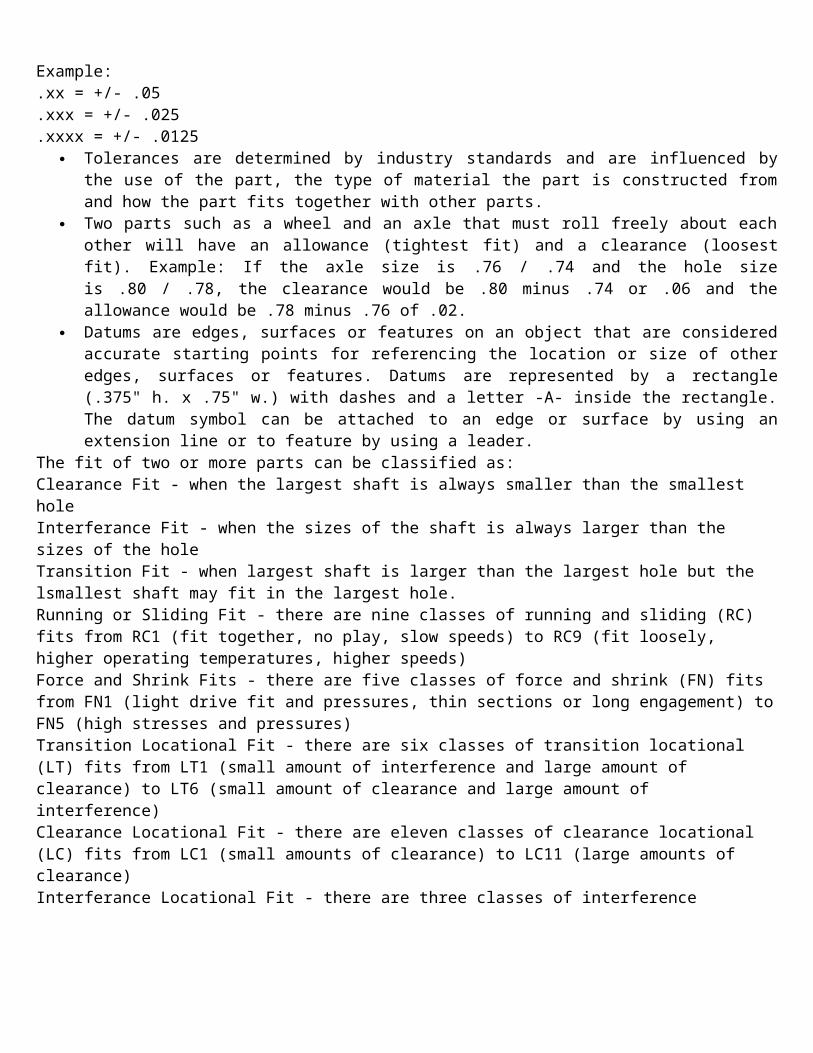
Generall tolerances can be specified on a drawing as a note using the number of decimal places to indicate the degree of accuracy. Example: .xx = +/- .05.xxx = +/- .025.xxxx = +/- .0125
Tolerances are determined by industry standards and are influenced by the use of the part, the type of material the part is constructed from and how the part fits together with other parts.
Two parts such as a wheel and an axle that must roll freely about each other will have an allowance (tightest fit) and a clearance (loosest fit). Example: If the axle size is .76 / .74 and the hole size is .80 / .78, the clearance would be .80 minus .74 or .06 and the allowance would be .78 minus .76 of .02.
Datums are edges, surfaces or features on an object that are considered accurate starting points for referencing the location or size of other edges, surfaces or features.

Datums are represented by a rectangle (.375" h. x .75" w.) with dashes and a letter -A- inside the rectangle. The datum symbol can be attached to an edge or surface by using an extension line or to feature by using a leader.
The fit of two or more parts can be classified as: Clearance Fit - when the largest shaft is always smaller than the smallest holeInterferance Fit - when the sizes of the shaft is always larger than the sizes of the holeTransition Fit - when largest shaft is larger than the largest hole but the lsmallest shaft may fit in the largest hole.Running or Sliding Fit - there are nine classes of running and sliding (RC) fits from RC1 (fit together, no play, slow speeds) to RC9 (fit loosely, higher operating temperatures, higher speeds)Force and Shrink Fits - there are five classes of force and shrink (FN) fits from FN1 (light drive fit and pressures, thin sections or long engagement) to FN5 (high stresses and pressures) Transition Locational Fit - there are six classes of transition locational (LT) fits from LT1 (small amount of interference and large amount of clearance) to LT6 (small amount of clearance and large amount of interference)Clearance Locational Fit - there are eleven classes of clearance locational (LC) fits from LC1 (small amounts of clearance) to LC11 (large amounts of clearance) Interferance Locational Fit - there are three classes of interference locational (LN) fits from LN1 (small amounts of intereference) to LN3 (large amounts of intereference)
Least Material Condition - when the least material is available on the part (lower limit for a shaft or higher limit for a hole)
Maximum Material Condition - when the most material is available on the part (higher limit for a shaft or lower limit for a hole)
Basic Hole System - Tolerances are applied to a hole and a shaft using the nominal size of the hole as a starting point
Basic Shaft Systems - Tolerances are applied to the shaft and hole using the nominal size of the shaft as a starting point
NOTE: The American National Standard, ANSI Y14.5M, for the "Dimensioning and Tolerancing of Engineering Drawings and Related Documentation Practices" should be adhered to for uniformity and acceptance by other concerns. It must be remembered that there are no absolutely hard and fast rules, nor any practice, not subject to change or modification under special conditions or requirements of a particular industry. When there is a variation of any rule, there must always be a reason which can be completely justified.

THREAD SPECIFICATIONSFasteners such as screws, bolts and nuts have threads that allow two objects to be assembled and disassembled. The size of the threads are indicated on a drawing using a leader and a note or "CALL OFF". The thread specification contains:INCH SYSTEM
the nominal diameter of the fastener the number of threads per inch - TPI the thread Series - UNC (Unified National Course), UNF (Unified National Fine) or UNEF
(Unified National Extra Fine) the class of Fit - 1 (loose), 2 (average) or 3 (tight) the type of thread - A (external) or B (internal) the length of the fastener
EXAMPLE: .5 - 13 UNC - 2 A x 3METRIC SYSTEM
the letter M - to denote metric system the diameter in millimetre the Pitch in millimetre - distance between crest of threads the thread tolerance (class of Fit) 1. (free) 5H, internal & 4g, external 2. (medium) 6H, internal & 6g, external 3. (tight) 7H, internal & 8g, external
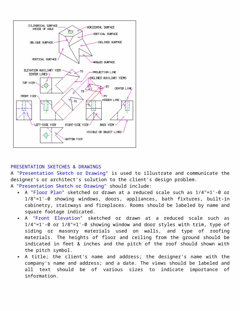
PRINCIPAL (NORMAL) VIEWS & TERMINOLOGYThe Isometric View shown below is of a Single Object. Study the Views carefully and then move to the bottom of this page to see a Multiview Drawing that includes Auxiliary Views.

PRESENTATION SKETCHES & DRAWINGSA "Presentation Sketch or Drawing" is used to illustrate and communicate the designer's or architect's solution to the client's design problem.A "Presentation Sketch or Drawing" should include:
A "Floor Plan" sketched or drawn at a reduced scale such as 1/4"=1'-0 or 1/8"=1'-0 showing windows, doors, appliances, bath fixtures, built-in cabinetry, stairways and fireplaces. Rooms should be labeled by name and square footage indicated.
A "Front Elevation" sketched or drawn at a reduced scale such as 1/4"=1'-0 or 1/8"=1'-0 showing window and door styles with trim, type of siding or masonry materials used on walls, and type of roofing materials. The heights of floor and ceiling from the ground should be indicated in feet & inches and the pitch of the roof should shown with the pitch symbol.
A title; the client's name and address; the designer's name with the company's name and address; and a date. The views should be labeled and all text should be of various sizes to indicate importance of information.
Optional perspective or other pictorial views, sectional views, interior views, plot plans, landscape plans and/or furniture plans may also be included on Presentation Sketches or Drawings.
"Presentation Sketches or Drawings" are usually prepared on illustration board, vellum, sketching or bond papers.
Hatching, shading and rendering techniques along with colored pencils, inks or markers may also be used to portray a more realistic appearance.

HOLESHoles are placed in objects for a variety of reasons.
To see through an object. To make an object lighter in weight. To place other objects into or through an object. To join two or more objects with a screw or a bolt and nut.
TYPES OF HOLES
LABELING HOLESHoles are labeled using notes and leaders. Each type of hole requires different information.DRILLED HOLE - Ø.75 THRU, # OF HOLESBLIND HOLE - Ø.75 X .5 DEEP, # OF HOLESCOUNTER BORED HOLE - Ø1.0 CBORE x .25 DEEP, Ø.75 THRU, # OF HOLESCOUNTER SUNK HOLE - Ø1.0 x 90° CKS, Ø.75 THRU, # OF HOLESSPOT FACED HOLE - Ø1.25 SPF X .125 DEEP, Ø.75 THRU, # OF HOLESTHREADED HOLE - Ø.5 X 20 UNC - 2B, , # OF HOLES
Technical Drawing ProgramGEOMETRIC CONSTRUCTIONSGeometric constructions allow the architect, engineer, designer or drafter to apply the principles of geometry in the creation of accurate drawings of objects using only a compass to draw arcs and a straight-edge to draw lines.
Bisect a line - locates the midpoint of a line and creates a perpendicular line at the midpoint of the line.
Given Line AB, draw two arcs (red) AC & BD (AC=BD) and then draw a line (blue) at the points of intersection E & F.
Bisect an arc - locates the midpoint of an arc and creates a line that passes through the center of the arc.
Given Arc AB, draw two arcs (red) AC & BD (AC=BD) and then draw a line (blue) at the points of intersection.
Bisect an angle - divides an angle into two equal angles and can be used to create 45° angled lines.
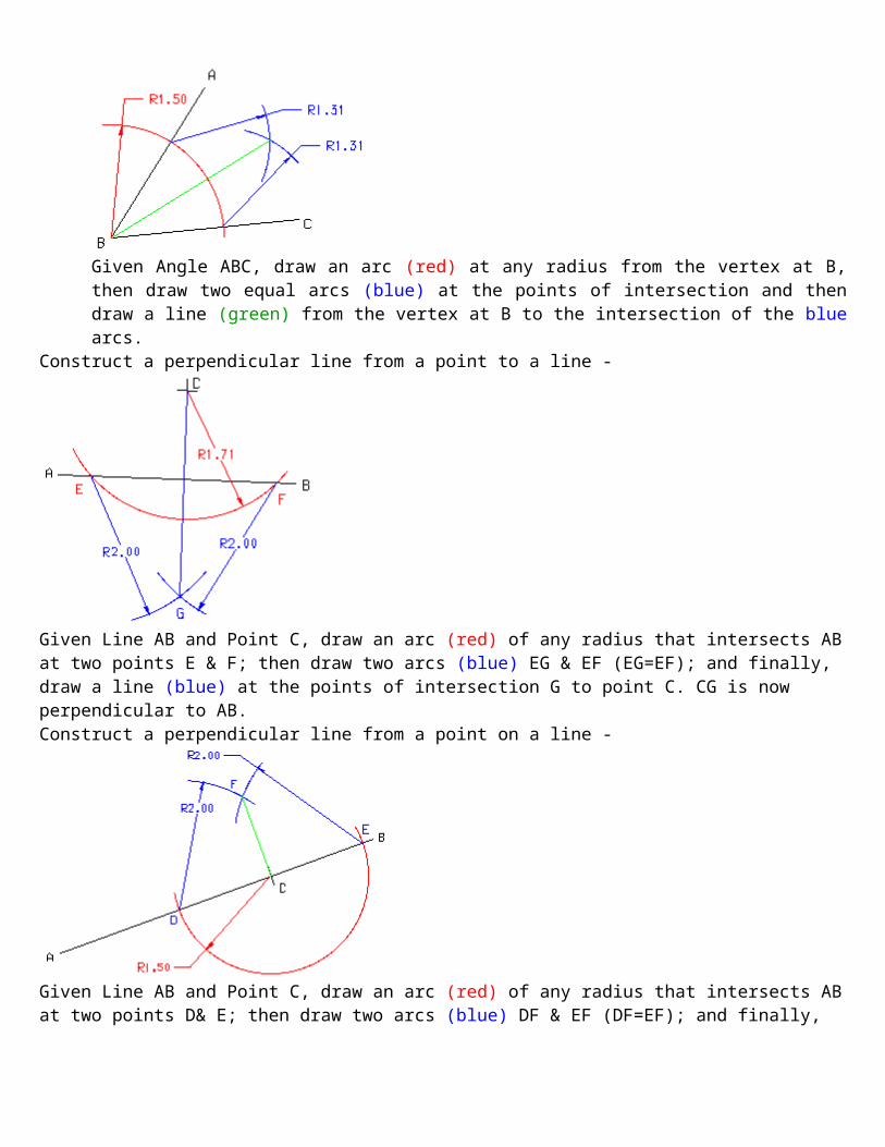
Given Angle ABC, draw an arc (red) at any radius from the vertex at B, then draw two equal arcs (blue) at the points of intersection and then draw a line (green) from the vertex at B to the intersection of the blue arcs.

Construct a perpendicular line from a point to a line -
Given Line AB and Point C, draw an arc (red) of any radius that intersects AB at two points E & F; then draw two arcs (blue) EG & EF (EG=EF); and finally, draw a line (blue) at the points of intersection G to point C. CG is now perpendicular to AB.Construct a perpendicular line from a point on a line -
Given Line AB and Point C, draw an arc (red) of any radius that intersects AB at two points D& E; then draw two arcs (blue) DF & EF (DF=EF); and finally, draw a line (blue) at the point of intersection F to point C. CF is now perpendicular to AB.

Construct a perpendicular line from a point near the end of a line -
Given Line AB and Point C, draw an arc (red) of any radius that intersects AB at points C & D; then draw a line (blue) from point D throught the center of the (red) arc until it intersects the arc again at E; then draw a line (green) at the points of intersection E to point C. CE is now perpendicular to AB.Construct a line parallel to a line from a point -
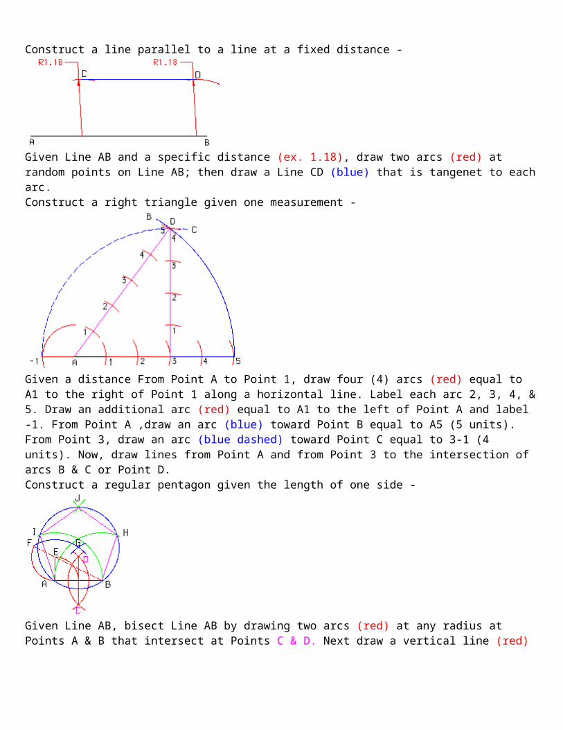
Given Line AB and Point C, draw an arc from Point C at any radius (2.41) intersecting Line AB at Point D. Repeat the (2.41) radius from Point D interssecting AB at Point E. At Ponit E draw a radius from Point C (1,18) and repeat the (1.18) at Point D intersecting the (2.41) radius at Point F. Now, draw a line from Point C to Point F.Construct a line parallel to a line at a fixed distance -
Given Line AB and a specific distance (ex. 1.18), draw two arcs (red) at random points on Line AB; then draw a Line CD (blue) that is tangenet to each arc.

Construct a right triangle given one measurement -
Given a distance From Point A to Point 1, draw four (4) arcs (red) equal to A1 to the right of Point 1 along a horizontal line. Label each arc 2, 3, 4, & 5. Draw an additional arc (red) equal to A1 to the left of Point A and label -1. From Point A ,draw an arc (blue) toward Point B equal to A5 (5 units). From Point 3, draw an arc (blue dashed) toward Point C equal to 3-1 (4 units). Now, draw lines from Point A and from Point 3 to the intersection of arcs B & C or Point D.Construct a regular pentagon given the length of one side -
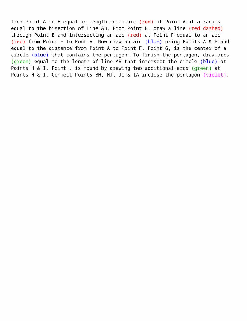
Given Line AB, bisect Line AB by drawing two arcs (red) at any radius at Points A & B that intersect at Points C & D. Next draw a vertical line (red) from Point A to E equal in length to an arc (red) at Point A at a radius equal to the bisection of Line AB. From Point B, draw a line (red dashed) through Point E and intersecting an arc (red) at Point F equal to an arc (red) from Point E to Pont A. Now draw an arc (blue) using Points A & B and equal to the distance from Point A to Point F. Point G, is the center of a circle (blue) that contains the pentagon. To finish the pentagon, draw arcs (green) equal to the length of line AB that intersect the circle (blue) at Points H & I. Point J is found by drawing two additional arcs (green) at Points H & I. Connect Points BH, HJ, JI & IA inclose the pentagon (violet).

Inscribe a regular pentagon within a given circle -
Given Center Lines AB & CD, draw a circle of any radius and bisect the radial center line from the center of the circle to the edge of the circle to find the the mid-point I using TWO equal (red) Arcs EF& HG and a (red) perpendicular line from EH to FG. Next draw an Arc (blue) from Point J where the vertical center line CD intersects the circle to Point K on center line AB with a radius from Point I to Point J. Next draw an Arc (green) from Point K on the horizontal center line AB to the circle Point L with a radius from Point J to Point K. This radius can be marked on the opposite side of the circle Point P and then copied at Points M & N. The distance between Points M & N should be the same as the distances between Points J & L, L & M, J & P, P & N. Construct a regular hexagon within a given circle -
Given two Center Lines and a Circle of any diameter, draw TWO Arcs (red) at Points A & D that intersect the Circle at Points C & B and E & F. Now draw straight lines (blue) from A to C, C to E, E to D, D to F, F to B and B to A to complete the hexagon.
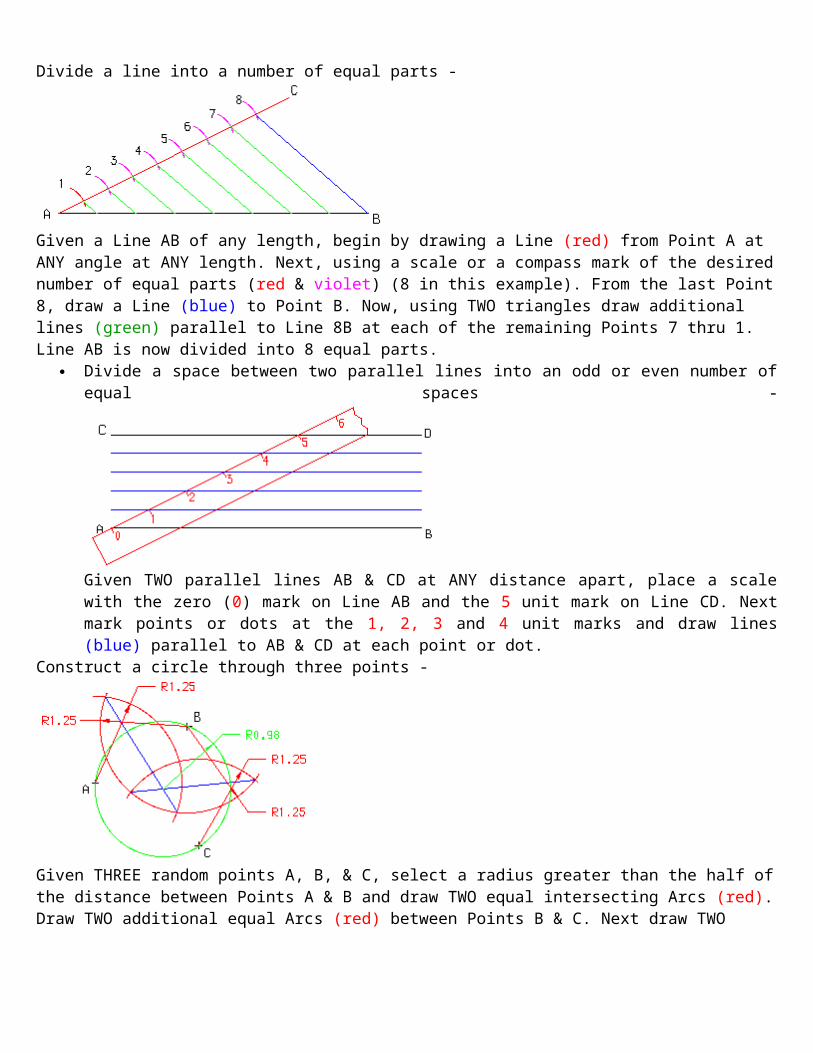
Divide a line into a number of equal parts -
Given a Line AB of any length, begin by drawing a Line (red) from Point A at ANY angle at ANY length. Next, using a scale or a compass mark of the desired number of equal parts (red & violet) (8 in this example). From the last Point 8, draw a Line (blue) to Point B. Now, using TWO triangles draw additional lines (green) parallel to Line 8B at each of the remaining Points 7 thru 1. Line AB is now divided into 8 equal parts.
Divide a space between two parallel lines into an odd or even number of equal spaces -
Given TWO parallel lines AB & CD at ANY distance apart, place a scale with the zero (0) mark on Line AB and the 5 unit mark on Line CD. Next mark points or dots at the 1, 2, 3 and 4 unit marks and draw lines (blue) parallel to AB & CD at each point or dot.
Construct a circle through three points -
Given THREE random points A, B, & C, select a radius greater than the half of the distance between Points A & B and draw TWO equal intersecting Arcs (red). Draw TWO additional equal Arcs (red) between Points B & C. Next draw TWO straight lines (blue) through the intersections of the arcs. Finally, draw a Circle (green) with the center at the intersection of the TWO (blue) lines and the radius equal to the distance to A, B or C. ALL Points should be on the (green) circle.

Find the center of a circle -
Given a Circle of any diameter, draw TWO straight line (red) that intersect the circumference of the circle at Points A, B & C. Next bisect line AB (red) using TWO Arcs (blue) and a strainght line DE (green). THEN bisect line BC (red) using TWO Arcs (blue) and a strainght line GF (green). The Point H of intersection of the TWO (green) lines is the center of the circle.
Create an ogee curve - connects two parallel lines with a curve that changes direction
Given two parallel lines AB and CD, draw a line (red) connecting the end of Line Ab at point B and the end of Line CD at point C. Next bisect Line BC (red) using two equal arcs (red) EF and GH. Then draw a straight line (blue) through the intersections of the arcs to find the midpoint of Line BC. Now, bisect each half of Line BC using Arcs KL & IJ as well as Arcs MN & OP and draw additional Lines (blue) at the points of intersection. Next, draw perpendicular lines (green) at Points B & C. The points of intersection between the (Green) Lines and the 2nd & 3rd (Blue) lines are the center points for the Arcs (violet) that begin at Points B & c and meet at the midpoint of Line BC.
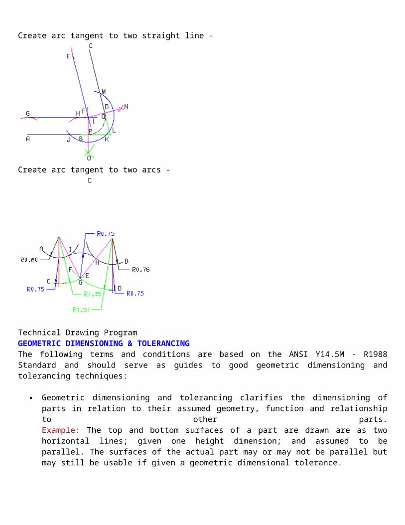
Create arc tangent to two straight line -
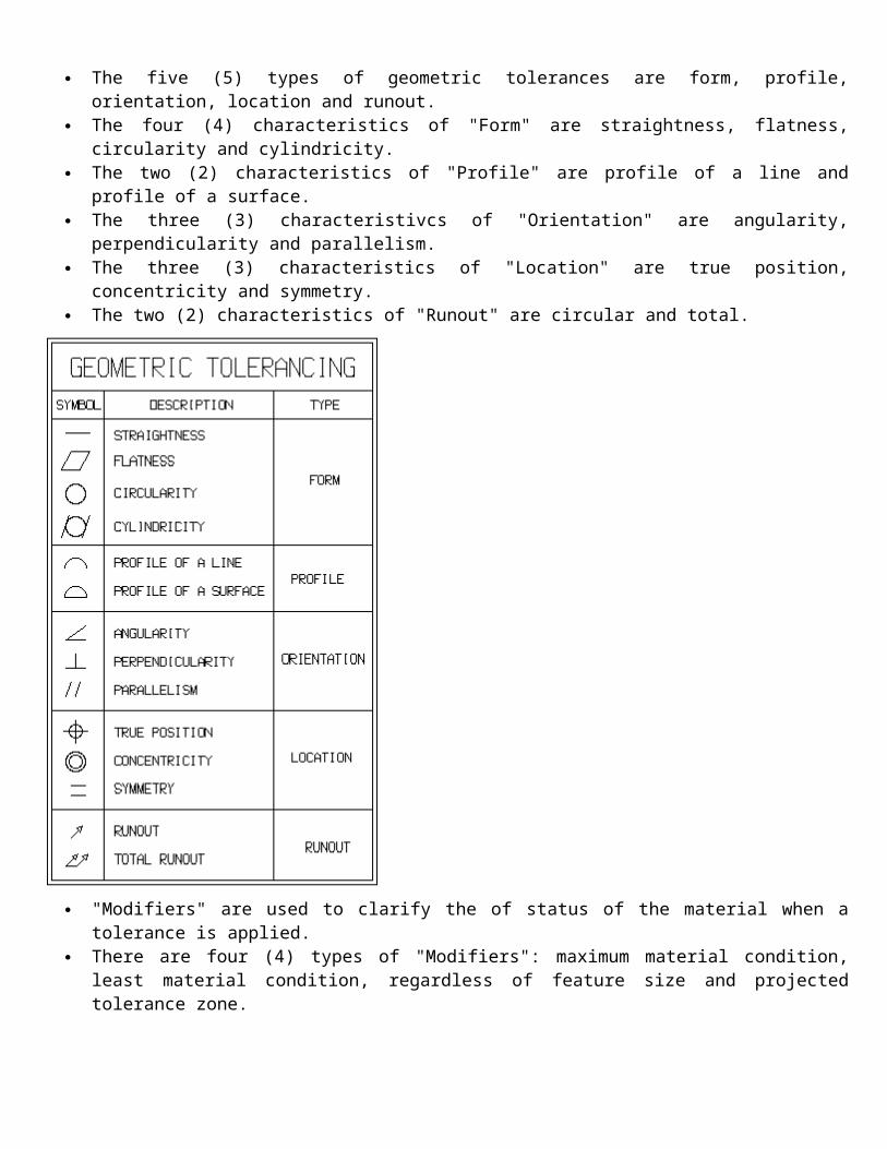
Create arc tangent to two arcs -
Technical Drawing ProgramGEOMETRIC DIMENSIONING & TOLERANCINGThe following terms and conditions are based on the ANSI Y14.5M - R1988 Standard and should serve as guides to good geometric dimensioning and tolerancing techniques:
Geometric dimensioning and tolerancing clarifies the dimensioning of parts in relation to their assumed geometry, function and relationship to other parts.Example: The top and bottom surfaces of a part are drawn are as two horizontal lines; given one height dimension; and assumed to be parallel. The surfaces of the actual part may or may not be parallel but may still be usable if given a geometric dimensional tolerance.
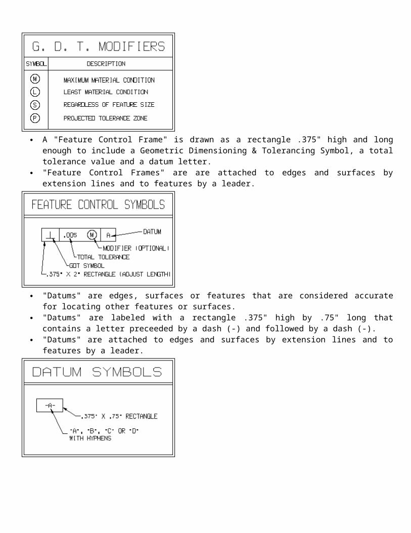
The five (5) types of geometric tolerances are form, profile, orientation, location and runout.
The four (4) characteristics of "Form" are straightness, flatness, circularity and cylindricity.
The two (2) characteristics of "Profile" are profile of a line and profile of a surface.
The three (3) characteristivcs of "Orientation" are angularity, perpendicularity and parallelism.
The three (3) characteristics of "Location" are true position, concentricity and symmetry.
The two (2) characteristics of "Runout" are circular and total.
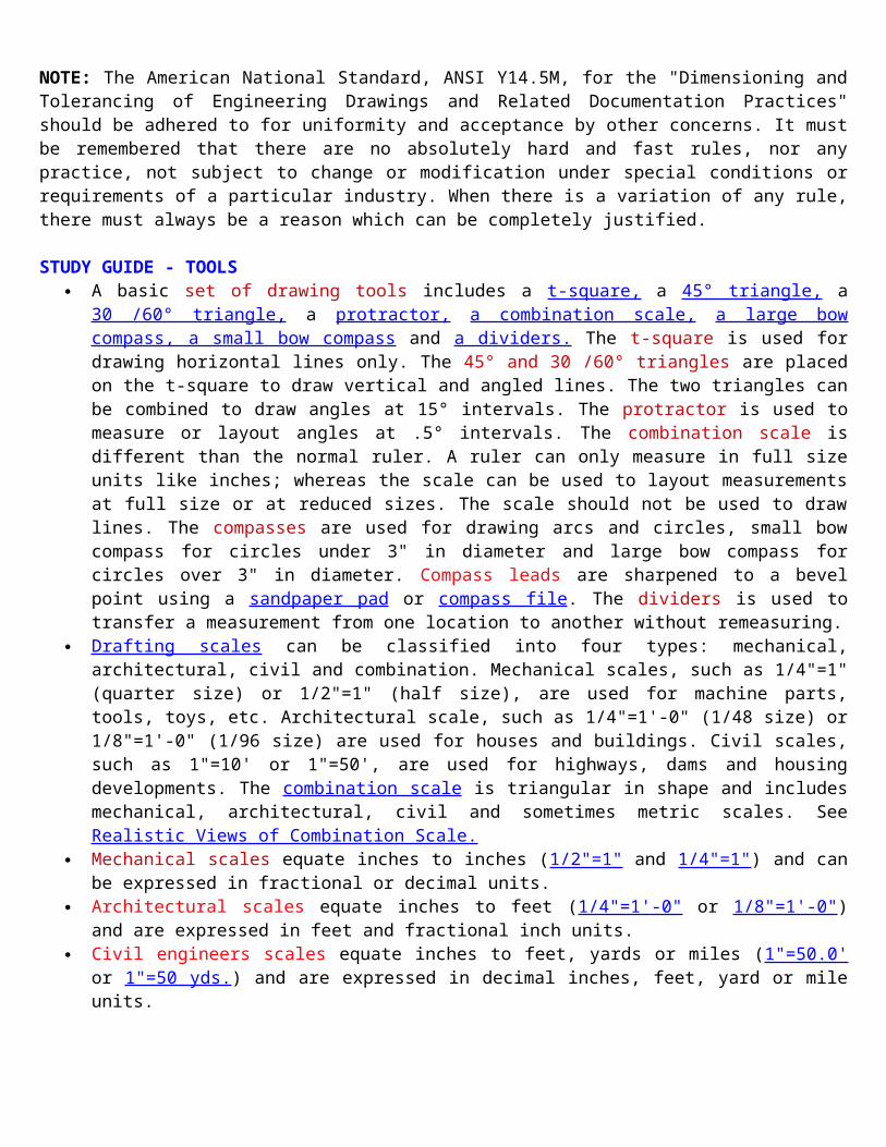
"Modifiers" are used to clarify the of status of the material when a tolerance is applied.
There are four (4) types of "Modifiers": maximum material condition, least material condition, regardless of feature size and projected tolerance zone.

A "Feature Control Frame" is drawn as a rectangle .375" high and long enough to include a Geometric Dimensioning & Tolerancing Symbol, a total tolerance value and a datum letter.
"Feature Control Frames" are are attached to edges and surfaces by extension lines and to features by a leader.
"Datums" are edges, surfaces or features that are considered accurate for locating other features or surfaces.
"Datums" are labeled with a rectangle .375" high by .75" long that contains a letter preceeded by a dash (-) and followed by a dash (-).
"Datums" are attached to edges and surfaces by extension lines and to features by a leader.
NOTE: The American National Standard, ANSI Y14.5M, for the "Dimensioning and Tolerancing of Engineering Drawings and Related Documentation Practices" should be adhered to for uniformity and acceptance by other concerns. It must be remembered that
there are no absolutely hard and fast rules, nor any practice, not subject to change or modification under special conditions or requirements of a particular industry. When there is a variation of any rule, there must always be a reason which can be completely justified.
STUDY GUIDE - TOOLS A basic set of drawing tools includes a t-square, a 45° triangle, a 30 /60° triangle, a
protractor, a combination scale, a large bow compass, a small bow compass and a dividers. The t-square is used for drawing horizontal lines only. The 45° and 30 /60° triangles are placed on the t-square to draw vertical and angled lines. The two triangles can be combined to draw angles at 15° intervals. The protractor is used to measure or layout angles at .5° intervals. The combination scale is different than the normal ruler. A ruler can only measure in full size units like inches; whereas the scale can be used to layout measurements at full size or at reduced sizes. The scale should not be used to draw lines. The compasses are used for drawing arcs and circles, small bow compass for circles under 3" in diameter and large bow compass for circles over 3" in diameter. Compass leads are sharpened to a bevel point using a sandpaper pad or compass file. The dividers is used to transfer a measurement from one location to another without remeasuring.
Drafting scales can be classified into four types: mechanical, architectural, civil and combination. Mechanical scales, such as 1/4"=1" (quarter size) or 1/2"=1" (half size), are used for machine parts, tools, toys, etc. Architectural scale, such as 1/4"=1'-0" (1/48 size) or 1/8"=1'-0" (1/96 size) are used for houses and buildings. Civil scales, such as 1"=10' or 1"=50', are used for highways, dams and housing developments. The combination scale is triangular in shape and includes mechanical, architectural, civil and sometimes metric scales. See Realistic Views of Combination Scale.
Mechanical scales equate inches to inches (1/2"=1" and 1/4"=1") and can be expressed in fractional or decimal units.
Architectural scales equate inches to feet (1/4"=1'-0" or 1/8"=1'-0") and are expressed in feet and fractional inch units.
Civil engineers scales equate inches to feet, yards or miles (1"=50.0' or 1"=50 yds.) and are expressed in decimal inches, feet, yard or mile units.
Metric scales equate meters to parts of a meter (1:100 or 1:50) and are expressed in millimeters.
A track drafting machine replaces four of the basic drafting tools: t-square, triangles, protractor and scales. This tool allowed the drafter, designer, architect and engineer to work with fewer tools and create larger more precise drawings.
A Computer Aided Design (CAD) System has two major parts: hardware and software. The hardware consists of a central processing unit (CPU), a monitor, a keyboard, a digitizer (mouse), a CD drive, a floppy disk drive, an internal hard drive and a printer or plotter. See handout for description of hardware components. The software consists of the programs (MicroStation and ArchiCAD) used to draw or design objects. Computer Aided Drawing software is two dimensional (2D) and is used for creating detail drawings. Computer Aided Design software is three dimensional (3D) and is used to create a solid model of an object that can be rotated, colored and shaded for a realistic view. MicroStation can be used for both 2D and 3D views. ArchiCAD is a 3D product that can generate 2D drawings. See CAD handouts for menus and command explanations. For additional information: http://www.caddprimer.com

Drawing media can be classified into six types: bond, index, tracing, polyester film, copy and presentation. Bond papers in white and light colors are used for sketching and lettering sheets; for computer print outs using printers and plotters; and multiple copies using xerographic "Engineering" copiers. Index papers in "manila" and light colors are used for pencil drawings, dividor sheets and cover pages. Tracing paper or "vellum" is used to copy an original drawing by hand using pencil or ink. Vellum actually contains cloth fibers. Polyester film or "mylar" is used for original drawings using ink or a plastic lead pencil. Reproduction "copy" paper or "diazo" paper is used to make multiple copies of vellum or mylar drawings using a "Diazo Whiteprint" copier. The "diazo" process uses light and ammonia fumes to create a copy. Sepia paper is used to make intermediate transparent copies that can be drawn on and copied again using the "diazo" process. Presentation paper or illustration board is used to make pictorial drawings by hand that will be colored and shaded for display purposes.
Drafting media is available in two groups of five sizes and designated by the letters A, B, C, D and E. Engineering drawing sheets: "A" size - 8.5" x 11""B" size - 11" x 17""C" size - 17" x 22""D" size - 22" x 34""E" size - 34" x 44".Architectural drawing sheets: "A" size - 9" x 12""B" size - 12" x 18""C" size - 18" x 24""D" size - 24" x 36""E" size - 36" x 48"
Wooden drafting pencils and 2mm or .5 mm leads are graded according to their softness or hardness. "6B" is very soft. "9H" is very hard. The hardness of the lead provides contrasting lines based on their importance. The most commonly used pencils are "H", "2H", "4H" and "6H". A lead holder is needed for 2mm or a fineline lead holder for .5 mm leads. A small lead pointer is needed to sharpen 2 mm leads. The "H" lead should be used to draw (THICK)"visible" and "cutting-plane" lines. The "2H" lead should be used to draw (MEDIUM) "hidden" lines and "leaders". The "4H" lead should be used to draw (THIN) "center", "dimension", "extension" and "phantom" lines. The "6H" lead should be used to draw "guide lines" and "construction" lines. See "Alphabet of Lines" for examples of lines.
Technical inking pens are available in five sizes (.25, .35, .5, .75 & 1.0 mm) and are used to create inked drawings on vellum or mylar.
A Lettering Guide is used to create uniformly spaced guidelines for freehand lettering. An Erasing Shield is used to protect portions of a drawing when erasures of small
portions are necessary. A T-square is used to align a piece of paper to a drawing surface; to draw horizontal
lines; and to support triangles for drawing vertical and angled lines.
A 45 degree Triangle and a 30-60 degree Triangle are used with a t-square to draw lines vertical and angled (30, 45 or 60 degree) lines. The two trinagles can be combined to draw lines at intervals of 15 degrees.
An Adjustable Triangle is used with a t-square to draw angled lines at 1 degree intervals.
Drafting Templates are used to draw standard shapes from circles to hexagons to ellipses to architectural symbols.
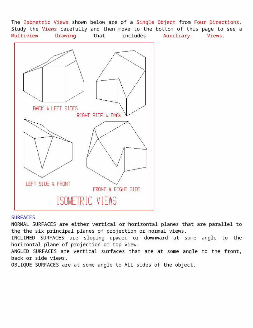
AUXILIARY VIEWS & TERMINOLOGYThe Isometric Views shown below are of a Single Object from Four Directions. Study the Views carefully and then move to the bottom of this page to see a Multiview Drawing that includes Auxiliary Views.
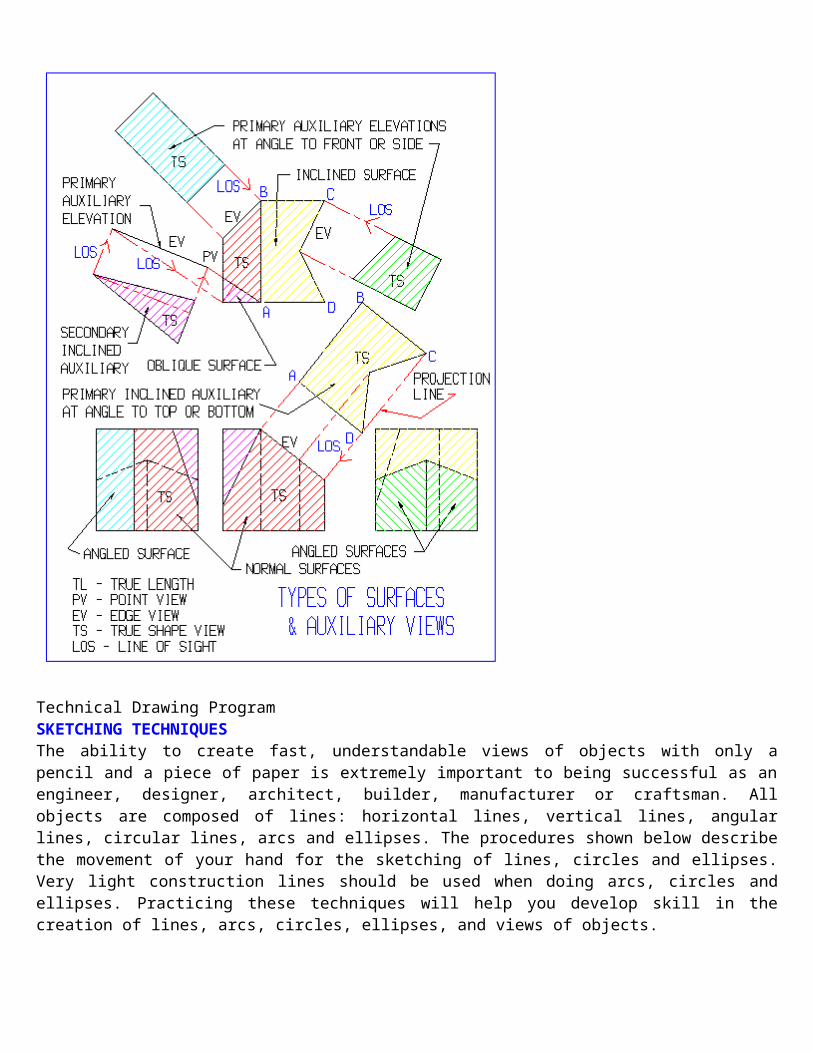
SURFACESNORMAL SURFACES are either vertical or horizontal planes that are parallel to the the six principal planes of projection or normal views.INCLINED SURFACES are sloping upward or downward at some angle to the horizontal plane of projection or top view.
ANGLED SURFACES are vertical surfaces that are at some angle to the front, back or side views.OBLIQUE SURFACES are at some angle to ALL sides of the object.
Technical Drawing ProgramSKETCHING TECHNIQUESThe ability to create fast, understandable views of objects with only a pencil and a piece of paper is extremely important to being successful as an engineer, designer, architect, builder, manufacturer or craftsman. All objects are composed of lines: horizontal lines, vertical lines, angular lines, circular lines, arcs and ellipses. The procedures shown below describe the movement of your hand for the sketching of lines, circles and ellipses. Very light construction lines should be used when doing arcs, circles and ellipses. Practicing these techniques will help you develop skill in the creation of lines, arcs, circles, ellipses, and views of objects.
Technical Drawing ProgramDIMENSIONING RULES & COMMON PRACTICES
The following rules and common practices are based on ANSI Y14.5M - 1988 and should serve as guides to good dimensioning techniques:
1. The first dimension line is spaced a minimum of 3/8" or 10 mm from the view and 1/4" or 6 mm for additional dimensions.
2. Extension lines are started about 1/16" or 1 mm from the object and extend beyond the last dimension line about 1/8" or 2 mm.
3. If the "Aligned System" of dimensioning is used, all horizontal dimensions are read from the bottom edge of the paper and all vertical dimensions are read from the right-hand edge of the paper. This system is commonly used on architectural and civil engineering drawings.
4. If the "Unidirectional System" of dimensioning is used, all dimensions are read from the bottom edge of the paper. This system is used extensively on mechanical and related engineering drawings.
5. When all of the dimension values are expressed in inches, the inch symbol (") is omitted. For decimal values of less than 1 inch, omit the zero in front of the decimal point: eg. .25 or .875.
6. When making architectural and structural drawings, use feet and inches: 6'-0 or 10'-6.7. When making civil engineering drawing, use feet only: 1.75' or 250.59'.8. When the Metric system is used for a drawing, the values are expressed in millimeters
and the (mm) is omitted. For values less than 1 mm, place a zero in front of the decimal point.
9. When making a sheet metal drawing, use decimal inches: 1.25 or 25.75.10. When making a furniture drawing, use fractional or decimal inches: 1 1/4 or 1.25.11. When making a machine or product drawing; use decimal inches or millimeters:
1.25 or 31.12. When making an electronic circuit layout, use the coordinate method of
dimensioning from one corner of the circuit board.13. The same dimension is not repeated on multiview drawings.14. Dimensions not required for manufacturing a part should be omitted.15. Overall dimensions are placed outside the smaller dimensions. With the overall
dimension given, one of the smaller distances is not dimensioned unless it is needed for reference; and then it should be indicated by placing ( ) brackets around the value.
16. On circular end parts the center-to-center dimension is given instead of an overall dimension.
17. When it is necessary to place a dimension within a sectioned area, leave a blank space for the number.
18. Dimensions are given from center lines, finished surfaces or datums where necessary.
19. Never use a center line or a line of the view as a dimension line.20. Never have a dimension line as a continuation of a line of a view.21. Never have a dimension line where it is crossed by a line or another dimension
line.

22. Always give the diameter of a hole, not the radius. A Ø symbol is used before the value and add a leader.
23. Always give the diameter of a cylindrical shape as a normal dimension and include the Ø symbol with the value.
24. Always give the radius of an arc using a leader. An "R" should be placed after the value.
25. Arcs of equal size such as "Fillets and Rounds" can be given in a note: eg. ALL FILLETS & ROUNDS = .125R.
26. Dimensions are generally not placed inside the view outlines.27. Extension lines are placed so they do not cross dimension lines.28. Avoid dimensioning to hidden lines.29. Take time to plan the location of dimension lines. Avoid crowding by providing
adequate space (1.5" or 400 mm minimum) between views for the dimensins.30. Place dimensions between views when ever possible.31. Place dimensions on the view that shows the most detailed contour of a part or
feature.32. Dimension and extension lines should be thin, but dark and should contrast
noticeably with visible lines of the drawing.33. Show dimensions between points, lines or surfaces which have a necessary and
specific relationship to each other.34. State each dimension clearly so the intent can be interpreted in only one way.35. The number of dimensions must be sufficent complete for size, form and location
of features so that no scaling of the drawing, calculating nor assuming of distances is necessary.
36. The dimension value is placed at a break in the dimension line on engineering drawings.
37. Architectural dimension lines are solid with the value placed above the dimension line.
38. Arrowheads should be drawn using the open style and must be dark to indicate the beginning and end of a distance.
39. Slashes at a 45 angle or in some cases dots are used as arrowheads on architectural drawings.
40. Overall length and width on a floor plan are repeated on opposite sides of the building as a convinence for the builder.
41. Leaders are drawn at an angle between 15 and 75 degrees from horizontal or vertical center lines and should point to the center of an arc or circle.
NOTE: The American National Standard, ANSI Y14.5M, for the "Dimensioning and Tolerancing of Engineering Drawings and Related Documentation Practices" should be adhered to for uniformity and acceptance by other concerns. It must be remembered that there are no absolutely hard and fast rules, nor any practice, not subject to change or modification under special conditions or requirements of a particular industry. When there is a variation of any rule, there must always be a reason which can be completely justified.VectorWorks “SHS” Dimension Screen
How to create “Custome Dimension”xxFile - Preference - Document PreferencesxxxxDimensions

xxxxxxCustomxxxxxxxxNew - “Give a name”xxxxxxxxxxEdit
Technology Education DepartmentTechnical Drawing Program
Window and Door Symbols
forFloor Plan Sketches
The symbols shown below represent the common types of windows and doors used on floor plan sketches.See DESCRIPTIONS below drawing for alternate sizes.Sizes will vary from company to company.
WINDOWSDouble hung windows consist of two frames per unit that slide up and down. Single unit widths: 22" to 46" with heights: 36" to 76". Combination unit widths: 44" to 138" depending on the number of frames and size of the frames.Casement windows consist of one to six frames per unit attached horizontally that swing outward using a crank. The center frames on 3, 4, 5 and 6 frame combination units can be fixed in place. Single frame widths: 17" to 36" with heights: 24" to 72". Combination unit widths: 34" to 144" depending on the number of frames and size of the frames.Sliding windows consist of two frames per unit that slide back and forth horizontally. Single unit widths: 36" to 60" with heights: 22" to 60".Awning windows consist of one to four frames per unit stacked vertically that swing outward from the top of the frame. Awning windows can be placed below picture windows. Single frame widths: 24" to 72" with heights: 17" to 40". Combination unit widths: 24" to 144" depending on the number of frames and size of the frames.Hopper windows consist of one frame per unit that swings inward from the bottom of the frame. Hopper windows can be placed below picture windows. Single frame widths: 24" to 72" with heights: 17" to 40".

Picture windows consist of one frame that is fixed in place and does not open. Double hung or casement windows can be combined with picture windows. Widths: 36" to 72" Heights: 36" to 72"Bay windows (NOT SHOWN) project outward from the exterior wall of a house and consist of a picture window with two double hung or casement windows per unit at 30° or 45° to the wall. Widths: 64" to 112" Heights: 38" to 74" Projection: 14" to 19".Bow windows (NOT SHOWN) project outward on a curve from the exterior wall of a house and contain all casement units . Widths: 74" to 164" Heights: 38" to 74" Projection: 6" to 27".DOORSExterior doors are 36", 42", or 48" in width, 80", 84" or 96" in height, and 1 3/4" or 2" in thickness. Sidelites from 10" to 14" in width can be added to one or both sides of an exterior door to provide light and a view when exterior doors contain no windows.Interior doors are 30", 32", 34", or 36" in width, 80" or 84" in height, and 1 1/4" or 1 1/2" in thickness. NOTE: 28" wide doors may be used in powder rooms.Pocket doors are 30", 32", 34", or 36" in width, 80" in height, and 1 3/8" in thickness. A pocket door must have an amount of open wall space equal to the width to slide into the thickness of the wall on a track mounted above the door.Double or "French" doors (NOT SHOWN) are 18", 24", 30" or 36" in width, 80 " or 96" in height, and 1 3/8" (interior) or 1 3/4" (exterior) in thickness. Two doors form a unit that is hinged at the sides with knobs or handles in the center. Double doors may swing into a room but outward if used on a closet. French doors typically swing toward the outside of a structure.Sliding Patio doors are 30", 36", or 48" in width, 80" or 83", or 96" in height and 1 3/4" in thickness. Two or four doors form a unit for overall widths of 60", 72", 96", 117", 141", or 189".Hinged Patio doors (NOT SHOWN) are 30", 32", or 36" in width, 80" or 83", or 96" in height and 1 3/4" in thickness. Two or three doors form a unit for overall widths of 60", 64", 72", 96" or 108".Bifold closet doors are 12", 18" or 24" in width, 80" in height, and 1 1/4" or 1 3/8" in thickness. Two doors form a unit that is hinged at the center and slide open on a track at the top of the door frame. Single units (2 doors) fit openings 24", 36" and 48" wide. Double units (4 doors) fit openings 48", 72", and 96".Sliding closet doors are 30" or 36" in width, 80" in height, and 1 1/4" or 1 3/8" in thickness. Two doors form a unit that slide in front of each other on a track at the top of the door frame. Sliding units (2 doors) fit openings 60" and 72" wide.Double closet doors are 18", 24", 30" or 36" in width, 80 " or 96" in height, and 1 3/8" in thickness. Two doors form a unit that is hinged at the sides with knobs or handles in the center. Double closet doors must swing into a room.Garage doors (NOT SHOWN) are 96", 108" or 192" in width, 84" or 96" in height, and 1 1/4" or 1 3/8" in thickness. Overhead garage doors consist of four or five panels hinged along the length that follow tracks as raised vertically from the floor. FASTENERSExterior Thread Terms

Note: Typical thread angle is 60 degrees.Interior Thread Terms

Technology Education DepartmentIntroduction to Technical Drawing
DESIGN PROCESSThe "Design Process" is a systematic procedure used in industry to change ideas into useable products for consumers or other manufacturers. This procedure is used by designers, engineers, architects, technicians, drafters, detailers and illustrators to prepare a set of plans and specifications that guide machinists, welders, sheet metal workers, casting and molding operators, electronic technicians, painters and many other skilled workers in the completion of their work. The number of phases and/or steps in the process will vary from company to company or textbook to textbook but should include the following:
1. Identify, analyze and research the problem to obtain a complete description of the project;
2. Think of possible solutions to the problem and make freehand, multiview and/or pictorial sketches of all ideas for solving the problem;
3. Discuss all ideas with other designers, engineers, supervisors and managers; 4. Revise and combine ideas after discussions into a "final" solution sketch: 5. Prepare a design layout drawing to scale from the final solution sketch; 6. Prepare scale detail and assembly drawings of all parts and sub-assemblies; 7. Prepare complete specifications and a materials list of all parts: 8. Make individual parts, inspect parts for accuracy, and assemble the parts to make a
working prototype or scale model; 9. Check assembly of parts and test the operation of the prototype for accuracy,
reliability, and safety. 10. Revise detail and assembly drawings if necessary and prepare technical
illustrations for manuals and brochures. The "Design Process" as described above is incorporated in all of the Technical Drawing courses in the Technical Drawing Program at Stevenson High School; provides the basic course outline for the Introduction to Technical Drawing or Technical Drawing for Designers and Drafters; and is used to solve a variety of problems from simple to complex products.Return to Information Sheet 3Entire contents Copyright ©1998. All rights reserved. [Updated: 2/11/99]