genetic algorithm synthesis of low-loss multi-layer negative
TRANSCRIPT
Genetic Algorithm Synthesis of Low-Loss Multi-layer Negative Index Metamaterial Stacks for the Mid-Infrared
Jeremy A. Bossard1, Seokho Yun, Yan Tang, Douglas H. Werner2, and Theresa S. Mayer
Department of Electrical Engineering, The Pennsylvania State University
204 Electr. Engr. East, University Park, PA 16802, United States
1E-mail: [email protected]
2E-mail: [email protected]
Abstract In order to realize practical applications for negative index metamaterials at optical wavelengths, it is necessary to develop design and fabrication techniques for bulk materials. This paper presents one such design methodology employing stacked Frequency Selective Surfaces optimized using a Genetic Algorithm for low loss and a negative refractive index. A design example is presented, showing that the loss can be minimized by optimizing a 5-layer stack. Further analysis reveals that the metamaterial properties of the stack are approaching those of a bulk medium.
1. Introduction Metamaterials with a negative refractive index have recently become an exciting reality. In 1968, Veselago first postulated the possibility of left-handed media with a simultaneously negative permeability and permittivity, along with several interesting properties associated with such a material, including backward-propagating waves, reversed Doppler shift, a modified Snell’s law, and near-field focusing [1]. The more recent observation that a material with n = -1 could be formed into a planar “perfect lens” sparked widespread interest in the development and demonstration of negative index metamaterials (NIMs) [2]. However, fabricating bulk metamaterials for infrared/optical devices presents a difficult problem due to the limitations of nano-fabrication techniques that are time-consuming and expensive to use in a layer by layer fashion. Only very recently has a multilayer magnetic metamaterial been demonstrated for infrared/optical wavelengths, using advanced alignment techniques between layers of split ring resonators [3]. We have previously introduced a low-loss NIM design methodology that uses two cascaded Frequency Selective Surface (FSS) screens optimized via a genetic algorithm (GA) in order to achieve a simultaneously negative permeability and permittivity [4]. Here, we extend this methodology to design multilayer FSS metamaterials that can be fabricated without the need for alignment between fabrication layers. A design example for a low loss multilayer FSS NIM will be presented that is optimized by a GA for mid-infrared (IR) operation at a wavelength around 3 µm.
2. Design Concept The NIM structure proposed here consists of multiple cascaded FSS screens sandwiched between layers of dielectric. Polyimide is chosen for the dielectric layers because it is robust and flexible and has very low loss in the mid-IR from 2 µm to 5 µm. The FSS screens are 75 nm thick films of Ag metal patterned by electron beam (e-beam) lithography. The FSS screens each have the same geometry, and perforations in the screen geometry will be matched by air gaps in the polyimide layers. Thus, the stack of alternating Ag and polyimide layers will be deposited and then etched with a single pattern. A GA is used to optimize the metamaterial structure for low loss and a negative effective refractive index. GAs are robust search algorithms that have been widely used in electromagnetics applications [5]. The metamaterial design parameters, including the FSS screen geometry, unit cell dimension, and dielectric layer thicknesses are encoded into a binary string, or chromosome, and an initial population is generated with random chromosome values. This population is then evolved over several generations by evaluating and ranking each member and by crossing over chromosome data from better performing members to fill a new generation. The FSS screen geometry is pixilated into a 10 by 10 unit cell and divided into eight mirrored triangular folds, one of which is encoded into the chromosome. A minimum pixel dimension of 80 nm is set corresponding to the limitations of e-beam lithography. The fitness of each design is evaluated against specified

target metamaterial effective properties. The scattering parameters of the cascaded FSS structure are predicted using a full-wave periodic finite element boundary integral (PFEBI) code [6]. Dispersive material parameters including the measured dielectric constant for polyimide and a published metallic loss model for Ag at optical and IR wavelengths [7] are incorporated into the numerical analysis. The Nicolson, Ross, and Weir (NRW) inversion method is then employed to calculate the effective refractive index neff and impedance Zeff of an equivalent metamaterial slab from the scattering parameters predicted by the PFEBI code [8]. Because the real part of neff is multivalued, the correct root is determined by enforcing the continuity of neff from a low frequency, where there is no magnetic activity (µeff → 1). The minimizing fitness function used in the GA is given by
[ ]22MIN
targetefftargetefffreqsZZnnFitness −+−= (1)
where ntarget and Ztarget are the specified target metamaterial properties and freqs are the frequency points over which the GA will perform its search.
3. Design Results
The design goals provided to the GA were a negative refractive index with minimum absorption (neff = -1+0j) and an impedance match to free space (Zeff = 1+0j). A range of target frequencies from 90 THz to 110 THz around 3 µm was also specified to the GA. The GA optimized a population of 16 members over 100 generations to arrive at the design shown in Figure 1. The unit cell geometry in Figure 1 is shared by all five FSS screens and measures 1.52 µm on a side, and the distance between each FSS screen is 110 nm. As seen in Figure 1 the FSS screen geometry has eight-fold symmetry, so that at normal incidence the two orthogonal polarizations will have the same scattering response.
Figure 1. (left) FSS screen geometry optimized by a GA for low loss and a negative refractive index. (right) Cross-section view of the five-layer cascaded FSS NIM.
Figure 2. Effective index of refractive (left) and impedance (right) for the multilayer FSS NIM design shown in Figure 1.
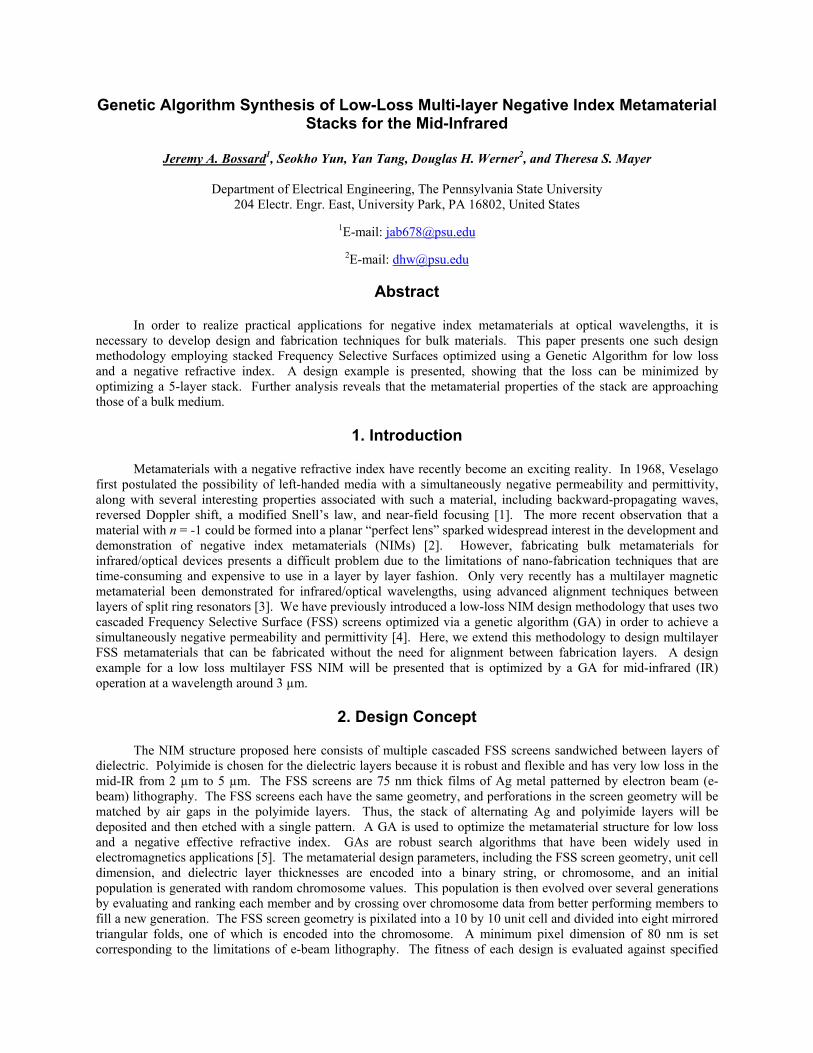
The inverted metamaterial properties are shown in Figure 2, revealing a negative index band around 3 µm. The optimum frequency chosen by the GA is 110 THz, where the predicted effective properties neff = -0.96-0.37j and Zeff = 1.00+0.20j show a negative refractive index with low absorption loss and a good match to free space. The effective constitutive parameters εeff and µeff plotted in Figure 3 reveal that at the negative index band around 3 µm the metamaterial also has a simultaneously negative permittivity and permeability. The permittivity follows a Drude response with a plasma frequency around 116 THz, which is due to the Ag screen connecting across the unit cell. The neighboring screens also form metallic plate resonators, which give rise to the magnetic resonance seen in the permeability plot. The scattering parameters for this design are shown in Figure 4. At the optimum frequency of 110 THz, there is a low return loss of -17.9 dB and a transmission loss of only -3.2 dB.
Figure 3. Effective permittivity (left) and permeability (right) for the multilayer FSS NIM design shown in Figure 1.
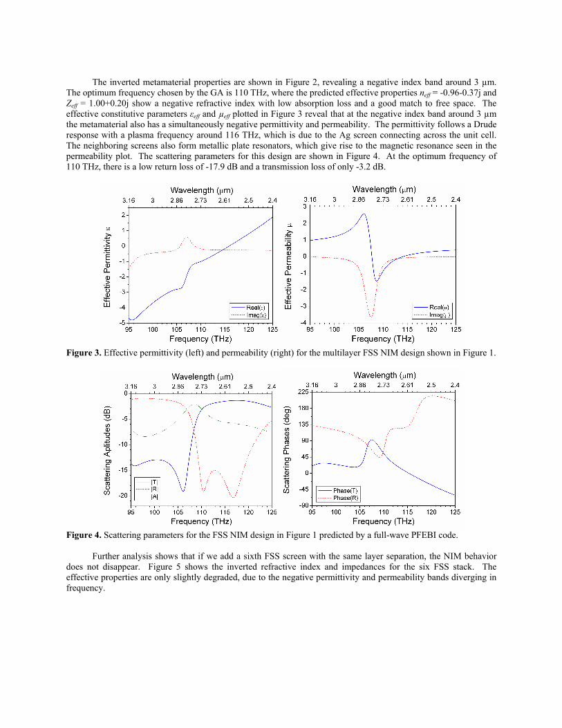
Figure 4. Scattering parameters for the FSS NIM design in Figure 1 predicted by a full-wave PFEBI code. Further analysis shows that if we add a sixth FSS screen with the same layer separation, the NIM behavior does not disappear. Figure 5 shows the inverted refractive index and impedances for the six FSS stack. The effective properties are only slightly degraded, due to the negative permittivity and permeability bands diverging in frequency.
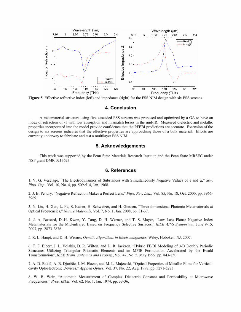
Figure 5. Effective refractive index (left) and impedance (right) for the FSS NIM design with six FSS screens.
4. Conclusion
A metamaterial structure using five cascaded FSS screens was proposed and optimized by a GA to have an index of refraction of -1 with low absorption and mismatch losses in the mid-IR. Measured dielectric and metallic properties incorporated into the model provide confidence that the PFEBI predictions are accurate. Extension of the design to six screens indicates that the effective properties are approaching those of a bulk material. Efforts are currently underway to fabricate and test a multilayer FSS NIM.
5. Acknowledgements
This work was supported by the Penn State Materials Research Institute and the Penn State MRSEC under NSF grant DMR 0213623.
6. References
1. V. G. Veselago, “The Electrodynamics of Substances with Simultaneously Negative Values of ε and µ,” Sov. Phys. Usp., Vol. 10, No. 4, pp. 509-514, Jan. 1968. 2. J. B. Pendry, “Negative Refraction Makes a Perfect Lens,” Phys. Rev. Lett., Vol. 85, No. 18, Oct. 2000, pp. 3966-3969. 3. N. Liu, H. Guo, L. Fu, S. Kaiser, H. Schweizer, and H. Giessen, “Three-dimensional Photonic Metamaterials at Optical Frequencies,” Nature Materials, Vol. 7, No. 1, Jan. 2008, pp. 31-37. 4. J. A. Bossard, D.-H. Kwon, Y. Tang, D. H. Werner, and T. S. Mayer, “Low Loss Planar Negative Index Metamaterials for the Mid-infrared Based on Frequency Selective Surfaces,” IEEE AP-S Symposium, June 9-15, 2007, pp. 2873-2876. 5. R. L. Haupt, and D. H. Werner, Genetic Algorithms in Electromagnetics, Wiley, Hoboken, NJ, 2007. 6. T. F. Eibert, J. L. Volakis, D. R. Wilton, and D. R. Jackson, “Hybrid FE/BI Modeling of 3-D Doubly Periodic Structures Utilizing Triangular Prismatic Elements and an MPIE Formulation Accelerated by the Ewald Transformation”, IEEE Trans. Antennas and Propag., Vol. 47, No. 5, May 1999, pp. 843-850. 7. A. D. Rakić, A. B. Djurišić, J. M. Elazar, and M. L. Majewski, “Optical Properties of Metallic Films for Vertical-cavity Optoelectronic Devices,” Applied Optics, Vol. 37, No. 22, Aug. 1998, pp. 5271-5283. 8. W. B. Weir, “Automatic Measurement of Complex Dielectric Constant and Permeability at Microwave Frequencies,” Proc. IEEE, Vol. 62, No. 1, Jan. 1974, pp. 33-36.