general standard for ancillary and miscellaneous …
TRANSCRIPT

IPS-G-SF- 340
This Standard is the property of Iranian Ministry of Petroleum. All rights are reserved to the owner. Neither whole nor any part of this document may be disclosed to any third party, reproduced, stored in any retrieval system or transmitted in any form or by any means without the prior written consent of the Iranian Ministry of Petroleum.
GENERAL STANDARD
FOR
ANCILLARY AND MISCELLANEOUS
SAFETY AND FIRE EQUIPMENT
ORIGINAL EDITION
MAY 1997
This standard specification is reviewed and updated by the relevant technical committee on Dec. 2002. The approved modifications are included in the present issue of IPS.
May. 1997
IPS-G-SF- 340
1
CONTENTS : PAGE No.
0. INTRODUCTION ............................................................................................................................. 2
1. SCOPE ............................................................................................................................................ 3
2. REFERENCES ................................................................................................................................ 3
3. DEFINITIONS AND TERMINOLOGY ............................................................................................. 4
4. UNITS .............................................................................................................................................. 6
SECTION 1
5. ANCILLARY FIRE FIGHTING EQUIPMENT.................................................................................. 7
5.1 General ..................................................................................................................................... 7
5.2 Equipment Attached to Fire Hose and Fire Pump ............................................................... 7
5.3 Fire Fighters Miscellaneous Tools and Gears ................................................................... 21
5.4 Emergency Lighting Sets (Fig. 14) ...................................................................................... 23
5.5 Fire Alarm and Pocket Alerter ............................................................................................. 25
SECTION 2
6. MISCELLANEOUS SAFETY EQUIPMENT ................................................................................. 27
6.1 General ................................................................................................................................... 27
6.2 Industrial Safety Net ............................................................................................................. 27
6.3 Safety Signs, Color and Motivation Signs.......................................................................... 28
6.4 Air Mover Ventilators (Fig. 20) ............................................................................................. 37
6.5 Safety Torch and Lantern..................................................................................................... 38
6.6 Safety Showers and Eye Wash (Fig. 23) ............................................................................. 40
APPENDICES
APPENDIX A..................................................................................................................................... 41

May. 1997
IPS-G-SF- 340
2
0. INTRODUCTION
This Standard provide the minimum requirements for miscellaneous safety and fire equipment which should be made available for use in an emergency situations. Every piece of ancillary devices has special use in fire fighting and rescue operations. There are also certain safety gears that will help prevention of accident and explosion, also the introduction of color signs act as a guideline to safe working conditions.

May. 1997
IPS-G-SF- 340
3
1. SCOPE
This Standard specifies the minimum requirements for ancillary equipment put in service for use by fire fighters on occasions and circumstances found necessary. The Standard is formed in two parts:
SECTION 1 Ancillary Fire Fighting Equipment
SECTION 2 Miscellaneous Safety Equipment
Note:
This standard specification is reviewed and updated by the relevant technical committee on Dec. 2002. The approved modifications by T.C. were sent to IPS users as amendment No. 1 by circular No 158 on Dec. 2002. These modifications are included in the present issue of IPS.
2. REFERENCES
Throughout this Standard the following dated and undated standards/codes are referred to. These referenced documents shall, to the extent specified herein, form a part of this standard. For dated references, the edition cited applies. The applicability of changes in dated references that occur after the cited date shall be mutually agreed upon by the Company and the Vendor. For undated references, the latest edition of the referenced documents (including any supplements and amendments) applies.
BSI (BRITISH STANDARD INSTITUTION)
BS CP 93 (1972) "The Use of Safety Nets on Constructional Works"
BS 336 "Specification for Fire Hose Couplings and Ancillary Equipment"
BS 750 "Specification for Underground Hydrant and Surface Box Frame"
BS 2752 "Specifications for Chloroprene Rubber Compound"
BS EN 1263 "Requirement for erection of safety net"
BS 3102 “Brass Eyelets and Washers for General Purposes”
DIN (DEUTSCHES INSTITUTE FUR NORMUNG EV.)
DIN 32767 (1984) "Industrial Safety Nets and Safety Nets Accessories"
Manual Firemanship HM-50 Home Office Fire Department, book 2 part 2 & book 7 part 2.
IPS (IRANIAN PETROLEUM STANDARDS)
IPS-G-SF-100 "Fire Fighting Trucks"
ISO (INTERNATIONAL ORGANIZATION FOR STANDARDIZATION)
ISO 3461 (1988) "General Principles for the Creation of Graphical Symbols"
ISO 3864 (1984) "Safety Colors and Safety Signs"
ISO 80416-2 "Graphical Symbols-Use of Arrows"

May. 1997
IPS-G-SF- 340
4
ISO 7000 (1989) "Graphical Symbols for Use on Equipment Crane"
ISO 13200 (1985) "General Principles for Safety Signs and Hazard Pictorials"
3. DEFINITIONS AND TERMINOLOGY
3.1 Axes
1) Large Axes used for breaking in or cutting.
2) Fireman Axes used by fire fighters.
3.2 Blank Cap
A cover fitted to delivery, inlet and suction connection when not in use.
3.3 Branch Holder
A device for taking part of the weight and reaction of a branch at work.
3.4 Collecting Breeching
A fitting used to join two line of hose to form one.
3.5 Control Breeching
A breeching fitted with a valve or valves to shut off the flow of one or both line.
3.6 Dividing Breeching
A fitting used to divide one line of hose into two.
3.7 Collecting Head
Used to connect one or more lines of hose to the suction inlet of a pump.
3.8 Crow Bar
Crow bar has a chiesel edge at one end and a clow at the other.
3.9 Door Breaker
A device for breaking in door or forcing it off its hinges in order to effect an entry.
3.10 Ejector Pump
A portable jet pump designed for removing water from depth beyond the reach of pump suction.
3.11 Fire Hydrant Key and Bar
A tool used to open up a hydrant and to turn on the valve.
3.12 Flow Gage
For attaching to hydrant to measure the flow and pressure.

May. 1997
IPS-G-SF- 340
5
3.13 Hose Binder
Used to secure hose to the couplings.
3.14 Hose Ramp
A device to enable vehicle to pass over delivery hose without damage to the hose.
3.15 Padlock Remover
A lever fitted with shots into which a padlock is inserted. It is used to twist of a padlock when affecting an entry.
3.16 Rubber Gloves
Gloves for use where electrical wires or apparatus are involved.
3.17 Stand Pipe
Used on a hydrant to bring the outlet above the ground level.
3.18 Steel-Shot Lever
A large wooden lever steel shot for lifting heavy objects and forcing doors etc.
3.19 Basket Strainer
Used over the suction strainer to prevent the entry of dirt and leaves etc.
3.20 Suction Strainer
A metal strainer connected to the end of suction hose to prevent the entry into the suction of objects liable to choke or damage the pump.
3.21 Suction Wrench
Used to tighten the suction couplings.
3.22 Siren
A fire alarm.
3.23 Pocket Alerter System
A call-out system using radio pocket alerter.
3.24 Pocket Alerter Charger
A small portable unit used for recharging pocket alerter.
3.25 Volcanizing Outfit
Used for patching of fire hose.

May. 1997
IPS-G-SF- 340
6
3.26 Safety Net
A safety net is a net designed to prevent persons and objects from falling and to catch persons or objects if they fall.
3.27 Safety Anchor
A protective equipment used in conjunction with safety belt and harness to protect the user against falling and arrest his fall.
3.28 Eye and Face Wash
Suitable facilities for quick drenching or flushing of eyes and body where any person is exposed to injurious and corrosive materials.
3.29 Safety Can
Using to store and handle flammable liquid safely.
3.30 Safety Matches
When struck against a surface its head will ignite successfully and consistently.
3.31 Safety Sign
A sign that gives a message about health and safety by a combination of geometric form, safety color and symbol or text.
4. UNITS
This Standard is based on International System of Units (SI), except where otherwise specified.

May. 1997
IPS-G-SF- 340
7
SECTION 1 5. ANCILLARY FIRE FIGHTING EQUIPMENT 5.1 General In this Section ancillary items of fire fighting equipment which are normally used in fire service are explained. They are designed to provide a reliable and efficient service only if they are properly used and given correct care and maintenance. Improper use may lead to premature failure which can result in greater damage during actual fire fighting operations. This Part is categorized as follows:
a) Equipment attached to the fire hose and fire pump. b) Fire fighters tools and gears. c) Emergency lighting sets. d) Fire alarms and pocket alerters.
5.2 Equipment Attached to Fire Hose and Fire Pump 5.2.1 Blank cap A blank cap is used for blanking-off an outlet or an inlet such as pump outlet or suction inlet. It consists of a metal casting blanked off at one end with a male or female coupling connection. Blank cap with male instantaneous coupling is used for blanking off female delivery and instantaneous female blank cap is used for blanking off male instantaneous outlets. A blank cap for use on suction inlet has a round thread of appropriate size. 5.2.1.1 Blank caps shall be made in accordance with BS 336 and attached to the equipment with "S" hook and chain with brazed, welded or integrally cast joints. 5.2.2 Branch holders (see Fig. 1) Branch holders are designed to place in position or adjust to direct the jet in the required trajectory position, and left unattended. 5.2.2.1 The branch holders can be made locally.
TWO TYPES OF PORTABLE BRANCH HOLDER
Fig. 1
5.2.3 Collecting and dividing breeching (see Figs. 2 and 3)
Breeching are generally used for two purposes:
a) uniting two lines of hose into one;

May. 1997
IPS-G-SF- 340
8
b) dividing one line of hose into two.
5.2.3.1 Dividing and collecting breeching shall be constructed in accordance with Clause 9 BS 336 (1989) and shall consist of a three-way branch body at 60°. Dividing breeching shall be provided with two female instantaneous outlets of single lug, twist release type and single male inlet.
Collecting breeching shall be provided with one female outlet of single lug twisted release type and two male instantaneous inlets.
Dividing and collecting breeching may have facilities for controlling the flow of water by means of a valve:
1) With instantaneous couplings;
2) a control breeching.
DIVIDING BREECHINGS
Fig. 2

May. 1997
IPS-G-SF- 340
9
1) With standard instantaneous couplings; 2) breeching for use with a monitor.
COLLECTING BREECHINGS Fig. 3
5.2.4 Collecting head Suction collecting heads shall be one of the following types (Fig. 4).
a) In-line pattern fitted with swivel outlet. b) Angle pattern fitted with a swivel outlet. c) Radial pattern fitted with fixed outlet.
5.2.4.1 Outlet connection Outlet connection shall be female screw threads of appropriate size in accordance with BS 336, Table 6. 5.2.4.2 Inlet connections Inlet connections shall be male instantaneous in accordance with BS 336 and shall be attached to the collecting head by screw ends, flanges or welding. The space between centers of inlet connections shall not be less than:
115 mm for in-line pattern 134 mm for radial pattern
5.2.4.3 Non-return valves Each inlet connection shall be fitted with a non-return valve which shall show no sign of visible water leackage when tested at a pressure of 17 bar as described in BS 336 Appendix F. The non-return valve shall be either:
a) of spring loaded mushroom type; b) of the flap valve type for in-line and angle pattern collecting head only. The valve shall open to not less than 60° and shall not open to any position where it may jam. The collecting head shall be marked "TOP" in letters of not less than 20 mm in height on the side of the body at which the flap valve is hinged.

May. 1997
IPS-G-SF- 340
10
d) Radial pattern (plan) e) Radial pattern (elevation)
SUCTION COLLECTING HEADS
Fig. 4
All dimensions are in millimeters.
5.2.5 Standpipes
5.2.5.1 Standpipe shall comprise of a shaft, a swivel head and shall be in accordance with BS 336 (Fig. 5).

May. 1997
IPS-G-SF- 340
11
5.2.5.2 Standpipe shaft
The standpipe shaft shall be fitted with a base having the dimension in accordance with BS 336 and as given in Fig. 5 and capable of engagement with fire hydrant (underground type) complying with BS 750. The shaft shall also be fitted with a means of attachment to the swivel head. The washer shall be dressed leather, natural rubber or chloroprene leather to BS 2752.
5.2.5.3 Swivel head
The swivel head shall be fitted with a means of attachment to the shaft and shall have one or two outlets. Each outlet shall be fitted with an instantaneous female connector complying with requirement of Clause 8.1 of BS 336. The bend in swivel head shall have a radius at the center of the bend of not less than 75 mm.
5.2.5.4 Blank cap
Double outlet head shall be provided with a blank plug.
5.2.5.5 Means of attachment
The swivel head shall be attached to shaft by one of the following means:
a) An instantaneous delivery hose coupling except that the tailpiece is not required.
b) A gland that will allow continuous rotation of the head through 360°.
Where delivery hose coupling is used the female coupling shall be on the standpipe shaft.
5.2.5.6 Strength
The standpipe shall show no damage or permanent deflection when tested as described in Appendix D of BS 336.

May. 1997
IPS-G-SF- 340
12
STANDPIPES
Fig. 5
All dimensions are in millimeters.

May. 1997
IPS-G-SF- 340
13
5.2.6 Hydrant key and bar
5.2.6.1 The dimension of the hydrant by socket shall be in accordance with Fig. 6:
MINIMUM DIMENSIONS OF A*
A
Steel
Aluminum
Alloy
Round (q A)
Square (A sq)
٦١٫٤
46.9
٦٩٫٤
54.9
* Giving minimum webs of 6 mm for steel and 10 mm for aluminum alloy.
All dimensions are in millimeters.
HYDRANT KEY SOCKET
Fig. 6
5.2.6.2 The length of key shall be sufficient to allow the bar to clear adjacent standpipes or other obstructions. The bar should fit easily into the key eye.
5.2.6.3 The hydrant key and bar can be made locally by the following materials:
Key end casting
Shaft tube high grade steel pipe of 30 mm
bar high grade steel bar of 25 mm
5.2.6.4 Resistance to torsion and bending The key shall not sustain any damage or permanent deformation exceeding 2° when successfully tested as described in Clause 15-3 of BS 336. 5.2.6.4.1 Torque test Support the key either vertically or horizontally between a spindle cap and a suitable restraint for the bar. Apply a torque of 800 N/m without introducing any bending stress in the key. 5.2.6.4.2 Bending test Locate the key on a fixed spindle, apply a force of 1375 N at right angles to the axis of the key at a distance of 940 mm from the base. 5.2.7 Hose binder (Fig. 7) 5.2.7.1 General
a) The standard method of securing hose to delivery and suction hose couplings which have serrated and ribbed type tails is by bending the hose on the tail with copper or

May. 1997
IPS-G-SF- 340
14
galvanised mild steel wire. This is done by means of a hose coupling binder of which there are various types. b) It is preferable that the binder which is used in fire service to have adaptors to enable suction as well as delivery hose couplings to fit the binder.
5.2.7.2 The method of binding
a) A fixed threaded supporting spindle attached to a bracket screwed to bench has at its outer end a plate with a hold anchoring pin. On the outer side of this plate is an interchangeable adaptor to which the coupling is fitted. The hose to be attached is supported on an x shaped wooden crutch and a piece of canvas or sometimes leather is laid around it where the binding will fall to protect the hose from damage by the wire. The whole of the apparatus except the plate and adaptor revolves around a threaded pivot on the spindle from the spool of wire. The free end is led under tension beneath the guide wheel and groove guide over the coupling, and is threaded through the eye of the anchoring pin. b) The method of securing hose to the couplings The securing method shall be in accordance with Manual Firemanship, Book 2: Part 2.
5.2.7.3 The hose binder can be manufactured locally.
HOSE BINDER
Fig. 7 5.2.8 Suction coupling wrenches (Fig. 8) 5.2.8.1 The suction coupling wrenches shall be universal type and shall fit to any size of suction couplings. 5.2.8.2 The wrench can be manufactured locally. It consist of a tubular steel shank with one end flattened slightly curved and shaped at the end in semi-circular recess. A reinforced strip steel lever arm is pivoted to the bar about 180 mm from the bottom end. The lever arm is also slightly curved and has elliptical shaped eye about 25 mm from its end. The wrench shall be made of mild steel.

May. 1997
IPS-G-SF- 340
15
SUCTION HOSE WRENCHES: (1) CONVENTIONAL TYPE; (2) UNIVERSAL TYPE
Fig. 8
5.2.9 Flow gage (Fig. 9)
5.2.9.1 General
The flow of water per minute as well as pressure can be ascertained by means of flow gage. It consist of flow tube, having a male connection at one end for attaching to a standpipe head or a hydrant female instantaneous outlet and swivel joint at the outer end to which the manometer is connected.
5.2.9.2 The manometer shall have three ranges of flow marked on it:
a) The standard range 7.2 to 34 Lt/s.
b) Low range of 2.6 to 7.2 Lt/s and.
c) Top range of 34 to 60 Lt/s.
5.2.9.3 A pressure gage graduated in meters head or bar with male instantaneous coupling having pressure release vent cock.
5.2.9.4 Testing of flow shall be in accordance with Manual of Firemanship Book 7: Part 2.
5.2.9.5 A wooden casing shall be provided to store the flow gage, pressure gage, monometer and compensator when not in use.

May. 1997
IPS-G-SF- 340
16
AN EXAMPLE OF ONE MODEL OF FLOW GAGE FOR TESTING HYDRANTS
Fig. 9
5.2.10 Hose ramp (Fig. 10)
5.2.10.1 General
Several types of wooden hose ramps which consist of wedge shaped piece of wood joined by either straps, ropes of strips of condemned hose so as to provide channels of about 90 mm wide into which charged hose can be laid. The ramp makes an incline on each side to carry the wheels of vehicular traffic safely over the hose.
5.2.10.2 A ramp shall be fitted on each side with apron of old hose or belting to obviate the ramp tendency to drag or be pushed along by vehicles wheel.

May. 1997
IPS-G-SF- 340
17
HOSE RAMPS
Fig. 10
5.2.11 Suction strainers (Fig. 11)
5.2.11.1 General
There are two types of suction strainers used in fire service pumps suction hoses:
a) Metal strainers.
b) Basket strainers.
These are designed and used to prevent solid objects which might damage the pump from being drawn up through the suction hose when working from open water.

May. 1997
IPS-G-SF- 340
18
1) typical metal strainer;
2) a low-level strainer;
3) the basket strainer used in conjunction with the metal strainer.
STRAINERS
Fig. 11
5.2.11.2 Metal strainers (Fig. 11.1)
Metal strainers shall be made of copper alloy resistant to corrosion and shall be provided with fixed outlet having a female screw threads of appropriate size in accordance with Clause 18 of BS 336 ( Figs. 15e & 16c).
5.2.11.3 The cylindrical perforated sheet shall have brazed or welded seams dressed smooth on both surfaces and shall not be less than 1.50 mm thick. The end shall not be less than 2.00 mm thick. The joints to the outlet and to the end shall be riveted, welded or brazed.
5.2.11.4 The washer shall be of dressed leather, natural rubber or chloroprene rubber.

May. 1997
IPS-G-SF- 340
19
5.2.11.5 Basket strainers (Fig. 11-3)
The strainer basket shall be of cane and shall have six bottom sticks. The 75 mm size have 19 stakes and 100 mm size 21 stakes and the 140 mm size 23 stakes with 3 rod borders. There shall be three rounds of upsetting. The first round having four rods. There shall be two double body wales at the center of 75 mm and 100 mm sizes and four round of three rod walings at the center of the 140 mm sizes. There shall be two round of walings under the border on each size with four runner forming stakes.
5.2.11.6 Sleeves
The sleeves shall be constructed as shown in Fig. 18 of BS 336. Brass soil eyelet and rings of one of the types specified in BS 3102 shall be fixed in the center of each hem and shall be equally spaced as follows:
a) 6 eyelets each end for the 75 mm size.
b) 8 eyelets each end for the 100 mm size.
c) 10 eyelets each end for the 140 mm size.
The ends of all cords shall be whipped and stitched to prevent fraying.
5.2.11.7 Cord
One long and one short cord of the lengths shall be inserted in the eyelets of each sleeve and firmly tied to prevent detachment.
5.2.11.8 Low level strainers
To facilitate to pump from shallow water specially designed low level metal strainer illustrated in Fig. 11.2 can be used which is produced to standard sizes of suction hose. Water enter via the bottom of the strainer which stands on four squat legs.
5.2.12 Ejector pump (see Fig. 12)
5.2.12.1 General
There are several various of ejector pumps in use in fire service for pumping water. The ejector pumps have no moving parts. Propulsion is effected by means of water under pressure. Pressurized water emerged in jet from a small internal nozzle enters the delivery tube via an opening known as throat. The narrowest part of the throat is slightly larger than the orifice of the nozzle and is separated from it by a gap which is open to the suction inlet. As the water jet passes the gap and rapidly expands, the consequent fall in pressure at the throat and in suction tube causes atmospheric pressure to force water up to the suction. The water then joins the jet stream and is expelled through delivery.

May. 1997
IPS-G-SF- 340
20
TWO TYPES OF EJECTOR PUMPS
Fig. 12
5.2.12.2 The submersible ejector pump with two stage ejector nozzle and with the strainer suction inlet should be provided.
5.2.12.3 The inlet shall be of instantaneous male coupling (BS 336) and the outlet female suction hose round thread connection of 100 mm and shall be attached to the body by screw, flanges or welding.

May. 1997
IPS-G-SF- 340
21
5.2.12.4 The material shall be of aluminum or copper alloy resistant to corrosion by salt water.
5.2.12.5 The casting shall be clean, sound and free from gross porosity cracks and other surface imperfections.
5.3 Fire Fighters Miscellaneous Tools and Gears 5.3.1 Ropes 5.3.1.1 General Ropes form an important item in the equipment carried on fire service appliances. In order to use a line of rope to maximum advantages it is essential that each one of the fire fighters should be completely competent in the tying of the standard knots, bends and hitches. The fire fighter should be able to make the knots automatically in complete darkness under difficult conditions of urgency as is often necessary. 5.3.1.2 Depending on the condition of risks the following types of ropes may be carried on each fire truck as found necessary. (See Chapters 9 to 14 Manual Firemanship Book 2).
1) General purpose lines. 2) Rescue lines. 3) Lowering lines. 4) Escape lines. 5) Guy lines. 6) Guide lines. 7) Belt lines. 8) Bobbin lines.
5.3.2 General purpose tools 5.3.2.1 Various kind of tools are commonly used in fire services vertually the same as those used in other works. Tools under this heading include spades, pickaxes, mattock, large axes, sledge hammer, steel crow bar, and wedges, carpenter’s tools, such as hammer, woodsaws and chiesels of various kind and sizes, ratchet braces and bits, screw driver, etc. Fitter’s tools such as spanners and wrenches, hacksaws, cold chiesels, pliers and wire cutters. 5.3.2.2 Requirement The following are suggested equipment to be carried on the various appliances, safety and fire authorities shall adopt a stowage plan for small gear and miscellaneous tools for each type of fire appliances. It is essential for every member of crew to know, especially when working in the dark, exactly where he can find each item of equipment carried on the appliances. 5.3.2.3 Emergency and rescue tools The following are suggested equipment and tools to be carried out on the various safety and fire appliances. The choice of various equipment and tools is a matter determined by local requirements and shall be based on the nature of facility and the site specific hazards presont: - Forcible entry tools (specially during car accident operation. - Rescue and first aid equipment. - Hydrolic rescue tools, jacks, cutters, extenders. - Smoke ejectors. - Salvage overhaul equipment. - Ladder. - Portable lighting gears. - Extention cords (electric)

May. 1997
IPS-G-SF- 340
22
ITEM
GENERAL PURPOSE
EMERGENCY APPLIANCE Number Number
Spade ٢ ٥Fireman axe insulated handle Large axe Steel crew bar Chiesel various size Mattock Wedge wooden Sledgehammer Ceiling hook Hearth kit Tool kit First aid kit Steel-shod lever Door breaker
٢ ٦1 1 --- --- 5 --- ---
1 1 --- ---
2 2
1 set 3
10 1 2 1
1 large 1 2 1
Padlock remover persuader lifting equipment
--- --- ---
١1
1 set Chain blocks and tackles Safety torch Full body harness General purpose rope 20 m General purpose rope 10 m
--- 4 --- 1
1
١ set 6 2
2 of 20 meters 1 of 60 meters 2 of 10 meters
Notes: 1) The above table covers only miscellaneous items for fire and emergency equipment carried in each fire truck. For other fire fighting equipment see IPS-G-SF-100. 2) Hearth kit contains bricklayer’s, bolster. 2 cold chiesel, club hammer, insulated pliers, floorboard saw, hacksaw, spare hacksaw blades and screw driver (Fig. 13).
A HEARTH KIT, SHOWING THE TYPE OF BOX IN WHICH THE TOOLS ARE GENERALLY
STOWED Fig. 13

May. 1997
IPS-G-SF- 340
23
THE FIREMAN’S AXE. (1) WITH WOODEN HANDLE; (2)
WITH INSULATED STEEL HANDLE Fig. 13 (continued)
5.4 Emergency Lighting Sets (Fig. 14)
5.4.1 General
5.4.1.1 A very wide variety of lighting sets are used by fire service and vary from conventional hand lamps to flame proof safety lamps and mobile and portable flood lighting. The choice of lamps and lighting sets is a matter determined by local requirements.
5.4.1.2 General purpose hand lamps and lighting sets are not normally gas-proof and shall not be used in conditions where flammable gases and vapors are likely to be present.
5.4.1.3 Search lights and flood lights should provide sustained illumination at the scene of fires and other incidents search lights are designed to throw a concentrated beam of light which is used for such purpose as illuminating a specific part of an incident. Flood lights are designed to give illumination over a wide area and used in circumstances where the whole of working area require illumination.
5.4.2 Safety consideration
To active safe operating condition, the requirement of emergency lighting, specially using of lighting sets with internal combustion engine shall be carefully evaluated. It is obvious that none flameproof equipment shall not be used during any emergencies where the hazard of gas escape may the encountered. Fig. 14 illustrate 3 models of lighting sets with related specifications:

May. 1997
IPS-G-SF- 340
24
1) This is a portable unit equipped with one allweather
projector, having a 1500 Watt halogenous
lamp. The projector is adjustable on the vertical
axis. The unit dimensions are reduced to such an extent
that it can be contained even in the trunk of a
normal car. The unit should be explosion proof.
2) This is a portable unit of reduced dimensions, equipped
with four all weather projectors mounted on a telescopic
mast, each fitted with a 500 Watt halogenous lamp
(total 2000 W). The unit, powered by a diesel engine,
has a tubular frame and hood. The telescopic mast, made
of anodized light alloy, can be extended to a length of
five metres. For transport, which can be carried out by
means of normal vehicles, the mast is retracted, placed
in a horizontal position and clamped to the hood.
The unit should be expiosion proof.
Indicative dimensions:
1050 × 570 × 700 mm (+ mast)
Indicative weight: 135 kg
Current generated:3.5 kVA = 2.8 kW, single-phase, 220 V - 50 Hz
Diesel engine: 3000 RPM, air cooling electric starting.
EMERGENCY LIGHTING SETS
Fig. 14

May. 1997
IPS-G-SF- 340
25
3) This mobile lighting unit is mounted on a single-axle road trailer, suitable for speed towing, with two tyred wheels and a small maneuvering front wheel. A "crown" composed of eight all-weather projectors, each fitted with a 500 Watt halogenous lamp (total 4000 W), is mounted on a tubular telescopic mast made of light alloy. The mast is extended pneumatically and can reach a height of 7.6 metres from the ground. When the unit is not and during transportation the mast is retracted and clamped to the casing. The trailer has torsion-bar suspensions, an overrun brake, a parking brake, rear stabilizers and tail lights. The Standard drawbar is equipped with ball coupling (Φ 50 mm) but can be provided, on request, with towing eye. The generating set is powered by an air-cooled diesel engine with electric starting.
Fig. 14 - (continued) 5.5 Fire Alarm and Pocket Alerter 5.5.1 General 5.5.1.1 Fire call siren (Fig. 15.1) The call out system used in the Company vary according to the types of fire stations and manning arrangements. On stations continuously manned by whole time men the call out system by which they are alerted in most cases comprises of turnout bell. In cases where retained firemen are involved either at part-time or full time, and when a major emergency arise, offduty fire fighters and other responsible authorities shall be alerted, specially, when at home by fire siren. The fire sirens used by fire service vary to a certain extend in size and power, but majority are of four to five horsepower, three phase type. Satisfactory maintenance arrangements shall be made to keep the fire siren in good working order, and they should be inspected and serviced about five to six times a year. As faults are more likely to occur at winter during humid or during cold, rainy and icy weather, these inspections shall be made infrequently. Every siren installation shall be tested not less than once a week.

May. 1997
IPS-G-SF- 340
26
DIAGRAM OF A SIREN
Fig. 15.1 5.5.1.2 Radio pocket alerter (Fig. 15.2) This system can be used instead of siren, specially for unmanned fire stations. The system comprises a base transmitter either installed in a local fire station or in a control room and requisite number of pocket receivers or (alerters) are put at the disposal of fire fighters and other responsible authorities. Each aleter is provided with a buttery charger. The normal receiver of the equipment are those which are continuously on stand by duty ready to receive a triggering signal from the control transmitter.
RADIO POCKET ALETER RECEIVER
Fig. 15.2

May. 1997
IPS-G-SF- 340
27
SECTION 2
6. MISCELLANEOUS SAFETY EQUIPMENT
6.1 General
In this Part of I.P. Standard the following miscellaneous safety equipment is discussed:
a) Industrial safety net.
b) Safety signs, colors and safety motivation signs. Text should be in English and farsi.
c) Safety cans.
d) Air mover ventilators.
e) Safety torch and lantern.
f) Safety showers and eye wash units.
6.2 Industrial Safety Net
6.2.1 General
Safety net is a net designed to prevent persons and objects from falling and to catch persons and objects, if they fall. Depending on their function, safety nets are classified as restraint or retention nets.
6.2.2 Construction
Nets shall be made from man made fiber ropes and plaited cords, with the exception of polyethylene ropes and cords.
The choice of material shall be determined by the circumstances in which the net to be used, the performance required of the net and prevailing conditions.
6.2.3 Design
The net shall be designed and tested as described in Appendix A of BS 3913 (1982) for a duty height of 6 m or 1 m as appropriate.
6.2.4 Dimensions
The minimum nominal size shall be 4m by 3 m Nets shall be made with a square or diamond mesh and the length of the mesh side shall not be greater than 100 mm.
6.2.5 Performance
Safety nets shall be tested as described in BS 3913 or DIN 32767.
6.2.6 Marking and manufacturers certificate
Each net shall have attachment of two different positions, permanent label marked with the following wording in 30 mm letters in height.
Maximum distance below working level × m.

May. 1997
IPS-G-SF- 340
28
The label shall also be marked with:
a) The name or other means of identification of the Manufacturer.
b) The nominal size of safety net.
c) The standard used.
d) The date of manufacture.
The Manufacture shall supply a certificate with each net stating that the tests specified in BS 3913 or DIN 32767 have been carried out.
6.2.7 Erection and dismantling of the net
The erection and dismantling of safety nets are potentially hazardous operation and require careful planning to avoid the exposure of personnel who do this work to unnecessary dangers. Close supervision shall be maintained during erection to ensure that all design requirement have been incorporated correctly.
6.2.8 Use and maintenance
The use, inspection and maintenance of safety net shall be in accordance with BSI CP93.
6.3 Safety Signs, Color and Motivation Signs
6.3.1 General
6.3.1.1 The purpose of a system of safety colors and signs is to draw attention to objects and situations which affect safety and health or:
a) alert persons to an existing and potential hazard;
b) identify the hazard and describe the nature of hazard;
c) explain the consequences of potential injury from the hazard;
d) instruct persons about how to avoid the hazard.
6.3.1.2 The following definitions shall apply:
a) Safety color
A color of special properties to which a safety meaning is attributed.
b) Safety sign
A sign which gives a general safety message obtained by combination of color and geometric shape and which by the addition of graphic symbol or text gives a particular safety message. Text should be in English and farsi.
c) Supplementary sign
A sign with a text only for use where necessary in conjunction with a safety sign.
6.3.1.3 The use of a system of safety color and signs does not replace the need for appropriate accident prevention measures and education is an essential part of any system for giving safety

May. 1997
IPS-G-SF- 340
29
information.
6.3.1.4 The following international standards shall be consulted for additional informations relevant to this Standard:
a) For safety signs and hazard pictorials and graphical symbols:
ISO 3461-1: 1988 "General Principles for the Creation of Graphical Symbols"
ISO 3864 (1984) "Safety Colors and Safety Signs"
ISO 80416-2 "Graphical Symbols-Use of Arrow"
ISO 7000 (1989) "Graphical Symbols for Use on Equipment Crane"
ISO 13200 (1995) "General Principles for Safety Signs and Hazard Pictorials"
b) For traffic safety signs Iranian Traffic Regulations shall be followed:
6.3.2 Safety colors and contrast colors
6.3.2.1 Safety colors
The general meaning defined as specific health and safety colors with contrast colors shall be as given in Table 1:
TABLE 1 - GENERAL MEANING OF SAFETY COLORS AND CONTRAST COLORS
SAFETY COLOR
MEANING OR
OBJECTIVE
EXAMPLE OF USE
CONTRAST
COLOR Red
Stop Prohibition
Stop signs Emergency stops Prohibition signs
White
Yellow
Caution risk of danger Indication of danger (fires, explosion, radiation, toxic. hazard, etc., warning for stops, low passage, obstacles)
Black
Blue Mandatory actions Obligation to wear personal protective equipment White Green
Safe condition Safety message and motivation signs
Escape routes, emergency exist,emergency showers, first aid, rescue station and safety notices such as think! Safety first-notice
White
Note:
Red color is also used to identify fire fighting equipment and its location.
6.3.2.2 The following combination of safety yellow and black may be used to indicate temporary or permanent risk of collusion, falling, stambling, of falling objects, or steps and hole in floor, etc.,
Yellow shall cover at least
50% of the area of the sign.

May. 1997
IPS-G-SF- 340
30
Note:
For colorimetric and photometric properties of safety colors and contrast colors ISO 3864-1984 Annex A, shall be referred to.
6.3.3 Geometric form and meaning of safety signs
Table 2 gives the general meaning of geometric forms.
TABLE 2 - GEOMETRIC FORM AND MEANING
GEOMETRIC
MEANING
Prohibition or mandatory action
Warning
Information (including instructions)
6.3.4 Design of graphic symbols
The design of graphic symbols should be as simple as possible and in accordance with ISO 3461 and detail not essential for understanding the message shall be omitted. Where a symbol is not available or fully understood depending on condition the meaning shall be obtained by using a text in place of a symbol or underneath of the symbol.
Note:
The graphic symbols given in Appendix A are examples. Alternative design may be used provided the symbols comply with the appropriate image content.
6.3.5 Layout of safety signs
The safety colors and contrast colors and geometric forms shall be used only in the following combinations to obtain the four basic types of safety signs as stated in Table 1.
6.3.5.1 Prohibition sign (see Fig. 16)

May. 1997
IPS-G-SF- 340
31
Background color: White
Circular band and cross bar: Red
Symbol of text: Black
The symbol or text shall be placed centrally on the background and shall not obliterate the cross bar. The color red should cover at least 35% of the area of the sign.
6.3.5.2 Warning sign (see Fig. 17 .A.B)
Background color: Yellow
Triangular band: Black
Symbol of text: Black
Warning sings
The symbol or text shall be placed centrally on the background the color yellow shall cover at least 50% of the area of the sign.

May. 1997
IPS-G-SF- 340
32
6.3.5.3 Mandatory action signs (see Fig. 18)
Background color: Blue
Symbol of text: White
The symbol or text shall be placed centrally on the background. The color blue shall cover at least 50% of the area of the sign.
6.3.5.4 Information signs (notices, safe condition, motivation signs think, safety first, etc.)
(Fig. 19)
Background color: Green
Symbol of text: White
The symbol or text shall be placed centrally on the background and the shape of the sign shall be square or oblong as necessary to accommodate the symbol or text. The color green shall cover at least 50% of the area of the sign. For safety motivation signs, the upper panel of each sign has either the word safety first or think in white letter on a green background. The bottom panel has the message in black letters on a white background. 6.3.5.5 Supplementary signs
Background color: White or color of the safety sign Text: Black or relevant contrast color.
The shape of the sign shall be rectangular and shall not comprise any graphic symbol. The supplementary sign shall be underneath the safety sign. 6.3.6 Size of signs Depending on conditions and considering colorimetric and photometric of safety colors the following sizes are recommended for use:
a) 180 × 250 mm b) 250 × 350 mm

May. 1997
IPS-G-SF- 340
33
c) 350 × 500 mm. 6.3.7 Construction The safety sign may be constructed by:
a) 0.80 to 1.50 mm Steel painted baked enamel b) 3 to 4 mm Plastic c) 1½ to 2 mm Aluminum stove enamel d) 5 mm Fiber glass epoxy coated
Safety signs can also be made of scotch light reflective type. They are conventional signs by day and reflect at night when struck by light. They have reflective power up to 230 times greater than a white surface. (See BS. 381 C)
PROHIBITION SINGS
REFERENT
EXAMPLE
Smoking prohibited
Fire, open light and smoking prohibited
Water as extinguishing agent prohibited
Background color: White Circular band and cross bar: Red Symbol of text: Black
Fig. 16

May. 1997
IPS-G-SF- 340
34
WARNING SINGS
REFERENT
EXAMPLE
General warning, caution, risk of danger
Caution, risk of fire
Caution, risk of explosion
Fig. 17 a
(to be continued)

May. 1997
IPS-G-SF- 340
35
(continued)
REFERENT
EXAMPLE
Caution, risk of corrosion
Caution, toxic risk
Caution, risk of electric shock
Background color: Yellow
Triangular band: Black
Symbol of text: Black
Fig. 17 b

May. 1997
IPS-G-SF- 340
36
MANDATORY ACTION SINGS
REFERENT
EXAMPLE
General mandatory action
Eye protection must be worn
Hearing protection must be worn
Head protection must be worn
Background color: Blue
Symbol or text: White
Fig. 18

May. 1997
IPS-G-SF- 340
37
EXAMPLES OF MOTIVATION SIGNS
Fig. 19
6.4 Air Mover Ventilators (Fig. 20)
6.4.1 General
Air mover ventilator is a portable device for moving gases, vapors, smoke, fumes and dust from an area, or to move fresh air into an area. It uses air or steam usually available in industrial locations. Typical application includes, tank or ship-hold purging, furnace or boiler cooling to speed up repairs; evacuating unbreathable or toxic air from working area, blowing fresh air into manholes and closed working space.
6.4.2 Construction
The air mover shall not have moving parts or motors. Compressed air or steam with pressure of 2 to 6 bar can be used. The sizes shall be of 70-140 and 250 mm dia. The air/steam connection for 70 mm to be of 20 mm and for 140-250 mm shall be of 30 mm pipe connections. The design of venture shall be such that the induced air to be of 10 to 14 times of compressed inlet air at 5 bar.
6.4.3 Safety measurement
The air mover shall be grounded to draw-off the static charges during operations.

May. 1997
IPS-G-SF- 340
38
3 TYPES OF AIR MOVER
Fig. 20
6.5 Safety Torch and Lantern
6.5.1 Safety torch (flush light) (Fig. 21)
Safety torch shall be made of plastic that has high mechanical and tensile strength, and is resistant to grease, oils, water and gasoline with the following features:
a) spring mounted safety bulb-guards against explosion following bulb breakage;
b) certified as can be used in pump rooms, storage tanks and places where explosive mixtures of gases and vapors may be a hazard. (See also IPS-M-EL-290);
c) uses two or three dry cell 1½ volts D Type batteries;
d) listed and certified by recognized testing organization as safety torch.
SAFETY TORCH
Fig. 21

May. 1997
IPS-G-SF- 340
39
6.5.2 Safety lantern (Fig. 22)
Safety lantern shall stand on a pivotal base which permits lights to be directed to any location and leaves both hands free with the following features:
a) to throw a piercing shaft of light up to 450 meters;
b) safety bulb socket instantly ejects broken bulb from the battery circuit and helps prevent possibility of explosion in presence of gas;
c) the lense to be of nonbreakable plastic;
d) the base stand to be made of spark proof brace;
e) being of light weight with positive action switch;
f) the batteries to be of dry-cell type;
g) listed and certified by recognized testing laboratory as safety lantern;
h) operate both front light and top lights separately or at once.
SAFETY LANTERN
Fig. 22

May. 1997
IPS-G-SF- 340
40
6.6 Safety Showers and Eye Wash (Fig. 23)
6.6.1 General
6.6.1.1 Safety showers and eye wash facilities shall be provided where eyes and body of employees may be exposed to injurious corrosive materials (Acids, castics and foreign materials).
6.6.1.2 Facilities for quick drenching or flushing of eyes and body within working area for immediate use are of numerous types depending on risk of injuries.
6.6.2 Types
1) Foot treadle actuated eye and face wash pedestal or wall mounted.
2) Quick-push safety lever type with aeriated water fountain.
3) Sink mounted eye wash fountain.
4) Combination eye wash and shower units.
5) Chain pull type emergency shower which sounds a signal when shower turned-on.
TYPES OF SAFETY SHOWER AND EYE WASH
Fig. 23
May. 1997
IPS-G-SF- 340
41
APPENDICES
APPENDIX A
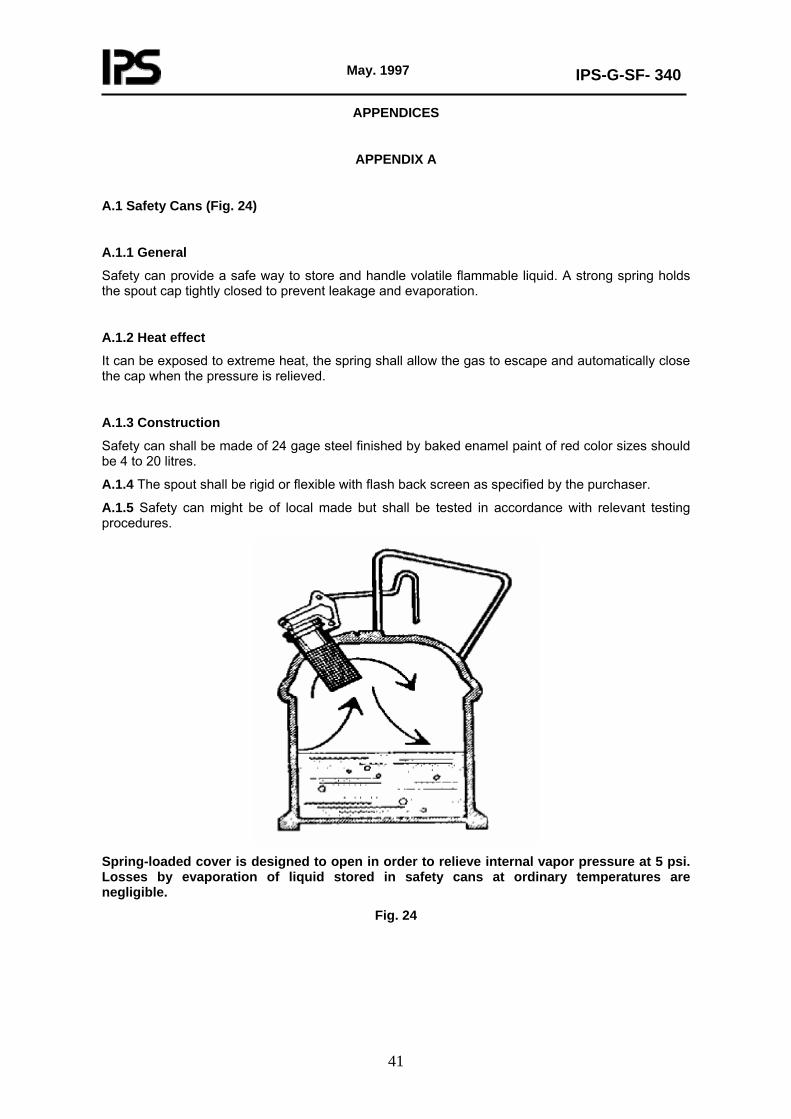
A.1 Safety Cans (Fig. 24)
A.1.1 General
Safety can provide a safe way to store and handle volatile flammable liquid. A strong spring holds the spout cap tightly closed to prevent leakage and evaporation.
A.1.2 Heat effect
It can be exposed to extreme heat, the spring shall allow the gas to escape and automatically close the cap when the pressure is relieved.
A.1.3 Construction
Safety can shall be made of 24 gage steel finished by baked enamel paint of red color sizes should be 4 to 20 litres.
A.1.4 The spout shall be rigid or flexible with flash back screen as specified by the purchaser.
A.1.5 Safety can might be of local made but shall be tested in accordance with relevant testing procedures.
Spring-loaded cover is designed to open in order to relieve internal vapor pressure at 5 psi. Losses by evaporation of liquid stored in safety cans at ordinary temperatures are negligible.
Fig. 24