general specifications 2/4-electrode design for...
TRANSCRIPT
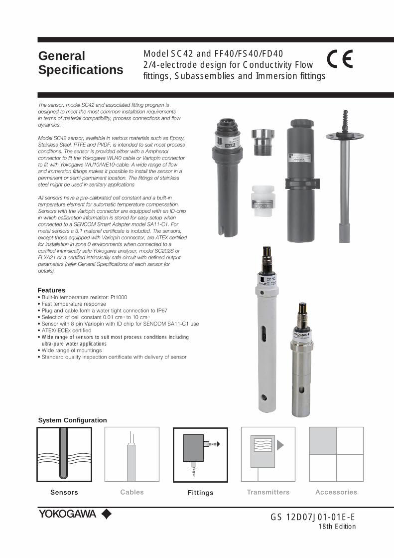
Model SC42 and FF40/FS40/FD40 2/4-electrode design for Conductivity Flow fittings, Subassemblies and Immersion fittings
GS 12D07J01-01E-E18th Edition
The sensor, model SC42 and associated fitting program is designed to meet the most common installation requirements in terms of material compatibility, process connections and flow dynamics.
Model SC42 sensor, available in various materials such as Epoxy, Stainless Steel, PTFE and PVDF, is intended to suit most process conditions. The sensor is provided either with a Amphenol connector to fit the Yokogawa WU40 cable or Variopin connector to fit with Yokogawa WU10/WE10-cable. A wide range of flow and immersion fittings makes it possible to install the sensor in a permanent or semi-permanent location. The fittings of stainless steel might be used in sanitary applications
All sensors have a pre-calibrated cell constant and a built-in temperature element for automatic temperature compensation. Sensors with the Variopin connector are equipped with an ID-chip in which callibration information is stored for easy setup when connected to a SENCOM Smart Adapter model SA11-C1. For metal sensors a 3.1 material certificate is included. The sensors, except those equipped with Variopin connector, are ATEX certified for installation in zone 0 environments when connected to a certified intrinsically safe Yokogawa analyser, model SC202S or FLXA21 or a certified intrinsically safe circuit with defined output parameters (refer General Specifications of each sensor for details).
GeneralSpecifications
Sensors Cables Fittings Transmitters AccessoriesSensors Cables Fittings Transmitters AccessoriesSensors Cables Fittings Transmitters Accessories
System Configuration
Features• Built-in temperature resistor: Pt1000• Fast temperature response• Plug and cable form a water tight connection to IP67• Selection of cell constant 0.01 cm-1 to 10 cm-1
• Sensor with 8 pin Variopin with ID chip for SENCOM SA11-C1 use• ATEX/IECEx certified• Wide range of sensors to suit most process conditions including
ultra-pure water applications• Wide range of mountings• Standard quality inspection certificate with delivery of sensor

2
GS 12D07J01-01E-E
SpecificationsGeneral Specifications
Model SC42Measuring elements 2-electrode for SC42-SP/SV series; SC42-EP04 (EP14); SC42-EP15
(EP16) series 4-electrode for SC42-EP08 (EP18); SC42-FP/FV08 (TP/TV08) Pt1000 temperature sensor
Materials Wetted parts sensor: Body SC42-SP/SV : Stainless Steel AISI 316L SC42-EP : Glass filled epoxy resin SC42-FP/FV : PVDF, Glass SC42-TP/TV : Glass filled PTFE, Glass
Electrodes SC42-SP/SV : Stainless Steel AISI 316L SC42-EP : Graphite impregnated
with epoxy resin SC42-FP/FV : Platinum SC42-TP/TV : Platinum
O-ring SC42-SP/SV : Viton SC42-FP/FV : Viton SC42-TP/TV : Kalrez™
For the -FP/FV and -TP/TV the supplied O-ring for sealing in the fitting is Viton.
Insulation -SP/SV : PEEK 450G, FDA migration tested
Connector: Amphenol: Contacts : gold plated Plug : Polyamide
Variopin: Contacts : gold plated Material : Nickel-plated brass Insulation : PEEK, UL94-V0 IP class : IP67
Functional specifications (at 25°C) Temperature element SC42 : Pt1000 to IEC 751 Nominal Cell Constant SC42-SP/SV24 : 0.1 cm-1 SC42-SP/SV34 : 0.01 cm-1 SC42 (EP08) : 10 cm-1 SC42-EP14 (EP18) : 1 cm-1 SC42-EP15 (EP16) : 1 cm-1 SC42-FP/FV : 10 cm-1 SC42-TP/TV : 10 cm-1Note: The SC42 temperature sensor is designed for
measurement compensation and for indication. It is NOT designed for process temperature control.
Dynamic specifications Response time temperature t90 SC42-SP/SV24 : < 3 min. SC42-SP/SV34 : < 1 min. SC42-EP04 (EP08) : < 3 min. SC42-EP14 (EP18) : < 2 min. SC42-EP15 (EP16) : < 3 min. SC42-FP/FV : < 1 min. SC42-TP/TV : < 1 min.
Operating range Conductivity at actual
process temperature : 1 µS * C.C. – 200 mS * C.C. See Fig. 1: Measuring range of conductivity sensors
Fig. 1 Measuring range of conductivity sensors
Temperature SC42-SP/SV : 0°C to 150°C (32°F to 302°F) SC42-EP : 0°C to 110°C (32°F to 230°F) SC42-FP/FV : 0°C to 110°C (32°F to 230°F) SC42-TP/TV : 0°C to 110°C (32°F to 230°F) Pressure SC42-SP/SV : 0 to 10 bar (0 to 142 PSIG) SC42-EP : 0 to 10 bar (0 to 142 PSIG) SC42-FP/FV : 0 to 10 bar (0 to 142 PSIG) SC42-TP/TV : 0 to 2 bar (0 to 28 PSIG) Cable length for Sensors with
Amphenol connector or Variopin connector directly connected to FLXA analyzer : max. 60 meter with WU10 or
WU10 in combination with WF10 cable and BA10 junction box
For sensors with suffix -VS combined with SA11-C1 : Optional 3 meter WE10 cable
combined with SA11 Smart Adapter
SA11-C1 Smart Adapter : Directly connected to the analyzer using a WU11 cable up to 100 meters or Connected to a BA11 connetion box using WU11 cable upto 100 m. The BA11 connection box is connected to the analyzer using a WU11 cable up to 100m
Regulatory standards (only for SC42 with Amphenol connector) ATEX : Directive 2014/34/EU
by applying: EN 60079-0 EN 60079-11 EN 60079-26
Certificate no . : DEKRA 14ATEX0074 X II 1 G Ex ia IIC T4… T6 Ga
ECEx Applying standards : IEC 60079-0 : IEC 60079-11 : IEC 60079-26 Certificate no. : IECEx DEK 14.0032X
Ex ia IIC T4…T6 Ga Conformity : EAC (Eurasia)
TS (Taiwan)
SC42-SP34SX42-SX34(0.01/cm)
SC4A-002(0.02/cm)
SC42-SP24SX42-SX24
(0.1/cm)
SC4A-010(0.1/cm)
SC42-EP14(1/cm)
SC42-EP15(D)(1/cm)
SC42-EP04(10/cm)
SC202/SC450DC402
SC42-EP18(1/cm)
SC42-EP08SC42-FP08
(10/cm)
100 000 000.00
10 000 000.00
1 000 000.00
100 000.00
10 000.00
1 000.00
100.00
10.00
1.00
0.10
0.01
µS/cm
SC450SC202

3
GS 12D07J01-01E-E
Electrical data for ATEX/IECEx : For sensor input circuit connected to A certified intrinsically safe circuit with the following maximum values: Ui = 14.4 V; Ii = 116.5 mA; Pi = 0.342 W or Certified intrinsically safe Yokogawa Contact Conductivity transmitter Model FLXA21 series or Model SC202S series.
The effective internal capacitance Ci and the effective internal inductance Li of the sensor depends only upon the properties and length of the integral cable.
Special conditions (X) : T6 for Tamb. -30°C to 40°C T5 for Tamb. -30°C to 95°C T4 for Tamb. -30°C to 130°C
Impact on the product shall be avoided. Electrostatic charges on the enclosure shall be avoided. From the safety point of view the circuits shall be assumed to be connected to earth.
Regulatory standards (all types)
CE : Decision 768/2008/EC
Pressure : Directive 2014/68/EU Applying article : 4.3 (Sound Engineering Practice)
- RoHS2 : Directive 2011/65/EU Applying category : 9 (Industrial monitoring and control
instruments)
Shipping details Package size (LxWxH) : 300 x 95 x 73 mm (11.8 x 3.7 x
2.9 inch) Package weight : 0.3 to 0.8 kg (0.7 to 1.8 lbs),
depends on sensor type
Environmental conditions Storage temperature : -30°C to 50°C (-22°F to 122°F)
Installation of SC42 sensors To install the SC42 conductivity sensors in a permanent or semi-permanent location, Yokogawa can supply a range of flow and immersion fittings. These fittings and sub-assemblies are available in different materials to give the best solution for any process considering chemical resistance, pressure and temperature specifications. Flow fittings are available with optional flange adapters. When installing the SC42 sensor in a fitting, an O-ring is necessary. This O-ring is available in different materials to improve chemical resistance.
If the SC42 sensor is supplied with an O-ring, the O-ring in the fitting must be removed.
Typical installation of SC42 sensor in FF40 Flow fittings/ FS40 Flow fitting assembliesFrom a practical point of view, the best mounting place for a conductivity sensor is in a by-pass with a sample valve. For these applications the following Flow fittings/Flow fitting subassemblies are ideal: Model FF40: Flow fitting, Model FS40: Flow fitting subassembly
When using the sensor in combination with a Flow fitting or Flow fitting subassembly, the process flow has to be taken into account when mounting the sensor. For an example see figure 2
0 10 20 30 40 50 60 70 80 100 120 140 160
bar
2 4 6 81012
FP/FV
EP SP/SVTP/TV
Fig. 1 Pressure vs temperature
Bad Bad
Reasonable Good
Good
Fig. 2 Mounting position SC42 sensor

4
GS 12D07J01-01E-E
Sensor cable
Plug-insensor
Sensor cable
Plug-insensor
M8 thread
Fig. 3 Installation SC42 in FF40-P22/FF40-V22 *)
Fig. 4 Installation SC42 in FF40-S22 *)
Modelcode FF40 Flowfitting:
Model code Suffix code Option code DescriptionFF40 Flow fittingMaterial - P22 Polypropylene (PP) - S22 Stainless steel (AISI 316L) - V22 Polyvinylchloride (PVC)Optional Flange adapters /FP1 DN15 PN10 PP (NPT ½” Male lap joint) /FP2 DN25 PN10 PP /FP3 ½” ANSI 150 lbs PP /FP4 1” ANSI 150 lbs PP /FS1 DN15 PN10 SS AISI 316 /FS2 DN25 PN10 SS AISI 316 /FS3 ½” ANSI 150 lbs SS AISI 316 /FS4 1” ANSI 150 lbs AISI 316Material Certificate /M 3.1 according to EN-10024 for Stainless steel wetted parts
*Note: Not possible for sensors with suffix code -EP16
5
GS 12D07J01-01E-E
Ø 35(1.38)
Ø 54 (2.76)
32(1.26)
IN
Ø 40 (1.57)
120
(4.7
2)(a
dj.)
153
(6.0
)231
(9.0
9)
IN
OUT
245
(9.6
5)
Ø 60(Ø 2.36)
125
(4.9
2)
87 (3
.42)
Ø 12
OUT
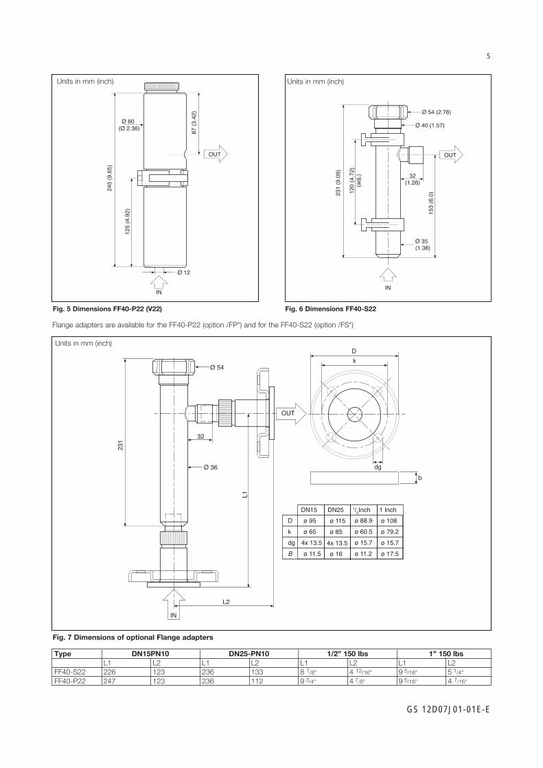
Fig. 5 Dimensions FF40-P22 (V22) Fig. 6 Dimensions FF40-S22
Flange adapters are available for the FF40-P22 (option /FP*) and for the FF40-S22 (option /FS*)
L1
Ø 36
Ø 54
32
231
IN
OUT
L2
bdg
kD
DN15 DN25 1/2Inch 1 InchDkdgB
ø 95ø 65
4x 13.5ø 11.5
ø 115 ø 85
ø 16
ø 88.9ø 60.5ø 15.7ø 11.2
ø 108 ø 79.2ø 15.7ø 17.5
4x 13.5
Units in mm (inch)
Ø 35(1.38)
Ø 54 (2.76)
32(1.26)
IN
Ø 40 (1.57)
120
(4.7
2)(a
dj.)
153
(6.0
)231
(9.0
9)
IN
OUT
245
(9.6
5)
Ø 60(Ø 2.36)
125
(4.9
2)
87 (3
.42)
Ø 12
OUT
Fig. 7 Dimensions of optional Flange adapters
Type DN15PN10 DN25-PN10 1/2” 150 lbs 1” 150 lbs L1 L2 L1 L2 L1 L2 L1 L2FF40-S22 226 123 236 133 8 7/8” 4 13/16” 9 5/16” 5 1/4”FF40-P22 247 123 236 112 9 3/4” 4 7/8” 9 5/16” 4 7/16”
Units in mm (inch)
Units in mm (inch)

6
GS 12D07J01-01E-E
Sensor(EP16 model)
FS40-S23-DF
Fig. 8 Installation example of the SC42-EP16 sensor with a FS40-S23-DF subassembly
Modelcode FS40 Subassembly for Flow fitting
Model code Suffix code Option code DescriptionFS40 SubassemblyMaterial - F22 Polyvinylidenefluoride (PVDF) - S22 Stainless steel (AISI 316L) - S23 Stainless steel (AISI 316L) for EP16 model sensor - V22 Polyvinylchloride (PVC)Mounting - WE Weld-in socket for - S22 and - S23 Glue-in socket for - V22 - PA Parallel thread, only for - F22, (ISO 228/1-G11/4”) - TP Tapered pipe thread (11/4” NPT) - DF For insertion type sensor with collar piece
DN25 in combination with - S23Material Certificate /M 3.1 according to EN-10024 for Stainless steel wetted parts

7
GS 12D07J01-01E-E
50 (1
.97)
FS40-S22-TP
Ø 54(2.12)
1 1/4" NPT41 (1
.61)
FS40-V22-TPFS40-F22-TP
61 (2
.40) Ø 55
(2.16)
1 1/4"-11.5NPT
36 (1
.42)
27 (1
.06)
24 (0
.95)
Ø 63(2.48)
FS40-S23-DF
Ø 28(1.10)
Ø 31(1.22)
FS40-S22-WE
Ø 54(2.12)
Ø 38(1.50)
36 (1
.42)
Ø 36(1.42)
27 (1
.06)
52 (2
.05) Ø 55(2.16)
1 1/4" ISO228/1-G 1 1/4
27 (1
.06)
19 (0
.75)
FS40-F22-PA
57 (2
.25) Ø 50
(1.97)32 (1
.26)
24 (0
.95)
Ø 40(1.57)
FS40-V22-WE
Fig. 9 Dimensions FS40 Flow fitting subassemblies
Units in mm (inch)

8
GS 12D07J01-01E-E
Typical installation of SC42 sensor in FD40 Immersion fittingThe immersion fittings are for installing the SC42 sensor in tanks, open vessels or drains. If the fitting is mounted in a tank with agitator or if it is placed in a fast flowing process, care must be taken that the fitting is adequately supported. For this reason several mounting flanges can be ordered.
Modelcode FD40 Immersion fitting Model code Suffix code Option code DescriptionFD40V28 Immersion fitting PVCFD40S28 Immersion fitting Stainless Steel AISI 316LImmersion - Between 05 and 20 decimeter depth (Example 06 = 6 dm. = 0.6 m.) - NC No CableFlange - FN No Flange - F1 PVC flange DN50 PN10 - F2 PVC flange ANSI 2” 150 lbs - F3 Stainless Steel flange DN50 PN10 - F4 Stainless Steel flange ANSI 2” 150 lbsStyle code * B Protection hose /PH5 For 5.5 meter mounting cable /PH10 For 10 meter mounting cableMounting cable /C05 Length 5,5 meter* /C10 Length 10 meter*Material Certificate /M 3.1 according to EN-10024 for SS wetted parts
*Note: If it is necessary to use the fitting with another mounting cable length, this cable can be ordered separately as WU40 model (Amphenol connector) or WU10/WE10 (Variopin connector).
Model code Suffix code DescriptionWU10 Universal sensor cableConn. type -V VariopinCable type -D Dual CoaxCable length -02 2 meters -05 5 meters -10 10 meters -15 15 meters -20 20 meters
Model code Suffix code DescriptionWU40 Sensor cableCable length - LH01 1 meter - LH02 2 meters - LH05 5½ meters - LH10 10 meters - LH15 15 meters - LH20 20 meters - LH25 25 meters
Ø 50
Ø 40
Probe length (L)Min. 490Max. 1990
Sensor lengthminus 5 mm
d
kD
B
Ø 40 (1.57)
Ø 50 (1.97)
90 (3
.54)
L
Ø 100 (3.94)
18 (0.70)d
kD
Sensor lengthminus 5 mm
Flange D k d BDN50 165 125 18 182”150 lbs 152.4 120.7 19.1 19.1 (6”) (4.75”) (0.75”)
PVCUnits in mm (inch)
Flange D k dNW50 165 125 182”150 lbs 152.4 120.7 19.1 (6”) (4.75”) (0.75”)
SS
FD40V28FD40S28
Figure 10 Figure 11
Units in mm (inch)

9
GS 12D07J01-01E-E
1.0226
8.94227
291.
14
301.
18
301.
18 46
1.8
291.16
100.39
1947.64
10.46266
*
7.76197
120.47 57
2.24
1646.46
10
0.39
30
9.28235.6
1.18
*
5.67144
301.
18
572.24
182.6
120.47
1114.37
301.
18
7.19
0.3910
*
SC42-FV08
SC42-SV34
SC42-SV24
SC42-TV08
- * = Minimum submersion depth.- Dimensions in millimeters [Inches].
Fig. 12 Dimensions SC42-SP
ø 36
2010
L
ø 30
1256
SC42-SP34 (L=164 mm)SC42-SP24 (L=111 mm)
Dimensions SC42 sensors.
SC42-SV34 (L=164 mm)SC42-SV24 (L=111 mm)
Fig. 13 Dimensions SC42-SV
Units in mm Units in mm [inch]

10
GS 12D07J01-01E-E
1.0226
8.94227
291.14
301.18
301.18
461.8
291.16
100.39
1947.64
10.46266
*
SC42-FV08SC42-TV08
- * = Minimum submersion depth.- Dimensions in millimeters [Inches].
Fig. 14 Dimensions SC4 -FP/TP
Fig. 16 SC42-EP15 Fig. 17 SC42-EP16
ø 25
15
ø 36
2010
100
12D7J1-15INSERTION SENSORS
SC4.-EP15
Fig. 18 SC42-EP14 (EP18), SC42-EP04 (EP08)
12D7J1-16INSERTION SENSORS
SC4.-EP15D
ø 25
15
65
ø 44
2010
ø 30(1.18")
ø 36(1.42") 10
(0.4
0")
L20
(0.7
8")
30(1
.18"
)43
(1.6
9")
ø dSC42-EP04 (L= 193 mm)SC42-EP14 (L= 160 mm)SC42-EP08 (L= 193 mm)SC42-EP18 (L= 160 mm)
ø 29(1.14")
26(1
.02"
)
ø 36(1.42")
10(0
.40"
) 1
9420
(0.7
8")
46(1
.81"
)30
(1.1
8")
ø 5(0.20")
SC42-FP08SC42-TP08
SC42-FV08SC42-TV08
Fig. 15 Dimensions SC4 -FV/TV
Units in mm (inch)
Units in mm Units in mm Units in mm (inch)
Units in mm [inch]

11
GS 12D07J01-01E-E
Wiring SC42 sensorsThe SC42 sensors are provided with a fixed connector. The standard cable used to connect the sensor with Amphenol connector to the analyser is the WU40. The standard cable used to connect the sensor with VP connector to the analyzer is the WU10. These cables are available up to 25/20 meters. When a longer cable run is necessary (maximum cable run is 60 meters), this can be done by using the WF10 extension cable in combination with the BA10 connection box.
1112
1315
16
14CELLtemp.element
Fig. 19 Top view connector system SC42 2-electrode Fig. 20 Top view connector system SC42 4-electrode
1112
1315
16
14temp.element
CELL
3.5 Modelcode SC42
Model Suffix Code Option code DescriptionSC42** Conductivity Sensor 2- or 4- electrodes + Pt1000Materials -E Epoxy / graphite -S Stainless steel AISI 316L / PEEK -F PVDF / Glass / Platinum -T PTFE / Glass / PlatinumMounting P Plug-in type, plug-socket connector V Plug-in type, VarioPin connector with SENCOM ID-chip*Cell constant 0 C = 10 cm-1 1 C = 1 cm-1 2 C = 0,1 cm-1 3 C = 0,01 cm-1Type 4 2-electrode, flow cell 5 2-electrode, insertion cell 6 2-electrode, insertion cell with DN25 collar 8 4-electrode, flow cellOptions N/A*Note: Suffix V not ATEX/IECEx certified. Suffix V not in combination with suffix -E (Epoxy).**Note: 3.1 Material certificate according to EN 10024 is standard delivered with this sensor.
Amphenol connector
Variopin connector
Amphenol connector
Variopin connector
GS 12D07J01-01E-ESubject to change without notice Printed in The Netherlands, 18-1905Copyright©
YOKOGAWA EUROPE B.V.Euroweg 23825 HD AMERSFOORTThe NetherlandsTel. +31-88-4641 000Fax +31-88-4641 111E-mail: [email protected]/eu
YOKOGAWA CORPORATION OF AMERICA2 Dart RoadNewnan GA 30265United StatesTel. (1)-770-253-7000Fax (1)-770-251-2088www.yokogawa.com/us
YOKOGAWA ELECTRIC ASIA Pte. Ltd.5 Bedok South RoadSingapore 469270SingaporeTel. (65)-241-9933Fax (65)-241-2606www.yokogawa.com/sg
YOKOGAWA HEADQUARTERS9-32, Nakacho 2-chome,MusashinoshiTokyo 180JapanTel. (81)-422-52-5535Fax (81)-422-55-1202www.yokogawa.com
Yokogawa has an extensive sales and distribution network. Please refer to the European website (www.yokogawa.com/eu) to contact your nearest representative.