general information thermal response test - geopass · thermal conductivity ... ples is that the...
TRANSCRIPT
Thermal Response Test
General aspects
The Thermal Response Test is a suit -able method to determine the thermalcharacteristics such as the effectivethermal conductivity (λ) of subsurfacelayers and the thermal resistance ofthe borehole Rb. A knowledge of un-derground thermal properties is requi-red for correct design of borehole heatexchangers (BHE, closed loop system)for heating and cooling of buildings.The most important parameter is thethermal conductivity of the ground andindicates its ability to conduct heat.Thermal conductivity is measured inwatts per Kelvin per metre [W/(m·K)].This parameter is site-specific andcan not be influenced by engineering.
During the TRT a fluid circulating in aborehole withdraws a constant heatcapacity from the formation – or feedsa constant heat capacity to it – over adefined period of time. The tempera-ture changes of the fluid are recordedduring this process and then analysedfor an integral of the thermal conducti-vity of the formation in the immediateborehole vicinity and a thermal resis -tance of the borehole Rb.
The goal of the test is to achievequasi-stationary conditions in the sub-surface heat flow and to continuously
General Information
measure the in- and out-flow tempera-tures of a test plant. The advantageswith the TRT testing in comparison tolaboratory investigations on core sam-ples is that the measurement is carriedout at quasi undisturbed subsoil con-ditions across the entire boreholelength. The pilot drilling with a geo-thermal probe is available for use afterthe end of the TRT. When the quasi-stationary state is reached, the effec-tive thermal conductivity can be cal- culated according to the line source theory.
Thermal Response Test
Common for most Thermal Respon-se Test rigs is that the apparatus in-jects or extracts heat into or from theborehole by circulating a heated orcooled fluid through the borehole heatexchanger. Equipments with a heatedcircu-lation fluid are more common.The temperature response is then measured and used to determine theground thermal properties necessaryto design a BHE system.
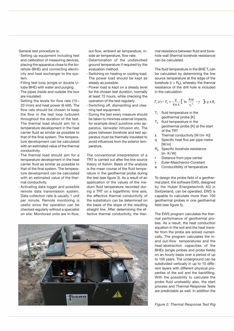
The test rigs contain everything need-ed to perform the test (instrumen -tation, circulation pump, purge tank,electric heater and data logging unit)(see figure 2).
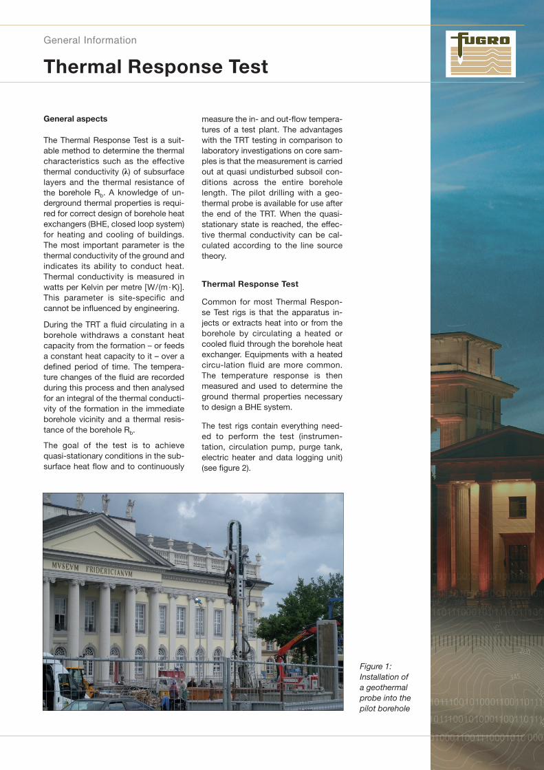
Figure 1: Installation of a geothermalprobe into thepilot borehole
General test procedure is:· Setting up equipment including testand calibration of measuring devices,placing the apparatus close to the bo-rehole (BHE) and connecting electri-city and heat exchanger to the sys-tem.
· Filling test loop (single or double U-tube BHE) with water and purging.
· The pipes inside and outside the boxare insulated.
· Setting the levels for flow rate (10–20 l/min) and heat power (6 kW). Theflow rate should be chosen to keepthe flow in the test loop turbulentthroughout the duration of the test.The thermal load should aim for atemperature development in the heatcarrier fluid as similar as possible tothat of the final system. The tempera-ture development can be calculatedwith an estimated value of the thermalconductivity.
· The thermal load should aim for atemperature development in the heatcarrier fluid as similar as possible tothat of the final system. The tempera-ture development can be calculatedwith an estimated value of the ther-mal conductivity.
· Activating data logger and possibleremote data transmission system.Data collection rate is usually 1 unitper minute. Remote monitoring is useful since the operation can bechecked regularly without a specialiston site. Monitored units are in-flow,
out flow, ambient air temperature, in-side air temperature, flow rate.
· Determination of the undisturbedground temperature if required by theevaluation method.
· Switching on heating or cooling load.The power load should be kept assteady as possible.
· Power load is kept on a steady levelfor the chosen test duration, normallyat least 72 hours, while checking theoperation of the test regularly.
· Switching off, dismantling and clea-ning test equipment.
· During the test every measure shouldbe taken to minimise external impacts,for example direct sunshine onto ap-paratus, rainwater intrusion etc. Thepipes between borehole and test ap-paratus must be thermally insulated toavoid influences from the exterior tem-perature.
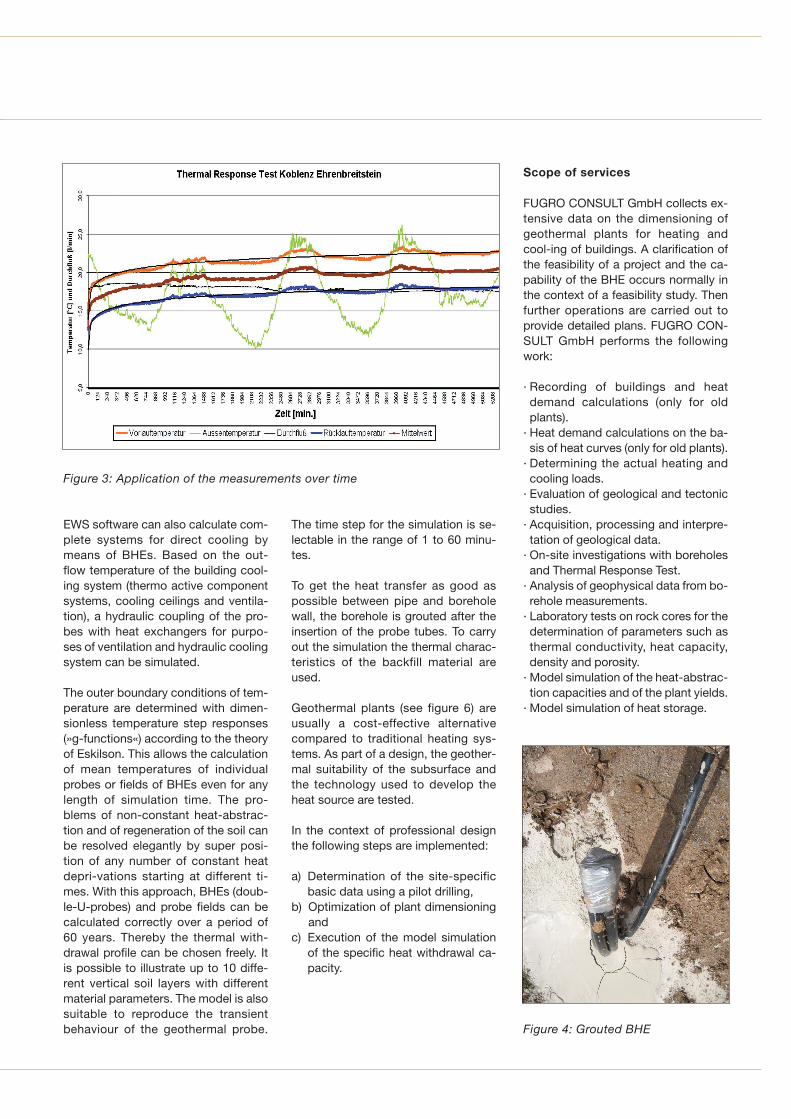
The conventional interpretation of aTRT is carried out after the line sourcetheory of Kelvin. Basis of the analysisis the mean course of the fluid tempe-rature in the geothermal probe duringthe test (see figure 3). As a result of anapplication of the values of the me-dium fluid temperature recorded dur -ing a TRT on a logarithmic time axis,the effective thermal conductivity ofthe substratum can be determined onthe basis of the slope of the resultingstraight line. After determining the ef-fective thermal conductivity, the ther-
mal resistance between fluid and bore-hole wall (thermal borehole resistance)can be calculated.
The fluid temperature in the BHE Tf canbe calculated by determining the linesource temperature at the edge of theborehole (r = Rb), whereby the thermalresistance of the drill hole is includedin the calculation:
Tf fluid temperature in the geothermal probe [K]
T0 fluid temperature in the geothermal probe [K] at the startof the TRT
λ Thermal conductivity [W/ (m· K)]q Specific heat flux per pipe metre
[W/m]Rb Specific borehole resistance
[m· K/W]r Distance from pipe center γ Euler-Mascheroni-Constantα Conductibility of temperature
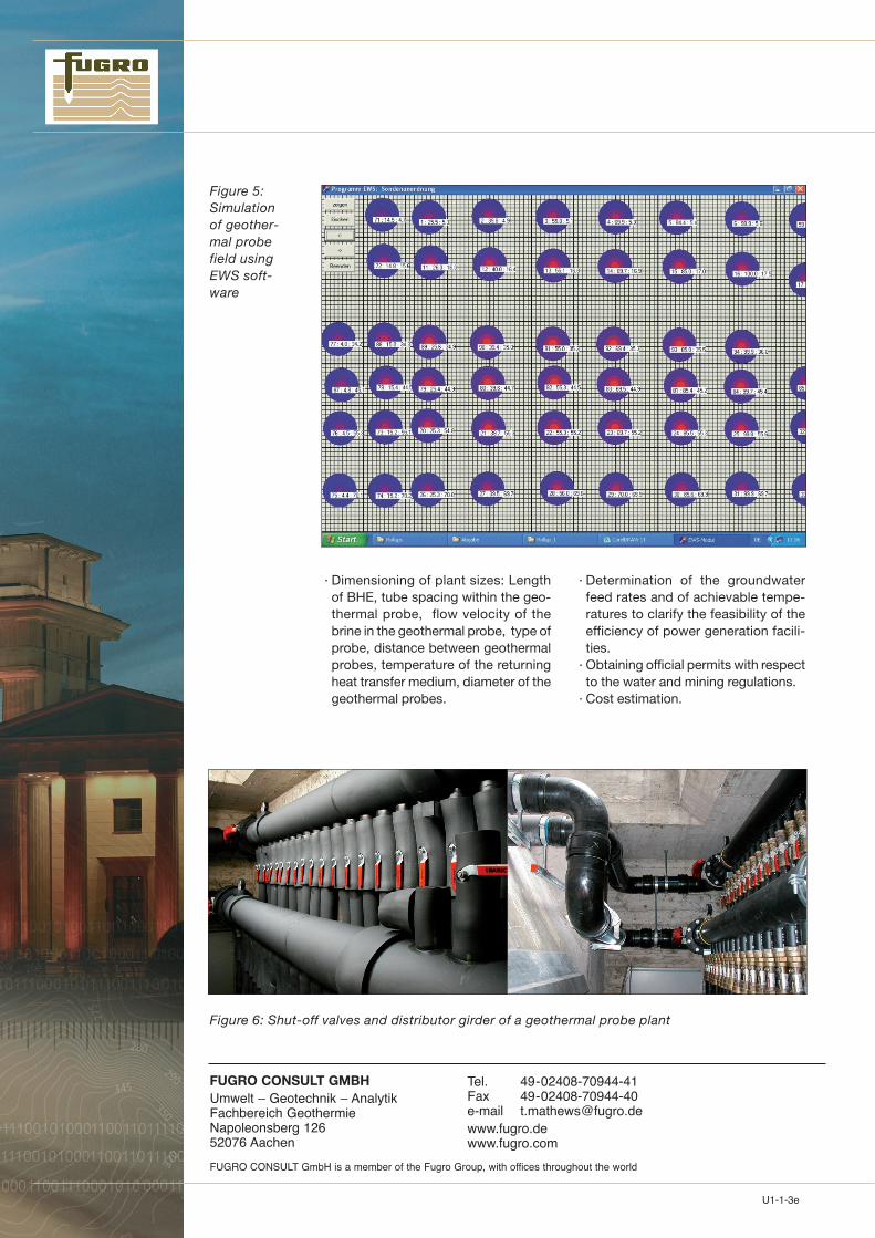
To design the probe field of a geother-mal plant, the software EWS, designedby the Huber Energietechnik AG inSwitzerland, can be operated. EWS iscapable to calculate more than 100geothermal probes in one geothermalfield (see figure 5).
The EWS program calculates the ther-mal performance of geothermal pro-bes. As a result, the heat conductionequation in the soil and the heat trans-fer from the probe are solved numeri-cally. The program calculates the in-and out-flow temperatures and theheat-abstraction capacities of theBHEs (single probes and probe fields)on an hourly basis over a period of upto 100 years. The underground can besubdivided vertically in up to 10 diffe-rent layers with different physical pro-perties of the soil and the backfilling.With the possibility to calculate theprobe fluid unsteadily also, the startprocess and Thermal-Response Testsare predictable as well. In addition the
Figure 2: Thermal Response Test Rig
EWS software can also calculate com-plete systems for direct cooling by means of BHEs. Based on the out-flow temperature of the building cool -ing system (thermo active componentsystems, cooling ceilings and ventila-tion), a hydraulic coupling of the pro-bes with heat exchangers for purpo-ses of ventilation and hydraulic coolingsystem can be simulated.
The outer boundary conditions of tem-perature are determined with dimen-sionless temperature step responses(»g-functions«) according to the theoryof Eskilson. This allows the calculationof mean temperatures of individualprobes or fields of BHEs even for anylength of simulation time. The pro-blems of non-constant heat-abstrac-tion and of regeneration of the soil canbe resolved elegantly by super posi-tion of any number of constant heatdepri-vations starting at different ti-mes. With this approach, BHEs (doub -le-U-probes) and probe fields can becalculated correctly over a period of60 years. Thereby the thermal with -drawal profile can be chosen freely. Itis possible to illustrate up to 10 diffe-rent vertical soil layers with differentmaterial parameters. The model is alsosuitable to reproduce the transient behaviour of the geothermal probe.
The time step for the simulation is se-lectable in the range of 1 to 60 minu-tes.
To get the heat transfer as good aspossible between pipe and boreholewall, the borehole is grouted after theinsertion of the probe tubes. To carryout the simulation the thermal charac-teristics of the backfill material areused.
Geothermal plants (see figure 6) areusually a cost-effective alternativecompared to traditional heating sys-tems. As part of a design, the geother-mal suitability of the subsurface andthe technology used to develop theheat source are tested.
In the context of professional designthe following steps are implemented:
a) Determination of the site-specificbasic data using a pilot drilling,
b) Optimization of plant dimensioningand
c) Execution of the model simulationof the specific heat withdrawal ca-pacity.
Scope of services
FUGRO CONSULT GmbH collects ex-tensive data on the dimensioning ofgeothermal plants for heating andcool-ing of buildings. A clarification ofthe feasibility of a project and the ca-pability of the BHE occurs normally inthe context of a feasibility study. Thenfurther operations are carried out toprovide detailed plans. FUGRO CON-SULT GmbH performs the followingwork:
· Recording of buildings and heat demand calculations (only for oldplants).
· Heat demand calculations on the ba-sis of heat curves (only for old plants).
· Determining the actual heating andcooling loads.
· Evaluation of geological and tectonicstudies.
· Acquisition, processing and interpre-tation of geological data.
· On-site investigations with bore holesand Thermal Response Test.
· Analysis of geophysical data from bo-rehole measurements.
· Laboratory tests on rock cores for thedetermination of parameters such asthermal conductivity, heat capacity,density and porosity.
· Model simulation of the heat-abstrac-tion capacities and of the plant yields.
· Model simulation of heat storage.
Figure 3: Application of the measurements over time
Figure 4: Grouted BHE
U1-1-3e
FUGRO CONSULT GMBHUmwelt – Geotechnik – AnalytikFachbereich GeothermieNapoleonsberg 12652076 Aachen
Tel. 49-02408-70944-41Fax 49-02408-70944-40e-mail [email protected]
FUGRO CONSULT GmbH is a member of the Fugro Group, with offices throughout the world
· Dimensioning of plant sizes: Lengthof BHE, tube spacing within the geo-thermal probe, flow velocity of thebrine in the geothermal probe, type ofprobe, distance between geothermalprobes, temperature of the returningheat transfer medium, diameter of thegeothermal probes.
· Determination of the groundwaterfeed rates and of achievable tempe-ratures to clarify the feasibility of theefficiency of power generation facili-ties.
· Obtaining official permits with respectto the water and mining regulations.
· Cost estimation.
Figure 5: Simulation of geother-mal probefield usingEWS soft-ware
Figure 6: Shut-off valves and distributor girder of a geothermal probe plant