general catalog - heidenhain.com.br · dr. johannes heidenhain gmbh develops and manufactures...
TRANSCRIPT
General CatalogLinear EncodersLength GaugesAngle EncodersRotary EncodersContouring ControlsTouch ProbesEvaluation ElectronicsDigital Readouts
09/2018
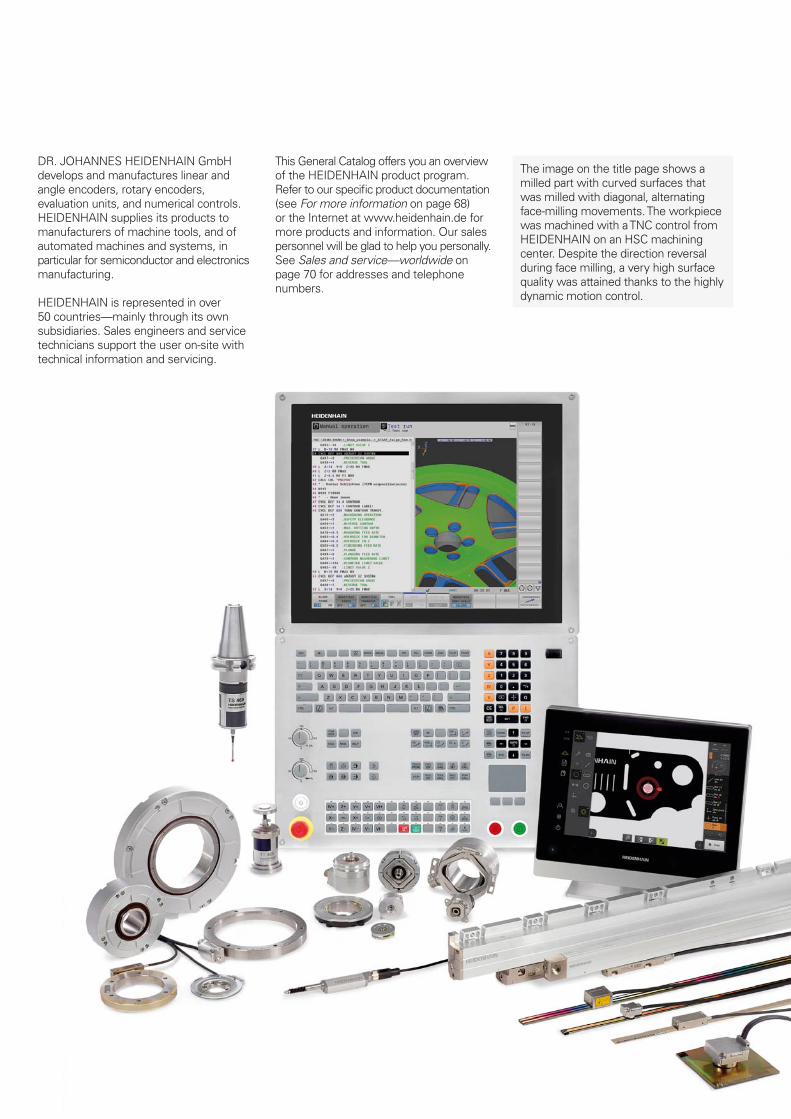
DR. JOHANNES HEIDENHAIN GmbH develops and manufactures linear and angle encoders, rotary encoders, evaluation units, and numerical controls. HEIDENHAIN supplies its products to manufacturers of machine tools, and of automated machines and systems, in particular for semiconductor and electronics manufacturing.
HEIDENHAIN is represented in over 50 countries—mainly through its own subsidiaries. Sales engineers and service technicians support the user on-site with technical information and servicing.
This General Catalog offers you an overview of the HEIDENHAIN product program. Refer to our specifi c product documentation (see For more information on page 68) or the Internet at www.heidenhain.de for more products and information. Our sales personnel will be glad to help you personally. See Sales and service—worldwide on page 70 for addresses and telephone numbers.
The image on the title page shows a milled part with curved surfaces that was milled with diagonal, alternating face-milling movements. The workpiece was machined with a TNC control from HEIDENHAIN on an HSC machining center. Despite the direction reversal during face milling, a very high surface quality was attained thanks to the highly dynamic motion control.
Contents
Fundamentals and processes 4
Precision graduations—the foundation for high accuracy 5
Length measurement 6
Sealed linear encoders
Exposed linear encoders
Length gauges
Angle measurement 18
Sealed angle encoders
Angle encoder modules
Modular angle encoders
Rotary encoders
Machine tool control 42
Straight-cut control for milling machines
Contouring controls for milling machines and machining centers
Contouring controls for milling-turning machines and machining centers
Contouring controls for lathes
Programming stations
Tool and workpiece setup and measurement 56
Workpiece touch probes
Tool touch probes
Measured value acquisition and display 60
Evaluation electronics for metrology applications
Digital readouts for manually operated machine tools
Interface electronics
For more information 68
Sales and service 70
4
Fundamentals and processes
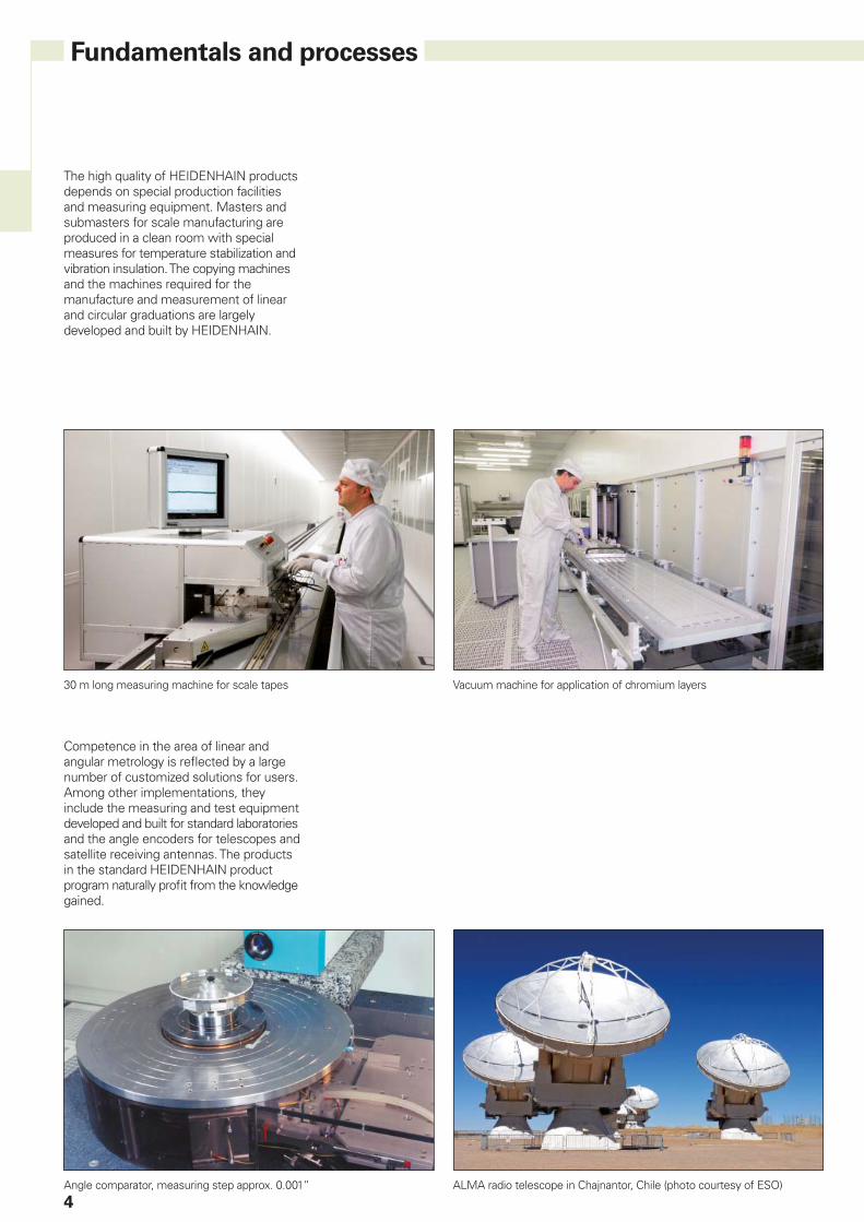
The high quality of HEIDENHAIN products depends on special production facilities and measuring equipment. Masters and submasters for scale manufacturing are produced in a clean room with special measures for temperature stabilization and vibration insulation. The copying machines and the machines required for the manufacture and measurement of linear and circular graduations are largely developed and built by HEIDENHAIN.
Competence in the area of linear and angular metrology is refl ected by a large number of customized solutions for users. Among other implementations, they include the measuring and test equipment developed and built for standard laboratories and the angle encoders for telescopes and satellite receiving antennas. The products in the standard HEIDENHAIN product program naturally profi t from the knowledge gained.
30 m long measuring machine for scale tapes Vacuum machine for application of chromium layers
Angle comparator, measuring step approx. 0.001” ALMA radio telescope in Chajnantor, Chile (photo courtesy of ESO)
5
Precision graduations—the foundation for high accuracy
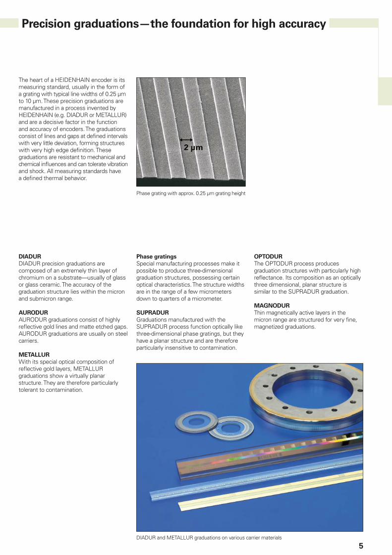
The heart of a HEIDENHAIN encoder is its measuring standard, usually in the form of a grating with typical line widths of 0.25 µm to 10 µm. These precision graduations are manufactured in a process invented by HEIDENHAIN (e.g. DIADUR or METALLUR) and are a decisive factor in the function and accuracy of encoders. The graduations consist of lines and gaps at defi ned intervals with very little deviation, forming structures with very high edge defi nition. These graduations are resistant to mechanical and chemical infl uences and can tolerate vibration and shock. All measuring standards have a defi ned thermal behavior.
Phase grating with approx. 0.25 µm grating height
DIADUR
DIADUR precision graduations are composed of an extremely thin layer of chromium on a substrate—usually of glass or glass ceramic. The accuracy of the graduation structure lies within the micron and submicron range.
AURODUR
AURODUR graduations consist of highly refl ective gold lines and matte etched gaps. AURODUR graduations are usually on steel carriers.
METALLUR
With its special optical composition of refl ective gold layers, METALLUR graduations show a virtually planar structure. They are therefore particularly tolerant to contamination.
Phase gratings
Special manufacturing processes make it possible to produce three-dimensional graduation structures, possessing certain optical characteristics. The structure widths are in the range of a few micrometers down to quarters of a micrometer.
SUPRADUR
Graduations manufactured with the SUPRADUR process function optically like three-dimensional phase gratings, but they have a planar structure and are therefore particularly insensitive to contamination.
OPTODUR
The OPTODUR process produces graduation structures with particularly high refl ectance. Its composition as an optically three dimensional, planar structure is similar to the SUPRADUR graduation.
MAGNODUR
Thin magnetically active layers in the micron range are structured for very fi ne, magnetized graduations.
DIADUR and METALLUR graduations on various carrier materials
6
Length measurement
Sealed linear encoders are available with• Full-size scale housing
– For high vibration loading– Up to 30 m measuring length
(72 m upon request)• Slimline scale housing
– For limited installation space– Measuring length up to 2040 mm
(for measuring lengths starting from 1240 mm, mounting via mounting spar or tensioning elements)
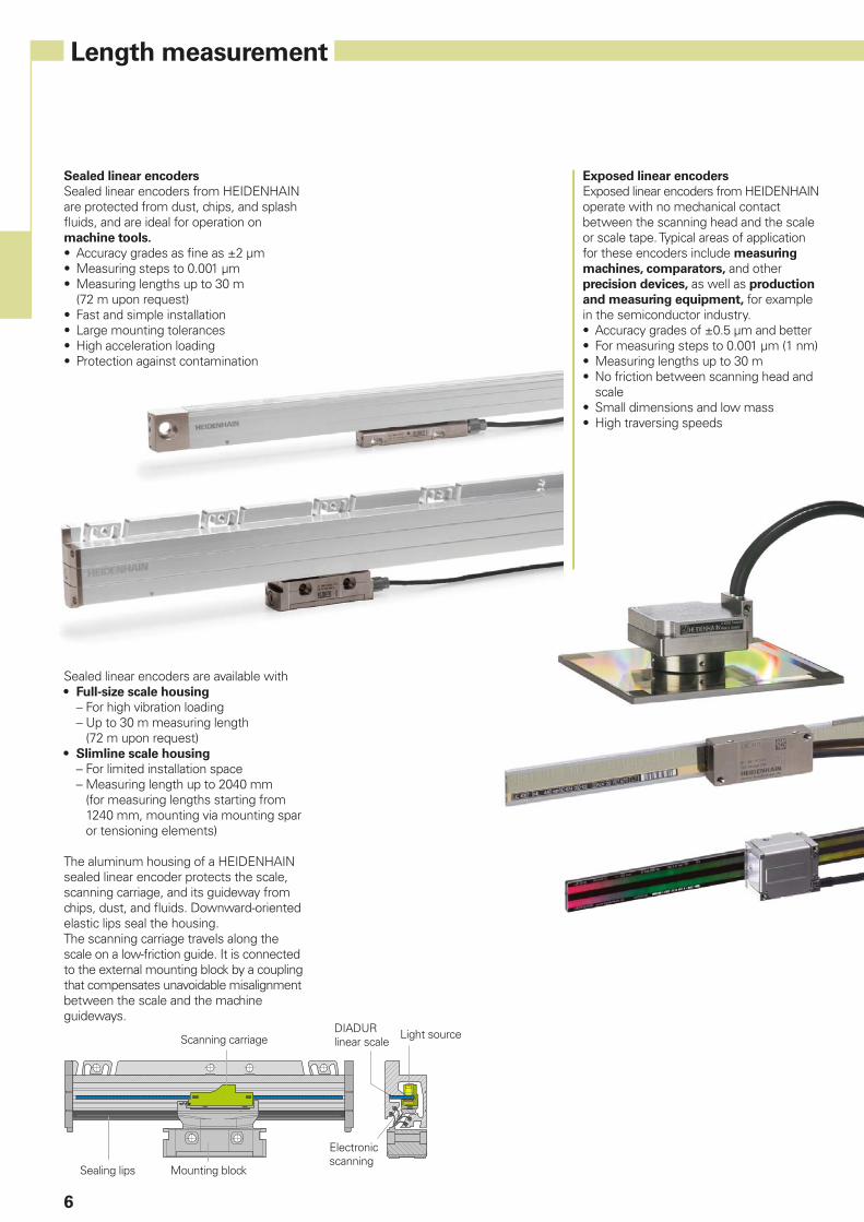
The aluminum housing of a HEIDENHAIN sealed linear encoder protects the scale, scanning carriage, and its guideway from chips, dust, and fl uids. Downward-oriented elastic lips seal the housing.The scanning carriage travels along the scale on a low-friction guide. It is connected to the external mounting block by a coupling that compensates unavoidable misalignment between the scale and the machine guideways.
Scanning carriageDIADUR linear scale
Light source
Sealing lips Mounting block
Electronic scanning
Exposed linear encoders
Exposed linear encoders from HEIDENHAIN operate with no mechanical contact between the scanning head and the scale or scale tape. Typical areas of application for these encoders include measuring
machines, comparators, and other precision devices, as well as production
and measuring equipment, for example in the semiconductor industry.• Accuracy grades of ±0.5 µm and better• For measuring steps to 0.001 µm (1 nm)• Measuring lengths up to 30 m• No friction between scanning head and
scale• Small dimensions and low mass• High traversing speeds
Sealed linear encoders
Sealed linear encoders from HEIDENHAIN are protected from dust, chips, and splash fl uids, and are ideal for operation on machine tools.
• Accuracy grades as fi ne as ±2 µm• Measuring steps to 0.001 µm• Measuring lengths up to 30 m
(72 m upon request)• Fast and simple installation• Large mounting tolerances• High acceleration loading• Protection against contamination
7
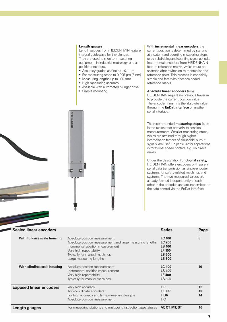
Length gauges
Length gauges from HEIDENHAIN feature integral guideways for the plunger.They are used to monitor measuring equipment, in industrial metrology, and as position encoders.• Accuracy grades as fi ne as ±0.1 µm• For measuring steps to 0.005 µm (5 nm)• Measuring lengths up to 100 mm• High measuring accuracy• Available with automated plunger drive• Simple mounting
With incremental linear encoders the current position is determined by starting at a datum and counting measuring steps, or by subdividing and counting signal periods. Incremental encoders from HEIDENHAIN feature reference marks, which must be scanned after switch-on to reestablish the reference point. This process is especially simple and fast with distance-coded reference marks.
Absolute linear encoders from HEIDENHAIN require no previous traverse to provide the current position value.The encoder transmits the absolute value through the EnDat interface or another serial interface.
The recommended measuring steps listed in the tables refer primarily to position measurements. Smaller measuring steps, which are attained through higher interpolation factors of sinusoidal output signals, are useful in particular for applications in rotational speed control, e.g. on direct drives.
Under the designation functional safety, HEIDENHAIN offers encoders with purely serial data transmission as single-encoder systems for safety-related machines and systems. The two measured values are already formed independently of each other in the encoder, and are transmitted to the safe control via the EnDat interface.
Sealed linear encoders Series Page
With full-size scale housing Absolute position measurementAbsolute position measurement and large measuring lengthsIncremental position measurementVery high repeatabilityTypically for manual machinesLarge measuring lengths
LC 100
LC 200
LS 100
LF 100
LS 600
LB 300
8
With slimline scale housing Absolute position measurementIncremental position measurementVery high repeatabilityTypically for manual machines
LC 400
LS 400
LF 400
LS 300
10
Exposed linear encoders Very high accuracyTwo-coordinate encodersFor high accuracy and large measuring lengthsAbsolute position measurement
LIP
LIF, PP
LIDA
LIC
12
13
14
Length gauges For measuring stations and multipoint inspection apparatuses AT, CT, MT, ST 16
8
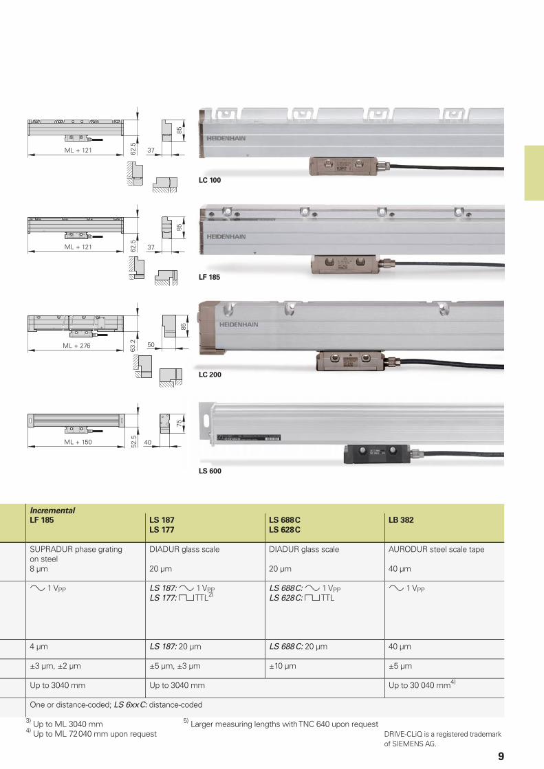
LC, LF, LS, LB sealed linear encoders
With full-size scale housing
Linear encoders with full-size scale
housing are characterized particularly by their high tolerance to vibration.
Absolute linear encoders of the LC 100 and LC 200 series provide the absolute
position value without requiring any previous traverse. Depending on the version, incremental signals can be output additionally. The LC 100 can be mounted to the same mating dimensions as the incremental linear encoders of the LS 100 series, and feature the same mechanical design. Because of their high accuracy and defi ned thermal behavior, LC 100 and LS 100 series linear encoders are especially well suited for use on numerically
controlled machine tools.
The incremental encoders of the LF type feature measuring standards with relatively fi ne grating periods. This makes them particularly attractive for applications requiring very high repeatability.
The LS 600 series incremental linear encoders are used for simple positioning tasks, for example on manual machine
tools.
The LC 200 (absolute) and LB (incremental) linear encoders were conceived for very long measuring lengths. Their measuring standard—a steel tape with METALLUR or AURODUR graduation—is delivered as a single piece, and after the housing sections have been mounted, is pulled into the housing, drawn to a defi ned tension and fi xed at both ends to the machine casting.
LF 185
• Very high repeatability
• Thermal behavior similar to steel or cast iron
• High vibration rating• Two mounting attitudes• Single-fi eld scanning
LC 100 series
• Absolute position measurement
• Defi ned thermal behavior• High vibration rating• Two mounting attitudes• Single-fi eld scanning
LS 100 series
• Incremental position measurement
• Defi ned thermal behavior• High vibration rating• Two mounting attitudes• Single-fi eld scanning
LS 600 series
• Typically for manual machines
• Simple installation
LB 382
• For large measuring lengths up to 30 m4)
• Defi ned thermal behavior• High vibration rating• Two mounting attitudes• Single-fi eld scanning
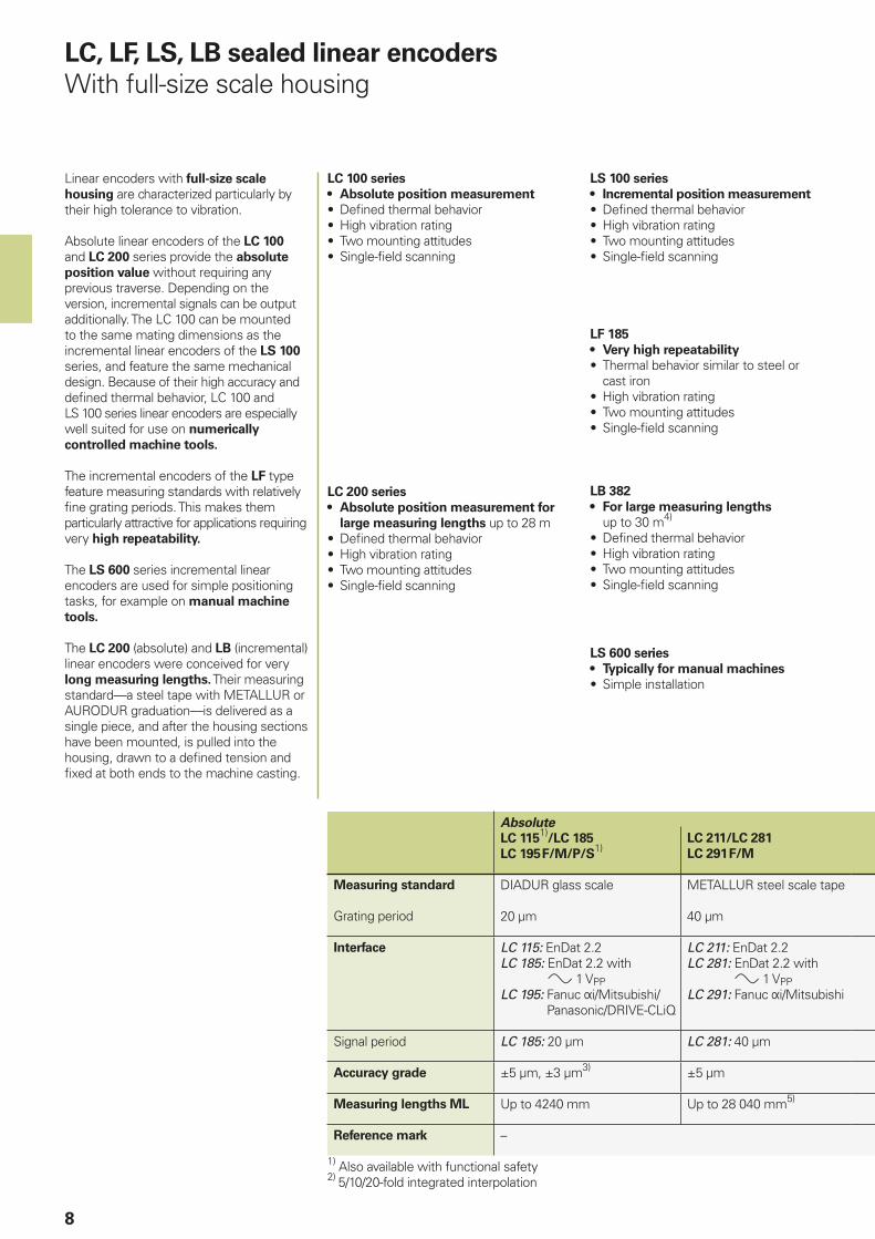
Absolute
LC 1151)
/LC 185
LC 195 F/M/P/S1)
LC 211/LC 281
LC 291 F/M
Measuring standard
Grating period
DIADUR glass scale
20 µm
METALLUR steel scale tape
40 µm
Interface LC 115: EnDat 2.2LC 185: EnDat 2.2 with
1 VPPLC 195: Fanuc i/Mitsubishi/
Panasonic/DRIVE-CLiQ
LC 211: EnDat 2.2LC 281: EnDat 2.2 with
1 VPPLC 291: Fanuc i/Mitsubishi
Signal period LC 185: 20 µm LC 281: 40 µm
Accuracy grade ±5 µm, ±3 µm3) ±5 µm
Measuring lengths ML Up to 4240 mm Up to 28 040 mm5)
Reference mark –
1) Also available with functional safety2) 5/10/20-fold integrated interpolation
LC 200 series
• Absolute position measurement for
large measuring lengths up to 28 m• Defi ned thermal behavior• High vibration rating• Two mounting attitudes• Single-fi eld scanning
LC 100
LF 185
LC 200
LS 600
9
Incremental
LF 185 LS 187
LS 177
LS 688 C
LS 628 C
LB 382
SUPRADUR phase grating on steel8 µm
DIADUR glass scale
20 µm
DIADUR glass scale
20 µm
AURODUR steel scale tape
40 µm
1 VPP LS 187: 1 VPPLS 177: TTL2)
LS 688 C: 1 VPPLS 628 C: TTL
1 VPP
4 µm LS 187: 20 µm LS 688 C: 20 µm 40 µm
±3 µm, ±2 µm ±5 µm, ±3 µm ±10 µm ±5 µm
Up to 3040 mm Up to 3040 mm Up to 30 040 mm4)
One or distance-coded; LS 6xx C: distance-coded
3) Up to ML 3040 mm 5) Larger measuring lengths with TNC 640 upon request4) Up to ML 72 040 mm upon request DRIVE-CLiQ is a registered trademark
of SIEMENS AG.
10
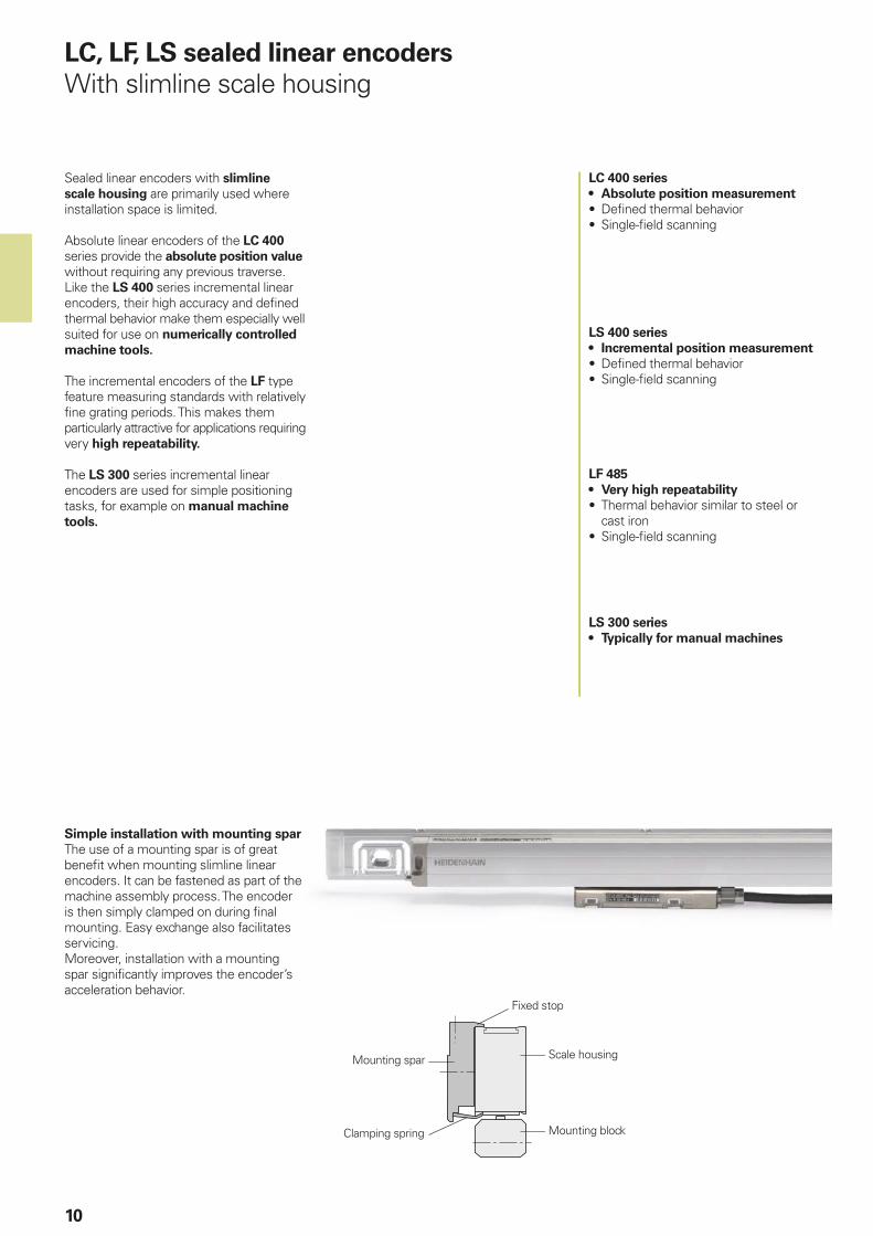
LC, LF, LS sealed linear encoders
With slimline scale housing
Sealed linear encoders with slimline
scale housing are primarily used where installation space is limited.
Absolute linear encoders of the LC 400 series provide the absolute position value without requiring any previous traverse. Like the LS 400 series incremental linear encoders, their high accuracy and defi ned thermal behavior make them especially well suited for use on numerically controlled
machine tools.
The incremental encoders of the LF type feature measuring standards with relatively fi ne grating periods. This makes them particularly attractive for applications requiring very high repeatability.
The LS 300 series incremental linear encoders are used for simple positioning tasks, for example on manual machine
tools.
Simple installation with mounting spar
The use of a mounting spar is of great benefi t when mounting slimline linear encoders. It can be fastened as part of the machine assembly process. The encoder is then simply clamped on during fi nal mounting. Easy exchange also facilitates servicing.Moreover, installation with a mounting spar signifi cantly improves the encoder’s acceleration behavior.
LF 485
• Very high repeatability
• Thermal behavior similar to steel or cast iron
• Single-fi eld scanning
LC 400 series
• Absolute position measurement
• Defi ned thermal behavior• Single-fi eld scanning
LS 400 series
• Incremental position measurement
• Defi ned thermal behavior• Single-fi eld scanning
LS 300 series
• Typically for manual machines
Clamping spring
Scale housing
Mounting block
Mounting spar
Fixed stop
LC 400
LS 400
LF 485
LS 300
11
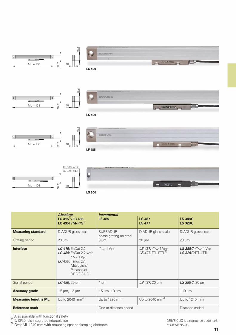
Absolute Incremental
LC 4151)
/LC 485
LC 495 F/M/P/S1)
LF 485 LS 487
LS 477
LS 388 C
LS 328 C
Measuring standard
Grating period
DIADUR glass scale
20 µm
SUPRADUR phase grating on steel8 µm
DIADUR glass scale
20 µm
DIADUR glass scale
20 µm
Interface LC 415: EnDat 2.2LC 485: EnDat 2.2 with
1 VPPLC 495: Fanuc i/
Mitsubishi/Panasonic/DRIVE-CLiQ
1 VPP LS 487: 1 VPPLS 477: TTL2)
LS 388 C: 1 VPPLS 328 C: TTL
Signal period LC 485: 20 µm 4 µm LS 487: 20 µm LS 388 C: 20 µm
Accuracy grade ±5 µm, ±3 µm ±5 µm, ±3 µm ±10 µm
Measuring lengths ML Up to 2040 mm3) Up to 1220 mm Up to 2040 mm3) Up to 1240 mm
Reference mark – One or distance-coded Distance-coded
1) Also available with functional safety2) 5/10/20-fold integrated interpolation3) Over ML 1240 mm with mounting spar or clamping elements
DRIVE-CLiQ is a registered trademark of SIEMENS AG.
12
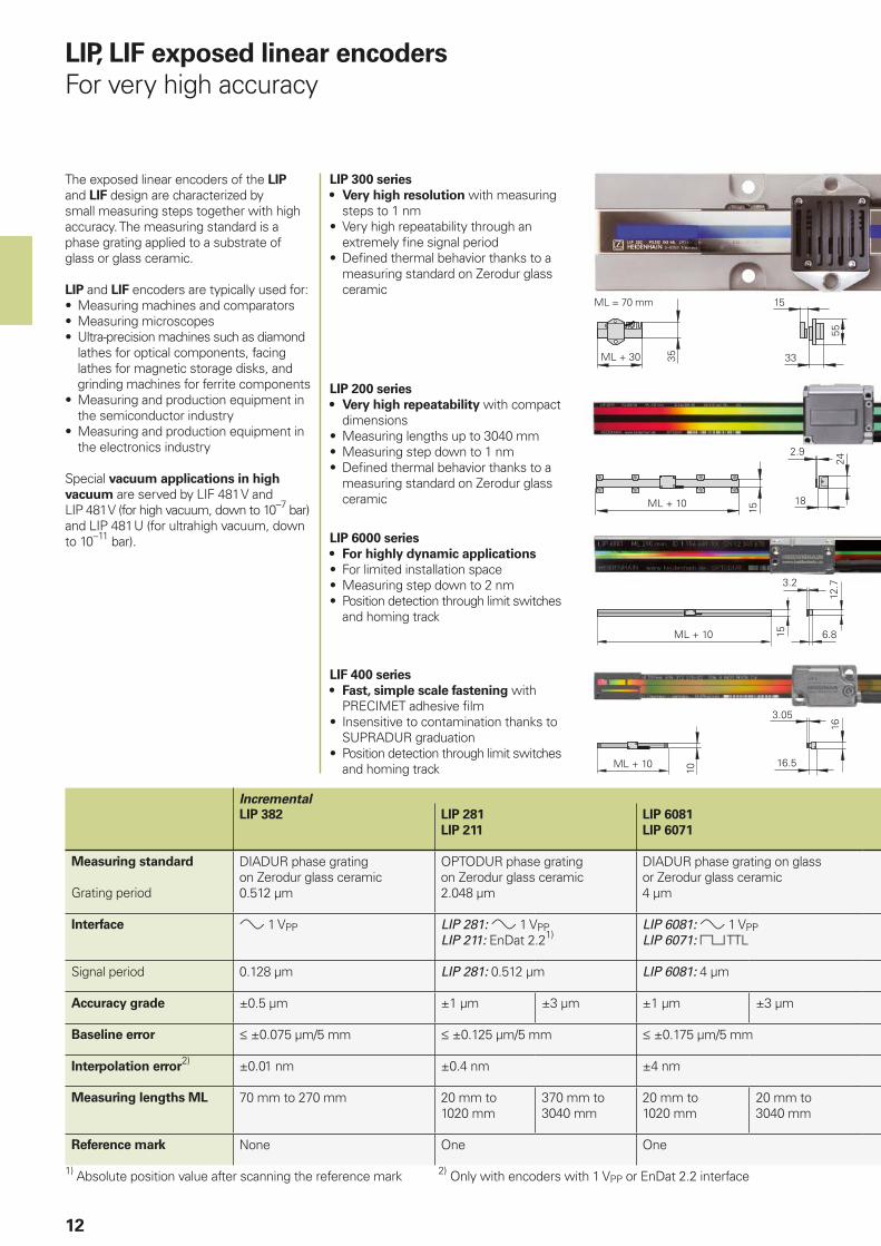
LIP, LIF exposed linear encoders
For very high accuracy
The exposed linear encoders of the LIP and LIF design are characterized by small measuring steps together with high accuracy. The measuring standard is a phase grating applied to a substrate of glass or glass ceramic.
LIP and LIF encoders are typically used for:• Measuring machines and comparators• Measuring microscopes• Ultra-precision machines such as diamond
lathes for optical components, facing lathes for magnetic storage disks, and grinding machines for ferrite components
• Measuring and production equipment in the semiconductor industry
• Measuring and production equipment in the electronics industry
Special vacuum applications in high
vacuum are served by LIF 481 V and LIP 481 V (for high vacuum, down to 10–7 bar) and LIP 481 U (for ultrahigh vacuum, down to 10–11 bar).
LIP 300 series
• Very high resolution with measuring steps to 1 nm
• Very high repeatability through an extremely fi ne signal period
• Defi ned thermal behavior thanks to a measuring standard on Zerodur glass ceramic
LIP 6000 series
• For highly dynamic applications
• For limited installation space• Measuring step down to 2 nm• Position detection through limit switches
and homing track
LIP 200 series
• Very high repeatability with compact dimensions
• Measuring lengths up to 3040 mm• Measuring step down to 1 nm• Defi ned thermal behavior thanks to a
measuring standard on Zerodur glass ceramic
ML = 70 mm
Incremental
LIP 382 LIP 281
LIP 211
LIP 6081
LIP 6071
Measuring standard
Grating period
DIADUR phase grating on Zerodur glass ceramic0.512 µm
OPTODUR phase grating on Zerodur glass ceramic2.048 µm
DIADUR phase grating on glass or Zerodur glass ceramic4 µm
Interface 1 VPP LIP 281: 1 VPPLIP 211: EnDat 2.21)
LIP 6081: 1 VPPLIP 6071: TTL
Signal period 0.128 µm LIP 281: 0.512 µm LIP 6081: 4 µm
Accuracy grade ±0.5 µm ±1 µm ±3 µm ±1 µm ±3 µm
Baseline error ±0.075 µm/5 mm ±0.125 µm/5 mm ±0.175 µm/5 mm
Interpolation error2) ±0.01 nm ±0.4 nm ±4 nm
Measuring lengths ML 70 mm to 270 mm 20 mm to 1020 mm
370 mm to 3040 mm
20 mm to 1020 mm
20 mm to 3040 mm
Reference mark None One One
1) Absolute position value after scanning the reference mark 2) Only with encoders with 1 VPP or EnDat 2.2 interface
LIF 400 series
• Fast, simple scale fastening with PRECIMET adhesive fi lm
• Insensitive to contamination thanks to SUPRADUR graduation
• Position detection through limit switches and homing track
13
LIF 481
LIF 471
SUPRADUR phase grating on glass or Zerodur glass ceramic8 µm
LIF 481: 1 VPPLIF 471: TTL
LIF 481: 4 µm
±1 µm (only Zerodur) ± 3 µm
±0.225 µm/5 mm
±12 nm
70 mm to 1020 mm 70 mm to 1640 mm
One
ML = 120 mm
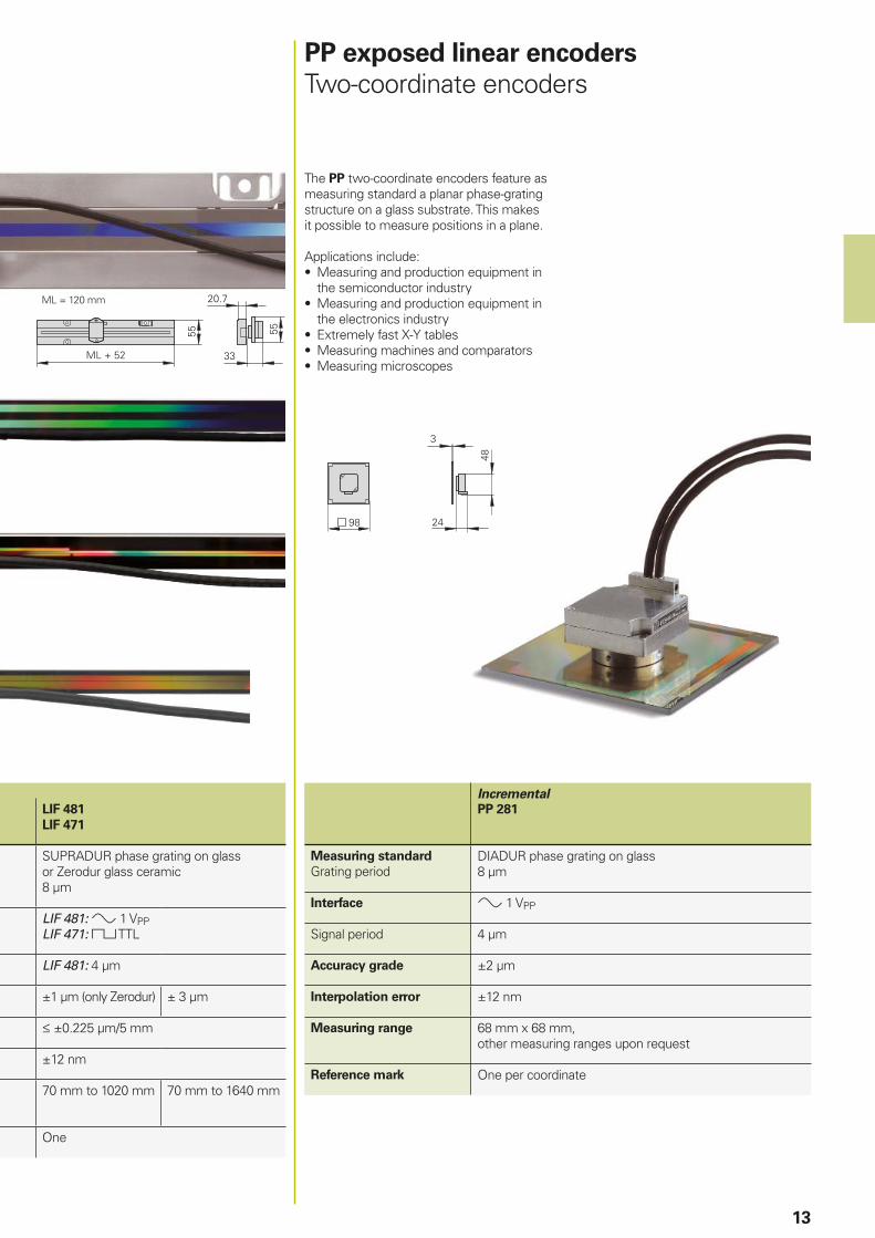
PP exposed linear encoders
Two-coordinate encoders
The PP two-coordinate encoders feature as measuring standard a planar phase-grating structure on a glass substrate. This makes it possible to measure positions in a plane.
Applications include:• Measuring and production equipment in
the semiconductor industry• Measuring and production equipment in
the electronics industry• Extremely fast X-Y tables• Measuring machines and comparators• Measuring microscopes
Incremental
PP 281
Measuring standard
Grating periodDIADUR phase grating on glass8 µm
Interface 1 VPP
Signal period 4 µm
Accuracy grade ±2 µm
Interpolation error ±12 nm
Measuring range 68 mm x 68 mm, other measuring ranges upon request
Reference mark One per coordinate
14
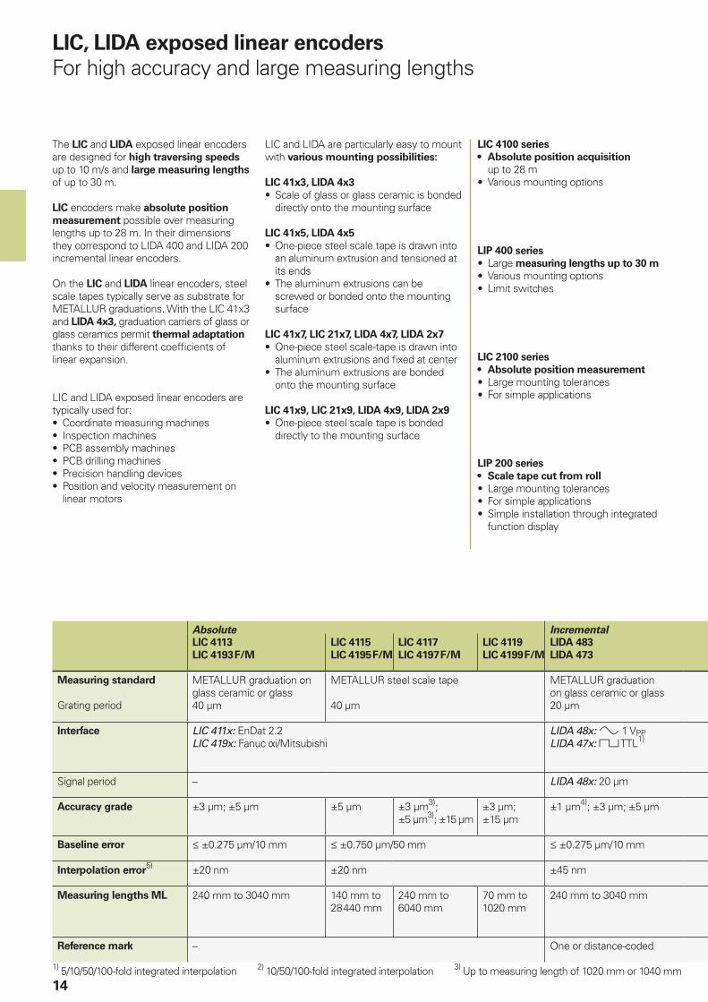
LIC, LIDA exposed linear encoders
For high accuracy and large measuring lengths
The LIC and LIDA exposed linear encoders are designed for high traversing speeds up to 10 m/s and large measuring lengths of up to 30 m.
LIC encoders make absolute position
measurement possible over measuring lengths up to 28 m. In their dimensions they correspond to LIDA 400 and LIDA 200 incremental linear encoders.
On the LIC and LIDA linear encoders, steel scale tapes typically serve as substrate for METALLUR graduations. With the LIC 41x3 and LIDA 4x3, graduation carriers of glass or glass ceramics permit thermal adaptation thanks to their different coeffi cients of linear expansion.
LIC and LIDA exposed linear encoders are typically used for:• Coordinate measuring machines• Inspection machines• PCB assembly machines• PCB drilling machines• Precision handling devices• Position and velocity measurement on
linear motors
LIC 4100 series
• Absolute position acquisition up to 28 m
• Various mounting options
Absolute Incremental
LIC 4113
LIC 4193 F/M
LIC 4115
LIC 4195 F/M
LIC 4117
LIC 4197 F/M
LIC 4119
LIC 4199 F/M
LIDA 483
LIDA 473
Measuring standard
Grating period
METALLUR graduation on glass ceramic or glass40 µm
METALLUR steel scale tape
40 µm
METALLUR graduation on glass ceramic or glass20 µm
Interface LIC 411x: EnDat 2.2LIC 419x: Fanuc i/Mitsubishi
LIDA 48x: 1 VPPLIDA 47x: TTL1)
Signal period – LIDA 48x: 20 µm
Accuracy grade ±3 µm; ±5 µm ±5 µm ±3 µm3); ±5 µm3); ±15 µm
±3 µm; ±15 µm
±1 µm4); ±3 µm; ±5 µm
Baseline error ±0.275 µm/10 mm ±0.750 µm/50 mm ±0.275 µm/10 mm
Interpolation error5) ±20 nm ±20 nm ±45 nm
Measuring lengths ML 240 mm to 3040 mm 140 mm to 28 440 mm
240 mm to 6040 mm
70 mm to 1020 mm
240 mm to 3040 mm
Reference mark – One or distance-coded
1) 5/10/50/100-fold integrated interpolation 2) 10/50/100-fold integrated interpolation 3) Up to measuring length of 1020 mm or 1040 mm
LIC and LIDA are particularly easy to mount with various mounting possibilities:
LIC 41x3, LIDA 4x3
• Scale of glass or glass ceramic is bonded directly onto the mounting surface
LIC 41x5, LIDA 4x5
• One-piece steel scale tape is drawn into an aluminum extrusion and tensioned at its ends
• The aluminum extrusions can be screwed or bonded onto the mounting surface
LIC 41x7, LIC 21x7, LIDA 4x7, LIDA 2x7
• One-piece steel scale-tape is drawn into aluminum extrusions and fi xed at center
• The aluminum extrusions are bonded onto the mounting surface
LIC 41x9, LIC 21x9, LIDA 4x9, LIDA 2x9
• One-piece steel scale tape is bonded directly to the mounting surface
LIP 200 series
• Scale tape cut from roll
• Large mounting tolerances• For simple applications• Simple installation through integrated
function display
LIP 400 series
• Large measuring lengths up to 30 m
• Various mounting options• Limit switches
LIC 2100 series
• Absolute position measurement
• Large mounting tolerances• For simple applications
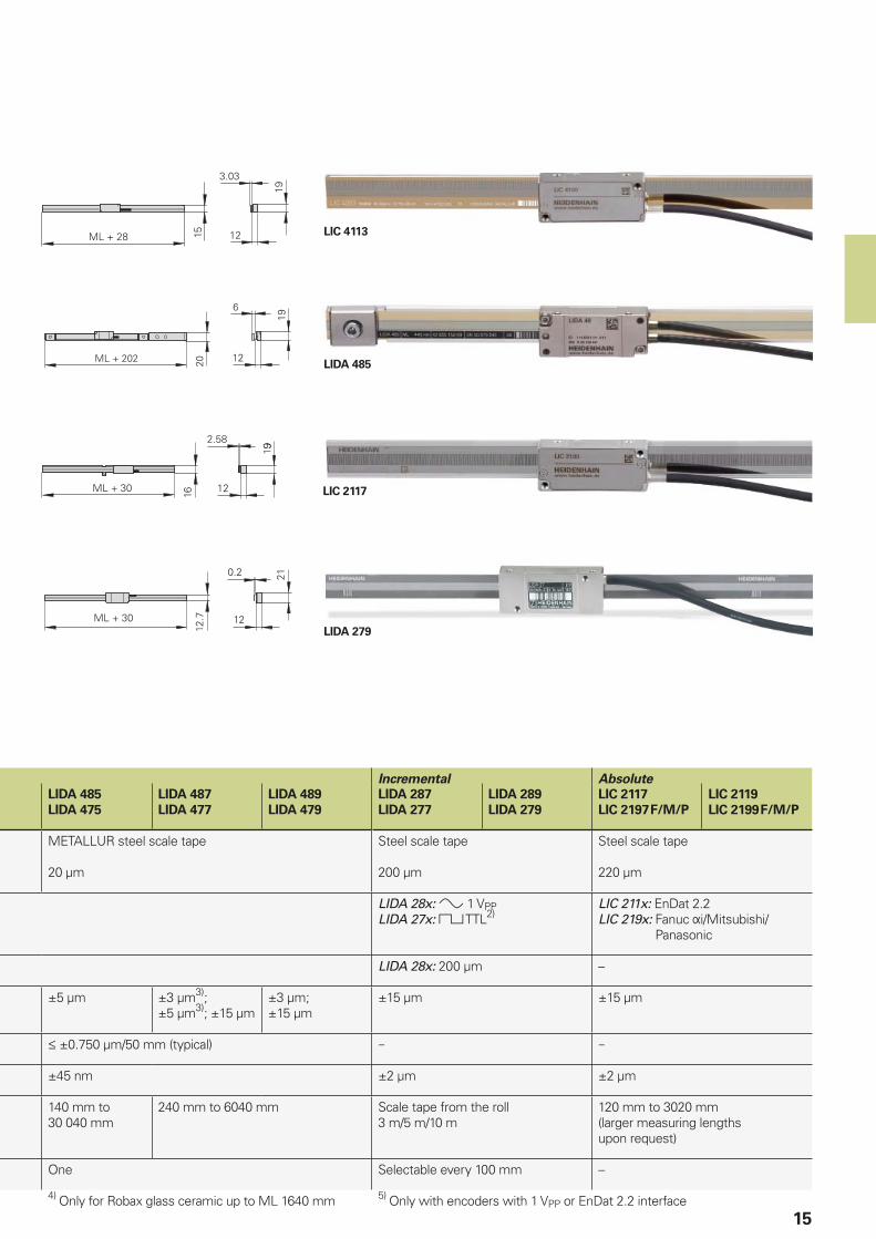
LIDA 279
LIC 4113
LIDA 485
LIC 2117
15
Incremental Absolute
LIDA 485
LIDA 475
LIDA 487
LIDA 477
LIDA 489
LIDA 479
LIDA 287
LIDA 277
LIDA 289
LIDA 279
LIC 2117
LIC 2197 F/M/P
LIC 2119
LIC 2199 F/M/P
METALLUR steel scale tape
20 µm
Steel scale tape
200 µm
Steel scale tape
220 µm
LIDA 28x: 1 VPPLIDA 27x: TTL2)
LIC 211x: EnDat 2.2LIC 219x: Fanuc i/Mitsubishi/
Panasonic
LIDA 28x: 200 µm –
±5 µm ±3 µm3); ±5 µm3); ±15 µm
±3 µm; ±15 µm
±15 µm ±15 µm
±0.750 µm/50 mm (typical) – –
±45 nm ±2 µm ±2 µm
140 mm to 30 040 mm
240 mm to 6040 mm Scale tape from the roll 3 m/5 m/10 m
120 mm to 3020 mm(larger measuring lengths upon request)
One Selectable every 100 mm –
4) Only for Robax glass ceramic up to ML 1640 mm 5) Only with encoders with 1 VPP or EnDat 2.2 interface

16
AT, CT, MT, ST length gauges
For measuring stations and multipoint inspection apparatuses
HEIDENHAIN length gauges are characterized by high accuracy together with large strokes of up to 100 mm. They feature plungers with integral bearings and therefore serve as compact measuring devices.
The HEIDENHAIN-CERTO CT length gauges are used predominantly for production quality control of high-precision parts and for the monitoring and calibration of reference standards.
The HEIDENHAIN-METRO MT 1200 and MT 2500 length gauges are ideal for precision measuring stations and testing equipment. The ball-bush guided plunger tolerates high radial forces. The primary applications for the MT 60 and MT 101 are incoming inspection, production monitoring, and quality control, but also as high-accuracy position encoders, for example on linear slides or X-Y tables.
Thanks to their very small dimensions, the HEIDENHAIN-ACANTO AT and HEIDENHAIN-SPECTO ST series length gauges are the product of choice for multipoint inspection apparatus and testing equipment.
Plunger actuation
The plungers of the length gauges with motorized plunger actuation are extended and retracted by an integral motor. They are operated through the associated switch box.
Length gauges with plunger actuation by coupling have no plunger drive. The freely movable plunger is connected by a separate coupling with the moving machine element.
The length gauges with plunger actuation by
the measured object or with cable-type
lifter feature a spring-loaded plunger that is extended in its resting position.
The MT 1281 and ST 1288 length gauges are available with various gauging forces. Particularly for fragile materials this makes it possible to measure without deformation.
On the length gauges with pneumatic plunger actuation, the plunger is retracted by the integral spring at its rest position. It is extended to the measuring position by application of compressed air.
Absolute Incremental
AT 1218
AT 1217
AT 3018
AT 3017
CT 2501
CT 2502
CT 6001
CT 6002
MT 1281
MT 1287
MT 1271
Measuring standard DIADUR glass scale DIADUR phase grating on Zerodur glass ceramic scaleCoeffi cient of linear expansion: therm (0±0.1) × 10–6 K–1
Grating period 188.4 µm 4 µm 4 µm
Interface EnDat 2.2 11 µAPP 1 VPP TTL3)
Signal period – 2 µm –
System accuracy ±1 µm ±2 µm ±0.1 µm1)
±0.03 µm2)±0.1 µm1)
±0.05 µm2)±0.2 µm
Repeatability 0.4 µm 0.8 µm 0.02 µm 0.03 µm
Measuring range 12 mm 30 mm 25 mm 60 mm 12 mm
Plunger actuation AT xx18: By measured objectAT xx17: Pneumatic
CT xx01: With motorCT xx02: By coupling
MT xxx1: Cable-type lifter or freeMT xx87: Pneumatic
1) At 19 °C to 21 °C; permissible temperature fl uctuation during measurement: ±0.1 K2) With linear length-error compensation in the evaluation electronics3) 5/10-fold integrated interpolation
HEIDENHAIN-ACANTO
• Online diagnostics• Protection up to IP67• Absolute scanning
HEIDENHAIN-CERTO
• For very high accuracy• Low thermal expansion through
thermally invariant materials• High-precision ball bearing guide
HEIDENHAIN-METRO
MT 1200 and MT 2500• High repeatability• Various gauging force variants • Various possibilities for plunger actuation
HEIDENHAIN-METRO
MT 60 and MT 101• Large measuring ranges• Plunger actuation by motor or coupling• Ball-bush guided plunger
HEIDENHAIN-SPECTO
• Very compact dimensions• Protection up to IP67• Especially durable ball-bush guide• Variant for harsh ambient conditions
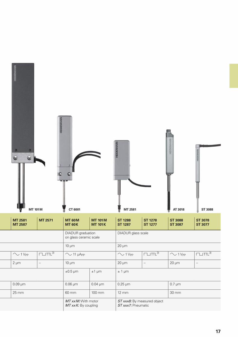
MT 101 M CT 6001 MT 2581 AT 3018 ST 3088
17
MT 2581
MT 2587
MT 2571 MT 60 M
MT 60 K
MT 101 M
MT 101 K
ST 1288
ST 1287
ST 1278
ST 1277
ST 3088
ST 3087
ST 3078
ST 3077
DIADUR graduation on glass ceramic scale
DIADUR glass scale
10 µm 20 µm
1 VPP TTL3) 11 µAPP 1 VPP TTL3) 1 VPP TTL3)
2 µm – 10 µm 20 µm – 20 µm –
±0.5 µm ±1 µm ± 1 µm
0.09 µm 0.06 µm 0.04 µm 0.25 µm 0.7 µm
25 mm 60 mm 100 mm 12 mm 30 mm
MT xx M: With motorMT xx K: By coupling
ST xxx8: By measured objectST xxx7: Pneumatic
18
Angle measurement
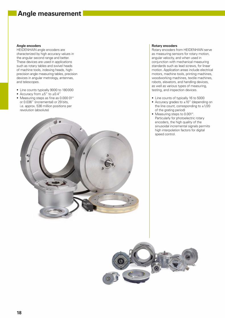
Angle encoders
HEIDENHAIN angle encoders are characterized by high accuracy values in the angular second range and better. These devices are used in applications such as rotary tables and swivel heads of machine tools, indexing heads, high-precision angle measuring tables, precision devices in angular metrology, antennas, and telescopes.
• Line counts typically 9000 to 180 000• Accuracy from ±5” to ±0.4”• Measuring steps as fi ne as 0.000 01°
or 0.036” (incremental) or 29 bits, i.e. approx. 536 million positions per revolution (absolute)
Rotary encoders
Rotary encoders from HEIDENHAIN serve as measuring sensors for rotary motion, angular velocity, and when used in conjunction with mechanical measuring standards such as lead screws, for linear motion. Application areas include electrical motors, machine tools, printing machines, woodworking machines, textile machines, robots, elevators, and handling devices, as well as various types of measuring, testing, and inspection devices.
• Line counts of typically 16 to 5000• Accuracy grades to ±10” (depending on
the line count, corresponding to ±1/20 of the grating period)
• Measuring steps to 0.001°.Particularly for photoelectric rotary encoders, the high quality of the sinusoidal incremental signals permits high interpolation factors for digital speed control.
19
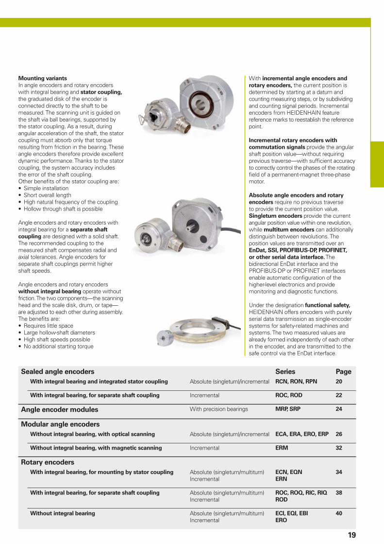
Mounting variants
In angle encoders and rotary encoders with integral bearing and stator coupling, the graduated disk of the encoder is connected directly to the shaft to be measured. The scanning unit is guided on the shaft via ball bearings, supported by the stator coupling. As a result, during angular acceleration of the shaft, the stator coupling must absorb only that torque resulting from friction in the bearing. These angle encoders therefore provide excellent dynamic performance. Thanks to the stator coupling, the system accuracy includes the error of the shaft coupling.Other benefi ts of the stator coupling are:• Simple installation• Short overall length• High natural frequency of the coupling• Hollow through shaft is possible
Angle encoders and rotary encoders with integral bearing for a separate shaft
coupling are designed with a solid shaft. The recommended coupling to the measured shaft compensates radial and axial tolerances. Angle encoders for separate shaft couplings permit higher shaft speeds.
Angle encoders and rotary encoders without integral bearing operate without friction. The two components—the scanning head and the scale disk, drum, or tape—are adjusted to each other during assembly. The benefi ts are:• Requires little space• Large hollow-shaft diameters• High shaft speeds possible• No additional starting torque
With incremental angle encoders and
rotary encoders, the current position is determined by starting at a datum and counting measuring steps, or by subdividing and counting signal periods. Incremental encoders from HEIDENHAIN feature reference marks to reestablish the reference point.
Incremental rotary encoders with
commutation signals provide the angular shaft position value—without requiring previous traverse—with suffi cient accuracy to correctly control the phases of the rotating fi eld of a permanent-magnet three-phase motor.
Absolute angle encoders and rotary
encoders require no previous traverse to provide the current position value. Singleturn encoders provide the current angular position value within one revolution, while multiturn encoders can additionally distinguish between revolutions. The position values are transmitted over an EnDat, SSI, PROFIBUS-DP, PROFINET,
or other serial data interface. The bidirectional EnDat interface and the PROFIBUS-DP or PROFINET interfaces enable automatic confi guration of the higher-level electronics and provide monitoring and diagnostic functions.
Under the designation functional safety, HEIDENHAIN offers encoders with purely serial data transmission as single-encoder systems for safety-related machines and systems. The two measured values are already formed independently of each other in the encoder, and are transmitted to the safe control via the EnDat interface.
Sealed angle encoders Series Page
With integral bearing and integrated stator coupling Absolute (singleturn)/incremental RCN, RON, RPN 20
With integral bearing, for separate shaft coupling Incremental ROC, ROD 22
Angle encoder modules With precision bearings MRP, SRP 24
Modular angle encoders
Without integral bearing, with optical scanning Absolute (singleturn)/incremental ECA, ERA, ERO, ERP 26
Without integral bearing, with magnetic scanning Incremental ERM 32
Rotary encoders
With integral bearing, for mounting by stator coupling Absolute (singleturn/multiturn)Incremental
ECN, EQN
ERN
34
With integral bearing, for separate shaft coupling Absolute (singleturn/multiturn)Incremental
ROC, ROQ, RIC, RIQ
ROD
38
Without integral bearing Absolute (singleturn/multiturn)Incremental
ECI, EQI, EBI
ERO
40
20
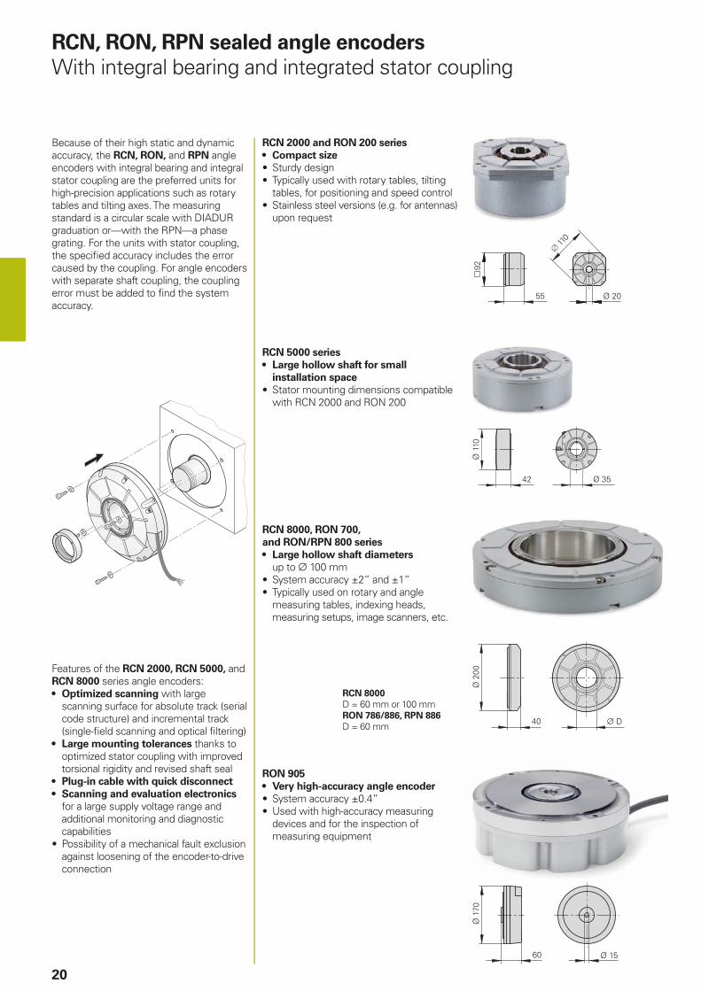
RCN, RON, RPN sealed angle encoders
With integral bearing and integrated stator coupling
Because of their high static and dynamic accuracy, the RCN, RON, and RPN angle encoders with integral bearing and integral stator coupling are the preferred units for high-precision applications such as rotary tables and tilting axes. The measuring standard is a circular scale with DIADUR graduation or—with the RPN—a phase grating. For the units with stator coupling, the specifi ed accuracy includes the error caused by the coupling. For angle encoders with separate shaft coupling, the coupling error must be added to fi nd the system accuracy.
RCN 2000 and RON 200 series
• Compact size
• Sturdy design• Typically used with rotary tables, tilting
tables, for positioning and speed control• Stainless steel versions (e.g. for antennas)
upon request
RCN 8000, RON 700,
and RON/RPN 800 series
• Large hollow shaft diameters up to 100 mm
• System accuracy ±2” and ±1”• Typically used on rotary and angle
measuring tables, indexing heads, measuring setups, image scanners, etc.
RON 905
• Very high-accuracy angle encoder
• System accuracy ±0.4”• Used with high-accuracy measuring
devices and for the inspection of measuring equipment
RCN 8000
D = 60 mm or 100 mmRON 786/886, RPN 886
D = 60 mm
RCN 5000 series
• Large hollow shaft for small
installation space
• Stator mounting dimensions compatible with RCN 2000 and RON 200
Features of the RCN 2000, RCN 5000, and RCN 8000 series angle encoders:• Optimized scanning with large
scanning surface for absolute track (serial code structure) and incremental track (single-fi eld scanning and optical fi ltering)
• Large mounting tolerances thanks to optimized stator coupling with improved torsional rigidity and revised shaft seal
• Plug-in cable with quick disconnect
• Scanning and evaluation electronics for a large supply voltage range and additional monitoring and diagnostic capabilities
• Possibility of a mechanical fault exclusion against loosening of the encoder-to-drive connection

21
Absolute Incremental
RCN 2380
RCN 2580
RCN 23101)
RCN 25101)
RCN 2390 F
RCN 2590 F
RCN 2390 M
RCN 2590 M
RON 225
RON 275
RON 285
RON 287
Interface EnDat 2.22) with 1 VPP
EnDat 2.22) Fanuc i Mitsubishi TTL 1 VPP
Position values/revolution RCN 23x0: 67 108 864 (26 bits); RCN 25x0: 268 435 456 (28 bits) –
Signal periods/revolution 16 384 – 18 0003) 90 000/180 0004)
18 000
System accuracy RCN 23x0: ±5”; RCN 25x0: ±2.5” ±5” ±5”; ±2.5”
Mech. permissible speed 1500 rpm 3000 rpm
Absolute
RCN 5380
RCN 5580
RCN 53101)
RCN 55101)
RCN 5390 F
RCN 5590 F
RCN 5390 M
RCN 5590 M
Interface EnDat 2.22) with 1 VPP
EnDat 2.22) Fanuc i Mitsubishi
Position values/revolution RCN 53x0: 67 108 864 (26 bits); RCN 55x0: 268 435 456 (28 bits)
Signal periods/revolution 16 384 –
System accuracy RCN 53x0: ±5”; RCN 55x0: ±2.5”
Mech. permissible speed 1500 rpm
Incremental
RON 905
Interface 11µAPP
Signal periods/revolution 36 000
System accuracy ±0.4”
Mech. permissible speed 100 rpm
1) Also available with functional safety2) DRIVE-CLiQ via EIB; PROFIBUS-DP via gateway3) 2-fold integrated interpolation4) 5/10-fold integrated interpolation
DRIVE-CLiQ is a registered trademark of SIEMENS AG.
Absolute Incremental
RCN 8380
RCN 8580
RCN 83101)
RCN 85101)
RCN 8390 F
RCN 8590 F
RCN 8390 M
RCN 8590 M
RON 786 RON 886 RPN 886
Interface EnDat 2.22) with 1 VPP
EnDat 2.22) Fanuc i Mitsubishi 1 VPP
Position values/revolution 536 870 912 (29 bits) –
Signal periods/revolution 32 768 – – 18 000, 36 000
36 000 180 000
System accuracy RCN 83x0: ±2”; RCN 85x0: ±1” ±2” ±1”
Mech. permissible speed 500 rpm 1000 rpm
ROD 780, ROD 880
ROC 7000
22
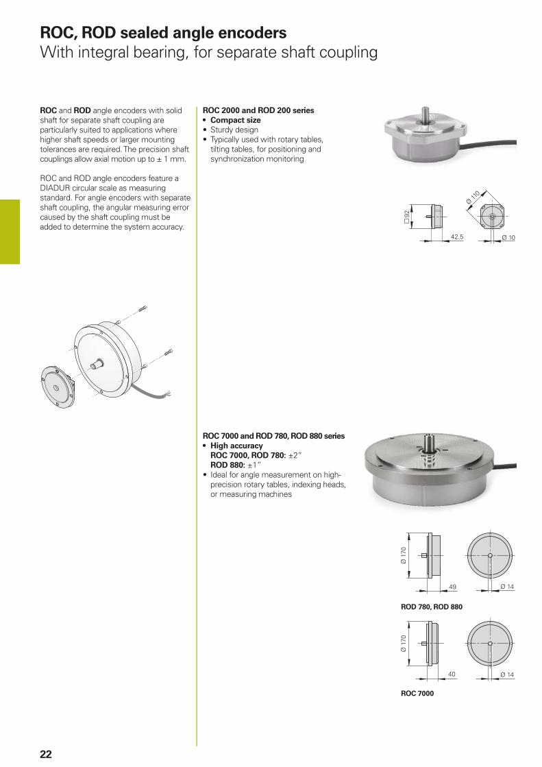
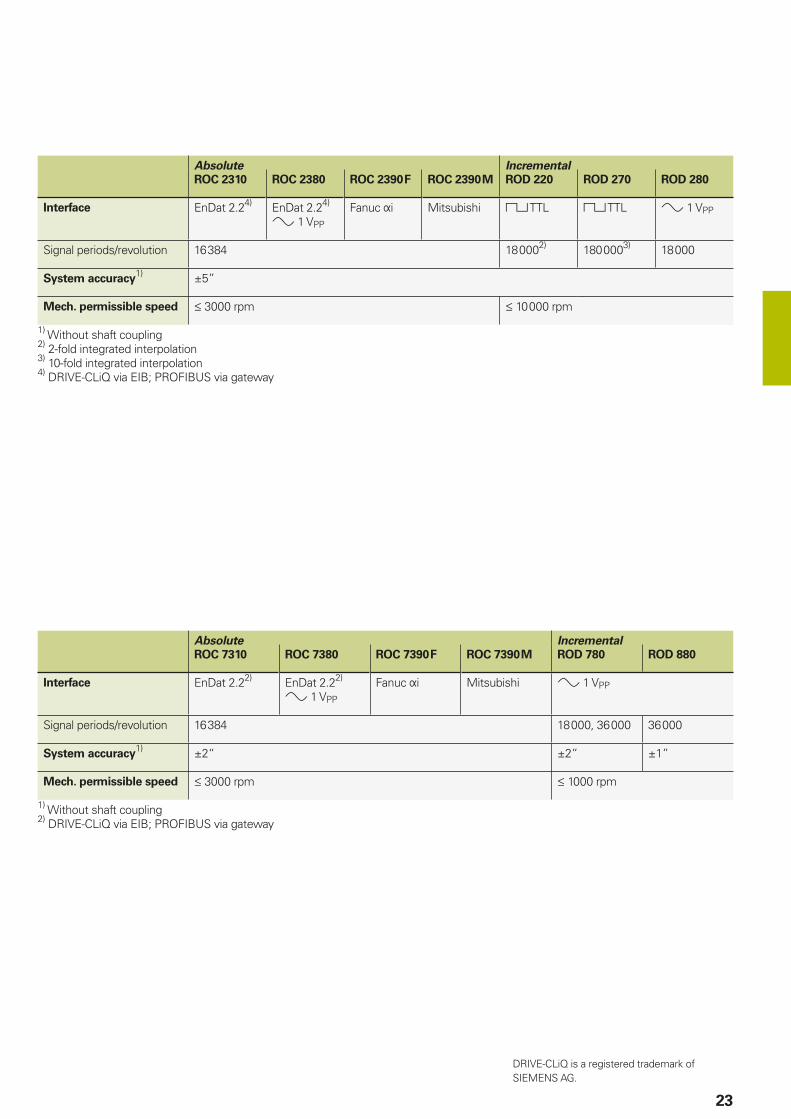
ROC, ROD sealed angle encoders
With integral bearing, for separate shaft coupling
ROC and ROD angle encoders with solid shaft for separate shaft coupling are particularly suited to applications where higher shaft speeds or larger mounting tolerances are required. The precision shaft couplings allow axial motion up to ± 1 mm.
ROC and ROD angle encoders feature a DIADUR circular scale as measuring standard. For angle encoders with separate shaft coupling, the angular measuring error caused by the shaft coupling must be added to determine the system accuracy.
ROC 2000 and ROD 200 series
• Compact size
• Sturdy design• Typically used with rotary tables,
tilting tables, for positioning and synchronization monitoring
ROC 7000 and ROD 780, ROD 880 series
• High accuracy
ROC 7000, ROD 780: ±2”ROD 880: ±1”
• Ideal for angle measurement on high-precision rotary tables, indexing heads, or measuring machines
23
Absolute Incremental
ROC 2310 ROC 2380 ROC 2390 F ROC 2390 M ROD 220 ROD 270 ROD 280
Interface EnDat 2.24) EnDat 2.24)
1 VPP
Fanuc i Mitsubishi TTL TTL 1 VPP
Signal periods/revolution 16 384 18 0002) 180 0003) 18 000
System accuracy1) ±5”
Mech. permissible speed 3000 rpm 10 000 rpm
1) Without shaft coupling2) 2-fold integrated interpolation3) 10-fold integrated interpolation4) DRIVE-CLiQ via EIB; PROFIBUS via gateway
Absolute Incremental
ROC 7310 ROC 7380 ROC 7390 F ROC 7390 M ROD 780 ROD 880
Interface EnDat 2.22) EnDat 2.22)
1 VPP
Fanuc i Mitsubishi 1 VPP
Signal periods/revolution 16 384 18 000, 36 000 36 000
System accuracy1) ±2“ ±2” ±1”
Mech. permissible speed 3000 rpm 1000 rpm
1) Without shaft coupling2) DRIVE-CLiQ via EIB; PROFIBUS via gateway
DRIVE-CLiQ is a registered trademark of SIEMENS AG.

MRP 2010
MRP 5010
MRP 8010
SRP 5000
24
MRP 8000 series
Angle encoder modules with integrated encoder and bearing• Compact dimensions• High measuring and bearing accuracy• Hollow shaft 100 mm
MRP 5000 series
Angle encoder modules with integrated encoder and bearing• Compact dimensions• High measuring and bearing accuracy• Hollow shaft 35 mm
MRP 2000 series
Angle encoder modules with integrated encoder and bearing• Very small dimensions• High measuring and bearing accuracy• Hollow shaft 10 mm
SRP 5000 series
Angle encoder modules with integrated encoder, bearing, and torque motor• Compact dimensions• Torque motor with low detent torque• Peak torque: 2.70 Nm• Rated torque: 0.385 Nm
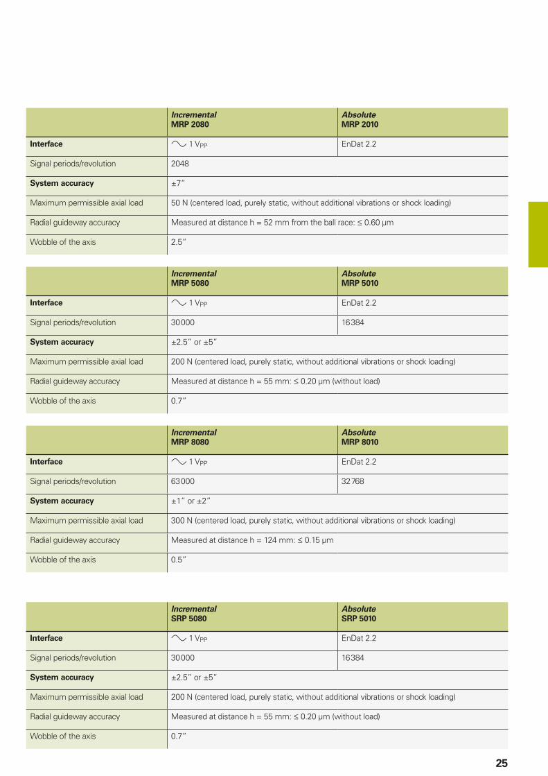
MRP, SRP angle encoder modules
Assemblies for high-precision rotary axes
MRP angle encoder module
A combination of angle encoder
and bearing
Angle encoder modules from HEIDENHAIN are combinations of angle encoders and high-precision bearings that are optimally adjusted to each other. They are characterized by their high degree of measuring and bearing accuracy, their very high resolution, and the highest degree of repeatability. The low starting torque permits smooth motions. Due to their design as completely specifi ed and tested composite components, handling and installation is very simple.
SRP angle encoder module
A combination of angle encoder,
bearing, and motor
SRP angle encoder modules are additionally equipped with an integrated torque motor. They combine a motor, precision bearing, and encoder with very high accuracy in one compact system. The torque motor with its very low detent torque enables extraordinarily smooth motion control. Neither disruptive detent torques nor radial forces impair the high guideway accuracy of the bearing.
Mounting option 1
Mounting option 2
25
Incremental Absolute
SRP 5080 SRP 5010
Interface 1 VPP EnDat 2.2
Signal periods/revolution 30 000 16 384
System accuracy ±2.5” or ±5”
Maximum permissible axial load 200 N (centered load, purely static, without additional vibrations or shock loading)
Radial guideway accuracy Measured at distance h = 55 mm: 0.20 µm (without load)
Wobble of the axis 0.7”
Incremental Absolute
MRP 8080 MRP 8010
Interface 1 VPP EnDat 2.2
Signal periods/revolution 63 000 32 768
System accuracy ±1” or ±2”
Maximum permissible axial load 300 N (centered load, purely static, without additional vibrations or shock loading)
Radial guideway accuracy Measured at distance h = 124 mm: 0.15 µm
Wobble of the axis 0.5”
Incremental Absolute
MRP 5080 MRP 5010
Interface 1 VPP EnDat 2.2
Signal periods/revolution 30 000 16 384
System accuracy ±2.5” or ±5”
Maximum permissible axial load 200 N (centered load, purely static, without additional vibrations or shock loading)
Radial guideway accuracy Measured at distance h = 55 mm: 0.20 µm (without load)
Wobble of the axis 0.7”
Incremental Absolute
MRP 2080 MRP 2010
Interface 1 VPP EnDat 2.2
Signal periods/revolution 2048
System accuracy ±7”
Maximum permissible axial load 50 N (centered load, purely static, without additional vibrations or shock loading)
Radial guideway accuracy Measured at distance h = 52 mm from the ball race: 0.60 µm
Wobble of the axis 2.5”

ERO 6000
26
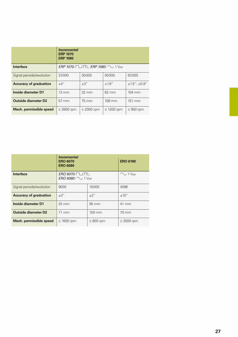
ERP, ERO modular angle encoders
Without integral bearing, with optical scanning
ERP 1000 series
• Very high resolution and accuracy
• Small mass, low mass moment of inertia• Very fl at design• Circular scale available as full circle or
segment
ERO 6000 series
• Very fl at design • High system accuracy• Simple installation
ERO 6100 series
• For dynamic applications with reduced accuracy requirements
• Application examples include printing machines and handling axes
• Large inside diameter
The HEIDENHAIN ERP and ERO angle encoders without integral bearing operate without friction and use a circular glass scale with hub as the graduation carrier. They are characterized by their low weight and compact dimensions. They thus permit high accuracies and are designed for integration in machine elements or components.
The attainable system accuracy depends on the eccentricity of the graduation to the drive shaft bearing, as well as the radial runout and wobble of the bearing.
A circular scale with phase grating serves as the basis for the high accuracy of the ERP encoders. This makes them particularly attractive for high-precision angle measuring tables and precision devices in angular metrology.
Applications for the ERO are found in metrology, in compact rotary tables, and in precise, highly dynamic drives.
27
Incremental
ERP 1070
ERP 1080
Interface ERP 1070: TTL; ERP 1080: 1 VPP
Signal periods/revolution 23 000 30 000 50 000 63 000
Accuracy of graduation ±4“ ±3” ±1.8” ±1.5”; ±0.9”
Inside diameter D1 13 mm 32 mm 62 mm 104 mm
Outside diameter D2 57 mm 75 mm 109 mm 151 mm
Mech. permissible speed 2600 rpm 2000 rpm 1200 rpm 950 rpm
Incremental
ERO 6070
ERO 6080
ERO 6180
Interface ERO 6070: TTL; ERO 6080: 1 VPP
1 VPP
Signal periods/revolution 9000 18 000 4096
Accuracy of graduation ±3” ±2” ±10”
Inside diameter D1 25 mm 95 mm 41 mm
Outside diameter D2 71 mm 150 mm 70 mm
Mech. permissible speed 1600 rpm 800 rpm 3500 rpm
28
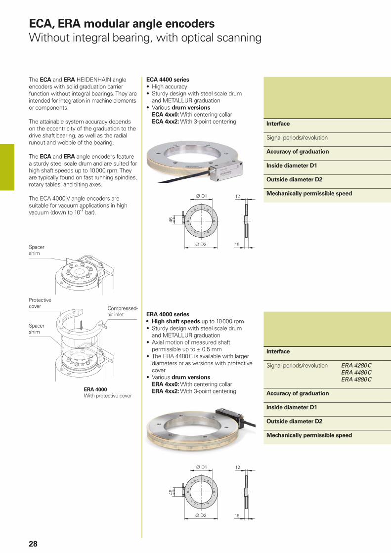
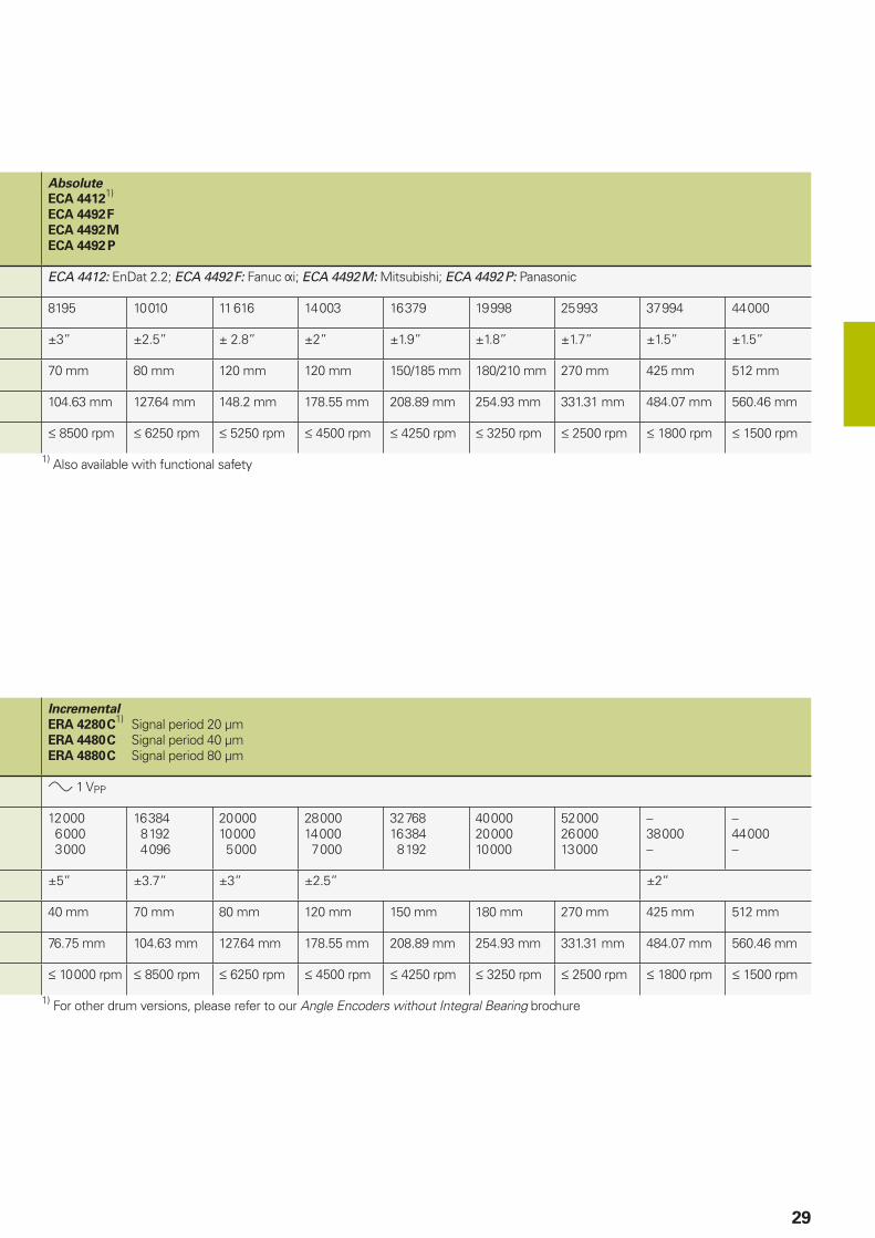
ECA, ERA modular angle encoders
Without integral bearing, with optical scanning
The ECA and ERA HEIDENHAIN angle encoders with solid graduation carrier function without integral bearings. They are intended for integration in machine elements or components.
The attainable system accuracy depends on the eccentricity of the graduation to the drive shaft bearing, as well as the radial runout and wobble of the bearing.
The ECA and ERA angle encoders feature a sturdy steel scale drum and are suited for high shaft speeds up to 10 000 rpm. They are typically found on fast running spindles, rotary tables, and tilting axes.
The ECA 4000 V angle encoders are suitable for vacuum applications in high vacuum (down to 10-7 bar).
ERA 4000 series
• High shaft speeds up to 10 000 rpm• Sturdy design with steel scale drum
and METALLUR graduation• Axial motion of measured shaft
permissible up to ± 0.5 mm• The ERA 4480 C is available with larger
diameters or as versions with protective cover
• Various drum versions ERA 4xx0: With centering collarERA 4xx2: With 3-point centering
Interface
Signal periods/revolution ERA 4280 C ERA 4480 C ERA 4880 C
Accuracy of graduation
Inside diameter D1
Outside diameter D2
Mechanically permissible speed
ECA 4400 series
• High accuracy• Sturdy design with steel scale drum
and METALLUR graduation• Various drum versions
ECA 4xx0: With centering collarECA 4xx2: With 3-point centering Interface
Signal periods/revolution
Accuracy of graduation
Inside diameter D1
Outside diameter D2
Mechanically permissible speed
Spacer shim
Protective cover Compressed-
air inlet
Spacer shim
ERA 4000
With protective cover
29
Incremental
ERA 4280 C1)
Signal period 20 µmERA 4480 C Signal period 40 µmERA 4880 C Signal period 80 µm
1 VPP
12 000 6 000 3 000
16 384 8 192 4 096
20 00010 000 5 000
28 00014 000 7 000
32 76816 384 8 192
40 00020 00010 000
52 00026 00013 000
–38 000–
–44 000–
±5” ±3.7” ±3” ±2.5” ±2”
40 mm 70 mm 80 mm 120 mm 150 mm 180 mm 270 mm 425 mm 512 mm
76.75 mm 104.63 mm 127.64 mm 178.55 mm 208.89 mm 254.93 mm 331.31 mm 484.07 mm 560.46 mm
10 000 rpm 8500 rpm 6250 rpm 4500 rpm 4250 rpm 3250 rpm 2500 rpm 1800 rpm 1500 rpm
1) For other drum versions, please refer to our Angle Encoders without Integral Bearing brochure
Absolute
ECA 44121)
ECA 4492 F
ECA 4492 M
ECA 4492 P
ECA 4412: EnDat 2.2; ECA 4492 F: Fanuc i; ECA 4492 M: Mitsubishi; ECA 4492 P: Panasonic
8195 10 010 11 616 14 003 16 379 19 998 25 993 37 994 44 000
±3” ±2.5” ± 2.8” ±2” ±1.9” ±1.8” ±1.7” ±1.5” ±1.5”
70 mm 80 mm 120 mm 120 mm 150/185 mm 180/210 mm 270 mm 425 mm 512 mm
104.63 mm 127.64 mm 148.2 mm 178.55 mm 208.89 mm 254.93 mm 331.31 mm 484.07 mm 560.46 mm
8500 rpm 6250 rpm 5250 rpm 4500 rpm 4250 rpm 3250 rpm 2500 rpm 1800 rpm 1500 rpm
1) Also available with functional safety
ERA 8480 C
ERA 7481 C
ERA 7400 C
ERA 8400 C
ERA 7481 C
ERA 8480 C
30
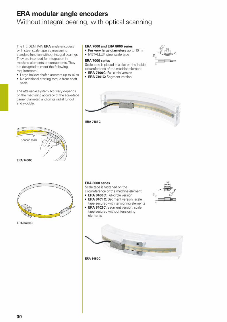
ERA modular angle encoders
Without integral bearing, with optical scanning
The HEIDENHAIN ERA angle encoders with steel scale tape as measuring standard function without integral bearings. They are intended for integration in machine elements or components. They are designed to meet the following requirements:• Large hollow shaft diameters up to 10 m• No additional starting torque from shaft
seals
The attainable system accuracy depends on the machining accuracy of the scale-tape carrier diameter, and on its radial runout and wobble.
ERA 7000 and ERA 8000 series
• For very large diameters up to 10 m• METALLUR steel scale tape
ERA 7000 series
Scale tape is placed in a slot on the inside circumference of the machine element• ERA 7400 C: Full-circle version• ERA 7401C: Segment version
Spacer shim
ERA 8000 series
Scale tape is fastened on the circumference of the machine element• ERA 8400 C: Full-circle version• ERA 8401 C: Segment version, scale
tape secured with tensioning elements• ERA 8402 C: Segment version, scale
tape secured without tensioning elements
31
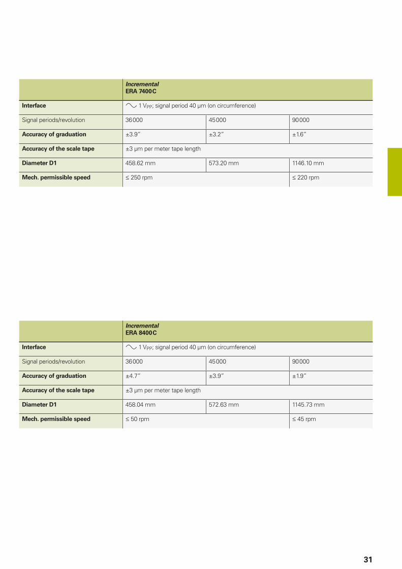
Incremental
ERA 7400 C
Interface 1 VPP; signal period 40 µm (on circumference)
Signal periods/revolution 36 000 45 000 90 000
Accuracy of graduation ±3.9” ±3.2” ±1.6”
Accuracy of the scale tape ±3 µm per meter tape length
Diameter D1 458.62 mm 573.20 mm 1146.10 mm
Mech. permissible speed 250 rpm 220 rpm
Incremental
ERA 8400 C
Interface 1 VPP; signal period 40 µm (on circumference)
Signal periods/revolution 36 000 45 000 90 000
Accuracy of graduation ±4.7” ±3.9” ±1.9”
Accuracy of the scale tape ±3 µm per meter tape length
Diameter D1 458.04 mm 572.63 mm 1145.73 mm
Mech. permissible speed 50 rpm 45 rpm
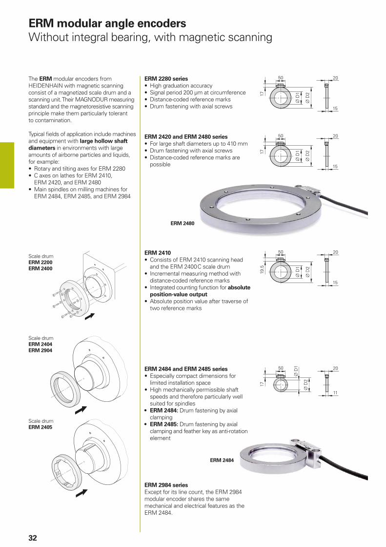
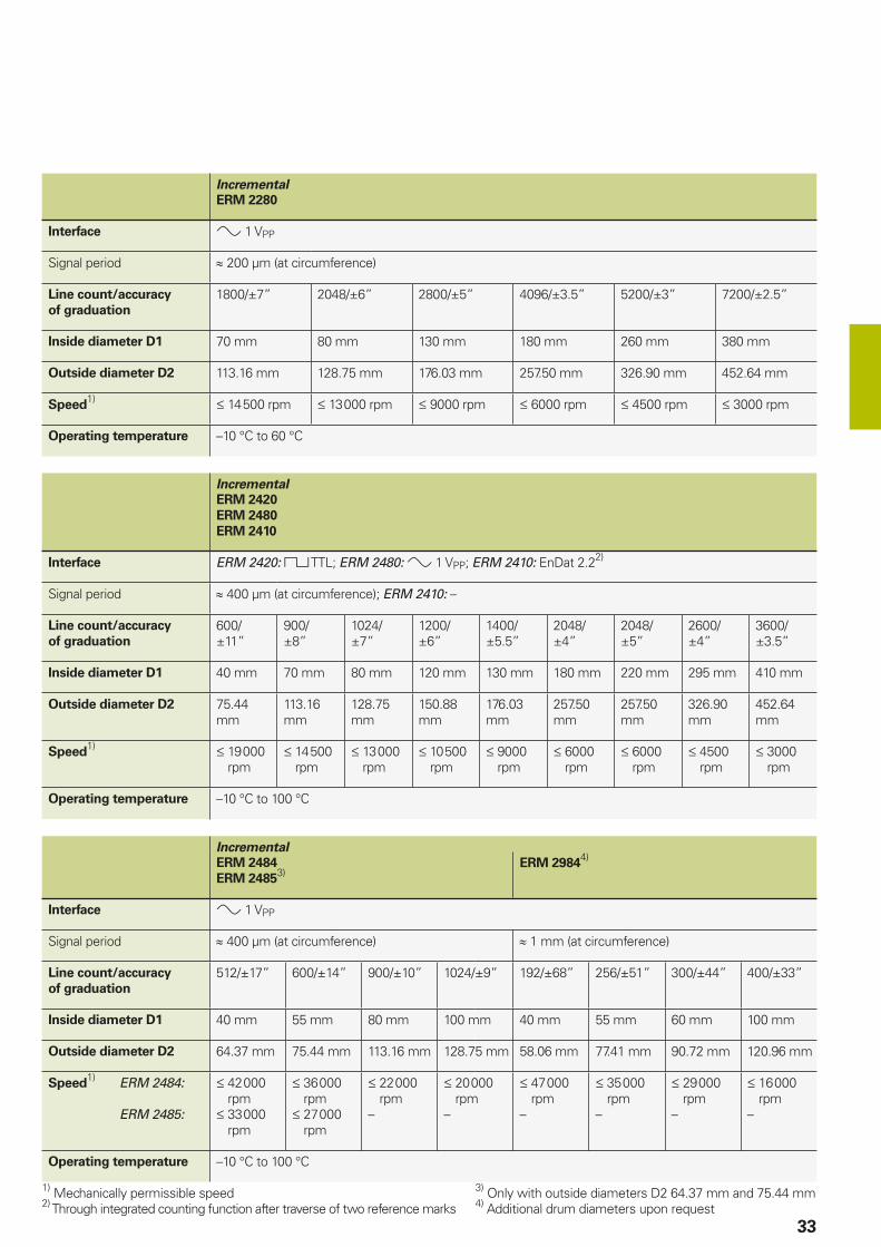
ERM 2484
ERM 2480
4
32
The ERM modular encoders from HEIDENHAIN with magnetic scanning consist of a magnetized scale drum and a scanning unit. Their MAGNODUR measuring standard and the magnetoresistive scanning principle make them particularly tolerant to contamination.
Typical fi elds of application include machines and equipment with large hollow shaft
diameters in environments with large amounts of airborne particles and liquids, for example: • Rotary and tilting axes for ERM 2280• C axes on lathes for ERM 2410,
ERM 2420, and ERM 2480• Main spindles on milling machines for
ERM 2484, ERM 2485, and ERM 2984
ERM modular angle encoders
Without integral bearing, with magnetic scanning
Scale drumERM 2404
ERM 2904
Scale drumERM 2405
ERM 2420 and ERM 2480 series
• For large shaft diameters up to 410 mm • Drum fastening with axial screws• Distance-coded reference marks are
possible
ERM 2484 and ERM 2485 series
• Especially compact dimensions for limited installation space
• High mechanically permissible shaft speeds and therefore particularly well suited for spindles
• ERM 2484: Drum fastening by axial clamping
• ERM 2485: Drum fastening by axial clamping and feather key as anti-rotation element
Scale drumERM 2200
ERM 2400
ERM 2410
• Consists of ERM 2410 scanning head and the ERM 2400 C scale drum
• Incremental measuring method with distance-coded reference marks
• Integrated counting function for absolute
position-value output
• Absolute position value after traverse of two reference marks
ERM 2984 series
Except for its line count, the ERM 2984 modular encoder shares the same mechanical and electrical features as the ERM 2484.
ERM 2280 series
• High graduation accuracy• Signal period 200 µm at circumference• Distance-coded reference marks• Drum fastening with axial screws
33
Incremental
ERM 2280
Interface 1 VPP
Signal period 200 µm (at circumference)
Line count/accuracy
of graduation
1800/±7” 2048/±6” 2800/±5” 4096/±3.5” 5200/±3” 7200/±2.5”
Inside diameter D1 70 mm 80 mm 130 mm 180 mm 260 mm 380 mm
Outside diameter D2 113.16 mm 128.75 mm 176.03 mm 257.50 mm 326.90 mm 452.64 mm
Speed1) 14 500 rpm 13 000 rpm 9000 rpm 6000 rpm 4500 rpm 3000 rpm
Operating temperature –10 °C to 60 °C
Incremental
ERM 2484
ERM 24853)
ERM 29844)
Interface 1 VPP
Signal period 400 µm (at circumference) 1 mm (at circumference)
Line count/accuracy
of graduation
512/±17” 600/±14” 900/±10” 1024/±9” 192/±68” 256/±51” 300/±44” 400/±33”
Inside diameter D1 40 mm 55 mm 80 mm 100 mm 40 mm 55 mm 60 mm 100 mm
Outside diameter D2 64.37 mm 75.44 mm 113.16 mm 128.75 mm 58.06 mm 77.41 mm 90.72 mm 120.96 mm
Speed1) ERM 2484:
ERM 2485:
42 000 rpm
33 000 rpm
36 000 rpm
27 000 rpm
000 rpm
–
20 000 rpm
–
000 rpm
–
35 000 rpm
–
000 rpm
–
000 rpm
–
Operating temperature –10 °C to 100 °C
1) Mechanically permissible speed2) Through integrated counting function after traverse of two reference marks
3) Only with outside diameters D2 64.37 mm and 75.44 mm4) Additional drum diameters upon request
Incremental
ERM 2420
ERM 2480
ERM 2410
Interface ERM 2420: TTL; ERM 2480: 1 VPP; ERM 2410: EnDat 2.22)
Signal period 400 µm (at circumference); ERM 2410: –
Line count/accuracy
of graduation
600/±11”
900/±8”
1024/±7”
1200/±6”
1400/±5.5”
2048/±4”
2048/±5”
2600/±4”
3600/±3.5”
Inside diameter D1 40 mm 70 mm 80 mm 120 mm 130 mm 180 mm 220 mm 295 mm 410 mm
Outside diameter D2 75.44 mm
113.16 mm
128.75 mm
150.88 mm
176.03 mm
257.50 mm
257.50 mm
326.90 mm
452.64 mm
Speed1) 19 000
rpm14 500
rpm13 000
rpm10 500
rpm9000
rpm6000
rpm6000
rpm4500
rpm3000
rpm
Operating temperature –10 °C to 100 °C
ECN/EQN/ERN 1000
ECN/EQN/ERN 400
ECN/ERN 100
34
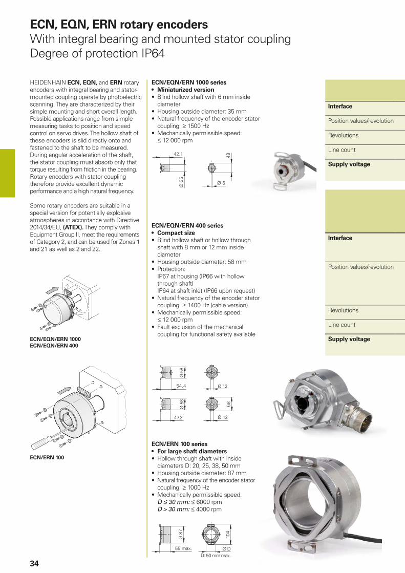
ECN, EQN, ERN rotary encoders
With integral bearing and mounted stator couplingDegree of protection IP64
HEIDENHAIN ECN, EQN, and ERN rotary encoders with integral bearing and stator-mounted coupling operate by photoelectric scanning. They are characterized by their simple mounting and short overall length. Possible applications range from simple measuring tasks to position and speed control on servo drives. The hollow shaft of these encoders is slid directly onto and fastened to the shaft to be measured. During angular acceleration of the shaft, the stator coupling must absorb only that torque resulting from friction in the bearing. Rotary encoders with stator coupling therefore provide excellent dynamic performance and a high natural frequency.
Some rotary encoders are suitable in a special version for potentially explosive atmospheres in accordance with Directive 2014/34/EU, (ATEX). They comply with Equipment Group II, meet the requirements of Category 2, and can be used for Zones 1 and 21 as well as 2 and 22.
ECN/EQN/ERN 1000 series
• Miniaturized version
• Blind hollow shaft with 6 mm inside diameter
• Housing outside diameter: 35 mm• Natural frequency of the encoder stator
coupling: 1500 Hz• Mechanically permissible speed: 12 000 rpm
ECN/EQN/ERN 400 series
• Compact size
• Blind hollow shaft or hollow through shaft with 8 mm or 12 mm inside diameter
• Housing outside diameter: 58 mm• Protection:
IP67 at housing (IP66 with hollow through shaft)IP64 at shaft inlet (IP66 upon request)
• Natural frequency of the encoder stator coupling: 1400 Hz (cable version)
• Mechanically permissible speed: 12 000 rpm
• Fault exclusion of the mechanical coupling for functional safety available
ECN/ERN 100 series
• For large shaft diameters
• Hollow through shaft with inside diameters D: 20, 25, 38, 50 mm
• Housing outside diameter: 87 mm• Natural frequency of the encoder stator
coupling: 1000 Hz• Mechanically permissible speed:
D 30 mm: 6000 rpm D > 30 mm: 4000 rpm
Interface
Position values/revolution
Revolutions
Line count
Supply voltage
Interface
Position values/revolution
Revolutions
Line count
Supply voltage
PROFIBUS-DP/PROFINET
35
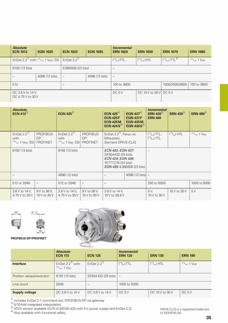
Absolute Incremental
ECN 113 ECN 125 ERN 120 ERN 130 ERN 180
Interface EnDat 2.21) with 1 VPP
EnDat 2.21) TTL HTL 1 VPP
Position values/revolution 8192 (13 bits) 33 554 432 (25 bits) –
Line count 2048 – 1000 to 5000
Supply voltage DC 3.6 V to 14 V DC 3.6 V to 14 V DC 5 V DC 10 V to 30 V DC 5 V
1) Includes EnDat 2.1 command set; PROFIBUS-DP via gateway2) 5/10-fold integrated interpolation3) ATEX version available (ECN 413/EQN 425 with 5 V power supply and EnDat 2.2)4) Also available with functional safety
Absolute Incremental
ECN 1013 EQN 1025 ECN 1023 EQN 1035 ERN 1020 ERN 1030 ERN 1070 ERN 1080
EnDat 2.21) with 1 VPP; SSI EnDat 2.21) TTL HTL TTL2) 1 VPP
8192 (13 bits) 8 388 608 (23 bits) –
– 4096 (12 bits) – 4096 (12 bits) –
512 – 100 to 3600 1000/2500/3600 100 to 3600
DC 3.6 V to 14 V;DC 4.75 V to 30 V
DC 5 V DC 10 V to 30 V DC 5 V
Absolute Incremental
ECN 4133)
EQN 4253)
ECN 4254)
ECN 425 F
ECN 425 M
ECN 424 S4)
EQN 4374)
EQN 437 F
EQN 435 M
EQN 436 S4)
ERN 4203)
ERN 460
ERN 4303)
ERN 4803)
EnDat 2.21) with 1 VPP; SSI
PROFIBUS-DP; PROFINET
EnDat 2.21) with 1 VPP; SSI
PROFIBUS-DP; PROFINET
EnDat 2.21); Fanuc i;Mitsubishi;Siemens DRIVE-CLiQ
TTL;TTL
HTL 1 VPP
8192 (13 bits) 8192 (13 bits) ECN 425, EQN 437: 33 554 432 (25 bits)ECN 424, EQN 436: 16 777 216 (24 bits)EQN 435: 8 388 608 (23 bits)
–
– 4096 (12 bits) – 4096 (12 bits) –
512 or 2048 – 512 or 2048 – – 250 to 5000 1000 to 5000
3.6 V to 14 V;4.75 V to 30 V
9 V to 36 V;10 V to 30 V
3.6 V to 14 V;4.75 V to 30 V
9 V to 36 V;10 V to 30 V
3.6 V to 14 V;10 V to 28.8 V
5 V;10 V to 30 V
10 V to 30 V 5 V
DRIVE-CLiQ is a registered trademark of SIEMENS AG.
ECN/EQN 1100
ERN 1123
ECN/EQN/ERN 1300
36
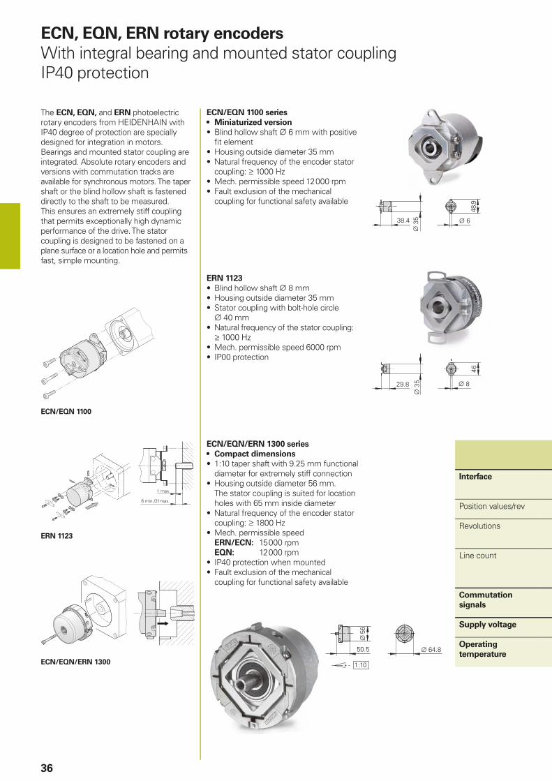
ECN, EQN, ERN rotary encoders
With integral bearing and mounted stator couplingIP40 protection
The ECN, EQN, and ERN photoelectric rotary encoders from HEIDENHAIN with IP40 degree of protection are specially designed for integration in motors. Bearings and mounted stator coupling are integrated. Absolute rotary encoders and versions with commutation tracks are available for synchronous motors. The taper shaft or the blind hollow shaft is fastened directly to the shaft to be measured. This ensures an extremely stiff coupling that permits exceptionally high dynamic performance of the drive. The stator coupling is designed to be fastened on a plane surface or a location hole and permits fast, simple mounting.
ECN/EQN 1100 series
• Miniaturized version
• Blind hollow shaft 6 mm with positive fi t element
• Housing outside diameter 35 mm• Natural frequency of the encoder stator
coupling: 1000 Hz• Mech. permissible speed 12 000 rpm• Fault exclusion of the mechanical
coupling for functional safety available
ECN/EQN/ERN 1300 series
• Compact dimensions
• 1:10 taper shaft with 9.25 mm functional diameter for extremely stiff connection
• Housing outside diameter 56 mm.The stator coupling is suited for location holes with 65 mm inside diameter
• Natural frequency of the encoder stator coupling: 1800 Hz
• Mech. permissible speedERN/ECN: 15 000 rpmEQN: 12 000 rpm
• IP40 protection when mounted• Fault exclusion of the mechanical
coupling for functional safety available
Interface
Position values/rev
Revolutions
Line count
Commutation
signals
Supply voltage
Operating
temperature
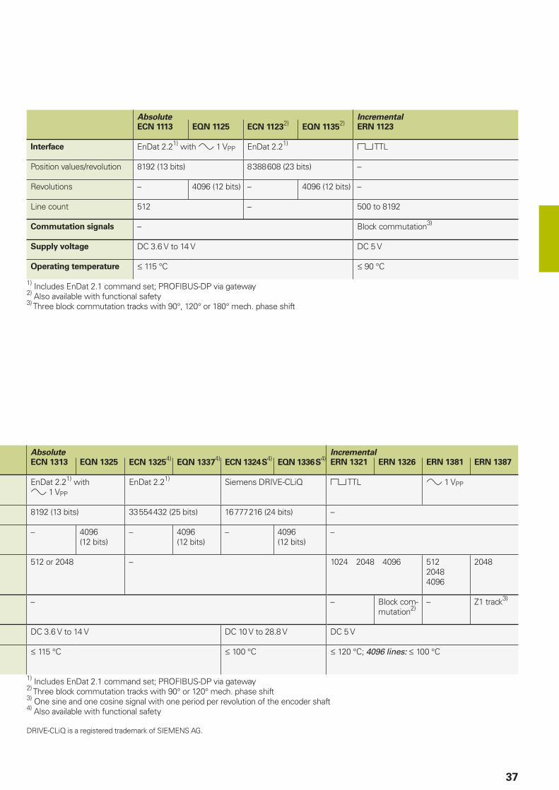
ERN 1123
• Blind hollow shaft 8 mm• Housing outside diameter 35 mm• Stator coupling with bolt-hole circle 40 mm
• Natural frequency of the stator coupling: 1000 Hz
• Mech. permissible speed 6000 rpm• IP00 protection
37
Absolute Incremental
ECN 1113 EQN 1125 ECN 11232)
EQN 11352)
ERN 1123
Interface EnDat 2.21) with 1 VPP EnDat 2.21) TTL
Position values/revolution 8192 (13 bits) 8 388 608 (23 bits) –
Revolutions – 4096 (12 bits) – 4096 (12 bits) –
Line count 512 – 500 to 8192
Commutation signals – Block commutation3)
Supply voltage DC 3.6 V to 14 V DC 5 V
Operating temperature 115 °C 90 °C
1) Includes EnDat 2.1 command set; PROFIBUS-DP via gateway2) Also available with functional safety3) Three block commutation tracks with 90°, 120° or 180° mech. phase shift
Absolute Incremental
ECN 1313 EQN 1325 ECN 13254)
EQN 13374)
ECN 1324 S4)
EQN 1336 S4)
ERN 1321 ERN 1326 ERN 1381 ERN 1387
EnDat 2.21) with 1 VPP
EnDat 2.21) Siemens DRIVE-CLiQ TTL 1 VPP
8192 (13 bits) 33 554 432 (25 bits) 16 777 216 (24 bits) –
– 4096 (12 bits)
– 4096 (12 bits)
– 4096 (12 bits)
–
512 or 2048 – 1024 2048 4096 51220484096
2048
– – Block com-mutation2)
– Z1 track3)
DC 3.6 V to 14 V DC 10 V to 28.8 V DC 5 V
115 °C 100 °C 120 °C; 4096 lines: 100 °C
1) Includes EnDat 2.1 command set; PROFIBUS-DP via gateway2) Three block commutation tracks with 90° or 120° mech. phase shift3) One sine and one cosine signal with one period per revolution of the encoder shaft4) Also available with functional safety
DRIVE-CLiQ is a registered trademark of SIEMENS AG.
HR 1120
38
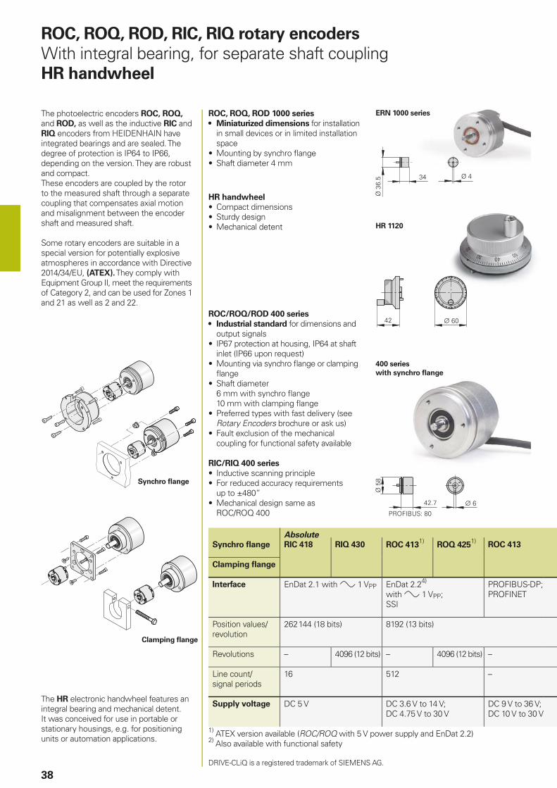
ROC, ROQ, ROD, RIC, RIQ rotary encoders
With integral bearing, for separate shaft couplingHR handwheel
The photoelectric encoders ROC, ROQ, and ROD, as well as the inductive RIC and RIQ encoders from HEIDENHAIN have integrated bearings and are sealed. The degree of protection is IP64 to IP66, depending on the version. They are robust and compact.These encoders are coupled by the rotor to the measured shaft through a separate coupling that compensates axial motion and misalignment between the encoder shaft and measured shaft.
Some rotary encoders are suitable in a special version for potentially explosive atmospheres in accordance with Directive 2014/34/EU, (ATEX). They comply with Equipment Group II, meet the requirements of Category 2, and can be used for Zones 1 and 21 as well as 2 and 22.
ROC, ROQ, ROD 1000 series
• Miniaturized dimensions for installation in small devices or in limited installation space
• Mounting by synchro fl ange• Shaft diameter 4 mm
Clamping fl ange
Synchro fl ange
ROC/ROQ/ROD 400 series
• Industrial standard for dimensions and output signals
• IP67 protection at housing, IP64 at shaft inlet (IP66 upon request)
• Mounting via synchro fl ange or clamping fl ange
• Shaft diameter6 mm with synchro fl ange10 mm with clamping fl ange
• Preferred types with fast delivery (see Rotary Encoders brochure or ask us)
• Fault exclusion of the mechanical coupling for functional safety available
RIC/RIQ 400 series
• Inductive scanning principle• For reduced accuracy requirements
up to ±480”• Mechanical design same as
ROC/ROQ 400
400 series
with synchro fl ange
ERN 1000 series
Absolute
Synchro fl ange RIC 418 RIQ 430 ROC 4131)
ROQ 4251)
ROC 413
Clamping fl ange
Interface EnDat 2.1 with 1 VPP EnDat 2.24) with 1 VPP; SSI
PROFIBUS-DP; PROFINET
Position values/revolution
262 144 (18 bits) 8192 (13 bits)
Revolutions – 4096 (12 bits) – 4096 (12 bits) –
Line count/signal periods
16 512 –
Supply voltage DC 5 V DC 3.6 V to 14 V;DC 4.75 V to 30 V
DC 9 V to 36 V;DC 10 V to 30 V
1) ATEX version available (ROC/ROQ with 5 V power supply and EnDat 2.2)2) Also available with functional safety
DRIVE-CLiQ is a registered trademark of SIEMENS AG.
The HR electronic handwheel features an integral bearing and mechanical detent. It was conceived for use in portable or stationary housings, e.g. for positioning units or automation applications.
HR handwheel
• Compact dimensions• Sturdy design• Mechanical detent
PROFIBUS-DP/PROFINET
39
400 series
with clamping fl ange
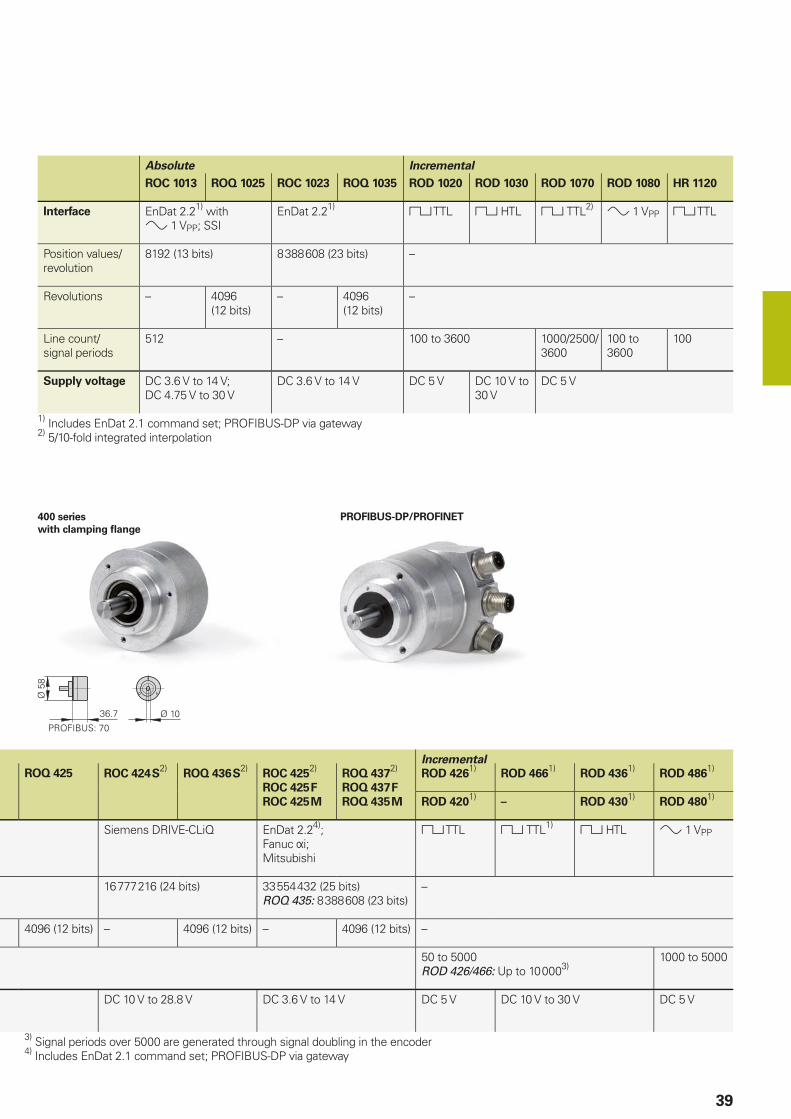
Absolute Incremental
ROC 1013 ROQ 1025 ROC 1023 ROQ 1035 ROD 1020 ROD 1030 ROD 1070 ROD 1080 HR 1120
Interface EnDat 2.21) with 1 VPP; SSI
EnDat 2.21) TTL HTL TTL2) 1 VPP TTL
Position values/revolution
8192 (13 bits) 8 388 608 (23 bits) –
Revolutions – 4096 (12 bits)
– 4096 (12 bits)
–
Line count/signal periods
512 – 100 to 3600 1000/2500/3600
100 to 3600
100
Supply voltage DC 3.6 V to 14 V;DC 4.75 V to 30 V
DC 3.6 V to 14 V DC 5 V DC 10 V to 30 V
DC 5 V
1) Includes EnDat 2.1 command set; PROFIBUS-DP via gateway2) 5/10-fold integrated interpolation
Incremental
ROQ 425 ROC 424 S2)
ROQ 436 S2)
ROC 4252)
ROC 425 F
ROC 425 M
ROQ 4372)
ROQ 437 F
ROQ 435 M
ROD 4261)
ROD 4661)
ROD 4361)
ROD 4861)
ROD 4201)
– ROD 4301)
ROD 4801)
Siemens DRIVE-CLiQ EnDat 2.24);Fanuc i;Mitsubishi
TTL TTL1) HTL 1 VPP
16 777 216 (24 bits) 33 554 432 (25 bits)ROQ 435: 8 388 608 (23 bits)
–
4096 (12 bits) – 4096 (12 bits) – 4096 (12 bits) –
50 to 5000ROD 426/466: Up to 10 0003)
1000 to 5000
DC 10 V to 28.8 V DC 3.6 V to 14 V DC 5 V DC 10 V to 30 V DC 5 V
3) Signal periods over 5000 are generated through signal doubling in the encoder4) Includes EnDat 2.1 command set; PROFIBUS-DP via gateway
ECI/EQI 1300
ERO 1200
ECI/EBI 4000
ERO 1400
ECI/EQI 1100
40
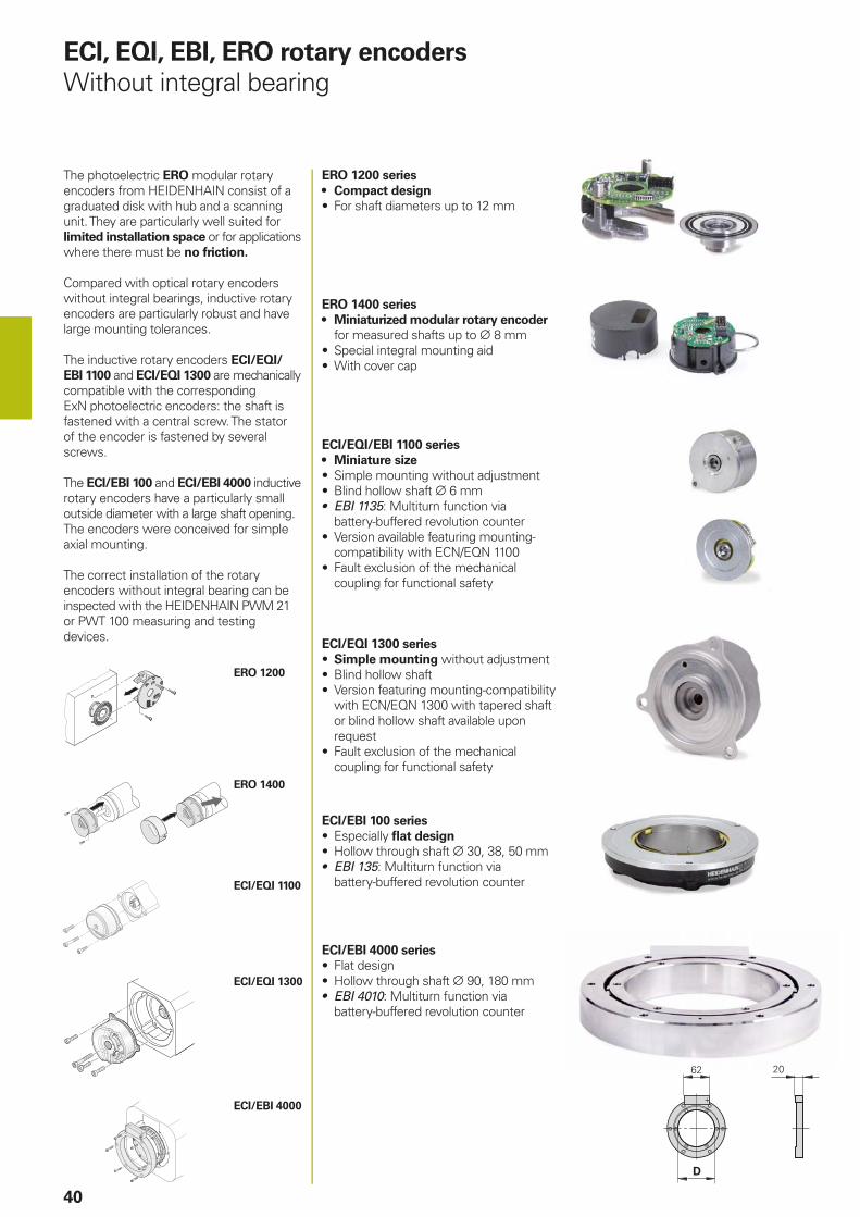
The photoelectric ERO modular rotary encoders from HEIDENHAIN consist of a graduated disk with hub and a scanning unit. They are particularly well suited for limited installation space or for applications where there must be no friction.
Compared with optical rotary encoders without integral bearings, inductive rotary encoders are particularly robust and have large mounting tolerances.
The inductive rotary encoders ECI/EQI/
EBI 1100 and ECI/EQI 1300 are mechanically compatible with the corresponding ExN photoelectric encoders: the shaft is fastened with a central screw. The stator of the encoder is fastened by several screws.
The ECI/EBI 100 and ECI/EBI 4000 inductive rotary encoders have a particularly small outside diameter with a large shaft opening. The encoders were conceived for simple axial mounting.
The correct installation of the rotary encoders without integral bearing can be inspected with the HEIDENHAIN PWM 21 or PWT 100 measuring and testing devices.
ECI/EQI/EBI 1100 series
• Miniature size
• Simple mounting without adjustment• Blind hollow shaft 6 mm• EBI 1135: Multiturn function via
battery-buffered revolution counter• Version available featuring mounting-
compatibility with ECN/EQN 1100• Fault exclusion of the mechanical
coupling for functional safety
ERO 1200 series
• Compact design
• For shaft diameters up to 12 mm
ERO 1400 series
• Miniaturized modular rotary encoder for measured shafts up to 8 mm
• Special integral mounting aid• With cover cap
ECI/EQI 1300 series
• Simple mounting without adjustment• Blind hollow shaft• Version featuring mounting-compatibility
with ECN/EQN 1300 with tapered shaft or blind hollow shaft available upon request
• Fault exclusion of the mechanical coupling for functional safety
ECI/EBI 100 series
• Especially fl at design
• Hollow through shaft 30, 38, 50 mm• EBI 135: Multiturn function via
battery-buffered revolution counter
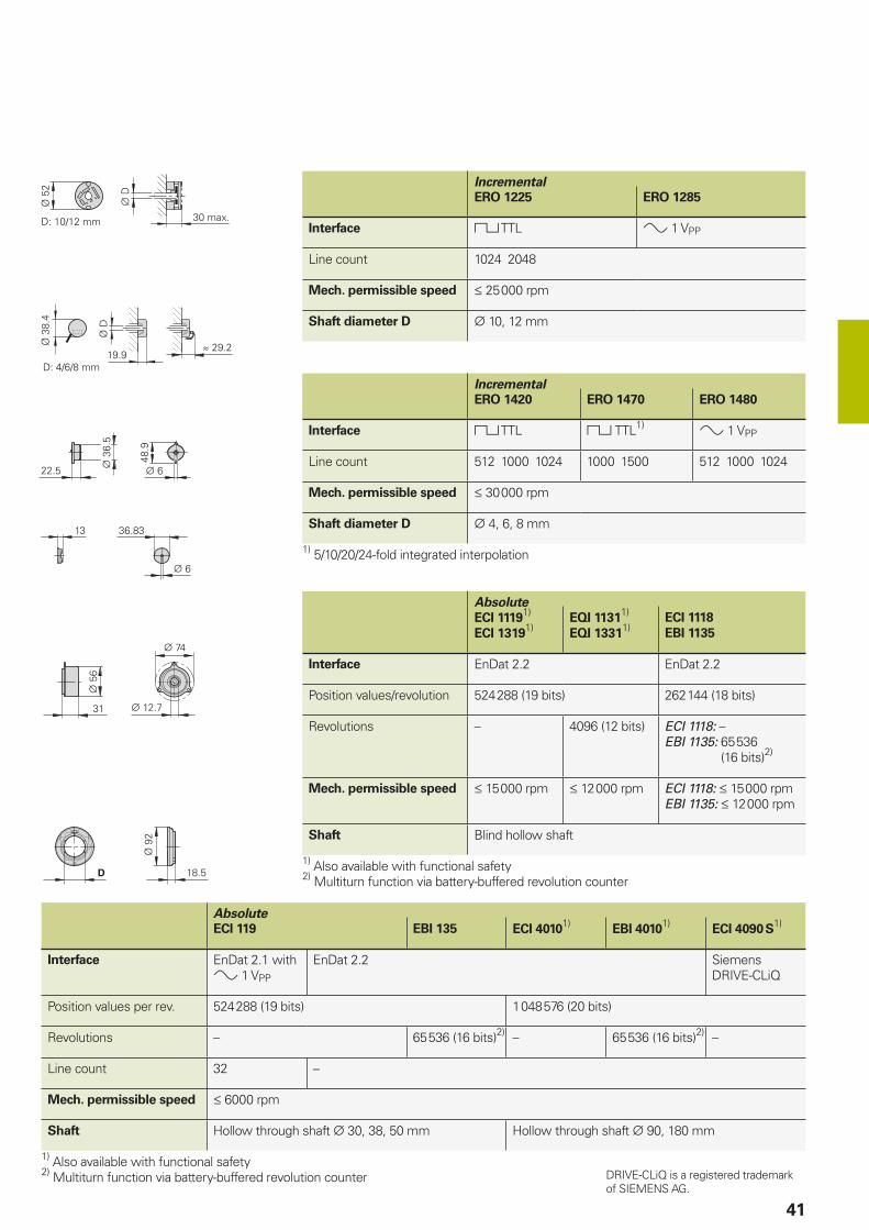
ECI, EQI, EBI, ERO rotary encoders
Without integral bearing
ECI/EBI 4000 series
• Flat design• Hollow through shaft 90, 180 mm• EBI 4010: Multiturn function via
battery-buffered revolution counter
41
Absolute
ECI 11191)
ECI 13191)
EQI 11311)
EQI 13311)
ECI 1118
EBI 1135
Interface EnDat 2.2 EnDat 2.2
Position values/revolution 524 288 (19 bits) 262 144 (18 bits)
Revolutions – 4096 (12 bits) ECI 1118: –EBI 1135: 65 536
(16 bits)2)
Mech. permissible speed 15 000 rpm 12 000 rpm ECI 1118: 15 000 rpmEBI 1135: 12 000 rpm
Shaft Blind hollow shaft
1) Also available with functional safety2) Multiturn function via battery-buffered revolution counter
Incremental
ERO 1225 ERO 1285
Interface TTL 1 VPP
Line count 1024 2048
Mech. permissible speed 25 000 rpm
Shaft diameter D 10, 12 mm
Incremental
ERO 1420 ERO 1470 ERO 1480
Interface TTL TTL1) 1 VPP
Line count 512 1000 1024 1000 1500 512 1000 1024
Mech. permissible speed 30 000 rpm
Shaft diameter D 4, 6, 8 mm
1) 5/10/20/24-fold integrated interpolation
Absolute
ECI 119 EBI 135 ECI 40101)
EBI 40101)
ECI 4090 S1)
Interface EnDat 2.1 with 1 VPP
EnDat 2.2 Siemens DRIVE-CLiQ
Position values per rev. 524 288 (19 bits) 1 048 576 (20 bits)
Revolutions – 65 536 (16 bits)2) – 65 536 (16 bits)2) –
Line count 32 –
Mech. permissible speed 6000 rpm
Shaft Hollow through shaft 30, 38, 50 mm Hollow through shaft 90, 180 mm
1) Also available with functional safety2) Multiturn function via battery-buffered revolution counter DRIVE-CLiQ is a registered trademark
of SIEMENS AG.
42
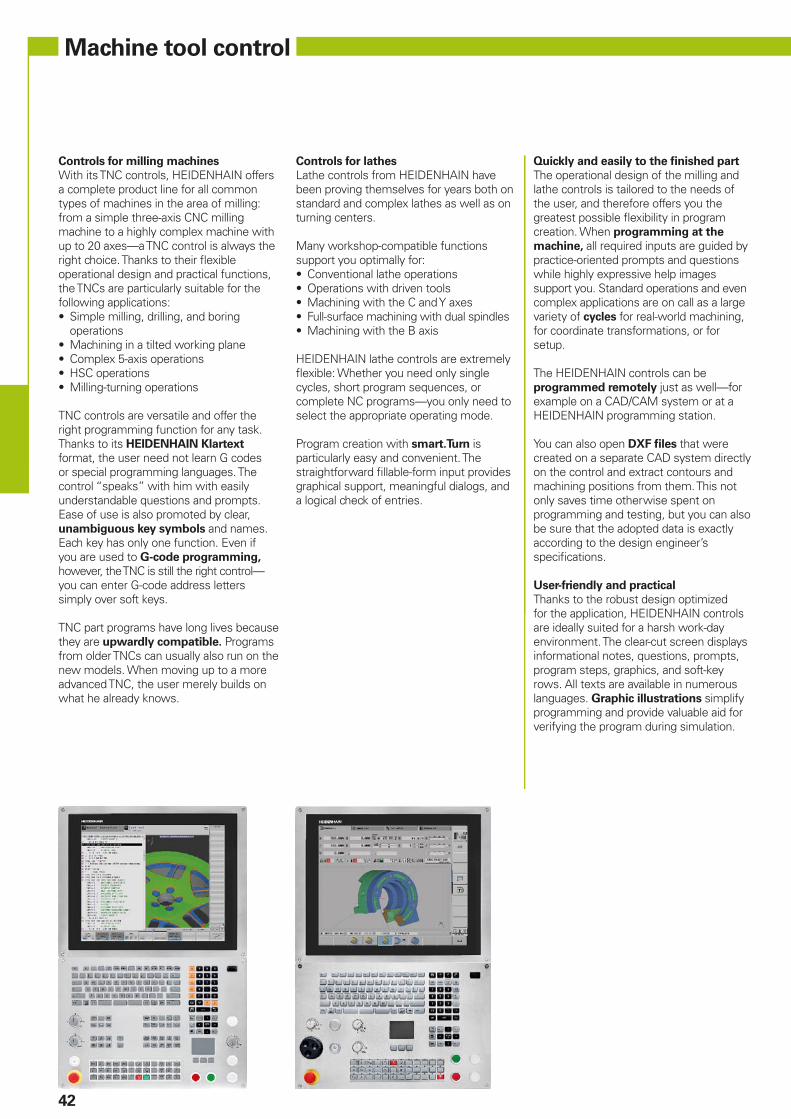
Machine tool control
Controls for milling machines
With its TNC controls, HEIDENHAIN offers a complete product line for all common types of machines in the area of milling: from a simple three-axis CNC milling machine to a highly complex machine with up to 20 axes—a TNC control is always the right choice. Thanks to their fl exible operational design and practical functions, the TNCs are particularly suitable for the following applications:• Simple milling, drilling, and boring
operations• Machining in a tilted working plane• Complex 5-axis operations• HSC operations• Milling-turning operations
TNC controls are versatile and offer the right programming function for any task. Thanks to its HEIDENHAIN Klartext format, the user need not learn G codes or special programming languages. The control “speaks” with him with easily understandable questions and prompts. Ease of use is also promoted by clear, unambiguous key symbols and names. Each key has only one function. Even if you are used to G-code programming, however, the TNC is still the right control—you can enter G-code address letters simply over soft keys.
TNC part programs have long lives because they are upwardly compatible. Programs from older TNCs can usually also run on the new models. When moving up to a more advanced TNC, the user merely builds on what he already knows.
Controls for lathes
Lathe controls from HEIDENHAIN have been proving themselves for years both on standard and complex lathes as well as on turning centers.
Many workshop-compatible functions support you optimally for:• Conventional lathe operations• Operations with driven tools• Machining with the C and Y axes• Full-surface machining with dual spindles• Machining with the B axis
HEIDENHAIN lathe controls are extremely fl exible: Whether you need only single cycles, short program sequences, or complete NC programs—you only need to select the appropriate operating mode.
Program creation with smart.Turn is particularly easy and convenient. The straightforward fi llable-form input provides graphical support, meaningful dialogs, and a logical check of entries.
Quickly and easily to the fi nished part
The operational design of the milling and lathe controls is tailored to the needs of the user, and therefore offers you the greatest possible fl exibility in program creation. When programming at the
machine, all required inputs are guided by practice-oriented prompts and questions while highly expressive help images support you. Standard operations and even complex applications are on call as a large variety of cycles for real-world machining, for coordinate transformations, or for setup.
The HEIDENHAIN controls can be programmed remotely just as well—for example on a CAD/CAM system or at a HEIDENHAIN programming station.
You can also open DXF fi les that were created on a separate CAD system directly on the control and extract contours and machining positions from them. This not only saves time otherwise spent on programming and testing, but you can also be sure that the adopted data is exactly according to the design engineer’s specifi cations.
User-friendly and practical
Thanks to the robust design optimized for the application, HEIDENHAIN controls are ideally suited for a harsh work-day environment. The clear-cut screen displays informational notes, questions, prompts, program steps, graphics, and soft-key rows. All texts are available in numerous languages. Graphic illustrations simplify programming and provide valuable aid for verifying the program during simulation.
43
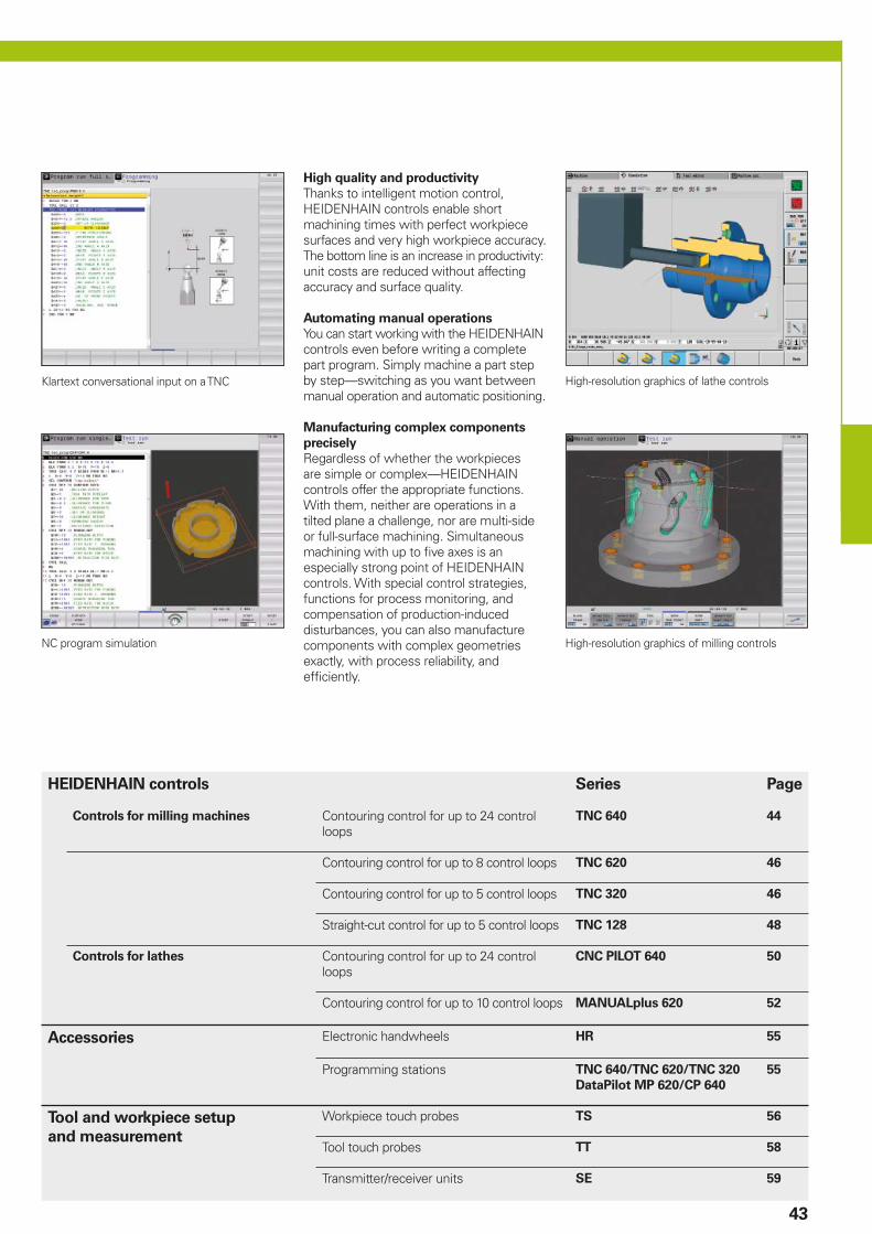
Klartext conversational input on a TNC High-resolution graphics of lathe controls
High-resolution graphics of milling controlsNC program simulation
High quality and productivity
Thanks to intelligent motion control, HEIDENHAIN controls enable short machining times with perfect workpiece surfaces and very high workpiece accuracy. The bottom line is an increase in productivity: unit costs are reduced without affecting accuracy and surface quality.
Automating manual operations
You can start working with the HEIDENHAIN controls even before writing a complete part program. Simply machine a part step by step—switching as you want between manual operation and automatic positioning.
Manufacturing complex components
precisely
Regardless of whether the workpieces are simple or complex—HEIDENHAIN controls offer the appropriate functions. With them, neither are operations in a tilted plane a challenge, nor are multi-side or full-surface machining. Simultaneous machining with up to fi ve axes is an especially strong point of HEIDENHAIN controls. With special control strategies, functions for process monitoring, and compensation of production-induced disturbances, you can also manufacture components with complex geometries exactly, with process reliability, and effi ciently.
HEIDENHAIN controls Series Page
Controls for milling machines Contouring control for up to 24 control loops
TNC 640 44
Contouring control for up to 8 control loops TNC 620 46
Contouring control for up to 5 control loops TNC 320 46
Straight-cut control for up to 5 control loops TNC 128 48
Controls for lathes Contouring control for up to 24 control loops
CNC PILOT 640 50
Contouring control for up to 10 control loops MANUALplus 620 52
Accessories Electronic handwheels HR 55
Programming stations TNC 640/TNC 620/TNC 320
DataPilot MP 620/CP 640
55
Tool and workpiece setup
and measurement
Workpiece touch probes TS 56
Tool touch probes TT 58
Transmitter/receiver units SE 59
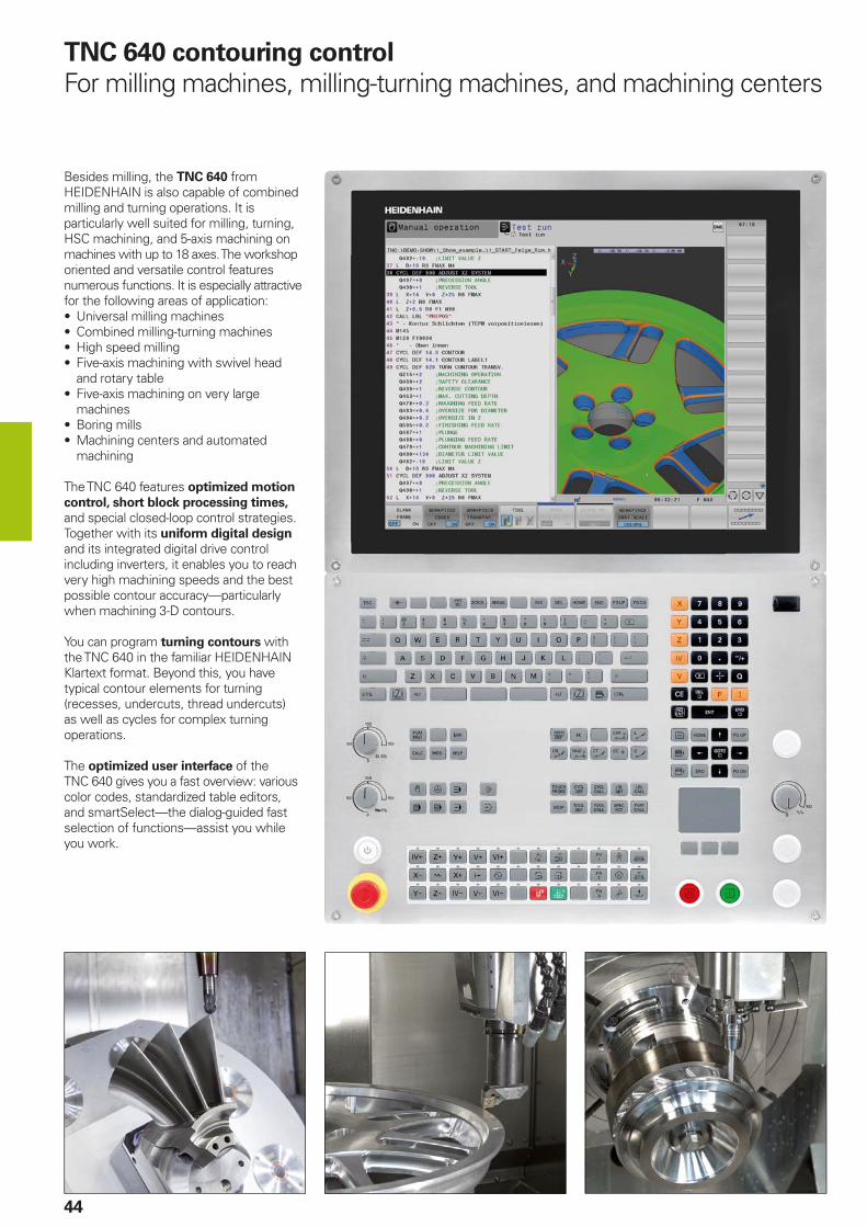
44
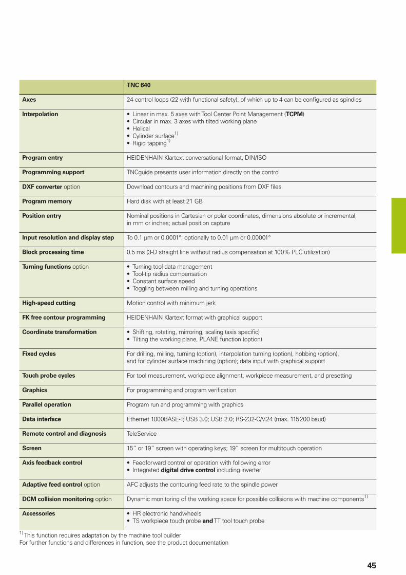
Besides milling, the TNC 640 from HEIDENHAIN is also capable of combined milling and turning operations. It is particularly well suited for milling, turning, HSC machining, and 5-axis machining on machines with up to 18 axes. The workshop oriented and versatile control features numerous functions. It is especially attractive for the following areas of application:• Universal milling machines• Combined milling-turning machines• High speed milling• Five-axis machining with swivel head
and rotary table• Five-axis machining on very large
machines• Boring mills• Machining centers and automated
machining
The TNC 640 features optimized motion
control, short block processing times, and special closed-loop control strategies. Together with its uniform digital design and its integrated digital drive control including inverters, it enables you to reach very high machining speeds and the best possible contour accuracy—particularly when machining 3-D contours.
You can program turning contours with the TNC 640 in the familiar HEIDENHAIN Klartext format. Beyond this, you have typical contour elements for turning (recesses, undercuts, thread undercuts) as well as cycles for complex turning operations.
The optimized user interface of the TNC 640 gives you a fast overview: various color codes, standardized table editors, and smartSelect—the dialog-guided fast selection of functions—assist you while you work.
TNC 640 contouring control
For milling machines, milling-turning machines, and machining centers
45
TNC 640
Axes 24 control loops (22 with functional safety), of which up to 4 can be confi gured as spindles
Interpolation • Linear in max. 5 axes with Tool Center Point Management (TCPM)• Circular in max. 3 axes with tilted working plane• Helical• Cylinder surface1)
• Rigid tapping1)
Program entry HEIDENHAIN Klartext conversational format, DIN/ISO
Programming support TNCguide presents user information directly on the control
DXF converter option Download contours and machining positions from DXF fi les
Program memory Hard disk with at least 21 GB
Position entry Nominal positions in Cartesian or polar coordinates, dimensions absolute or incremental, in mm or inches; actual position capture
Input resolution and display step To 0.1 µm or 0.0001°; optionally to 0.01 µm or 0.00001°
Block processing time 0.5 ms (3-D straight line without radius compensation at 100% PLC utilization)
Turning functions option • Turning tool data management• Tool-tip radius compensation• Constant surface speed• Toggling between milling and turning operations
High-speed cutting Motion control with minimum jerk
FK free contour programming HEIDENHAIN Klartext format with graphical support
Coordinate transformation • Shifting, rotating, mirroring, scaling (axis specifi c)• Tilting the working plane, PLANE function (option)
Fixed cycles For drilling, milling, turning (option), interpolation turning (option), hobbing (option), and for cylinder surface machining (option); data input with graphical support
Touch probe cycles For tool measurement, workpiece alignment, workpiece measurement, and presetting
Graphics For programming and program verifi cation
Parallel operation Program run and programming with graphics
Data interface Ethernet 1000BASE-T; USB 3.0; USB 2.0; RS-232-C/V.24 (max. 115 200 baud)
Remote control and diagnosis TeleService
Screen 15” or 19” screen with operating keys; 19” screen for multitouch operation
Axis feedback control • Feedforward control or operation with following error• Integrated digital drive control including inverter
Adaptive feed control option AFC adjusts the contouring feed rate to the spindle power
DCM collision monitoring option Dynamic monitoring of the working space for possible collisions with machine components1)
Accessories • HR electronic handwheels• TS workpiece touch probe and TT tool touch probe
1) This function requires adaptation by the machine tool builderFor further functions and differences in function, see the product documentation
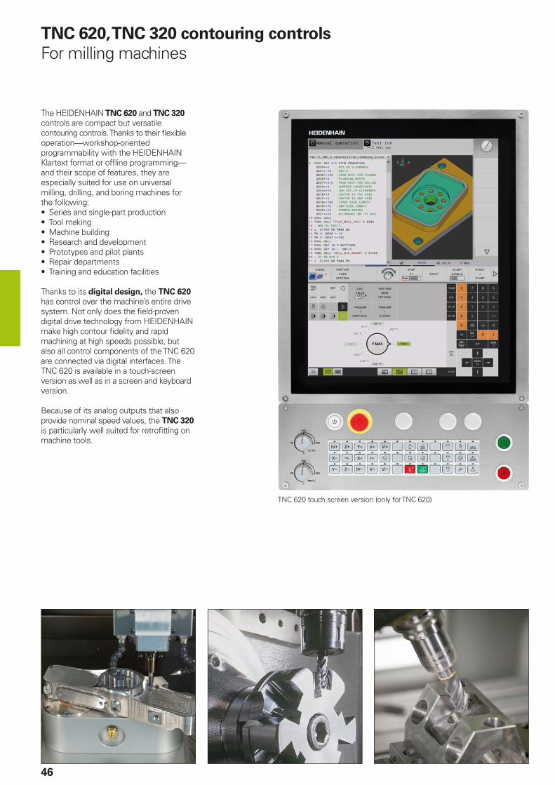
46
TNC 620, TNC 320 contouring controls
For milling machines
The HEIDENHAIN TNC 620 and TNC 320 controls are compact but versatile contouring controls. Thanks to their fl exible operation—workshop-oriented programmability with the HEIDENHAIN Klartext format or offl ine programming—and their scope of features, they are especially suited for use on universal milling, drilling, and boring machines for the following:• Series and single-part production• Tool making• Machine building• Research and development• Prototypes and pilot plants• Repair departments• Training and education facilities
Thanks to its digital design, the TNC 620 has control over the machine’s entire drive system. Not only does the fi eld-proven digital drive technology from HEIDENHAIN make high contour fi delity and rapid machining at high speeds possible, but also all control components of the TNC 620 are connected via digital interfaces. The TNC 620 is available in a touch-screen version as well as in a screen and keyboard version.
Because of its analog outputs that also provide nominal speed values, the TNC 320 is particularly well suited for retrofi tting on machine tools.
TNC 620 touch screen version (only for TNC 620)

47
TNC 620 TNC 320
Axes 8 control loops, of which up to 2 are confi gurable as spindles
6 control loops, of which up to 2 are confi gurable as spindles
Interpolation • Linear: in 4 (optionally 5) main axes• Circular: in 2 (optionally 3) axes• Helical, superimposition of circular and
straight paths• Cylinder surface (option)
• Linear in 4 main axes• Circular in 2 axes• Helical, superimposition of circular and
straight paths• Cylinder surface (option)
Program entry • HEIDENHAIN Klartext conversational format• ISO (input via soft keys or via external USB keyboard)• FK free programming of contours (option with TNC 620)
Programming support TNCguide presents user information directly on the TNC
DXF converter option Download contours and machining positions from DXF fi les
–
Program memory 1.8 GB
Position entry • Positions in Cartesian or polar coordinates• Incremental or absolute dimensions• Display and entry in mm or inches• Actual position capture
Input resolution and display step To 0.1 µm or 0.0001°;optionally to 0.01 µm or 0.000 01°
To 0.1 µm or 0.0001°
Block processing time 1.5 ms 6 ms
Coordinate transformation • Shifting, rotating, mirroring, scaling (axis specifi c)• Tilting the working plane, PLANE function (option)
Fixed cycles
(some optional with the TNC 620)• Drilling, tapping, thread cutting, reaming, and boring• Cycles for hole patterns, facing of fl at surfaces• Clearance and fi nishing of pockets, slots, and studs
Touch probe cycles For tool measurement, workpiece alignment, workpiece measurement, and workpiece presetting (optional for TNC 620)
Graphics For programming and program verifi cation (option with TNC 620); graphic support with cycle programming
Parallel operation Programming during program run, program-run graphics (option with TNC 620)
Data interface Ethernet 1000BASE-T; USB 3.0; USB 2.0; RS-232-C/V.24, and RS-422/V.11 (max. 115 200 baud)
Screen 15” screen with operating keys or 19” screen for multitouch operation (portrait)
15” screen with operating keys
Axis feedback control Feedforward control or operation with following error
Integrated digital drive control for synchronous and asynchronous motors
–
Interfacing to the machine Via integrated programmable logic controller (PLC)
Inputs/outputs with PL 6000 Inputs/outputs expandable with PL 510
Accessories • HR panel-mounted electronic handwheels• TS workpiece touch probe and TT tool touch probe

48
TNC 128 straight-cut control
For milling machines
The TNC 128 from HEIDENHAIN is a compact but versatile straight-cut control for three servo axes and servo spindle. A further servo axis is an option. Thanks to its simple operation and scope of features, it is especially well suited for use on universal milling, drilling, and boring machines for• Series and single-part production• Machine building• Prototypes and pilot plants• Repair departments• Training and education facilities
Because of its analog output that also provides nominal speed values, the TNC 128 is well suited for retrofi tting on machine tools.
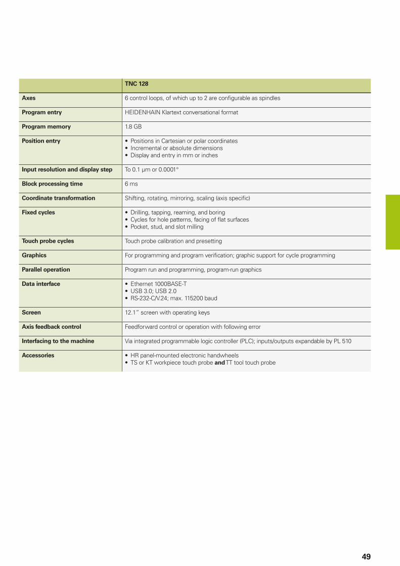
49
TNC 128
Axes 6 control loops, of which up to 2 are confi gurable as spindles
Program entry HEIDENHAIN Klartext conversational format
Program memory 1.8 GB
Position entry • Positions in Cartesian or polar coordinates• Incremental or absolute dimensions• Display and entry in mm or inches
Input resolution and display step To 0.1 µm or 0.0001°
Block processing time 6 ms
Coordinate transformation Shifting, rotating, mirroring, scaling (axis specifi c)
Fixed cycles • Drilling, tapping, reaming, and boring• Cycles for hole patterns, facing of fl at surfaces• Pocket, stud, and slot milling
Touch probe cycles Touch probe calibration and presetting
Graphics For programming and program verifi cation; graphic support for cycle programming
Parallel operation Program run and programming, program-run graphics
Data interface • Ethernet 1000BASE-T• USB 3.0; USB 2.0• RS-232-C/V.24; max. 115200 baud
Screen 12.1” screen with operating keys
Axis feedback control Feedforward control or operation with following error
Interfacing to the machine Via integrated programmable logic controller (PLC); inputs/outputs expandable by PL 510
Accessories • HR panel-mounted electronic handwheels• TS or KT workpiece touch probe and TT tool touch probe
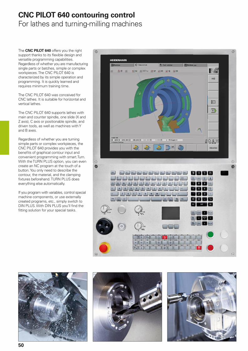
50
CNC PILOT 640 contouring control
For lathes and turning-milling machines
The CNC PILOT 640 offers you the right support thanks to its fl exible design and versatile programming capabilities. Regardless of whether you are manufacturing single parts or batches, simple or complex workpieces. The CNC PILOT 640 is characterized by its simple operation and programming. It is quickly learned and requires minimum training time.
The CNC PILOT 640 was conceived for CNC lathes. It is suitable for horizontal and vertical lathes.
The CNC PILOT 640 supports lathes with main and counter spindle, one slide (X and Z axis), C axis or positionable spindle, and driven tools, as well as machines with Y and B axes.
Regardless of whether you are turning simple parts or complex workpieces, the CNC PILOT 640 provides you with the benefi ts of graphical contour input and convenient programming with smart.Turn. With the TURN PLUS option, you can even create an NC program at the touch of a button. You only need to describe the contour, the material, and the clamping fi xtures beforehand. TURN PLUS does everything else automatically.
If you program with variables, control special machine components, or use externally created programs, etc., simply switch to DIN PLUS. With DIN PLUS you’ll fi nd the fi tting solution for your special tasks.
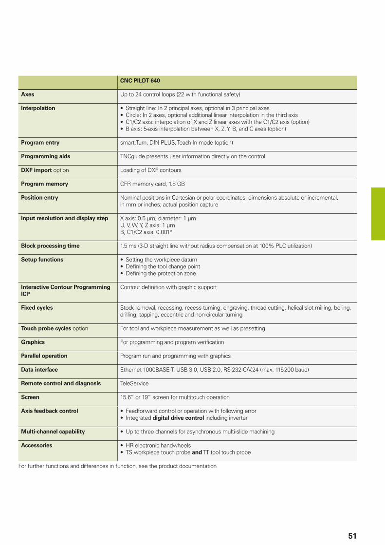
51
CNC PILOT 640
Axes Up to 24 control loops (22 with functional safety)
Interpolation • Straight line: In 2 principal axes, optional in 3 principal axes• Circle: In 2 axes, optional additional linear interpolation in the third axis• C1/C2 axis: interpolation of X and Z linear axes with the C1/C2 axis (option)• B axis: 5-axis interpolation between X, Z, Y, B, and C axes (option)
Program entry smart.Turn, DIN PLUS, Teach-In mode (option)
Programming aids TNCguide presents user information directly on the control
DXF import option Loading of DXF contours
Program memory CFR memory card, 1.8 GB
Position entry Nominal positions in Cartesian or polar coordinates, dimensions absolute or incremental, in mm or inches; actual position capture
Input resolution and display step X axis: 0.5 µm, diameter: 1 µmU, V, W, Y, Z axis: 1 µmB, C1/C2 axis: 0.001°
Block processing time 1.5 ms (3-D straight line without radius compensation at 100% PLC utilization)
Setup functions • Setting the workpiece datum• Defi ning the tool change point• Defi ning the protection zone
Interactive Contour Programming
ICP
Contour defi nition with graphic support
Fixed cycles Stock removal, recessing, recess turning, engraving, thread cutting, helical slot milling, boring, drilling, tapping, eccentric and non-circular turning
Touch probe cycles option For tool and workpiece measurement as well as presetting
Graphics For programming and program verifi cation
Parallel operation Program run and programming with graphics
Data interface Ethernet 1000BASE-T; USB 3.0; USB 2.0; RS-232-C/V.24 (max. 115 200 baud)
Remote control and diagnosis TeleService
Screen 15.6” or 19” screen for multitouch operation
Axis feedback control • Feedforward control or operation with following error• Integrated digital drive control including inverter
Multi-channel capability • Up to three channels for asynchronous multi-slide machining
Accessories • HR electronic handwheels• TS workpiece touch probe and TT tool touch probe
For further functions and differences in function, see the product documentation
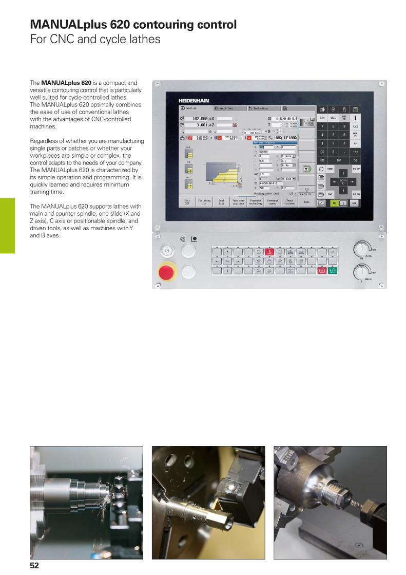
52
The MANUALplus 620 is a compact and versatile contouring control that is particularly well suited for cycle-controlled lathes. The MANUALplus 620 optimally combines the ease of use of conventional lathes with the advantages of CNC-controlled machines.
Regardless of whether you are manufacturing single parts or batches or whether your workpieces are simple or complex, the control adapts to the needs of your company. The MANUALplus 620 is characterized by its simple operation and programming. It is quickly learned and requires minimum training time.
The MANUALplus 620 supports lathes with main and counter spindle, one slide (X and Z axis), C axis or positionable spindle, and driven tools, as well as machines with Y and B axes.
MANUALplus 620 contouring control
For CNC and cycle lathes
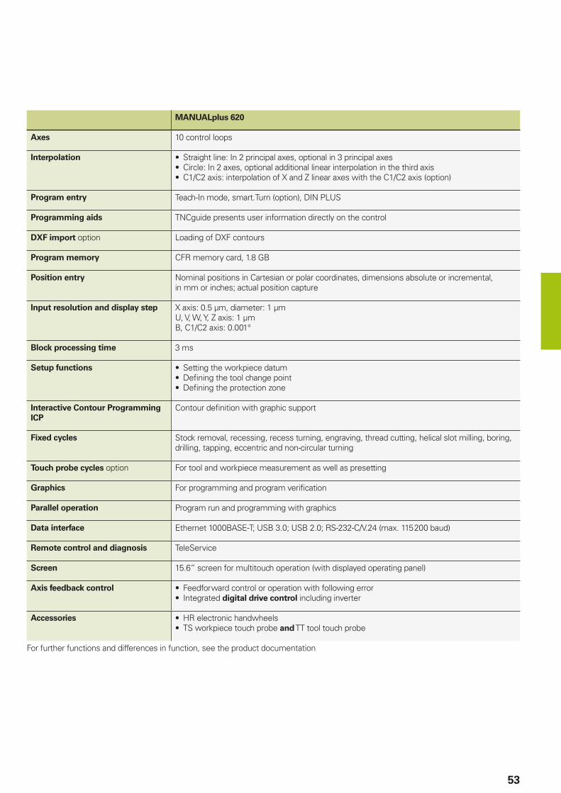
53
MANUALplus 620
Axes 10 control loops
Interpolation • Straight line: In 2 principal axes, optional in 3 principal axes• Circle: In 2 axes, optional additional linear interpolation in the third axis• C1/C2 axis: interpolation of X and Z linear axes with the C1/C2 axis (option)
Program entry Teach-In mode, smart.Turn (option), DIN PLUS
Programming aids TNCguide presents user information directly on the control
DXF import option Loading of DXF contours
Program memory CFR memory card, 1.8 GB
Position entry Nominal positions in Cartesian or polar coordinates, dimensions absolute or incremental, in mm or inches; actual position capture
Input resolution and display step X axis: 0.5 µm, diameter: 1 µmU, V, W, Y, Z axis: 1 µmB, C1/C2 axis: 0.001°
Block processing time 3 ms
Setup functions • Setting the workpiece datum• Defi ning the tool change point• Defi ning the protection zone
Interactive Contour Programming
ICP
Contour defi nition with graphic support
Fixed cycles Stock removal, recessing, recess turning, engraving, thread cutting, helical slot milling, boring, drilling, tapping, eccentric and non-circular turning
Touch probe cycles option For tool and workpiece measurement as well as presetting
Graphics For programming and program verifi cation
Parallel operation Program run and programming with graphics
Data interface Ethernet 1000BASE-T; USB 3.0; USB 2.0; RS-232-C/V.24 (max. 115 200 baud)
Remote control and diagnosis TeleService
Screen 15.6” screen for multitouch operation (with displayed operating panel)
Axis feedback control • Feedforward control or operation with following error• Integrated digital drive control including inverter
Accessories • HR electronic handwheels• TS workpiece touch probe and TT tool touch probe
For further functions and differences in function, see the product documentation
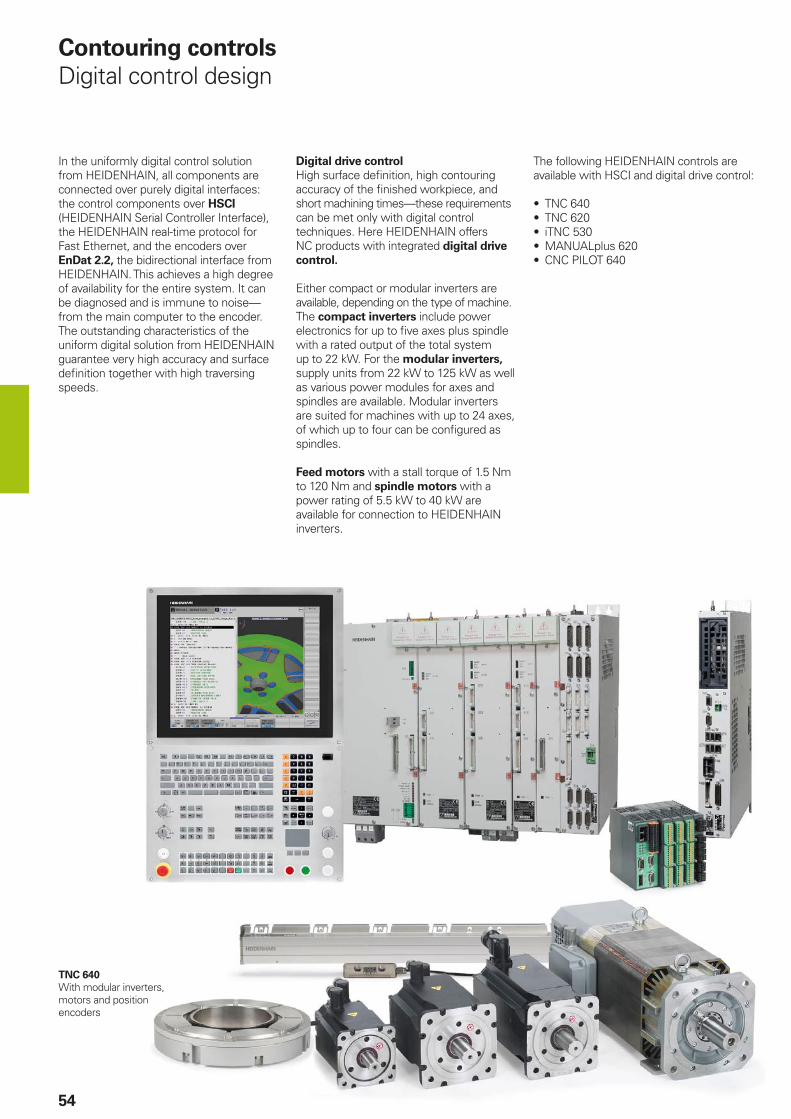
54
Contouring controls
Digital control design
In the uniformly digital control solution from HEIDENHAIN, all components are connected over purely digital interfaces: the control components over HSCI (HEIDENHAIN Serial Controller Interface), the HEIDENHAIN real-time protocol for Fast Ethernet, and the encoders over EnDat 2.2, the bidirectional interface from HEIDENHAIN. This achieves a high degree of availability for the entire system. It can be diagnosed and is immune to noise—from the main computer to the encoder. The outstanding characteristics of the uniform digital solution from HEIDENHAIN guarantee very high accuracy and surface defi nition together with high traversing speeds.
TNC 640
With modular inverters, motors and position encoders
The following HEIDENHAIN controls are available with HSCI and digital drive control:
• TNC 640• TNC 620• iTNC 530• MANUALplus 620• CNC PILOT 640
Digital drive control
High surface defi nition, high contouring accuracy of the fi nished workpiece, and short machining times—these requirements can be met only with digital control techniques. Here HEIDENHAIN offers NC products with integrated digital drive
control.
Either compact or modular inverters are available, depending on the type of machine. The compact inverters include power electronics for up to fi ve axes plus spindle with a rated output of the total system up to 22 kW. For the modular inverters, supply units from 22 kW to 125 kW as well as various power modules for axes and spindles are available. Modular inverters are suited for machines with up to 24 axes, of which up to four can be confi gured as spindles.
Feed motors with a stall torque of 1.5 Nm to 120 Nm and spindle motors with a power rating of 5.5 kW to 40 kW are available for connection to HEIDENHAIN inverters.
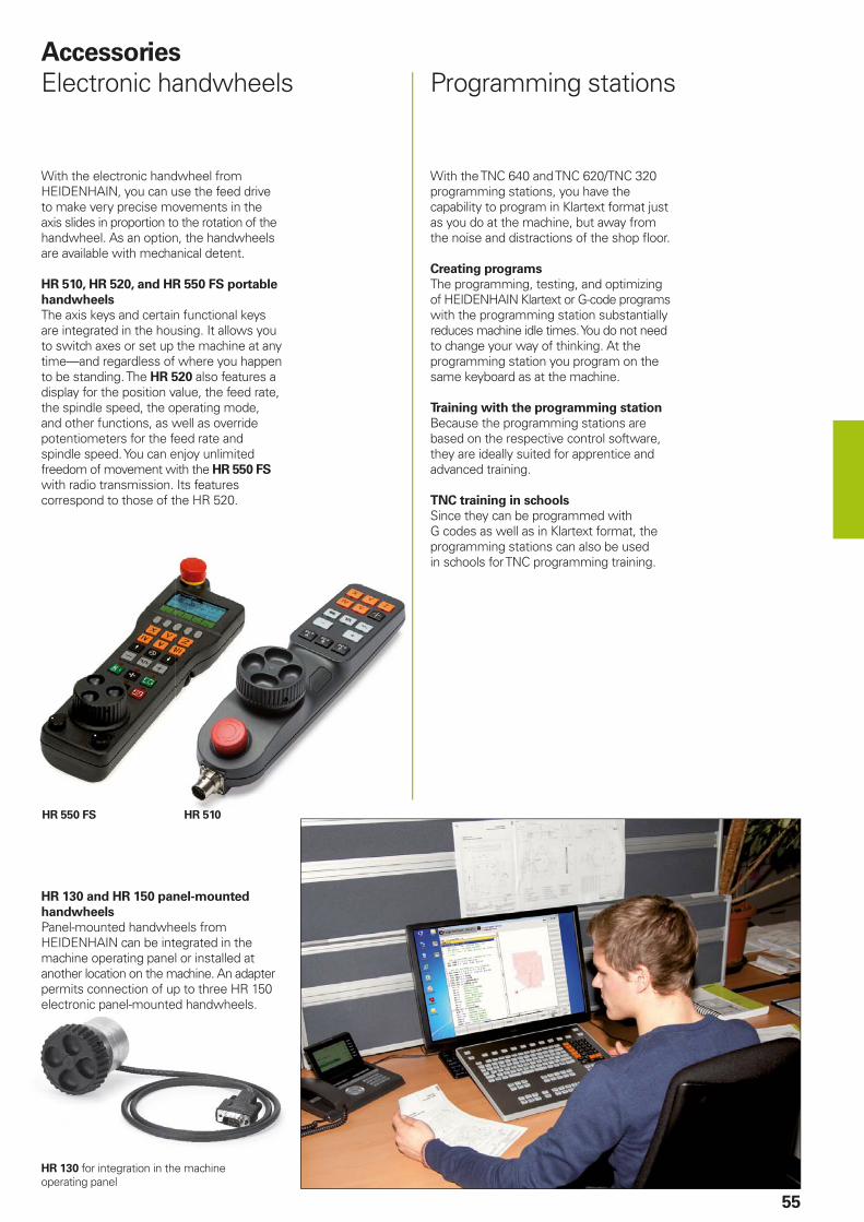
HR 510HR 550 FS
55
Accessories
Electronic handwheels Programming stations
With the electronic handwheel from HEIDENHAIN, you can use the feed drive to make very precise movements in the axis slides in proportion to the rotation of the handwheel. As an option, the handwheels are available with mechanical detent.
HR 510, HR 520, and HR 550 FS portable
handwheels
The axis keys and certain functional keys are integrated in the housing. It allows you to switch axes or set up the machine at any time—and regardless of where you happen to be standing. The HR 520 also features a display for the position value, the feed rate, the spindle speed, the operating mode, and other functions, as well as override potentiometers for the feed rate and spindle speed. You can enjoy unlimited freedom of movement with the HR 550 FS with radio transmission. Its features correspond to those of the HR 520.
With the TNC 640 and TNC 620/TNC 320 programming stations, you have the capability to program in Klartext format just as you do at the machine, but away from the noise and distractions of the shop fl oor.
Creating programs
The programming, testing, and optimizing of HEIDENHAIN Klartext or G-code programs with the programming station substantially reduces machine idle times. You do not need to change your way of thinking. At the programming station you program on the same keyboard as at the machine.
Training with the programming station
Because the programming stations are based on the respective control software, they are ideally suited for apprentice and advanced training.
TNC training in schools
Since they can be programmed with G codes as well as in Klartext format, the programming stations can also be used in schools for TNC programming training.
HR 130 and HR 150 panel-mounted
handwheels
Panel-mounted handwheels from HEIDENHAIN can be integrated in the machine operating panel or installed at another location on the machine. An adapter permits connection of up to three HR 150 electronic panel-mounted handwheels.
HR 130 for integration in the machine operating panel
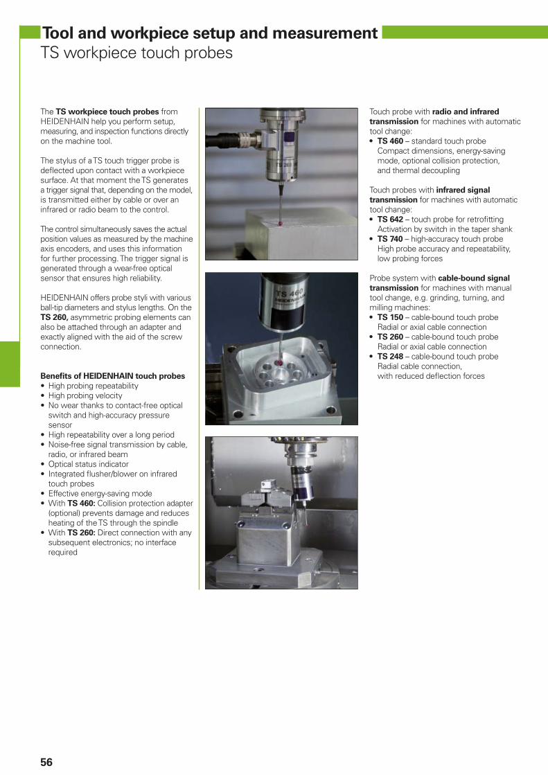
56
The TS workpiece touch probes from HEIDENHAIN help you perform setup, measuring, and inspection functions directly on the machine tool.
The stylus of a TS touch trigger probe is defl ected upon contact with a workpiece surface. At that moment the TS generates a trigger signal that, depending on the model, is transmitted either by cable or over an infrared or radio beam to the control.
The control simultaneously saves the actual position values as measured by the machine axis encoders, and uses this information for further processing. The trigger signal is generated through a wear-free optical sensor that ensures high reliability.
HEIDENHAIN offers probe styli with various ball-tip diameters and stylus lengths. On the TS 260, asymmetric probing elements can also be attached through an adapter and exactly aligned with the aid of the screw connection.
Benefi ts of HEIDENHAIN touch probes
• High probing repeatability• High probing velocity• No wear thanks to contact-free optical
switch and high-accuracy pressuresensor
• High repeatability over a long period• Noise-free signal transmission by cable,
radio, or infrared beam• Optical status indicator• Integrated fl usher/blower on infrared
touch probes• Effective energy-saving mode• With TS 460: Collision protection adapter
(optional) prevents damage and reducesheating of the TS through the spindle
• With TS 260: Direct connection with anysubsequent electronics; no interfacerequired
Tool and workpiece setup and measurement
TS workpiece touch probes
Touch probe with radio and infrared
transmission for machines with automatic tool change:• TS 460 – standard touch probe
Compact dimensions, energy-savingmode, optional collision protection,and thermal decoupling
Touch probes with infrared signal
transmission for machines with automatic tool change:• TS 642 – touch probe for retrofi tting
Activation by switch in the taper shank• TS 740 – high-accuracy touch probe
High probe accuracy and repeatability,low probing forces
Probe system with cable-bound signal
transmission for machines with manual tool change, e.g. grinding, turning, and milling machines:• TS 150 – cable-bound touch probe
Radial or axial cable connection• TS 260 – cable-bound touch probe
Radial or axial cable connection• TS 248 – cable-bound touch probe
Radial cable connection,with reduced defl ection forces
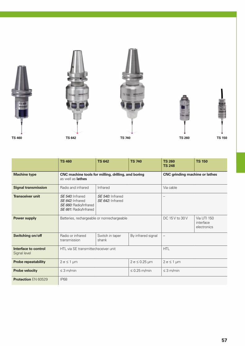
TS 460 TS 642 TS 260 TS 150TS 740
57
TS 460 TS 642 TS 740 TS 260
TS 248
TS 150
Machine type CNC machine tools for milling, drilling, and boring as well as lathes
CNC grinding machine or lathes
Signal transmission Radio and infrared Infrared Via cable
Transceiver unit SE 540: InfraredSE 642: InfraredSE 660: Radio/InfraredSE 661: Radio/Infrared
SE 540: InfraredSE 642: Infrared
–
Power supply Batteries, rechargeable or nonrechargeable DC 15 V to 30 V Via UTI 150 interface electronics
Switching on/off Radio or infrared transmission
Switch in taper shank
By infrared signal –
Interface to control
Signal levelHTL via SE transmitter/receiver unit HTL
Probe repeatability 2 1 µm 2 0.25 µm 2 1 µm
Probe velocity 3 m/min 0.25 m/min 3 m/min
Protection EN 60529 IP68
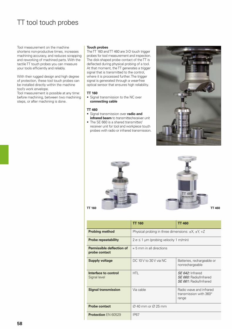
TT 160 TT 460
58
TT 160 TT 460
Probing method Physical probing in three dimensions: ±X, ±Y, +Z
Probe repeatability 2 1 µm (probing velocity 1 m/min)
Permissible defl ection of
probe contact
5 mm in all directions
Supply voltage DC 10 V to 30 V via NC Batteries, rechargeable or nonrechargeable
Interface to control
Signal levelHTL SE 642: Infrared
SE 660: Radio/InfraredSE 661: Radio/Infrared
Signal transmission Via cable Radio wave and infrared transmission with 360° range
Probe contact 40 mm or 25 mm
Protection EN 60529 IP67
TT tool touch probes
Tool measurement on the machine shortens non-productive times, increases machining accuracy, and reduces scrapping and reworking of machined parts. With the tactile TT touch probes you can measure your tools effi ciently and reliably.
With their rugged design and high degree of protection, these tool touch probes can be installed directly within the machine tool’s work envelope.Tool measurement is possible at any time: before machining, between two machining steps, or after machining is done.
Touch probes
The TT 160 and TT 460 are 3-D touch trigger probes for tool measurement and inspection. The disk-shaped probe contact of the TT is defl ected during physical probing of a tool. At that moment, the TT generates a trigger signal that is transmitted to the control, where it is processed further. The trigger signal is generated through a wear-free optical sensor that ensures high reliability.
TT 160
• Signal transmission to the NC overconnecting cable
TT 460
• Signal transmission over radio and
infrared beam to transmitter/receiver unit• The SE 660 is a shared transmitter/
receiver unit for tool and workpiece touchprobes with radio or infrared transmission.
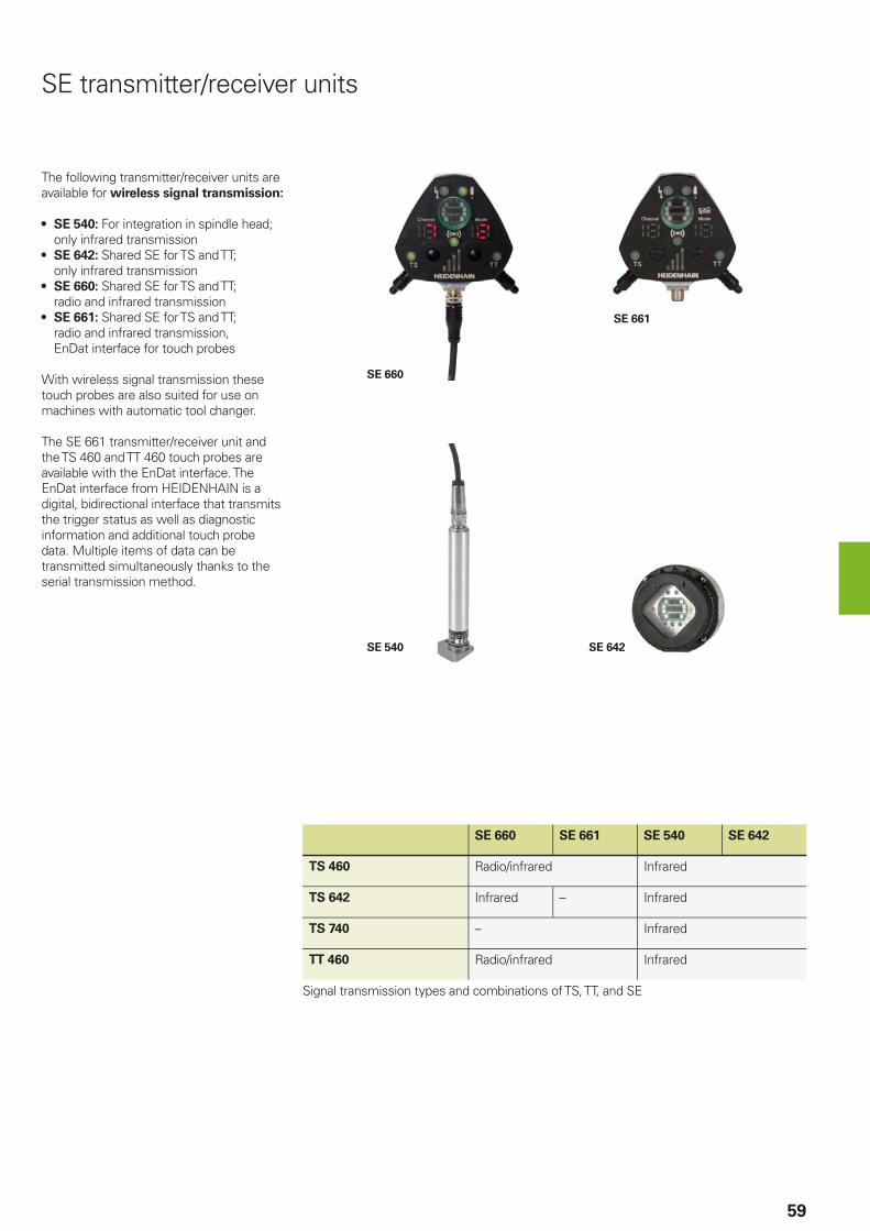
SE 660
SE 661
SE 540 SE 642
59
SE 660 SE 661 SE 540 SE 642
TS 460 Radio/infrared Infrared
TS 642 Infrared – Infrared
TS 740 – Infrared
TT 460 Radio/infrared Infrared
Signal transmission types and combinations of TS, TT, and SE
The following transmitter/receiver units are available for wireless signal transmission:
• SE 540: For integration in spindle head; only infrared transmission
• SE 642: Shared SE for TS and TT; only infrared transmission
• SE 660: Shared SE for TS and TT; radio and infrared transmission
• SE 661: Shared SE for TS and TT; radio and infrared transmission, EnDat interface for touch probes
With wireless signal transmission these touch probes are also suited for use on machines with automatic tool changer.
The SE 661 transmitter/receiver unit and the TS 460 and TT 460 touch probes are available with the EnDat interface. The EnDat interface from HEIDENHAIN is a digital, bidirectional interface that transmits the trigger status as well as diagnostic information and additional touch probe data. Multiple items of data can be transmitted simultaneously thanks to the serial transmission method.
SE transmitter/receiver units
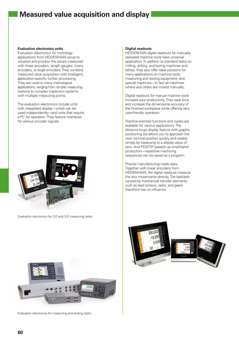
60
Measured value acquisition and display
Evaluation electronics units
Evaluation electronics for metrology applications from HEIDENHAIN serve to visualize and process the values measured with linear encoders, length gauges, rotary encoders, or angle encoders. They combine measured value acquisition with intelligent, application-specifi c further processing. They are used in many metrological applications, ranging from simple measuring stations to complex inspection systems with multiple measuring points.
The evaluation electronics include units with integrated display—which can be used independently—and units that require a PC for operation. They feature interfaces for various encoder signals.
Digital readouts
HEIDENHAIN digital readouts for manually operated machine tools have universal application: In addition to standard tasks on milling, drilling, and boring machines and lathes, they also offer ideal solutions for many applications on machine tools, measuring and testing equipment, and special machines—in fact all machines where axis slides are moved manually.
Digital readouts for manual machine tools increase your productivity. They save time and increase the dimensional accuracy of the fi nished workpiece while offering very user-friendly operation.
Practice-oriented functions and cycles are available for various applications. The distance-to-go display feature with graphic positioning aid allows you to approach the next nominal position quickly and reliably simply by traversing to a display value of zero. And POSITIP speeds up small-batch production—repetitive machining sequences can be saved as a program.
Precise manufacturing made easy:Together with linear encoders from HEIDENHAIN, the digital readouts measure the axis movements directly. The backlash caused by mechanical transfer elements such as lead screws, racks, and gears therefore has no infl uence.
Evaluation electronics for 2-D and 3-D measuring tasks
Evaluation electronics for measuring and testing tasks
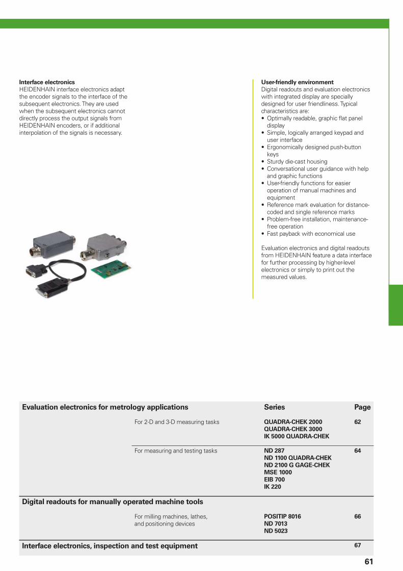
61
Interface electronics
HEIDENHAIN interface electronics adapt the encoder signals to the interface of the subsequent electronics. They are used when the subsequent electronics cannot directly process the output signals from HEIDENHAIN encoders, or if additional interpolation of the signals is necessary.
User-friendly environment
Digital readouts and evaluation electronics with integrated display are specially designed for user friendliness. Typical characteristics are:• Optimally readable, graphic fl at panel
display• Simple, logically arranged keypad and
user interface• Ergonomically designed push-button
keys• Sturdy die-cast housing• Conversational user guidance with help
and graphic functions• User-friendly functions for easier
operation of manual machines and equipment
• Reference mark evaluation for distance-coded and single reference marks
• Problem-free installation, maintenance-free operation
• Fast payback with economical use
Evaluation electronics and digital readouts from HEIDENHAIN feature a data interface for further processing by higher-level electronics or simply to print out the measured values.
Evaluation electronics for metrology applications Series Page
For 2-D and 3-D measuring tasks QUADRA-CHEK 2000
QUADRA-CHEK 3000
IK 5000 QUADRA-CHEK
62
For measuring and testing tasks ND 287
ND 1100 QUADRA-CHEK
ND 2100 G GAGE-CHEK
MSE 1000
EIB 700
IK 220
64
Digital readouts for manually operated machine tools
For milling machines, lathes, and positioning devices
POSITIP 8016
ND 7013
ND 5023
66
Interface electronics, inspection and test equipment 67
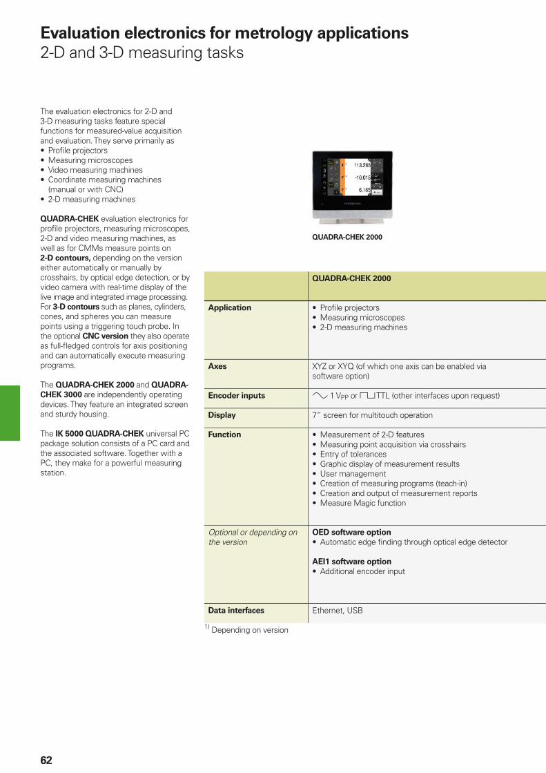
QUADRA-CHEK 2000
62
The evaluation electronics for 2-D and 3-D measuring tasks feature special functions for measured-value acquisition and evaluation. They serve primarily as• Profi le projectors• Measuring microscopes• Video measuring machines• Coordinate measuring machines
(manual or with CNC)• 2-D measuring machines
QUADRA-CHEK evaluation electronics for profi le projectors, measuring microscopes, 2-D and video measuring machines, as well as for CMMs measure points on 2-D contours, depending on the version either automatically or manually by crosshairs, by optical edge detection, or by video camera with real-time display of the live image and integrated image processing. For 3-D contours such as planes, cylinders, cones, and spheres you can measure points using a triggering touch probe. In the optional CNC version they also operate as full-fl edged controls for axis positioning and can automatically execute measuring programs.
The QUADRA-CHEK 2000 and QUADRA-
CHEK 3000 are independently operating devices. They feature an integrated screen and sturdy housing.
The IK 5000 QUADRA-CHEK universal PC package solution consists of a PC card and the associated software. Together with a PC, they make for a powerful measuring station.
Evaluation electronics for metrology applications
2-D and 3-D measuring tasks
QUADRA-CHEK 2000
Application • Profi le projectors• Measuring microscopes• 2-D measuring machines
Axes XYZ or XYQ (of which one axis can be enabled via software option)
Encoder inputs 1 VPP or TTL (other interfaces upon request)
Display 7” screen for multitouch operation
Function • Measurement of 2-D features• Measuring point acquisition via crosshairs• Entry of tolerances• Graphic display of measurement results• User management• Creation of measuring programs (teach-in)• Creation and output of measurement reports• Measure Magic function
Optional or depending on the version
OED software option
• Automatic edge fi nding through optical edge detector
AEI1 software option
• Additional encoder input
Data interfaces Ethernet, USB
1) Depending on version

IK 5000QUADRA-CHEK 3000
63
QUADRA-CHEK 3000 IK 5000
QUADRA-CHEK
• Profi le projectors• Measuring microscopes• 2-D measuring machines• Video measuring machines
• Profi le projectors• Measuring microscopes• Video measuring machines• Coordinate measuring machines• Multi-sensor measuring machines
XYZQ (of which two axes can be enabled via software option) XYQ, XYZ, or XYZQ1)
12.1” screen for multitouch operation By PC screen
• Measurement of 2-D features• Measuring point acquisition via crosshairs• Entry of tolerances• Graphic display of measurement results• Creation of measuring programs (teach-in)• Report generator• Import and export functions for CAD and measured data• Nominal-to-actual comparison for 2-D free-form contours
from a CAD model
AEI1 software option
• Additional encoder input
VED software option
• Video edge detection and live image display• Image archiving• Light control
• Measurement of 3-D features• Automatic edge fi nding through optical edge detector• Video edge detection and live image display• Image archiving• Point measurement by touch probe (also TP 200)• CNC axis control and autofocus• Zoom and light control
PCIe (PC interface)
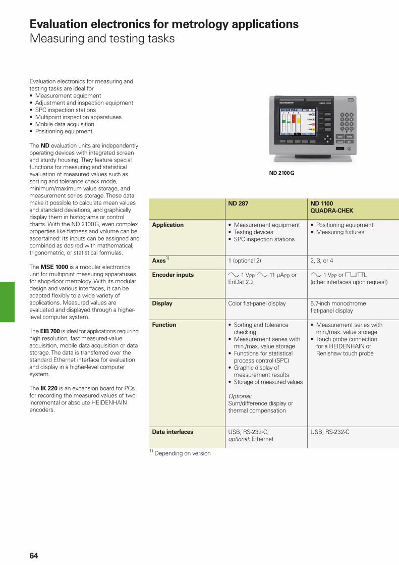
ND 2100 G
64
ND 287 ND 1100
QUADRA-CHEK
Application • Measurement equipment• Testing devices• SPC inspection stations
• Positioning equipment• Measuring fi xtures
Axes1) 1 (optional 2) 2, 3, or 4
Encoder inputs 1 VPP, 11 µAPP, or EnDat 2.2
1 VPP or TTL (other interfaces upon request)
Display Color fl at-panel display 5.7-inch monochrome fl at-panel display
Function • Sorting and tolerance checking
• Measurement series with min./max. value storage
• Functions for statistical process control (SPC)
• Graphic display of measurement results
• Storage of measured values
Optional:Sum/difference display or thermal compensation
• Measurement series with min./max. value storage
• Touch probe connection for a HEIDENHAIN or Renishaw touch probe
Data interfaces USB; RS-232-C;optional: Ethernet
USB; RS-232-C
1) Depending on version
Evaluation electronics for measuring and testing tasks are ideal for • Measurement equipment• Adjustment and inspection equipment• SPC inspection stations• Multipoint inspection apparatuses• Mobile data acquisition• Positioning equipment
The ND evaluation units are independently operating devices with integrated screen and sturdy housing. They feature special functions for measuring and statistical evaluation of measured values such as sorting and tolerance check mode, minimum/maximum value storage, and measurement series storage. These data make it possible to calculate mean values and standard deviations, and graphically display them in histograms or control charts. With the ND 2100 G, even complex properties like fl atness and volume can be ascertained: its inputs can be assigned and combined as desired with mathematical, trigonometric, or statistical formulas.
The MSE 1000 is a modular electronics unit for multipoint measuring apparatuses for shop-fl oor metrology. With its modular design and various interfaces, it can be adapted fl exibly to a wide variety of applications. Measured values are evaluated and displayed through a higher-level computer system.
The EIB 700 is ideal for applications requiring high resolution, fast measured-value acquisition, mobile data acquisition or data storage. The data is transferred over the standard Ethernet interface for evaluation and display in a higher-level computer system.
The IK 220 is an expansion board for PCs for recording the measured values of two incremental or absolute HEIDENHAIN encoders.
Evaluation electronics for metrology applications
Measuring and testing tasks
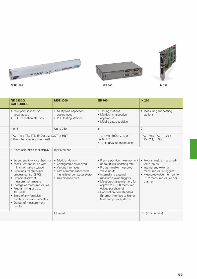
MSE 1000 EIB 700 IK 220
65
ND 2100 G
GAGE-CHEK
MSE 1000 EIB 700 IK 220
• Multipoint inspection apparatuses
• SPC inspection stations
• Multipoint inspection apparatuses
• PLC testing stations
• Testing stations• Multipoint inspection
apparatuses• Mobile data acquisition
• Measuring and testing stations
4 or 8 Up to 250 4 2
1 VPP, TTL, EnDat 2.2, LVDT or HBT(other interfaces upon request)
1 VPP, EnDat 2.1, or EnDat 2.2( 11 µAPP upon request)
1 VPP, 11 µAPP, EnDat 2.1, or SSI
5.7-inch color fl at-panel display By PC screen
• Sorting and tolerance checking• Measurement series with
min./max. value storage• Functions for statistical
process control (SPC)• Graphic display of
measurement results• Storage of measured values• Programming of up to
100 parts• Entry of any formulas,
combinations and variables• Output of measurement
results
• Modular design• Confi gurable as desired• Various interfaces• Fast communication with
higher-level computer system• Universal outputs
• Precise position measurement up to 50 kHz updating rate
• Programmable measured-value inputs
• Internal and external measured-value triggers
• Measured-value memory for approx. 250 000 measured values per channel
• Connection over standard Ethernet interface to higher-level computer systems
• Programmable measured-value inputs
• Internal and external measured-value triggers
• Measured-value memory for 8192 measured values per channel
Ethernet PCI (PC interface)
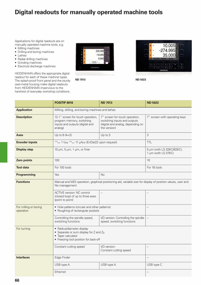
ND 7013 ND 5023
66
Applications for digital readouts are on manually operated machine tools, e.g.• Milling machines• Drilling and boring machines• Lathes• Radial drilling machines• Grinding machines• Electrical discharge machines
HEIDENHAIN offers the appropriate digital readout for each of these machine types. The splash-proof front panel and the sturdy cast-metal housing make digital readouts from HEIDENHAIN impervious to the harshest of everyday workshop conditions.
Digital readouts for manually operated machine tools
POSITIP 8016 ND 7013 ND 5023
Application Milling, drilling, and boring machines and lathes
Description 12.1” screen for touch operation, program memory, switching inputs and outputs (digital and analog)
7” screen for touch operation, switching inputs and outputs (digital and analog, depending on the version)
7” screen with operating keys
Axes Up to 6 (4+2) Up to 3 3
Encoder inputs 1 VPP, 11 µAPP (EnDat22 upon request) TTL
Display step 10 µm, 5 µm, 1 µm, or fi ner 5 µm (with LS 328 C/628 C), 1 µm (with LS 378 C)
Zero points 100 10
Tool data For 100 tools For 16 tools
Programming Yes No
Functions Manual and MDI operation, graphical positioning aid, variable size for display of position values, user and fi le management
ACTIVE version: NC control (closed loop) of up to three axes (point to point)
– –
For milling or boring operation
• Hole patterns (circular and other patterns)• Roughing of rectangular pockets
–
Controlling the spindle speed, switching functions
I/O version: Controlling the spindle speed, switching functions
–
For turning • Radius/diameter display• Separate or sum display for Z and Z0• Taper calculator• Freezing tool position for back-off
Constant cutting speed I/O version:Constant cutting speed
–
Interfaces Edge Finder –
USB type A USB type A USB type C
Ethernet –

67
Interface electronics, inspection and test equipment
HEIDENHAIN interface electronics are available in various mechanical designs:• Box design• Plug design• Version for integration• Top-hat rail design
Plug design
Interface electronics
Interface electronics from HEIDENHAIN adapt the encoder signals to the interface of the subsequent electronics, for example:
Incremental signals 1 VPP > TTL 11 µAPP > TTL
Incremental signals > position values 1 VPP > EnDat 1 VPP > Fanuc Serial Interface 1 VPP > Mitsubishi high speed
Interface
Position valuesEnDat > DRIVE-CLiQEnDat > Yaskawa Serial InterfaceEnDat > PROFIBUS-DPEnDat > PROFINET
In addition to signal conversion, the sinusoidal encoder signals are also interpolated in the interface electronics. This permits fi ner measuring steps and, as a result, higher control quality and better positioning behavior.
Some interface electronics have an integrated counting function. Starting from the last set reference point, an absolute position value is generated when the reference mark is traversed, and it is output to the subsequent electronics.
PWM 21 inspection device with included ATS adjusting and testing software
Inspection and testing devices from
HEIDENHAIN
HEIDENHAIN encoders provide all of the information necessary for commissioning, monitoring, and diagnostics. HEIDENHAIN offers the appropriate PWM inspection devices and PWT testing devices for encoder adjustment and analysis. The PWM inspection devices can be used universally. They have low measuring tolerances and can be calibrated.
Testing devices have larger measuring tolerances and fewer available functions, and cannot be calibrated.
HEIDENHAIN encoders can usually be connected directly or via interface electronics to a number of different subsequent electronics.
HEIDENHAIN therefore offers encoders and interface electronics with various interfaces. The testing and inspection devices from HEIDENHAIN also support various interfaces, which makes their application more fl exible (see overview for the PWM 21 and PWT 100).
PWT 100 test device for mobile application
Encoder input PWM 21 PWT 100
EnDat 2.1 4 4
EnDat 2.2 4 4
DRIVE-CLiQ 4 –
Fanuc Serial Interface
4 4
Mitsubishi high speed interface
4 4
Yaskawa Serial Interface
4 4
Panasonic Serial Interface
4 4
SSI 4 –
1VPP/TTL/11 µAPP 4 4
HTL (via signal adapter)
4 –
DRIVE-CLiQ is a registered trademark of SIEMENS AG.
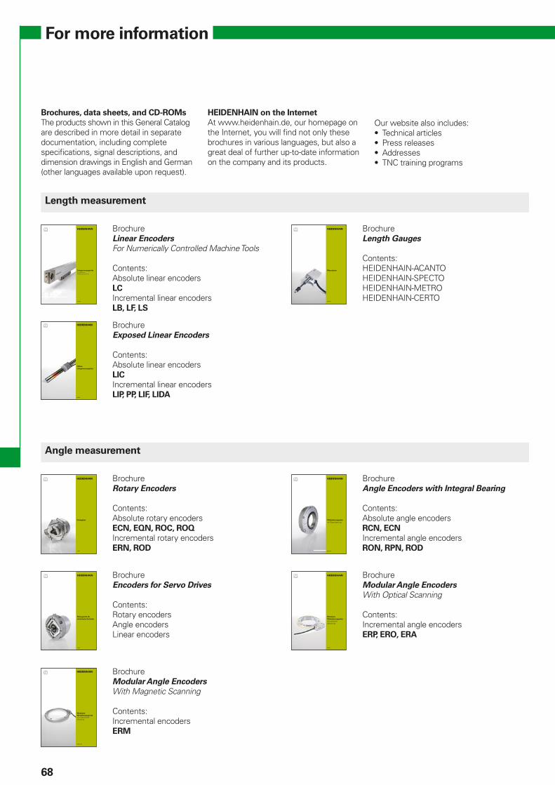
Juni 2017
Längenmessgerätefür gesteuerte Werkzeugmaschinen
April 2017
Messtaster
11/2017
Drehgeber
März 2015
Winkelmessgeräte
mit Eigenlagerung
Oktober 2015
Modulare
Winkelmessgerätemit magnetischer Abtastung
11/2017
Messgeräte für
elektrische Antriebe
09/2017
Modulare
Winkelmessgeräte
mit optischer Abtastung
04/2018
Offene
Längenmessgeräte
68
For more information
Brochures, data sheets, and CD-ROMs
The products shown in this General Catalog are described in more detail in separate documentation, including complete specifi cations, signal descriptions, and dimension drawings in English and German (other languages available upon request).
HEIDENHAIN on the Internet
At www.heidenhain.de, our homepage on the Internet, you will fi nd not only these brochures in various languages, but also a great deal of further up-to-date information on the company and its products.
Length measurement
Angle measurement
BrochureLinear Encoders
For Numerically Controlled Machine Tools
Contents:Absolute linear encodersLC
Incremental linear encodersLB, LF, LS
BrochureExposed Linear Encoders
Contents:Absolute linear encodersLIC
Incremental linear encodersLIP, PP, LIF, LIDA
BrochureLength Gauges
Contents:HEIDENHAIN-ACANTOHEIDENHAIN-SPECTOHEIDENHAIN-METROHEIDENHAIN-CERTO
BrochureRotary Encoders
Contents:Absolute rotary encodersECN, EQN, ROC, ROQ
Incremental rotary encodersERN, ROD
BrochureEncoders for Servo Drives
Contents:Rotary encodersAngle encodersLinear encoders
BrochureAngle Encoders with Integral Bearing
Contents:Absolute angle encodersRCN, ECN
Incremental angle encodersRON, RPN, ROD
BrochureModular Angle Encoders
With Optical Scanning
Contents:Incremental angle encodersERP, ERO, ERA
Our website also includes:• Technical articles• Press releases• Addresses• TNC training programs
BrochureModular Angle Encoders
With Magnetic Scanning
Contents:Incremental encodersERM
iTNC 530 HSCIDie vielseitige Bahnsteuerung für Fräsmaschinen, Bohrwerke und Bearbeitungszentren
Informationen für den
Maschinenhersteller
September 2011
MANUALplus 620Die Bahnsteuerung für Zyklen-und CNC-Drehmaschinen
Informationen für den
Maschinenhersteller
April 2016
04/2018
Auswerte-
Elektronikenfür messtechnische Anwendungen
09/2017
Messgerätezur Abnahme und Kontrolle von Werkzeugmaschinen
Mai 2014
Positionsanzeigen
Längenmessgerätefür handbediente Werkzeugmaschinen
MANUALplus 620Die Steuerung für Zyklen- und CNC-Drehmaschinen
Juli 2016
Juni 2016
iTNC 530Die vielseitige Bahnsteuerung für Fräsmaschinen, Bohrwerke und Bearbeitungszentren
09/2017
Tastsystemefür Werkzeugmaschinen
Mai 2014
Produktübersicht
Interface-
Elektroniken
12/2017
Kabel und
Steckverbinder
69
Machine tool control
Setup and measurement
BrochuresTNC 128 Straight-Cut Control
TNC 320 Contouring Control
iTNC 530 Contouring Control
TNC 620 Contouring Control
TNC 640 Contouring Control
Contents:Information for the user
BrochuresMANUALplus 620 Contouring Control
CNC Pilot 640 Contouring Control
Contents:Information for the user
OEM brochuresTNC 128 Straight-Cut Control
TNC 320 Contouring Control
iTNC 530 Contouring Control
TNC 620 Contouring Control
TNC 640 Contouring Control
Contents:Information for the machine tool builder
OEM brochuresMANUALplus 620 Contouring Control
CNC Pilot 640 Contouring Control
Contents:Information for the machine tool builder
BrochureTouch Probes
Contents:Tool touch probesTT
Workpiece touch probesTS
BrochureEvaluation Electronics
For Metrology Applications
Contents:ND, QUADRA-CHEK, MSE, EIB, IK
BrochureDigital Readouts/Linear Encoders
For Manually Operated Machine Tools
Contents:Digital readoutsND, POSITIP
Linear encodersLS
Measured value acquisition and display
BrochureMeasuring Devices For Machine Tool
Inspection and Acceptance Testing
Contents:Incremental linear encodersKGM, VM
Product OverviewInterface Electronics
Connecting encoders and touch probes
BrochureCables and Connectors
Contents:Technical properties, cable overviews, and cable lists
CZ HEIDENHAIN s.r.o.Dolnomecholupska ul. 12b 102 00 Praha 10, Czech Republic +420 272658131www.heidenhain.cz
DK TP TEKNIK A/SKorskildelund 42670 Greve, Denmark +45 70 100966www.tp-gruppen.dk
ES FARRESA ELECTRONICA S.A.Les Corts, 36 bajos08028 Barcelona, Spain +34 934092491www.farresa.es
FI HEIDENHAIN Scandinavia ABNuolitie 2 a 1001740 Vantaa, Finland +358 9 8676476www.heidenhain.fi
FR HEIDENHAIN FRANCE sarl2 avenue de la Cristallerie92310 Sèvres, France +33 0141143000www.heidenhain.fr
AT HEIDENHAIN Techn. Büro ÖsterreichDr.-Johannes-Heidenhain-Straße 583301 Traunreut, Germany +49 8669 31-1337www.heidenhain.de
BE HEIDENHAIN NV/SAPamelse Klei 471760 Roosdaal, Belgium +32 54 343158www.heidenhain.be
BG ESD Bulgaria Ltd.G.M. Dimitrov Blvd., bl. 60, entr. G, fl . 1, ap 74Sofi a 1172, Bulgaria +359 2 9632949www.esd.bg
BY GERTNER Service GmbHul. Zhilunovicha 11, Offi ce 204220026 Minsk, Belarus +375 17 295 48 75www.heidenhain.by
CH HEIDENHAIN (SCHWEIZ) AGVieristrasse 148603 Schwerzenbach, Switzerland +41 44 8062727www.heidenhain.ch
AU FCR MOTION TECHNOLOGY PTY LTDUnit 6, Automation Place, 38-40 Little Boundary Road Laverton North Victoria 3026, Australia +61 3 93626800E-mail: [email protected]
ZA MAFEMA SALES SERVICES C.C.107 16th Road, Unit B3Tillburry Business Park, Randjespark1685 Midrand, South Africa +27 11 3144416www.heidenhain.co.za
AR NAKASE SRL.Calle 49 Nr. 5764B1653AOX Villa Ballester,Provincia de Buenos Aires, Argentina +54 11 47684242www.heidenhain.com.ar
BR HEIDENHAIN Brasil Ltda.Rua Sérvia, 329 Socorro, Santo Amaro04763-070 – São Paulo – SP, Brazil +55 11 5696-6777www.heidenhain.com.br
CA HEIDENHAIN CORPORATIONCanadian Regional Offi ce11-335 Admiral Blvd., Unit 11Mississauga, OntarioL5T2N2, Canada +1 905 670-8900www.heidenhain.com
MX HEIDENHAIN CORPORATION MEXICOCarolina Villanueva de García No. 206Ciudad Industrial20290 Aguascalientes, AGS., Mexico +52 449 9130870E-mail: [email protected]
US HEIDENHAIN CORPORATION333 East State ParkwaySchaumburg, IL 60173-5337, USA +1 847 490-1191www.heidenhain.com
VE Maquinaria Diekmann S.A. Av. Humbolt (Prol. Leoncio Martínzes)Urb. Las Acacias Aptdo. 40.112Caracas, 1040-A, Venezuela +58 212 6325410E-mail: [email protected]
HEIDENHAIN Vertrieb Deutschland83301 Traunreut, Deutschland 08669 31-3132 08669 32-3132E-Mail: [email protected]
HEIDENHAIN Technisches Büro Nord12681 Berlin, Deutschland 030 54705-240E-Mail: [email protected]
HEIDENHAIN Technisches Büro Mitte07751 Jena, Deutschland 03641 4728-250E-Mail: [email protected]
HEIDENHAIN Technisches Büro West44379 Dortmund, Deutschland 0231 618083-0E-Mail: [email protected]
HEIDENHAIN Technisches Büro Südwest70771 Leinfelden-Echterdingen, Deutschland 0711 993395-0E-Mail: [email protected]
HEIDENHAIN Technisches Büro Südost83301 Traunreut, Deutschland 08669 31-1345E-Mail: [email protected]
������������ ��� ��������������� ��������������������������������������� �������������� �������������������� !��"�#����������
������ !���� ��!�
70
Sales and service—worldwide
HEIDENHAIN is represented by subsidiaries in all important industrial nations. In addition to the addresses listed here, there are many service agencies located worldwide. Information is available on the Internet or from HEIDENHAIN in Traunreut.
Germany
Europe
Africa Australia
The Americas
GB HEIDENHAIN (G.B.) Limited200 London Road, Burgess Hill West Sussex RH15 9RD, United Kingdom +44 1444 247711www.heidenhain.co.uk
GR MB Milionis Vassilis38, Scoufa Str., St. Dimitrios17341 Athens, Greece +30 210 9336607www.heidenhain.gr
HR Croatia SL
HU HEIDENHAIN Kereskedelmi KépviseletGrassalkovich út 255.1239 Budapest, Hungary +36 1 4210952www.heidenhain.hu
IT HEIDENHAIN ITALIANA S.r.l.Via Asiago, 1420128 Milano, Italy +39 02 27075-1www.heidenhain.it
NL HEIDENHAIN NEDERLAND B.V.Copernicuslaan 34, 6716 BM Ede, Netherlands +31 318 581800www.heidenhain.nl
NO HEIDENHAIN Scandinavia ABOrkdalsveien 157300 Orkanger, Norway +47 72480048www.heidenhain.no
PL APSul. Włodarzewska 4702-384 Warszawa, Poland +48 228639737www.heidenhain.pl
PT FARRESA ELECTRÓNICA LDA.Rua do Espido, 74 C4470 - 177 Maia, Portugal +351 229478140www.farresa.pt
RO HEIDENHAIN Reprezentanta RomaniaStr. Zizinului, nr. 110, etaj 2,Brasov, 500407, Romania +40 268 318476www.heidenhain.ro
RS Serbia BG
RU OOO HEIDENHAINul. Goncharnaya, d. 21115172 Moscow, Russia +7 495 931-96-46 www.heidenhain.ru
SE HEIDENHAIN Scandinavia ABStorsätragränd 512739 Skärholmen, Sweden +46 8 53193350www.heidenhain.se
SK KOPRETINA TN s.r.o.Suvoz 166091101 Trencin, Slovakia +421 32 7401700www.kopretina.sk
SL NAVO d.o.o.Sokolska ulica 462000 Maribor, Slovenia +386 2 4297216www.heidenhain.si
TR T&M Mühendislik San. ve Tic. LTD. STI·.
Necip Fazıl Bulvarı, KEYAP Çarşı SitesiG1 Blok, No. 119/B34775 Y. Dudullu – Ümraniye-Istanbul, Turkey +90 216 3141111www.heidenhain.com.tr
UA Gertner Service GmbHBüro Kiev Magnitogorskaya Str., 1, offi ce 203FIM-Center02094 Kiev, Ukraine +380 44 2357574 www.heidenhain.ua
CN DR. JOHANNES HEIDENHAIN (CHINA) Co., Ltd.No. 6, TianWeiSanJie, Area A. Beijing Tianzhu Airport Industrial ZoneShunyi District, Beijing 101312, China +86 10-80420000www.heidenhain.com.cn
HK HEIDENHAIN LTDUnit 2007-2010, 20/F, Apec Plaza49 Hoi Yuen Road, Kwun TongKowloon, Hong Kong +852 27591920E-mail: [email protected]
ID PT SERVITAMA ERA TOOLSINDO GTSGTS Building, Jl. Pulo Sidik Block R29Jakarta Industrial Estate PulogadungJakarta 13930, Indonesia +62 21 46834111E-mail: [email protected]
IL NEUMO VARGUS MARKETING LTD.26 Hamashbir St.Holon 58859, Israel +972 3 5373275E-mail: [email protected]
IN HEIDENHAIN Optics & ElectronicsIndia Private LimitedCitilights Corporate CentreNo. 1, Vivekanandan Street, Off Mayor Ramanathan RoadChetpet, Chennai 600 031, India +91 44 4023-4300www.heidenhain.in
JP HEIDENHAIN K.K.Hulic Kojimachi Bldg 9F3-2 Kojimachi, Chiyoda-kuTokyo 102-0083, Japan +81 (0)3-3234-7781www.heidenhain.co.jp
KR HEIDENHAIN Korea LTD.2F Namsung Plaza (9th Ace Techno Tower)345-30, Gasan-Dong, Geumcheon-Gu,Seoul, Korea, 153-782 +82 2 2028-7430www.heidenhain.co.kr
MY ISOSERVE SDN. BHD.No. 21, Jalan CJ 3/13-2Pusat Bandar Cheras Jaya43200 Balakong, Selangor +03 9080 3121E-mail: [email protected]
NZ Llama ENGINEERING Ltd8 Hautonga St, Petone, Lower Hutt5012 Wellington, New Zealand +64 4 650 3772E-mail: [email protected]
PH MACHINEBANKS‘ CORPORATION482 G. Araneta Avenue,Quezon City, 1113Metro Manila, Philippines +63 2 7113751E-mail: [email protected]
SG HEIDENHAIN PACIFIC PTE LTD51, Ubi CrescentSingapore 408593 +65 6749-3238www.heidenhain.com.sg
TH HEIDENHAIN (THAILAND) LTD88, 90, 4th Floor Anek-Vunnee BuildingChaloem Phra Kiat Rama 9 RoadNongbon, Pravate, Bangkok 10250, Thailand +66 2747 2146-7www.heidenhain.co.th
TW HEIDENHAIN Co., Ltd.No. 29, 33rd RoadTaichung Industrial ParkTaichung 40768, Taiwan R.O.C. +886 4 23588977www.heidenhain.com.tw
VN AMS Co. Ltd243/9/10 D To Hien Thanh Street, Ward 13,District 10, HCM City, Vietnam +84 8 3868 3738E-mail: [email protected]
71
Asia

PH MACHINEBANKS' CORPORATIONQuezon City, Philippines 1113E-mail: [email protected]
PL APS02-384 Warszawa, Polandwww.heidenhain.pl
PT FARRESA ELECTRÓNICA, LDA.4470 - 177 Maia, Portugalwww.farresa.pt
RO HEIDENHAIN Reprezentanta RomaniaBrasov, 500407, Romaniawww.heidenhain.ro
RS Serbia BG
RU OOO HEIDENHAIN115172 Moscow, Russiawww.heidenhain.ru
SE HEIDENHAIN Scandinavia AB12739 Skärholmen, Swedenwww.heidenhain.se
SG HEIDENHAIN PACIFIC PTE LTDSingapore 408593www.heidenhain.com.sg
SK KOPRETINA TN s.r.o.91101 Trencin, Slovakiawww.kopretina.sk
SL NAVO d.o.o.2000 Maribor, Sloveniawww.heidenhain.si
TH HEIDENHAIN (THAILAND) LTDBangkok 10250, Thailandwww.heidenhain.co.th
TR T&M Mühendislik San. ve Tic. LTD. STI·.
34775 Y. Dudullu – Ümraniye-Istanbul, Turkeywww.heidenhain.com.tr
TW HEIDENHAIN Co., Ltd.Taichung 40768, Taiwan R.O.C.www.heidenhain.com.tw
UA Gertner Service GmbH Büro Kiev 02094 Kiev, Ukrainewww.heidenhain.ua
US HEIDENHAIN CORPORATIONSchaumburg, IL 60173-5337, USAwww.heidenhain.com
VE Maquinaria Diekmann S.A. Caracas, 1040-A, VenezuelaE-mail: [email protected]
VN AMS Co. LtdHCM City, VietnamE-mail: [email protected]
ZA MAFEMA SALES SERVICES C.C.Midrand 1685, South Africawww.heidenhain.co.za
ES FARRESA ELECTRONICA S.A.08028 Barcelona, Spainwww.farresa.es
FI HEIDENHAIN Scandinavia AB01740 Vantaa, Finlandwww.heidenhain.fi
FR HEIDENHAIN FRANCE sarl92310 Sèvres, Francewww.heidenhain.fr
GB HEIDENHAIN (G.B.) LimitedBurgess Hill RH15 9RD, United Kingdomwww.heidenhain.co.uk
GR MB Milionis Vassilis17341 Athens, Greecewww.heidenhain.gr
HK HEIDENHAIN LTDKowloon, Hong KongE-mail: [email protected]
HR Croatia SL
HU HEIDENHAIN Kereskedelmi Képviselet1239 Budapest, Hungarywww.heidenhain.hu
ID PT Servitama Era ToolsindoJakarta 13930, IndonesiaE-mail: [email protected]
IL NEUMO VARGUS MARKETING LTD.Holon, 58859, IsraelE-mail: [email protected]
IN HEIDENHAIN Optics & ElectronicsIndia Private LimitedChetpet, Chennai 600 031, Indiawww.heidenhain.in
IT HEIDENHAIN ITALIANA S.r.l.20128 Milano, Italywww.heidenhain.it
JP HEIDENHAIN K.K.Tokyo 102-0083, Japanwww.heidenhain.co.jp
KR HEIDENHAIN Korea LTD.Gasan-Dong, Seoul, Korea 153-782www.heidenhain.co.kr
MX HEIDENHAIN CORPORATION MEXICO20290 Aguascalientes, AGS., MexicoE-mail: [email protected]
MY ISOSERVE SDN. BHD.43200 Balakong, SelangorE-mail: [email protected]
NL HEIDENHAIN NEDERLAND B.V.6716 BM Ede, Netherlandswww.heidenhain.nl
NO HEIDENHAIN Scandinavia AB7300 Orkanger, Norwaywww.heidenhain.no
NZ Llama ENGINEERING Ltd5012 Wellington, New ZealandE-mail: [email protected]
AR NAKASE SRL.B1653AOX Villa Ballester, Argentinawww.heidenhain.com.ar
AT HEIDENHAIN Techn. Büro Österreich83301 Traunreut, Germanywww.heidenhain.de
AU FCR MOTION TECHNOLOGY PTY LTDLaverton North Victoria 3026, AustraliaE-mail: [email protected]
BE HEIDENHAIN NV/SA1760 Roosdaal, Belgiumwww.heidenhain.be
BG ESD Bulgaria Ltd.Sofi a 1172, Bulgariawww.esd.bg
BR HEIDENHAIN Brasil Ltda.04763-070 – São Paulo – SP, Brazilwww.heidenhain.com.br
BY GERTNER Service GmbH220026 Minsk, Belaruswww.heidenhain.by
CA HEIDENHAIN CORPORATIONMississauga, OntarioL5T2N2, Canadawww.heidenhain.com
CH HEIDENHAIN (SCHWEIZ) AG8603 Schwerzenbach, Switzerlandwww.heidenhain.ch
CN DR. JOHANNES HEIDENHAIN (CHINA) Co., Ltd.Beijing 101312, Chinawww.heidenhain.com.cn
CZ HEIDENHAIN s.r.o.102 00 Praha 10, Czech Republicwww.heidenhain.cz
DK TP TEKNIK A/S2670 Greve, Denmarkwww.tp-gruppen.dk
DE HEIDENHAIN Vertrieb Deutschland83301 Traunreut, Deutschland 08669 31-3132 08669 32-3132E-Mail: [email protected]
HEIDENHAIN Technisches Büro Nord12681 Berlin, Deutschland 030 54705-240
HEIDENHAIN Technisches Büro Mitte07751 Jena, Deutschland 03641 4728-250
HEIDENHAIN Technisches Büro West44379 Dortmund, Deutschland 0231 618083-0
HEIDENHAIN Technisches Büro Südwest70771 Leinfelden-Echterdingen, Deutschland 0711 993395-0
HEIDENHAIN Technisches Büro Südost83301 Traunreut, Deutschland 08669 31-1345
Vollständige und weitere Adressen siehe www.heidenhain.deFor complete and further addresses see www.heidenhain.de
������������ ��� ��������������� ��������������������������������������� �������������� �������������������� !��"�#����������
������ !���� ��!�
350457-2L · 20 · 9/2018 · CD · Printed in Germany