general 6shfl¿fdwlrqv - yokogawa.ru
TRANSCRIPT

GeneralSpecifications
<<Contents>> <<Index>>
Collaborative Information Server
Yokogawa Electric Corporation2-9-32, Nakacho, Musashino-shi, Tokyo, 180-8750 Japan
GS 36K01A10-01EN
GS 36K01A10-01EN©Copyright Jan. 2021 (YK)
3rd Edition Mar. 25, 2021 (YK)
n GENERALThe Collaborative Information Server (CI Server) is an integrated operation and monitoring system that can connect to any equipment and systems in the plant and integrate them.
F01.ai
AI
Support Making Decision by a Fusion of Summarize the Information and the Business System
Integrated Operation and Monitoring Environment for Entire Plant
Connection to Various Devices and Systems in the Plant Support Optimization of Information Management of the Entire Production Activity and the Securely Effectively Operation
Remote Operation Environment
Integrated Display for Operation Information of Multiple Plants
Figure Image of grasping and operating the entire production activity by utilizing CI Server
Integrated Operation and Monitoring and Remote Operation•Providesflexibleintegratedoperationandmonitoringfunctionwhichiscapableofhandlingawidevarietyofsystem
from one standalone system to a large-scale system that integrates multiple systems distributed over a wide area.• Displays operation and monitoring windows on a web browser to provide a remote operation environment non-
required a dedicated viewer.• Connects every device and system in a plant and grasp current accurate plant situation.•Monitoringtargetscanbeadded,deleted,andmodifiedevenwhileoperatingthesystem.• Since CI Server has dedicated interfaces for controllers widely used on the market and open interfaces that meet
standards, integrated management is possible not only for Yokogawa products but also for other companies' products.
• Connects with Cloud environment and IT systems.
Optimize Management System of Information• Integrate and display operation information of multiple plants and contribute optimization for information
management of entire production activity.•Behavioratalarmoccurrenceandhowthealarmsarerepresentedtouserscanbeconfiguredforeachdata.• Creates reports on plant operation information and outputs it whenever requested.• Saves the operation record as an audit trail.

2
All Rights Reserved. Copyright © 2021, Yokogawa Electric Corporation
<<Contents>> <<Index>>
GS 36K01A10-01EN Mar. 25, 2021-00
Security•Supportssafelyeffectivelyoperationbyperformingvarioussecuritymeasuressuchassupportingsecure
communication.• The area of operation and monitoring can be set for each user using the system.
n SYSTEM CONFIGURATIONCIServercanflexiblyconfigureaccordingtotheplantarchitectureandbusinessstylefromstandaloneconfiguration,in which single computer provides environment of data collection, operation, and monitoring, to integrated configuration,inwhichmultipleserversarehierarchicallydeployedtoperformintegratedmonitoringoftheentireplant.
Functional ComponentsCIServerconsistsofthreefunctionalcomponents.Thesystemconfigurationisdeterminedbyallocatingthesecomponents on the server computers and client computers.
Functional component Description
CI Core Collects, stores, and calculates plant operation data, and links data with other CI Cores and other systems.
CI Portal ProvidesthedatacollectedandstoredbyCICoreandpredefinedscreenstoCIView.
CIView HMI for operation and monitoring, which uses a web browser.
FlexibleSystemConfigurationCIServerprovidesbestfitsystemarchitecturesbysettingfunctionalcomponentsasrequired.Followings are some examples:•Standaloneconfiguration•RemoteCIPortal/CIViewconfiguration•Enterpriseconfiguration•Gatewayconfiguration•Host-to-hostconnectionconfiguration
StandaloneConfigurationInthisconfiguration,datacollection,monitoring,operation,andengineeringofCIServerareallinclusivelyrunonasingle computer.
F02.ai
Ethernet
Ethernet
Vnet/IP
CENTUM etc. PLC
CI CoreCI Portal CI View
FigureExampleofStandaloneConfiguration

3<<Contents>> <<Index>>
All Rights Reserved. Copyright © 2021, Yokogawa Electric Corporation GS 36K01A10-01EN
RemoteCIPortal/RemoteCIViewConfigurationThisconfigurationimprovessystemscalabilitybyseparatingCICoreresponsiblefordatacollectionandapplicationexecution, and CI Portal used for engineering and operation and monitoring. Multiple number of CI Portals can be placedaccordingtothenumberandtheplacementlocationofCIViewsinordertoensureperformanceforsuchaslarge scale system.
F03.ai
CI ViewCI View
CI Core
CI PortalCI View
CI PortalCI View
Ethernet
Ethernet
Vnet/IP
CENTUM etc.
CI View (HTML5)
Firewall
PLC
WAN
FigureExampleofRemoteCIPortal/RemoteCIViewConfiguration
Mar. 25, 2021-00

4
All Rights Reserved. Copyright © 2021, Yokogawa Electric Corporation
<<Contents>> <<Index>>
GS 36K01A10-01EN
EnterpriseConfigurationBy deploying the functional components on multiple computers, large-scale integrated operation and monitoring become possible, and only the information required for each business level can be collected.
Firewall
CI View
Cor
pora
te le
vel
Busi
ness
uni
t lev
elAr
ea le
vel
Proc
ess
leve
l
EnterpriseEngineering Core
CI Core CI Core
CI CoreCI Core
CI Core
CI Core CI Core
CI Core
Dual-redundantPlatformfor Computer
CI PortalCI View
CI PortalCI View
CI PortalCI View
CI PortalCI View
F04.ai
EthernetCENTUM etc.
CI Serverof another
process level
CI Serversunder another
area level
CI Serversunder anotherbusiness unit
level
HAC
HAC
HACRouter
WAN
Ethernet
Ethernet
Ethernet
Ethernet
Vnet/IP
PLC
Router
Router
WAN WAN
WAN
FigureExampleofEnterpriseConfiguration
Enterpriseengineeringcoreforengineeringuseinenterpriseconfigurationcanbeutilizedformoreefficientlyengineering. (*1) Enterprise engineering core engineerings all CI servers at once, loads engineering data, and is located on network accessible each server.
*1: Enterpriseconfigurationcanbearchitectedevenifenterpriseengineeringcoreisnotused.
IncaseofEnterpriseconfiguration,thefollowingcomponentisusedalsoinadditionto“●FunctionalComponents”asdescribed earlier.
Functional component Description
Enterprise Engineering Core A dedicated engineering server which is used to build systems in an enterpriseconfiguration.
Mar. 25, 2021-00

5<<Contents>> <<Index>>
All Rights Reserved. Copyright © 2021, Yokogawa Electric Corporation GS 36K01A10-01EN
• Process levelRefers to the level of direct control of processes, where control systems for each process and CI Server for integrated monitoring of them are deployed. This level includes local DCS/PLC systems and automated control/monitoring equipment that interact directly with the process.
• Area levelRefers to the level of integrated monitoring of multiple processes. At this level, the total production in the area is controlled and production KPIs are provided.
• Business unit levelRefers to the level of integrated monitoring of multiple areas and represents the entire business unit. Data for optimizing production and asset data are accessed.
• Corporate levelRefers to the level that represents the entire business of the enterprise. At this level, all KPIs of all the business units are collected and aggregated, and it is responsible for managing the performance of the entire enterprise in real time.
GatewayConfigurationThisconfigurationusesCIServerasagatewaytoothersystems.
F05.ai
Ethernet
3rd-party system
Vnet/IP
CENTUM etc.
EthernetPLC
CI Core
FigureExampleofGatewayConfiguration
Mar. 25, 2021-00

6
All Rights Reserved. Copyright © 2021, Yokogawa Electric Corporation
<<Contents>> <<Index>>
GS 36K01A10-01EN
Host-to-hostConnectionConfigurationReal-timedatacanbeexchangedbetweenCIcoresrunningindependently.ThisconfigurationisforasystemwhichCI Core in the central location communicates to remotely located CI Cores, where each server is independent.
EthernetEthernet
CI View
Vnet/IP
CENTUM etc.
CI View
Ethernet
CI CoreCI PortalCI View
Host-to-hostConnection
Host-to-hostConnection
F06.ai
Vnet/IP
CENTUM etc.
EthernetPLC
EthernetPLC
CI PortalCI View
CI CoreCI PortalCI View
CI CoreCI PortalCI View
CommunicationDevice
CommunicationDevice
CommunicationDevice
FigureExampleofHost-to-hostConnectionConfiguration
Mar. 25, 2021-00
7<<Contents>> <<Index>>
All Rights Reserved. Copyright © 2021, Yokogawa Electric Corporation GS 36K01A10-01EN
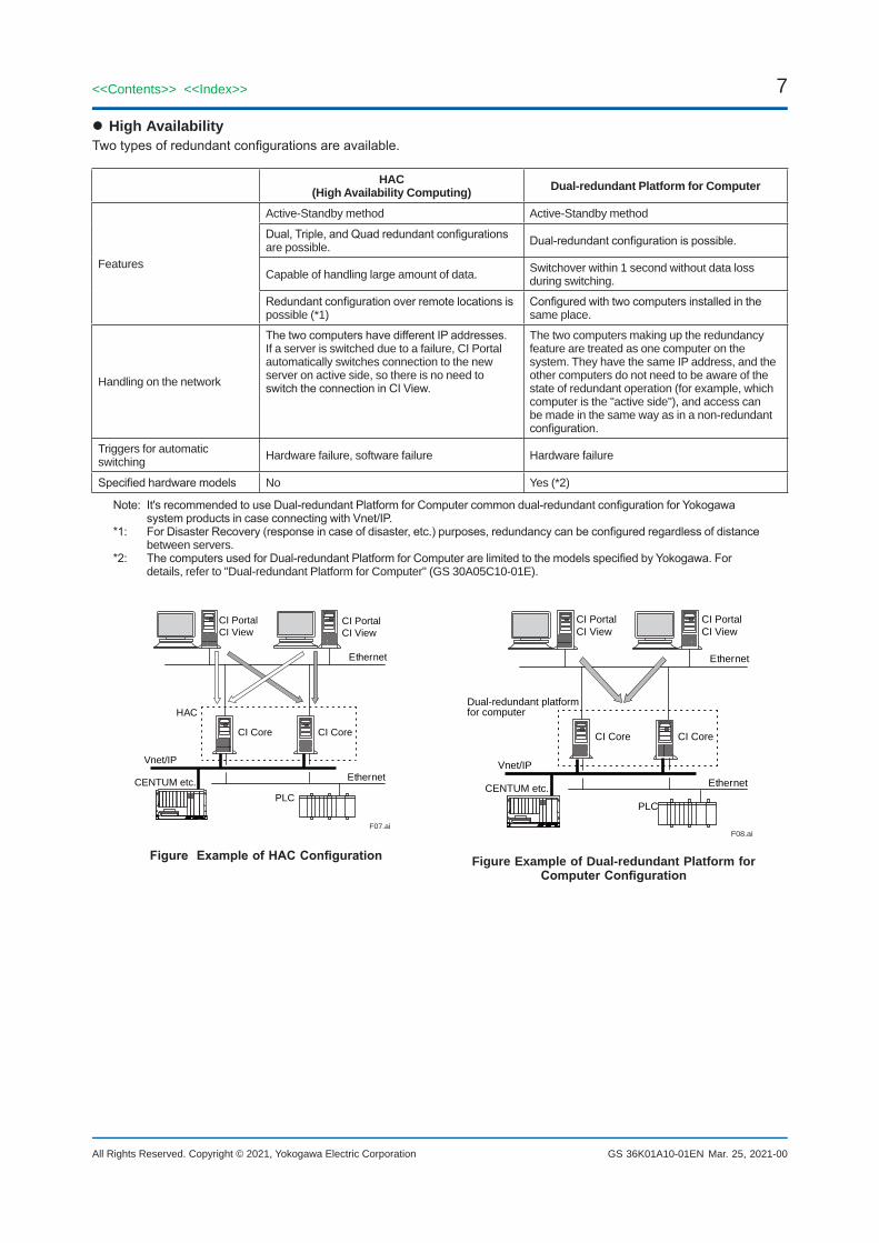
High AvailabilityTwotypesofredundantconfigurationsareavailable.
HAC(High Availability Computing) Dual-redundant Platform for Computer
Features
Active-Standby method Active-Standby method
Dual,Triple,andQuadredundantconfigurationsare possible. Dual-redundantconfigurationispossible.
Capable of handling large amount of data. Switchover within 1 second without data loss during switching.
Redundantconfigurationoverremotelocationsispossible (*1)
Configuredwithtwocomputersinstalledinthesame place.
Handling on the network
ThetwocomputershavedifferentIPaddresses.If a server is switched due to a failure, CI Portal automatically switches connection to the new server on active side, so there is no need to switchtheconnectioninCIView.
The two computers making up the redundancy feature are treated as one computer on the system. They have the same IP address, and the other computers do not need to be aware of the state of redundant operation (for example, which computer is the "active side"), and access can be made in the same way as in a non-redundant configuration.
Triggers for automatic switching Hardware failure, software failure Hardware failure
Specifiedhardwaremodels No Yes (*2)
Note:It'srecommendedtouseDual-redundantPlatformforComputercommondual-redundantconfigurationforYokogawasystemproductsincaseconnectingwithVnet/IP.
*1: ForDisasterRecovery(responseincaseofdisaster,etc.)purposes,redundancycanbeconfiguredregardlessofdistancebetween servers.
*2: ThecomputersusedforDual-redundantPlatformforComputerarelimitedtothemodelsspecifiedbyYokogawa.Fordetails, refer to "Dual-redundant Platform for Computer" (GS 30A05C10-01E).
Mar. 25, 2021-00
CI PortalCI View
CI PortalCI View
F07.ai
HAC
Ethernet
CI Core CI Core
Vnet/IP
CENTUM etc. Ethernet
PLC
FigureExampleofHACConfiguration
Dual-redundant platformfor computer
F08.ai
Ethernet
CI PortalCI View
CI PortalCI View
CI Core CI Core
Vnet/IP
CENTUM etc. Ethernet
PLC
Figure Example of Dual-redundant Platform for ComputerConfiguration

8
All Rights Reserved. Copyright © 2021, Yokogawa Electric Corporation
<<Contents>> <<Index>>
GS 36K01A10-01EN
nEXTERNAL INTERFACECI Server supports industry standards such as OPC UA and ODBC. CI Server supports native communication drivers to Yokogawa products as well as various controllers of 3rd parties.
Linkage with External Applications
Interface Option Code Description
OPC Classic client (*1) (*3) OPC DA v2.04OPC A&E v1.02
OPC Classic server (*1) /PCD OPC DA v2.04OPC A&E v1.02
OPC Classic Tunneller (*1) /PCT
OPC DA TunnellerThis function is needed to the computer installed 3rd-parties' OPC Classic Server/Client to communicate with CI Server via secure communication used among CI Cores.
OPC UA client (*2) (*3) OPC UA DA v1.04Supports redundant communication with OPC UA server
OPC UA server (*2)/PCU
OPC UA DA v1.04OPC UA A&C v1.04 OPC UA HA v1.04
OPC UA PubSub (*2) OPC UA v1.04
ODBC server (*1) /PDBForbothprocessandconfigurationdata,ODBCAPIconformancelevel1,SQLconformance level minimum.Only 32-bit is supported
MQTT (*1) (*3) MQTT 3.1.1Communication with lower and higher targets (IIOT devices) by MQTT protocol.
Relational database (RDB) connection (*1) (*3)
Supported RDB: MS SQL Server 2016 SP2 or later.Data can be sent and received to/from applications that use RDB through the RDB. CI Core connects to the RDB and synchronizes data between CI Core and the RDB. When data in CI Core is changed, the data is copied to the RDB.WhenthedataintheRDBischanged,itwillbereflectedinthedataonCIServer.
*1: Supported on Windows OS only.*2: Supported on Windows OS and Linux OS.*3: Supported as standard function and does not need to select any Option Codes when ordering.
Mar. 25, 2021-00

9<<Contents>> <<Index>>
All Rights Reserved. Copyright © 2021, Yokogawa Electric Corporation GS 36K01A10-01EN
External Controller Connection
Interface Option Code Description
YokogawaVnet/IP(*1)
(*3)
CENTUMVPR5.01.20orlaterProSafe-RS R2.02 or later
Yokogawa STARDOM (*1) R2.01 or later
Yokogawa DAQSTATION (*1) Please contact Yokogawa for details.
Yokogawa DAQMASTER (*1) Please contact Yokogawa for details.
Yokogawa SMARTDAC+ (*1) Please contact Yokogawa for details.
Yokogawa FA-M3 (*1) Please contact Yokogawa for details.
Modbus slave
Modbus master
IEC 60870-5 driver (*1) /DEC IEC 60870-5-101/102/103/104
IEC 61850 driver /DEP SupportsMMSspecificationsandcanreadandwritefrom/totags.Includes SISCO stock layer software.
DNP3 master /DDN
WITS level 0 slave function (*1) /DWS WellsiteInformationTransferSpecification(WITS)
WITS level 0 Master function (*1) /DWM WellsiteInformationTransferSpecification(WITS)
HEX repeater /DHE
Rockwell Automation communication driver /DRC Rockwell CIP, Rockwell DF1, Rockwell DH+
Siemens communication driver (*1) /DSE Siemens 3964R, Siemens SAPI-S7(SIMATIC.NET SAPI-7 software package is required.)
Emerson communication driver /DEM
MELSEC communication driver (*1) (*2) /DME
OMRON communication driver /DMR OMRON FINS driver
Telemetry integration environment /DTE Telemetry Integration Environment (TIE)
HART router /DHA
Allen Bradley CIP driver /DAC
Allen Bradley PLC5 driver /DAP
BeckhoffADSdriver /DBA
BeckhoffBK8100driver /DBK
Bachmann M1COM driver /DBM
Bristol Babcock driver /DBB
Fisher ROC driver /DFR
Note: Please contact Yokogawa for connectable versions.*1: Supported on Windows OS only.*2: Supported on Windows client OS only.*3: Supported as standard function and does not need to select any Option Codes when ordering.
Mar. 25, 2021-00

10
All Rights Reserved. Copyright © 2021, Yokogawa Electric Corporation
<<Contents>> <<Index>>
GS 36K01A10-01EN
nSECURITYSecurity-related functions include IT security function, encrypted communication, user management, and audit trailing. In addition, Yokogawa's Endpoint Security Service can be applied.
IT Security FunctionThis function uses the security function of Windows OS to fortify the CI Server components. IT Security Tool is providedtoconfigurethisfeature.ThistooliscommonlyinstalledinYokogawasystemproductsandenablesconfigurationofsecuritysettings.Thefollowingthreatsareaddressed:
Threat Description
Attack over the network Threatsfromunauthorizedpersonsthroughnetworks,whichaffectthesystemorstealimportant data.
Direct attack by terminal operation Threatsfromunauthorizedpersonswhooperateterminals,whichaffectthesystemorstealimportant data.
Computer/data theft Threats where computers with important data are stolen.
Theapplicablesecuritymeasuresareclassifiedintothefollowingtypes.
Measure DescriptionAccess control Restrictsaccesstofiles,folders,registries,andprograms.
Personalfirewalltuning Controls communications among computers on the network.
Stopping unused Windows services Stops programs and services that are not in use.
Changing IT environment settings Enables strong Windows security measures.
Applying group policy settings Enables centralized management of security policies for computers connected to the same domain.
Encrypted CommunicationThe following encrypted communications are supported:• Encryption of communications among CI Servers CommunicationbetweenCIPortalandCIView:SecureSocketsLayer(SSL)isused. Communication between CI Cores and communication between CI Core and CI Portal: Secure UDP
communications and public/private keys are used.• Encryption of OPC UA communication By using the encryption function of OPC UA, secure and reliable communication is available.
User ManagementThe following authorizations can be set by users:• Operating and displaying windows• Operating devices and data• Generating reports and trends•Alarmmanagement,notification,andacknowledgment• Operation log (automatic or manual)• Scope of engineering
The following user authentications are available:• Authentication by CI Server (Authentication by Windows can be used together)• Integration with Windows user authentication process and account settings Single sign-on (SSO) can be used by integrating with Active Directory. Using the Simple and Protected GSS-
API Negotiation mechanism (SPNEGO), which is a standard method for user authentication of web servers, web authentication by SSO is supported for HTTP requests.
Jan. 29, 2021-00

11<<Contents>> <<Index>>
All Rights Reserved. Copyright © 2021, Yokogawa Electric Corporation GS 36K01A10-01EN
Audit TrailLogon/logout history and operation records for data are saved as an audit trail. Audit trail data can be displayed on the screenandoutputasreports.Also,theoperationsanddatatosaveasanaudittrailcanbedefined.
Items saved are as follows:• Events
-Login, logout, login failure-Insert, change, delete data (by operator or application)-Alarm acknowledgment (by operator or application)-Alarm shelving and un-shelving operations
• Event occurrence time stamp• Name of the user who operated• Name of the computer on which the operation was performed• Valuesbeforeandafterthechange(Forexample,whenchangingdata,thevaluesbeforeandafterthechangewill
be saved.)• Event related items
-Data name-Program name-Alarmnotificationdestination-Users to notify of alarms-Userprofile-Controller interface
• Name of the program that generated the event• Information for each application (if any application is created in the project)
Endpoint Security ServiceYokogawa's Endpoint Security Service is provided to reduce the risk of malware infection on Windows PCs and servers and helps maintain system health throughout the life cycle.
Anti-virus SoftwareThe anti-virus software is dedicated for Yokogawa control systems based on the McAfee’s intrusion prevention technologies. This product is used as standard anti-virus software for Yokogawa IA systems.
Whitelisting SoftwareThe whitelisting software is the security measure software using the McAfee's application control technologies and with whitelist method provided with the optimum settings for Yokogawa control systems. This product is used at malware measure service for Yokogawa IA systems.
For more details, please refer to the GS 43D02T30-02E "Endpoint Security Service".
nHMI FUNCTION Features• Operability
CI Server enables users to freely create operation and monitoring windows based on ergonomics and the guidelines stipulatedbycompaniesorinprojects,andsupportsefficientoperationandmonitoring.Screenoperationssuchaszooming and scrolling are also provided as standard functions.
• HTML5 supportOperation and monitoring windows support HTML5 format for displaying on Web browser and mobile devices
• Flexible Graphic DeploymentTheoperationandmonitoringwindowsarefreelyconfiguredbycombiningthestandardpartssuchasprocessdata,alarms, historical trends, real-time trends, faceplates, reports, and event history, and parts created for each project. Multiple layers and visibility groups can be set for each window, and they can be shown or hidden according to user authorizations, process conditions, and the zoom level.
• HMIwithhighvisualeffectThebuilt-inISA-101compliantsymbollibraryenableseasycreationofHMIwithhighvisualeffects.AdvancedOperating Graphics (AOG), a consulting service provided by Yokogawa, is supported.
• VariousdatasourcesDashboard screens can be easily displayed because of the ability to display information from a variety of data sources such as video streaming (such as camcorders) and websites.
• Multi-node inputData collected from multiple CI Cores can be integrated and displayed on a single operation and monitoring window. For example, it is possible to collect from each CI Core only the data requested in a certain management level and display them.
Jan. 29, 2021-00

12
All Rights Reserved. Copyright © 2021, Yokogawa Electric Corporation
<<Contents>> <<Index>>
GS 36K01A10-01EN
Trend GraphReal-time data and historical data are displayed seamlessly. The user interface is easy to operate and allows for efficienttrendconfiguration.Penassignmentstothetrendgraphs,displayitems,anddisplayformatmaybeconfiguredbothattheengineeringstageandduringoperationandmonitoring.Fromthetrendscreen,itispossibletosavetheconfigurationdataformultiple trends and call up the trends.
Key features:• Maximum number of pens: 50 per one trend component• Minimum displayable time unit: 1 ms• Minimum update cycle: 1 second• Maximum display time span: No limit• Number of storable trends: Depends on disk capacity Save, call up, print, and protect trends•Exporttrenddataandimages(bitmap,CSVfile)• Setting accessible users• High-speed historical trend• 2D/3D/tabular rendering• Line segment graph/steps graph/scatter chart/area chart• XY plots• Show/hide legend and scale• Reversing of time and value axis• Scale fonts• Trend display in absolute time/relative time and shift time span• Display alarm status on the hairline• Linked display of trend and alarm overview• Pen assignment by drag-and-drop• Range-scale and time-scale zoom function (XY-axis simultaneous zooming with rectangular selection is also
possible)• Show/hide value slider, time slider, time control, 3D control, hairline, and pen panel•MicroTrend(smallsizesimplifiedtrendavailableforISA-101-compliantscreens)•DTSTrend(trenddisplayof3DdataacquiredfromYokogawaDTSXopticalfibertemperaturesensordevices,thatis,temperature,distance,timedatacollectedateachpointalongtheopticalfibercable)
Jan. 29, 2021-00

13<<Contents>> <<Index>>
All Rights Reserved. Copyright © 2021, Yokogawa Electric Corporation GS 36K01A10-01EN
nHISTORICAL Historical DataAll data handled in CI Server can be saved as historical data. The types of data are as follows:• Data (data collected from the systems and controllers, internal calculation data)• Alarm• Audit Trail• System log
Historical data can be output to the following:• Screen display• Trend• Report•Textfile
Thefollowingtimingcanbespecifiedtosavehistoricaldata:• Save periodically• Save on event (when the value changes, etc.)
AggregationsThe aggregation calculation function is provided for creating daily reports, monthly reports, etc.• Aggregation cycle 30 minutes, hourly, shift-based, daily, weekly, monthly, and yearly aggregation• Aggregation function Minimum,maximum,mean,integral,standarddeviation,counter,anddifferentialsummation
ReportHistoricaldataandconfigurationinformationcanbeoutputastabularortime-seriesreports.
Item DescriptionFormat FreelyconfigurableOutput destination Selectablefromgraphicdisplay,file,andprinterbyreport
Generation timing
Automaticallycreatedatthespecifiedtime,fixedcycle,oreventoccurrence.On-demand manual creation is also possible
Excel Add-in ReportReports can also be created by using Excel Add-in. Making it easy to create reports such as daily and monthly reports and analyze process data because data in CI Core can be acquired via a work book. Since the range of accessible data can be limited by each user, secure data retrieval is ensured.
Jan. 29, 2021-00

14
All Rights Reserved. Copyright © 2021, Yokogawa Electric Corporation
<<Contents>> <<Index>>
GS 36K01A10-01EN
nALARM AlarmingAlarms which have been generating are listed on a current alarm overview screen that can operation such as alarm confirmation.Alarmscanbenotifiedbye-mailandSMS.Historyofalarmsarelistedonahistoricalalarmoverviewscreen.CI Server generates and displays alarms on its own. Alarms generated outside the CI Server (e.g. CENTUM system) can be captured and displayed via OPC A&E. Alarms are saved as historical data (alarm history). The saved alarm history can be displayed in the historical alarm overview and the report function. Alarms can only be viewed and manipulated by authorized users.The alarming functionality consists of the following functions.
Category Function Description
Alarm detectionJudgment by limit Judges the presence of an alarm condition based on the high/low limit values
of the item value.OPC AE alarm detection Captures alarm information from an OPC AE server.
Alarm acknowledgment Alarm acknowledgment Operators perform the operation to acknowledge important alarms.
Alarm display/operation
Alarm overview Lists active alarms or alarms that were active in the past.
Alarm sound Plays the alarm sound according to the alarm that has occurred.
Area of Interest Filters the alarms by the label attached to the data.
Alarm selection area Filters alarms by conditional expression.
Alarm shelving Temporarily shelves low-priority alarms to respond to high-priority alarms.
Alarm link display From the alarm overview, calls up the window related to the active alarm.
Exporttofile Exportsalarmstoafile.
Alarm inhibition Alarmscanbeturnedoffforeachdataordevice.
Alarm groupFirst-out group Showsonlythefirstalarminthegroup.Multiplegroupscanbenested.
Alarm collection group Manages alarm states collectively for grouped alarm sources.
Alarmnotification Alarmnotification SendsalarmnotificationbyemailorSMS.
Report Report function Outputs alarms as reports.
The alarming functionality consists of the following functions.
Name Description
Current alarm overview Displays active alarms. Alarm acknowledgement operation is performed on this screen.
Historical alarm overviewDisplays the records/history of alarms that occurred and returned to normal in the past, and acknowledgement operation and other alarm operations performed.
Shelved alarm overview Displays alarms that have been shelved and moved from the current alarm overview.
Filterscanbeusedforalarmdisplay/operationandalarmnotification.Twotypesoffiltersareavailable:
Type DescriptionFilter by date and time Filters by specifying the date and time or specifying the period.
Filter by conditions Filters by data name, area of interest, or alarm selection area.
The following display behavior can be set for alarms.
Type Description
Delayed alarm Displays as an alarm only when the alarm state continues for a certain period of time.
Repeated alarm Displaysasanalarmatspecifiedtimeintervalsifthespecifiedtimeelapseswhile the alarm state remains.
May. 19, 2021-00

15<<Contents>> <<Index>>
All Rights Reserved. Copyright © 2021, Yokogawa Electric Corporation GS 36K01A10-01EN
With the alarm grouping function, the situation where many individual alarms are raised can be avoided to reduce the load of the operator responding to alarms. There are two types of groups:
Type Description
First-out groupThisisamechanismtoavoidthatthealarmoverviewbecomesafloodofalarmsbydisplayingonlythefirstraisedalarminthegroup,suppressingthealarms in the group that would otherwise be raised after that. Multiple groups can be nested.
Alarm collection group Active/acknowledged/reset states are managed collectively for grouped alarm sources.
Alarm System Performance Analysis (ASPA)ASPA is a function that analyzes alarm data history and creates reports. ASPA provides performance analysis accordingtoEEMUA191andISA18.2,whichareguidelinesforensuringthequalityandeffectivenessofalarmsystems, and displays the analysis results in graphs and charts. By taking measures according to the analysis results, the load on the operator and the risk of critical alarms being overlooked can be reduced to avoid making mistakes or delays in making decisions to ensure safety.
Main analysis items:• Operator load KPI (EEMUA191 section 4.1.1)• Operator load performance (EEMUA191 section 4.1.2)•Alarmrateandalarmflood(EEMUA191appendixA12.7)• Top ten alarm factors (EEMUA191 appendix A12.6)• Long-standing alarm (EEMUA191 appendix A12.8)• Correlation of serious alarms (EEMUA191 appendix A12.11)
n APPLICATION Linkage with GISThis function links to a Geographic Information System (GIS) and acquires map images from an external Web mapping server to display various information of CI Server on the map by superimposing the symbol graphics of CI Server.
DTSX FunctionDistributedTemperatureSensor(DTSX)isasensorthatusesafiber-opticcabletomeasuretemperaturesalongthelength of the cable. CI Server can acquire data from the Yokogawa DTSX module and display it on the trend screen.
AGA CalculationsThe AGA (American Gas Association standards) calculation function consists of a set of functions.The AGA calculation function covers the following standards:•AGA3:Orificemeteringofnaturalgasandotherrelatedhydrocarbongases• AGA7: Measurement of natural gas by turbine meters• AGA8: Compressibility factors of natural gas and other related hydrocarbon gases• AGA9: Measurement of gas by multipath ultrasonic meters• AGA10: Speed of sound in natural gas and other related hydrocarbon gases• AGA11: Measurement of natural gas by Coriolis meter•V-Cone:MeasurementofnaturalgasbyV-cone• Water-Cone: Measurement of natural gas by Water-cone
Further, the following additional calculations are supported:• Gross heating value, relative density and compressibility factor for natural gas mixtures from composition analysis
by AGA5 or GPA2172 method• Atmospheric pressure depending on latitude and altitude
Mar. 25, 2021-00

16
All Rights Reserved. Copyright © 2021, Yokogawa Electric Corporation
<<Contents>> <<Index>>
GS 36K01A10-01EN
n ENGINEERING FUNCTION FeaturesCI Server provides engineering environment for re-using engineering data, operation and monitoring windows, and graphic components of operation and monitoring windows. Engineering in a remote environment and engineering usingtextfilesarealsopossible.Engineeringcanbeperformedefficientlyevenforlargescalesystem.Allitemsinthefollowing "ListofEngineeringItems"canbedefinedwhiletheCIServerisrunning.
List of Engineering Items•UserdefinitionDefinetheuserswhoperformoperationandmonitoringandtheuserandtheauthorityfortheonewhoperformsengineering.Defineuser'sauthoritytoanauthoritygroupandassignausertotheauthorithgroup.
•ControllerconnectiondefinitionSet controllers to be connected and communication protocols for the connection.
•ExternalinterfacedefinitionWhenusingexternalinterfaces,defineeachexternalinterface.
•OperationandmonitoringdatadefinitionDefinethehierarchicalstructures,names,andattributesofthedatathatCIServerwillhandle.The below is examples of attributes.
-Data type, engineering unit-Mapping with data in the controller-Alarm settings for each data (limit value, display color, group, acknowledgement type, etc.)
•DataprocessingdefinitionCI Server can start a program created in advance according to the timing of events (changes in collected data, etc.) oradefinedschedule.Twoprogramminglanguagesareavailable:JavaandlanguagespecifictoCIServer.Variouscalculations and process control operations that use multiple data can be programmed.
•AlarmdefinitionDefinetheitemsdescribedin" Alarming" above.
•DefinitionforhistoricaldatamanagementDefinethedatasavedashistoricaldata,andthesettings(fixedcycle/eventbaseandsavingperiod).Definethesettings to a historical group and assing the saving data to the historical group.
•AudittraildefinitionDefineifthereareitemsthatneedtobesavedasanaudittrailinadditiontothedefaultsaveitems.
•ReportdefinitionDefinetheformat,outputtiming,andoutputdestinationofreports.
•OperationandmonitoringwindowdefinitionCreate windows for operation and monitoring.Maindefinitionitems:
- Placement of components (graphics, text, data display, bar graphs, etc.)- Placement of symbols (graphics of equipment such as pumps and tanks, ISA symbols, etc.)- Placement of HMI components (alarm overview, trends, reports, etc.)- Attribute settings (display/setting data, window expansion, color change, animation, etc.) of each placed
componentThetoolforcreatingwindowshasvariousmechanismsforefficientwindowcreation.In the tool, graphics commonly used for equipment and devices are registered as reusable symbols. Symbols can be created and registered.
- Window parts called components are provided.- Template windows can be created.- The windows and parts (symbols, components, etc.) on the window are easily copied.
Jan. 29, 2021-00

17<<Contents>> <<Index>>
All Rights Reserved. Copyright © 2021, Yokogawa Electric Corporation GS 36K01A10-01EN
List of Engineering ToolsEngineering tool Definableitems
Engineering Module
UserdefinitionController connectionOperationandmonitoringdatadefinitionDataprocessingdefinitionAlarm settingsDefinitionforhistoricaldatamanagementAudittraildefinitionReportdefinition
Edit Module Operationandmonitoringwindowdefinition
Setup File Editor Basicconfigurationofthesystem
Quick Load Tool Allitems(Configurationimport/exporttool)
CENTUM VP ConnectionAtoolthatextractsnecessaryinformationfromtheCENTUMVPprojectdatabaseandconvertsittoaCIServerdatabaseisprovided.Withthistool,CIServerandCENTUMVPcanbeconnectedeasily.SupporteddatabasesareofCENTUMVP,ProSafe-RS,STARDOM,andCCCProdigy.
nAPPLICATION CAPACITYTable CI Server application capacity
Item Specification Remarks
Maximum number of CI Cores (*1) 4095 stationsIn the case of HAC, the number of CI Cores actually installed is counted. If more than 4095 CI Cores are needed, please consult Yokogawa.
Maximum number of controllers that can be connected to one CI Core 10000 stations
Maximum number of CI Core hierarchy layers 128 levelsMaximum number of CI Portals that can be connected to one CI Core (*1) 4095 stations
MaximumnumberofCIViewsthatcanbeconnectedtoone CI Portal 500 stations IncludestheCIViewsthatrunonthesamecomputerasCI
Portal and HTML5 clients.Maximum number of monitors that can be connected to oneCIView 4 stations
Maximumnumberofdataitemsthatcanbedefined 16 million data
Maximum length of data name 256 characters Includes the dots (.) delimiting the levels in the name.
Maximum number of levels in data hierarchies 128 levels
Maximum length of a data hierarchy level name 31 characters
Number of HMI screens Unlimited
Minimum update cycle of HMI screen display 1 secondDependingonthesystemconfigurationandthenumberofdatadefinedononewindow,updatein100millisecondsispossible. Please contact Yokogawa for details.
Maximum number of users Unlimited
Maximum number of user groups Unlimited
*1: The total number of nodes (= computer stations) in one domain may not exceed 4095 (computer stations with only a Cl ViewinstalledarenotcountedasaNode).
Jan. 29, 2021-00

18
All Rights Reserved. Copyright © 2021, Yokogawa Electric Corporation
<<Contents>> <<Index>>
GS 36K01A10-01EN
nOPERATING ENVIRONMENT Software Operating EnvironmentOS
Platform Name
Microsoft Windows
Windows 10 Pro (64-bit)
Windows 10 Enterprise (64-bit)
Windows 10 Enterprise 2016 LTSB
Windows 10 IoT Enterprise 2016 LTSB
Windows 10 Enterprise 2019 LTSC
Windows 10 IoT Enterprise 2019 LTSC
Windows Server 2016
Windows Server 2019
LinuxRed Hat Enterprise Linux 8.1 (64-bit)
CentOS 8.1 (64-bit)
Note: For software of other companies that runs on Windows or Linux, there are limitations on the combination with the CI Server software and usage, so please contact Yokogawa.
Note: Please contact YOKOGAWA for using CI Server with Linux.IT Security Tool
IT Security Tool Supported OS
IT security version 2.0
Windows 10 Enterprise 2016 LTSB
Windows 10 IoT Enterprise 2016 LTSB
Windows 10 Enterprise 2019 LTSC
Windows 10 IoT Enterprise 2019 LTSC
Windows Server 2016
Dual-redundant Platform for Computer
Dual-redundant Platform for Computer Windows Server 2016
Note: Formoredetails,pleaserefertotheGS30A05C10-01EN“Dual-redundantPlatformforComputer”.Web browser
Web browser
Google Chrome 84 or later
Mozilla Firefox 78 or later
Microsoft Edge 84 or later
Web browser (for CI View HTML5 client)
Webbrowser(forCIViewHTML5client) Google Chrome 84 or later
Microsoft Excel (for Excel Add-in reports)
CI Server Microsoft ExcelSuppot OS
Version Version Edition
R1.01
Office2019(32-bit / 64-bit)
StandardProfessional Plus
Windows 10 LTSC 2019 (64-bit)Windows 10 Enterprise (64-bit)Windows 10 Pro (64-bit)
Office2016(32-bit / 64-bit)
Windows Server 2016 (64-bit)Windows 10 LTSB 2016 (64-bit)Windows 10 Enterprise (64-bit)Windows 10 Pro (64-bit)
PDF reader (for viewing Instruction Manuals)
PDF reader (for viewing Instruction Manuals) Adobe Acrobat Reader DC
Feb. 27, 2021-00

19<<Contents>> <<Index>>
All Rights Reserved. Copyright © 2021, Yokogawa Electric Corporation GS 36K01A10-01EN
Hardware Operating EnvironmentCI CoreHardware requirements for CI Core are shown below. CICorerunsoncomputerswiththefollowingspecifications.
Table CI Core hardware operating environment
CPU Mandatory Intel Core i7 3.40 GHz or higher
Main memory Mandatory 8 GB or more (*1)
Hard disk Mandatory Hard disk with a capacity of 1 TB or more
Communication device
Mandatory(IncaseVnet/IPconnection)
VI702(controlbusinterfacecard)PCI Express
Mandatory (In case Ethernet connection) Ethernet compatible network port (*2)
DVD drive Mandatory AdrivesupportedbytheOSused.AnexternalDVD-ROMdrivecan also be used.
*1: When using ASPA, 16 GB or more is required.*2: Pleasepreparethenumberofthisaccordingtothenetworkconfiguration.WhenusingHAC,usingadedicatednetwork
port for HAC is recommended.
CI PortalHardware requirements for CI Portal are shown below. CIPortalrunsoncomputerswiththefollowingspecifications.
Table CI Portal hardware operating environment)
CPU Mandatory Intel Core i7 3.40GHz or higher
Main memory Mandatory 8 GB or more (*1)
Hard disk Mandatory Hard disk with a capacity of 1TB or more
Communication device Mandatory Ethernet compatible network port (*2)
DVD drive Mandatory AdrivesupportedbytheOSused.AnexternalDVD-ROMdrivecan also be used.
Peripherals Mandatory Sound function (*3)
*1: When using ASPA, 16 GB or more is required.*2: Pleasepreparethenumberofthisaccordingtothenetworkconfiguration.*3: Required only when using audio output such as alarm sound.
CI ViewHardwarerequirementsforCIViewareshownbelow. CIViewrunsoncomputerswiththefollowingspecifications(IBMPC/ATcompatibles).
TableCIViewhardwareoperatingenvironment(whenCICoreandCIPortalrunondifferentcomputers)
CPU Mandatory Intel Core i7 3.40GHz or higher
Main memory Mandatory 8 GB or more
Hard disk Mandatory Hard disk with a capacity of 500 GB or more and free space of 1 GB or more
Communication device Mandatory Ethernet compatible network card 1 Gb (*1)
DVD drive Mandatory AdrivesupportedbytheOSused.AnexternalDVD-ROMdrivecan also be used.
Peripherals Mandatory Sound card (*2)
Note: The hardware also that doesn't meet performance described in the above can be used as CI view if its performance meets a purpose of a project according to the screen contents; in case the CI view is not used as a main component of operation and monitoring or is used with a tablet device.
*1: ThenumberofportsincludingonboardEthernet.Prepareasmanyasneededaccordingtothenetworkconfiguration.*2: Required only when using audio output such as alarm sound.
Jan. 29, 2021-00

20
All Rights Reserved. Copyright © 2021, Yokogawa Electric Corporation
<<Contents>> <<Index>>
GS 36K01A10-01EN
nMODEL AND SUFFIX CODES CI Server Software Medium
DescriptionModel CS2CKM CI Server Software Medium
SuffixCodes
-D Suppliedmedium:DVD
1 Always 1
1 Always 1
CI Server User Manual Medium
DescriptionModel CS2CKM2 CI Server User Manual Medium
SuffixCodes
-C Supplied medium: CD-R
1 Always 1
1 Always 1
CI Server Software LicenseLicenseconfiguration
DescriptionModel CS2CLC CI Server software license
SuffixCodes
-L Software license 1 Always 1 1 Always 1
OptionCodes
YOKOGAWA Controller
Connection(*1)
/FCS FCS Connection
/UGS UGS/UGS2 Connection
/SCS SCS Connection
/FNS FCN Connection
CI Core for Windows
(*2)
/CA CI Core Max Item Numbers: 1,000 (*3)
/CB CI Core Max Item Numbers: 2,000 (*3)
/CC CI Core Max Item Numbers: 4,000 (*3)
/CD CI Core Max Item Numbers: 8,000 (*3)
/CE CI Core Max Item Numbers: 16,000 (*3)
/CF CI Core Max Item Numbers: 32,000 (*3)
/CG CI Core Max Item Numbers: 64,000 (*3)
/CH CI Core Max Item Numbers: 128,000 (*3)
/CJ CI Core Max Item Numbers: 256,000 (*3)
/CK CI Core Max Item Numbers: Unlimited (*3)
Feb. 27, 2021-00

21<<Contents>> <<Index>>
All Rights Reserved. Copyright © 2021, Yokogawa Electric Corporation GS 36K01A10-01EN
Description
OptionCodes
CI Core for LINUX
/LA CICore(LINUX)Max Item Numbers: 1,000 (*3)
/LB CICore(LINUX)Max Item Numbers: 2,000 (*3)
/LC CICore(LINUX)Max Item Numbers: 4,000 (*3)
/LD CICore(LINUX)Max Item Numbers: 8,000 (*3)
/LE CICore(LINUX)Max Item Numbers: 16,000 (*3)
/LF CICore(LINUX)Max Item Numbers: 32,000 (*3)
/LG CICore(LINUX)Max Item Numbers: 64,000 (*3)
/LH CICore(LINUX)Max Item Numbers: 128,000 (*3)
/LJ CICore(LINUX)Max Item Numbers: 256,000 (*3)
/LK CICore(LINUX)Max Item Numbers: Unlimited (*3)
CI Core Extension
/CAB Ex Items Numbers: 1,000 to 2,000
/CBC Ex Items Numbers: 2,000 to 4,000
/CCD Ex Items Numbers: 4,000 to 8,000
/CDE Ex Items Numbers: 8,000 to 16,000
/CEF Ex Items Numbers: 16,000 to 32,000
/CFG Ex Items Numbers: 32,000 to 64,000
/CGH Ex Items Numbers: 64,000 to 128,000
/CHJ Ex Items Numbers: 128,000 to 256,000
/CJK Ex Items Numbers: 256,000 to UnlimitedCI Portal /PTL Additional CI Portal (*4)
CI View/VER AdditionalCIView(OperatorInterface)
/VEM AdditionalCIView(HTML5)
Equipment Driver
/DEC IEC 60870-5 Protocol
/DEP IEC 61850 Protocol
/DDN DNP3 Master Driver
/DWS WITS Level 0 Slave
/DWM WITS Level 0 Master
/DHE HEX Repeater
/DRC Rockwell Automation Driver
/DSE Siemens Driver
/DEM Emerson Driver
/DME MELSEC Driver
/DMR OMRON FINS Driver
/DTE Telemetry Integration Environment (TIE)
/DHA HART Router
/DAC Allen Bradley CIP
/DAP Allen Bradley PLC5
/DBK BeckhoffBK8100
/DBA BeckhoffADS
/DBM Bachmann M1COM
/DBB Bristol Babcock
/DFR Fisher ROC
Mar. 25, 2021-00

22
All Rights Reserved. Copyright © 2021, Yokogawa Electric Corporation
<<Contents>> <<Index>>
GS 36K01A10-01EN
Description
OptionCodes
Interface
/PCU OPC UA Server (DA/A&C/HA)
/PCD OPC Classic Server (DA/A&E)
/PCT OPC Tunneller
/PDB ODBC Server
Redundant Architecture
/A1H Double HAC (*5)
/A2H Triple HAC (*5)
/A3H Quad HAC (*5)
/ADR Dual Redundant Platform for Computer (*6)Architecture /EES CI Core for Enterprise Engineering Sever
Application
/ASP ASPA
/DTS DTSX
/GYS GIS
/PTR PI Trend
Note: Please refer to the "■ EXTERNAL INTERFACE" described earlier for the limitation of OS each of Option Codes.Note Specify the required number of licenses in the last two digits () of each option code.Note: An item is an area in the CI Server for storing one piece of data. The data from a controller or data created in CI Server by
calculation is stored.*1: Please prepare according to the number of Yokogawa controllers.*2: This option is required to use the CI Core function. OneofeachofcomponentsCICore,CIPortal,andCIViewincluded.*3: Purchase a license with as many as the items excluding the items of Yokogawa controllers to be connected. To connect
Yokogawa controllers, separately purchase the item options /FCS,/UGS,/SCS,/FNS for the number of controllers.*4: OneCIPortalandoneCIViewareincluded.*5: Licenses for the number of CI Cores that will actually be installed for the redundancy are required. For example, when
selectingdualHAC"/A1H01",specifythatthenumberineachoptioncodeisdoubled.ForaspecificexampleofMScodeselection,refertothesection"Standaloneconfigurationwithclientsadded"below.
*6: “Dual-redundantPlatformforComputer”(PC2CKM)mustbeorderedseparately.Noneedtoorder“Dual-redundantPlatformVersatileLicense”(FT2SDR01).
Examples of License SelectionThe MS code of CI Server license is consisted as combination the part of CI Core function and the part of the other necessary optional function.AnexampleofMScodeusedforthesystemconsistedwithCICore,CIPortal,andCIViewisinbelow.Please make sure to place an order for a product maintenance license “CIServerSoftwareMaintenance”afterCIServer software license purchased.
IncaseofStandaloneConfiguration
F09.ai
Ethernet
Ethernet
Vnet/IP
CENTUM etc. PLC
CI CoreCI PortalCI View
Node Option Codes Item Description
CI coreYOKOGAWA Controller Connection /FCS 1 FCS Connection
CI Core for Windows /CE 1 CI Core Max Item Numbers: 16,000
Note: Modbus communication interface is included as standard in case CI server communicates with PLC via Modbus.
Please specify the following MS Code;CS2CLC-L11/FCS01/CE01
Mar. 25, 2021-00

23<<Contents>> <<Index>>
All Rights Reserved. Copyright © 2021, Yokogawa Electric Corporation GS 36K01A10-01EN
IncaseofRemoteCIPortal/RemoteCIViewConfiguration
F10.ai
CI ViewCI View
CI Core CI Core
CI Portal 2CI View
CI Portal 1CI View
Ethernet
Ethernet
Vnet/IP
CENTUM etc. PLC
Example 1: Dual-redundant Platform for ComputerExample 2: HAC
CI view(HTML5)
CI view(HTML5)
Example 1: Dual-redundant Platform for ComputerPleasespecify/ADRandalsoplaceanorderfora“Dual-redundantPlatformforComputer”(PC2CKM)touseDual-redundant Platform for Computer.
Node Option Codes Item DescriptionCI Core YOKOGAWA Controller Connection /FCS 5 FCS Connection
CI Core for Windows /CG 1 CI Core Max Item Numbers: 64,000
Equipment Driver /DDN 1 DNP3 Master Driver
Redundant Architecture /ADR 1 Dual Redundant Platform for Computer
CI Portal 1 CI Portal /PTL 1 Additional CI Portal
CIView /VER 1 AdditionalCIView(OperatorInterface)
CIView /VEM 1 AdditionalCIView(HTML5)
CI Portal 2 CI Portal /PTL 1 Additional CI Portal
CIView /VER 1 AdditionalCIView(OperatorInterface)
CIView /VEM 1 AdditionalCIView(HTML5)
Please specify the following MS Code;CS2CLC-L11/FCS05/CG01/DDN01/ADR01/PTL02/VER02/VEM02
Mar. 25, 2021-00

24
All Rights Reserved. Copyright © 2021, Yokogawa Electric Corporation
<<Contents>> <<Index>>
GS 36K01A10-01EN
Example 2: HACthe same number of the licenses with the number of computers used as dual-redundant are needed for HAC configuration.IncaseHACconfigurationwithdual-redundant,pleasespecifyeachofOptioncodesaccordingtotheTwo of computers.
Node Option Codes Item DescriptionCI Core YOKOGAWA Controller Connection /FCS 10 FCS Connection
CI Core for Windows /CG 2 CI Core Max Item Numbers: 64,000
Equipment Driver /DDN 2 DNP3 Master Driver
Redundant Architecture /A1H 1 Double HAC
CI Portal 1 CI Portal /PTL 1 Additional CI Portal
CIView /VER 1 AdditionalCIView(OperatorInterface)
CIView /VEM 1 AdditionalCIView(HTML5)
CI Portal 2 CI Portal /PTL 1 Additional CI Portal
CIView /VER 1 AdditionalCIView(OperatorInterface)
CIView /VEM 1 AdditionalCIView(HTML5)
Please specify the following MS Code;CS2CLC-L11/FCS10/CG02/DDN02/A1H01/PTL02/VER02/VEM02
IncaseofGatewayConfiguration
F11.ai
Ethernet
Ethernet
Vnet/IP
CENTUM etc. PLC
CI Core
3rd-party system
This is an example for using OPC-UA to connect with 3rd-party products.
Node Option Codes Item DescriptionCI Core YOKOGAWA Controller Connection /FCS 1 FCS Connection
CI Core for Windows /CK 1 CI Core Max Item Numbers: Unlimited
Interface /PCU 1 OPC UA Server (DA/A&C/HA)
Please specify the following MS Code;CS2CLC-L11/FCS01/CK01/PCU01
nORDERING INFORMATIONSpecifythemodelandsuffixcode(s).
Mar. 25, 2021-00

25<<Contents>> <<Index>>
All Rights Reserved. Copyright © 2021, Yokogawa Electric Corporation GS 36K01A10-01EN
25<<Contents>> <<Index>>
Subject to change without notice.
n SOFTWARE LICENSE AGREEMENT AND LIMITED WARRANTY Software License AgreementBefore using the CI Server release 1 software products, refer to the website below and agree on all the terms and conditionsof“CIServerRelease1SoftwareLicenseAgreement.”
CI Server Release 1 Software License Agreement:http://www.yokogawa.com/EndUserLicenseAgreement/
Limited WarrantyCI Server is provided with the limited warranty which covers its software media only. Support services over vulnerability and non-conformance shall be provided by Product Maintenance License (PML) and Lifecycle Agreement. For more details of PML for CI Server, please refer to the GS 30A01F30-01EN "Product Maintenance License".
n TRADEMARK ACKNOWLEDGMENTThe names of corporations, organizations, products and logos herein are either registered trademarks or trademarks of Yokogawa Electric Corporation and their respective holders.
Mar. 25, 2021-00